EP3800422B1 - Plate for a heat exchanger device - Google Patents
Plate for a heat exchanger device Download PDFInfo
- Publication number
- EP3800422B1 EP3800422B1 EP20195433.6A EP20195433A EP3800422B1 EP 3800422 B1 EP3800422 B1 EP 3800422B1 EP 20195433 A EP20195433 A EP 20195433A EP 3800422 B1 EP3800422 B1 EP 3800422B1
- Authority
- EP
- European Patent Office
- Prior art keywords
- plate
- heat exchanger
- sector
- ridge
- ridges
- Prior art date
- Legal status (The legal status is an assumption and is not a legal conclusion. Google has not performed a legal analysis and makes no representation as to the accuracy of the status listed.)
- Active
Links
- 230000007704 transition Effects 0.000 claims description 38
- 239000012530 fluid Substances 0.000 description 16
- 238000009826 distribution Methods 0.000 description 12
- XEEYBQQBJWHFJM-UHFFFAOYSA-N Iron Chemical compound [Fe] XEEYBQQBJWHFJM-UHFFFAOYSA-N 0.000 description 8
- PXHVJJICTQNCMI-UHFFFAOYSA-N Nickel Chemical compound [Ni] PXHVJJICTQNCMI-UHFFFAOYSA-N 0.000 description 8
- 239000007788 liquid Substances 0.000 description 8
- RYGMFSIKBFXOCR-UHFFFAOYSA-N Copper Chemical compound [Cu] RYGMFSIKBFXOCR-UHFFFAOYSA-N 0.000 description 5
- RTAQQCXQSZGOHL-UHFFFAOYSA-N Titanium Chemical compound [Ti] RTAQQCXQSZGOHL-UHFFFAOYSA-N 0.000 description 5
- 239000010949 copper Substances 0.000 description 5
- 229910052802 copper Inorganic materials 0.000 description 5
- 238000001704 evaporation Methods 0.000 description 5
- 239000010936 titanium Substances 0.000 description 5
- 229910052719 titanium Inorganic materials 0.000 description 5
- QGZKDVFQNNGYKY-UHFFFAOYSA-N Ammonia Chemical compound N QGZKDVFQNNGYKY-UHFFFAOYSA-N 0.000 description 4
- XAGFODPZIPBFFR-UHFFFAOYSA-N aluminium Chemical compound [Al] XAGFODPZIPBFFR-UHFFFAOYSA-N 0.000 description 4
- 229910052782 aluminium Inorganic materials 0.000 description 4
- 239000010941 cobalt Substances 0.000 description 4
- 229910017052 cobalt Inorganic materials 0.000 description 4
- GUTLYIVDDKVIGB-UHFFFAOYSA-N cobalt atom Chemical compound [Co] GUTLYIVDDKVIGB-UHFFFAOYSA-N 0.000 description 4
- 229910052742 iron Inorganic materials 0.000 description 4
- 229910052759 nickel Inorganic materials 0.000 description 4
- 238000005219 brazing Methods 0.000 description 3
- 239000000470 constituent Substances 0.000 description 3
- 230000013011 mating Effects 0.000 description 3
- 239000007769 metal material Substances 0.000 description 3
- 238000011144 upstream manufacturing Methods 0.000 description 3
- 238000004026 adhesive bonding Methods 0.000 description 2
- 229910021529 ammonia Inorganic materials 0.000 description 2
- 230000004927 fusion Effects 0.000 description 2
- 239000000463 material Substances 0.000 description 2
- 238000003825 pressing Methods 0.000 description 2
- 238000003466 welding Methods 0.000 description 2
- 229910000975 Carbon steel Inorganic materials 0.000 description 1
- 229910045601 alloy Inorganic materials 0.000 description 1
- 239000000956 alloy Substances 0.000 description 1
- 230000004888 barrier function Effects 0.000 description 1
- 239000010962 carbon steel Substances 0.000 description 1
- 230000000295 complement effect Effects 0.000 description 1
- 239000002826 coolant Substances 0.000 description 1
- 230000007797 corrosion Effects 0.000 description 1
- 238000005260 corrosion Methods 0.000 description 1
- 230000008020 evaporation Effects 0.000 description 1
- 230000003993 interaction Effects 0.000 description 1
- 238000005304 joining Methods 0.000 description 1
- 238000004519 manufacturing process Methods 0.000 description 1
- 238000000034 method Methods 0.000 description 1
- 238000012986 modification Methods 0.000 description 1
- 230000004048 modification Effects 0.000 description 1
- 238000000926 separation method Methods 0.000 description 1
- 239000010935 stainless steel Substances 0.000 description 1
- 229910001220 stainless steel Inorganic materials 0.000 description 1
- XLYOFNOQVPJJNP-UHFFFAOYSA-N water Substances O XLYOFNOQVPJJNP-UHFFFAOYSA-N 0.000 description 1
Images


Classifications
-
- F—MECHANICAL ENGINEERING; LIGHTING; HEATING; WEAPONS; BLASTING
- F28—HEAT EXCHANGE IN GENERAL
- F28D—HEAT-EXCHANGE APPARATUS, NOT PROVIDED FOR IN ANOTHER SUBCLASS, IN WHICH THE HEAT-EXCHANGE MEDIA DO NOT COME INTO DIRECT CONTACT
- F28D9/00—Heat-exchange apparatus having stationary plate-like or laminated conduit assemblies for both heat-exchange media, the media being in contact with different sides of a conduit wall
- F28D9/0006—Heat-exchange apparatus having stationary plate-like or laminated conduit assemblies for both heat-exchange media, the media being in contact with different sides of a conduit wall the plate-like or laminated conduits being enclosed within a pressure vessel
-
- F—MECHANICAL ENGINEERING; LIGHTING; HEATING; WEAPONS; BLASTING
- F28—HEAT EXCHANGE IN GENERAL
- F28F—DETAILS OF HEAT-EXCHANGE AND HEAT-TRANSFER APPARATUS, OF GENERAL APPLICATION
- F28F3/00—Plate-like or laminated elements; Assemblies of plate-like or laminated elements
- F28F3/02—Elements or assemblies thereof with means for increasing heat-transfer area, e.g. with fins, with recesses, with corrugations
- F28F3/04—Elements or assemblies thereof with means for increasing heat-transfer area, e.g. with fins, with recesses, with corrugations the means being integral with the element
-
- F—MECHANICAL ENGINEERING; LIGHTING; HEATING; WEAPONS; BLASTING
- F28—HEAT EXCHANGE IN GENERAL
- F28D—HEAT-EXCHANGE APPARATUS, NOT PROVIDED FOR IN ANOTHER SUBCLASS, IN WHICH THE HEAT-EXCHANGE MEDIA DO NOT COME INTO DIRECT CONTACT
- F28D21/00—Heat-exchange apparatus not covered by any of the groups F28D1/00 - F28D20/00
- F28D21/0001—Recuperative heat exchangers
- F28D21/0014—Recuperative heat exchangers the heat being recuperated from waste air or from vapors
-
- F—MECHANICAL ENGINEERING; LIGHTING; HEATING; WEAPONS; BLASTING
- F28—HEAT EXCHANGE IN GENERAL
- F28D—HEAT-EXCHANGE APPARATUS, NOT PROVIDED FOR IN ANOTHER SUBCLASS, IN WHICH THE HEAT-EXCHANGE MEDIA DO NOT COME INTO DIRECT CONTACT
- F28D9/00—Heat-exchange apparatus having stationary plate-like or laminated conduit assemblies for both heat-exchange media, the media being in contact with different sides of a conduit wall
- F28D9/0031—Heat-exchange apparatus having stationary plate-like or laminated conduit assemblies for both heat-exchange media, the media being in contact with different sides of a conduit wall the conduits for one heat-exchange medium being formed by paired plates touching each other
- F28D9/0037—Heat-exchange apparatus having stationary plate-like or laminated conduit assemblies for both heat-exchange media, the media being in contact with different sides of a conduit wall the conduits for one heat-exchange medium being formed by paired plates touching each other the conduits for the other heat-exchange medium also being formed by paired plates touching each other
-
- F—MECHANICAL ENGINEERING; LIGHTING; HEATING; WEAPONS; BLASTING
- F28—HEAT EXCHANGE IN GENERAL
- F28D—HEAT-EXCHANGE APPARATUS, NOT PROVIDED FOR IN ANOTHER SUBCLASS, IN WHICH THE HEAT-EXCHANGE MEDIA DO NOT COME INTO DIRECT CONTACT
- F28D9/00—Heat-exchange apparatus having stationary plate-like or laminated conduit assemblies for both heat-exchange media, the media being in contact with different sides of a conduit wall
- F28D9/0031—Heat-exchange apparatus having stationary plate-like or laminated conduit assemblies for both heat-exchange media, the media being in contact with different sides of a conduit wall the conduits for one heat-exchange medium being formed by paired plates touching each other
- F28D9/0043—Heat-exchange apparatus having stationary plate-like or laminated conduit assemblies for both heat-exchange media, the media being in contact with different sides of a conduit wall the conduits for one heat-exchange medium being formed by paired plates touching each other the plates having openings therein for circulation of at least one heat-exchange medium from one conduit to another
-
- F—MECHANICAL ENGINEERING; LIGHTING; HEATING; WEAPONS; BLASTING
- F28—HEAT EXCHANGE IN GENERAL
- F28F—DETAILS OF HEAT-EXCHANGE AND HEAT-TRANSFER APPARATUS, OF GENERAL APPLICATION
- F28F3/00—Plate-like or laminated elements; Assemblies of plate-like or laminated elements
- F28F3/02—Elements or assemblies thereof with means for increasing heat-transfer area, e.g. with fins, with recesses, with corrugations
- F28F3/04—Elements or assemblies thereof with means for increasing heat-transfer area, e.g. with fins, with recesses, with corrugations the means being integral with the element
- F28F3/042—Elements or assemblies thereof with means for increasing heat-transfer area, e.g. with fins, with recesses, with corrugations the means being integral with the element in the form of local deformations of the element
- F28F3/046—Elements or assemblies thereof with means for increasing heat-transfer area, e.g. with fins, with recesses, with corrugations the means being integral with the element in the form of local deformations of the element the deformations being linear, e.g. corrugations
-
- F—MECHANICAL ENGINEERING; LIGHTING; HEATING; WEAPONS; BLASTING
- F28—HEAT EXCHANGE IN GENERAL
- F28D—HEAT-EXCHANGE APPARATUS, NOT PROVIDED FOR IN ANOTHER SUBCLASS, IN WHICH THE HEAT-EXCHANGE MEDIA DO NOT COME INTO DIRECT CONTACT
- F28D21/00—Heat-exchange apparatus not covered by any of the groups F28D1/00 - F28D20/00
- F28D2021/0019—Other heat exchangers for particular applications; Heat exchange systems not otherwise provided for
- F28D2021/0061—Other heat exchangers for particular applications; Heat exchange systems not otherwise provided for for phase-change applications
- F28D2021/0064—Vaporizers, e.g. evaporators
-
- F—MECHANICAL ENGINEERING; LIGHTING; HEATING; WEAPONS; BLASTING
- F28—HEAT EXCHANGE IN GENERAL
- F28D—HEAT-EXCHANGE APPARATUS, NOT PROVIDED FOR IN ANOTHER SUBCLASS, IN WHICH THE HEAT-EXCHANGE MEDIA DO NOT COME INTO DIRECT CONTACT
- F28D21/00—Heat-exchange apparatus not covered by any of the groups F28D1/00 - F28D20/00
- F28D21/0017—Flooded core heat exchangers
-
- F—MECHANICAL ENGINEERING; LIGHTING; HEATING; WEAPONS; BLASTING
- F28—HEAT EXCHANGE IN GENERAL
- F28F—DETAILS OF HEAT-EXCHANGE AND HEAT-TRANSFER APPARATUS, OF GENERAL APPLICATION
- F28F2250/00—Arrangements for modifying the flow of the heat exchange media, e.g. flow guiding means; Particular flow patterns
- F28F2250/10—Particular pattern of flow of the heat exchange media
- F28F2250/102—Particular pattern of flow of the heat exchange media with change of flow direction
Definitions
- the invention relates to a plate for a heat exchanger device.
- Heat exchanger devices are well known for evaporating various types of cooling medium such as ammonia, freons, etc., in applications for generating e.g. cold.
- the evaporated medium is conveyed from the heat exchanger device to a compressor and the compressed gaseous medium is thereafter condensed in a condenser. Thereafter the medium is permitted to expand and is recirculated to the heat exchanger device.
- One example of such heat exchanger device is a heat exchanger of the plate-and-shell type.
- a heat exchanger of the plate-and-shell type is known from WO2004/111564 which discloses a plate package composed of substantially half-circular heat exchanger plates.
- the use of half-circular heat exchanger plates is advantageous since it provides a large volume inside the shell in the area above the plate package, which volume improves separation of liquid and gas.
- the separated liquid is transferred from the upper part of the inner space to a collection space in the lower part of the inner space via an interspace.
- the interspace is formed between the inner wall of the shell and the outer wall of the plate package.
- the interspace is part of a thermo-syphon loop which sucks the liquid towards the collection space of the shell.
- EP 2 394 129 discloses a heat exchanger having a plurality of heat exchanger plates comprising ridges and valleys. Each of the ridges and valleys has a V-shaped configuration and a connection part including a projection forming a joining area.
- the heat exchanger should have an efficient heat transfer and it should typically be compact and of robust design. Moreover, the respective plates should be easy and cost-effective to manufacture.
- a first transition ridge may be formed, in either the plates of the first or the second type, as a stem branching off into two legs.
- Such a design is useful when the angle between the ridges is comparably small such as smaller than 40°, and the design is especially useful when the angle is smaller than 30°, or even smaller than 25°.
- the stem may abut a plurality, preferably at least three, consecutive chevron shaped ridge transitions of the other one of the first or second type of plates, the ridge transitions being formed between the two adjacent flow path sectors having ridges extending at an angle relative to each other. This allows for a strong abutment between the plates even when the angle between the ridges of respective flow path sector is small.
- At least one of the two legs and/or the stem may along its longitudinal extension have a portion with a locally enlarged width as seen in a direction transverse the longitudinal extension. This may be used to minimise any deviation from the ridge pattern of respective flow path sector.
- the first leg may extend in parallel with the ridges of its adjacent sector and the second leg may extend in parallel with the ridges of its adjacent sector. This way any deviation from the ridge pattern of respective flow path sector is minimised.
- a second transition ridge may be formed as a stem which preferably branches off into two legs, wherein the stem of the second transition ridge is arranged between the two legs of the first transition ridge.
- the first and second transition ridges are oriented in the same direction. It may be said that the first and second transition ridges in a sense look like arrows pointing in the same direction.
- the second transition ridge may be designed according to the design specified in relation to the first transition ridge above.
- a plate for a heat exchanger device such as a plate heat exchanger
- the plate comprising a first sector with mutually parallel ridges and an adjoining second sector with mutually parallel ridges extending at an angle relative to the ridges of the first sector, the plate further comprising at least one transition ridge formed as a stem branching off into two legs.
- the angle between the ridges i.e. between the ridges of the first sector and the ridges of the adjoining second sector, may be smaller than 40°, such as smaller than 30°, such as smaller than 25°.
- the stem has a length exceeding twice, preferable thrice, a distance from ridge to ridge of the mutually parallel ridges of the first sector and of the second sector. This may be used to secure that the stem abuts a plurality, preferably at least three, consecutive chevron shaped ridge transitions of the other one of the first or second type of plates, the ridge transitions being formed between the two adjacent flow path sectors having ridges extending at an angle relative to each other. This allows for a strong abutment between the plates even when the angle between the ridges of respective flow path sector is small.
- At least one of the two legs and/or the stem may along its longitudinal extension have a portion with a locally enlarged width as seen in a direction transverse the longitudinal extension. This may be used to minimise any deviation from the ridge pattern of respective flow path sector.
- the first leg may extend in parallel with the ridges of its adjacent sector and the second leg may extend in parallel with the ridges of its adjacent sector.
- a second transition ridge may be formed as a stem which preferably branches off into two legs, wherein the stem of the second transition ridge is arranged between the two legs of the first transition ridge.
- a heat exchanger device including a shell which forms a substantially closed inner space
- the heat exchanger device comprises a plate package including a plurality of heat exchanger plates of a first type and a plurality of heat exchanger plates of a second type arranged alternatingly in the plate package one on top of the other, wherein each heat exchanger plate has a geometrical main extension plane and is provided in such a way that the main extension plane is substantially vertical when installed in the heat exchanger device, wherein the alternatingly arranged heat exchanger plates form first plate interspaces, which are substantially open and arranged to permit a flow of a medium to be evaporated there-through, and second plate interspaces, which are closed and arranged to permit a flow of a fluid for evaporating the medium,
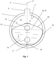
- the heat exchanger device includes a shell 1, which forms a substantially closed inner space 2.
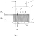
- the shell 1 has a substantially cylindrical shape with a substantially cylindrical shell wall 3, see Fig. 1 , and two substantially plane end walls (as shown in Fig.2 ).
- the end walls may also have a semi- spherical shape, for instance. Also other shapes of the shell 1 are possible.
- the shell 1 comprises a cylindrical inner wall surface 3 facing the inner space 2.
- a sectional plane p extends through the shell 1 and the inner space 2.
- the shell 1 is arranged to be provided in such a way that the sectional plane p is substantially vertical.
- the shell 1 may by way of example be of carbon steel.
- the shell 1 includes an inlet 5 for the supply of a two-phase medium in a liquid state to the inner space 2, and an outlet 6 for the discharge of the medium in a gaseous state from the inner space 2.
- the inlet 5 includes an inlet conduit which ends in a lower part space 2' of the inner space 2.
- the outlet 6 includes an outlet conduit, which extends from an upper part space 2" of the inner space 2.
- the medium may by way of example be ammonia.
- the heat exchanger device includes a plate package 10, which is provided in the inner space 2 and includes a plurality of heat exchanger plates 11a, 11b provided adjacent to each other.
- the heat exchanger plates 11a, 11b are discussed in more detail in the following with reference in Fig. 3 .
- the heat exchanger plates 11 are permanently connected to each other in the plate package 10, for instance through welding, brazing such as copper brazing, fusion bonding, or gluing. Welding, brazing and gluing are well-known techniques and fusion bonding can be performed as described in WO 2013/144251 A1 .
- the heat exchanger plates may be made of a metallic material, such as a iron, nickel, titanium, aluminum, copper or cobalt based material, i.e.
- a metallic material e.g. alloy
- Iron, nickel, titanium, aluminum, copper or cobalt may be the main constituent and thus be the constituent with the greatest percentage by weight.
- the metallic material may have a content of iron, nickel, titanium, aluminum, copper or cobalt of at least 30% by weight, such as at least 50% by weight, such as at least 70% by weight.
- the heat exchanger plates 11 are preferably manufactured in a corrosion resistant material, for instance stainless steel or titanium.
- Each heat exchanger plate 11a, 11b has a main extension plane q and is provided in such a way in the plate package 10 and in the shell 1 that the extension plane q is substantially vertical and substantially perpendicular to the sectional plane p.
- the sectional plane p also extends transversally through each heat exchanger plate 11a, 11b. In the embodiment is disclosed, the sectional plane p also thus forms a vertical centre plane through each individual heat exchanger plate 11a, 11b.
- Plane q may also be explained as being a plane parallel to the plane of the paper onto which e.g. Fig. 4 is drawn.
- the heat exchanger plates 11a, 11b form in the plate package 10 first interspaces 12, which are open towards inner space 2, and second plate interspaces 13, which are closed towards the inner space 2.
- the medium mentioned above, which is supplied to the shell 1 via the inlet 5, thus pass into the plate package 10 and into the first plate interspaces 12.
- Each heat exchanger plate 11a, 11b includes a first port opening 14 and a second port opening 15.
- the first port openings 14 form an inlet channel connected to an inlet conduit 16.
- the second port openings 15 form an outlet channel connected to an outlet conduit 17. It may be noted that in an alternative configuration, the first port openings 14 form an outlet channel and the second port openings 15 form an inlet channel.
- the sectional plane p extends through both the first port opening 14 and the second port opening 15.
- the heat exchanger plates 11 are connected to each other around the port openings 14 and 15 in such a way that the inlet channel and the outlet channel are closed in relation to the first plate interspaces 12 but open in relation to the second plate interspaces 13. A fluid may thus be supplied to the second plate interspaces 13 via the inlet conduit 16 and the associated inlet channel formed by the first port openings 14, and discharged from the second plate interspaces 13 via the outlet channel formed by the second port openings 14 and the outlet conduit 17.
- the plate package 10 has an upper side and a lower side, and two opposite transverse sides.
- the plate package 10 is provided in the inner space 2 in such a way that it substantially is located in the lower part space 2' and that a collection space 18 is formed beneath the plate package 10 between the lower side of the plate package and the bottom portion of the inner wall surface 3.
- recirculation channels 19 are formed at each side of the plate package 10. These may be formed by gaps between the inner wall surface 3 and the respective transverse side or as internal reciruclation channels formed within the plate package 10.
- Each heat exchanger plate 11 includes a circumferential edge portion 20 which extends around substantially the whole heat exchanger plate 11 and which permits said permanent connection of the heat exchanger plates 11 to each other. These circumferential edge portions 20 will along the transverse sides abut the inner cylindrical wall surface 3 of the shell 1.
- the recirculation channels 19 are formed by internal or external gaps extending along the transverse sides between each pair of heat exchanger plates 11. It is also to be noted that the heat exchanger plates 11 are connected to each other in such a way that the first plate interspaces 12 are closed along the transverse sides, i.e. towards the recirculation channels 19 of the inner space 2.
- the example of the heat exchanger device disclosed in this application may be used for evaporating a two-phase medium supplied in a liquid state via the inlet 5 and discharged in a gaseous state via the outlet 6.
- the heat necessary for the evaporation is supplied by the plate package 10, which via the inlet conduit 16 is fed with a fluid for instance water that is circulated through the second plate interspaces 13 and discharged via the outlet conduit 17.
- the medium, which is evaporated, is thus at least partly present in a liquid state in the inner space 2.
- the liquid level may extend to the level 22 indicated in Fig. 1 . Consequently, substantially the whole lower part space 2' is filled by medium in a liquid state, whereas the upper part space 2" contains the medium in mainly the gaseous state.
- the heat exchanger plates 11a may be of the kind disclosed in Fig. 3 .
- the heat exchanger plates 11b may also be of the kind disclosed in Fig. 3 but 180° about the line pq forming the intersection beteen the sectional plane p and the main extension plane q.
- the second heat exchanger plate 11b may be similar to the heat exchanger plate 11a but with all or some of the upright standing flanges 24 removed.
- around the port openings 14, 15 there is provided a distribution pattern surronding each port opening 14, 15 on the second interspace side 13. However, since such patterns are well-known in the art and since it does not form part of the invention, it is for clarity reasons omitted in the drawings.
- the plate package 10 includes a plurality of heat exchanger plates 11a of a first type and a plurality of heat exchanger plates 11b of a second type arranged alternatingly in the plate package 10 one on top of the other (as e.g. shown in fig. 2 ).
- Each heat exchanger plate 11a, 11b has a geometrical main extension plane q and is provided in such a way that the main extension plane q is substantially vertical when installed in the heat exchanger device (as shown in fig. 1 and fig. 2 ).
- first plate interspaces 12 which are substantially open and arranged to permit a flow of a medium to be evaporated there-through
- second plate interspaces 13 which are closed and arranged to permit a flow of a fluid for evaporating the medium.
- Each of the heat exchanger plates 11a, 11b of the first type and of the second type has a first port opening 14 at a lower portion of the plate package 10 and a second port opening 15 at an upper portion of the plate package 10, the first and second port openings 14, 15 being in fluid connection with the second plate interspaces 13.
- the heat exchanger plates 11a, 11b of the first type and of the second type further comprise mating abutment portions 30 forming a fluid distribution element 31 in the respective second plate interspaces 13.
- the mating abutment portions 30 may e.g. be formed as a ridge 30 extending upwardly in the plate 11a shown in Fig. 3 which interacts with a corresponding ridge of the abutting plate 11b formed by turning the plate 11a 180° about the line pq, thereby giving the abutment shown in Fig. 7 .
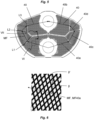
- the fluid distribution element 31 has a longitudinal extension L31 having mainly a horizontal extension along a horizontal plane H and being located as seen in a vertical direction V in a position between the first port openings 14 and the second port openings 15, thereby forming in the respective second plate interspaces 13 two arc-shaped flow paths 40 extending from the first port opening 14, around the fluid distribution element 31, and to the second port opening 15, or vice versa.
- Respective one of the two flow paths 40 is divided into at least three flow path sectors 40a, 40b, 40c, 40d arranged one after the other along respective flow path 40.
- Each of the heat exchanger plates 11a, 11b of the first type and of the second type in each flow path sector 40a-d comprises a plurality of mutually parallel ridges 50a-d, 50a'-d'.
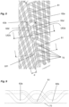
- the ridges 50a-d, 50a'-d' of the heat exchanger plates 11a, 11b of the first and second types are oriented (see Fig. 4 ) such that when they abut each other (as shown in Fig. 5 and the enlargement in Fig. 6 ) they form a chevron pattern relative to a main flow direction MF in the respective flow path sector 40a-d, wherein respective ridge form an angle ⁇ being greater than 45° to the main flow direction MF in respective flow path sector 40a-d.
- the main flow directions MF of respective flow path sector is indicated by the four arrows in each flow path as shown in Fig. 5 .
- the ridges 50a in the first sector 40a on the right hand side of the plate is oriented differently than the ridges 50a' in the first sector 40a' on the left hand side.
- the ridges 50a' will abut the ridges 50a and thereby form the above mentioned chevron pattern.
- respective ridge forms an angle ⁇ being greater than 45° relative to the main flow direction in respective flow path sector
- abutting ridges together form a chevron angle ⁇ ' being greater than 90 °, the chevron angle being measured from ridge of one plate to ridge of the other plate inside the chevron shape.
- the angle ⁇ is preferably greater than 50° and is more preferably greater than 55°.
- the chevron angle ⁇ ' is preferably greater than 100° and is more preferably greater than 110°.
- Fig. 5 is at least a first 40a of the flow path sectors 40a-d arranged in the lower portion of the plate package 10, at least a second 40b of the path sectors 40a-d is arranged in the upper portion of the plate package 10, and at least a third 40c and preferably also a fourth 40d of the flow path sectors 40a-d is arranged in a transition between the upper and lower portions.
- the fluid distribution element 31 comprises a mainly horizontally extending central portion 31a-b and two wing portions 31c, 31d extending upwardly and outwardly from either end of the central portion 31a-b.
- the distribution element 31 basically acts as a barrier in the second plate interspaces 13.
- the fluid distribution element 31 may be provided with small openings e.g. in the corners between the central portion 31a, 31b and the wing portions 31c, 31d. Such openings may e.g. be used as drainage openings.
- the fluid distribution element 31 is mirror symmetrical about a vertical plane p extending transversely to the main extension planes q and through centres of the first and second port openings 14, 15.
- Respective demarcation line L1, L2, L3 between adjoining sectors 40ad extends from the fluid distribution element 31 outwardly, preferably rectilinearly, towards an outer edge of the respective heat exchanger plate 11a-b. It may be noted that the demarcation lines L1, L2, L3 extends completely through the flow path area 40a-d. The white area outside the chevron pattern may be used to provide internal recirculation channels 19
- the main flow direction MF in the first sector 40a extends from the inlet port 14 to a central portion of a demarcation line L1 between the first sector 40a and the adjoining downstream sector 40c.
- Respective main flow direction MF in a sector extends from a central portion of respective demarcation line L1 between the sector 40c and an adjoining upstream sector 40a to a central portion of respective demarcation line L2 between the sector 40c and an adjoining downstream sector 40d.
- the main flow direction MF in the second sector 40b extends from a central portion of the demarcation line L3 between the second sector 40b and an adjoining upstream sector 40d to the outlet port 15.
- the central portion of respective demarcation line L1, L2, L3 comprises a mid-point of respective demarcation line and up to 15%, preferably up to 10%, of the length of the respective demarcation line on either side of the mid-point.
- the respective main flow direction MF in a sector extends substantially from a mid-point of respective demarcation line between the sector and an adjoining upstream sector substantially to a mid-point of respective demarcation line between the sector and an adjoining downstream sector.
- the flow may be in the opposite direction when the port 15 forms and inlet port and port 14 forms an outlet port.
- a first transition ridge 60 is formed, in either the plates of the first or the second type, as a stem 61 branching off into two legs 62a-b.
- the stem 61 abuts a plurality, preferably at least three, and in Fig. 8 four, consecutive chevron shaped ridge transitions 70 of the other one of the first or second type of plates, the ridge transitions 70 being formed between the two adjacent flow path sectors having ridges extending at an angle relative to each other.
- Fig. 8 it is shown that the two legs 62a, 62b along its longitudinal extension L62a, L62b has a portion 62a', 62b' with a locally enlarged width as seen in a direction transverse the longitudinal extension L62a, L62b.
- the first leg 62a extends in parallel with the ridges of its adjacent sector and the second leg 62b extends in parallel with the ridges of its adjacent sector.
- a second transition ridge 80 may be formed as a stem branching off into two legs, wherein the stem of the second transition ridge 80 is arranged between the two legs of the first transition ridge. In the figure, the second transition ridge is only a stem 81.
- the locally enlarged width may for instance be formed on the stem 61 instead or as a complement to the locally enlarged width of the legs 62a, 62b.
Landscapes
- Engineering & Computer Science (AREA)
- Physics & Mathematics (AREA)
- Thermal Sciences (AREA)
- Mechanical Engineering (AREA)
- General Engineering & Computer Science (AREA)
- Heat-Exchange Devices With Radiators And Conduit Assemblies (AREA)
Priority Applications (5)
| Application Number | Priority Date | Filing Date | Title |
|---|---|---|---|
| PL20195433.6T PL3800422T3 (pl) | 2017-03-10 | 2017-03-10 | Płyta do urządzenia wymiennika ciepła |
| EP20195433.6A EP3800422B1 (en) | 2017-03-10 | 2017-03-10 | Plate for a heat exchanger device |
| DK20195433.6T DK3800422T3 (da) | 2017-03-10 | 2017-03-10 | Plade til en varmeveksleranordning |
| ES20195433T ES2966217T3 (es) | 2017-03-10 | 2017-03-10 | Placa para un dispositivo intercambiador de calor |
| SI201731433T SI3800422T1 (sl) | 2017-03-10 | 2017-03-10 | Plošča za napravo za izmenjevanje toplote |
Applications Claiming Priority (2)
| Application Number | Priority Date | Filing Date | Title |
|---|---|---|---|
| EP17160262.6A EP3372941B1 (en) | 2017-03-10 | 2017-03-10 | Plate package, plate and heat exchanger device |
| EP20195433.6A EP3800422B1 (en) | 2017-03-10 | 2017-03-10 | Plate for a heat exchanger device |
Related Parent Applications (2)
| Application Number | Title | Priority Date | Filing Date |
|---|---|---|---|
| EP17160262.6A Division-Into EP3372941B1 (en) | 2017-03-10 | 2017-03-10 | Plate package, plate and heat exchanger device |
| EP17160262.6A Division EP3372941B1 (en) | 2017-03-10 | 2017-03-10 | Plate package, plate and heat exchanger device |
Publications (2)
| Publication Number | Publication Date |
|---|---|
| EP3800422A1 EP3800422A1 (en) | 2021-04-07 |
| EP3800422B1 true EP3800422B1 (en) | 2023-10-25 |
Family
ID=58266477
Family Applications (2)
| Application Number | Title | Priority Date | Filing Date |
|---|---|---|---|
| EP17160262.6A Active EP3372941B1 (en) | 2017-03-10 | 2017-03-10 | Plate package, plate and heat exchanger device |
| EP20195433.6A Active EP3800422B1 (en) | 2017-03-10 | 2017-03-10 | Plate for a heat exchanger device |
Family Applications Before (1)
| Application Number | Title | Priority Date | Filing Date |
|---|---|---|---|
| EP17160262.6A Active EP3372941B1 (en) | 2017-03-10 | 2017-03-10 | Plate package, plate and heat exchanger device |
Country Status (12)
| Country | Link |
|---|---|
| US (2) | US11162736B2 (da) |
| EP (2) | EP3372941B1 (da) |
| JP (1) | JP6968187B2 (da) |
| KR (1) | KR102232401B1 (da) |
| CN (2) | CN114279242B (da) |
| CA (2) | CA3119508C (da) |
| DK (2) | DK3800422T3 (da) |
| ES (2) | ES2839409T3 (da) |
| PL (1) | PL3800422T3 (da) |
| SI (2) | SI3800422T1 (da) |
| TW (1) | TWI676779B (da) |
| WO (1) | WO2018162199A1 (da) |
Families Citing this family (6)
| Publication number | Priority date | Publication date | Assignee | Title |
|---|---|---|---|---|
| FR3050519B1 (fr) * | 2016-04-25 | 2019-09-06 | Novares France | Echangeur thermique en matiere plastique et vehicule comprenant cet echangeur thermique |
| US11035626B2 (en) * | 2018-09-10 | 2021-06-15 | Hamilton Sunstrand Corporation | Heat exchanger with enhanced end sheet heat transfer |
| JP6783836B2 (ja) * | 2018-09-19 | 2020-11-11 | 株式会社前川製作所 | プレート重合体及び熱交換器 |
| DK3660437T3 (da) * | 2018-11-29 | 2021-10-18 | Alfa Laval Corp Ab | Pladevarmeveksler og varmevekslerplade til behandling af en tilførsel, såsom havvand |
| JP6860095B1 (ja) * | 2020-01-14 | 2021-04-14 | ダイキン工業株式会社 | シェルアンドプレート式熱交換器 |
| JP2021110516A (ja) * | 2020-01-14 | 2021-08-02 | ダイキン工業株式会社 | シェルアンドプレート式熱交換器 |
Family Cites Families (60)
| Publication number | Priority date | Publication date | Assignee | Title |
|---|---|---|---|---|
| SE105870C1 (da) | ||||
| GB391894A (en) | 1931-11-27 | 1933-05-11 | Albert Percival Snelling | Improvements in or relating to plate heat-exchange apparatus for fluids particularlyapplicable to the cooling of milk |
| GB444073A (en) | 1934-09-12 | 1936-03-12 | Stone J & Co Ltd | Improvements in plate heat exchange apparatus for fluids |
| DE641600C (de) | 1935-06-30 | 1937-02-06 | Eduard Ahlborn Akt Ges | Waermeaustauschplatte mit auf die Platte aufvulkanisierten Gummifuehrungsteilen, die durch mit der Platte verbundene drahtartige Teile gesichert sind |
| GB581742A (en) | 1943-04-27 | 1946-10-23 | Bristol Aeroplane Co Ltd | Improvements in or relating to heat-exchangers |
| FR1280088A (fr) * | 1960-11-18 | 1961-12-29 | Commissariat Energie Atomique | Procédé et dispositif d'extraction de chaleur au moyen d'une surface comportant des ailettes de refroidissement |
| GB1288887A (da) * | 1970-01-26 | 1972-09-13 | ||
| GB1339542A (en) | 1970-03-20 | 1973-12-05 | Apv Co Ltd | Plate heat exchangers |
| CH621623A5 (en) | 1977-04-22 | 1981-02-13 | Eschler Max Paul | Heat exchanger |
| GB2174488B (en) | 1984-03-14 | 1988-12-29 | Helmut Fischer | Heat exchanger plate |
| SE8504379D0 (sv) * | 1985-09-23 | 1985-09-23 | Alfa Laval Thermal Ab | Plattvemevexlare |
| FR2608746B1 (fr) | 1986-12-18 | 1990-01-12 | Onera (Off Nat Aerospatiale) | Echangeur de chaleur a circuits d'echange en spirale; plaque nervuree pour un tel echangeur |
| US4800954A (en) * | 1986-12-18 | 1989-01-31 | Diesel Kiki Co., Ltd. | Laminated heat exchanger |
| US4836276A (en) | 1987-03-09 | 1989-06-06 | Nippondenso Co., Ltd. | Heat exchanger for engine oil |
| US5179999A (en) | 1989-11-17 | 1993-01-19 | Long Manufacturing Ltd. | Circumferential flow heat exchanger |
| US5203832A (en) | 1989-11-17 | 1993-04-20 | Long Manufacturing Ltd. | Circumferential flow heat exchanger |
| EP0445006B1 (fr) | 1990-02-26 | 1994-07-27 | Long Manufacturing Ltd. | Echangeur de chaleur à écoulement circulaire |
| DE4020735A1 (de) | 1990-06-29 | 1992-01-02 | Schmidt Bretten W Gmbh | Plattenwaermeaustauscher |
| FI94395B (fi) * | 1993-12-20 | 1995-05-31 | Mauri Eino Olavi Kontu | Levylämmönsiirrin ja sen valmistusmenetelmä |
| JPH07190665A (ja) | 1993-12-27 | 1995-07-28 | Toyo Radiator Co Ltd | オイルクーラ |
| JPH0914793A (ja) * | 1995-06-28 | 1997-01-17 | Nippondenso Co Ltd | 積層型熱交換器 |
| FI106577B (fi) * | 1996-09-04 | 2001-02-28 | Abb Installaatiot Oy | Sovitelma lämmitys- ja jäähdytystehon siirtämiseksi |
| KR200164987Y1 (ko) * | 1997-07-21 | 2000-01-15 | 신영주 | 적층형 열교환기 |
| JP3219380B2 (ja) * | 1997-07-28 | 2001-10-15 | オリオン機械株式会社 | プレート式熱交換器 |
| FI109148B (fi) | 1997-12-10 | 2002-05-31 | Vahterus Oy | Levylämmönvaihdin |
| CA2257076C (en) | 1998-12-23 | 2005-03-22 | Long Manufacturing Ltd. | Radial flow annular heat exchangers |
| FI118391B (fi) | 2001-12-27 | 2007-10-31 | Vahterus Oy | Laite pyöreän levylämmönvaihtimen lämmönsiirron parantamiseksi |
| EP1479985B1 (en) * | 2002-01-17 | 2017-06-14 | Alfa Laval Corporate AB | Submerged evaporator comprising a plate heat exchanger and a cylindric casing where the plate heat exchanger is arranged |
| CA2381214C (en) * | 2002-04-10 | 2007-06-26 | Long Manufacturing Ltd. | Heat exchanger inlet tube with flow distributing turbulizer |
| SE525354C2 (sv) * | 2003-06-18 | 2005-02-08 | Alfa Laval Corp Ab | Värmeväxlaranordning och plattpaket |
| EP1654508B2 (de) | 2003-08-01 | 2020-03-11 | MAHLE Behr GmbH & Co. KG | Wärmeübertrager sowie verfahren zu dessen herstellung |
| SE527611C2 (sv) * | 2004-03-12 | 2006-04-25 | Alfa Laval Corp Ab | Värmeväxlarplatta och plattpaket |
| GB2424471A (en) | 2005-03-22 | 2006-09-27 | Howden Power Ltd | Rotary heat exchanger with a sector plate featuring suction ducts |
| US20060231241A1 (en) * | 2005-04-18 | 2006-10-19 | Papapanu Steven J | Evaporator with aerodynamic first dimples to suppress whistling noise |
| SE528886C2 (sv) | 2005-08-26 | 2007-03-06 | Swep Int Ab | Ändplatta |
| SE531472C2 (sv) * | 2005-12-22 | 2009-04-14 | Alfa Laval Corp Ab | Värmeväxlare med värmeöverföringsplatta med jämn lastfördelning på kontaktpunkter vid portområden |
| KR100803376B1 (ko) * | 2007-02-22 | 2008-02-13 | 주식회사 유에너셀 | 열교환장치 |
| WO2009123519A1 (en) * | 2008-04-04 | 2009-10-08 | Alfa Laval Corporate Ab | A plate heat exchanger |
| SE534306C2 (sv) * | 2008-06-17 | 2011-07-05 | Alfa Laval Corp Ab | Värmeväxlarplatta och plattvärmeväxlare |
| DK2394129T3 (da) * | 2009-02-04 | 2014-12-15 | Alfa Laval Corp Ab | Pladevarmeveksler |
| US20130087317A1 (en) * | 2011-10-07 | 2013-04-11 | Visteon Global Technologies, Inc. | Internal heat exchanger with external manifolds |
| US9161478B2 (en) * | 2012-02-24 | 2015-10-13 | Futurewei Technologies, Inc. | Apparatus and method for an active antenna heat sink |
| DK2644312T3 (da) | 2012-03-28 | 2019-02-25 | Alfa Laval Corp Ab | Hidtil ukendt hårdlodningskoncept |
| FI124230B (fi) * | 2012-05-28 | 2014-05-15 | Vahterus Oy | Menetelmä ja järjestely lämmönsiirtimen levypakan korjaamiseksi sekä levylämmönsiirrin |
| KR101345733B1 (ko) * | 2012-11-12 | 2013-12-30 | 대원열판(주) | 디스크형 전열판 |
| US9038610B2 (en) * | 2013-02-18 | 2015-05-26 | Modine Manufacturing Company | Charge air cooler, and intake manifold including the same |
| US20140251579A1 (en) * | 2013-03-05 | 2014-09-11 | Wescast Industries, Inc. | Heat recovery system and heat exchanger |
| CN103335546B (zh) * | 2013-05-09 | 2015-07-01 | 合肥通用机械研究院 | 一种板式换热器 |
| CN104296585A (zh) * | 2013-07-15 | 2015-01-21 | 四平维克斯换热设备有限公司 | 单通道内置式热交换器板片 |
| DE102013220313B4 (de) | 2013-10-08 | 2023-02-09 | Mahle International Gmbh | Stapelscheiben-Wärmetauscher |
| KR102277174B1 (ko) * | 2013-10-29 | 2021-07-14 | 스웹 인터네셔널 에이비이 | 스크린 프린티드 브레이징재를 이용한 판형 열교환기 브레이징 방법 및 그 방법으로 제조된 판형 열교환기 |
| US10837717B2 (en) * | 2013-12-10 | 2020-11-17 | Swep International Ab | Heat exchanger with improved flow |
| PL2886997T3 (pl) * | 2013-12-18 | 2018-08-31 | Alfa Laval Corporate Ab | Płyta wymiennika ciepła i płytowy wymiennik ciepła |
| CN103759474B (zh) * | 2014-01-28 | 2018-01-02 | 丹佛斯微通道换热器(嘉兴)有限公司 | 板式换热器 |
| ES2728297T3 (es) * | 2014-08-22 | 2019-10-23 | Alfa Laval Corp Ab | Placa de transferencia de calor e intercambiador de calor de placas |
| JP2016148491A (ja) * | 2015-02-13 | 2016-08-18 | 近畿金属株式会社 | プレート式熱交換器 |
| JP6391535B2 (ja) | 2015-06-09 | 2018-09-19 | 株式会社前川製作所 | 冷媒熱交換器 |
| KR20160147475A (ko) * | 2015-06-15 | 2016-12-23 | 현대자동차주식회사 | 캔형 열교환기 |
| US10495384B2 (en) * | 2015-07-30 | 2019-12-03 | General Electric Company | Counter-flow heat exchanger with helical passages |
| KR101847625B1 (ko) * | 2015-07-31 | 2018-04-11 | 주식회사 엘에치이 | 판형 열교환기용 전열판 |
-
2017
- 2017-03-10 SI SI201731433T patent/SI3800422T1/sl unknown
- 2017-03-10 ES ES17160262T patent/ES2839409T3/es active Active
- 2017-03-10 DK DK20195433.6T patent/DK3800422T3/da active
- 2017-03-10 DK DK17160262.6T patent/DK3372941T3/da active
- 2017-03-10 EP EP17160262.6A patent/EP3372941B1/en active Active
- 2017-03-10 ES ES20195433T patent/ES2966217T3/es active Active
- 2017-03-10 PL PL20195433.6T patent/PL3800422T3/pl unknown
- 2017-03-10 SI SI201730589T patent/SI3372941T1/sl unknown
- 2017-03-10 EP EP20195433.6A patent/EP3800422B1/en active Active
-
2018
- 2018-02-15 WO PCT/EP2018/053750 patent/WO2018162199A1/en active Application Filing
- 2018-02-15 KR KR1020197029215A patent/KR102232401B1/ko active IP Right Grant
- 2018-02-15 JP JP2019549005A patent/JP6968187B2/ja active Active
- 2018-02-15 CA CA3119508A patent/CA3119508C/en active Active
- 2018-02-15 CN CN202111375049.1A patent/CN114279242B/zh active Active
- 2018-02-15 CA CA3049092A patent/CA3049092C/en active Active
- 2018-02-15 CN CN201880016961.8A patent/CN110382991B/zh active Active
- 2018-02-15 US US16/475,216 patent/US11162736B2/en active Active
- 2018-02-26 TW TW107106376A patent/TWI676779B/zh active
-
2021
- 2021-09-17 US US17/478,224 patent/US20220003505A1/en active Pending
Also Published As
| Publication number | Publication date |
|---|---|
| KR20190122808A (ko) | 2019-10-30 |
| PL3800422T3 (pl) | 2024-02-05 |
| CA3049092C (en) | 2021-07-13 |
| US20190339017A1 (en) | 2019-11-07 |
| TWI676779B (zh) | 2019-11-11 |
| EP3372941B1 (en) | 2020-11-18 |
| ES2839409T3 (es) | 2021-07-05 |
| EP3372941A1 (en) | 2018-09-12 |
| CN114279242B (zh) | 2023-11-28 |
| CN114279242A (zh) | 2022-04-05 |
| WO2018162199A1 (en) | 2018-09-13 |
| US11162736B2 (en) | 2021-11-02 |
| JP6968187B2 (ja) | 2021-11-17 |
| EP3800422A1 (en) | 2021-04-07 |
| CA3049092A1 (en) | 2018-09-13 |
| JP2020510181A (ja) | 2020-04-02 |
| KR102232401B1 (ko) | 2021-03-26 |
| DK3800422T3 (da) | 2024-01-22 |
| SI3800422T1 (sl) | 2023-12-29 |
| DK3372941T3 (da) | 2021-01-11 |
| ES2966217T3 (es) | 2024-04-19 |
| TW201843417A (zh) | 2018-12-16 |
| CA3119508A1 (en) | 2018-09-13 |
| SI3372941T1 (sl) | 2021-02-26 |
| US20220003505A1 (en) | 2022-01-06 |
| CN110382991B (zh) | 2021-12-03 |
| CA3119508C (en) | 2023-05-09 |
| CN110382991A (zh) | 2019-10-25 |
Similar Documents
| Publication | Publication Date | Title |
|---|---|---|
| EP3800422B1 (en) | Plate for a heat exchanger device | |
| CN110268216B (zh) | 换热板和换热器 | |
| KR101263559B1 (ko) | 열 교환기 | |
| US10724802B2 (en) | Heat transfer plate and plate heat exchanger | |
| JP6871365B2 (ja) | 熱交換板および熱交換器 | |
| CA2718978C (en) | A plate heat exchanger | |
| CN111712683A (zh) | 间接热交换器 | |
| US20230036224A1 (en) | A brazed plate heat exchanger and use thereof | |
| EP1634031B1 (en) | A plate package | |
| EP2257758B1 (en) | A plate heat exchanger | |
| EP3372937B1 (en) | Plate package for heat exchanger devices and a heat exchanger device | |
| US11898805B2 (en) | Heat exchanger plate and heat exchanger |
Legal Events
| Date | Code | Title | Description |
|---|---|---|---|
| PUAI | Public reference made under article 153(3) epc to a published international application that has entered the european phase |
Free format text: ORIGINAL CODE: 0009012 |
|
| STAA | Information on the status of an ep patent application or granted ep patent |
Free format text: STATUS: THE APPLICATION HAS BEEN PUBLISHED |
|
| AC | Divisional application: reference to earlier application |
Ref document number: 3372941 Country of ref document: EP Kind code of ref document: P |
|
| AK | Designated contracting states |
Kind code of ref document: A1 Designated state(s): AL AT BE BG CH CY CZ DE DK EE ES FI FR GB GR HR HU IE IS IT LI LT LU LV MC MK MT NL NO PL PT RO RS SE SI SK SM TR |
|
| STAA | Information on the status of an ep patent application or granted ep patent |
Free format text: STATUS: REQUEST FOR EXAMINATION WAS MADE |
|
| 17P | Request for examination filed |
Effective date: 20210825 |
|
| RBV | Designated contracting states (corrected) |
Designated state(s): AL AT BE BG CH CY CZ DE DK EE ES FI FR GB GR HR HU IE IS IT LI LT LU LV MC MK MT NL NO PL PT RO RS SE SI SK SM TR |
|
| GRAP | Despatch of communication of intention to grant a patent |
Free format text: ORIGINAL CODE: EPIDOSNIGR1 |
|
| STAA | Information on the status of an ep patent application or granted ep patent |
Free format text: STATUS: GRANT OF PATENT IS INTENDED |
|
| GRAJ | Information related to disapproval of communication of intention to grant by the applicant or resumption of examination proceedings by the epo deleted |
Free format text: ORIGINAL CODE: EPIDOSDIGR1 |
|
| STAA | Information on the status of an ep patent application or granted ep patent |
Free format text: STATUS: REQUEST FOR EXAMINATION WAS MADE |
|
| INTG | Intention to grant announced |
Effective date: 20230425 |
|
| GRAP | Despatch of communication of intention to grant a patent |
Free format text: ORIGINAL CODE: EPIDOSNIGR1 |
|
| STAA | Information on the status of an ep patent application or granted ep patent |
Free format text: STATUS: GRANT OF PATENT IS INTENDED |
|
| INTC | Intention to grant announced (deleted) | ||
| INTG | Intention to grant announced |
Effective date: 20230531 |
|
| P01 | Opt-out of the competence of the unified patent court (upc) registered |
Effective date: 20230530 |
|
| GRAS | Grant fee paid |
Free format text: ORIGINAL CODE: EPIDOSNIGR3 |
|
| GRAA | (expected) grant |
Free format text: ORIGINAL CODE: 0009210 |
|
| STAA | Information on the status of an ep patent application or granted ep patent |
Free format text: STATUS: THE PATENT HAS BEEN GRANTED |
|
| AC | Divisional application: reference to earlier application |
Ref document number: 3372941 Country of ref document: EP Kind code of ref document: P |
|
| AK | Designated contracting states |
Kind code of ref document: B1 Designated state(s): AL AT BE BG CH CY CZ DE DK EE ES FI FR GB GR HR HU IE IS IT LI LT LU LV MC MK MT NL NO PL PT RO RS SE SI SK SM TR |
|
| REG | Reference to a national code |
Ref country code: GB Ref legal event code: FG4D |
|
| REG | Reference to a national code |
Ref country code: CH Ref legal event code: EP |
|
| REG | Reference to a national code |
Ref country code: DE Ref legal event code: R096 Ref document number: 602017075884 Country of ref document: DE |
|
| REG | Reference to a national code |
Ref country code: IE Ref legal event code: FG4D |
|
| REG | Reference to a national code |
Ref country code: SE Ref legal event code: TRGR |
|
| REG | Reference to a national code |
Ref country code: DK Ref legal event code: T3 Effective date: 20240118 |
|
| REG | Reference to a national code |
Ref country code: SK Ref legal event code: T3 Ref document number: E 42714 Country of ref document: SK |
|
| PGFP | Annual fee paid to national office [announced via postgrant information from national office to epo] |
Ref country code: FR Payment date: 20231229 Year of fee payment: 8 |
|
| REG | Reference to a national code |
Ref country code: NL Ref legal event code: FP |
|
| REG | Reference to a national code |
Ref country code: LT Ref legal event code: MG9D |
|
| PGFP | Annual fee paid to national office [announced via postgrant information from national office to epo] |
Ref country code: NL Payment date: 20240108 Year of fee payment: 8 |
|
| PG25 | Lapsed in a contracting state [announced via postgrant information from national office to epo] |
Ref country code: GR Free format text: LAPSE BECAUSE OF FAILURE TO SUBMIT A TRANSLATION OF THE DESCRIPTION OR TO PAY THE FEE WITHIN THE PRESCRIBED TIME-LIMIT Effective date: 20240126 |
|
| PG25 | Lapsed in a contracting state [announced via postgrant information from national office to epo] |
Ref country code: IS Free format text: LAPSE BECAUSE OF FAILURE TO SUBMIT A TRANSLATION OF THE DESCRIPTION OR TO PAY THE FEE WITHIN THE PRESCRIBED TIME-LIMIT Effective date: 20240225 |
|
| PG25 | Lapsed in a contracting state [announced via postgrant information from national office to epo] |
Ref country code: LT Free format text: LAPSE BECAUSE OF FAILURE TO SUBMIT A TRANSLATION OF THE DESCRIPTION OR TO PAY THE FEE WITHIN THE PRESCRIBED TIME-LIMIT Effective date: 20231025 |
|
| REG | Reference to a national code |
Ref country code: ES Ref legal event code: FG2A Ref document number: 2966217 Country of ref document: ES Kind code of ref document: T3 Effective date: 20240419 |
|
| PGFP | Annual fee paid to national office [announced via postgrant information from national office to epo] |
Ref country code: AT Payment date: 20240226 Year of fee payment: 8 |
|
| PG25 | Lapsed in a contracting state [announced via postgrant information from national office to epo] |
Ref country code: LT Free format text: LAPSE BECAUSE OF FAILURE TO SUBMIT A TRANSLATION OF THE DESCRIPTION OR TO PAY THE FEE WITHIN THE PRESCRIBED TIME-LIMIT Effective date: 20231025 Ref country code: IS Free format text: LAPSE BECAUSE OF FAILURE TO SUBMIT A TRANSLATION OF THE DESCRIPTION OR TO PAY THE FEE WITHIN THE PRESCRIBED TIME-LIMIT Effective date: 20240225 Ref country code: GR Free format text: LAPSE BECAUSE OF FAILURE TO SUBMIT A TRANSLATION OF THE DESCRIPTION OR TO PAY THE FEE WITHIN THE PRESCRIBED TIME-LIMIT Effective date: 20240126 Ref country code: BG Free format text: LAPSE BECAUSE OF FAILURE TO SUBMIT A TRANSLATION OF THE DESCRIPTION OR TO PAY THE FEE WITHIN THE PRESCRIBED TIME-LIMIT Effective date: 20240125 Ref country code: PT Free format text: LAPSE BECAUSE OF FAILURE TO SUBMIT A TRANSLATION OF THE DESCRIPTION OR TO PAY THE FEE WITHIN THE PRESCRIBED TIME-LIMIT Effective date: 20240226 |
|
| PGFP | Annual fee paid to national office [announced via postgrant information from national office to epo] |
Ref country code: DE Payment date: 20231229 Year of fee payment: 8 Ref country code: CZ Payment date: 20240216 Year of fee payment: 8 Ref country code: GB Payment date: 20240108 Year of fee payment: 8 Ref country code: SK Payment date: 20240123 Year of fee payment: 8 |
|
| PGFP | Annual fee paid to national office [announced via postgrant information from national office to epo] |
Ref country code: SI Payment date: 20240124 Year of fee payment: 8 |