EP3800166A1 - Device for applying release agent to molds for forming glass bottle - Google Patents
Device for applying release agent to molds for forming glass bottle Download PDFInfo
- Publication number
- EP3800166A1 EP3800166A1 EP19902658.4A EP19902658A EP3800166A1 EP 3800166 A1 EP3800166 A1 EP 3800166A1 EP 19902658 A EP19902658 A EP 19902658A EP 3800166 A1 EP3800166 A1 EP 3800166A1
- Authority
- EP
- European Patent Office
- Prior art keywords
- application
- mold release
- lubricant
- molds
- release lubricant
- Prior art date
- Legal status (The legal status is an assumption and is not a legal conclusion. Google has not performed a legal analysis and makes no representation as to the accuracy of the status listed.)
- Granted
Links
Images





Classifications
-
- C—CHEMISTRY; METALLURGY
- C03—GLASS; MINERAL OR SLAG WOOL
- C03B—MANUFACTURE, SHAPING, OR SUPPLEMENTARY PROCESSES
- C03B40/00—Preventing adhesion between glass and glass or between glass and the means used to shape it, hold it or support it
- C03B40/02—Preventing adhesion between glass and glass or between glass and the means used to shape it, hold it or support it by lubrication; Use of materials as release or lubricating compositions
- C03B40/027—Apparatus for applying lubricants to glass shaping moulds or tools
-
- C—CHEMISTRY; METALLURGY
- C03—GLASS; MINERAL OR SLAG WOOL
- C03B—MANUFACTURE, SHAPING, OR SUPPLEMENTARY PROCESSES
- C03B40/00—Preventing adhesion between glass and glass or between glass and the means used to shape it, hold it or support it
- C03B40/02—Preventing adhesion between glass and glass or between glass and the means used to shape it, hold it or support it by lubrication; Use of materials as release or lubricating compositions
-
- C—CHEMISTRY; METALLURGY
- C03—GLASS; MINERAL OR SLAG WOOL
- C03B—MANUFACTURE, SHAPING, OR SUPPLEMENTARY PROCESSES
- C03B9/00—Blowing glass; Production of hollow glass articles
- C03B9/30—Details of blowing glass; Use of materials for the moulds
- C03B9/34—Glass-blowing moulds not otherwise provided for
-
- C—CHEMISTRY; METALLURGY
- C03—GLASS; MINERAL OR SLAG WOOL
- C03B—MANUFACTURE, SHAPING, OR SUPPLEMENTARY PROCESSES
- C03B9/00—Blowing glass; Production of hollow glass articles
- C03B9/30—Details of blowing glass; Use of materials for the moulds
- C03B9/34—Glass-blowing moulds not otherwise provided for
- C03B9/347—Construction of the blank or blow mould
-
- C—CHEMISTRY; METALLURGY
- C03—GLASS; MINERAL OR SLAG WOOL
- C03B—MANUFACTURE, SHAPING, OR SUPPLEMENTARY PROCESSES
- C03B9/00—Blowing glass; Production of hollow glass articles
- C03B9/30—Details of blowing glass; Use of materials for the moulds
- C03B9/38—Means for cooling, heating, or insulating glass-blowing machines or for cooling the glass moulded by the machine
- C03B9/3816—Means for general supply, distribution or control of the medium to the mould, e.g. sensors, circuits, distribution networks
-
- C—CHEMISTRY; METALLURGY
- C03—GLASS; MINERAL OR SLAG WOOL
- C03B—MANUFACTURE, SHAPING, OR SUPPLEMENTARY PROCESSES
- C03B9/00—Blowing glass; Production of hollow glass articles
- C03B9/30—Details of blowing glass; Use of materials for the moulds
- C03B9/40—Gearing or controlling mechanisms specially adapted for glass-blowing machines
- C03B9/41—Electric or electronic systems
-
- G—PHYSICS
- G05—CONTROLLING; REGULATING
- G05B—CONTROL OR REGULATING SYSTEMS IN GENERAL; FUNCTIONAL ELEMENTS OF SUCH SYSTEMS; MONITORING OR TESTING ARRANGEMENTS FOR SUCH SYSTEMS OR ELEMENTS
- G05B2219/00—Program-control systems
- G05B2219/20—Pc systems
- G05B2219/26—Pc applications
- G05B2219/2624—Injection molding
Definitions
- This invention relates to a mold release lubricant application equipment for glass bottle blow forming molds.
- Patent Literature 1 Equipment for spraying a mold release lubricant on blank molds of the glass bottle forming molds is known technology (refer to Patent Literature 1, 2).
- a glass bottle forming mold comprises a blank mold and a blow mold. Furthermore, the blank mold forms a gob (a lump of molten glass) into a parison and the blow mold forms the parison into a glass bottle.
- Patent Literature 1 and 2 merely disclose a structure that sprays the mold release lubricant onto the blank mold.
- This invention aims to provide an application equipment for applying the mold release lubricant to the glass bottle forming molds.
- One aspect of this invention relates to a mold release lubricant application equipment for glass bottle forming molds, comprising:
- Another aspect of this invention relates to a mold release lubricant application equipment for glass bottle forming molds, comprising:
- Another aspect of this invention relates to a mold release lubricant application equipment for glass bottle forming molds, comprising:
- Fig. 1 is a schematic plain view of glass bottle manufacturing equipment 1 according to one embodiment of the present invention showing a simplified view with partial omission.
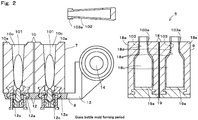
- Fig. 2 is a schematic side view of the glass bottle manufacturing equipment 1 while manufacturing glass bottles 103, with partial omission.
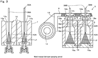
- Fig. 3 is a schematic side view exemplifying a part of the glass bottle manufacturing equipment 1 with the mold release lubricant sprayed, with a partial cross-sectional view and partial omission.
- Fig. 4 is a schematic side view of the first spray portion 30A of a mold release lubricant spraying equipment 4 of the glass bottle manufacturing equipment 1.
- Fig. 5 is a schematic side view of the second spray portion 30B of the mold release lubricant spraying equipment 4 of the glass bottle manufacturing equipment 1.
- Fig. 6 is a schematic side view of a mold release lubricant pump 47A of the first spray portion 30A and of a mold release lubricant pump 47B of the second spray portion 30B, with partial cross-sectional view.
- the glass bottle manufacturing equipment 1 uses a blank mold portion 7 to form gob 101 (a lump of molten glass) supplied by a gob supply mechanism (not shown) into a parison 102. Furthermore, a blow mold portion 9 is used to form the parison 102 into the glass bottle 103. As shown in this embodiment, the glass bottle 103 may be formed using the blow and blow process, or may be formed via the press and blow process. Furthermore, in this embodiment, the manufacturing equipment 1 can form two gobs 101 simultaneously into the glass bottles 103 via each single section 5. Note that the manufacturing equipment 1 is not limited to form two bottles simultaneously in a single section 5. The embodiment may comprise a structure that can simultaneously form glass bottles 103 from one or three or more gobs 101.
- the manufacturing equipment 1 comprises a gob supply mechanism (not shown), a glass bottle manufacturing portion 3, the mold release lubricant spraying equipment 4 to serve as the mold release lubricant application equipment, and a glass bottle manufacturing control portion 6 to control the glass bottle manufacturing portion 3.
- a plurality of sections 5 are formed in the glass bottle manufacturing portion 3.
- 8-12 sections 5 are provided to the glass bottle manufacturing portion 3, which are arranged at substantially even intervals along a predetermined arrangement direction A1.
- Each section 5 comprises the blank mold portion 7, a neck ring portion 8, and the blow mold portion 9.
- the blank mold portion 7 works in correlation with the neck ring portion 8 to form the gob 101 supplied from the gob supply mechanism to form the parison 102.
- the blank mold portion 7 comprises two blank molds 10 for glass bottle forming, and blank mold open/close mechanism 11.
- Each blank mold 10 comprises a pair of split molds 10a and 10b that are positioned across from each other.
- the pair of split molds 10a and 10b which is combined together to form a cavity 10c in which the gob 101 is formed into a parison 102.
- the opening and closing operation of the pair of split molds 10a and 10b of each blank mold 10 is controlled by the blank mold open/close mechanism 11.
- Mold release lubricant L1 is regularly applied to the inner surface of the cavity 10c via the first spray portion 30A of the mold release lubricant spraying equipment 4.
- the mold release lubricant L1 is used to maintain slipperiness between the gob 101 and the blank mold inner surface as well as the releasability of the parison 102 from the blank mold 10.
- a neck ring 12 of the neck ring portion 8 is positioned below the blank mold 10.
- the neck ring portion 8 is provided to form a finish area 103a from the gob 101.
- the neck ring portion 8 is structured so as to transfer the parison 102 formed via the blank mold 10 to the blow mold portion 9.
- the neck ring portion 8 comprises two neck rings 12, a neck ring holder 13 to support the neck rings 12, a rotary shaft 14 to which the neck ring holder 13 is attached, and a neck ring open/close mechanism 15.
- Each neck ring 12 comprises a pair of half cylindrical shaped split molds 12a and 12b that face each other. Combining these split molds 12a and 12b forms the cylindrical shaped neck ring 12. Via a movement of the neck ring open/close mechanism 15, split molds 12a and 12b are appropriately switched between open state that the split molds are separated, and closed state that the split molds are closed together. When forming the gob 101 into the parison 102, a part of the neck ring 12 fits a bottom of the blank mold 10.
- the neck ring holder 13 is an L-shaped arm member. A mounting position of the neck ring holder 13 is attached to the rotary shaft 14 that extends horizontally. Using rotary mechanism 16, the neck ring holder 13 and the neck rings 12 are able to rotate around the central axis of the rotary shaft 14. With this rotation, the neck rings 12 travel between a position at the bottom of the blank mold 10 (position in Fig. 1 ) and a position at the top of the blow mold portion 9 (position in Fig. 3 ).
- the blow mold portion 9 comprises two blow molds 18 for forming glass bottles, two bottom molds 19, and a blow mold open/close mechanism 20.
- Each blow mold 18 forms the glass bottle 103 by working together with the corresponding bottom mold 19 to form the portion of the parison 102 that does not contain the finish area 103a.
- Each blow mold 18 comprises a pair of split molds 18a and 18b.
- the blow mold open/close mechanism 20 opens and closes the pair of 18a and 18b of the blow mold 18. These split molds 18a and 18b are combined to form the blow mold 18.
- the inner surface of the blow mold 18 and upper surface of the bottom mold 19 form a cavity 18c in which a part of the parison 102 other than the finish area 103a are inserted.
- the upper surface of each split mold 18a and 18b of the blow mold 18 is flat surface and structured so as to receive the finish area 103a of the glass bottle 103.
- the upper area of the inner surface of the cavity 18c of the blow mold 18 includes a neck forming area 18d for forming a neck area of the glass bottle 103.
- the center area of the inner surface of the cavity 18c of the blow mold portion 9 contains a shoulder forming area 18e for forming a shoulder area of the glass bottle 103.
- the upper surface of the bottom mold 19 comprises a bottom forming area 19a for forming the bottom of the glass bottle 103.
- a coating layer is formed, such as coated with carbon, on the inner surface of the blow mold 18 and the upper surface of the bottom mold 19.
- mold release lubricant L2 is regularly applied to these inner surfaces with the second spray portion 30B of the mold release lubricant spraying equipment 4. The mold release lubricant L2 is applied to ensure ease of releasability of the glass bottle 103 from the blow mold 18 and the bottom mold 19.
- the parison 102 is formed into the glass bottle 103 by compressed air for forming being supplied from a blow head (not shown) towards the parison 102, the majority of which is placed in the cavity 18c. From there, the glass bottle 103 is taken out from the blow mold 18 with a takeout arm (not shown), subsequently is transferred by a conveyor (not shown).
- a plurality of sections 5 are formed along the arrangement direction A1.
- Each section 5 includes the blank molds 10, the neck rings 12, and the blow molds 18, which are aligned in the direction perpendicular to the arrangement direction A1 in plain view.
- a plurality of blank molds 10 are arranged independently along the arrangement direction A1.
- a plurality of blow molds 18 are arranged independently along the arrangement direction A1.
- Fig. 7 is a block diagram showing a schematic view of the major part of the electric structure of the manufacturing equipment 1.
- the glass bottle manufacturing portion 3 comprising the aforementioned structure is controlled by the glass bottle manufacturing control portion 6.
- the glass bottle manufacturing control portion 6 comprises a computer containing, for example, a CPU (Central Processing Unit), ROM (Read Only Memory), and RAM (Random Access Memory), and a PLC (Programmable Logic Controller) or a sequence circuit and the like.
- a CPU Central Processing Unit
- ROM Read Only Memory
- RAM Random Access Memory
- PLC Programmable Logic Controller
- the glass bottle manufacturing control portion 6 is electrically connected to the gob supply mechanism, and outputs commands to the gob supply mechanism to supply the gobs 101 from the gob supply mechanism to the blank molds 10 and commands to stop supplying the gobs 101 from the gob supply mechanism to the blank molds 10.
- the glass bottle manufacturing control portion 6 is electrically connected to the blank mold open/close mechanism 11, the neck ring open/close mechanism 15, and the blow mold open/close mechanism 20, and controls the open/close operations for these mechanisms 11, 15 and 20.
- the glass bottle manufacturing control portion 6 is electrically connected to the rotary mechanism 16 that rotationally drives the rotary shaft 14, and controls the position of the neck rings 12 by controlling the rotary mechanism 16.
- the mold release lubricant spraying equipment 4 is used to apply these mold release lubricants L1 and L2.
- the mold release lubricant spraying equipment 4 is simply referred to as a spraying equipment 4.
- the spraying equipment 4 comprises the first spray portion (the first application portion) 30A for applying the mold release lubricant L1 for the blank molds 10, to the inner surfaces of the cavities 10c of the blank molds 10, the second spray portion (the second application portion) 30B for applying the mold release lubricant L2 used for the neck rings 12, the blow molds 18, and the bottom molds 19, to the inner surfaces of cavities 12c of the neck rings 12, the upper surfaces of the blow molds 18, and the inner surfaces of the cavities 18c, a spray control portion (the application control portion) 31 for operating the first spray portion 30A and the second spray portion 30B in association with each other, and an operation display portion 32.
- This embodiment is explained using an example of a structure through which the second spray portion 30B applies the mold release lubricant L2 to the inner surfaces of the cavities 12 of the neck rings 12 but this is not a required structure.
- this embodiment may be structured so that the first spray portion 30A applies the mold release lubricant L1 to the inner surfaces of the cavities 12c of the neck rings 12.
- This embodiment is explained using an example of an embodiment through which the mold release lubricant L1 and the mold release lubricant L2 are sprayed via nozzles 38A and nozzles 38B respectively as the lubricant application parts though, this is not a required embodiment.
- this embodiment may be structured so that the mold release lubricant L1 and the mold release lubricant L2 are applied using the lubricant application parts such as a brush in place of the nozzles 38A and the nozzles 38B.
- the structural parameters of the first spray portion 30A are described with a letter "A” in addition to a numerical code and the structural parameters of the second spray portion 30B are described with a letter “B” in addition to a numerical code. Furthermore, the same numerical code is applied to the structural parameters of the first spray portion 30A and the structural parameters of the second spray portion 30B.
- the codes "A” and "B” may be omitted with only the numerical codes indicated.
- the first spray portion 30A and the second spray portion 30B are structured as shown in the plain view shown in Fig. 1 (symmetrical to the direction perpendicular to the arrangement direction A1). Furthermore, excluding the point that the first spray portion 30A sprays the mold release lubricant L1 to the blank molds 10, and the second spray portion 30B sprays the mold release lubricant L2 to the blow molds 18, these structures are identical. Thus, the explanation below mostly refers to as the structure of the first spray portion 30A and omits the explanation of the second spray portion 30B.
- the first spray portion 30A is provided on a plurality of sections 5 in relation to the blank mold portion 7.
- the single first spray portion 30A sprays the mold release lubricant L1 to all the blank mold portions 7.
- the mold release lubricant L1 applied by the first spray portion 30A a mineral oil containing graphite particles as a solid lubricant may be exemplified.
- the first spray portion 30A is structured so as to apply the mold release lubricant L1 to, at least a part of the upper and lower surfaces inside the cavity 10c of the blank mold 10.
- the first spray portion 30A comprises a transport mechanism 33 (the first transport mechanism) A and a spraying unit 34A.
- the transport mechanism 33A is provided to move the spraying unit 34A that includes the nozzles 38A for applying the mold release lubricant L1, among a plurality of blank molds 10 along the arrangement direction A1.
- the transport mechanism 33A is able to position the nozzles 38A of the spraying unit 34A in the side of the blank mold portion 7 in the section 5 where the mold release lubricant L1 is sprayed.
- the transport mechanism 33A comprises a rail 35A, which extends along the arrangement direction A1, base parts 36A that move on the rail 35A, and a transport motor 37A that serves as a drive motor for transmitting a driving force to the base parts 36A in the arrangement direction A1.
- the base parts 36A are provided with the spraying unit 34A.
- the spraying unit 34A is structured so as to spray the mold release lubricant L1 on each section 5 by moving along the arrangement direction A1. Furthermore, in this embodiment, the spraying unit 34A has a monitoring function whether or not an abnormality is occurring in the blank mold portion 7. When not working, the spraying unit 34A is positioned at a designated first standby position P1. In this embodiment, the first standby position P1 is further set outside from the one end of plurality of the sections 5 along the arrangement direction A1. At the first standby position P1, the spraying unit 34A does not face any of sections 5 in a direction that is perpendicular to the arrangement direction A1.
- the spraying unit 34A comprises the nozzles (the first lubricant application parts) 38A that sprays the mold release lubricant L1, a manipulator 39A for changing the position of the nozzles 38A, a mold release lubricant supply portion 40A for supplying the mold release lubricant L1 to the nozzles 38A, an abnormal spray detecting portion 41A, and a glass residual detecting portion 42A.
- the nozzles 38A are used to spray the mold release lubricant L1.
- the nozzles 38A are formed in a shape of thin, long rods. Note that the nozzles 38A are does not necessarily to be a thin, long rod shape.
- the number of nozzles 38A provided is the same as the number of blank molds 10 in a single section 5. In this embodiment, two are provided. Each nozzle 38A is formed to have a length that at least enables the tip of the nozzle 38A to be inserted into the cavity 10c.
- Each nozzle 38A may spray the blank mold 10 with the mold release lubricant L1 while being raised by the manipulator 39A, or being lowered, or may spray the mold release lubricant L1 after being inserted in the cavity 10c in a stop state.
- Spray holes 43A are formed on the tip of nozzle 38A.
- a diameter of the spray holes 43A are structured, for example, to be approximately 1mm or smaller.
- the mold release lubricant L1 is sprayed from the spray holes 43A to form, for example, a full cone spray pattern.
- the mounting part of the nozzle 38A is fixed onto the hollow shaft shaped manifold 45A.
- a channel for the mold release lubricant L1 is formed inside the manifold 45A.
- the mold release lubricant L1 passes through the manifold 45A into the channel of the corresponding nozzle 38A and is sprayed from the corresponding spray holes 43A.
- the manipulator 39A is used to change the position of nozzles 38A with respect to the blank molds 10 as well as to maintain the position of the nozzles 38A.
- the manipulator 39A is formed, for example, using a multiple joint robot with multiple axes.
- the manipulator 39A in this embodiment, can cause the nozzles 38A to rotate around each joint, and to shift parallel to direction of X, Y, and Z axes that are mutually orthogonal.
- the manipulator 39A can at least cause the nozzles 38A to enter and exit the cavities 10c of the blank molds 10, thus there are no limitations on a specific structure.
- the manifold 45A is fixed to the tip of the manipulator 39A. As a result, the manipulator 39A and the manifold 45A can change the position of the nozzles 38A.
- the mold release lubricant supply portion 40A is provided to supply the mold release lubricant L1 to the nozzles 38A via the manifold 45A.
- the mold release lubricant supply portion 40A comprises a mold release lubricant tank 46A and the mold release lubricant pump 47A.
- Compressed air is supplied to a mold release lubricant regulator 54A (to be described later) of the mold release lubricant pump 47A and an air regulator 53A, from an air compressor or other compressed air supply source (not shown) installed at a distance from the mold release lubricant supply portion 40A.
- the mold release lubricant regulator 54A is connected to the mold release lubricant tank 46A.
- the mold release lubricant tank 46A is a tank for filling the mold release lubricant L1.
- the air pressure from a compressed air supply source is applied to the mold release lubricant L1 contained in the mold release lubricant tank 46A.
- the mold release lubricant pump 47A is provided to supply the mold release lubricant L1 to the nozzles 38A at a predetermined pressure.
- the mold release lubricant pump 47A is a volumetric pump, which is a kind of reciprocating pump.
- the mold release lubricant pump 47A draws in and discharges the mold release lubricant L1 by using supplied compressed air as a dynamic fluid.
- the mold release lubricant pump 47A comprises a check valve 49A, a three-way coupling joint 50A, an on/off valve 51A, a syringe 52A, the air regulator 53A, and the mold release lubricant regulator 54A.
- the check valve 49A is connected to the mold release lubricant tank 46A and the three-way coupling joint 50A.
- the check valve 49A allows movement of the mold release lubricant L1 from the mold release lubricant tank 46A to the three-way coupling joint 50A but prevents reverse flow of the mold release lubricant L1 from the three-way coupling joint 50A to the mold release lubricant tank 46A.
- the three-way coupling joint 50A is a pipe connecting the check valve 49A (the mold release lubricant tank 46A), the syringe 52A, and the nozzles 38A (hose 55A).
- the on/off valve 51A for example, is a needle valve and the spray control portion 31, which controls on and off of pilot air supply to the needle valve, controls the on/off operation of the on/off valve 51A.
- the on/off valve 51A is connected to the manifold 45A via, for example, a flexible hose 55A.
- the mold release lubricant L1 passing through the on/off valve 51A passes through the hose 55A and the manifold 45A to reach the nozzles 38A and is sprayed from the spray holes 43A of the nozzles 38A.
- the syringe 52A alternatively suctions or discharges the mold release lubricant L1 by compressed air.
- the syringe 52A is a material that is formed into a thin, long cylindrical shape, in which compressed air is introduced via the air regulator 53A, and the mold release lubricant L1 is introduced via the mold release lubricant regulator 54A and the mold release lubricant tank 46A.
- the abnormal spray detecting portion 41A for example, optically monitors the syringe 52A for a state of the mold release lubricant L1.
- the syringe 52A is made from a material with translucency.
- the upper end of the syringe 52A is connected to the air regulator 53A.
- the compressed air enters and exits the syringe 52A through the upper end.
- the lower end of the syringe 52A is connected to the mold release lubricant tank 46A via the three-way coupling joint 50A.
- the mold release lubricant L1 enters and exits the syringe 52A through this lower end.
- the first upper limit P11A of the mold release lubricant L1 inside the syringe 52A is the highest fluid level (upper surface) when the mold release lubricant L1 is taken into the syringe 52A.
- the first lower limit P14A of the mold release lubricant L1 in the syringe 52A is the fluid level at the time of completion of discharge of the mold release lubricant L1 from the syringe 52A to the nozzles 38A. This is the lowest surface level of the mold release lubricant L1 inside the syringe 52A.
- the first lower limit P14A is the level at which the mold release lubricant L1 is constantly present.
- the air regulator 53A is provided to adjust the pressure of compressed air supplied into the syringe 52A from the compressed air supply source.
- the air regulator 53A is an electro pneumatic regulator and is controlled by the spray control portion 31.
- the spray control portion 31 controls the air regulator 53A to control the supply of compressed air to the syringe 52A and discharge of compressed air from the syringe 52A. Furthermore, the spray control portion 31 controls the on/off operation of the on/off valve 51A. Through this implementation, the spray control portion 31 controls supply of the mold release lubricant L1 from the mold release lubricant pump 47A to the nozzles 38A.
- the spray control portion 31 closes the on/off valve 51A and controls the air regulator 53A to keep the air pressure inside the syringe 52A lower than the liquid pressure of the mold release lubricant inside the syringe 52A.
- the mold release lubricant L1 passes through the check valve 49A and the three-way coupling joint 50A to flow into the syringe 52A.
- the spray control portion 31 controls the air regulator 53A to keep the air pressure inside the syringe 52A higher than the liquid pressure inside the syringe 52A.
- the check valve 49A closes to stop the flow of the mold release lubricant L1 to the syringe 52A.
- the spray control portion 31 When spraying the mold release lubricant L1, the spray control portion 31 opens the on/off valve 51A. As a result, compressed air, whose pressure is adjusted by the air regulator 53A, pushes out the mold release lubricant L1 in the syringe 52A to be sprayed through the spray holes 43A. After spraying for a predetermined time period, the spray control portion 31 closes the on/off valve 51A. This completes the spraying of the mold release lubricant L1 from the mold release lubricant pump 47A.
- the mold release lubricant pump 47A conducts the mold release lubricant L1 spraying operation as a single cycle of the abovementioned intake operation and discharge operation of the mold release lubricant.
- the abnormal spray detecting portion 41A is provided to detect any abnormality in the first spray portion 30A.
- the abnormal spray detecting portion 41A is structured so as to detect the mold release lubricant L1 to check for any abnormality in spraying the mold release lubricant L1 in the first spray portion 30A.
- the abnormal spray detecting portion 41A comprises first photoelectric sensors 56A and 57A that detect light.
- Each first photoelectric sensor 56A and 57A is fixed to the outer circumference of the syringe 52A.
- Each first photoelectric sensor 56A and 57A comprises a lighting portion and a detecting portion.
- each photoelectric sensor 56A and 57A outputs a detection signal that is based on the strength of the light detected by the detecting portion, to the spray control portion 31. It is acceptable if each photoelectric sensor 56A and 57A outputs a signal based on the strength of the light detected by the detecting portion as a detected signal, and this implementation is not limited to any specific principle.
- the first photoelectric sensor 56A is positioned near the first upper limit P11A and near the first upper detecting position P12A below the first upper limit P11A, and outputs different detection signals depending on when the mold release lubricant L1 is present at the first upper detecting position P12A, or not.
- the first photoelectric sensor 57A is positioned near the first lower limit P14A and near the first lower detecting position P13A above the first lower limit P14A, and outputs different detection signals depending on when the mold release lubricant L1 is present at the first lower detecting position P13A, or not.
- the first upper detecting position P12A and the first lower detecting position P13A are arranged between the first upper limit P11A and the first lower limit P14A in the longitudinal direction of the syringe 52A.
- This is a measure against a concave meniscus to be formed on the mold release lubricant L1 liquid surface level via an interaction between the mold release lubricant L1 and the syringe 52A.
- This arrangement eliminates the impact of the meniscus caused by the interaction between the mold release lubricant L1 and the syringe 52A.
- the first photoelectric sensors 56A and 57A operate the non-contact detection of the mold release lubricant L1 through the syringe 52A that is comprised of a light-transmitting portion.
- a sensor with a structure for outputting a detection signal depending on the existence of the mold release lubricant L1 may be used in place of the first photoelectric sensors 56A and 57A.
- An exemplification of an abnormality that could occur in the spraying unit 34A is the sprayed amount of the mold release lubricant L1 from the spray holes 43A of the nozzle 38A, which diverges from a design value.
- the abnormality can be exemplified as (1) malfunctions in the compressed air supply source or the on/off valve 51A, the regulators 53A and 54A, or the check valve 49A, spray pressure changes due to cracks in release lubricant L1 piping or compressed air piping, (2) changes in spray time due to the on/off valve 51A operating errors, (3) changes in mold release lubricant temperature (viscosity) due to air temperature change, and (4) changes of the spray area of the mold release lubricant L1 due to clogs in the spray holes 43A of the nozzle 38A.
- abnormalities occurring in the first spray portion 30A are detected by the abnormal spray detecting portion 41A. Specifically, if an abnormality in mold release lubricant discharge occurs to the syringe 52 of the mold release lubricant pump 47A, after the mold release lubricant L1 discharge operation starts by the mold release lubricant pump 47A, it is perceivable that the first mold release lubricant L1 liquid surface does not reach the first lower detecting position P13A within a predetermined time.
- the spray control portion 31 detects these types of abnormalities based on the presence of the mold release lubricant L1 detected by the first photoelectric sensors 56A and 57A.
- the spraying unit 34A has a structure for detecting the spray abnormality of the mold release lubricant described above as well as a structure for detecting abnormal residual glass lumps occurring to the blank mold 10. Specifically, the spraying unit 34A comprises the glass residual detecting portion 42A.
- the glass residual detecting portion 42A is provided to detect whether or not a gob 101 or parison 102 remains in the form of a lump of glass inside the cavity 10c of each blank mold 10.
- the glass residual detecting portion 42A is one example of "a sensor" in this invention.
- the glass residual detecting portion 42A is, for example, formed using a CCD camera (Charge Couple Device Camera) or other solid body imaging element for photographing the cavity 10c, and photographs the inner surface of each cavity 10c in the section 5 at which the spraying unit 34A is arranged. Note that it is acceptable as long as the glass residual detecting portion 42A detects a lump of glass in a molten state or at a high temperature close to a molten state, the sensor may be an infrared detection device and the like.
- a structure of the second spray portion 30B is described. Note that, as described previously, the structure of the second spray portion 30B is the same as the first spray portion 30A, thus the explanation of the second spray portion 30B has been simplified.
- the mold release lubricant L2 applied by the second spray portion 30B a mineral oil containing graphite particles as a solid lubricant may be exemplified.
- the second spray portion 30B is structured so as to apply the mold release lubricant L2 to, at least a part of the upper and lower surfaces inside the cavity 18c of the blow mold 18, and inside the cavity 12c of the neck ring 12.
- the second spray portion 30B comprises a transport mechanism 33B and a spraying unit 34B.
- the transport mechanism 33B is provided to move the spraying unit 34B, which includes the nozzles 38B for applying the mold release lubricant L2, among the plurality of blow molds 18 along the arrangement direction A1.
- the transport mechanism 33B is able to arrange the nozzles 38B of the spraying unit 34B in the side of the blow mold portion 9 in the section 5 where the mold release lubricant L2 is sprayed.
- Each nozzle 38B is formed to have a length that at least enables the tip of the nozzle 38B to be inserted into the cavity 18c.
- the mold release lubricant L2 from spray holes 43B of the nozzle 38B is sprayed on the corresponding neck ring 12, blow mold 18, and bottom mold 19.
- the spraying of the mold release lubricant L2 on at least one of the neck ring 12, blow mold 18, and the bottom mold 19, may be collectively referred to as "spraying the mold release lubricant L2 on the blow mold 18".
- a manipulator 39B can at least causes the nozzle 38B to enter and exit the cavity 12c of the neck ring 12 and the cavity 18c of the blow mold 18, and there are no limitations on a specific structure.
- a glass residual detecting portion 42B is provided to detect whether or not a parison 102 or a glass bottle 103 remains in the cavity 18c of the blow mold 18 as a lump of glass.
- the glass residual detecting portion 42B is one example of "a sensor" in this invention.
- the glass residual detecting portion 42B is formed from, for example, a CCD camera or other solid body imaging element for photographing the cavity 18c, and photographs the inner surface of each cavity 18c in the section 5 where the spraying unit 34B is arranged.
- the spray control portion 31 comprises a configuration for outputting a specific output signal based on a specific input signal and may be configured, for example, via a programmable controller (PLC).
- PLC programmable controller
- the spray control portion 31 may also be configured using a computer comprising a central processing unit (CPU), random access memory (RAM), and read only memory (ROM), and may be configured using a Field Programmable Gate Array (FPGA) or other programmable logic device.
- the spray control portion 31 is arranged, for example, on the side of the first section 5 of the glass manufacturing portion 3, and is electrically connected to each portion wirelessly or via an electric wire (not shown) to the first spray portion 30A and the second spray portion 30B.
- the spray control portion 31 is connected to the glass bottle manufacturing control portion 6, the first spray portion 30A, the second spray portion 30B, and the operation display portion 32, and is able to communicate with these portions 6, 30A, 30B, and 32.
- the glass bottle manufacturing control portion 6 outputs a signal to the spray control portion 31 at specific intervals.
- the Spray control portion 31 uses this signal to determine whether or not section 5 is working or stopped, and to adjust the timing of the application operation.
- the connection relationship between the spray control portion 31 and the first spray portion 30A is to be described.
- the spray control portion 31 is connected to the transport motor 37A of the first spray portion 30A, the manipulator 39A, the abnormal spray detecting portion 41A (the first photoelectric sensors 56A and 57A), the glass residual detecting portion 42A, and the mold release lubricant pump 47A (the on/off valve 51A, the air regulator 53A).
- the spray control portion 31 is connected to a transport motor 37B of the second spray portion 30B, the manipulator 39B, an abnormal spray detecting portion 41B (the photoelectric sensors 56B and 57B), the glass residual detecting portion 42B, and the mold release lubricant pump 47B (the on/off valve 51B, air regulator 53B).
- the spray control portion 31 is configured so as to control the positioning of the spraying unit 34A in the arrangement direction A1 by the transport mechanism 33A (cyclic moving operation of the nozzles 38A to each section 5), the positioning of the nozzles 38A by the manipulator 39A, and the supply of the mold release lubricant L1 from the mold release lubricant pump 47A to the nozzles 38A (nozzles 38A spraying operation).
- the spray control portion 31 is configured so as to control the positioning of the spraying unit 34B in the arrangement direction A1 by the transport mechanism 33B (cyclic moving operation of the nozzles 38B to each section 5), the positioning of the nozzles 38B by the manipulator 39B, and the supply of the mold release lubricant L2 from the mold release lubricant pump 47B to the nozzles 38B (nozzles 38B spraying operation).
- the spray control of the mold release lubricants L1 and L2 from the nozzles 38A and 38B to the corresponding blank molds 10 and blow molds 18 (the neck rings 12 and the bottom molds 19) can be conducted by controlling the spray amount from the nozzles 38A and 38B, by controlling the speed of rising and descending the nozzles 38A and 38B with the spray amount fixed, and by controlling the spray timing of the mold release lubricants L1 and L2 from the nozzles 38A and 38B.
- the desired application can also be achieved by controlling the ON/OFF setting of the mold release lubricants L1 and L2 from the nozzles 38A and 38B.
- the spray control portion 31 controls the transport mechanisms 33A and 33B, the manipulators 39A and 39B, the mold release lubricant pumps 47A and 47B, as well as monitors a spray abnormality of the mold release lubricants L1 and L2 via the abnormal spray detecting portions 41A and 41B. Specifically, the spray control portion 31 outputs a specific command signal to the transport motors 37A and 37B of the transport mechanisms 33A and 33B to drive the transport motors 37A and 37B to arrange the spraying units 34A and 34B, which includes the nozzles 38A and 38B, at designated positions along the arrangement direction A1 accordingly.
- the spray control portion 31 outputs a specific command signal to joint motors of the manipulators 39A and 39B to drive the articulated joint of the corresponding articulation motors.
- the spray control portion 31 changes the position of the nozzles 38A and 38B along with the tips of the manipulators 39A and 39B.
- the spray control portion 31 controls the on/off operation of the on/off valves 51A and 51B, and the air pressure inside the syringes 52A and 52B.
- the spray control portion 31 cooperatively controls the mold release lubricant pumps 47A and 47B and the corresponding manipulators 39A and 39B.
- This control enables the nozzles 38A and 38B to be moved in the vertical direction with respect to the corresponding blank molds 10 and blow molds 18, while also spraying the mold release lubricants L1 and L2 from the nozzles 38A and 38B to corresponding locations on the blank molds 10, the blow molds 18, the bottom molds 19, and the neck molds 12.
- the application range of the mold release lubricants L1 and L2 in the vertical direction may be set arbitrarily.
- the spray control portion 31 controls the position of the nozzles 38A and 38B by the manipulators 39A and 39B, and controls the mold release lubricant pumps 47A and 47B. This control enables the coating thickness of the mold release lubricants L1 and L2 applied to each portion in the vertical direction to be even or variable.
- the spray control portion 31 notifies an abnormality alarm when an abnormality occurs to either of the nozzle 38A or 38B.
- the spray control portion 31 is further configured so as to monitor abnormalities of each blank mold 10 and each blow mold 18.
- an abnormality alarm signal is output to the glass bottle manufacturing control portion 6, indicating that an abnormality is detected at the section 5.
- the first spray portion 30A and the second spray portion 30B comprising the above structure is controlled by the spray control portion 31 based on command signals output from the operation display portion 32.
- the operation display portion 32 is installed on a chassis of the spray control portion 31.
- the operation display portion 32 includes a touch panel 66.
- the touch panel 66 displays a screen for the operator to conduct touch-based operations.
- the touch panel 66 display content is configured so as to be changed based on commands received from the spray control portion 31 and commands received from an operator.
- the operation display portion 32 displays an operating button on the touch panel 66 for the operator to input controls. Pressing the specific operating buttons displayed on the touch panel 66 sends specific commands to the spray control portion 31.
- the touch panel 66 is configured so as to display specific indication other than the operating buttons.
- the touch panel 66 includes a structure for conducting the following settings (interface screen and signal processing). Specifically, the following settings are included.
- buttons are displayed on the touch panel 66.
- An operator manipulates the button of the relevant operation.
- the spray control portion 31 recognizes which section 5 conducts glass bottle manufacturing. Furthermore, the spray control portion 31 puts the settings of the dimensions for the blank mold 10 and the blow mold 18, the application range for the blank mold 10 and the blow mold 18, and the movement speed settings for nozzles 38A and 38B, and the spray pressure for 38A and 38B, to the input values.
- buttons are displayed on the touch panel 66.
- the operator manipulates the button of the relevant operation.
- the spray control portion 31 recognizes which section 5 is a subject of the mold release lubricants L1 and L2 spraying.
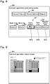
- the touch panel 66 displays a regular cycle lubricant application setting screen 82.
- the regular cycle lubricant application setting screen 82 includes lubricant application cycle time setting buttons 86 and spray location setting buttons 87.
- Lubricant application cycle time setting buttons 86 are buttons for setting the interval for starting to spray the mold release lubricants L1 and L2 for the single or multiple sections 5 specified on touch panel 66. When an operator presses any kinds of the lubricant application cycle time setting buttons 86, the spray control portion 31 sets the time corresponding to the pressed button as the time for a single cycle.
- the spray location setting buttons 87 are provided to specify the spray location of the mold release lubricant L1 and L2.
- the spray location setting buttons 87 include a blank mold setting panel button 88, a neck ring setting panel 89, and blow mold setting panel buttons 90.
- a blank mold setting panel button 88 is the button for generating the command for the first spray portion 30A to spray the mold release lubricant L1 to the inner surface of the cavity 10c of the blank mold 10.
- the spray control portion 31 controls the first spray portion 30A so that it sprays the mold release lubricant L1 to the inner surface of the blank mold 10.
- a neck ring setting panel button 89 is a button for generating the command for the first spray portion 30A to spray the mold release lubricant L1 to the inner surface of the cavity 12c of the neck ring 12.
- the spray control portion 31 controls the spray portion 30B so that it sprays the mold release lubricant L2 to the neck ring 12.
- a command may be generated for the first spray portion 30A to spray the mold release lubricant L1 to the inner surface of the cavity 12c of the neck ring 12, by pressing the neck ring setting panel button 89.
- the blow mold setting panel buttons 90 are buttons for generating the command for the spray portion 30B to spray the mold release lubricant L2 to the inner surface of the cavity 18c of the blow mold portion 9.
- the blow mold setting panel buttons 90 include a blow mold upper surface setting panel button 90a, a neck area setting panel button 90b, and a shoulder/bottom area setting panel button 90c.
- the blow mold upper surface setting panel button 90a is a button for generating the command to spray the mold release lubricant L2 to the upper surface of the blow mold 18.
- the spray control portion 31 controls the second spray portion 30B so that it sprays the mold release lubricant L2 to the upper surface of the blow mold 18.
- the neck area setting panel button 90b is a button for generating the command to spray the mold release lubricant L2 to the neck forming area 18d of the blow mold 18.
- the spray control portion 31 controls the second spray portion 30B so that it sprays the mold release lubricant L2 to the neck forming area 18d of the blow mold 18.
- the shoulder/bottom area setting panel button 90c is a button for generating the command to spray the mold release lubricant L2 to the shoulder forming area 18e of the blow mold 18, and the upper surface of the bottom mold 19 (the bottom forming area 19a).
- the spray control portion 31 controls the second spray portion 30B so that it sprays the mold release lubricant L2 to the shoulder forming area 18e of the blow mold 18 and the upper surface of the bottom mold 19. Note that the abovementioned structure is one example and depending on programming of the spray control portion 31, the settings may be more detailed.
- the settings set via the regular cycle lubricant application setting screen 82 are settings for the mold release lubricant spraying operations conducted repeatedly on all operating sections regularly by the spray portions 30.
- Fig. 8 while explaining spray location settings for the regular cycle lubricant application operation.
- spray location settings for the temporary lubricant application operation that is the mold release lubricant spraying operation conducted temporarily (one-time) by the spray portions 30, are input in the same way as spray location settings for the regular cycle lubricant application.
- Operations conducted in the temporary lubricant application process allow the selection of the application location for each section and only operates application on the selected section.
- Basic operations are the same as the regular cycle lubricant application.
- the explanation of settings for the temporary lubricant application operation is omitted.
- the monitoring mode is set by operating the touch panel 66. This monitoring mode is set by an operator pressing the monitoring mode settings button (not shown). When this monitoring mode is selected, the spray control portion 31 repeatedly moves to each section in order until the time of the regular cycle lubricant application to monitor via sensors. For example, the monitoring mode to be described later (Steps G1-G10 described below) may be operated regularly.
- Fig. 9 is a diagram showing a lubricant application history screen 84.
- the lubricant application history screen 84 is a screen for displaying the application history for the spraying the mold release lubricants L1 and L2 by the first spray portion 30A and the second spray portion 30B onto the blank molds 10 and the blow molds 18.
- the lubricant application history screen 84 displays, for example, the mold release lubricant application history for each cycle of the mold release lubricant spraying operation.
- Fig. 9 shows images of the blank mold lubricant application history and the blow mold lubricant application history.
- each operation is conducted by an operator pressing the relevant button displayed on the touch panel 66.
- the spray control portion 31 is configured so as to execute an application mode wherein both the first spray portion 30A and the second spray portion 30B apply the mold release lubricant L, and an application mode wherein either of the first spray portion 30A or the second spray portion 30B applies the mold release lubricant L.
- Examples of the operation by the spray portion 30A are presented such as (i) regular cycle spraying operation for the mold release lubricants L1 and L2 based on the settings input in the regular cycle lubricant application setting screen 82 (see Fig. 8 ), (ii) temporary lubricant spraying operation of the mold release lubricants L1 and L2 based on the settings input in the temporary lubricant application setting screen (not shown), and (iii) abnormality detecting operations in the monitoring mode.
- the above operation (i) is also referred to as the regular cycle lubricant application operation.
- the above operation (ii) is also referred to as a temporary lubricant application operation.
- the settings input in the regular cycle lubricant application setting screen 82 include (i-1), a simultaneous mold release lubricant spraying operation conducted by both the first spray portion 30A and the second spray portion 30B, and (i-2), a mold release lubricant spraying operation conducted by either of the first spray portion 30A or the second spray portion 30B.
- the settings input in the temporary lubricant application setting screen include (ii-1), a simultaneous mold release lubricant spraying operation conducted by both the first spray portion 30A and the second spray portion 30B, and (ii-2), a mold release lubricant spraying operation conducted by either of the first spray portion 30A or the second spray portion 30B.
- the regular cycle lubricant application operation, (ii) the temporary lubricant application operation, and (iii) the abnormality detecting operation are explained below in order.
- Figs. 10 to 11 are flow charts explaining one example of the operations conducted by (i-1) both the first spray portion 30A and the second spray portion 30B during the mold release lubricant spraying operation as part of (i) the regular cycle lubricant application operation. Note that the following explanation refers to the flow charts as well as diagrams other than the flow charts.
- the spray control portion 31 starts operations after reading data, which is set by operating the operation display portion 32, specifying subjects of the mold release lubricant application (the sections 5, blank molds 10, and blow molds 18).
- the spray control portion 31 drives the transport motors 37A and 37B to start to move the spraying units 34A and 34B towards the set section 5 (step A1). For example, as shown in Fig. 1 , by controlling of the spray control portion 31, the spraying units 34A and 34B are transported from the first standby positions P1 to the section 5 that is designated at the beginning (in Fig. 1 , this is the first section).
- the spray control portion 31 transports the spraying units 34A and 34B to the section 5, which is the closest to the section 5 whose mold release lubricant spraying operation is completed, among the sections 5 to which the mold release lubricant is not applied yet, and for which the regular cycle lubricant application operation is specified.
- the nozzles 38A and 38B are manipulated by the manipulators 39A and 39B and arranged at the second standby positions P2A and P2B as positions set outside from the corresponding the blank molds 10 and the blow molds 18.
- the nozzles 38A and 38B are arranged on the corresponding base parts 36A and 36B so that the nozzles 38A and 38B avoid contacting the base parts and the like, of each section 5 when moving to the spraying units 34A and 34B in the arrangement direction A1.
- the spray control portion 31 operates the spray portions 30A and 30B to apply the mold release lubricants L1 and L2 to at least one of the sections 5. Furthermore, spray control portion 31 controls the spray portion 30A and the spray portion 30B so that the two spray portions 30A and 30B are positioned at the same section 5.
- the spray control portion 31 determines whether or not the designated section 5 is operating the glass bottle manufacturing (Step A2). When the spray control portion 31 does not receive a signal from the glass bottle manufacturing control portion 6 indicating that the designated section 5 is operating the glass bottle manufacturing, in other words, when the designated section 5 is not conducting the glass bottle manufacturing (NO for Step A2), it conducts Step A3. Specifically, the spray control portion 31 changes the target section 5 to the next section 5 of said designated section 5 (section 5 designated by operating the touch panel 66). In this case, the spray control portion 31 operates Step A3 and then retries the Step A2.
- the spray control portion 31 determines that the designated section 5 operates glass bottle manufacturing, in other words, when it receives a signal indicating that the designated section 5 is operating the glass bottle manufacturing from the glass bottle manufacturing control portion 6(YES in Step A2), it controls the transport motors 37A and 37B to stop the spraying units 34A and 34B in front of the designated section 5 (Step A4).
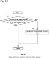
- Fig. 12 is a flow chart showing an example of the spray confirmation equipment diagnosis before spraying (Step A5).
- This spray confirmation equipment diagnosis before spraying is one example of the "inspection mode to check for abnormalities" of this invention, and is operated before the mold release lubricant application process.
- the spray control portion 31 determines whether or not both the photoelectric sensors 56A and 57A of the abnormal spray detecting portion 41A are detecting the mold release lubricant L1 (Step C1). For example, if light from the lighting portion to the detecting portion is blocked for both the photoelectric sensors 56A and 57A due to the mold release lubricant L1 filled in the syringe 52A, the spray control portion 31A determines that the photoelectric sensors 56A and 57A are detecting the mold release lubricant L1 (YES in step C1). In other words, the spray control portion 31 determines that the necessary amount of mold release lubricant is built up in the syringe 52A of the mold release lubricant pump 47A.
- Step C1 the spray control portion 31 completes the spray confirmation equipment diagnosis before spraying (Step A5).
- Step C1 the control portion 31 displays that an abnormality occurs to the mold release lubricant pump 47A, on the touch panel 66 and cancels the lubricant application operation (Step C2).
- the abnormal spray detecting portion 41A detects a spray abnormality (NO in Step C1)
- the spray control portion 31 determines that an abnormality occurs to the mold release lubricant pump 47A.
- the spray control portion 31 cancels all lubricant application operation, which could result in a leak, and moves both the spraying units 34A and 34B to the first standby positions P1 (Step C2). At this time, the spray control portion 31 displays an alarm on the touch panel 66 to notify the abnormality. This completes the spray confirmation equipment diagnosis before spraying.
- the photoelectric sensors 56B and 57B operate a diagnosis of the mold release lubricant pump 47B.
- the mold release lubricant pump 47B diagnosis using the photoelectric sensors 56B and 57B is the same as the mold release lubricant pump 47A diagnosis using the photoelectric sensors 56A and 57A (Step C1, C2).
- a detailed explanation of the mold release lubricant pump 47B diagnosis process using the photoelectric sensors 56B and 57B is omitted.
- the spray control portion 31 outputs a swab request signal (signal requesting to transit from the glass bottle manufacturing cycle to the swab cycle for the section 5 in which the mold release lubricant spraying operation is conducted) (Step A6) to the glass bottle manufacturing control portion 6.
- the glass bottle manufacturing cycle and the swab cycle are the cycles configured in the glass bottle manufacturing portion 3, which includes the blank molds 10, the neck rings 12, and the blow molds 18.
- the glass bottle manufacturing cycle is the cycle for forming the glass bottles 103 in the glass bottle manufacturing portion 3.
- the swab cycle is an operating cycle that differs from the glass bottle manufacturing cycle, in which the gob 101 is not charged into the blank mold 10.
- the spray control portion 31 conducts glass residual detecting operation (Step A7) after outputting the swab request signal.
- This mold abnormality detecting operation is one example of the "inspection mode to check abnormalities" of this invention, and is conducted before the mold release lubricant application operation.
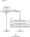
- Fig. 13 is a flow chart explaining one example of processing of the glass residual detecting operation.
- the spray control portion 31 determines whether or not a lump of glass (gob 101 or parison 102) remains inside the cavity 10c of each blank mold 10, which the mold release lubricant is sprayed (Step D1).
- the spray control portion 31 reads image data obtained by the glass residual detecting portion 42A capturing an image of the cavity 10c of each blank mold 10, which the mold release lubricant is sprayed.
- this image data is collated with predetermined data obtained by modeling the lump of glass, and if the degree of coincidence of these data is less than a predetermined value, the spray control portion 31 determines that the lump of glass (gob 101 or parison 102) does not exist inside the cavity 10c described above (NO in step D1).
- the spray control portion 31 finishes the residual abnormality detecting process and confirms the reception of the swab cycle transition signal (Step A8).
- Step D1 the image data captured by the glass residual detecting portion 42A is collated with predetermined data, and if the degree of coincidence of these data is more than the predetermined value, the spray control portion 31 determines that the lump of glass (gob 101 or parison 102) exists in the cavity 10c described above (YES in step D1). That is, the glass residual detecting portion 42A detects a lump of glass. Then, the spray control portion 31 determines that an abnormality occurs, and displays on the touch panel 66 that the lump of glass remains in the blank mold 10 (Step D2).
- Step D2 When the alarm display appears (Step D2), the spray control portion 31 outputs a signal to the glass bottle manufacturing control portion 6 requesting to stop the glass bottle manufacturing operation in the section 5 at which the spraying units 34A and 34B are arranged (Step D3). As a result, the glass bottle manufacturing operation in the section 5 stops.
- the spray control portion 31 stops spraying the mold release lubricant onto the glass bottle manufacturing portion 3 by the spraying units 34A and 34B (Step D4). Then, the spray control portion 31 drives the transport mechanisms 33A and 33B to move the spraying units 34A and 34B to the first standby positions P1 (Step D5). As a result, the mold release lubricant spraying operation is suspended halfway.
- the process for the blow molds 18 is subsequent to the process of the blank molds 10. Therefore, the blow molds 18 enters the swab cycle, one cycle later than the cycle of the blank molds 10.
- a lump of glass (parison 102 or gob 103) remains inside the cavity 18c of each blow mold 18, which the mold release lubricant is sprayed.
- Processing of the glass residual detecting for the blow molds 18 is the same as processing of the glass residual detecting for the blank molds 10. Thus, a detailed explanation of processing of the glass residual detecting for the blow molds 18 is omitted.
- the spray control portion 31 determines whether or not a swab cycle transition signal is received from the glass bottle manufacturing control portion 6 (Step A8).
- the swab cycle transition signal is a signal generated from the glass bottle manufacturing control portion 6 when the glass bottle manufacturing control portion 6 starts executing the swab cycle.
- Step A11 When the spray control portion 31 receives the swab cycle transition signal from the glass bottle manufacturing control portion 6 (YES in Step A8), the mold release lubricant spraying operation is conducted (Step A11). On the other hand, after the spray control portion 31 outputs the swab request signal, if the swab cycle transition signal is not received from the glass bottle manufacturing control portion 6 (NO in Step A8 and YES in Step A9) even after a certain amount of time elapsing, an alarm is displayed on the touch panel 66 and an abnormality is notified (Step A10). Afterward, processing of the Step A3 is operated. In Step A3, the spray control portion 31 drives the transport motors 37A and 37B to move the spraying units 34A and 34B towards the next section 5 set in the settings.
- the spray control portion 31 when the spray control portion 31 receives the swab cycle transition signal (YES in Step A8), it sprays the mold release lubricant (Step A11). That is, the spray control portion 31 causes the spray portions 30A and 30B to spray the mold release lubricant when the glass bottle manufacturing portion 3 is in the swab cycle.
- the spray control portion 31 is triggered by receiving the swab cycle transition signal from the glass bottle manufacturing portion 3 to cause the spray portions 30A and 30B to start the mold release lubricant L1 and L2 spray operation.
- the spray control portion 31 operates the mold release lubricant spraying operation on the blank molds 10 and then conducts the mold release lubricant spraying operation on the blow molds 18. That is, when applying the mold release lubricant L to both the blank molds 10 and the blow molds 18 at the same section 5, the spray control portion 31 applies the mold release lubricant L1 to the blank molds 10 via the first spray portion 30A, and applies the mold release lubricant L2 to the blow molds 18 via the second spray portion 30B.
- the spray control portion 31 first inserts the nozzles 38A from the second standby position P2A on the base parts 36A into the corresponding cavities 10c of the blank molds 10. Subsequently, the spray control portion 31 sprays the mold release lubricant L1 on the inner surface of the cavities 10c of the blank molds 10 by driving the mold release lubricant pump 47A while moving the nozzles 38A in the vertical direction. Then, when the spraying operation of the mold release lubricant L1 is completed, the spray control portion 31 moves the nozzles 38A to the second standby position P2A on the base parts 36A.
- the spray control portion 31 inserts the nozzles 38B into the cavities 18c of the corresponding blow molds 18 from the second standby position P2B on the second base 36B. Then, the spray control portion 31 sprays the mold release lubricant L2 by moving the nozzles 38B in the vertical direction by driving the mold release lubricant pump 47B. At this time, the spray control portion 31 sprays the mold release lubricant L2 on locations set by the regular cycle lubricant application setting screen 82, among the inner surfaces of the cavities 12c of the neck rings 12, the upper surfaces of the cavities 18c of the blow molds 18, the inner surfaces of the cavities 18c, and the bottom forming areas 19a. When the spraying operation of the mold release lubricant L2 is completed, the spray control portion 31 moves the nozzles 38B to the second standby position P2B on the base parts 36B.
- Step A11 The above describes one example of the mold release lubricant spraying operation.
- the spray control portion 31 outputs a swab cycle release request signal to the glass bottle manufacturing control portion 6 (Step A12). Receiving this signal, the glass bottle manufacturing control portion 6 returns the setting from the swab cycle to the glass bottle manufacturing cycle and restarts the glass bottle manufacturing operation in the section 5 in which the mold release lubricant spraying operation by the spraying units 34A and 34B is completed. That is, molding the glass bottle 103 from the gob 101 is restarted.
- the spray control portion 31 operates the spray confirmation equipment diagnosis after spraying (Step A13).
- This spray confirmation equipment diagnosis after spraying is one example of "the inspection mode to check for abnormalities" of this invention, and is conducted after the mold release lubricant application operation starts.
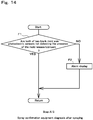
- Fig. 14 is a flow chart showing an example of the spray confirmation equipment diagnosis after spraying (Step A13).
- the spray control portion 31 determines whether or not the any of photoelectric sensors 56A and 57A of the abnormal spray detecting portion 41A are detecting the mold release lubricant L1 (Step F1). For example, if light from the lighting portion to the detecting portion is not blocked by both photoelectric sensors 56A and 57A due to the mold release lubricant L1 discharged from the syringe 52A, the spray control portion 31 determines that the photoelectric sensors 56A and 57A are not detecting the mold release lubricant L1 (YES in Step F1). In other words, the spray control portion 31 determines that the mold release lubricant L1 is sprayed from the syringe 52A of the first mold release lubricant pump L1 as planned.
- Step F1 the spray control portion 31 completes the spray confirmation equipment after spraying (Step A13).
- the spray control portion 31 displays that an abnormality occurs to the mold release lubricant pump 47A on the touch panel 66 (Step F2).
- the spray control portion 31 determines that an abnormality occurs to the mold release lubricant pump 47A.
- Step F1 the photoelectric sensors 56B and 57B conduct a diagnosis of the mold release lubricant pump 47B. Furthermore, the mold release lubricant pump 47B diagnosis using the photoelectric sensors 56B and 57B is the same as the mold release lubricant pump 47A diagnosis using the photoelectric sensors 56A and 57A (Step F1, F2). Thus, a detailed explanation of the mold release lubricant pump 47B diagnosis process using the photoelectric sensors 56B and 57B is omitted.
- the spray control portion 31 causes the syringes 52A and 52B of the mold release lubricant pumps 47A and 47B to intake the mold release lubricants L1 and L2 (Step A14). As a result, the mold release lubricants L1 and L2 for the next mold release lubricant spraying operation are filled in the syringes 52A and 52B.
- the spray control portion 31 determines (Step A15) whether or not the swab cycle transition signal (a signal indicating that the swab cycle is being operated) is received regarding the section 5 where the mold release lubricant spraying operation is conducted immediately before.
- This swab cycle transition signal is output from the glass bottle manufacturing control portion 6 at regular intervals during the swab cycle. When returning to the glass bottle manufacturing cycle, the swab cycle transition signal is cut off.
- Step A15 When the spray control portion 31 receives the swab cycle transition signal, in other words, when the swab cycle is not completed (YES in Step A15), one swab cycle transition signal is added to the receipt counts (Step A16). When the number of received times of the swab cycle transition signal is less than the predetermined threshold value (NO in Step A17), the spray control portion 31 repeats the processing of steps A15 to A17.
- Step A18 when the number of swab cycle transition signals reaches a predetermined number, that is, when the spray control portion 31 receives a signal indicating that the swab cycle is not completed yet for a certain period of time (YES in Step A17), an alarm indicating that the section 5 where the mold release lubricant spraying operation is conducted immediately before, has not been returned to the glass bottle manufacturing cycle, is displayed on the touch panel 66 (Step A18).
- the spray control portion 31 outputs a signal requesting to stop the glass bottle manufacturing operation in the section 5, which is the object of the alarm display in Step A18, to the glass bottle manufacturing control unit 6 (Step A19).
- the spray control portion 31 stops the glass bottle manufacturing operation in the section 5 in which the swab cycle cannot normally shift to the glass bottle manufacturing cycle.
- the spray control portion 31 determines whether or not the swab cycle is completed after causing the spray portions 30A and 30B to perform the mold release lubricant application operation. Then, the spray control portion 31 determines whether or not to perform the abnormality notification (step A18) based on the determination result.
- Step A20 the spray control portion 31 determines whether or not there is a section 5 where the mold release lubricant spraying operation is not conducted yet among the sections 5 designated by the operation display portion 32 (Step A20).
- Step A20 When the mold release lubricant spraying operation is completed for all of the sections 5 designated by the operation display portion 32 (NO in Step A20), one cycle of the mold release lubricant spraying operation is completed. At this time, the spray control portion 31 moves (returns) the spray units 34A and 34B to the first standby positions P1 by driving the transport mechanisms 33A and 33B (step A21). This completes one cycle of the mold release lubricant spraying operation.
- the spray control portion 31 drives the transport mechanisms 33A and 33B.
- the spray control portion 31 starts moving the spraying units 34A and 34B toward the section closest to the section 5 where immediately before the mold release lubricant spraying operation is conducted among the sections 5 where the mold release lubricant spraying operation is not conducted yet although is designated thereto (step A3).
- the two spraying units 34A and 34B are moved together in the arrangement direction A1, and are thus arranged at the same section 5. That is, the two spraying units 34A and 34B are not arranged in the separate sections 5. Then, the processing after step A4 onward is repeated.
- the spraying control portion 31 causes either of the first spray portion 30A or the second spray portion 30B for which the mold release lubricant spraying operation is set on the regular cycle lubricant application setting screen 82, to be processed same as the case (i-1) described above.
- the spray control portion 31 sets either of the first spray portion 30A and the second spray portion 30B, that is, the other spray portion 30 for which the mold release lubricant application operation is not conducted, to standby at the first standby position P1 set outside each section 5 (outside the glass bottle manufacturing portion 3).
- the spray control portion 31 controls the first spray portion 30A and the second spray portion 30B to conduct mutually different operations from each other. Then, the spray control portion 31 does not conduct the aforementioned processing (i-1) on the other spray portion 30.
- the spray control portion 31 may have either of the first spray portion 30A or the second spray portion 30B to apply the mold release lubricant L (case ii-2). In this case, the same processing as the above (i-2) is conducted (when either of the first spray portion 30A or the second spray portion 30B conducts the mold release lubricant spraying operation in the regular cycle lubricant application). However, the spray control portion 31 arranges the first spray portion 30A and the second spray portion 30B at the same section 5.
- the spray control portion 31 causes the spray portions 30 to which the mold release lubricant L is not applied, to stand by at the second standby positions P2 (P2A, P2B) set to the side of the corresponding blank molds 10 or blow molds 18 of the section 5.
- the nozzles 38A sprays the mold release lubricant L1 toward the blank molds 10 as shown in Fig. 15 (A)
- the nozzles 38B is on standby at the second standby position P2B.
- the second spray portion 30B among the spray portions 30A and 30B sprays the mold release lubricant L2 as shown in Fig.
- the spray control portion 31 controls the first spray portion 30A and the second spray portion 30B to conduct mutually different operations from each other.
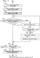
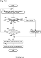
- Fig. 16 is a flow chart showing one example of processing conducted during the monitoring mode for the blank mold 10. Referring to Fig.
- the spray control portion 31 moves the spraying unit 34A from the first standby position P1 to the section 5 conducting the glass bottle manufacturing operation (where the glass bottle manufacturing operation signal is output) closest to the first standby position P1 (Step G1). That is, the abnormality detecting operation is conducted on the section 5 during the glass bottle manufacturing operation.
- the nozzles 38A and 38B are both arranged at the second standby positions P2 (P2A, P2B).
- the spray control portion 31 determines whether or not a lump of glass (gob 101 or parison 102) remains during the timing from when the parison 102 is removed until when the next gob 102 is loaded in the cavity 10c of each blank mold 10 of the sections 5 at which the spraying unit 34A is arranged (Step G2).
- An example of this determination is the same as Step D1 of the residual abnormality detecting operation (Step A10).
- Step G3 When the lump of glass does not remain in the cavity 10c of the blank mold 10 at the above timing (NO in Step G2), the presence / absence of the cancel command is determined (Step G3).
- the cancel commands includes that the start time of the regular cycle lubricant operation comes during the monitoring mode, that the cancel command is issued by operating the touch panel 66 by an operator, or that a time-up occurs.
- the time-up means that a predetermined time elapses since the start of execution of the monitoring mode.
- the time period from the start of execution of the monitoring mode to the time up may be constant or may be set arbitrarily by operating the touch panel 66.
- Step G3 if a cancel command is not issued (NO in Step G3), the spray control portion 31 repeats the processing after Step G1. In addition, in the processing of Step G1 after the second time, the spraying control portion 31 moves the spraying unit 34A to the section 5 in the bottle manufacturing operation and is closest to the section in which the abnormality detecting operation is conducted immediately before.
- Step G3 when it is determined for Step G3 that the cancel command is issued (YES in Step G3), the spray control portion 31 cancels the monitoring mode (Step G4) and returns the spraying unit 34A to the first standby position P1 (Step G5). As a result, the monitoring mode is terminated.
- Step G2 when it is determined in Step G2 that the lump of glass (gob 101 or parison 102) is present in the cavity 10c (YES in Step G2), the spray control portion 31 determines that an abnormality occurs. Then, the spray control portion 31 displays on the touch panel 66 that the lump of glass remains in the blank mold 10 (Step G6).
- Step G6 When the alarm display operation (Step G6) is conducted, the spray control portion 31 outputs a signal to the glass bottle manufacturing control portion 6 requesting glass bottle manufacturing stoppage in the section 5 at which the spraying unit 34A is arranged (Step G7). As a result, the glass bottle manufacturing operation in the section 5 is stopped. Then, the processes of steps G4 and G5 are conducted.
- the spray control portion 31 operates the mold release lubricant application to the blank molds 10 by the first spray portion 30A and the mold release lubricant application to the blow molds 18 by the second spray portion 30B in association with each other.
- This optimizes the application mode of the mold release lubricant L1 on the blank molds 10 and the application mode of the mold release lubricant L2 on the blow molds 18.
- the quality defect in the glass bottle 103 is more reliably suppressed. Further, this prevents running out of the mold release lubricant in the blank molds 10 as well as in the blow molds 18.
- the spray control portion 31 arranges the nozzles 38A and the nozzles 38B at the same section 5 in the regular cycle lubricant application and the temporary lubricant application operation (cases if (i-1) and (ii-1)).
- the nozzles 38A and 38B apply the mold release lubricants L1 and L2 to the blank molds 10 and the blow molds 18 of the same section 5.
- This enables the first spraying section 30A and the second spray section 30B to be arranged so as not to interfere with the forming of the glass bottles with respect to the section 5 that is not the application target of the mold release lubricants L1 and L2.
- the spray control portion 31 controls the first spray portion 30A and the second spray portion 30B to perform different operations from each other in the regular cycle lubricant application and the temporary lubricant application operation (cases of (i-2) and (ii-2)).
- This configuration more optimizes the timing at which the first spray portion 30A applies the mold release lubricant L1 to the blank molds 10, and the timing at which the second spray portion 30B applies the mold release lubricant L2 to the blow molds 18.
- a defect occurs in either of the first spray portion 30A or the second spray portion 30B, it prevents the mold release lubricant L from being sprayed from the defective spray portion 30.
- the spray control portion 31 causes either of the spray portion 30A or 30B to apply the mold release lubricant L in the regular cycle lubricant application, for example, the nozzles 38 to which the mold release lubricant L is not applied, is on standby at the first standby positions P1 set outside the plurality of sections 5.
- This configuration eliminates a wasteful operation of the nozzles 38 to which the mold release lubricant L is not applied.
- the spray control portion 31 when the spray control portion 31 causes either of the spray portion 30A or 30B to conduct the mold release lubricant spraying operation, the spray control portion 31 arranges the nozzles 38A and 38B at the same section 5.
- the nozzles 38 on which the mold release lubricant spraying operation is not conducted may be made to stand by at the second standby positions P2 set to the side of the blank molds 10 or the blow molds 18.
- the nozzles 38 that does not conduct the mold release lubricant spraying operation may be made to stand by at a position close to the corresponding blank molds 10 or blow molds 18 in the section 5 where the mold release lubricant L is applied. This shortens the time from the receiving the mold release lubricant spraying operation command to the starting the mold release lubricant spray operation for the nozzles 38 in which the mold release lubricant spraying operation is not conducted.
- At least one (both in the present embodiment) of the first spray portion 30A and the second spray portion 30B includes the glass residual detecting portions 42A and 42B, and the spray control portion 31 may detect abnormalities with the glass residual detecting portions 42A and 42B on a plurality of sections 5.
- This configuration may detect an abnormality in the plurality of sections 5 in the glass bottle manufacturing portion 3 including the blank molds 10 and the blow molds 18 with the spray portions 30.
- the spray unit 34 can be used not only for spraying the mold release lubricant but also for detecting an abnormality in the glass bottle manufacturing portion 3.
- the spray control portion 31 notifies the glass bottle manufacturing control portion 6 of the abnormality and causes the section 5 in which the lump of glass is detected to stop the glass bottle manufacturing operation.
- the glass residual detecting portion 42 detects the abnormality in the glass bottle manufacturing portion 3 including the blank molds 10 and the blow molds 18, which causes the malfunction of the spray portions 30. Accordingly, this configuration prevents the nozzles 38 of the corresponding spray portions 30 from entering toward the blank mold 10 or the blow mold 18 in which the lump of glass remains.
- the spray control portion 31 causes at least either of the spray portion 30A or 30B to conduct the mold release lubricant application operation during the swab cycle among the glass bottle manufacturing cycle and the swab cycle.
- the mold release lubricant application operation by the spray portions 30 can be conducted in the swab cycle in which the glass bottle molding by the blank molds 10 and the blow molds 18 is not conducted temporarily during the operation of the glass bottle manufacturing unit 3. Therefore, the dedicated time for applying the mold release lubricant L can be reduced.
- the abnormal spray detecting portion 41 detects the mold release lubricant spray abnormality from the spray portions 30, so that the spray abnormality regarding the mold release lubricant L having high viscosity can be detected more accurately.
- a mold release lubricant application equipment for glass bottle forming molds comprising:
- the mold release lubricant application equipment for the glass bottle forming molds comprising:
- a mold release lubricant application equipment for glass bottle forming molds comprising:
- the mold release lubricant application equipment for the glass bottle forming molds according to any of supplementary notes 1 to 3, wherein the molds are provided as blank molds, and the application portion is provided as a first application portion for applying the mold release lubricant to the blank molds.
- the mold release lubricant application equipment for the glass bottle forming molds according to any of supplementary notes 1 to 4, wherein the molds are provided as blow molds, and the application portion is provided as a second application portion for applying the mold release lubricant to the blow molds.
- the mold release lubricant application equipment for the glass bottle forming molds according to any of supplementary notes 1 to 5, wherein the molds are provided as blank molds and blow molds, the application portions are provided as a first application portion for applying the mold release lubricant to the blank molds and a second application portion for applying the mold release lubricant to the blow molds, and the application control portion operates the first application portion and the second application portion in association with each other.
- the mold release lubricant application equipment for the glass bottle forming molds wherein the plurality of the blank molds are arranged independently along a predetermined arrangement direction, the plurality of the blow molds are arranged independently along the predetermined arrangement direction, the first application portion comprises a first lubricant application part for applying the mold release lubricant, and a first transport mechanism for moving the first lubricant application part among the plurality of the blank molds along the arrangement direction, the second application portion comprises a second lubricant application part for applying the mold release lubricant, and a second transport mechanism for moving the second lubricant application part among the plurality of the blow molds along the arrangement direction, and the application control portion operates the first transport mechanism and the second transport mechanism in association with each other.
- the mold release lubricant application equipment for the glass bottle forming molds according to supplementary note 7, wherein a plurality of sections comprising the blank molds and the blow molds are formed along the arrangement direction, and the application control portion operates the first application portion and the second application portion to apply the mold release lubricant to at least one of the sections.
- the mold release lubricant application equipment for the glass bottle forming molds according to supplementary note 8, wherein the application control portion controls the first lubricant application portion and the second lubricant application portion so that the first lubricant application part and the second lubricant application part are positioned at the same section.
- the mold release lubricant application equipment for the glass bottle forming molds according to either of supplementary note 8 or 9, wherein the application control portion controls the first application portion and the second application portion to conduct mutually different operations from each other.
- the mold release lubricant application equipment for the glass bottle forming molds according to supplementary note 10, wherein when the application control portion causes either of the first lubricant application part or the second lubricant application part to conduct a mold release lubricant application operation, the lubricant application part that is not applying the mold release lubricant is standby at a predetermined first standby position which is set outside the plurality of sections.
- the mold release lubricant application equipment for the glass bottle forming molds according to either of supplementary note 10 or 11, wherein when the application control portion causes either of the first lubricant application part or the second lubricant application part to conduct the mold release lubricant application operation, the first lubricant application part and the second lubricant application part are arranged at the same section, and the lubricant application part that is not applying the mold release lubricant, is standby at a predetermined second standby position which is set to the side of corresponding blank molds or blow molds at the section.
- the mold release lubricant application equipment for the glass bottle forming molds according to any of supplementary notes 6 to 12; wherein a glass bottle manufacturing cycle for forming glass bottles and a swab cycle, in which the gob is not charged into the blank mold, are provided in a glass bottle manufacturing portion comprising the blank molds and the blow molds; and the application control portion causes at least either of the first application portion or the second application portion to apply the mold release lubricant during the swab cycle.
- a mold release lubricant application equipment for glass bottle forming molds comprising:
- the mold release lubricant application equipment for the glass bottle forming molds according to supplementary note 14, wherein the application control portion is configured so as to select either of an application operation, wherein both the first application portion and the second application portion apply the mold release lubricant, or wherein either of the first application portion or the second application portion applies the mold release lubricant.
- This invention may be applied as a mold release lubricant application equipment for the glass bottle forming molds.
Landscapes
- Chemical & Material Sciences (AREA)
- Engineering & Computer Science (AREA)
- Materials Engineering (AREA)
- Organic Chemistry (AREA)
- Manufacturing & Machinery (AREA)
- Mechanical Engineering (AREA)
- Re-Forming, After-Treatment, Cutting And Transporting Of Glass Products (AREA)
- Spray Control Apparatus (AREA)
- Moulds For Moulding Plastics Or The Like (AREA)
Abstract
Description
- This invention relates to a mold release lubricant application equipment for glass bottle blow forming molds.
- Equipment for spraying a mold release lubricant on blank molds of the glass bottle forming molds is known technology (refer to
Patent Literature 1, 2). -
- [Patent Literature 1]
JP 5118131 - [Patent Literature 2]
JP 6277308 - A glass bottle forming mold comprises a blank mold and a blow mold. Furthermore, the blank mold forms a gob (a lump of molten glass) into a parison and the blow mold forms the parison into a glass bottle.
- There is a need to apply the mold release lubricant to a blank mold cavity (forming surface) and a blow mold cavity (forming surface) in order to ensure slipperiness and releasability for the glass being formed. However,
Patent Literature - This invention aims to provide an application equipment for applying the mold release lubricant to the glass bottle forming molds.
- One aspect of this invention relates to a mold release lubricant application equipment for glass bottle forming molds, comprising:
- application portions for applying the mold release lubricant to the glass bottle forming molds, and an application control portion that operates the application portions; wherein
- the molds are arranged independently along a predetermined arrangement direction;
- a plurality of sections comprising the molds are formed along the arrangement direction;
- the application portions comprise lubricant application parts for applying the mold release lubricant to the molds, transport mechanisms for moving the lubricant application parts among the plurality of the sections along the arrangement direction, and sensors; and
- the application control portion detects abnormalities in the plurality of sections using the sensors.
- Another aspect of this invention relates to a mold release lubricant application equipment for glass bottle forming molds, comprising:
- an application portions for applying a mold release lubricant to the glass bottle forming molds, and an application control portion that operates the application portions; wherein
- the application portions are structured to spray the mold release lubricant onto the molds,
- the application portions comprise abnormal spray detecting portions to check for any spray abnormality of the mold release lubricant in the application portion, and
- the application control portion notifies an abnormality, when the abnormal spray detecting portion detects the spray abnormality.
- Another aspect of this invention relates to a mold release lubricant application equipment for glass bottle forming molds, comprising:
- a first application portion for applying a mold release lubricant to blank molds for glass bottle forming,
- a second application portion for applying the mold release lubricant to blow molds for the glass bottle forming, and
- an application control portion that operates the first application portion and the second application portion in association with each other; wherein
- the plurality of the blank molds are arranged independently along a predetermined arrangement direction;
- the plurality of the blow molds are arranged independently along the arrangement direction;
- the first application portion comprises a first lubricant application part for applying the mold release lubricant, and a first transport mechanism for moving the first lubricant application part among the plurality of the blank molds along the arrangement direction;
- the second application portion comprises a second lubricant application part for applying the mold release lubricant, and a second transport mechanism for moving the second lubricant application part among the plurality of the blow molds along the arrangement direction;
- a plurality of sections comprising the blank molds and the blow molds are formed along the arrangement direction; and
- the application control portion is configured so as to execute an application operation, wherein both the first application portion and the second application portion apply the mold release lubricant, and wherein either of the first application portion or the second application portion applies the mold release lubricant.
-
- [
Fig. 1] Fig. 1 is a schematic plain view of a glass bottle manufacturing equipment according to one embodiment of the present invention showing a simplified view with partial omission. - [
Fig. 2] Fig. 2 is a schematic side view of the glass bottle manufacturing equipment used to manufacture glass bottles showing a partial cross-section view with partial omission. - [
Fig. 3] Fig. 3 is a schematic side view exemplifying a part of the glass bottle manufacturing equipment with the mold release lubricant sprayed, and shows a partial cross-section view with partial omission. - [
Fig. 4] Fig. 4 is a schematic side view of the first spray portion in a mold release lubricant spraying equipment of the glass bottle manufacturing equipment. - [
Fig. 5] Fig. 5 is a schematic side view of the second spray portion in the mold release lubricant spraying equipment of the glass bottle manufacturing equipment. - [
Fig. 6] Fig. 6 is a schematic side view of part of a mold release lubricant pump of the first spray portion and the mold release lubricant pump of the second spray portion showing a partial cross-section view. - [
Fig. 7] Fig. 7 is a block diagram schematically showing a major part of an electrical structure of the glass bottle manufacturing equipment. - [
Fig. 8] Fig. 8 illustrates a regular cycle lubricant application setting screen. - [
Fig. 9] Fig. 9 illustrates a lubricant application history screen. - [
Fig. 10] Fig. 10 is a flow chart explaining one example of the mold release lubricant spraying operation conducted by both (i-1) the first spray portion and the second spray portion as part of the (i) regular cycle lubricant application operation. - [
Fig. 11 ] Similar toFig. 10 ,Fig. 11 is a flow chart explaining one example of the mold release lubricant spraying operations conducted by both (i-1) the first spray portion and the second spray portion as part of the (i) regular cycle lubricant application operation. - [
Fig. 12] Fig. 12 is a flow chart showing one example of a diagnosis (Step A5) conducted by a spray confirmation equipment before spraying. - [
Fig. 13] Fig. 13 is a flow chart explaining one example of processes conducted by a glass residual detecting operation. - [
Fig. 14] Fig. 14 is a flow chart showing one example of a diagnosis (Step A13) conducted by the spray confirmation equipment after spraying. - [
Fig. 15] Fig. 15 (A) is a schematic diagram showing one example of operations when only the first spray portion of a system that consists of the first spray portion and the second spray portion conducts mold release lubricant spraying operation during (ii) temporary lubricant application.Fig. 15 (B) is a schematic diagram showing one example of operations when only the second spray portion of a system that consists of the first spray portion and the second spray portion conducts the mold release lubricant spraying operation during (ii) temporary lubricant application. - [
Fig. 16] Fig. 16 is a flow chart showing one example of operations conducted by an abnormality detecting operation during a monitoring mode for a blank mold. - A description of the embodiment of the present invention is provided below referring to the figures.
-
Fig. 1 is a schematic plain view of glassbottle manufacturing equipment 1 according to one embodiment of the present invention showing a simplified view with partial omission.Fig. 2 is a schematic side view of the glassbottle manufacturing equipment 1 whilemanufacturing glass bottles 103, with partial omission.Fig. 3 is a schematic side view exemplifying a part of the glassbottle manufacturing equipment 1 with the mold release lubricant sprayed, with a partial cross-sectional view and partial omission. -
Fig. 4 is a schematic side view of thefirst spray portion 30A of a mold releaselubricant spraying equipment 4 of the glassbottle manufacturing equipment 1.Fig. 5 is a schematic side view of thesecond spray portion 30B of the mold releaselubricant spraying equipment 4 of the glassbottle manufacturing equipment 1.Fig. 6 is a schematic side view of a moldrelease lubricant pump 47A of thefirst spray portion 30A and of a moldrelease lubricant pump 47B of thesecond spray portion 30B, with partial cross-sectional view. - Referring to
Figs. 1 to 3 , the glass bottle manufacturing equipment 1 (hereinafter, simply referred to as manufacturing equipment 1) uses ablank mold portion 7 to form gob 101 (a lump of molten glass) supplied by a gob supply mechanism (not shown) into aparison 102. Furthermore, ablow mold portion 9 is used to form theparison 102 into theglass bottle 103. As shown in this embodiment, theglass bottle 103 may be formed using the blow and blow process, or may be formed via the press and blow process. Furthermore, in this embodiment, themanufacturing equipment 1 can form twogobs 101 simultaneously into theglass bottles 103 via eachsingle section 5. Note that themanufacturing equipment 1 is not limited to form two bottles simultaneously in asingle section 5. The embodiment may comprise a structure that can simultaneously formglass bottles 103 from one or three ormore gobs 101. - The
manufacturing equipment 1 comprises a gob supply mechanism (not shown), a glassbottle manufacturing portion 3, the mold releaselubricant spraying equipment 4 to serve as the mold release lubricant application equipment, and a glass bottlemanufacturing control portion 6 to control the glassbottle manufacturing portion 3. - A plurality of
sections 5 are formed in the glassbottle manufacturing portion 3. - For example, 8-12
sections 5 are provided to the glassbottle manufacturing portion 3, which are arranged at substantially even intervals along a predetermined arrangement direction A1. - Each
section 5 comprises theblank mold portion 7, aneck ring portion 8, and theblow mold portion 9. - The
blank mold portion 7 works in correlation with theneck ring portion 8 to form thegob 101 supplied from the gob supply mechanism to form theparison 102. - The
blank mold portion 7 comprises twoblank molds 10 for glass bottle forming, and blank mold open/close mechanism 11. - Each
blank mold 10 comprises a pair ofsplit molds split molds cavity 10c in which thegob 101 is formed into aparison 102. The opening and closing operation of the pair ofsplit molds blank mold 10 is controlled by the blank mold open/close mechanism 11. Mold release lubricant L1 is regularly applied to the inner surface of thecavity 10c via thefirst spray portion 30A of the mold releaselubricant spraying equipment 4. The mold release lubricant L1 is used to maintain slipperiness between the gob 101 and the blank mold inner surface as well as the releasability of theparison 102 from theblank mold 10. - When the
gob 101 is formed into theparison 102, aneck ring 12 of theneck ring portion 8 is positioned below theblank mold 10. Theneck ring portion 8 is provided to form afinish area 103a from thegob 101. Furthermore, theneck ring portion 8 is structured so as to transfer theparison 102 formed via theblank mold 10 to theblow mold portion 9. - The
neck ring portion 8 comprises two neck rings 12, aneck ring holder 13 to support the neck rings 12, arotary shaft 14 to which theneck ring holder 13 is attached, and a neck ring open/close mechanism 15. - Each
neck ring 12 comprises a pair of half cylindrical shapedsplit molds split molds neck ring 12. Via a movement of the neck ring open/close mechanism 15, splitmolds gob 101 into theparison 102, a part of theneck ring 12 fits a bottom of theblank mold 10. - In this embodiment, the
neck ring holder 13 is an L-shaped arm member. A mounting position of theneck ring holder 13 is attached to therotary shaft 14 that extends horizontally. Usingrotary mechanism 16, theneck ring holder 13 and the neck rings 12 are able to rotate around the central axis of therotary shaft 14. With this rotation, the neck rings 12 travel between a position at the bottom of the blank mold 10 (position inFig. 1 ) and a position at the top of the blow mold portion 9 (position inFig. 3 ). - The
blow mold portion 9 comprises twoblow molds 18 for forming glass bottles, twobottom molds 19, and a blow mold open/close mechanism 20. - Each
blow mold 18 forms theglass bottle 103 by working together with the correspondingbottom mold 19 to form the portion of theparison 102 that does not contain thefinish area 103a. Eachblow mold 18 comprises a pair ofsplit molds close mechanism 20 opens and closes the pair of 18a and 18b of theblow mold 18. These splitmolds blow mold 18. - The inner surface of the
blow mold 18 and upper surface of thebottom mold 19 form acavity 18c in which a part of theparison 102 other than thefinish area 103a are inserted. The upper surface of each splitmold blow mold 18 is flat surface and structured so as to receive thefinish area 103a of theglass bottle 103. The upper area of the inner surface of thecavity 18c of theblow mold 18 includes aneck forming area 18d for forming a neck area of theglass bottle 103. The center area of the inner surface of thecavity 18c of theblow mold portion 9 contains ashoulder forming area 18e for forming a shoulder area of theglass bottle 103. Furthermore, the upper surface of thebottom mold 19 comprises abottom forming area 19a for forming the bottom of theglass bottle 103. A coating layer is formed, such as coated with carbon, on the inner surface of theblow mold 18 and the upper surface of thebottom mold 19. Furthermore, mold release lubricant L2 is regularly applied to these inner surfaces with thesecond spray portion 30B of the mold releaselubricant spraying equipment 4. The mold release lubricant L2 is applied to ensure ease of releasability of theglass bottle 103 from theblow mold 18 and thebottom mold 19. - In the
aforementioned blow mold 18, theparison 102 is formed into theglass bottle 103 by compressed air for forming being supplied from a blow head (not shown) towards theparison 102, the majority of which is placed in thecavity 18c. From there, theglass bottle 103 is taken out from theblow mold 18 with a takeout arm (not shown), subsequently is transferred by a conveyor (not shown). - A plurality of
sections 5 are formed along the arrangement direction A1. Eachsection 5 includes theblank molds 10, the neck rings 12, and theblow molds 18, which are aligned in the direction perpendicular to the arrangement direction A1 in plain view. Via this structure, a plurality ofblank molds 10 are arranged independently along the arrangement direction A1. Furthermore, a plurality ofblow molds 18 are arranged independently along the arrangement direction A1. -
Fig. 7 is a block diagram showing a schematic view of the major part of the electric structure of themanufacturing equipment 1. Referring toFigs. 1 to 7 , the glassbottle manufacturing portion 3 comprising the aforementioned structure is controlled by the glass bottlemanufacturing control portion 6. The glass bottlemanufacturing control portion 6 comprises a computer containing, for example, a CPU (Central Processing Unit), ROM (Read Only Memory), and RAM (Random Access Memory), and a PLC (Programmable Logic Controller) or a sequence circuit and the like. - The glass bottle
manufacturing control portion 6 is electrically connected to the gob supply mechanism, and outputs commands to the gob supply mechanism to supply thegobs 101 from the gob supply mechanism to theblank molds 10 and commands to stop supplying thegobs 101 from the gob supply mechanism to theblank molds 10. - The glass bottle
manufacturing control portion 6 is electrically connected to the blank mold open/close mechanism 11, the neck ring open/close mechanism 15, and the blow mold open/close mechanism 20, and controls the open/close operations for thesemechanisms - Furthermore, the glass bottle
manufacturing control portion 6 is electrically connected to therotary mechanism 16 that rotationally drives therotary shaft 14, and controls the position of the neck rings 12 by controlling therotary mechanism 16. - The mold release lubricant L1 used to ensure slipperiness and releasability (easiness of removal) between the
blank mold 10 and theparison 102, is applied during forming process of theglass bottle 103. The mold release lubricant L2 used to ensure slipperiness and releasability (easiness of removal) between theblow mold 18 andglass bottle 103 is applied during forming process of theglass bottle 103. The mold releaselubricant spraying equipment 4 is used to apply these mold release lubricants L1 and L2. Hereinafter, the mold releaselubricant spraying equipment 4 is simply referred to as aspraying equipment 4. - The
spraying equipment 4 comprises the first spray portion (the first application portion) 30A for applying the mold release lubricant L1 for theblank molds 10, to the inner surfaces of thecavities 10c of theblank molds 10, the second spray portion (the second application portion) 30B for applying the mold release lubricant L2 used for the neck rings 12, theblow molds 18, and thebottom molds 19, to the inner surfaces ofcavities 12c of the neck rings 12, the upper surfaces of theblow molds 18, and the inner surfaces of thecavities 18c, a spray control portion (the application control portion) 31 for operating thefirst spray portion 30A and thesecond spray portion 30B in association with each other, and anoperation display portion 32. - This embodiment is explained using an example of a structure through which the
second spray portion 30B applies the mold release lubricant L2 to the inner surfaces of thecavities 12 of the neck rings 12 but this is not a required structure. For example, this embodiment may be structured so that thefirst spray portion 30A applies the mold release lubricant L1 to the inner surfaces of thecavities 12c of the neck rings 12. - This embodiment is explained using an example of an embodiment through which the mold release lubricant L1 and the mold release lubricant L2 are sprayed via
nozzles 38A andnozzles 38B respectively as the lubricant application parts though, this is not a required embodiment. For example, this embodiment may be structured so that the mold release lubricant L1 and the mold release lubricant L2 are applied using the lubricant application parts such as a brush in place of thenozzles 38A and thenozzles 38B. - In this embodiment, the structural parameters of the
first spray portion 30A are described with a letter "A" in addition to a numerical code and the structural parameters of thesecond spray portion 30B are described with a letter "B" in addition to a numerical code. Furthermore, the same numerical code is applied to the structural parameters of thefirst spray portion 30A and the structural parameters of thesecond spray portion 30B. When collectively referring to the structural parameters of thefirst spray portion 30A and the structural parameters of thesecond spray portion 30B, the codes "A" and "B" may be omitted with only the numerical codes indicated. - In this embodiment, when the arrangement direction A1 is aligned, the
first spray portion 30A and thesecond spray portion 30B are structured as shown in the plain view shown inFig. 1 (symmetrical to the direction perpendicular to the arrangement direction A1). Furthermore, excluding the point that thefirst spray portion 30A sprays the mold release lubricant L1 to theblank molds 10, and thesecond spray portion 30B sprays the mold release lubricant L2 to theblow molds 18, these structures are identical. Thus, the explanation below mostly refers to as the structure of thefirst spray portion 30A and omits the explanation of thesecond spray portion 30B. - Referring to
Figs. 1 ,3 , and4 , thefirst spray portion 30A is provided on a plurality ofsections 5 in relation to theblank mold portion 7. In other words, the singlefirst spray portion 30A sprays the mold release lubricant L1 to all theblank mold portions 7. - As the mold release lubricant L1 applied by the
first spray portion 30A, a mineral oil containing graphite particles as a solid lubricant may be exemplified. In this embodiment, thefirst spray portion 30A is structured so as to apply the mold release lubricant L1 to, at least a part of the upper and lower surfaces inside thecavity 10c of theblank mold 10. - The
first spray portion 30A comprises a transport mechanism 33 (the first transport mechanism) A and aspraying unit 34A. - The
transport mechanism 33A is provided to move thespraying unit 34A that includes thenozzles 38A for applying the mold release lubricant L1, among a plurality ofblank molds 10 along the arrangement direction A1. Thetransport mechanism 33A is able to position thenozzles 38A of thespraying unit 34A in the side of theblank mold portion 7 in thesection 5 where the mold release lubricant L1 is sprayed. - The
transport mechanism 33A comprises arail 35A, which extends along the arrangement direction A1,base parts 36A that move on therail 35A, and atransport motor 37A that serves as a drive motor for transmitting a driving force to thebase parts 36A in the arrangement direction A1. Thebase parts 36A are provided with thespraying unit 34A. - The
spraying unit 34A is structured so as to spray the mold release lubricant L1 on eachsection 5 by moving along the arrangement direction A1. Furthermore, in this embodiment, thespraying unit 34A has a monitoring function whether or not an abnormality is occurring in theblank mold portion 7. When not working, thespraying unit 34A is positioned at a designated first standby position P1. In this embodiment, the first standby position P1 is further set outside from the one end of plurality of thesections 5 along the arrangement direction A1. At the first standby position P1, thespraying unit 34A does not face any ofsections 5 in a direction that is perpendicular to the arrangement direction A1. - The
spraying unit 34A comprises the nozzles (the first lubricant application parts) 38A that sprays the mold release lubricant L1, amanipulator 39A for changing the position of thenozzles 38A, a mold releaselubricant supply portion 40A for supplying the mold release lubricant L1 to thenozzles 38A, an abnormalspray detecting portion 41A, and a glass residual detectingportion 42A. - The
nozzles 38A are used to spray the mold release lubricant L1. In this embodiment, thenozzles 38A are formed in a shape of thin, long rods. Note that thenozzles 38A are does not necessarily to be a thin, long rod shape. The number ofnozzles 38A provided is the same as the number ofblank molds 10 in asingle section 5. In this embodiment, two are provided. Eachnozzle 38A is formed to have a length that at least enables the tip of thenozzle 38A to be inserted into thecavity 10c. Eachnozzle 38A may spray theblank mold 10 with the mold release lubricant L1 while being raised by themanipulator 39A, or being lowered, or may spray the mold release lubricant L1 after being inserted in thecavity 10c in a stop state. Spray holes 43A are formed on the tip ofnozzle 38A. A diameter of the spray holes 43A are structured, for example, to be approximately 1mm or smaller. The mold release lubricant L1 is sprayed from the spray holes 43A to form, for example, a full cone spray pattern. - The mounting part of the
nozzle 38A is fixed onto the hollow shaft shaped manifold 45A. A channel for the mold release lubricant L1 is formed inside the manifold 45A. The mold release lubricant L1 passes through the manifold 45A into the channel of thecorresponding nozzle 38A and is sprayed from the correspondingspray holes 43A. - The
manipulator 39A is used to change the position ofnozzles 38A with respect to theblank molds 10 as well as to maintain the position of thenozzles 38A. Themanipulator 39A is formed, for example, using a multiple joint robot with multiple axes. Themanipulator 39A, in this embodiment, can cause thenozzles 38A to rotate around each joint, and to shift parallel to direction of X, Y, and Z axes that are mutually orthogonal. - Note that it is acceptable if the
manipulator 39A can at least cause thenozzles 38A to enter and exit thecavities 10c of theblank molds 10, thus there are no limitations on a specific structure. The manifold 45A is fixed to the tip of themanipulator 39A. As a result, themanipulator 39A and the manifold 45A can change the position of thenozzles 38A. - The mold release
lubricant supply portion 40A is provided to supply the mold release lubricant L1 to thenozzles 38A via themanifold 45A. - The mold release
lubricant supply portion 40A comprises a moldrelease lubricant tank 46A and the moldrelease lubricant pump 47A. - Compressed air is supplied to a mold
release lubricant regulator 54A (to be described later) of the moldrelease lubricant pump 47A and anair regulator 53A, from an air compressor or other compressed air supply source (not shown) installed at a distance from the mold releaselubricant supply portion 40A. The moldrelease lubricant regulator 54A is connected to the moldrelease lubricant tank 46A. The moldrelease lubricant tank 46A is a tank for filling the mold release lubricant L1. The air pressure from a compressed air supply source is applied to the mold release lubricant L1 contained in the moldrelease lubricant tank 46A. - The mold
release lubricant pump 47A is provided to supply the mold release lubricant L1 to thenozzles 38A at a predetermined pressure. In this embodiment, the moldrelease lubricant pump 47A is a volumetric pump, which is a kind of reciprocating pump. The moldrelease lubricant pump 47A draws in and discharges the mold release lubricant L1 by using supplied compressed air as a dynamic fluid. - The mold
release lubricant pump 47A comprises acheck valve 49A, a three-way coupling joint 50A, an on/offvalve 51A, asyringe 52A, theair regulator 53A, and the moldrelease lubricant regulator 54A. - The
check valve 49A is connected to the moldrelease lubricant tank 46A and the three-way coupling joint 50A. Thecheck valve 49A allows movement of the mold release lubricant L1 from the moldrelease lubricant tank 46A to the three-way coupling joint 50A but prevents reverse flow of the mold release lubricant L1 from the three-way coupling joint 50A to the moldrelease lubricant tank 46A. - The three-way coupling joint 50A is a pipe connecting the
check valve 49A (the moldrelease lubricant tank 46A), thesyringe 52A, and thenozzles 38A (hose 55A). - The on/off
valve 51A, for example, is a needle valve and thespray control portion 31, which controls on and off of pilot air supply to the needle valve, controls the on/off operation of the on/offvalve 51A. The on/offvalve 51A is connected to the manifold 45A via, for example, a flexible hose 55A. The mold release lubricant L1 passing through the on/offvalve 51A passes through the hose 55A and the manifold 45A to reach thenozzles 38A and is sprayed from thespray holes 43A of thenozzles 38A. - The
syringe 52A alternatively suctions or discharges the mold release lubricant L1 by compressed air. Thesyringe 52A is a material that is formed into a thin, long cylindrical shape, in which compressed air is introduced via theair regulator 53A, and the mold release lubricant L1 is introduced via the moldrelease lubricant regulator 54A and the moldrelease lubricant tank 46A. The abnormalspray detecting portion 41A, for example, optically monitors thesyringe 52A for a state of the mold release lubricant L1. Thus, in this embodiment, thesyringe 52A is made from a material with translucency. With this structure, changes in the amount of the mold release lubricant L1 in thesyringe 52A, in other words, changes in discharge of the mold release lubricant L1 from a single mold release lubricant spraying operation by the moldrelease lubricant pump 47A are monitored. - The upper end of the
syringe 52A is connected to theair regulator 53A. The compressed air enters and exits thesyringe 52A through the upper end. The lower end of thesyringe 52A is connected to the moldrelease lubricant tank 46A via the three-way coupling joint 50A. The mold release lubricant L1 enters and exits thesyringe 52A through this lower end. - Referring to
Figs. 4 and6 , the first upper limit P11A of the mold release lubricant L1 inside thesyringe 52A is the highest fluid level (upper surface) when the mold release lubricant L1 is taken into thesyringe 52A. - The first lower limit P14A of the mold release lubricant L1 in the
syringe 52A is the fluid level at the time of completion of discharge of the mold release lubricant L1 from thesyringe 52A to thenozzles 38A. This is the lowest surface level of the mold release lubricant L1 inside thesyringe 52A. When the moldrelease lubricant pump 47A is not experiencing an abnormality, the first lower limit P14A is the level at which the mold release lubricant L1 is constantly present. - The
air regulator 53A is provided to adjust the pressure of compressed air supplied into thesyringe 52A from the compressed air supply source. Theair regulator 53A is an electro pneumatic regulator and is controlled by thespray control portion 31. - More specifically, the
spray control portion 31 controls theair regulator 53A to control the supply of compressed air to thesyringe 52A and discharge of compressed air from thesyringe 52A. Furthermore, thespray control portion 31 controls the on/off operation of the on/offvalve 51A. Through this implementation, thespray control portion 31 controls supply of the mold release lubricant L1 from the moldrelease lubricant pump 47A to thenozzles 38A. - Subsequently, the intake operation of the mold release lubricant L1 with the mold
release lubricant pump 47A is described. - When the mold release lubricant L1 is taken into the
syringe 52A of the moldrelease lubricant pump 47A, thespray control portion 31 closes the on/offvalve 51A and controls theair regulator 53A to keep the air pressure inside thesyringe 52A lower than the liquid pressure of the mold release lubricant inside thesyringe 52A. As a result, the mold release lubricant L1 passes through thecheck valve 49A and the three-way coupling joint 50A to flow into thesyringe 52A. After the mold release lubricant L1 reaches the first upper limit P11A, thespray control portion 31 controls theair regulator 53A to keep the air pressure inside thesyringe 52A higher than the liquid pressure inside thesyringe 52A. As a result, thecheck valve 49A closes to stop the flow of the mold release lubricant L1 to thesyringe 52A. - Subsequently, the discharge operation (spraying) of the mold release lubricant L1 with the mold
release lubricant pump 47A is described. - When spraying the mold release lubricant L1, the
spray control portion 31 opens the on/offvalve 51A. As a result, compressed air, whose pressure is adjusted by theair regulator 53A, pushes out the mold release lubricant L1 in thesyringe 52A to be sprayed through the spray holes 43A. After spraying for a predetermined time period, thespray control portion 31 closes the on/offvalve 51A. This completes the spraying of the mold release lubricant L1 from the moldrelease lubricant pump 47A. - The mold
release lubricant pump 47A conducts the mold release lubricant L1 spraying operation as a single cycle of the abovementioned intake operation and discharge operation of the mold release lubricant. - The abnormal
spray detecting portion 41A is provided to detect any abnormality in thefirst spray portion 30A. - The abnormal
spray detecting portion 41A is structured so as to detect the mold release lubricant L1 to check for any abnormality in spraying the mold release lubricant L1 in thefirst spray portion 30A. - The abnormal
spray detecting portion 41A comprises firstphotoelectric sensors photoelectric sensor syringe 52A. Each firstphotoelectric sensor photoelectric sensor spray control portion 31. It is acceptable if eachphotoelectric sensor - The first
photoelectric sensor 56A is positioned near the first upper limit P11A and near the first upper detecting position P12A below the first upper limit P11A, and outputs different detection signals depending on when the mold release lubricant L1 is present at the first upper detecting position P12A, or not. The firstphotoelectric sensor 57A is positioned near the first lower limit P14A and near the first lower detecting position P13A above the first lower limit P14A, and outputs different detection signals depending on when the mold release lubricant L1 is present at the first lower detecting position P13A, or not. - In this way, the first upper detecting position P12A and the first lower detecting position P13A are arranged between the first upper limit P11A and the first lower limit P14A in the longitudinal direction of the
syringe 52A. This is a measure against a concave meniscus to be formed on the mold release lubricant L1 liquid surface level via an interaction between the mold release lubricant L1 and thesyringe 52A. This arrangement eliminates the impact of the meniscus caused by the interaction between the mold release lubricant L1 and thesyringe 52A. The firstphotoelectric sensors syringe 52A that is comprised of a light-transmitting portion. - Note that in this embodiment, despite of the description of the structure for detecting the mold release lubricant L1 using the first
photoelectric sensors photoelectric sensors - An exemplification of an abnormality that could occur in the
spraying unit 34A is the sprayed amount of the mold release lubricant L1 from thespray holes 43A of thenozzle 38A, which diverges from a design value. The abnormality can be exemplified as (1) malfunctions in the compressed air supply source or the on/offvalve 51A, theregulators check valve 49A, spray pressure changes due to cracks in release lubricant L1 piping or compressed air piping, (2) changes in spray time due to the on/offvalve 51A operating errors, (3) changes in mold release lubricant temperature (viscosity) due to air temperature change, and (4) changes of the spray area of the mold release lubricant L1 due to clogs in thespray holes 43A of thenozzle 38A. - Furthermore, abnormalities occurring in the
first spray portion 30A are detected by the abnormalspray detecting portion 41A. Specifically, if an abnormality in mold release lubricant discharge occurs to the syringe 52 of the moldrelease lubricant pump 47A, after the mold release lubricant L1 discharge operation starts by the moldrelease lubricant pump 47A, it is perceivable that the first mold release lubricant L1 liquid surface does not reach the first lower detecting position P13A within a predetermined time. Furthermore, in the event of an abnormality of intake of the mold release lubricant occurs to thesyringe 52A of the moldrelease lubricant pump 47A, after the start of the mold release lubricant L1 intake operation by the moldrelease lubricant pump 47A, it is perceivable that the first mold release lubricant L1 liquid surface does not reach the first upper detecting position P12A within the predetermined time. Furthermore, after the intake operation, it is perceivable that the mold release lubricant L1 liquid surface is to fall below the first upper detecting position P12A before the on/offvalve 51A opens (prior to discharge start). As a result, in this embodiment, thespray control portion 31 detects these types of abnormalities based on the presence of the mold release lubricant L1 detected by the firstphotoelectric sensors - The
spraying unit 34A has a structure for detecting the spray abnormality of the mold release lubricant described above as well as a structure for detecting abnormal residual glass lumps occurring to theblank mold 10. Specifically, thespraying unit 34A comprises the glass residual detectingportion 42A. - Referring to
Figs. 1 ,2 , and4 , the glass residual detectingportion 42A is provided to detect whether or not a gob 101 orparison 102 remains in the form of a lump of glass inside thecavity 10c of eachblank mold 10. The glass residual detectingportion 42A is one example of "a sensor" in this invention. The glass residual detectingportion 42A is, for example, formed using a CCD camera (Charge Couple Device Camera) or other solid body imaging element for photographing thecavity 10c, and photographs the inner surface of eachcavity 10c in thesection 5 at which thespraying unit 34A is arranged. Note that it is acceptable as long as the glass residual detectingportion 42A detects a lump of glass in a molten state or at a high temperature close to a molten state, the sensor may be an infrared detection device and the like. - Subsequently, referring to
Figs. 1 to 6 , a structure of thesecond spray portion 30B is described. Note that, as described previously, the structure of thesecond spray portion 30B is the same as thefirst spray portion 30A, thus the explanation of thesecond spray portion 30B has been simplified. - As the mold release lubricant L2 applied by the
second spray portion 30B, a mineral oil containing graphite particles as a solid lubricant may be exemplified. In this embodiment, thesecond spray portion 30B is structured so as to apply the mold release lubricant L2 to, at least a part of the upper and lower surfaces inside thecavity 18c of theblow mold 18, and inside thecavity 12c of theneck ring 12. - The
second spray portion 30B comprises atransport mechanism 33B and aspraying unit 34B. - The
transport mechanism 33B is provided to move thespraying unit 34B, which includes thenozzles 38B for applying the mold release lubricant L2, among the plurality ofblow molds 18 along the arrangement direction A1. Thetransport mechanism 33B is able to arrange thenozzles 38B of thespraying unit 34B in the side of theblow mold portion 9 in thesection 5 where the mold release lubricant L2 is sprayed. - Each
nozzle 38B is formed to have a length that at least enables the tip of thenozzle 38B to be inserted into thecavity 18c. When thenozzle 38B sprays at least one of theneck ring 12, theblow mold 18, and thebottom mold 19 with the mold release lubricant L2, as shown inFig. 3 , the mold release lubricant L2 fromspray holes 43B of thenozzle 38B is sprayed on thecorresponding neck ring 12, blowmold 18, andbottom mold 19. Note that, in this embodiment, the spraying of the mold release lubricant L2 on at least one of theneck ring 12, blowmold 18, and thebottom mold 19, may be collectively referred to as "spraying the mold release lubricant L2 on theblow mold 18". - Note that it is acceptable if a
manipulator 39B can at least causes thenozzle 38B to enter and exit thecavity 12c of theneck ring 12 and thecavity 18c of theblow mold 18, and there are no limitations on a specific structure. - A glass residual detecting
portion 42B is provided to detect whether or not aparison 102 or aglass bottle 103 remains in thecavity 18c of theblow mold 18 as a lump of glass. The glass residual detectingportion 42B is one example of "a sensor" in this invention. The glass residual detectingportion 42B is formed from, for example, a CCD camera or other solid body imaging element for photographing thecavity 18c, and photographs the inner surface of eachcavity 18c in thesection 5 where thespraying unit 34B is arranged. - The above is an outline of the description of the
second spray portion 30B. - Subsequently, the configuration of the
spray control portion 31 is described. - Referring to
Figs. 1 ,4 ,5 , and7 , thespray control portion 31 comprises a configuration for outputting a specific output signal based on a specific input signal and may be configured, for example, via a programmable controller (PLC). Note that thespray control portion 31 may also be configured using a computer comprising a central processing unit (CPU), random access memory (RAM), and read only memory (ROM), and may be configured using a Field Programmable Gate Array (FPGA) or other programmable logic device. Thespray control portion 31 is arranged, for example, on the side of thefirst section 5 of theglass manufacturing portion 3, and is electrically connected to each portion wirelessly or via an electric wire (not shown) to thefirst spray portion 30A and thesecond spray portion 30B. - In this embodiment, the
spray control portion 31 is connected to the glass bottlemanufacturing control portion 6, thefirst spray portion 30A, thesecond spray portion 30B, and theoperation display portion 32, and is able to communicate with theseportions - In this embodiment, the glass bottle
manufacturing control portion 6 outputs a signal to thespray control portion 31 at specific intervals. TheSpray control portion 31 uses this signal to determine whether or notsection 5 is working or stopped, and to adjust the timing of the application operation. - The connection relationship between the
spray control portion 31 and thefirst spray portion 30A is to be described. Thespray control portion 31 is connected to thetransport motor 37A of thefirst spray portion 30A, themanipulator 39A, the abnormalspray detecting portion 41A (the firstphotoelectric sensors portion 42A, and the moldrelease lubricant pump 47A (the on/offvalve 51A, theair regulator 53A). - The connection relationship between the
spray control portion 31 and thesecond spray portion 30B is to be described more specifically, thespray control portion 31 is connected to atransport motor 37B of thesecond spray portion 30B, themanipulator 39B, an abnormalspray detecting portion 41B (thephotoelectric sensors portion 42B, and the moldrelease lubricant pump 47B (the on/offvalve 51B,air regulator 53B). - The
spray control portion 31 is configured so as to control the positioning of thespraying unit 34A in the arrangement direction A1 by thetransport mechanism 33A (cyclic moving operation of thenozzles 38A to each section 5), the positioning of thenozzles 38A by themanipulator 39A, and the supply of the mold release lubricant L1 from the moldrelease lubricant pump 47A to thenozzles 38A (nozzles 38A spraying operation). - Similar to the above, the
spray control portion 31 is configured so as to control the positioning of thespraying unit 34B in the arrangement direction A1 by thetransport mechanism 33B (cyclic moving operation of thenozzles 38B to each section 5), the positioning of thenozzles 38B by themanipulator 39B, and the supply of the mold release lubricant L2 from the moldrelease lubricant pump 47B to thenozzles 38B (nozzles 38B spraying operation). - The spray control of the mold release lubricants L1 and L2 from the
nozzles blank molds 10 and blow molds 18 (the neck rings 12 and the bottom molds 19) can be conducted by controlling the spray amount from thenozzles nozzles nozzles nozzles - The
spray control portion 31 controls thetransport mechanisms manipulators release lubricant pumps spray detecting portions spray control portion 31 outputs a specific command signal to thetransport motors transport mechanisms transport motors spraying units nozzles spray control portion 31 outputs a specific command signal to joint motors of themanipulators spray control portion 31 changes the position of thenozzles manipulators spray control portion 31 controls the on/off operation of the on/offvalves syringes spray control portion 31 cooperatively controls the moldrelease lubricant pumps manipulators nozzles blank molds 10 and blowmolds 18, while also spraying the mold release lubricants L1 and L2 from thenozzles blank molds 10, theblow molds 18, thebottom molds 19, and theneck molds 12. The application range of the mold release lubricants L1 and L2 in the vertical direction may be set arbitrarily. Thespray control portion 31 controls the position of thenozzles manipulators release lubricant pumps - The
spray control portion 31 notifies an abnormality alarm when an abnormality occurs to either of thenozzle - The
spray control portion 31 is further configured so as to monitor abnormalities of eachblank mold 10 and each blowmold 18. When thespray control portion 31 detects that an abnormality occurs to, at least either of theblank mold 10 or theblow mold 18, an abnormality alarm signal is output to the glass bottlemanufacturing control portion 6, indicating that an abnormality is detected at thesection 5. In this embodiment, receiving the abnormality alarm signal from thespray control portion 31, the glass bottlemanufacturing control portion 6 stops glass manufacturing operation in thesection 5 to which the abnormality is reported. - The
first spray portion 30A and thesecond spray portion 30B comprising the above structure is controlled by thespray control portion 31 based on command signals output from theoperation display portion 32. - The
operation display portion 32 is installed on a chassis of thespray control portion 31. Theoperation display portion 32 includes atouch panel 66. - The
touch panel 66 displays a screen for the operator to conduct touch-based operations. Thetouch panel 66 display content is configured so as to be changed based on commands received from thespray control portion 31 and commands received from an operator. Theoperation display portion 32 displays an operating button on thetouch panel 66 for the operator to input controls. Pressing the specific operating buttons displayed on thetouch panel 66 sends specific commands to thespray control portion 31. Thetouch panel 66 is configured so as to display specific indication other than the operating buttons. - Next is an explanation of the content displayed on the
touch panel 66. - The
touch panel 66 includes a structure for conducting the following settings (interface screen and signal processing). Specifically, the following settings are included. - (1) Settings for displaying which
section 5 is operating within the glassbottle manufacturing portion 3. - (2) Settings for the dimensions of the
blank mold 10 and the blow mold 18 (the neck mold 12), the application range for theblank mold 10 and theblow mold 18, the movement speed settings fornozzles - (3) Settings for an application location and time for a regular cycle and a temporary lubricant application mode (these settings may be discretionary, and are not required settings).
- (4) Setting whether or not to implement the monitoring mode.
- (5) Setting whether or not to implement the regular cycle application mode or the temporary application mode.
- Regarding the abovementioned (1) and (2), for example, related buttons are displayed on the
touch panel 66. An operator manipulates the button of the relevant operation. As a result, thespray control portion 31 recognizes whichsection 5 conducts glass bottle manufacturing. Furthermore, thespray control portion 31 puts the settings of the dimensions for theblank mold 10 and theblow mold 18, the application range for theblank mold 10 and theblow mold 18, and the movement speed settings fornozzles - Regarding the abovementioned (3), for example, related buttons are displayed on the
touch panel 66. The operator manipulates the button of the relevant operation. As a result, thespray control portion 31 recognizes whichsection 5 is a subject of the mold release lubricants L1 and L2 spraying. Furthermore, referring toFig. 8 that shows the regular cycle lubricantapplication setting screen 82 as well asFigs. 1 and3 , thetouch panel 66 displays a regular cycle lubricantapplication setting screen 82. The regular cycle lubricantapplication setting screen 82 includes lubricant application cycletime setting buttons 86 and spraylocation setting buttons 87. - Lubricant application cycle
time setting buttons 86 are buttons for setting the interval for starting to spray the mold release lubricants L1 and L2 for the single ormultiple sections 5 specified ontouch panel 66. When an operator presses any kinds of the lubricant application cycletime setting buttons 86, thespray control portion 31 sets the time corresponding to the pressed button as the time for a single cycle. - The spray
location setting buttons 87 are provided to specify the spray location of the mold release lubricant L1 and L2. The spraylocation setting buttons 87 include a blank moldsetting panel button 88, a neckring setting panel 89, and blow moldsetting panel buttons 90. - A blank mold
setting panel button 88 is the button for generating the command for thefirst spray portion 30A to spray the mold release lubricant L1 to the inner surface of thecavity 10c of theblank mold 10. When an operator presses the blank moldsetting panel button 88, thespray control portion 31 controls thefirst spray portion 30A so that it sprays the mold release lubricant L1 to the inner surface of theblank mold 10. - A neck ring setting
panel button 89 is a button for generating the command for thefirst spray portion 30A to spray the mold release lubricant L1 to the inner surface of thecavity 12c of theneck ring 12. When an operator presses the neck ring settingpanel button 89, thespray control portion 31 controls thespray portion 30B so that it sprays the mold release lubricant L2 to theneck ring 12. Note that a command may be generated for thefirst spray portion 30A to spray the mold release lubricant L1 to the inner surface of thecavity 12c of theneck ring 12, by pressing the neck ring settingpanel button 89. - The blow mold
setting panel buttons 90 are buttons for generating the command for thespray portion 30B to spray the mold release lubricant L2 to the inner surface of thecavity 18c of theblow mold portion 9. The blow moldsetting panel buttons 90 include a blow mold upper surface settingpanel button 90a, a neck area settingpanel button 90b, and a shoulder/bottom area settingpanel button 90c. - The blow mold upper surface setting
panel button 90a is a button for generating the command to spray the mold release lubricant L2 to the upper surface of theblow mold 18. When an operator presses the blow mold upper surface settingpanel button 90a, thespray control portion 31 controls thesecond spray portion 30B so that it sprays the mold release lubricant L2 to the upper surface of theblow mold 18. - The neck area setting
panel button 90b is a button for generating the command to spray the mold release lubricant L2 to theneck forming area 18d of theblow mold 18. When the operator presses the neck area settingpanel button 90b, thespray control portion 31 controls thesecond spray portion 30B so that it sprays the mold release lubricant L2 to theneck forming area 18d of theblow mold 18. - The shoulder/bottom area setting
panel button 90c is a button for generating the command to spray the mold release lubricant L2 to theshoulder forming area 18e of theblow mold 18, and the upper surface of the bottom mold 19 (thebottom forming area 19a). When an operator presses the shoulder/bottom area settingpanel button 90c, thespray control portion 31 controls thesecond spray portion 30B so that it sprays the mold release lubricant L2 to theshoulder forming area 18e of theblow mold 18 and the upper surface of thebottom mold 19. Note that the abovementioned structure is one example and depending on programming of thespray control portion 31, the settings may be more detailed. - As described above, the settings set via the regular cycle lubricant
application setting screen 82 are settings for the mold release lubricant spraying operations conducted repeatedly on all operating sections regularly by the spray portions 30. - The above refers to
Fig. 8 while explaining spray location settings for the regular cycle lubricant application operation. Furthermore, the spray location settings for the temporary lubricant application operation that is the mold release lubricant spraying operation conducted temporarily (one-time) by the spray portions 30, are input in the same way as spray location settings for the regular cycle lubricant application. Operations conducted in the temporary lubricant application process allow the selection of the application location for each section and only operates application on the selected section. Basic operations are the same as the regular cycle lubricant application. Thus, the explanation of settings for the temporary lubricant application operation is omitted. - Regarding the above setting in (4), the monitoring mode is set by operating the
touch panel 66. This monitoring mode is set by an operator pressing the monitoring mode settings button (not shown). When this monitoring mode is selected, thespray control portion 31 repeatedly moves to each section in order until the time of the regular cycle lubricant application to monitor via sensors. For example, the monitoring mode to be described later (Steps G1-G10 described below) may be operated regularly. -
Fig. 9 is a diagram showing a lubricantapplication history screen 84. Referring toFigs. 1 and9 , the lubricantapplication history screen 84 is a screen for displaying the application history for the spraying the mold release lubricants L1 and L2 by thefirst spray portion 30A and thesecond spray portion 30B onto theblank molds 10 and theblow molds 18. The lubricantapplication history screen 84 displays, for example, the mold release lubricant application history for each cycle of the mold release lubricant spraying operation.Fig. 9 shows images of the blank mold lubricant application history and the blow mold lubricant application history. - Regarding the above setting in (5), each operation is conducted by an operator pressing the relevant button displayed on the
touch panel 66. - Subsequently, an example of the operations conducted by the spray portions 30 is described.
- Referring to
Figs. 1 and8 , thespray control portion 31 is configured so as to execute an application mode wherein both thefirst spray portion 30A and thesecond spray portion 30B apply the mold release lubricant L, and an application mode wherein either of thefirst spray portion 30A or thesecond spray portion 30B applies the mold release lubricant L. - Examples of the operation by the
spray portion 30A are presented such as (i) regular cycle spraying operation for the mold release lubricants L1 and L2 based on the settings input in the regular cycle lubricant application setting screen 82 (seeFig. 8 ), (ii) temporary lubricant spraying operation of the mold release lubricants L1 and L2 based on the settings input in the temporary lubricant application setting screen (not shown), and (iii) abnormality detecting operations in the monitoring mode. - In this embodiment, the above operation (i) is also referred to as the regular cycle lubricant application operation. In this embodiment, the above operation (ii) is also referred to as a temporary lubricant application operation.
- In the regular cycle lubricant application operation (i), the settings input in the regular cycle lubricant
application setting screen 82 include (i-1), a simultaneous mold release lubricant spraying operation conducted by both thefirst spray portion 30A and thesecond spray portion 30B, and (i-2), a mold release lubricant spraying operation conducted by either of thefirst spray portion 30A or thesecond spray portion 30B. - In the temporary lubricant application operation (ii), the settings input in the temporary lubricant application setting screen (not shown) include (ii-1), a simultaneous mold release lubricant spraying operation conducted by both the
first spray portion 30A and thesecond spray portion 30B, and (ii-2), a mold release lubricant spraying operation conducted by either of thefirst spray portion 30A or thesecond spray portion 30B. - The regular cycle lubricant application operation (i) and the temporary lubricant application operation (ii) both also monitor whether any spray abnormalities of the mold release lubricant occur or not, along with monitoring abnormal residual glass lump for the
blank mold 10 and theblow mold portion 9. (i) the regular cycle lubricant application operation, (ii) the temporary lubricant application operation, and (iii) the abnormality detecting operation are explained below in order. -
Figs. 10 to 11 are flow charts explaining one example of the operations conducted by (i-1) both thefirst spray portion 30A and thesecond spray portion 30B during the mold release lubricant spraying operation as part of (i) the regular cycle lubricant application operation. Note that the following explanation refers to the flow charts as well as diagrams other than the flow charts. - The
spray control portion 31 starts operations after reading data, which is set by operating theoperation display portion 32, specifying subjects of the mold release lubricant application (thesections 5,blank molds 10, and blow molds 18). - The
spray control portion 31 drives thetransport motors spraying units Fig. 1 , by controlling of thespray control portion 31, the sprayingunits section 5 that is designated at the beginning (inFig. 1 , this is the first section). Furthermore, when the sprayingunits sections 5, thespray control portion 31 transports the sprayingunits section 5, which is the closest to thesection 5 whose mold release lubricant spraying operation is completed, among thesections 5 to which the mold release lubricant is not applied yet, and for which the regular cycle lubricant application operation is specified. - When the spraying
units Fig. 1 , thenozzles manipulators blank molds 10 and theblow molds 18. When positioned at the second standby positions P2A and P2B, thenozzles corresponding base parts nozzles section 5 when moving to thespraying units - As a result, the
spray control portion 31 operates thespray portions sections 5. Furthermore,spray control portion 31 controls thespray portion 30A and thespray portion 30B so that the twospray portions same section 5. - The
spray control portion 31 determines whether or not the designatedsection 5 is operating the glass bottle manufacturing (Step A2). When thespray control portion 31 does not receive a signal from the glass bottlemanufacturing control portion 6 indicating that the designatedsection 5 is operating the glass bottle manufacturing, in other words, when the designatedsection 5 is not conducting the glass bottle manufacturing (NO for Step A2), it conducts Step A3. Specifically, thespray control portion 31 changes thetarget section 5 to thenext section 5 of said designated section 5 (section 5 designated by operating the touch panel 66). In this case, thespray control portion 31 operates Step A3 and then retries the Step A2. - On the other hand, when the
spray control portion 31 determines that the designatedsection 5 operates glass bottle manufacturing, in other words, when it receives a signal indicating that the designatedsection 5 is operating the glass bottle manufacturing from the glass bottle manufacturing control portion 6(YES in Step A2), it controls thetransport motors units - Next, the
spray control portion 31 conducts a spray confirmation equipment diagnosis before spraying (Step A5).Fig. 12 is a flow chart showing an example of the spray confirmation equipment diagnosis before spraying (Step A5). This spray confirmation equipment diagnosis before spraying is one example of the "inspection mode to check for abnormalities" of this invention, and is operated before the mold release lubricant application process. - Referring to
Fig. 12 , during the diagnosis with the spray confirmation equipment before spraying, thespray control portion 31 determines whether or not both thephotoelectric sensors spray detecting portion 41A are detecting the mold release lubricant L1 (Step C1). For example, if light from the lighting portion to the detecting portion is blocked for both thephotoelectric sensors syringe 52A, the spray control portion 31A determines that thephotoelectric sensors spray control portion 31 determines that the necessary amount of mold release lubricant is built up in thesyringe 52A of the moldrelease lubricant pump 47A. - If YES for Step C1, the
spray control portion 31 completes the spray confirmation equipment diagnosis before spraying (Step A5). - On the other hand, if either of the
photoelectric sensor syringe 52A (NO in Step C1), thecontrol portion 31 displays that an abnormality occurs to the moldrelease lubricant pump 47A, on thetouch panel 66 and cancels the lubricant application operation (Step C2). Thus, if the abnormalspray detecting portion 41A detects a spray abnormality (NO in Step C1), thespray control portion 31 determines that an abnormality occurs to the moldrelease lubricant pump 47A. Furthermore, thespray control portion 31 cancels all lubricant application operation, which could result in a leak, and moves both thespraying units spray control portion 31 displays an alarm on thetouch panel 66 to notify the abnormality. This completes the spray confirmation equipment diagnosis before spraying. Same as the processing of Step C1, thephotoelectric sensors release lubricant pump 47B. Furthermore, the moldrelease lubricant pump 47B diagnosis using thephotoelectric sensors release lubricant pump 47A diagnosis using thephotoelectric sensors release lubricant pump 47B diagnosis process using thephotoelectric sensors - Once again referring to
Figs. 10 and11 , after the spray confirmation equipment diagnosis before spraying (Step A5), thespray control portion 31 outputs a swab request signal (signal requesting to transit from the glass bottle manufacturing cycle to the swab cycle for thesection 5 in which the mold release lubricant spraying operation is conducted) (Step A6) to the glass bottlemanufacturing control portion 6. - The glass bottle manufacturing cycle and the swab cycle are the cycles configured in the glass
bottle manufacturing portion 3, which includes theblank molds 10, the neck rings 12, and theblow molds 18. The glass bottle manufacturing cycle is the cycle for forming theglass bottles 103 in the glassbottle manufacturing portion 3. The swab cycle is an operating cycle that differs from the glass bottle manufacturing cycle, in which thegob 101 is not charged into theblank mold 10. - The
spray control portion 31 conducts glass residual detecting operation (Step A7) after outputting the swab request signal. - Next is an explanation of the glass residual detecting operation (Step A7). This mold abnormality detecting operation is one example of the "inspection mode to check abnormalities" of this invention, and is conducted before the mold release lubricant application operation.
-
Fig. 13 is a flow chart explaining one example of processing of the glass residual detecting operation. Referring toFig. 13 , at first thespray control portion 31 determines whether or not a lump of glass (gob 101 or parison 102) remains inside thecavity 10c of eachblank mold 10, which the mold release lubricant is sprayed (Step D1). Explaining an example of this determination, thespray control portion 31 reads image data obtained by the glass residual detectingportion 42A capturing an image of thecavity 10c of eachblank mold 10, which the mold release lubricant is sprayed. Then, this image data is collated with predetermined data obtained by modeling the lump of glass, and if the degree of coincidence of these data is less than a predetermined value, thespray control portion 31 determines that the lump of glass (gob 101 or parison 102) does not exist inside thecavity 10c described above (NO in step D1). - When the lump of glass does not exist in the
blank mold 10, thespray control portion 31 finishes the residual abnormality detecting process and confirms the reception of the swab cycle transition signal (Step A8). - On the other hand, in Step D1, the image data captured by the glass residual detecting
portion 42A is collated with predetermined data, and if the degree of coincidence of these data is more than the predetermined value, thespray control portion 31 determines that the lump of glass (gob 101 or parison 102) exists in thecavity 10c described above (YES in step D1). That is, the glass residual detectingportion 42A detects a lump of glass. Then, thespray control portion 31 determines that an abnormality occurs, and displays on thetouch panel 66 that the lump of glass remains in the blank mold 10 (Step D2). - When the alarm display appears (Step D2), the
spray control portion 31 outputs a signal to the glass bottlemanufacturing control portion 6 requesting to stop the glass bottle manufacturing operation in thesection 5 at which thespraying units section 5 stops. - Next, the
spray control portion 31 stops spraying the mold release lubricant onto the glassbottle manufacturing portion 3 by the sprayingunits spray control portion 31 drives thetransport mechanisms spraying units - In the glass bottle manufacturing cycle, the process for the
blow molds 18 is subsequent to the process of theblank molds 10. Therefore, theblow molds 18 enters the swab cycle, one cycle later than the cycle of theblank molds 10. As a result, after the Step D1 processing, it is determined whether or not a lump of glass (parison 102 or gob 103) remains inside thecavity 18c of eachblow mold 18, which the mold release lubricant is sprayed. Processing of the glass residual detecting for theblow molds 18 is the same as processing of the glass residual detecting for theblank molds 10. Thus, a detailed explanation of processing of the glass residual detecting for theblow molds 18 is omitted. - Again, referring to
Figs. 10 and11 , after the glass residual detecting operation, thespray control portion 31 determines whether or not a swab cycle transition signal is received from the glass bottle manufacturing control portion 6 (Step A8). The swab cycle transition signal is a signal generated from the glass bottlemanufacturing control portion 6 when the glass bottlemanufacturing control portion 6 starts executing the swab cycle. - When the
spray control portion 31 receives the swab cycle transition signal from the glass bottle manufacturing control portion 6 (YES in Step A8), the mold release lubricant spraying operation is conducted (Step A11). On the other hand, after thespray control portion 31 outputs the swab request signal, if the swab cycle transition signal is not received from the glass bottle manufacturing control portion 6 (NO in Step A8 and YES in Step A9) even after a certain amount of time elapsing, an alarm is displayed on thetouch panel 66 and an abnormality is notified (Step A10). Afterward, processing of the Step A3 is operated. In Step A3, thespray control portion 31 drives thetransport motors spraying units next section 5 set in the settings. - As described above, when the
spray control portion 31 receives the swab cycle transition signal (YES in Step A8), it sprays the mold release lubricant (Step A11). That is, thespray control portion 31 causes thespray portions bottle manufacturing portion 3 is in the swab cycle. Thus, in this embodiment, thespray control portion 31 is triggered by receiving the swab cycle transition signal from the glassbottle manufacturing portion 3 to cause thespray portions - Subsequently, the mold release lubricant spraying operation will be described (step A11). Referring to
Fig. 1 andFigs. 3 to 5 , thespray control portion 31 operates the mold release lubricant spraying operation on theblank molds 10 and then conducts the mold release lubricant spraying operation on theblow molds 18. That is, when applying the mold release lubricant L to both theblank molds 10 and theblow molds 18 at thesame section 5, thespray control portion 31 applies the mold release lubricant L1 to theblank molds 10 via thefirst spray portion 30A, and applies the mold release lubricant L2 to theblow molds 18 via thesecond spray portion 30B. - Specifically, the
spray control portion 31 first inserts thenozzles 38A from the second standby position P2A on thebase parts 36A into the correspondingcavities 10c of theblank molds 10. Subsequently, thespray control portion 31 sprays the mold release lubricant L1 on the inner surface of thecavities 10c of theblank molds 10 by driving the moldrelease lubricant pump 47A while moving thenozzles 38A in the vertical direction. Then, when the spraying operation of the mold release lubricant L1 is completed, thespray control portion 31 moves thenozzles 38A to the second standby position P2A on thebase parts 36A. - Subsequently, the
spray control portion 31 inserts thenozzles 38B into thecavities 18c of thecorresponding blow molds 18 from the second standby position P2B on thesecond base 36B. Then, thespray control portion 31 sprays the mold release lubricant L2 by moving thenozzles 38B in the vertical direction by driving the moldrelease lubricant pump 47B. At this time, thespray control portion 31 sprays the mold release lubricant L2 on locations set by the regular cycle lubricantapplication setting screen 82, among the inner surfaces of thecavities 12c of the neck rings 12, the upper surfaces of thecavities 18c of theblow molds 18, the inner surfaces of thecavities 18c, and thebottom forming areas 19a. When the spraying operation of the mold release lubricant L2 is completed, thespray control portion 31 moves thenozzles 38B to the second standby position P2B on thebase parts 36B. - The above describes one example of the mold release lubricant spraying operation (Step A11).
- Once again referring to
Figs. 10 and11 , after completing the mold release lubricant spraying operation (Step A11), thespray control portion 31 outputs a swab cycle release request signal to the glass bottle manufacturing control portion 6 (Step A12). Receiving this signal, the glass bottlemanufacturing control portion 6 returns the setting from the swab cycle to the glass bottle manufacturing cycle and restarts the glass bottle manufacturing operation in thesection 5 in which the mold release lubricant spraying operation by the sprayingunits glass bottle 103 from thegob 101 is restarted. - Subsequently, the
spray control portion 31 operates the spray confirmation equipment diagnosis after spraying (Step A13). This spray confirmation equipment diagnosis after spraying is one example of "the inspection mode to check for abnormalities" of this invention, and is conducted after the mold release lubricant application operation starts. -
Fig. 14 is a flow chart showing an example of the spray confirmation equipment diagnosis after spraying (Step A13). Referring toFig. 14 , during the diagnosis by the spray confirmation equipment after spraying, thespray control portion 31 determines whether or not the any ofphotoelectric sensors spray detecting portion 41A are detecting the mold release lubricant L1 (Step F1). For example, if light from the lighting portion to the detecting portion is not blocked by bothphotoelectric sensors syringe 52A, thespray control portion 31 determines that thephotoelectric sensors spray control portion 31 determines that the mold release lubricant L1 is sprayed from thesyringe 52A of the first mold release lubricant pump L1 as planned. - If YES in Step F1, the
spray control portion 31 completes the spray confirmation equipment after spraying (Step A13). - On the other hand, if either of the
photoelectric sensor syringe 52A due to a clogged nozzle (NO in Step F1), thespray control portion 31 displays that an abnormality occurs to the moldrelease lubricant pump 47A on the touch panel 66 (Step F2). Thus, if the abnormalspray detecting portion 41A detects a spray abnormality (NO in Step F1), thespray control portion 31 determines that an abnormality occurs to the moldrelease lubricant pump 47A. Note that same as the processing in Step F1, thephotoelectric sensors release lubricant pump 47B. Furthermore, the moldrelease lubricant pump 47B diagnosis using thephotoelectric sensors release lubricant pump 47A diagnosis using thephotoelectric sensors release lubricant pump 47B diagnosis process using thephotoelectric sensors - When the diagnosis by the spray confirmation equipment after spraying is completed, the
spray control portion 31 causes thesyringes release lubricant pumps syringes - After the mold release lubricant intake operation (Step A14), the
spray control portion 31 determines (Step A15) whether or not the swab cycle transition signal (a signal indicating that the swab cycle is being operated) is received regarding thesection 5 where the mold release lubricant spraying operation is conducted immediately before. This swab cycle transition signal is output from the glass bottlemanufacturing control portion 6 at regular intervals during the swab cycle. When returning to the glass bottle manufacturing cycle, the swab cycle transition signal is cut off. - When the
spray control portion 31 receives the swab cycle transition signal, in other words, when the swab cycle is not completed (YES in Step A15), one swab cycle transition signal is added to the receipt counts (Step A16). When the number of received times of the swab cycle transition signal is less than the predetermined threshold value (NO in Step A17), thespray control portion 31 repeats the processing of steps A15 to A17. - On the other hand, when the number of swab cycle transition signals reaches a predetermined number, that is, when the
spray control portion 31 receives a signal indicating that the swab cycle is not completed yet for a certain period of time (YES in Step A17), an alarm indicating that thesection 5 where the mold release lubricant spraying operation is conducted immediately before, has not been returned to the glass bottle manufacturing cycle, is displayed on the touch panel 66 (Step A18). - Subsequently, the
spray control portion 31 outputs a signal requesting to stop the glass bottle manufacturing operation in thesection 5, which is the object of the alarm display in Step A18, to the glass bottle manufacturing control unit 6 (Step A19). As a result, thespray control portion 31 stops the glass bottle manufacturing operation in thesection 5 in which the swab cycle cannot normally shift to the glass bottle manufacturing cycle. - As described above, in the present embodiment, the
spray control portion 31 determines whether or not the swab cycle is completed after causing thespray portions spray control portion 31 determines whether or not to perform the abnormality notification (step A18) based on the determination result. - When the
spray control portion 31 does not receive the swab cycle transition signal for thesection 5 where the mold release lubricant spraying operation is conducted immediately before (when the swab cycle is transitioned to the glass bottle manufacturing cycle, and NO in Step A15), or goes through the processing of Step A19, thespray control portion 31 determined whether or not there is asection 5 where the mold release lubricant spraying operation is not conducted yet among thesections 5 designated by the operation display portion 32 (Step A20). - When the mold release lubricant spraying operation is completed for all of the
sections 5 designated by the operation display portion 32 (NO in Step A20), one cycle of the mold release lubricant spraying operation is completed. At this time, thespray control portion 31 moves (returns) thespray units transport mechanisms - On the other hand, when there is a
section 5 in which the mold release lubricant spraying operation is not conducted yet (YES in Step A20), thespray control portion 31 drives thetransport mechanisms spray control portion 31 starts moving the sprayingunits section 5 where immediately before the mold release lubricant spraying operation is conducted among thesections 5 where the mold release lubricant spraying operation is not conducted yet although is designated thereto (step A3). At this time, the two sprayingunits same section 5. That is, the two sprayingunits separate sections 5. Then, the processing after step A4 onward is repeated. - The above is one example of the operation of the glass
bottle manufacturing equipment 1 when both thefirst spray portion 30A and thesecond spray portion 30B are set to simultaneously perform the mold release lubricant spraying operation (in the case of (i-1)). - Subsequently, one example of the operation of the glass
bottle manufacturing equipment 1 when either of thefirst spray portion 30A or thesecond spray portion 30B is set to conduct the mold release lubricant spraying operation (in the case of (i-2)) is explained. The example of the above operation (i-2) is mostly described about processing different from the aforementioned processing (i-1), and the description of the same configuration as the aforementioned case (i-1) may be omitted. - Referring again to
Figs. 10 and11 , in the above case (i-2), the sprayingcontrol portion 31 causes either of thefirst spray portion 30A or thesecond spray portion 30B for which the mold release lubricant spraying operation is set on the regular cycle lubricantapplication setting screen 82, to be processed same as the case (i-1) described above. On the other hand, thespray control portion 31 sets either of thefirst spray portion 30A and thesecond spray portion 30B, that is, the other spray portion 30 for which the mold release lubricant application operation is not conducted, to standby at the first standby position P1 set outside each section 5 (outside the glass bottle manufacturing portion 3). As described above, in this case (i-2), thespray control portion 31 controls thefirst spray portion 30A and thesecond spray portion 30B to conduct mutually different operations from each other. Then, thespray control portion 31 does not conduct the aforementioned processing (i-1) on the other spray portion 30. - Next is a description of the temporary lubricant application operation (ii). In the temporary lubricant application operation (ii), the simultaneous mold release lubricant application operation conducted by both the
first spray portion 30A and thesecond spray portion 30B (ii-1) is the same as the regular cycle lubricant application operation wherein both thefirst spray portion 30A and thesecond spray portion 30B spray the mold release lubricant simultaneously (i-1). Therefore, the description in this case is omitted. - In addition, in this temporary lubricant application, the
spray control portion 31 may have either of thefirst spray portion 30A or thesecond spray portion 30B to apply the mold release lubricant L (case ii-2). In this case, the same processing as the above (i-2) is conducted (when either of thefirst spray portion 30A or thesecond spray portion 30B conducts the mold release lubricant spraying operation in the regular cycle lubricant application). However, thespray control portion 31 arranges thefirst spray portion 30A and thesecond spray portion 30B at thesame section 5. Further, thespray control portion 31 causes the spray portions 30 to which the mold release lubricant L is not applied, to stand by at the second standby positions P2 (P2A, P2B) set to the side of the correspondingblank molds 10 or blowmolds 18 of thesection 5. When only thefirst spray portion 30A among thespray portions nozzles 38A sprays the mold release lubricant L1 toward theblank molds 10 as shown inFig. 15 (A) , while thenozzles 38B is on standby at the second standby position P2B. When only thesecond spray portion 30B among thespray portions Fig. 15 (B) , while thenozzles 38B sprays the mold release lubricant toward theblow molds 18, thenozzles 38A is on standby at the second standby position P2A. In this way, thespray control portion 31 controls thefirst spray portion 30A and thesecond spray portion 30B to conduct mutually different operations from each other. - The above explains the temporary lubricant application operation (ii).
- Next is an explanation of one example of operations conducted as part of (iii) the abnormality detecting operation during the monitoring mode for the
blank mold 10. - When an operator selects and executes the monitoring mode for the
blank mold 10 on the operation screen, the abnormality detecting operation starts. As a result, the mold release lubricant spraying operation is not conducted. That is, thespray control portion 31 uses the glass residual detecting portion 42 (sensor) for thesection 5 in which the glass bottle manufacturing cycle is conducted between the lubricant application cycles (when the mold release lubricant spraying is not conducted) to detect abnormalities.Fig. 16 is a flow chart showing one example of processing conducted during the monitoring mode for theblank mold 10. Referring toFig. 16 , in the monitoring mode for theblank mold 10, thespray control portion 31 moves thespraying unit 34A from the first standby position P1 to thesection 5 conducting the glass bottle manufacturing operation (where the glass bottle manufacturing operation signal is output) closest to the first standby position P1 (Step G1). That is, the abnormality detecting operation is conducted on thesection 5 during the glass bottle manufacturing operation. Here, for example, as shown inFig. 1 , thenozzles - Next, the
spray control portion 31 determines whether or not a lump of glass (gob 101 or parison 102) remains during the timing from when theparison 102 is removed until when thenext gob 102 is loaded in thecavity 10c of eachblank mold 10 of thesections 5 at which thespraying unit 34A is arranged (Step G2). An example of this determination is the same as Step D1 of the residual abnormality detecting operation (Step A10). - When the lump of glass does not remain in the
cavity 10c of theblank mold 10 at the above timing (NO in Step G2), the presence / absence of the cancel command is determined (Step G3). One example of the cancel commands includes that the start time of the regular cycle lubricant operation comes during the monitoring mode, that the cancel command is issued by operating thetouch panel 66 by an operator, or that a time-up occurs. The time-up means that a predetermined time elapses since the start of execution of the monitoring mode. The time period from the start of execution of the monitoring mode to the time up may be constant or may be set arbitrarily by operating thetouch panel 66. - In Step G3, if a cancel command is not issued (NO in Step G3), the
spray control portion 31 repeats the processing after Step G1. In addition, in the processing of Step G1 after the second time, the sprayingcontrol portion 31 moves thespraying unit 34A to thesection 5 in the bottle manufacturing operation and is closest to the section in which the abnormality detecting operation is conducted immediately before. - On the other hand, when it is determined for Step G3 that the cancel command is issued (YES in Step G3), the
spray control portion 31 cancels the monitoring mode (Step G4) and returns thespraying unit 34A to the first standby position P1 (Step G5). As a result, the monitoring mode is terminated. - On the other hand, when it is determined in Step G2 that the lump of glass (gob 101 or parison 102) is present in the
cavity 10c (YES in Step G2), thespray control portion 31 determines that an abnormality occurs. Then, thespray control portion 31 displays on thetouch panel 66 that the lump of glass remains in the blank mold 10 (Step G6). - When the alarm display operation (Step G6) is conducted, the
spray control portion 31 outputs a signal to the glass bottlemanufacturing control portion 6 requesting glass bottle manufacturing stoppage in thesection 5 at which thespraying unit 34A is arranged (Step G7). As a result, the glass bottle manufacturing operation in thesection 5 is stopped. Then, the processes of steps G4 and G5 are conducted. - Since the abnormality detecting operation for the
blow molds 18 using thespray unit 34B is the same as the abnormality monitoring mode for theblank molds 10 using thespraying unit 34A described above, detailed description thereof is omitted. - As described above, according to the present embodiment, the
spray control portion 31 operates the mold release lubricant application to theblank molds 10 by thefirst spray portion 30A and the mold release lubricant application to theblow molds 18 by thesecond spray portion 30B in association with each other. This optimizes the application mode of the mold release lubricant L1 on theblank molds 10 and the application mode of the mold release lubricant L2 on theblow molds 18. As a result, in the glass bottle molding in which thegob 101 is molded into theparison 102 by theblank mold 10 and theparison 102 is formed into theglass bottle 103 by theblow mold 18, the quality defect in theglass bottle 103 is more reliably suppressed. Further, this prevents running out of the mold release lubricant in theblank molds 10 as well as in theblow molds 18. - Further, according to the present embodiment, the
spray control portion 31 arranges thenozzles 38A and thenozzles 38B at thesame section 5 in the regular cycle lubricant application and the temporary lubricant application operation (cases if (i-1) and (ii-1)). With this configuration, thenozzles blank molds 10 and theblow molds 18 of thesame section 5. This enables thefirst spraying section 30A and thesecond spray section 30B to be arranged so as not to interfere with the forming of the glass bottles with respect to thesection 5 that is not the application target of the mold release lubricants L1 and L2. - Further, according to the present embodiment, in the case where the
spray control portion 31 controls thefirst spray portion 30A and thesecond spray portion 30B to perform different operations from each other in the regular cycle lubricant application and the temporary lubricant application operation (cases of (i-2) and (ii-2)). This configuration more optimizes the timing at which thefirst spray portion 30A applies the mold release lubricant L1 to theblank molds 10, and the timing at which thesecond spray portion 30B applies the mold release lubricant L2 to theblow molds 18. Further, when a defect occurs in either of thefirst spray portion 30A or thesecond spray portion 30B, it prevents the mold release lubricant L from being sprayed from the defective spray portion 30. - Further, according to the present embodiment, when the
spray control portion 31 causes either of thespray portion sections 5. This configuration eliminates a wasteful operation of the nozzles 38 to which the mold release lubricant L is not applied. - Further, according to the present embodiment, when the
spray control portion 31 causes either of thespray portion spray control portion 31 arranges thenozzles same section 5. At the same time, the nozzles 38 on which the mold release lubricant spraying operation is not conducted, may be made to stand by at the second standby positions P2 set to the side of theblank molds 10 or theblow molds 18. With this configuration, the nozzles 38 that does not conduct the mold release lubricant spraying operation may be made to stand by at a position close to the correspondingblank molds 10 or blowmolds 18 in thesection 5 where the mold release lubricant L is applied. This shortens the time from the receiving the mold release lubricant spraying operation command to the starting the mold release lubricant spray operation for the nozzles 38 in which the mold release lubricant spraying operation is not conducted. - Further, according to the present embodiment, at least one (both in the present embodiment) of the
first spray portion 30A and thesecond spray portion 30B includes the glass residual detectingportions spray control portion 31 may detect abnormalities with the glass residual detectingportions sections 5. This configuration may detect an abnormality in the plurality ofsections 5 in the glassbottle manufacturing portion 3 including theblank molds 10 and theblow molds 18 with the spray portions 30. Thus, the spray unit 34 can be used not only for spraying the mold release lubricant but also for detecting an abnormality in the glassbottle manufacturing portion 3. - Further, according to the present embodiment, when the glass residual detecting portion 42 detects a lump of glass, the
spray control portion 31 notifies the glass bottlemanufacturing control portion 6 of the abnormality and causes thesection 5 in which the lump of glass is detected to stop the glass bottle manufacturing operation. According to this configuration, the glass residual detecting portion 42 detects the abnormality in the glassbottle manufacturing portion 3 including theblank molds 10 and theblow molds 18, which causes the malfunction of the spray portions 30. Accordingly, this configuration prevents the nozzles 38 of the corresponding spray portions 30 from entering toward theblank mold 10 or theblow mold 18 in which the lump of glass remains. - Further, according to the present embodiment, the
spray control portion 31 causes at least either of thespray portion blank molds 10 and theblow molds 18 is not conducted temporarily during the operation of the glassbottle manufacturing unit 3. Therefore, the dedicated time for applying the mold release lubricant L can be reduced. - Further, according to the present embodiment, the abnormal
spray detecting portion 41 detects the mold release lubricant spray abnormality from the spray portions 30, so that the spray abnormality regarding the mold release lubricant L having high viscosity can be detected more accurately. - The embodiment of the invention is as described above. However, the present invention is not limited to the above embodiment, and various changes can be made as long as they are described in the claims.
- (1) In the above embodiment, various constituent features have been described. However, in the present invention, the
spray portions blank molds 10 and the mold release lubricant L2 to theblow molds 18, and thespray control portion 31 that operates the application of the mold release lubricants L1 and L2 in association with each other, are the essential features, and the other features may not be provided. - (2) In addition, in the above-described embodiment, the configuration in which the mold release lubricant L is applied to the
blank molds 10 and theblow molds 18 by spraying the mold release lubricant L in the form of mist has been exemplified, but not limited thereto. As described above, the mold release lubricant L may be applied to theblank molds 10 and theblow molds 18 in a liquid state by a brush and the like. - (3) In addition, in the above-described embodiment, an example is given in which the
first spray portion 30A applies the mold release lubricant L1 to theblank molds 10 and then thesecond spray portion 30B applies the mold release lubricant L2 to theblow molds 18, but not limited thereto. The twospray portions blank molds 10 and blowmolds 18. - (4) Moreover, in the abovementioned embodiment, the form which provides the glass residual detecting
portions first spray portion 30A and thesecond spray portion 30B is exemplified, but not limited thereto. For example, the glass residual detecting portion 42 may be provided in either of thespray portion - (5) Further, in the abovementioned embodiment, the form is exemplified, in which the
spray control portion 31 inspects whether or not there is the mold release lubricant spray abnormality both before and after the mold release lubricant spraying operation is started (steps A5 and A13), but is not limited thereto. For example, thespray control portion 31 may inspect whether or not there is the mold release lubricant spray abnormality before or after the mold release lubricant spraying operation is started. - (6) In addition, in the abovementioned embodiment, the form is exemplified, in which the abnormal
spray detecting portions first spray portion 30A and thesecond spray portion 30B, but is not limited thereto. For example, at least one of the abnormalspray detecting portions - (7) Further, in the abovementioned embodiment, the
spray control portion 31 may prohibit the mold release lubricant spraying operation in the spray portions 30 in which the spray abnormality is detected. - (8) Further, in the abovementioned embodiment, the form of the mold release lubricant pumps 47 is exemplified, in which the compressed air and the mold release lubricant L are in direct contact with each other, but is not limited thereto. The mold release lubricant pumps 47 may be of any pump form as long as it can discharge a predetermined amount of the mold release lubricant L by single discharge operation.
- (9) Further, in the abovementioned embodiment, the glass residual detecting portions 42 may detect an abnormality other than the glass lump residual abnormality.
- One or all of the above-described embodiment can express the following description as (supplementary note 1) ∼ (supplementary note 15), but this is not a required embodiment.
- A mold release lubricant application equipment for glass bottle forming molds, comprising:
- application portions for applying a mold release lubricant to the glass bottle forming molds, and an application control portion that operates the application portions; wherein
- the molds are arranged independently along a predetermined arrangement direction;
- a plurality of sections comprising the molds are formed along the arrangement direction;
- the application portions comprise lubricant application parts for applying the mold release lubricant to the molds, transport mechanisms for moving the lubricant application parts among the plurality of the sections along the arrangement direction, and sensors; and
- the application control portion detects abnormalities in the plurality of sections using the sensors.
- The mold release lubricant application equipment for the glass bottle forming molds according to
supplementary note 1, comprising: - glass residual detecting portions detect whether or not a lump of glass remains inside at least either of a cavity of the mold, and
- the glass residual detecting portions comprise the sensors; wherein
- when the glass residual detecting portions detect the lump of glass, the application control portion notifies an abnormality to a glass bottle manufacturing control portion controlling a glass bottle manufacturing portion including the molds to stop the section where the lump of glass is detected.
- A mold release lubricant application equipment for glass bottle forming molds, comprising:
- application portions for applying a mold release lubricant to the glass bottle forming molds, and an application control portion that operates the application portion; wherein
- the application portions are structured to spray the mold release lubricant onto the molds,
- the application portions comprise abnormal spray detecting portions to check for any spray abnormality of the mold release lubricant in the application portions, and
- the application control portion notifies an abnormality, when the abnormal spray detecting portion detects the spray abnormality.
- The mold release lubricant application equipment for the glass bottle forming molds according to any of
supplementary notes 1 to 3, wherein
the molds are provided as blank molds, and
the application portion is provided as a first application portion for applying the mold release lubricant to the blank molds. - The mold release lubricant application equipment for the glass bottle forming molds according to any of
supplementary notes 1 to 4, wherein
the molds are provided as blow molds, and
the application portion is provided as a second application portion for applying the mold release lubricant to the blow molds. - The mold release lubricant application equipment for the glass bottle forming molds according to any of
supplementary notes 1 to 5, wherein
the molds are provided as blank molds and blow molds,
the application portions are provided as a first application portion for applying the mold release lubricant to the blank molds and a second application portion for applying the mold release lubricant to the blow molds, and
the application control portion operates the first application portion and the second application portion in association with each other. - The mold release lubricant application equipment for the glass bottle forming molds according to
supplementary note 6, wherein
the plurality of the blank molds are arranged independently along a predetermined arrangement direction,
the plurality of the blow molds are arranged independently along the predetermined arrangement direction,
the first application portion comprises a first lubricant application part for applying the mold release lubricant, and a first transport mechanism for moving the first lubricant application part among the plurality of the blank molds along the arrangement direction,
the second application portion comprises a second lubricant application part for applying the mold release lubricant, and a second transport mechanism for moving the second lubricant application part among the plurality of the blow molds along the arrangement direction, and
the application control portion operates the first transport mechanism and the second transport mechanism in association with each other. - The mold release lubricant application equipment for the glass bottle forming molds according to
supplementary note 7, wherein
a plurality of sections comprising the blank molds and the blow molds are formed along the arrangement direction, and
the application control portion operates the first application portion and the second application portion to apply the mold release lubricant to at least one of the sections. - The mold release lubricant application equipment for the glass bottle forming molds according to
supplementary note 8, wherein
the application control portion controls the first lubricant application portion and the second lubricant application portion so that the first lubricant application part and the second lubricant application part are positioned at the same section. - The mold release lubricant application equipment for the glass bottle forming molds according to either of
supplementary note
the application control portion controls the first application portion and the second application portion to conduct mutually different operations from each other. - The mold release lubricant application equipment for the glass bottle forming molds according to
supplementary note 10, wherein
when the application control portion causes either of the first lubricant application part or the second lubricant application part to conduct a mold release lubricant application operation, the lubricant application part that is not applying the mold release lubricant is standby at a predetermined first standby position which is set outside the plurality of sections. - The mold release lubricant application equipment for the glass bottle forming molds according to either of
supplementary note
when the application control portion causes either of the first lubricant application part or the second lubricant application part to conduct the mold release lubricant application operation,
the first lubricant application part and the second lubricant application part are arranged at the same section, and
the lubricant application part that is not applying the mold release lubricant, is standby at a predetermined second standby position which is set to the side of corresponding blank molds or blow molds at the section. - The mold release lubricant application equipment for the glass bottle forming molds according to any of
supplementary notes 6 to 12; wherein
a glass bottle manufacturing cycle for forming glass bottles and a swab cycle, in which the gob is not charged into the blank mold, are provided in a glass bottle manufacturing portion comprising the blank molds and the blow molds; and
the application control portion causes at least either of the first application portion or the second application portion to apply the mold release lubricant during the swab cycle. - A mold release lubricant application equipment for glass bottle forming molds, comprising:
- a first application portion for applying a mold release lubricant to blank molds for glass bottle forming,
- a second application portion for applying mold release lubricant to blow molds for the glass bottle forming, and
- an application control portion that operates the first application portion and the second application portion in association with each other; wherein
- the plurality of the blank molds are arranged independently along a predetermined arrangement direction;
- the plurality of the blow molds are arranged independently along the arrangement direction;
- the first application portion comprises a first lubricant application part for applying the mold release lubricant, and a first transport mechanism for moving the first lubricant application part among the plurality of the blank molds along the arrangement direction;
- the second application portion comprises a second lubricant application part for applying the mold release lubricant, and a second transport mechanism for moving the second lubricant application part among the plurality of the blow molds along the arrangement direction;
- a plurality of sections comprising the blank molds and the blow molds are formed along the arrangement direction; and
- the application control portion is configured so as to execute an application operation wherein both the first application portion and the second application portion apply the mold release lubricant, and wherein either of the first application portion or the second application portion applies the mold release lubricant.
- The mold release lubricant application equipment for the glass bottle forming molds according to
supplementary note 14, wherein
the application control portion is configured so as to select either of an application operation, wherein both the first application portion and the second application portion apply the mold release lubricant, or wherein either of the first application portion or the second application portion applies the mold release lubricant. - This application insists on priority based on Japanese patent application
2018-244875 - This invention may be applied as a mold release lubricant application equipment for the glass bottle forming molds.
-
- 4
- Spraying equipment (mold release lubricant application equipment)
- 5
- Section
- 10
- Blank mold
- 18
- Blow mold
- 30A
- The first spray portion (the first application portion)
- 30B
- The second spray portion (the second application portion)
- 31
- Spray control portion (application control portion)
- 33A
- The first transport mechanism
- 33B
- The second transport mechanism
- 38A
- Nozzle (the first lubricant application parts)
- 38B
- Nozzle (the second lubricant application parts)
- 41 (41A, 41B)
- Abnormal spray detecting portion
- 42 (42A, 42B)
- Glass residual detecting portion (sensor)
- 103
- Glass bottle
- A1
- Arrangement direction
- L1
- Blank mold release lubricant
- L2
- Blow mold release lubricant
- P1
- The first standby position
- P2
- The second standby position
Claims (15)
- A mold release lubricant application equipment for glass bottle forming molds, comprising:application portions for applying a mold release lubricant to the glass bottle forming molds, and an application control portion that operates the application portions; whereinthe molds are arranged independently along a predetermined arrangement direction;a plurality of sections comprising the molds are formed along the arrangement direction;the application portions comprise lubricant application parts for applying the mold release lubricant to the molds, transport mechanisms for moving the lubricant application parts among the plurality of the sections along the arrangement direction, and sensors; andthe application control portion detects abnormalities in the plurality of sections using the sensors.
- The mold release lubricant application equipment for the glass bottle forming molds according to claim 1, comprising:glass residual detecting portions detect whether or not a lump of glass remains inside at least either of a cavity of the mold, andthe glass residual detecting portions comprise the sensors; whereinwhen the glass residual detecting portions detect the lump of glass, the application control portion notifies an abnormality to a glass bottle manufacturing control portion controlling a glass bottle manufacturing portion including the molds, to stop the section where the lump of glass is detected.
- A mold release lubricant application equipment for glass bottle forming molds, comprising:application portions for applying a mold release lubricant to the glass bottle forming molds, and an application control portion that operates the application portions; whereinthe application portions are structured to spray the mold release lubricant onto the molds,the application portions comprise abnormal spray detecting portions to check for any spray abnormality of the mold release lubricant in the application portions, andthe application control portion notifies the abnormality, when the abnormal spray detecting portion detects spray abnormality.
- The mold release lubricant application equipment for the glass bottle forming molds according to any of claims 1 to 3, wherein
the molds are provided as blank molds, and
the application portion is provided as a first application portion for applying the mold release lubricant to the blank molds. - The mold release lubricant application equipment for the glass bottle forming molds according to any of claims 1 to 4, wherein
the molds are provided as blow molds, and
the application portion is provided as a second application portion for applying the mold release lubricant to the blow molds. - The mold release lubricant application equipment for the glass bottle forming molds according to any of claims 1 to 5, wherein
the molds are provided as blank molds and blow molds,
the application portions are provided as a first application portion for applying the mold release lubricant to the blank molds and a second application portion for applying the mold release lubricant to the blow molds, and
the application control portion operates the first application portion and the second application portion in association with each other. - The mold release lubricant application equipment for the glass bottle forming molds according to claim 6, wherein
the plurality of the blank molds are arranged independently along a predetermined arrangement direction,
the plurality of the blow molds are arranged independently along the predetermined arrangement direction,
the first application portion comprises a first lubricant application part for applying the mold release lubricant, and a first transport mechanism for moving the first lubricant application part among the plurality of the blank molds along the arrangement direction,
the second application portion comprises a second lubricant application part for applying the mold release lubricant, and a second transport mechanism for moving the second lubricant application part among the plurality of the blow molds along the arrangement direction, and
the application control portion operates the first transport mechanism and the second transport mechanism in association with each other. - The mold release lubricant application equipment for the glass bottle forming molds according to claim 7, wherein
a plurality of sections comprising the blank molds and the blow molds are formed along the arrangement direction, and
the application control portion operates the first application portion and the second application portion to apply the mold release lubricant to at least one of the sections. - The mold release lubricant application equipment for the glass bottle forming molds according to claim 8, wherein
the application control portion controls the first application portion and the second application portion so that the first lubricant application part and the second lubricant application part are positioned at the same section. - The mold release lubricant application equipment for the glass bottle forming molds according to either of claim 8 or 9, wherein
the application control portion controls the first application portion and the second application portion to conduct mutually different operations from each other. - The mold release lubricant application equipment for the glass bottle forming molds according to claim 10, wherein
when the application control portion causes either of the first lubricant application part or the second lubricant application part to conduct a mold release lubricant application operation, the lubricant application part that is not applying the mold release lubricant is standby at a predetermined first standby position which is set outside the plurality of sections. - The mold release lubricant application equipment for the glass bottle forming molds according to either of claim 10 or 11, wherein
when the application control portion causes either of the first lubricant application part or the second lubricant application part to conduct the mold release lubricant application operation,
the first lubricant application part and the second lubricant application part are arranged at the same section, and
the lubricant application part that is not applying the mold release lubricant, is standby at a predetermined second standby position which is set to the side of corresponding blank molds or blow molds at the section. - The mold release lubricant application equipment for the glass bottle forming molds according to any of claims 6 to 12; wherein
a glass bottle manufacturing cycle for forming glass bottles and a swab cycle, in which a gob is not charged into the blank mold, are provided in a glass bottle manufacturing portion comprising the blank molds and the blow molds; and
the application control portion causes at least either of the first application portion or the second application portion to apply the mold release lubricant during the swab cycle. - A mold release lubricant application equipment for glass bottle forming molds, comprising:a first application portion for applying a mold release lubricant to blank molds for glass bottle forming,a second application portion for applying the mold release lubricant to blow molds for the glass bottle forming, andan application control portion that operates the first application portion and the second application portion in association with each other; whereinthe plurality of the blank molds are arranged independently along a predetermined arrangement direction;the plurality of the blow molds are arranged independently along the arrangement direction;the first application portion comprises a first lubricant application part for applying the mold release lubricant, and a first transport mechanism for moving the first lubricant application part among the plurality of the blank molds along the arrangement direction;the second application portion comprises a second lubricant application part for applying the mold release lubricant, and a second transport mechanism for moving the second lubricant application part among the plurality of the blow molds along the arrangement direction;a plurality of sections comprising the blank molds and the blow molds are formed along the arrangement direction; andthe application control portion is configured so as to execute an application operation, wherein both the first application portion and the second application portion apply the mold release lubricant, and wherein either of the first application portion or the second application portion applies the mold release lubricant.
- The mold release lubricant application equipment for the glass bottle forming molds according to claim 14, wherein
the application control portion is configured so as to select either of an application operation, wherein both the first application portion and the second application portion apply the mold release lubricant, or wherein either of the first application portion or the second application portion applies the mold release lubricant.
Applications Claiming Priority (2)
| Application Number | Priority Date | Filing Date | Title |
|---|---|---|---|
| JP2018244875A JP6577127B1 (en) | 2018-12-27 | 2018-12-27 | Device for applying release agent to glass bottle molds |
| PCT/JP2019/051434 WO2020138423A1 (en) | 2018-12-27 | 2019-12-27 | Device for applying release agent to molds for forming glass bottle |
Publications (4)
| Publication Number | Publication Date |
|---|---|
| EP3800166A1 true EP3800166A1 (en) | 2021-04-07 |
| EP3800166A4 EP3800166A4 (en) | 2022-08-03 |
| EP3800166B1 EP3800166B1 (en) | 2023-06-07 |
| EP3800166C0 EP3800166C0 (en) | 2023-06-07 |
Family
ID=67982866
Family Applications (1)
| Application Number | Title | Priority Date | Filing Date |
|---|---|---|---|
| EP19902658.4A Active EP3800166B1 (en) | 2018-12-27 | 2019-12-27 | Device for applying release agent to molds for forming glass bottle |
Country Status (11)
| Country | Link |
|---|---|
| US (1) | US11479497B2 (en) |
| EP (1) | EP3800166B1 (en) |
| JP (1) | JP6577127B1 (en) |
| KR (1) | KR102229113B1 (en) |
| CN (1) | CN112384482B (en) |
| AU (1) | AU2019414279B2 (en) |
| ES (1) | ES2950731T3 (en) |
| PH (1) | PH12020552103A1 (en) |
| PL (1) | PL3800166T3 (en) |
| TW (1) | TWI727577B (en) |
| WO (1) | WO2020138423A1 (en) |
Cited By (2)
| Publication number | Priority date | Publication date | Assignee | Title |
|---|---|---|---|---|
| EP4365143A1 (en) | 2022-11-04 | 2024-05-08 | Emhart Glass S.A. | Glass forming system and method for operating the same |
| EP4686707A1 (en) | 2024-07-30 | 2026-02-04 | Novaxion | Device and method for applying lubricant to the internal surfaces of a glass hollow mould |
Family Cites Families (33)
| Publication number | Priority date | Publication date | Assignee | Title |
|---|---|---|---|---|
| US3642401A (en) * | 1969-07-15 | 1972-02-15 | Gillette Co | Molding machine monitoring system |
| JPS5118131B1 (en) | 1970-06-19 | 1976-06-08 | ||
| JPS53135357A (en) * | 1977-04-28 | 1978-11-25 | Itsuo Shibata | Inspecting apparatus |
| US4104046A (en) * | 1977-06-16 | 1978-08-01 | Glass Industry Consultants, Inc. | Temperature control for the forming units of a machine of the press and blow type |
| US4266961A (en) * | 1978-04-20 | 1981-05-12 | Ball Corporation | Override system for glass forming machinery |
| US4603329A (en) * | 1983-10-12 | 1986-07-29 | National Molding Corporation | Device and method for sensing the presence or absence of newly formed parts in conjunction with parts forming equipment |
| GB2149910B (en) * | 1983-11-16 | 1986-10-08 | Emhart Ind | Detecting the temperature of moulds of a glassware forming machine of the individual section type |
| US4675042A (en) * | 1985-06-17 | 1987-06-23 | Vitro Tec Fideicomiso | Automatic glass container rejector |
| JPH0699155B2 (en) * | 1985-06-26 | 1994-12-07 | 山村硝子株式会社 | Mold lubricant application device for glass bottle making machine |
| US4841364A (en) * | 1988-04-15 | 1989-06-20 | Kawaguchi, Ltd. | System for confirming the release of a molded article in an injection molding apparatus and for determining the quality of the article |
| JPH065383Y2 (en) * | 1988-12-06 | 1994-02-09 | 株式会社エヌテック | Mold lubricant coating device for glass bottle machine |
| KR920000321B1 (en) * | 1989-06-03 | 1992-01-11 | 동양나이론 주식회사 | Microfiber Composite Yarn |
| JP2539586B2 (en) * | 1993-12-07 | 1996-10-02 | 山村硝子株式会社 | Mold oiling equipment for bottle making machines |
| AU665905B2 (en) * | 1994-05-02 | 1996-01-18 | Yamamura Glass Co., Ltd. | Swabbing device for molds of bottle making machine |
| JP3799581B2 (en) * | 1996-04-09 | 2006-07-19 | 旭硝子株式会社 | Glass forming equipment |
| DE19810032A1 (en) * | 1998-03-09 | 1999-09-16 | Acheson Ind Inc | Method and device for preparing the mold walls of a mold for primary shaping or shaping for the next molding cycle, spray element with centrifugal atomization and air guidance and use of such a spray element for spraying essentially solvent-free mold wall treatment agents |
| JP2001002232A (en) * | 1999-06-25 | 2001-01-09 | Toyo Glass Co Ltd | Glass bottle removal device |
| US6592355B2 (en) * | 2000-12-16 | 2003-07-15 | Ovalon Vision Solutions, Llc | Part-forming machine having an in-mold integrated vision system and method therefor |
| US6592354B2 (en) * | 2000-12-01 | 2003-07-15 | Avalon Vision Solutions, Llc | Part-forming machine having an infrared vision inspection system and method for verifying the presence, absence and quality of molded parts therein |
| US7073352B2 (en) * | 2002-03-07 | 2006-07-11 | Vitro Global, S.A. | Method and a machine for the production of hollow glassware articles |
| US7092855B2 (en) * | 2003-05-30 | 2006-08-15 | Avery Dennison Corporation | Thermo-stable coating die design method and apparatus |
| FR2901551B1 (en) * | 2006-05-29 | 2008-07-25 | Saint Gobain Emballage Sa | AUTOMATIC LUBRICATION OF MOLDS FOR FORMING HOLLOW GLASS PRODUCTS |
| CN101279312B (en) * | 2007-04-05 | 2010-10-13 | 金宇轩 | In-mold coating method and device |
| ITTO20080234A1 (en) * | 2008-03-27 | 2009-09-28 | Bottero Spa | METHOD AND MACHINE FOR THE REALIZATION OF GLASS ITEMS |
| FR2938254B1 (en) * | 2008-11-12 | 2011-08-19 | Saint Gobain Emballage | AUTOMATIC SUBSTITUTION OF RUBBER MOLDS IN THE MANUFACTURE OF HOLLOW GLASS PRODUCTS |
| JP5062857B2 (en) * | 2009-05-19 | 2012-10-31 | 東洋ガラス株式会社 | Glass bottle coating method and apparatus |
| US9580345B2 (en) * | 2011-04-12 | 2017-02-28 | Emhart Glass S.A. | Closed loop blank mold temperature control system and method |
| WO2013137351A1 (en) * | 2012-03-13 | 2013-09-19 | Necエナジーデバイス株式会社 | Secondary battery electrolyte and secondary battery using same |
| JP2017534565A (en) * | 2014-09-12 | 2017-11-24 | エムハート・グラス・ソシエテ・アノニム | Improvements in methods and systems that require lubrication |
| CN104475303B (en) * | 2014-12-30 | 2016-08-17 | 合肥京东方光电科技有限公司 | A kind of apparatus for coating |
| DE102016000125B3 (en) * | 2016-01-08 | 2017-05-04 | Heye International Gmbh | Device for producing hollow glass articles |
| DE102016000135B3 (en) * | 2016-01-11 | 2017-01-26 | Heye International Gmbh | Apparatus for producing hollow glass articles |
| JP6277308B1 (en) | 2017-06-28 | 2018-02-07 | 日本山村硝子株式会社 | Release lubricant coating apparatus for rough mold for glass bottle manufacturing, release lubricant coating method for rough mold for glass bottle manufacturing, glass bottle manufacturing apparatus, and glass bottle manufacturing method |
-
2018
- 2018-12-27 JP JP2018244875A patent/JP6577127B1/en active Active
-
2019
- 2019-12-27 US US17/040,616 patent/US11479497B2/en active Active
- 2019-12-27 WO PCT/JP2019/051434 patent/WO2020138423A1/en not_active Ceased
- 2019-12-27 ES ES19902658T patent/ES2950731T3/en active Active
- 2019-12-27 PL PL19902658.4T patent/PL3800166T3/en unknown
- 2019-12-27 TW TW108148148A patent/TWI727577B/en active
- 2019-12-27 KR KR1020207034444A patent/KR102229113B1/en active Active
- 2019-12-27 CN CN201980036751.XA patent/CN112384482B/en active Active
- 2019-12-27 AU AU2019414279A patent/AU2019414279B2/en active Active
- 2019-12-27 EP EP19902658.4A patent/EP3800166B1/en active Active
-
2020
- 2020-12-04 PH PH12020552103A patent/PH12020552103A1/en unknown
Cited By (4)
| Publication number | Priority date | Publication date | Assignee | Title |
|---|---|---|---|---|
| EP4365143A1 (en) | 2022-11-04 | 2024-05-08 | Emhart Glass S.A. | Glass forming system and method for operating the same |
| EP4686707A1 (en) | 2024-07-30 | 2026-02-04 | Novaxion | Device and method for applying lubricant to the internal surfaces of a glass hollow mould |
| WO2026027186A1 (en) | 2024-07-30 | 2026-02-05 | Novaxion | Device and method for applying lubricant to inner surfaces of a mold for forming hollow glass bodies |
| FR3165255A1 (en) | 2024-07-30 | 2026-02-06 | Novaxion | Device and method for applying lubricant to the internal surfaces of a mold for forming hollow glass bodies |
Also Published As
| Publication number | Publication date |
|---|---|
| WO2020138423A1 (en) | 2020-07-02 |
| ES2950731T3 (en) | 2023-10-13 |
| AU2019414279A1 (en) | 2021-01-07 |
| KR102229113B1 (en) | 2021-03-17 |
| KR20210016532A (en) | 2021-02-16 |
| EP3800166B1 (en) | 2023-06-07 |
| AU2019414279B2 (en) | 2022-07-28 |
| JP2020105051A (en) | 2020-07-09 |
| EP3800166C0 (en) | 2023-06-07 |
| PH12020552103A1 (en) | 2021-05-31 |
| CN112384482A (en) | 2021-02-19 |
| CN112384482B (en) | 2022-03-15 |
| US20210047228A1 (en) | 2021-02-18 |
| EP3800166A4 (en) | 2022-08-03 |
| US11479497B2 (en) | 2022-10-25 |
| PL3800166T3 (en) | 2023-10-23 |
| TWI727577B (en) | 2021-05-11 |
| TW202108518A (en) | 2021-03-01 |
| JP6577127B1 (en) | 2019-09-18 |
Similar Documents
| Publication | Publication Date | Title |
|---|---|---|
| EP3800166B1 (en) | Device for applying release agent to molds for forming glass bottle | |
| US9656898B2 (en) | Automatic substitution of blank molds in the manufacture of hollow glass products | |
| TWI623398B (en) | Robot system | |
| US10571357B2 (en) | Leak check system and method of checking leak using the same | |
| CN108031614B (en) | Automatic glue coating compensation method for gas meter and device adopting same | |
| TW201836763A (en) | Substrate processing device | |
| EP0873975A2 (en) | Gob arrival timing in an individual section machine glassware forming system | |
| US10851014B2 (en) | Device for applying release agent to glass bottle finishing mold, method for applying release agent to glass bottle finishing mold, device for manufacturing glass bottle, and method for manufacturing glass bottle | |
| KR100517635B1 (en) | System for detecting and taking out defective | |
| JP2018013919A (en) | Assembly device | |
| RU2268862C2 (en) | Device for control of operation of a glass-ware neck further blowing-chilling valve | |
| KR101845675B1 (en) | Desktop robot dispenser system using wireless controller | |
| KR101836051B1 (en) | Wireless controlle for desktop robot dispenser | |
| JP6511565B1 (en) | Release agent supply monitoring device and release agent spray device for glass bottle molding die | |
| KR101096065B1 (en) | Robot Vision Inspection System and Method Using High Speed Communication Interface | |
| CN207845497U (en) | A kind of vial spray acid neutralizing unit | |
| EP3689832B1 (en) | Device for applying release agent to glass bottle finishing mold, method for applying release agent to glass bottle finishing mold, device for manufacturing glass bottle, and method for manufacturing glass bottle | |
| JP2026080998A (en) | Anomaly prediction and warning system for painting equipment | |
| JP2020025938A (en) | Coating device and coating method | |
| Rossi et al. | Smart machines for fused filament fabrication based on multi-sensor data fusion, digital twins and machine learning | |
| CN113021361A (en) | Program creation system, program creation device, and robot system | |
| JPH09309733A (en) | Molded optical material take-out device | |
| JPH09323057A (en) | Liquid agent applying device and method | |
| CN104029864A (en) | On-line monitoring method and device and production line for infusion bottle filling | |
| JPS61110010A (en) | Container inspection apparatus |
Legal Events
| Date | Code | Title | Description |
|---|---|---|---|
| STAA | Information on the status of an ep patent application or granted ep patent |
Free format text: STATUS: THE INTERNATIONAL PUBLICATION HAS BEEN MADE |
|
| PUAI | Public reference made under article 153(3) epc to a published international application that has entered the european phase |
Free format text: ORIGINAL CODE: 0009012 |
|
| STAA | Information on the status of an ep patent application or granted ep patent |
Free format text: STATUS: REQUEST FOR EXAMINATION WAS MADE |
|
| 17P | Request for examination filed |
Effective date: 20210104 |
|
| AK | Designated contracting states |
Kind code of ref document: A1 Designated state(s): AL AT BE BG CH CY CZ DE DK EE ES FI FR GB GR HR HU IE IS IT LI LT LU LV MC MK MT NL NO PL PT RO RS SE SI SK SM TR |
|
| AX | Request for extension of the european patent |
Extension state: BA ME |
|
| DAV | Request for validation of the european patent (deleted) | ||
| DAX | Request for extension of the european patent (deleted) | ||
| RIC1 | Information provided on ipc code assigned before grant |
Ipc: C03B 9/41 20060101ALI20220309BHEP Ipc: C03B 40/027 20060101AFI20220309BHEP |
|
| REG | Reference to a national code |
Ref country code: DE Ref legal event code: R079 Ref document number: 602019030827 Country of ref document: DE Free format text: PREVIOUS MAIN CLASS: C03B0040020000 Ipc: C03B0040027000 |
|
| A4 | Supplementary search report drawn up and despatched |
Effective date: 20220704 |
|
| RIC1 | Information provided on ipc code assigned before grant |
Ipc: C03B 9/41 20060101ALI20220628BHEP Ipc: C03B 40/027 20060101AFI20220628BHEP |
|
| GRAP | Despatch of communication of intention to grant a patent |
Free format text: ORIGINAL CODE: EPIDOSNIGR1 |
|
| STAA | Information on the status of an ep patent application or granted ep patent |
Free format text: STATUS: GRANT OF PATENT IS INTENDED |
|
| INTG | Intention to grant announced |
Effective date: 20221201 |
|
| GRAS | Grant fee paid |
Free format text: ORIGINAL CODE: EPIDOSNIGR3 |
|
| GRAA | (expected) grant |
Free format text: ORIGINAL CODE: 0009210 |
|
| STAA | Information on the status of an ep patent application or granted ep patent |
Free format text: STATUS: THE PATENT HAS BEEN GRANTED |
|
| AK | Designated contracting states |
Kind code of ref document: B1 Designated state(s): AL AT BE BG CH CY CZ DE DK EE ES FI FR GB GR HR HU IE IS IT LI LT LU LV MC MK MT NL NO PL PT RO RS SE SI SK SM TR |
|
| REG | Reference to a national code |
Ref country code: GB Ref legal event code: FG4D |
|
| REG | Reference to a national code |
Ref country code: CH Ref legal event code: EP Ref country code: AT Ref legal event code: REF Ref document number: 1574610 Country of ref document: AT Kind code of ref document: T Effective date: 20230615 |
|
| REG | Reference to a national code |
Ref country code: DE Ref legal event code: R096 Ref document number: 602019030827 Country of ref document: DE |
|
| U01 | Request for unitary effect filed |
Effective date: 20230607 |
|
| U07 | Unitary effect registered |
Designated state(s): AT BE BG DE DK EE FI FR IT LT LU LV MT NL PT SE SI Effective date: 20230612 |
|
| REG | Reference to a national code |
Ref country code: LT Ref legal event code: MG9D |
|
| REG | Reference to a national code |
Ref country code: ES Ref legal event code: FG2A Ref document number: 2950731 Country of ref document: ES Kind code of ref document: T3 Effective date: 20231013 |
|
| PG25 | Lapsed in a contracting state [announced via postgrant information from national office to epo] |
Ref country code: NO Free format text: LAPSE BECAUSE OF FAILURE TO SUBMIT A TRANSLATION OF THE DESCRIPTION OR TO PAY THE FEE WITHIN THE PRESCRIBED TIME-LIMIT Effective date: 20230907 |
|
| PG25 | Lapsed in a contracting state [announced via postgrant information from national office to epo] |
Ref country code: RS Free format text: LAPSE BECAUSE OF FAILURE TO SUBMIT A TRANSLATION OF THE DESCRIPTION OR TO PAY THE FEE WITHIN THE PRESCRIBED TIME-LIMIT Effective date: 20230607 Ref country code: HR Free format text: LAPSE BECAUSE OF FAILURE TO SUBMIT A TRANSLATION OF THE DESCRIPTION OR TO PAY THE FEE WITHIN THE PRESCRIBED TIME-LIMIT Effective date: 20230607 Ref country code: GR Free format text: LAPSE BECAUSE OF FAILURE TO SUBMIT A TRANSLATION OF THE DESCRIPTION OR TO PAY THE FEE WITHIN THE PRESCRIBED TIME-LIMIT Effective date: 20230908 |
|
| PG25 | Lapsed in a contracting state [announced via postgrant information from national office to epo] |
Ref country code: SK Free format text: LAPSE BECAUSE OF FAILURE TO SUBMIT A TRANSLATION OF THE DESCRIPTION OR TO PAY THE FEE WITHIN THE PRESCRIBED TIME-LIMIT Effective date: 20230607 |
|
| PG25 | Lapsed in a contracting state [announced via postgrant information from national office to epo] |
Ref country code: IS Free format text: LAPSE BECAUSE OF FAILURE TO SUBMIT A TRANSLATION OF THE DESCRIPTION OR TO PAY THE FEE WITHIN THE PRESCRIBED TIME-LIMIT Effective date: 20231007 |
|
| PG25 | Lapsed in a contracting state [announced via postgrant information from national office to epo] |
Ref country code: SM Free format text: LAPSE BECAUSE OF FAILURE TO SUBMIT A TRANSLATION OF THE DESCRIPTION OR TO PAY THE FEE WITHIN THE PRESCRIBED TIME-LIMIT Effective date: 20230607 Ref country code: SK Free format text: LAPSE BECAUSE OF FAILURE TO SUBMIT A TRANSLATION OF THE DESCRIPTION OR TO PAY THE FEE WITHIN THE PRESCRIBED TIME-LIMIT Effective date: 20230607 Ref country code: RO Free format text: LAPSE BECAUSE OF FAILURE TO SUBMIT A TRANSLATION OF THE DESCRIPTION OR TO PAY THE FEE WITHIN THE PRESCRIBED TIME-LIMIT Effective date: 20230607 Ref country code: IS Free format text: LAPSE BECAUSE OF FAILURE TO SUBMIT A TRANSLATION OF THE DESCRIPTION OR TO PAY THE FEE WITHIN THE PRESCRIBED TIME-LIMIT Effective date: 20231007 |
|
| U20 | Renewal fee for the european patent with unitary effect paid |
Year of fee payment: 5 Effective date: 20231229 |
|
| REG | Reference to a national code |
Ref country code: DE Ref legal event code: R097 Ref document number: 602019030827 Country of ref document: DE |
|
| PLBE | No opposition filed within time limit |
Free format text: ORIGINAL CODE: 0009261 |
|
| STAA | Information on the status of an ep patent application or granted ep patent |
Free format text: STATUS: NO OPPOSITION FILED WITHIN TIME LIMIT |
|
| 26N | No opposition filed |
Effective date: 20240308 |
|
| PG25 | Lapsed in a contracting state [announced via postgrant information from national office to epo] |
Ref country code: MC Free format text: LAPSE BECAUSE OF FAILURE TO SUBMIT A TRANSLATION OF THE DESCRIPTION OR TO PAY THE FEE WITHIN THE PRESCRIBED TIME-LIMIT Effective date: 20230607 |
|
| PG25 | Lapsed in a contracting state [announced via postgrant information from national office to epo] |
Ref country code: MC Free format text: LAPSE BECAUSE OF FAILURE TO SUBMIT A TRANSLATION OF THE DESCRIPTION OR TO PAY THE FEE WITHIN THE PRESCRIBED TIME-LIMIT Effective date: 20230607 |
|
| REG | Reference to a national code |
Ref country code: IE Ref legal event code: MM4A |
|
| PG25 | Lapsed in a contracting state [announced via postgrant information from national office to epo] |
Ref country code: IE Free format text: LAPSE BECAUSE OF NON-PAYMENT OF DUE FEES Effective date: 20231227 |
|
| PG25 | Lapsed in a contracting state [announced via postgrant information from national office to epo] |
Ref country code: IE Free format text: LAPSE BECAUSE OF NON-PAYMENT OF DUE FEES Effective date: 20231227 |
|
| U20 | Renewal fee for the european patent with unitary effect paid |
Year of fee payment: 6 Effective date: 20241230 |
|
| PG25 | Lapsed in a contracting state [announced via postgrant information from national office to epo] |
Ref country code: CY Free format text: LAPSE BECAUSE OF FAILURE TO SUBMIT A TRANSLATION OF THE DESCRIPTION OR TO PAY THE FEE WITHIN THE PRESCRIBED TIME-LIMIT; INVALID AB INITIO Effective date: 20191227 |
|
| PG25 | Lapsed in a contracting state [announced via postgrant information from national office to epo] |
Ref country code: HU Free format text: LAPSE BECAUSE OF FAILURE TO SUBMIT A TRANSLATION OF THE DESCRIPTION OR TO PAY THE FEE WITHIN THE PRESCRIBED TIME-LIMIT; INVALID AB INITIO Effective date: 20191227 |
|
| REG | Reference to a national code |
Ref country code: CH Ref legal event code: U11 Free format text: ST27 STATUS EVENT CODE: U-0-0-U10-U11 (AS PROVIDED BY THE NATIONAL OFFICE) Effective date: 20260101 |
|
| PGFP | Annual fee paid to national office [announced via postgrant information from national office to epo] |
Ref country code: GB Payment date: 20251219 Year of fee payment: 7 |
|
| PGFP | Annual fee paid to national office [announced via postgrant information from national office to epo] |
Ref country code: TR Payment date: 20251222 Year of fee payment: 7 |
|
| PGFP | Annual fee paid to national office [announced via postgrant information from national office to epo] |
Ref country code: CZ Payment date: 20251223 Year of fee payment: 7 |
|
| PGFP | Annual fee paid to national office [announced via postgrant information from national office to epo] |
Ref country code: PL Payment date: 20251219 Year of fee payment: 7 |
|
| U20 | Renewal fee for the european patent with unitary effect paid |
Year of fee payment: 7 Effective date: 20251230 |
|
| PGFP | Annual fee paid to national office [announced via postgrant information from national office to epo] |
Ref country code: ES Payment date: 20260130 Year of fee payment: 7 |
|
| PGFP | Annual fee paid to national office [announced via postgrant information from national office to epo] |
Ref country code: CH Payment date: 20260101 Year of fee payment: 7 |