EP3800150A1 - Recording system and processing apparatus - Google Patents
Recording system and processing apparatus Download PDFInfo
- Publication number
- EP3800150A1 EP3800150A1 EP20198043.0A EP20198043A EP3800150A1 EP 3800150 A1 EP3800150 A1 EP 3800150A1 EP 20198043 A EP20198043 A EP 20198043A EP 3800150 A1 EP3800150 A1 EP 3800150A1
- Authority
- EP
- European Patent Office
- Prior art keywords
- recording
- medium
- processing
- section
- media
- Prior art date
- Legal status (The legal status is an assumption and is not a legal conclusion. Google has not performed a legal analysis and makes no representation as to the accuracy of the status listed.)
- Granted
Links
Images





Classifications
-
- B—PERFORMING OPERATIONS; TRANSPORTING
- B41—PRINTING; LINING MACHINES; TYPEWRITERS; STAMPS
- B41J—TYPEWRITERS; SELECTIVE PRINTING MECHANISMS, i.e. MECHANISMS PRINTING OTHERWISE THAN FROM A FORME; CORRECTION OF TYPOGRAPHICAL ERRORS
- B41J13/00—Devices or arrangements of selective printing mechanisms, e.g. ink-jet printers or thermal printers, specially adapted for supporting or handling copy material in short lengths, e.g. sheets
- B41J13/0009—Devices or arrangements of selective printing mechanisms, e.g. ink-jet printers or thermal printers, specially adapted for supporting or handling copy material in short lengths, e.g. sheets control of the transport of the copy material
- B41J13/0045—Devices or arrangements of selective printing mechanisms, e.g. ink-jet printers or thermal printers, specially adapted for supporting or handling copy material in short lengths, e.g. sheets control of the transport of the copy material concerning sheet refeed sections of automatic paper handling systems, e.g. intermediate stackers
-
- B—PERFORMING OPERATIONS; TRANSPORTING
- B65—CONVEYING; PACKING; STORING; HANDLING THIN OR FILAMENTARY MATERIAL
- B65H—HANDLING THIN OR FILAMENTARY MATERIAL, e.g. SHEETS, WEBS, CABLES
- B65H45/00—Folding thin material
- B65H45/12—Folding articles or webs with application of pressure to define or form crease lines
- B65H45/18—Oscillating or reciprocating blade folders
-
- B—PERFORMING OPERATIONS; TRANSPORTING
- B42—BOOKBINDING; ALBUMS; FILES; SPECIAL PRINTED MATTER
- B42C—BOOKBINDING
- B42C1/00—Collating or gathering sheets combined with processes for permanently attaching together sheets or signatures or for interposing inserts
- B42C1/12—Machines for both collating or gathering and permanently attaching together the sheets or signatures
-
- B—PERFORMING OPERATIONS; TRANSPORTING
- B65—CONVEYING; PACKING; STORING; HANDLING THIN OR FILAMENTARY MATERIAL
- B65H—HANDLING THIN OR FILAMENTARY MATERIAL, e.g. SHEETS, WEBS, CABLES
- B65H31/00—Pile receivers
-
- B—PERFORMING OPERATIONS; TRANSPORTING
- B65—CONVEYING; PACKING; STORING; HANDLING THIN OR FILAMENTARY MATERIAL
- B65H—HANDLING THIN OR FILAMENTARY MATERIAL, e.g. SHEETS, WEBS, CABLES
- B65H31/00—Pile receivers
- B65H31/02—Pile receivers with stationary end support against which pile accumulates
-
- B—PERFORMING OPERATIONS; TRANSPORTING
- B65—CONVEYING; PACKING; STORING; HANDLING THIN OR FILAMENTARY MATERIAL
- B65H—HANDLING THIN OR FILAMENTARY MATERIAL, e.g. SHEETS, WEBS, CABLES
- B65H43/00—Use of control, checking, or safety devices, e.g. automatic devices comprising an element for sensing a variable
- B65H43/06—Use of control, checking, or safety devices, e.g. automatic devices comprising an element for sensing a variable detecting, or responding to, completion of pile
-
- G—PHYSICS
- G03—PHOTOGRAPHY; CINEMATOGRAPHY; ANALOGOUS TECHNIQUES USING WAVES OTHER THAN OPTICAL WAVES; ELECTROGRAPHY; HOLOGRAPHY
- G03G—ELECTROGRAPHY; ELECTROPHOTOGRAPHY; MAGNETOGRAPHY
- G03G15/00—Apparatus for electrographic processes using a charge pattern
- G03G15/65—Apparatus which relate to the handling of copy material
- G03G15/6538—Devices for collating sheet copy material, e.g. sorters, control, copies in staples form
-
- B—PERFORMING OPERATIONS; TRANSPORTING
- B65—CONVEYING; PACKING; STORING; HANDLING THIN OR FILAMENTARY MATERIAL
- B65H—HANDLING THIN OR FILAMENTARY MATERIAL, e.g. SHEETS, WEBS, CABLES
- B65H2301/00—Handling processes for sheets or webs
- B65H2301/40—Type of handling process
- B65H2301/42—Piling, depiling, handling piles
- B65H2301/421—Forming a pile
- B65H2301/4213—Forming a pile of a limited number of articles, e.g. buffering, forming bundles
-
- B—PERFORMING OPERATIONS; TRANSPORTING
- B65—CONVEYING; PACKING; STORING; HANDLING THIN OR FILAMENTARY MATERIAL
- B65H—HANDLING THIN OR FILAMENTARY MATERIAL, e.g. SHEETS, WEBS, CABLES
- B65H2405/00—Parts for holding the handled material
- B65H2405/10—Cassettes, holders, bins, decks, trays, supports or magazines for sheets stacked substantially horizontally
- B65H2405/11—Parts and details thereof
- B65H2405/111—Bottom
- B65H2405/1115—Bottom with surface inclined, e.g. in width-wise direction
- B65H2405/11152—Bottom with surface inclined, e.g. in width-wise direction with surface inclined downwardly in transport direction
-
- B—PERFORMING OPERATIONS; TRANSPORTING
- B65—CONVEYING; PACKING; STORING; HANDLING THIN OR FILAMENTARY MATERIAL
- B65H—HANDLING THIN OR FILAMENTARY MATERIAL, e.g. SHEETS, WEBS, CABLES
- B65H2511/00—Dimensions; Position; Numbers; Identification; Occurrences
- B65H2511/10—Size; Dimensions
- B65H2511/15—Height, e.g. of stack
-
- B—PERFORMING OPERATIONS; TRANSPORTING
- B65—CONVEYING; PACKING; STORING; HANDLING THIN OR FILAMENTARY MATERIAL
- B65H—HANDLING THIN OR FILAMENTARY MATERIAL, e.g. SHEETS, WEBS, CABLES
- B65H2511/00—Dimensions; Position; Numbers; Identification; Occurrences
- B65H2511/30—Numbers, e.g. of windings or rotations
-
- B—PERFORMING OPERATIONS; TRANSPORTING
- B65—CONVEYING; PACKING; STORING; HANDLING THIN OR FILAMENTARY MATERIAL
- B65H—HANDLING THIN OR FILAMENTARY MATERIAL, e.g. SHEETS, WEBS, CABLES
- B65H2701/00—Handled material; Storage means
- B65H2701/10—Handled articles or webs
- B65H2701/17—Nature of material
- B65H2701/176—Cardboard
-
- B—PERFORMING OPERATIONS; TRANSPORTING
- B65—CONVEYING; PACKING; STORING; HANDLING THIN OR FILAMENTARY MATERIAL
- B65H—HANDLING THIN OR FILAMENTARY MATERIAL, e.g. SHEETS, WEBS, CABLES
- B65H2801/00—Application field
- B65H2801/24—Post -processing devices
- B65H2801/27—Devices located downstream of office-type machines
-
- B—PERFORMING OPERATIONS; TRANSPORTING
- B65—CONVEYING; PACKING; STORING; HANDLING THIN OR FILAMENTARY MATERIAL
- B65H—HANDLING THIN OR FILAMENTARY MATERIAL, e.g. SHEETS, WEBS, CABLES
- B65H37/00—Article or web delivery apparatus incorporating devices for performing specified auxiliary operations
- B65H37/04—Article or web delivery apparatus incorporating devices for performing specified auxiliary operations for securing together articles or webs, e.g. by adhesive, stitching or stapling
-
- B—PERFORMING OPERATIONS; TRANSPORTING
- B65—CONVEYING; PACKING; STORING; HANDLING THIN OR FILAMENTARY MATERIAL
- B65H—HANDLING THIN OR FILAMENTARY MATERIAL, e.g. SHEETS, WEBS, CABLES
- B65H43/00—Use of control, checking, or safety devices, e.g. automatic devices comprising an element for sensing a variable
Definitions
- the present disclosure relates to a recording system including a recording portion that performs recording on a medium, a stacking portion that stacks the medium recorded by the recording portion, and a processing portion that processes a bundle of media stacked on the stacking portion. Further, the present disclosure also relates to a processing apparatus including a stacking portion that stacks a medium recorded by a recording portion that performs recording on the medium, and a processing portion that processes a bundle of media stacked on the stacking portion.
- a media processing apparatus that performs predetermined processing on a medium includes an apparatus that performs stapling or punching processing on a plurality of sheets of media overlapped in a stacking portion that stacks the media, and an apparatus that forms a booklet by performing saddle-stitching of binding the widthwise centers of a plurality of sheets of media overlapped in the stacking portion and then folding the media at a binding position.
- Such a media processing apparatus is configured as an independent unit and is employed in various forms, such as when installed outside a recording apparatus and constitutes one system as a whole or when built in one housing together with a recording portion for recording on a medium to constitute one system.
- JP-A-2016-023085 discloses a configuration in which a sheet processing apparatus that is an example of a media processing apparatus is provided next to an image forming apparatus that is an example of a recording apparatus.
- This sheet processing apparatus includes a stacker section that stacks transported sheets in a substantially vertical state, a first binding processing portion that is provided in the stacker section and saddle-stitches the middle binding positions of a bundle of sheets in the sheet transport direction with metal staples, a second binding processing portion that saddle-stitches the middle binding positions of the bundle of sheets in the transport direction without using metal staples, and a folding section that folds the bundle of sheets in the middle.
- the medium When recording is performed by ejecting liquid onto the medium, the medium swells and curls by absorbing the liquid. Therefore, if the maximum number of sheets of media in the stacking portion of the media processing apparatus is uniformly determined in consideration of a certain degree of this curl, when a degree of an actual curl is smaller than originally assumed, the number of media that can be processed may be unnecessarily suppressed, and on the other hand, when the degree of the actual curl is larger than originally assumed, a paper jam may occur inside the apparatus.
- the present disclosure is a recording system of the present disclosure including a recording portion that performs recording on a medium, a stacking portion that stacks the medium recorded by the recording portion, and a processing portion that processes a bundle of media stacked on the stacking portion, in which a controller that controls feeding of a medium to the stacking portion determines the maximum number of sheets of media to be stacked on the stacking portion, based on information on the swelling of the medium recorded by the recording portion.
- a recording system including a recording portion that performs recording on a medium, a stacking portion that stacks the medium recorded by the recording portion, and a processing portion that processes a bundle of media stacked on the stacking portion, in which a controller that controls feeding of the medium to the stacking portion determines the maximum number of sheets of media to be stacked on the stacking portion, based on information on swelling of the medium recorded by the recording portion.
- the controller that controls feeding of a medium to the stacking portion determines the maximum number of sheets of media to be stacked on the stacking portion, based on information on swelling of the medium recorded by the recording portion, the maximum number of sheets may be optimized for each processing from the information on the swelling of the medium that actually occurs. Accordingly, the maximum number of sheets does not match the actual swelling of the medium, and as a result, it is possible to prevent the maximum number of sheets from being unnecessarily suppressed, and it is possible to suppress the possibility that the medium is jammed in the stacking portion.
- the information on the swelling includes information on a grain direction when the medium is paper, and the controller determines the maximum number of sheets based on acquired information on the grain direction.
- the medium is paper
- the tendency of a curl due to swelling changes depending on the grain direction
- the controller determines the maximum number of sheets based on the acquired information on the grain direction, it is possible to appropriately optimize the maximum number of sheets for each processing.
- the grain is a flow of fibers formed along the longitudinal direction or the lateral direction of paper, depending on the conditions in the manufacturing process of the paper, and the paper has a property that it is hard to bend in the direction orthogonal to the grain and easy to bend in the direction parallel to the grain.
- the information on the swelling includes information on a thickness of the medium, and the controller determines the maximum number of sheets based on acquired information on the thickness.
- a tendency of a curl due to the swelling of the medium changes according to the thickness of the medium, but according to this aspect, since the information on the swelling includes information on thickness of the medium, and the controller determines the maximum number of sheets based on acquired information on the thickness, it is possible to appropriately optimize the maximum number of sheets for each processing.
- the recording portion performs recording by ejecting a liquid onto the medium
- the information on the swelling includes information on an amount of the liquid ejected onto the medium
- the controller determines the maximum number of sheets based on acquired information on the amount of the liquid.
- the tendency of the curl due to swelling of the medium changes depending on the amount of liquid ejected onto the medium, but according to this aspect, since the information on the swelling includes information on an amount of the liquid ejected onto the medium, and the controller determines the maximum number of sheets based on acquired information on the amount of the liquid, it is possible to appropriately optimize the maximum number of sheets for each processing.
- the controller issues a warning to the user, and designated processing is performed based on a user's instruction regarding the warning.
- the controller issues a warning to the user, and designated processing is performed based on a user's instruction regarding the warning, and therefore usability is improved.
- the designated processing based on the user's instruction includes first processing of performing processing while maintaining the number of bundles of media to be processed by the processing portion, which designated by the user and maintaining a recording quality in the recording portion, and second processing of performing processing by changing at least one of the recording quality in the recording portion and transport conditions of the medium from the recording portion to the stacking portion so that the number of the bundles of media to be processed by the processing portion is equal to or less than the maximum number of sheets while maintaining the number of the bundles of media to be processed in the processing portion, which is designated by the user.
- the user can try the processing as originally planned while recognizing the possibility of the jam occurrence.
- the user can perform the processing in the processing portion while maintaining the number of sheets to be processed as originally planned and suppressing a jam.
- the processing portion includes a binding section that binds the media at a position facing the stacking portion, and a folding section that folds the media at a binding position of the binding section.
- the processing portion includes a binding section that binds the media at a position facing the stacking portion, and a folding section that folds the media at the binding position by the binding section, the operational effect of any of the first to fifth aspects described above may be obtained.
- the recording portion performs recording by ejecting a liquid onto the medium
- the processing portion includes a binding section that binds the media at a position facing the stacking portion, and a folding section that folds the media at a binding position of the binding section
- the information on the swelling includes information on an amount of the liquid ejected to an area of the medium passing between the binding section and the stacking portion
- the controller determines the maximum number of sheets based on acquired information on the amount of the liquid.
- the binding section has many irregularities on the surface through which the medium passes due to the property thereof, and the medium is easily caught, but on the contrary, it can be said that, in an area of the medium that does not pass between the binding section and the stacking portion, even if a curl occurs, the medium does not get caught in the irregularities. In addition, it can be said that the area between the binding section and the stacking portion tends to be narrow and is greatly affected by the friction between the medium and other members and the friction between the media, and a jam is likely to occur.
- the information on the swelling includes information on an amount of the liquid ejected to an area of the medium passing between the binding section and the stacking portion, and the controller determines the maximum number of sheets based on acquired information on the amount of the liquid, it is not necessary to suppress the maximum number of sheets unnecessarily, and it is possible to optimize the maximum number of sheets more appropriately.
- the recording portion constitutes an independent recording unit
- the stacking portion and the processing portion constitute an independent processing unit
- the controller is provided in the recording unit and controls the processing unit from the recording unit.
- the recording portion includes an independent recording unit
- the stacking portion and the processing portion includes an independent processing unit
- the controller is provided in the processing unit and the information on the swelling is sent from the recording unit to the processing unit.
- the controller is provided in the processing unit, and the information on the swelling is sent from the recording unit to the processing unit, the operational effect of any of the first to seventh aspects described above may be obtained.
- a processing apparatus including a stacking portion that stacks a medium recorded by a recording portion that performs recording on the medium, and a processing portion that processes a bundle of media stacked on the stacking portion, in which the maximum number of sheets of media stacked on the stacking portion is determined based on information on swelling of the medium recorded by the recording portion.
- the maximum number of sheets of media stacked in the stacking portion is determined based on the information on the swelling of the medium recorded by the recording portion, the maximum number of sheets of media can be optimized for each processing from the information on the swelling of the medium that actually occurs. As a result, it is possible to prevent the maximum number of sheets from being unnecessarily suppressed, and it is possible to suppress the possibility that the medium is jammed inside the apparatus.
- the XYZ coordinate system shown in each drawing is an orthogonal coordinate system, in which an X-axis direction indicates the apparatus depth direction, a Y-axis direction indicates the apparatus width direction, a Z-axis direction indicates the apparatus height direction.
- a recording system 1 shown in FIG. 1 includes a recording unit 2, an intermediate unit 3, a first unit 5, and a second unit 6 as a processing apparatus or a processing unit that is attachable to and detachable from the first unit 5 in order from the right side to the left side in FIG. 1 .
- the recording unit 2 performs recording on a transported medium.
- the intermediate unit 3 receives the medium after recording from the recording unit 2 and transfers the medium to the first unit 5, and mainly has a function of reversing the medium and a function of promoting drying of the medium.
- the first unit 5 is provided with a drying section 50 that performs drying processing on the received medium, and an edge binding section 42 that performs edge binding processing that binds the edges of the media after recording in the recording unit 2 in a bundle.
- the second unit 6 is provided with a saddle-stitching and folding mechanism 70 that binds and folds the center of a bundle of media after recording in the recording unit 2 into a booklet.
- the recording unit 2 is configured as a multifunction machine including a printer section 10 having a line head 20 as a recording portion that performs recording on a medium and a scanner section 11.
- the line head 20 is configured as a so-called ink jet recording head that ejects ink, which is an example of a liquid, onto a medium to perform recording.
- a cassette storage section 14 including a plurality of medium storage cassettes 12 is provided at the bottom of the printer section 10.
- a medium P stored in the medium storage cassette 12 is sent to the recording area by the line head 20 through a feeding path 21 shown by a solid line, and a recording operation is performed.
- the medium after recording by the line head 20 is sent to either a first discharge path 22 which is a path for discharging the medium to a post-recording discharge tray 13 provided above the line head 20 or a second discharge path 23 which is a path for sending the medium to the intermediate unit 3.
- the first discharge path 22 is shown by a broken line
- the second discharge path 23 is shown by a dashed line.
- the second discharge path 23 extends in the +Y direction of the recording unit 2 and transfers the medium to a receiving path 30 of the adjacent intermediate unit 3.
- the recording unit 2 includes a reversing path 24 indicated by a chain double-dashed line in FIG. 1 , and is configured to be capable of double-sided recording in which the medium is reversed and recording is performed on the second surface after recording on the first surface of the medium.
- a reversing path 24 indicated by a chain double-dashed line in FIG. 1 , and is configured to be capable of double-sided recording in which the medium is reversed and recording is performed on the second surface after recording on the first surface of the medium.
- the first discharge path 22, the second discharge path 23, and the reversing path 24 one or more pairs of rollers (not shown) are arranged as an example of a means for transporting the medium.
- the recording unit 2 is provided with a controller 25 that controls operations related to the transport and recording of the medium in the recording unit 2.
- the recording unit 2, the intermediate unit 3, the first unit 5, and the second unit 6 are mechanically and electrically coupled to each other and are configured so that the medium can be transported from the recording unit 2 to the second unit 6.
- the controller 25 in the present embodiment can control various operations in the intermediate unit 3, the first unit 5, and the second unit 6 coupled to the recording unit 2.
- the recording unit 2 includes an operation section 19, and is configured so that various settings and execution commands regarding various kinds of processing in the recording unit 2, the intermediate unit 3, the first unit 5, and the second unit 6 can be input from the operation section 19.
- the operation section 19 includes a display panel (not shown), and is configured to display various information on this display panel.
- the intermediate unit 3 shown in FIG. 1 transfers the medium received from the recording unit 2 to the first unit 5.
- the intermediate unit 3 is disposed between the recording unit 2 and the first unit 5.
- the medium transported through the second discharge path 23 of the recording unit 2 is received by the intermediate unit 3 through the receiving path 30 and transported toward the first unit 5.
- the receiving path 30 is shown by a solid line in FIG. 1 .
- a first transport path is a path from the receiving path 30 to a merging path 33 via a first switchback path 31 shown by a dotted line in FIG. 1 .
- a second path is a path from the receiving path 30 to the merging path 33 via a second switchback path 32 shown by a chain double-dashed line in FIG. 1 .
- the first switchback path 31 is a path for receiving the medium in an arrow A1 direction and then switching back the medium in an arrow A2 direction.
- the second switchback path 32 is a path for receiving the medium in an arrow B1 direction and then switching back the medium in an arrow B2 direction.
- the receiving path 30 branches into the first switchback path 31 and the second switchback path 32 at a branch section 35.
- the branch section 35 is provided with a flap (not shown) that switches the destination of the medium to either the first switchback path 31 or the second switchback path 32.
- first switchback path 31 and the second switchback path 32 merge at a merging section 36. Therefore, whether the medium is sent from the receiving path 30 to the first switchback path 31 or the second switchback path 32, the medium can be transferred to the first unit 5 via the common merging path 33.
- the intermediate unit 3 receives the medium from the recording unit 2 in the receiving path 30 with the most recent recording surface of the line head 20 facing upward, but in the merging path 33, the medium is curved and reversed, and the most recent recording surface faces downward. Therefore, the medium with the most recent recording surface facing downward is transferred from the +Y direction of the intermediate unit 3 to a first transport path 43 of the first unit 5.
- the first switchback path 31, the second switchback path 32, and the merging path 33 one or more pairs of rollers (not shown) are arranged as an example of a means for transporting the medium.
- the medium that has entered the intermediate unit 3 is alternately sent to the transport path that passes through the first switchback path 31 and the transport path that passes through the second switchback path 32.
- the throughput of medium transport in the intermediate unit 3 can be increased.
- the recording surface may be rubbed or the medium may have poor consistency. It is possible to lengthen the transport time until the medium after recording is sent to the first unit 5 and further dry the medium before the medium reaches the first unit 5 or the second unit 6 by transferring the medium after recording from the recording unit 2 to the first unit 5 via the intermediate unit 3.
- the first unit 5 shown in FIG. 1 includes a receiving section 41 that receives the medium from the intermediate unit 3 in the lower side in the -Y direction.
- the medium transported through the merging path 33 of the intermediate unit 3 enters the first unit 5 from the receiving section 41 and is transferred to the first transport path 43.
- the first unit 5 includes the drying section 50 that processes the medium received from the receiving section 41, and the edge binding section 42 that processes the medium received from the receiving section 41 or the medium processed by the drying section 50.
- the first unit 5 includes the first transport path 43 for sending the medium received from the receiving section 41 to the edge binding section 42, and a second transport path 44 that branches from the first transport path 43 at a second branch section D2 and for sending the medium to the drying section 50.
- the second branch section D2 is provided with a flap (not shown) that switches the destination of the medium between the first transport path 43 and the second transport path 44.
- the edge binding section 42 is a component that performs edge binding processing of binding the edge of the medium, such as a corner on one side of the medium or a side of one side of the medium.
- the edge binding section 42 includes a stapler as an example.
- the drying section 50 is a component that performs drying processing on the medium. In the present embodiment, the drying section 50 heats the medium to dry the medium. Although the detailed configuration of the drying section 50 will be described later, the medium after the drying processing by the drying section 50 is sent to either the edge binding section 42 or the saddle-stitching and folding mechanism 70 provided in the second unit 6.
- the first unit 5 includes a punching section 46 that performs punch processing on the medium received from the receiving section 41.
- the punching section 46 is provided at a position near the receiving section 41 on the first transport path 43 through which the medium received by the first unit 5 passes, and is configured to be able to perform punch processing upstream of the first transport path 43.
- the medium received from the receiving section 41 may or may not be punched by the punching section 46.
- the medium received from the receiving section 41 can be sent to a processing tray 48 or the second unit 6 described later through the first transport path 43 shown in FIG. 1 .
- the media are stacked on the processing tray 48 with the rear edges in the transport direction aligned.
- the edge binding processing by the edge binding section 42 can be performed on the rear edge of the media P.
- the first unit 5 includes a second discharge section 62 that discharges the medium in the +Y direction.
- the first unit 5 includes the second discharge section 62, a first discharge section 61 and a third discharge section 63, which will be described later, and is configured to discharge the medium therefrom.
- the medium processed by the edge binding section 42 is discharged from the second discharge section 62 to the outside of the apparatus of the first unit 5 by a discharge section (not shown), and is stacked on a first tray 40 that receives the medium discharged from the second discharge section 62.
- the first tray 40 is provided so as to project from the first unit 5 in the +Y direction.
- the first tray 40 includes a base section 40a and an extension section 40b, and the extension section 40b is configured to be stored in the base section 40a.
- a third transport path 45 which branches from the first transport path 43 at a third branch section D3 downstream from the second branch section D2, is coupled to the first transport path 43.
- the third branch section D3 is provided with a flap (not shown) that switches the destination of the medium between the first transport path 43 and the third transport path 45.
- the third transport path 45 extends from the third branch section D3 to the above-described third discharge section 63, and the medium transported through the third transport path 45 is discharged from the third discharge section 63 to the upper tray 49 by a discharge section (not shown). That is, the medium received from the receiving section 41 can be discharged to the upper tray 49 without passing through the edge binding section 42.
- the first transport path 43 is provided with an overlapping path 64 that branches from the first transport path 43 at a first branch section D1 and merges again with the first transport path 43 at a first merging section G1.
- the overlapping path 64 includes an overlapping section 47 that overlaps two media and sends the media to the drying section 50 or the edge binding section 42.
- the preceding medium to be transported in advance is sent to the overlapping path 64, and the preceding medium and the succeeding medium can be overlapped and transported downstream from the first merging portion G1 by merging the succeeding medium and the preceding medium transported through the first transport path 43 at the first merging portion G1.
- the overlapping section 47 may be configured to have a plurality of overlapping paths 64 and overlap three or more media and send the media downstream.
- the overlapping section 47 is located vertically below the drying section 50, and the drying section 50, the edge binding section 42, and the overlapping section 47 have a section that overlaps when viewed in the vertical direction, that is, when viewed from the top surface. Only drying section 50 and the overlapping section 47 or only the edge binding section 42 and the overlapping section 47 may be overlapped.
- the size of the apparatus can be reduced by suppressing an increase in the horizontal dimension of the apparatus by arranging the drying section 50, the edge binding section 42, and the overlapping section 47 in such a positional relationship.
- a pair of rollers (not shown) are arranged as an example of a means for transporting a medium.
- the drying section 50 includes a pair of heat rollers 51 as a drying section that performs drying processing of the medium, and a loop-shaped transport path 52 including the pair of heat rollers 51 and capable of circularly transporting the medium.
- the second transport path 44 branched from the first transport path 43 merges with the loop-shaped transport path 52 upstream of the pair of heat rollers 51, and the medium can be fed by a pair of transport rollers 68 provided in the second transport path 44 and introduced into the loop-shaped transport path 52.
- the lower roller is a drying drive roller driven by a drive source (not shown) in the present embodiment
- the upper roller is a drying driven roller driven by the rotation of the drying drive roller.
- the drying drive roller is heated by a heater (not shown), whereby the drying drive roller generates heat and the medium is dried.
- both rollers may be heated.
- the medium sent from the intermediate unit 3 enters the second transport path 44 from the receiving section 41 of the first unit 5 via the first transport path 43 with the most recent recording surface facing downward. Then, the medium is nipped by the pair of heat rollers 51 with the most recent recording surface facing downward. Therefore, it is preferable that the heated roller of the pair of heat rollers 51 be a roller that comes into contact with the most recent recording surface of the medium.
- the drying section includes the loop-shaped transport path 52 and is configured to be capable of circularly transporting the medium in the loop-shaped transport path 52, it is possible to perform drying processing by the pair of heat rollers 51 a plurality of times by circularly transporting the medium a plurality of times. Therefore, the medium can be dried more reliably. Further, by providing the loop-shaped transport path 52, it is possible to suppress an increase in the cost of the apparatus and power consumption as compared with a case where a plurality of pairs of heat rollers 51 are provided in the transport path, for example.
- the heating by the pair of heat rollers 51 is controlled by the controller 25 provided in the recording unit 2.
- the controller 25 can control the heating of the pair of heat rollers 51 according to conditions. Examples of the conditions include the ejection amount of ink ejected onto the medium during recording in the recording unit 2, whether the recording on the medium is double-sided recording or single-sided recording, environmental conditions such as temperature and humidity when drying, in addition to media type, rigidity, thickness, basis weight, and the like.
- the heating control by the pair of heat rollers 51 include heating or not heating, the temperature when heating, whether or not to use residual heat when heating, the timing of starting heating of the pair of heat rollers 51, and the like.
- the pair of heat rollers 51 one drying driven roller is pressed against the other drying drive roller by a pressing section (not shown) such as a spring, and the pressing force of the pressing section can be changed.
- the nip pressure in the pair of heat rollers 51 can be adjusted by controlling the pressing force changing section (not shown) that changes the pressing force of the pressing section by the controller 25.
- the nip pressure in the pair of heat rollers 51 is preferably changed according to conditions. As the conditions, the same conditions as the case of controlling the heating by the pair of heat rollers 51 can be used.
- a fourth transport path 59 is coupled to the loop-shaped transport path 52.
- the fourth transport path 59 is a path that merges with the first transport path 43 at a second merging section G2 and returns the medium after the drying processing by the pair of heat rollers 51 to the first transport path 43.
- a fifth transport path 60 is coupled to the loop-shaped transport path 52.
- the fifth transport path 60 is a path that is continuous with the first discharge section 61, and is a path that sends the medium after the drying processing by the pair of heat rollers 51 toward the second unit 6.
- the first unit 5 includes a switching flap (not shown) as a switching member capable of switching between a first state in which the medium processed by the drying section 50 is sent to the first discharge section 61 and a second state in which the medium processed by the drying section 50 is sent to the edge binding section 42.
- a switching flap (not shown) as a switching member capable of switching between a first state in which the medium processed by the drying section 50 is sent to the first discharge section 61 and a second state in which the medium processed by the drying section 50 is sent to the edge binding section 42.
- the drying section 50 may have a configuration without the loop-shaped transport path 52. Further, in the present embodiment, the drying section 50 that dries the medium by heating the medium from the outside has been described, but the drying section 50 can also be configured to dry the medium, for example, by blowing air onto the medium.
- the second unit 6 is provided on the lower side of the first tray 40 of the first unit 5 so as to be attachable to and detachable from the first unit 5.
- the medium transferred from the first discharge section 61 of the first unit 5 to the second unit 6 is transported on the transport path 69 and is sent to the saddle-stitching and folding mechanism 70.
- the saddle-stitching and folding mechanism 70 includes a stack section 71 as a stacking portion that stacks media, and a bundle of media stacked on the stack section 71 can be bound at a saddle-stitching position and then folded at the saddle-stitching position to form a booklet.
- a bundle M of medium subjected to the saddle-stitching by the saddle-stitching and folding mechanism 70 is discharged to a second tray 65 shown in FIG. 1 .
- the second tray 65 includes a restriction section 66 at the tip in the +Y direction, which is the medium discharge direction, and the bundle M of media discharged to the second tray 65 is prevented from protruding from the second tray 65 in the medium discharge direction or falling from the second tray 65.
- Reference numeral 67 is a guide section 67 that guides the bundle M of media discharged from the second unit 6 to the second tray 65.
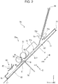
- the second unit 6 is provided on the transport path 69, and is provided with a pair of feed rollers 75 as a feed section that transports the medium P, a stack section 71 as a stacking portion that stacks the medium P, and a processing portion 70a that performs saddle-stitching on the medium stacked in the stack section 71.
- the processing portion 70a includes a binding mechanism 72 that binds the bundle M of media composed of a plurality of sheets of media P stacked on the stack section 71 at a binding position, and a pair of folding rollers 73 as a folding section that folds the bundle M of media at the binding position.
- the stack section 71 is provided with an aligning section 76 that aligns a downstream edge E1 of the stacked media P and a paddle 81.
- the pair of feed rollers 75 include a drive roller 75a driven by a drive source (not shown) and a driven roller 75b that is driven to rotate by the rotation of the drive roller 75a, and the drive roller 75a rotates under the control of the controller 25.
- the stack section 71 includes a support surface 85 that supports the medium P transported by the pair of feed rollers 75 in an inclined posture in which the downstream side in a transport direction +R faces downward, and the medium P is received and stacked between the support surface 85 and a facing surface 86 facing the support surface 85.
- the paddle 81 is provided between the pair of feed rollers 75 and the aligning section 76 in the transport direction +R and moves the medium P toward the aligning section 76 by rotating around a rotation shaft 82 while being in contact with the medium P.
- reference numeral G indicates a merging position G where the transport path 69 and the stack section 71 merge.
- the binding position in the present embodiment is a central section C in the transport direction +R of the media P stacked in the stack section 71.
- the medium P is sent to the stack section 71 from the transport path 69 by the pair of feed rollers 75.
- the stack section 71 is provided with the aligning section 76 that can abut on the downstream edge E1 of the media P stacked in the stack section 71 in the transport direction +R, and an abutting section 77 that can abut on an upstream edge E2 of the media P stacked in the stack section 71 in the transport direction +R.
- the aligning section 76 and the abutting section 77 are configured to be movable in both the transport direction +R of the medium P in the stack section 71 and a reverse direction -R thereof.
- the aligning section 76 and the abutting section 77 can be moved in the transport direction +R and the reverse direction -R by using a rack and pinion mechanism or a belt moving mechanism that operates by the power of a drive source (not shown), for example.
- the movements of the aligning section 76 and the abutting section 77 will be described in detail when the stacking operation in the stack section 71 is described.
- the binding mechanism 72 that binds the bundle M of media stacked in the stack section 71 at a predetermined position in the transport direction +R is provided downstream from the merging position G.
- the binding mechanism 72 is, for example, a stapler, and binds the bundle M of media at a binding section 72a that is an example of binding section.
- a plurality of binding sections 72a are provided at intervals in the X-axis direction that is the width direction of the medium.
- the binding mechanism 72 is configured to bind the bundle M of media with the central section C of the bundle M of media in the transport direction as a binding position.
- the pair of folding rollers 73 are provided downstream from the binding mechanism 72.
- the facing surface 86 is open at a position corresponding to a nip position N of the pair of folding rollers 73, and an entry path 78 for the bundle M of media from the stack section 71 to the pair of folding rollers 73 is formed.
- a slope is formed to guide the central section C, which is the binding position, from the stack section 71 to the nip position N.
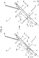
- a blade 74 that can switch between a retracted state of being retracted from the stack section 71 as shown in FIGS. 2 and 3 and an advancing state of advancing to the binding position of the bundle M of media stacked in the stack section 71 as shown in the left view of FIG. 4 is provided on the opposite side of the pair of folding rollers 73 with the stack section 71 interposed therebetween.
- Reference numeral 79 is a hole 79 provided in the support surface 85, and the blade 74 can pass through the hole 79.
- FIG. 2 shows a state in which a plurality of sheets of media P overlapped on the stack section 71 are stacked as the bundle M of media.
- the aligning section 76 is disposed such that the distance from the merging position G of the transport path 69 and the stack section 71 to the aligning section 76 is longer than the length of the medium P.
- the medium P is received in the stack section 71 without the upstream edge E2 of the medium P transported from the transport path 69 remaining in the transport path 69.
- the position of the aligning section 76 in the transport direction +R of the stack section 71 can be changed according to the size of the medium P.
- the binding processing of binding the central section C of the bundle M of media in the transport direction +R with the binding section 72a is performed.
- the central section C is displaced from the position of the binding section 72a, and therefore, as shown in the left view of FIG. 3 , the aligning section 76 is moved in the -R direction, and the central section C of the bundle M of media is arranged at a position facing the binding section 72a.
- the abutting section 77 is moved in the +R direction to abut on the upstream edge E2 of the bundle M of media.
- the aligning section 76 and the abutting section 77 align the downstream edge E1 and the upstream edge E2 of the bundle M of media, and the central section C of the bundle M of media is bound by the binding section 72a.
- the aligning section 76 is moved in the +R direction, and the bundle M of media are moved so that the bound central section C is arranged at a position facing the nip position N of the pair of folding rollers 73.
- the bundle M of media can be moved in the +R direction by moving only the aligning section 76 in the +R direction while keeping the bundle M of media in contact with the aligning section 76 by the own weight thereof.
- the abutting section 77 may be moved in the +R direction so as to maintain the abutting state on the upstream edge E2 of the bundle M of media.
- the blade 74 is advanced in a +S direction to bend the central section C toward the pair of folding rollers 73.
- the central section C of the bent bundle M of media passes through the entry path 78, and the bundle M of media are moved toward the nip position N of the pair of folding rollers 73.
- the pair of folding rollers 73 When the central section C of the bundle M of media is nipped by the pair of folding rollers 73, the pair of folding rollers 73 are rotated, and as shown in the right view of FIG. 4 , the bundle M of media are discharged toward the second tray 65 (see FIG. 1 ) while being folded at the central section C by the nip pressure of the pair of folding rollers 73. Further, after the central section C is nipped by the pair of folding rollers 73, the aligning section 76 moves in the +R direction, returns to the state of FIG. 2 , and prepares to receive the next medium P in the stack section 71.
- the transport path 69 may be provided with a folding line forming section that makes a folding line at the central section C of the medium P.
- the bundle M of media can be easily folded at the central section C by providing a folding line at the central section C which is the folding position by the pair of folding rollers 73.
- the maximum number of sheets of media stacked on the stack section 71 of the saddle-stitching and folding mechanism 70 is uniformly determined by considering the curl or a certain degree of increase in the amount of water in the medium due to ink ejection, when a degree of an actual curl or an increase in the amount of water is smaller than originally assumed, the number of media that can be processed will be unnecessarily suppressed, and on the contrary, when the degree of the actual curl or the increase in the amount of water is larger than originally assumed, a paper jam may occur in the saddle-stitching and folding mechanism 70.
- the controller 25 determines the maximum number of sheets of media stacked in the stack section 71, in other words, the upper limit of the number of media that can be sent to the stack section 71 based on the information on the swelling of the medium recorded by the line head 20.
- the maximum number of sheets of media will be referred to as the "maximum number of sheets in the stack section 71" or simply "maximum number of sheets”.
- the maximum number of sheets in the stack section 71 can be unnecessarily suppressed, and the possibility that the medium is jammed in the saddle-stitching and folding mechanism 70 can be suppressed.
- FIG. 5 shows a flow of determination processing regarding saddle-stitching, which is executed by the controller 25.
- the processing illustrated in FIG. 5 is realized by the controller 25 executing a program stored in a storage section (not shown) included in the controller 25.
- the controller 25 receives a series of commands for starting the execution of recording job from the operation section 19 (see FIG. 1 )
- the controller 25 determines the maximum number of sheets in the stack section 71 (step S102). Details of this step S102 will be described later. If the recording job does not include saddle-stitching (No in step S101), the execution of the recording job is started based on designated settings (step S106).
- step S103 it is determined whether or not the number of sheets subject to saddle-stitching designated by a user exceeds the maximum number of sheets determined in step S102 (step S103), and if the maximum number of sheets is exceeded (Yes in step S103), a warning display is displayed on a display panel (not shown) included in the operation section 19 (see FIG. 1 ) (step S104).
- This warning display can be, for example, a warning message display that "The number of sheets subject to saddle-stitching exceeds the upper limit. Please select processing.”
- the controller 25 performs designated processing based on the user's instruction regarding this warning. As a result, even when the number of sheets designated by the user exceeds the maximum number of sheets in the stack section 71, that is, when there is a possibility that a problem may occur, usability is improved compared to the case where processing is uniformly stopped.
- the above-described "designated processing” includes first processing, second processing, and the cancellation of a recording job.
- the user inputs an instruction via the operation section 19 to perform either the first processing, the second processing, or the cancellation of the recording job.
- the first processing the number of sheets designated by the user in the saddle-stitching is maintained, and the subsequent processing is performed as it is while maintaining the recording quality by the line head 20 (Yes in step S105), and by selecting this processing, the user can try the processing as originally planned while recognizing the possibility of a jam.
- the second processing the number of sheets designated by the user in the saddle-stitching is maintained, at least one of the recording quality by the line head 20 and the transport condition of the medium from the line head 20 to the stack section 71 is changed, and processing is performed so that the number of sheets designated by the user is less than or equal to the maximum number of sheets in the stack section 71.
- this processing is referred to as a jam prevention mode (step S106).
- the jam prevention mode the user can perform the processing in the saddle-stitching and folding mechanism 70 while maintaining the number of sheets designated by the user as originally planned and suppressing a jam.
- the jam prevention mode is to change at least one of the recording quality at the time of recording by the line head 20, paper transport conditions from the line head 20 to the stack section 71, the transport speed in the loop-shaped transport path 52 in the drying section 50, the number of turns of the medium in the loop-shaped transport path 52, and the heating temperature by the heater in the drying section 50.
- the change of the recording quality at the time of recording by the line head 20 includes, for example, decreasing the recording density.
- the change of the paper transport conditions is mainly for promoting the drying of the paper, and examples thereof include lowering the paper transport speed and stopping the paper in the middle of the paper transport path.
- the change of the transport speed in the loop-shaped transport path 52 may be, for example, decreasing the transport speed.
- the number of turns of the medium in the loop-shaped transport path 52 can be changed, for example, by increasing the number of turns.
- Examples of changing the heating temperature by the heater in the drying section 50 include raising the heating temperature.
- the above-described first processing and second processing are examples, and other processing may be used, or third processing or more processing may be added and processing may be selected therefrom. As an example of such other processing, it may be possible to prompt the user to change the paper type or to reduce the number of sheets designated by the user in the saddle-stitching.
- step S105 When the first processing is selected (Yes in step S105) and the second processing is selected (Yes in step S106), the controller 25 starts the execution of the recording job according to the contents (step S107).
- step S107 When neither the first processing nor the second processing is selected, that is, when the cancellation of a recording job is selected (No in step S105 and No in step S106), the controller 25 stops the execution of the recording job.
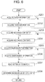
- FIG. 6 shows a flow of processing of determining the maximum number of sheets in the stack section 71, which is executed by the controller 25.
- the processing shown in FIG. 6 is realized by the controller 25 executing a program stored in a storage section (not shown) included in the controller 25.
- the controller 25 determines the maximum number of sheets in the stack section 71 based on the information on the swelling of the medium on which recording is performed.
- the swelling of the medium is swelling that occurs when the medium absorbs the ink when the medium is paper and the liquid is ink, and the swelling further causes a curl.
- paper will be described as an example of the medium.
- the information on the swelling of the paper is information on at least one of all factors that affect the swelling of the paper.
- Examples of information relating to factors that affect the swelling of the paper include paper information and recorded contents.
- the paper information includes factors such as paper size, paper length and width, paper thickness, grain direction, presence or absence of coat layer, and the like.
- the paper information can be acquired from a printer driver.
- the grain direction may be input by the user in the operation section 19, or other paper information may be stored in advance in association with the paper size and the paper length and width depending on the destination of the apparatus. This is because the grain direction of the paper has a certain tendency depending on the destination of the apparatus, specifically, the country in which the apparatus is used.
- a global positioning system GPS may be provided in the recording system 1 and the grain direction of the paper may be determined based on the information.
- the recorded contents include factors such as the position of the recording area on the paper, the size of the recording area, the shape of the recording area, the amount of ink ejected in the recording area, the presence and absence of double-sided recording, and a difference in the recorded contents between the front surface and the back surface in the case of double-sided recording.
- paper having a coat layer may be referred to as "glossy paper” or “ink jet paper” on a printer driver, and it can be said that such paper is less likely to swell and curl than paper having no coat layer, which is referred to as "plain paper” on the printer driver.
- the paper is divided into several areas, and areas a1, a2, a3, a4, a5, and a6 are set like paper P shown in FIG.
- the unevenness of the amount of ink ejected in the area of the paper can be obtained by the difference in the amount of ink ejected between the area having the largest amount of ink ejected and the area having the smallest amount of ink ejected.
- the easier the paper is to curl because the difference in the amount of water between the front surface and the back surface is large as compared with the case where double-sided recording is performed.
- double-sided recording it can be said that the more remarkable the difference in the recorded contents between the front surface and the back surface is, the more uneven the swelling is and the easier the paper is to curl.
- the difference in the recorded contents between the front surface and the back surface can be obtained, for example, by the difference between the amount of ink ejected on the front surface and the amount of ink ejected on the back surface.
- the controller 25 may consider information on factors that affect the dry state of the recording paper.
- the information on the factors that affect the dry state of the sheet include environmental information.
- the environment information includes factors such as temperature and humidity, for example.
- the recording unit 2 is provided with an environment information acquisition section 18 (see FIG. 1 ), and the controller 25 (see FIG. 1 ) can acquire the temperature and humidity inside the recording unit 2 from the environment information acquisition section 18.
- the environmental information for example, the lower the temperature is or the higher the humidity is, the more difficult it is to dry, and therefore the frictional force between the sheets tends to be large, and the stiffness of the sheets tends to weaken. That is, it can be said that a jam is likely to occur.
- the storage section of the controller 25 holds the setting information of the maximum number of sheets determined based on the above properties, and the controller 25 refers to the setting information of the maximum number of sheets to determine the maximum number of sheets in the stack section 71.
- Information on the swelling of these sheets such as the paper information, the recorded contents, and the environmental information, may be considered, or any one or two thereof may be considered.
- the setting can be performed by a user operation, and the user can select the information to be considered by the operation section 19 (see FIG. 1 ) and save the selection as a set value.
- the controller 25 acquires the paper information (step S202), when acquiring the recorded contents (Yes in step S203), acquires the recorded contents (step S204), and when acquiring the environment information (Yes in step S205), acquires the environment information (step S206). Then, the setting information is read (step S207), and the maximum number of sheets is determined (step S208).
- Table 1 shows an example of the setting information.
- a recording density Pd (%) of the recorded contents and a humidity Hm (%) of the environment information are used as the information on the swelling of the sheet.
- the maximum amount of ink to be ejected (g) in the recordable area of one sheet can be obtained from the maximum amount of ink to be ejected (g) per unit area by the line head 20 provided in the recording unit 2. Further, the recording density (%) is not limited thereto, and may be the ratio of the area where ink is ejected to the area of one sheet.
- Table 1 Hm ⁇ Pd 0% 10% 20% ... 80% 90% 100% 0% 20 20 ... 16 15 15 10% 20 20 20 ... 16 15 15 20% 20 20 20 ... 16 15 15 ⁇ ⁇ ⁇ ⁇ ⁇ ⁇ 80% 20 20 20 ... 15 14 14 90% 18 18 18 ... 14 13 13 100% 18 18 18 ... 13 13 13 13 13
- the numerical values in Table 1 are an example of the maximum number of sheets in the stack section 71.
- the maximum number of sheets is 20.
- Such setting information is set and stored for each paper type.
- the maximum number of sheets may be calculated by a mathematical expression.
- a coefficient k may be set for each factor related to the swelling of the paper with respect to a specified value M of the maximum number of sheets, the specified value M may be sequentially multiplied by the coefficient k, and the finally obtained value may be used as the maximum number of sheets in the stack section 71.
- the specified value M can be obtained by dividing the maximum height of stacking in the stack section 71 by the sheet thickness.
- Table 2 shows an example of a coefficient ka set according to the humidity Hm (%).
- the maximum number of sheets in the stack section 71 can be obtained by setting the coefficient for each condition regarding the factors related to the swelling of the paper and multiplying the coefficient by the specified value M of the maximum number of sheets.
- Table 2 Hm ka 0% 1.0 10% 1.0 20% 1.0 ⁇ ⁇ 80% 1.0 90% 0.9 100% 0.9
- the sheet size, the sheet thickness, the grain direction, and the presence and absence of the coat layer can be used to determine the direction and the amount of deformation of the sheet due to swelling and then a curl.
- a curl due to swelling of the paper is likely to occur in the direction intersecting the grain direction, and the larger the size of the paper in the direction intersecting the grain direction, the greater the amount of deformation due to the curl. Since the maximum height of stacking in the stack section 71 is reduced by the amount of deformation of the sheets due to the curl, the maximum number of sheets in the stack section 71 is reduced accordingly.
- the paper is supported in the stack section 71 in an inclined posture so as to be inclined downward in the transport direction +R, the paper is easily bent in the transport direction +R on the stack section 71 due to the action of the own weight thereof. Therefore, when the grain direction of the paper is along the X-axis direction, that is, the medium width direction, the rigidity in the transport direction +R is lower than that in the case where the grain direction is along the transport direction +R, and bending is relatively likely to be formed. In this way, the information on the grain direction can also be used to determine the direction and amount of deformation of the sheet.
- the controller 25 determines the maximum number of sheets in the stack section 71 based on the acquired information on the grain direction, it is possible to appropriately optimize the maximum number of sheets for each processing.
- the controller 25 determines the maximum number of sheets in the stack section 71 based on the acquired information on the sheet thickness, it is possible to appropriately optimize the maximum number of sheets for each processing.
- the controller 25 determines the maximum number of sheets based on the acquired information on the amount of ink ejected onto the paper, it is possible to appropriately optimize the maximum number of sheets for each processing.
- the controller 25 can also determine the maximum number of sheets based on the acquired information on the amount of ink. That is, the binding mechanism 72 has many irregularities on the surface through which the paper passes due to the property thereof, and the paper is easily caught, but on the contrary, it can be said that, in an area of the paper that does not pass between the binding mechanism 72 and the stack section 71, even if a curl due to swelling occurs, the paper does not get caught in the irregularities of the binding mechanism 72. Specifically, in FIG.
- the area that enters from a position k into the +R direction is an area where the paper is easily caught in the binding mechanism 72 due to the curl caused by the swelling.
- FIG. 8 shows an example of the sheet P, and an area a0 is an area that enters from the position k in FIG. 2 in the +R direction, and an area b0 is the other area. Therefore, the controller 25 can determine the maximum number of sheets in the stack section 71 in consideration of the recorded contents in the area a0 without considering the recorded contents in the area b0. As a result, it is not necessary to unnecessarily suppress the maximum number of sheets in the stack section 71, and it is possible to more appropriately optimize the maximum number of sheets in the stack section 71.
- the recording unit 2 including the line head 20 is an independent unit
- the second unit 6 including the stack section 71 and the binding mechanism 72 is an independent unit
- the controller 25 is provided in the recording unit 2 and is configured to control the second unit 6 from the recording unit 2.
- a controller (not shown) that controls the saddle-stitching and folding mechanism 70 is provided for the second unit 6, and information on swelling may be sent from the controller 25 of the recording unit 2 to the controller, and the controller included in the second unit 6 may control the saddle-stitching and folding mechanism 70 based on the information.
- the controller that controls the saddle-stitching and folding mechanism 70 may be provided in an apparatus other than the recording unit 2 and the second unit 6. Further, not only the second unit 6 but also the intermediate unit 3 and the first unit 5 are respectively provided with controllers (not shown), and these controllers may control the operations of the intermediate unit 3 and the first unit 5 based on the information from the controller 25 of the recording unit 2.
- the intermediate unit 3 and the first unit 5 may be omitted.
- the recording unit 2 and the second unit 6 may be independent units, or the recording unit 2 and the second unit 6 may be integrated. That is, more specifically, the recording system may be configured to include the line head 20 and the saddle-stitching and folding mechanism 70. As described above, in the present specification, the recording system 1 may be either a collection of independent units or a single unit.
Landscapes
- Engineering & Computer Science (AREA)
- Mechanical Engineering (AREA)
- Physics & Mathematics (AREA)
- General Physics & Mathematics (AREA)
- Textile Engineering (AREA)
- Folding Of Thin Sheet-Like Materials, Special Discharging Devices, And Others (AREA)
- Handling Of Sheets (AREA)
- Ink Jet (AREA)
- Accessory Devices And Overall Control Thereof (AREA)
- Controlling Sheets Or Webs (AREA)
- Pile Receivers (AREA)
Abstract
Description
- The present application is based on, and claims priority from
JP Application Serial Number 2019-175247, filed September 26, 2019 - The present disclosure relates to a recording system including a recording portion that performs recording on a medium, a stacking portion that stacks the medium recorded by the recording portion, and a processing portion that processes a bundle of media stacked on the stacking portion. Further, the present disclosure also relates to a processing apparatus including a stacking portion that stacks a medium recorded by a recording portion that performs recording on the medium, and a processing portion that processes a bundle of media stacked on the stacking portion.
- A media processing apparatus that performs predetermined processing on a medium includes an apparatus that performs stapling or punching processing on a plurality of sheets of media overlapped in a stacking portion that stacks the media, and an apparatus that forms a booklet by performing saddle-stitching of binding the widthwise centers of a plurality of sheets of media overlapped in the stacking portion and then folding the media at a binding position. Such a media processing apparatus is configured as an independent unit and is employed in various forms, such as when installed outside a recording apparatus and constitutes one system as a whole or when built in one housing together with a recording portion for recording on a medium to constitute one system.
- As an example,
JP-A-2016-023085 - When recording is performed by ejecting liquid onto the medium, the medium swells and curls by absorbing the liquid. Therefore, if the maximum number of sheets of media in the stacking portion of the media processing apparatus is uniformly determined in consideration of a certain degree of this curl, when a degree of an actual curl is smaller than originally assumed, the number of media that can be processed may be unnecessarily suppressed, and on the other hand, when the degree of the actual curl is larger than originally assumed, a paper jam may occur inside the apparatus.
- The present disclosure is a recording system of the present disclosure including a recording portion that performs recording on a medium, a stacking portion that stacks the medium recorded by the recording portion, and a processing portion that processes a bundle of media stacked on the stacking portion, in which a controller that controls feeding of a medium to the stacking portion determines the maximum number of sheets of media to be stacked on the stacking portion, based on information on the swelling of the medium recorded by the recording portion.
-
-
FIG. 1 is a view showing an overall configuration of a recording system. -
FIG. 2 is a side view of a saddle-stitching and folding mechanism. -
FIG. 3 is a view showing a movement of a medium in the saddle-stitching and folding mechanism. -
FIG. 4 is a view showing movement of the medium in the saddle-stitching and folding mechanism. -
FIG. 5 is a flowchart showing a flow of determination processing regarding saddle-stitching. -
FIG. 6 is a flowchart showing a flow of processing of determining the maximum number of sheets in a stack section. -
FIG. 7 is a view showing an example of a method for obtaining unevenness of an amount of ink ejected on a sheet. -
FIG. 8 is a view showing an example of an area of a sheet that passes between a binding unit and the stack section. - The present disclosure will be schematically described below. According to a first aspect of the present disclosure, there is provided a recording system including a recording portion that performs recording on a medium, a stacking portion that stacks the medium recorded by the recording portion, and a processing portion that processes a bundle of media stacked on the stacking portion, in which a controller that controls feeding of the medium to the stacking portion determines the maximum number of sheets of media to be stacked on the stacking portion, based on information on swelling of the medium recorded by the recording portion.
- According to this aspect, since the controller that controls feeding of a medium to the stacking portion determines the maximum number of sheets of media to be stacked on the stacking portion, based on information on swelling of the medium recorded by the recording portion, the maximum number of sheets may be optimized for each processing from the information on the swelling of the medium that actually occurs. Accordingly, the maximum number of sheets does not match the actual swelling of the medium, and as a result, it is possible to prevent the maximum number of sheets from being unnecessarily suppressed, and it is possible to suppress the possibility that the medium is jammed in the stacking portion.
- In a second aspect of the recording system according to the first aspect, the information on the swelling includes information on a grain direction when the medium is paper, and the controller determines the maximum number of sheets based on acquired information on the grain direction. When the medium is paper, the tendency of a curl due to swelling changes depending on the grain direction, but according to this aspect, since the information on the swelling includes information on the grain direction when the medium is paper and the controller determines the maximum number of sheets based on the acquired information on the grain direction, it is possible to appropriately optimize the maximum number of sheets for each processing. The grain is a flow of fibers formed along the longitudinal direction or the lateral direction of paper, depending on the conditions in the manufacturing process of the paper, and the paper has a property that it is hard to bend in the direction orthogonal to the grain and easy to bend in the direction parallel to the grain.
- In a third aspect of the recording system according to the first or the second aspect, the information on the swelling includes information on a thickness of the medium, and the controller determines the maximum number of sheets based on acquired information on the thickness. A tendency of a curl due to the swelling of the medium changes according to the thickness of the medium, but according to this aspect, since the information on the swelling includes information on thickness of the medium, and the controller determines the maximum number of sheets based on acquired information on the thickness, it is possible to appropriately optimize the maximum number of sheets for each processing.
- In a fourth aspect of the recording system according to any one of the first to third aspects, the recording portion performs recording by ejecting a liquid onto the medium, the information on the swelling includes information on an amount of the liquid ejected onto the medium, and the controller determines the maximum number of sheets based on acquired information on the amount of the liquid.
- The tendency of the curl due to swelling of the medium changes depending on the amount of liquid ejected onto the medium, but according to this aspect, since the information on the swelling includes information on an amount of the liquid ejected onto the medium, and the controller determines the maximum number of sheets based on acquired information on the amount of the liquid, it is possible to appropriately optimize the maximum number of sheets for each processing.
- In a fifth aspect of the recording system according to any one of the first to the fourth aspects, when the number of bundles of media to be processed by the processing portion, which is designated by a user, exceeds the maximum number of sheets determined based on the information on the swelling, the controller issues a warning to the user, and designated processing is performed based on a user's instruction regarding the warning.
- Even if the number of sheets of a bundle of media to be processed by the processing portion, which is designated by the user, exceeds the maximum number of sheets determined based on the information on the swelling, that is, if there is a possibility that a problem may occur, the processing is stopped uniformly, and therefore the convenience for the user may be reduced. According to this aspect, when the number of the bundles of media to be processed by the processing portion, which is designated by a user, exceeds the maximum number of sheets determined based on the information on the swelling, the controller issues a warning to the user, and designated processing is performed based on a user's instruction regarding the warning, and therefore usability is improved.
- In a sixth aspect of the recording system according to the fifth aspect, the designated processing based on the user's instruction includes first processing of performing processing while maintaining the number of bundles of media to be processed by the processing portion, which designated by the user and maintaining a recording quality in the recording portion, and second processing of performing processing by changing at least one of the recording quality in the recording portion and transport conditions of the medium from the recording portion to the stacking portion so that the number of the bundles of media to be processed by the processing portion is equal to or less than the maximum number of sheets while maintaining the number of the bundles of media to be processed in the processing portion, which is designated by the user.
- According to this aspect, by selecting the first processing, the user can try the processing as originally planned while recognizing the possibility of the jam occurrence. By selecting the second processing, the user can perform the processing in the processing portion while maintaining the number of sheets to be processed as originally planned and suppressing a jam.
- In a seventh aspect of the recording system according to any one of the first to sixth aspects, the processing portion includes a binding section that binds the media at a position facing the stacking portion, and a folding section that folds the media at a binding position of the binding section. According to this aspect, in a configuration in which the processing portion includes a binding section that binds the media at a position facing the stacking portion, and a folding section that folds the media at the binding position by the binding section, the operational effect of any of the first to fifth aspects described above may be obtained.
- In an eighth aspect of the recording system according to any one of the first to third aspects, the recording portion performs recording by ejecting a liquid onto the medium, the processing portion includes a binding section that binds the media at a position facing the stacking portion, and a folding section that folds the media at a binding position of the binding section, the information on the swelling includes information on an amount of the liquid ejected to an area of the medium passing between the binding section and the stacking portion, and the controller determines the maximum number of sheets based on acquired information on the amount of the liquid.
- The binding section has many irregularities on the surface through which the medium passes due to the property thereof, and the medium is easily caught, but on the contrary, it can be said that, in an area of the medium that does not pass between the binding section and the stacking portion, even if a curl occurs, the medium does not get caught in the irregularities. In addition, it can be said that the area between the binding section and the stacking portion tends to be narrow and is greatly affected by the friction between the medium and other members and the friction between the media, and a jam is likely to occur. Therefore, in this aspect, since the information on the swelling includes information on an amount of the liquid ejected to an area of the medium passing between the binding section and the stacking portion, and the controller determines the maximum number of sheets based on acquired information on the amount of the liquid, it is not necessary to suppress the maximum number of sheets unnecessarily, and it is possible to optimize the maximum number of sheets more appropriately.
- In a ninth aspect of the recording system according to any one of the first to eighth aspects, the recording portion constitutes an independent recording unit, the stacking portion and the processing portion constitute an independent processing unit, and the controller is provided in the recording unit and controls the processing unit from the recording unit. According to this aspect, in a configuration in which the recording portion constitutes an independent recording unit, the stacking portion and the processing portion constitute an independent processing unit, the controller is provided in the recording unit, and the recording unit controls the processing unit, the operational effect of any of the first to seventh aspects described above may be obtained.
- In a tenth aspect of the recording system according to any one of the first to eighth aspects, the recording portion includes an independent recording unit, the stacking portion and the processing portion includes an independent processing unit, and the controller is provided in the processing unit and the information on the swelling is sent from the recording unit to the processing unit.
- According to this aspect, in a configuration in which the recording portion constitutes an independent recording unit, the stacking portion and the processing portion constitute an independent processing unit, the controller is provided in the processing unit, and the information on the swelling is sent from the recording unit to the processing unit, the operational effect of any of the first to seventh aspects described above may be obtained.
- According to an eleventh aspect of the present disclosure, there is provided a processing apparatus including a stacking portion that stacks a medium recorded by a recording portion that performs recording on the medium, and a processing portion that processes a bundle of media stacked on the stacking portion, in which the maximum number of sheets of media stacked on the stacking portion is determined based on information on swelling of the medium recorded by the recording portion.
- According to this aspect, since the maximum number of sheets of media stacked in the stacking portion is determined based on the information on the swelling of the medium recorded by the recording portion, the maximum number of sheets of media can be optimized for each processing from the information on the swelling of the medium that actually occurs. As a result, it is possible to prevent the maximum number of sheets from being unnecessarily suppressed, and it is possible to suppress the possibility that the medium is jammed inside the apparatus.
- Hereinafter, the present disclosure will be specifically described. The XYZ coordinate system shown in each drawing is an orthogonal coordinate system, in which an X-axis direction indicates the apparatus depth direction, a Y-axis direction indicates the apparatus width direction, a Z-axis direction indicates the apparatus height direction.
- As an example, a recording system 1 shown in
FIG. 1 includes arecording unit 2, anintermediate unit 3, afirst unit 5, and a second unit 6 as a processing apparatus or a processing unit that is attachable to and detachable from thefirst unit 5 in order from the right side to the left side inFIG. 1 . - The
recording unit 2 performs recording on a transported medium. Theintermediate unit 3 receives the medium after recording from therecording unit 2 and transfers the medium to thefirst unit 5, and mainly has a function of reversing the medium and a function of promoting drying of the medium. Thefirst unit 5 is provided with adrying section 50 that performs drying processing on the received medium, and anedge binding section 42 that performs edge binding processing that binds the edges of the media after recording in therecording unit 2 in a bundle. The second unit 6 is provided with a saddle-stitching andfolding mechanism 70 that binds and folds the center of a bundle of media after recording in therecording unit 2 into a booklet. In the following, the processing of binding the center of the bundle of media after recording and the processing of subsequently folding the bundle of media will be simply referred to as "saddle-stitching". Hereinafter, therecording unit 2, theintermediate unit 3, thefirst unit 5, and the second unit 6 will be described in detail in this order. - The
recording unit 2 is configured as a multifunction machine including aprinter section 10 having aline head 20 as a recording portion that performs recording on a medium and ascanner section 11. In the present embodiment, theline head 20 is configured as a so-called ink jet recording head that ejects ink, which is an example of a liquid, onto a medium to perform recording. At the bottom of theprinter section 10, acassette storage section 14 including a plurality ofmedium storage cassettes 12 is provided. A medium P stored in themedium storage cassette 12 is sent to the recording area by theline head 20 through a feedingpath 21 shown by a solid line, and a recording operation is performed. The medium after recording by theline head 20 is sent to either afirst discharge path 22 which is a path for discharging the medium to apost-recording discharge tray 13 provided above theline head 20 or asecond discharge path 23 which is a path for sending the medium to theintermediate unit 3. - In
FIG. 1 , thefirst discharge path 22 is shown by a broken line, and thesecond discharge path 23 is shown by a dashed line. Thesecond discharge path 23 extends in the +Y direction of therecording unit 2 and transfers the medium to a receivingpath 30 of the adjacentintermediate unit 3. - Further, the
recording unit 2 includes a reversingpath 24 indicated by a chain double-dashed line inFIG. 1 , and is configured to be capable of double-sided recording in which the medium is reversed and recording is performed on the second surface after recording on the first surface of the medium. In each of the feedingpath 21, thefirst discharge path 22, thesecond discharge path 23, and the reversingpath 24, one or more pairs of rollers (not shown) are arranged as an example of a means for transporting the medium. - The
recording unit 2 is provided with acontroller 25 that controls operations related to the transport and recording of the medium in therecording unit 2. In the recording system 1, therecording unit 2, theintermediate unit 3, thefirst unit 5, and the second unit 6 are mechanically and electrically coupled to each other and are configured so that the medium can be transported from therecording unit 2 to the second unit 6. Thecontroller 25 in the present embodiment can control various operations in theintermediate unit 3, thefirst unit 5, and the second unit 6 coupled to therecording unit 2. - The
recording unit 2 includes anoperation section 19, and is configured so that various settings and execution commands regarding various kinds of processing in therecording unit 2, theintermediate unit 3, thefirst unit 5, and the second unit 6 can be input from theoperation section 19. In addition, theoperation section 19 includes a display panel (not shown), and is configured to display various information on this display panel. When an external computer (not shown) is coupled to the recording system 1, various settings and execution commands similar to the various settings and execution commands performed by theoperation section 19 can be performed in this external computer. - Next, the
intermediate unit 3 will be described. Theintermediate unit 3 shown inFIG. 1 transfers the medium received from therecording unit 2 to thefirst unit 5. Theintermediate unit 3 is disposed between therecording unit 2 and thefirst unit 5. The medium transported through thesecond discharge path 23 of therecording unit 2 is received by theintermediate unit 3 through the receivingpath 30 and transported toward thefirst unit 5. The receivingpath 30 is shown by a solid line inFIG. 1 . - In the
intermediate unit 3, there are two transport paths for transporting the medium. A first transport path is a path from the receivingpath 30 to a mergingpath 33 via afirst switchback path 31 shown by a dotted line inFIG. 1 . A second path is a path from the receivingpath 30 to the mergingpath 33 via asecond switchback path 32 shown by a chain double-dashed line inFIG. 1 . Thefirst switchback path 31 is a path for receiving the medium in an arrow A1 direction and then switching back the medium in an arrow A2 direction. Thesecond switchback path 32 is a path for receiving the medium in an arrow B1 direction and then switching back the medium in an arrow B2 direction. - The receiving
path 30 branches into thefirst switchback path 31 and thesecond switchback path 32 at abranch section 35. Thebranch section 35 is provided with a flap (not shown) that switches the destination of the medium to either thefirst switchback path 31 or thesecond switchback path 32. - Further, the
first switchback path 31 and thesecond switchback path 32 merge at a mergingsection 36. Therefore, whether the medium is sent from the receivingpath 30 to thefirst switchback path 31 or thesecond switchback path 32, the medium can be transferred to thefirst unit 5 via thecommon merging path 33. - The
intermediate unit 3 receives the medium from therecording unit 2 in the receivingpath 30 with the most recent recording surface of theline head 20 facing upward, but in the mergingpath 33, the medium is curved and reversed, and the most recent recording surface faces downward. Therefore, the medium with the most recent recording surface facing downward is transferred from the +Y direction of theintermediate unit 3 to afirst transport path 43 of thefirst unit 5. In each of the receivingpath 30, thefirst switchback path 31, thesecond switchback path 32, and the mergingpath 33, one or more pairs of rollers (not shown) are arranged as an example of a means for transporting the medium. - When recording is continuously performed on a plurality of media in the
recording unit 2, the medium that has entered theintermediate unit 3 is alternately sent to the transport path that passes through thefirst switchback path 31 and the transport path that passes through thesecond switchback path 32. As a result, the throughput of medium transport in theintermediate unit 3 can be increased. - When recording is performed by ejecting a liquid, specifically ink, onto a medium like the
line head 20 of the present embodiment, if the medium is wet when the processing is performed by thefirst unit 5 and the second unit 6 in the subsequent stage, the recording surface may be rubbed or the medium may have poor consistency. It is possible to lengthen the transport time until the medium after recording is sent to thefirst unit 5 and further dry the medium before the medium reaches thefirst unit 5 or the second unit 6 by transferring the medium after recording from therecording unit 2 to thefirst unit 5 via theintermediate unit 3. Regarding First Unit - Subsequently, the
first unit 5 will be described. Thefirst unit 5 shown inFIG. 1 includes a receivingsection 41 that receives the medium from theintermediate unit 3 in the lower side in the -Y direction. The medium transported through the mergingpath 33 of theintermediate unit 3 enters thefirst unit 5 from the receivingsection 41 and is transferred to thefirst transport path 43. - The
first unit 5 includes the dryingsection 50 that processes the medium received from the receivingsection 41, and theedge binding section 42 that processes the medium received from the receivingsection 41 or the medium processed by the dryingsection 50. Thefirst unit 5 includes thefirst transport path 43 for sending the medium received from the receivingsection 41 to theedge binding section 42, and asecond transport path 44 that branches from thefirst transport path 43 at a second branch section D2 and for sending the medium to thedrying section 50. The second branch section D2 is provided with a flap (not shown) that switches the destination of the medium between thefirst transport path 43 and thesecond transport path 44. - The
edge binding section 42 is a component that performs edge binding processing of binding the edge of the medium, such as a corner on one side of the medium or a side of one side of the medium. Theedge binding section 42 includes a stapler as an example. The dryingsection 50 is a component that performs drying processing on the medium. In the present embodiment, the dryingsection 50 heats the medium to dry the medium. Although the detailed configuration of the dryingsection 50 will be described later, the medium after the drying processing by the dryingsection 50 is sent to either theedge binding section 42 or the saddle-stitching andfolding mechanism 70 provided in the second unit 6. - Further, the
first unit 5 includes apunching section 46 that performs punch processing on the medium received from the receivingsection 41. The punchingsection 46 is provided at a position near the receivingsection 41 on thefirst transport path 43 through which the medium received by thefirst unit 5 passes, and is configured to be able to perform punch processing upstream of thefirst transport path 43. The medium received from the receivingsection 41 may or may not be punched by the punchingsection 46. - The medium received from the receiving
section 41 can be sent to aprocessing tray 48 or the second unit 6 described later through thefirst transport path 43 shown inFIG. 1 . In theprocessing tray 48, the media are stacked on theprocessing tray 48 with the rear edges in the transport direction aligned. When a predetermined number of the media P are stacked on theprocessing tray 48, the edge binding processing by theedge binding section 42 can be performed on the rear edge of the media P. Thefirst unit 5 includes asecond discharge section 62 that discharges the medium in the +Y direction. Thefirst unit 5 includes thesecond discharge section 62, afirst discharge section 61 and athird discharge section 63, which will be described later, and is configured to discharge the medium therefrom. - The medium processed by the
edge binding section 42 is discharged from thesecond discharge section 62 to the outside of the apparatus of thefirst unit 5 by a discharge section (not shown), and is stacked on afirst tray 40 that receives the medium discharged from thesecond discharge section 62. Thefirst tray 40 is provided so as to project from thefirst unit 5 in the +Y direction. In the present embodiment, thefirst tray 40 includes abase section 40a and anextension section 40b, and theextension section 40b is configured to be stored in thebase section 40a. - In addition, a
third transport path 45, which branches from thefirst transport path 43 at a third branch section D3 downstream from the second branch section D2, is coupled to thefirst transport path 43. The third branch section D3 is provided with a flap (not shown) that switches the destination of the medium between thefirst transport path 43 and thethird transport path 45. - An
upper tray 49 is provided above thefirst unit 5. Thethird transport path 45 extends from the third branch section D3 to the above-describedthird discharge section 63, and the medium transported through thethird transport path 45 is discharged from thethird discharge section 63 to theupper tray 49 by a discharge section (not shown). That is, the medium received from the receivingsection 41 can be discharged to theupper tray 49 without passing through theedge binding section 42. - The
first transport path 43 is provided with an overlappingpath 64 that branches from thefirst transport path 43 at a first branch section D1 and merges again with thefirst transport path 43 at a first merging section G1. The overlappingpath 64 includes an overlappingsection 47 that overlaps two media and sends the media to thedrying section 50 or theedge binding section 42. The preceding medium to be transported in advance is sent to the overlappingpath 64, and the preceding medium and the succeeding medium can be overlapped and transported downstream from the first merging portion G1 by merging the succeeding medium and the preceding medium transported through thefirst transport path 43 at the first merging portion G1. The overlappingsection 47 may be configured to have a plurality of overlappingpaths 64 and overlap three or more media and send the media downstream. - In the
first unit 5, the overlappingsection 47 is located vertically below the dryingsection 50, and the dryingsection 50, theedge binding section 42, and the overlappingsection 47 have a section that overlaps when viewed in the vertical direction, that is, when viewed from the top surface. Only dryingsection 50 and the overlappingsection 47 or only theedge binding section 42 and the overlappingsection 47 may be overlapped. The size of the apparatus can be reduced by suppressing an increase in the horizontal dimension of the apparatus by arranging the dryingsection 50, theedge binding section 42, and the overlappingsection 47 in such a positional relationship. - In the
first unit 5, in each of thefirst transport path 43, thesecond transport path 44, and thethird transport path 45, a pair of rollers (not shown) are arranged as an example of a means for transporting a medium. - Subsequently, the drying
section 50 provided in thefirst unit 5 will be described. The dryingsection 50 includes a pair ofheat rollers 51 as a drying section that performs drying processing of the medium, and a loop-shapedtransport path 52 including the pair ofheat rollers 51 and capable of circularly transporting the medium. Thesecond transport path 44 branched from thefirst transport path 43 merges with the loop-shapedtransport path 52 upstream of the pair ofheat rollers 51, and the medium can be fed by a pair oftransport rollers 68 provided in thesecond transport path 44 and introduced into the loop-shapedtransport path 52. - In the pair of
heat rollers 51, the lower roller is a drying drive roller driven by a drive source (not shown) in the present embodiment, and the upper roller is a drying driven roller driven by the rotation of the drying drive roller. The drying drive roller is heated by a heater (not shown), whereby the drying drive roller generates heat and the medium is dried. However, as long as at least one of the rollers forming the pair ofheat rollers 51 is heated, both rollers may be heated. - However, the medium sent from the
intermediate unit 3 enters thesecond transport path 44 from the receivingsection 41 of thefirst unit 5 via thefirst transport path 43 with the most recent recording surface facing downward. Then, the medium is nipped by the pair ofheat rollers 51 with the most recent recording surface facing downward. Therefore, it is preferable that the heated roller of the pair ofheat rollers 51 be a roller that comes into contact with the most recent recording surface of the medium. - Since the drying section includes the loop-shaped
transport path 52 and is configured to be capable of circularly transporting the medium in the loop-shapedtransport path 52, it is possible to perform drying processing by the pair of heat rollers 51 a plurality of times by circularly transporting the medium a plurality of times. Therefore, the medium can be dried more reliably. Further, by providing the loop-shapedtransport path 52, it is possible to suppress an increase in the cost of the apparatus and power consumption as compared with a case where a plurality of pairs ofheat rollers 51 are provided in the transport path, for example. - In the recording system 1, the heating by the pair of
heat rollers 51 is controlled by thecontroller 25 provided in therecording unit 2. Thecontroller 25 can control the heating of the pair ofheat rollers 51 according to conditions. Examples of the conditions include the ejection amount of ink ejected onto the medium during recording in therecording unit 2, whether the recording on the medium is double-sided recording or single-sided recording, environmental conditions such as temperature and humidity when drying, in addition to media type, rigidity, thickness, basis weight, and the like. By controlling the heating by the pair ofheat rollers 51 according to these conditions, the medium can be dried more appropriately. Examples of the heating control by the pair ofheat rollers 51 include heating or not heating, the temperature when heating, whether or not to use residual heat when heating, the timing of starting heating of the pair ofheat rollers 51, and the like. - Further, in the pair of
heat rollers 51, one drying driven roller is pressed against the other drying drive roller by a pressing section (not shown) such as a spring, and the pressing force of the pressing section can be changed. The nip pressure in the pair ofheat rollers 51 can be adjusted by controlling the pressing force changing section (not shown) that changes the pressing force of the pressing section by thecontroller 25. The nip pressure in the pair ofheat rollers 51 is preferably changed according to conditions. As the conditions, the same conditions as the case of controlling the heating by the pair ofheat rollers 51 can be used. - A
fourth transport path 59 is coupled to the loop-shapedtransport path 52. Thefourth transport path 59 is a path that merges with thefirst transport path 43 at a second merging section G2 and returns the medium after the drying processing by the pair ofheat rollers 51 to thefirst transport path 43. Further, afifth transport path 60 is coupled to the loop-shapedtransport path 52. Thefifth transport path 60 is a path that is continuous with thefirst discharge section 61, and is a path that sends the medium after the drying processing by the pair ofheat rollers 51 toward the second unit 6. Then, thefirst unit 5 includes a switching flap (not shown) as a switching member capable of switching between a first state in which the medium processed by the dryingsection 50 is sent to thefirst discharge section 61 and a second state in which the medium processed by the dryingsection 50 is sent to theedge binding section 42. - The drying
section 50 may have a configuration without the loop-shapedtransport path 52. Further, in the present embodiment, the dryingsection 50 that dries the medium by heating the medium from the outside has been described, but thedrying section 50 can also be configured to dry the medium, for example, by blowing air onto the medium. - Next, the second unit 6 will be described. The second unit 6 is provided on the lower side of the
first tray 40 of thefirst unit 5 so as to be attachable to and detachable from thefirst unit 5. The medium transferred from thefirst discharge section 61 of thefirst unit 5 to the second unit 6 is transported on thetransport path 69 and is sent to the saddle-stitching andfolding mechanism 70. The saddle-stitching andfolding mechanism 70 includes astack section 71 as a stacking portion that stacks media, and a bundle of media stacked on thestack section 71 can be bound at a saddle-stitching position and then folded at the saddle-stitching position to form a booklet. - A bundle M of medium subjected to the saddle-stitching by the saddle-stitching and
folding mechanism 70 is discharged to asecond tray 65 shown inFIG. 1 . Thesecond tray 65 includes arestriction section 66 at the tip in the +Y direction, which is the medium discharge direction, and the bundle M of media discharged to thesecond tray 65 is prevented from protruding from thesecond tray 65 in the medium discharge direction or falling from thesecond tray 65.Reference numeral 67 is aguide section 67 that guides the bundle M of media discharged from the second unit 6 to thesecond tray 65. - Subsequently, the configuration of the saddle-stitching and
folding mechanism 70 will be further described with reference toFIGS. 1 and2 . The second unit 6 is provided on thetransport path 69, and is provided with a pair offeed rollers 75 as a feed section that transports the medium P, astack section 71 as a stacking portion that stacks the medium P, and aprocessing portion 70a that performs saddle-stitching on the medium stacked in thestack section 71. Theprocessing portion 70a includes abinding mechanism 72 that binds the bundle M of media composed of a plurality of sheets of media P stacked on thestack section 71 at a binding position, and a pair offolding rollers 73 as a folding section that folds the bundle M of media at the binding position. - As shown in
FIG. 2 , thestack section 71 is provided with an aligningsection 76 that aligns a downstream edge E1 of the stacked media P and apaddle 81. The pair offeed rollers 75 include adrive roller 75a driven by a drive source (not shown) and a drivenroller 75b that is driven to rotate by the rotation of thedrive roller 75a, and thedrive roller 75a rotates under the control of thecontroller 25. - In
FIG. 2 , thestack section 71 includes asupport surface 85 that supports the medium P transported by the pair offeed rollers 75 in an inclined posture in which the downstream side in a transport direction +R faces downward, and the medium P is received and stacked between thesupport surface 85 and a facingsurface 86 facing thesupport surface 85. Thepaddle 81 is provided between the pair offeed rollers 75 and the aligningsection 76 in the transport direction +R and moves the medium P toward the aligningsection 76 by rotating around arotation shaft 82 while being in contact with the medium P. - In
FIG. 2 , reference numeral G indicates a merging position G where thetransport path 69 and thestack section 71 merge. The binding position in the present embodiment is a central section C in the transport direction +R of the media P stacked in thestack section 71. The medium P is sent to thestack section 71 from thetransport path 69 by the pair offeed rollers 75. Thestack section 71 is provided with the aligningsection 76 that can abut on the downstream edge E1 of the media P stacked in thestack section 71 in the transport direction +R, and an abuttingsection 77 that can abut on an upstream edge E2 of the media P stacked in thestack section 71 in the transport direction +R. - The aligning
section 76 and the abuttingsection 77 are configured to be movable in both the transport direction +R of the medium P in thestack section 71 and a reverse direction -R thereof. The aligningsection 76 and the abuttingsection 77 can be moved in the transport direction +R and the reverse direction -R by using a rack and pinion mechanism or a belt moving mechanism that operates by the power of a drive source (not shown), for example. The movements of the aligningsection 76 and the abuttingsection 77 will be described in detail when the stacking operation in thestack section 71 is described. - The binding
mechanism 72 that binds the bundle M of media stacked in thestack section 71 at a predetermined position in the transport direction +R is provided downstream from the merging position G. The bindingmechanism 72 is, for example, a stapler, and binds the bundle M of media at abinding section 72a that is an example of binding section. A plurality ofbinding sections 72a are provided at intervals in the X-axis direction that is the width direction of the medium. As described above, the bindingmechanism 72 is configured to bind the bundle M of media with the central section C of the bundle M of media in the transport direction as a binding position. - The pair of
folding rollers 73 are provided downstream from the bindingmechanism 72. The facingsurface 86 is open at a position corresponding to a nip position N of the pair offolding rollers 73, and anentry path 78 for the bundle M of media from thestack section 71 to the pair offolding rollers 73 is formed. At the entrance of theentry path 78 of the facingsurface 86, a slope is formed to guide the central section C, which is the binding position, from thestack section 71 to the nip position N. - A
blade 74 that can switch between a retracted state of being retracted from thestack section 71 as shown inFIGS. 2 and3 and an advancing state of advancing to the binding position of the bundle M of media stacked in thestack section 71 as shown in the left view ofFIG. 4 is provided on the opposite side of the pair offolding rollers 73 with thestack section 71 interposed therebetween.Reference numeral 79 is ahole 79 provided in thesupport surface 85, and theblade 74 can pass through thehole 79. - Next, with reference to
FIGS. 2 to 4 , a basic flow of transporting the medium P in the second unit 6, performing saddle-stitching, and discharging the medium P will be described. InFIG. 2 , the medium P sent to thestack section 71 moves toward the aligningsection 76 by the own weight thereof, and each time one medium P is transported, thepaddle 81 is rotated and the medium P is abutted against the aligningsection 76.FIG. 2 shows a state in which a plurality of sheets of media P overlapped on thestack section 71 are stacked as the bundle M of media. - When the medium is received in the
stack section 71, as shown inFIG. 2 , the aligningsection 76 is disposed such that the distance from the merging position G of thetransport path 69 and thestack section 71 to the aligningsection 76 is longer than the length of the medium P. As a result, the medium P is received in thestack section 71 without the upstream edge E2 of the medium P transported from thetransport path 69 remaining in thetransport path 69. The position of the aligningsection 76 in the transport direction +R of thestack section 71 can be changed according to the size of the medium P. - When a predetermined number of media P are stacked on the
stack section 71, the binding processing of binding the central section C of the bundle M of media in the transport direction +R with thebinding section 72a is performed. At the time when the transport of the medium P from thetransport path 69 to thestack section 71 is completed, as shown inFIG. 2 , the central section C is displaced from the position of thebinding section 72a, and therefore, as shown in the left view ofFIG. 3 , the aligningsection 76 is moved in the -R direction, and the central section C of the bundle M of media is arranged at a position facing thebinding section 72a. Further, the abuttingsection 77 is moved in the +R direction to abut on the upstream edge E2 of the bundle M of media. The aligningsection 76 and the abuttingsection 77 align the downstream edge E1 and the upstream edge E2 of the bundle M of media, and the central section C of the bundle M of media is bound by thebinding section 72a. - When the bundle M of media are bound by the
binding section 72a, as shown in the right view ofFIG. 3 , the aligningsection 76 is moved in the +R direction, and the bundle M of media are moved so that the bound central section C is arranged at a position facing the nip position N of the pair offolding rollers 73. The bundle M of media can be moved in the +R direction by moving only the aligningsection 76 in the +R direction while keeping the bundle M of media in contact with the aligningsection 76 by the own weight thereof. The abuttingsection 77 may be moved in the +R direction so as to maintain the abutting state on the upstream edge E2 of the bundle M of media. - Subsequently, when the central section C of the bundle M of media is arranged at a position facing the nip position N of the pair of
folding rollers 73, as shown in the left view ofFIG. 4 , theblade 74 is advanced in a +S direction to bend the central section C toward the pair offolding rollers 73. The central section C of the bent bundle M of media passes through theentry path 78, and the bundle M of media are moved toward the nip position N of the pair offolding rollers 73. - When the central section C of the bundle M of media is nipped by the pair of
folding rollers 73, the pair offolding rollers 73 are rotated, and as shown in the right view ofFIG. 4 , the bundle M of media are discharged toward the second tray 65 (seeFIG. 1 ) while being folded at the central section C by the nip pressure of the pair offolding rollers 73. Further, after the central section C is nipped by the pair offolding rollers 73, the aligningsection 76 moves in the +R direction, returns to the state ofFIG. 2 , and prepares to receive the next medium P in thestack section 71. - The
transport path 69 may be provided with a folding line forming section that makes a folding line at the central section C of the medium P. The bundle M of media can be easily folded at the central section C by providing a folding line at the central section C which is the folding position by the pair offolding rollers 73. - Regarding Restriction in the Number of Media Processed in Second Unit Next, the limitation on the number of media to be processed in the saddle-stitching and
folding mechanism 70 will be described. When recording is performed by ejecting ink, which is an example of a liquid, to the medium, the medium swells and curls by absorbing the ink. Further, due to the increase in the amount of water in the medium due to the ejection of ink onto the medium, the frictional force between the media and the frictional force between the media and other members increases. Therefore, if the maximum number of sheets of media stacked on thestack section 71 of the saddle-stitching andfolding mechanism 70 is uniformly determined by considering the curl or a certain degree of increase in the amount of water in the medium due to ink ejection, when a degree of an actual curl or an increase in the amount of water is smaller than originally assumed, the number of media that can be processed will be unnecessarily suppressed, and on the contrary, when the degree of the actual curl or the increase in the amount of water is larger than originally assumed, a paper jam may occur in the saddle-stitching andfolding mechanism 70. - Therefore, the controller 25 (see
FIG. 1 ) determines the maximum number of sheets of media stacked in thestack section 71, in other words, the upper limit of the number of media that can be sent to thestack section 71 based on the information on the swelling of the medium recorded by theline head 20. In the following, the maximum number of sheets of media will be referred to as the "maximum number of sheets in thestack section 71" or simply "maximum number of sheets". As a result, the maximum number of sheets in thestack section 71 can be unnecessarily suppressed, and the possibility that the medium is jammed in the saddle-stitching andfolding mechanism 70 can be suppressed. - The details will be described below.
FIG. 5 shows a flow of determination processing regarding saddle-stitching, which is executed by thecontroller 25. The processing illustrated inFIG. 5 is realized by thecontroller 25 executing a program stored in a storage section (not shown) included in thecontroller 25. When thecontroller 25 receives a series of commands for starting the execution of recording job from the operation section 19 (seeFIG. 1 ), if the recording job includes saddle-stitching in the second unit 6 (Yes in step S101), thecontroller 25 determines the maximum number of sheets in the stack section 71 (step S102). Details of this step S102 will be described later. If the recording job does not include saddle-stitching (No in step S101), the execution of the recording job is started based on designated settings (step S106). - Next, it is determined whether or not the number of sheets subject to saddle-stitching designated by a user exceeds the maximum number of sheets determined in step S102 (step S103), and if the maximum number of sheets is exceeded (Yes in step S103), a warning display is displayed on a display panel (not shown) included in the operation section 19 (see
FIG. 1 ) (step S104). - This warning display can be, for example, a warning message display that "The number of sheets subject to saddle-stitching exceeds the upper limit. Please select processing." The
controller 25 performs designated processing based on the user's instruction regarding this warning. As a result, even when the number of sheets designated by the user exceeds the maximum number of sheets in thestack section 71, that is, when there is a possibility that a problem may occur, usability is improved compared to the case where processing is uniformly stopped. - In the present embodiment, the above-described "designated processing" includes first processing, second processing, and the cancellation of a recording job. The user inputs an instruction via the
operation section 19 to perform either the first processing, the second processing, or the cancellation of the recording job. In the first processing, the number of sheets designated by the user in the saddle-stitching is maintained, and the subsequent processing is performed as it is while maintaining the recording quality by the line head 20 (Yes in step S105), and by selecting this processing, the user can try the processing as originally planned while recognizing the possibility of a jam. In the second processing, the number of sheets designated by the user in the saddle-stitching is maintained, at least one of the recording quality by theline head 20 and the transport condition of the medium from theline head 20 to thestack section 71 is changed, and processing is performed so that the number of sheets designated by the user is less than or equal to the maximum number of sheets in thestack section 71. Hereinafter, this processing is referred to as a jam prevention mode (step S106). By selecting the second processing, that is, the jam prevention mode, the user can perform the processing in the saddle-stitching andfolding mechanism 70 while maintaining the number of sheets designated by the user as originally planned and suppressing a jam. - As described above, the jam prevention mode is to change at least one of the recording quality at the time of recording by the
line head 20, paper transport conditions from theline head 20 to thestack section 71, the transport speed in the loop-shapedtransport path 52 in thedrying section 50, the number of turns of the medium in the loop-shapedtransport path 52, and the heating temperature by the heater in thedrying section 50. The change of the recording quality at the time of recording by theline head 20 includes, for example, decreasing the recording density. The change of the paper transport conditions is mainly for promoting the drying of the paper, and examples thereof include lowering the paper transport speed and stopping the paper in the middle of the paper transport path. The change of the transport speed in the loop-shapedtransport path 52 may be, for example, decreasing the transport speed. The number of turns of the medium in the loop-shapedtransport path 52 can be changed, for example, by increasing the number of turns. Examples of changing the heating temperature by the heater in thedrying section 50 include raising the heating temperature. The above-described first processing and second processing are examples, and other processing may be used, or third processing or more processing may be added and processing may be selected therefrom. As an example of such other processing, it may be possible to prompt the user to change the paper type or to reduce the number of sheets designated by the user in the saddle-stitching. - When the first processing is selected (Yes in step S105) and the second processing is selected (Yes in step S106), the
controller 25 starts the execution of the recording job according to the contents (step S107). When neither the first processing nor the second processing is selected, that is, when the cancellation of a recording job is selected (No in step S105 and No in step S106), thecontroller 25 stops the execution of the recording job. - Next, the details of processing of determining the maximum number of sheets in the
stack section 71 will be described with reference toFIG. 6. FIG. 6 shows a flow of processing of determining the maximum number of sheets in thestack section 71, which is executed by thecontroller 25. The processing shown inFIG. 6 is realized by thecontroller 25 executing a program stored in a storage section (not shown) included in thecontroller 25. Thecontroller 25 determines the maximum number of sheets in thestack section 71 based on the information on the swelling of the medium on which recording is performed. The swelling of the medium is swelling that occurs when the medium absorbs the ink when the medium is paper and the liquid is ink, and the swelling further causes a curl. Hereinafter, paper will be described as an example of the medium. The information on the swelling of the paper is information on at least one of all factors that affect the swelling of the paper. - Examples of information relating to factors that affect the swelling of the paper include paper information and recorded contents. The paper information includes factors such as paper size, paper length and width, paper thickness, grain direction, presence or absence of coat layer, and the like. The paper information can be acquired from a printer driver. The grain direction may be input by the user in the
operation section 19, or other paper information may be stored in advance in association with the paper size and the paper length and width depending on the destination of the apparatus. This is because the grain direction of the paper has a certain tendency depending on the destination of the apparatus, specifically, the country in which the apparatus is used. Alternatively, a global positioning system (GPS) may be provided in the recording system 1 and the grain direction of the paper may be determined based on the information. - The recorded contents include factors such as the position of the recording area on the paper, the size of the recording area, the shape of the recording area, the amount of ink ejected in the recording area, the presence and absence of double-sided recording, and a difference in the recorded contents between the front surface and the back surface in the case of double-sided recording.
- Regarding the paper information, for example, the thicker the paper, the less likely the paper is to swell and curl. Further, paper having a coat layer may be referred to as "glossy paper" or "ink jet paper" on a printer driver, and it can be said that such paper is less likely to swell and curl than paper having no coat layer, which is referred to as "plain paper" on the printer driver.
- Regarding the recorded contents, for example, it can be said that the larger the ratio of the recording area to the area of the paper is, the easier the paper is to swell and curl. Further, it can be said that the larger the amount of ink ejected in the recording area, the easier the paper is to swell and curl. Further, it can be said that the more uneven the amount of ink ejected in the area of the paper, the more uneven the swelling is and the easier the paper is to curl. Here, the paper is divided into several areas, and areas a1, a2, a3, a4, a5, and a6 are set like paper P shown in
FIG. 7 , and the unevenness of the amount of ink ejected in the area of the paper can be obtained by the difference in the amount of ink ejected between the area having the largest amount of ink ejected and the area having the smallest amount of ink ejected. Further, when single-sided recording is performed on paper, it can be said that the easier the paper is to curl because the difference in the amount of water between the front surface and the back surface is large as compared with the case where double-sided recording is performed. Further, when double-sided recording is performed, it can be said that the more remarkable the difference in the recorded contents between the front surface and the back surface is, the more uneven the swelling is and the easier the paper is to curl. The difference in the recorded contents between the front surface and the back surface can be obtained, for example, by the difference between the amount of ink ejected on the front surface and the amount of ink ejected on the back surface. - In addition, when determining the maximum number of sheets in the
stack section 71, thecontroller 25 may consider information on factors that affect the dry state of the recording paper. Examples of the information on the factors that affect the dry state of the sheet include environmental information. The environment information includes factors such as temperature and humidity, for example. In the recording system 1, therecording unit 2 is provided with an environment information acquisition section 18 (seeFIG. 1 ), and the controller 25 (seeFIG. 1 ) can acquire the temperature and humidity inside therecording unit 2 from the environmentinformation acquisition section 18. Regarding the environmental information, for example, the lower the temperature is or the higher the humidity is, the more difficult it is to dry, and therefore the frictional force between the sheets tends to be large, and the stiffness of the sheets tends to weaken. That is, it can be said that a jam is likely to occur. - The storage section of the
controller 25 holds the setting information of the maximum number of sheets determined based on the above properties, and thecontroller 25 refers to the setting information of the maximum number of sheets to determine the maximum number of sheets in thestack section 71. Information on the swelling of these sheets, such as the paper information, the recorded contents, and the environmental information, may be considered, or any one or two thereof may be considered. The setting can be performed by a user operation, and the user can select the information to be considered by the operation section 19 (seeFIG. 1 ) and save the selection as a set value. - As shown in
FIG. 6 , when acquiring the paper information based on the set information (Yes in step S201), thecontroller 25 acquires the paper information (step S202), when acquiring the recorded contents (Yes in step S203), acquires the recorded contents (step S204), and when acquiring the environment information (Yes in step S205), acquires the environment information (step S206). Then, the setting information is read (step S207), and the maximum number of sheets is determined (step S208). - Table 1 shows an example of the setting information. In this example, as the information on the swelling of the sheet, a recording density Pd (%) of the recorded contents and a humidity Hm (%) of the environment information are used. Here, the recording density Pd (%) is a value that increases or decreases according to the ink ejection amount, and is the ratio of the total amount of ink ejected (g) to the maximum amount of ink to be ejected (g) in the recordable area of one sheet. That is, the recording density Pd (%) = [total amount of ink ejected (g)/maximum amount of ink to be ejected (g)] × 100. The maximum amount of ink to be ejected (g) in the recordable area of one sheet can be obtained from the maximum amount of ink to be ejected (g) per unit area by the
line head 20 provided in therecording unit 2. Further, the recording density (%) is not limited thereto, and may be the ratio of the area where ink is ejected to the area of one sheet.Table 1 Hm\Pd 0% 10% 20% ... 80% 90% 100% 0% 20 20 20 ... 16 15 15 10% 20 20 20 ... 16 15 15 20% 20 20 20 ... 16 15 15 ⋮ ⋮ ⋮ ⋮ ⋮ ⋮ ⋮ 80% 20 20 20 ... 15 14 14 90% 18 18 18 ... 14 13 13 100% 18 18 18 ... 13 13 13 - The numerical values in Table 1 are an example of the maximum number of sheets in the
stack section 71. For example, when the humidity Hm = 0% and the recording density Pd = 20%, the maximum number of sheets is 20. When the humidity Hm = 100% and the recording density Pd = 20%, the maximum number of sheets is 18. The higher the humidity Hm (%), the lower the maximum number of sheets, and the higher the recording density Pd (%), the lower the maximum number of sheets. Such setting information is set and stored for each paper type. - Instead of such setting information, for example, the maximum number of sheets may be calculated by a mathematical expression. For example, a coefficient k may be set for each factor related to the swelling of the paper with respect to a specified value M of the maximum number of sheets, the specified value M may be sequentially multiplied by the coefficient k, and the finally obtained value may be used as the maximum number of sheets in the
stack section 71. The specified value M can be obtained by dividing the maximum height of stacking in thestack section 71 by the sheet thickness. Table 2 shows an example of a coefficient ka set according to the humidity Hm (%). As described above, the maximum number of sheets in thestack section 71 can be obtained by setting the coefficient for each condition regarding the factors related to the swelling of the paper and multiplying the coefficient by the specified value M of the maximum number of sheets.Table 2 Hm ka 0% 1.0 10% 1.0 20% 1.0 ⋮ ⋮ 80% 1.0 90% 0.9 100% 0.9 - Further, the sheet size, the sheet thickness, the grain direction, and the presence and absence of the coat layer can be used to determine the direction and the amount of deformation of the sheet due to swelling and then a curl. For example, a curl due to swelling of the paper is likely to occur in the direction intersecting the grain direction, and the larger the size of the paper in the direction intersecting the grain direction, the greater the amount of deformation due to the curl. Since the maximum height of stacking in the
stack section 71 is reduced by the amount of deformation of the sheets due to the curl, the maximum number of sheets in thestack section 71 is reduced accordingly. Further, since the paper is supported in thestack section 71 in an inclined posture so as to be inclined downward in the transport direction +R, the paper is easily bent in the transport direction +R on thestack section 71 due to the action of the own weight thereof. Therefore, when the grain direction of the paper is along the X-axis direction, that is, the medium width direction, the rigidity in the transport direction +R is lower than that in the case where the grain direction is along the transport direction +R, and bending is relatively likely to be formed. In this way, the information on the grain direction can also be used to determine the direction and amount of deformation of the sheet. - As described above, in the above-described embodiment, since the
controller 25 determines the maximum number of sheets in thestack section 71 based on the acquired information on the grain direction, it is possible to appropriately optimize the maximum number of sheets for each processing. - Further, in the above-described embodiment, since the
controller 25 determines the maximum number of sheets in thestack section 71 based on the acquired information on the sheet thickness, it is possible to appropriately optimize the maximum number of sheets for each processing. - Further, in the above-described embodiment, since the
controller 25 determines the maximum number of sheets based on the acquired information on the amount of ink ejected onto the paper, it is possible to appropriately optimize the maximum number of sheets for each processing. - Regarding the recorded contents, which is an example of the information on the swelling of the paper, it is also possible to include the information on the amount of the ink ejected to the area of the paper passing between the
binding mechanism 72 and thestack section 71, and thecontroller 25 can also determine the maximum number of sheets based on the acquired information on the amount of ink. That is, the bindingmechanism 72 has many irregularities on the surface through which the paper passes due to the property thereof, and the paper is easily caught, but on the contrary, it can be said that, in an area of the paper that does not pass between thebinding mechanism 72 and thestack section 71, even if a curl due to swelling occurs, the paper does not get caught in the irregularities of thebinding mechanism 72. Specifically, inFIG. 2 , the area that enters from a position k into the +R direction is an area where the paper is easily caught in thebinding mechanism 72 due to the curl caused by the swelling.FIG. 8 shows an example of the sheet P, and an area a0 is an area that enters from the position k inFIG. 2 in the +R direction, and an area b0 is the other area. Therefore, thecontroller 25 can determine the maximum number of sheets in thestack section 71 in consideration of the recorded contents in the area a0 without considering the recorded contents in the area b0. As a result, it is not necessary to unnecessarily suppress the maximum number of sheets in thestack section 71, and it is possible to more appropriately optimize the maximum number of sheets in thestack section 71. - In the above embodiment, the
recording unit 2 including theline head 20 is an independent unit, the second unit 6 including thestack section 71 and thebinding mechanism 72 is an independent unit, and thecontroller 25 is provided in therecording unit 2 and is configured to control the second unit 6 from therecording unit 2. - Instead of such a configuration, a controller (not shown) that controls the saddle-stitching and
folding mechanism 70 is provided for the second unit 6, and information on swelling may be sent from thecontroller 25 of therecording unit 2 to the controller, and the controller included in the second unit 6 may control the saddle-stitching andfolding mechanism 70 based on the information. The controller that controls the saddle-stitching andfolding mechanism 70 may be provided in an apparatus other than therecording unit 2 and the second unit 6. Further, not only the second unit 6 but also theintermediate unit 3 and thefirst unit 5 are respectively provided with controllers (not shown), and these controllers may control the operations of theintermediate unit 3 and thefirst unit 5 based on the information from thecontroller 25 of therecording unit 2. - In the recording system 1, the
intermediate unit 3 and thefirst unit 5 may be omitted. At that time, therecording unit 2 and the second unit 6 may be independent units, or therecording unit 2 and the second unit 6 may be integrated. That is, more specifically, the recording system may be configured to include theline head 20 and the saddle-stitching andfolding mechanism 70. As described above, in the present specification, the recording system 1 may be either a collection of independent units or a single unit. - The present disclosure is not limited to the embodiment described above, and various modifications are possible within the scope of the disclosure described in the claims, and it is needless to say that the modifications are also included in the scope of the disclosure.
Claims (11)
- A recording system comprising:a recording portion that performs recording on a medium;a stacking portion that stacks the medium recorded by the recording portion; anda processing portion that processes a bundle of media stacked on the stacking portion, whereina controller that controls feeding of the medium to the stacking portion determines a maximum number of sheets of media to be stacked on the stacking portion, based on information on swelling of the medium recorded by the recording portion.
- The recording system according to claim 1, wherein
the information on the swelling includes information on a grain direction when the medium is paper, and
the controller determines the maximum number of sheets based on acquired information on the grain direction. - The recording system according to claim 1, wherein
the information on the swelling includes information on a thickness of the medium, and
the controller determines the maximum number of sheets based on acquired information on the thickness. - The recording system according to claim 1, wherein
the recording portion performs recording by ejecting a liquid onto the medium,
the information on the swelling includes information on an amount of the liquid ejected onto the medium, and
the controller determines the maximum number of sheets based on acquired information on the amount of the liquid. - The recording system according to claim 1, wherein
when the number of sheets included in the bundle of media to be processed by the processing portion, which is designated by a user, exceeds the maximum number of sheets determined based on the information on the swelling, the controller issues a warning to the user and
performs designated processing based on a user's instruction regarding the warning. - The recording system according to claim 5, wherein
the designated processing based on the user's instruction includes first processing of performing processing while maintaining the number of sheets included in the bundle of media to be processed by the processing portion, which is designated by a user, and maintaining a recording quality in the recording portion, and
second processing of performing processing while maintaining the number of sheets included in the bundle of media to be processed in the processing portion, which is designated by the user, by changing at least one of the recording quality in the recording portion and transport conditions of the medium from the recording portion to the stacking portion. - The recording system according to claim 1, wherein
the processing portion includes a binding section that binds the media and a folding section that folds the media at a binding position by the binding section, at a position facing the stacking portion. - The recording system according to claim 1, wherein
the recording portion performs recording by ejecting a liquid onto the medium,
the processing portion includes a binding section that binds the media at a position facing the stacking portion, and a folding unit that folds the media at a binding position of the binding section,
the information on the swelling includes information on an amount of the liquid ejected to an area of the medium passing between the binding section and the stacking portion, and
the controller determines the maximum number of sheets based on acquired information on the amount of the liquid. - The recording system according to claim 1, wherein
the recording portion constitutes an independent recording unit,
the stacking portion and the processing portion constitute an independent processing unit, and
the controller is provided in the recording unit and controls the processing unit from the recording unit. - The recording system according to claim 1, wherein
the recording portion constitutes an independent recording unit,
the stacking portion and the processing portion constitute an independent processing unit, and
the controller is provided in the processing unit and controls the processing unit based on the information on the swelling sent from the recording unit to the processing unit. - A processing apparatus comprising:a stacking portion that stacks a medium recorded by a recording portion that performs recording on the medium; anda processing portion that processes a bundle of media stacked on the stacking portion, whereina maximum number of sheets of media stacked on the stacking portion is determined based on information on swelling of the medium recorded by the recording portion.
Applications Claiming Priority (1)
| Application Number | Priority Date | Filing Date | Title |
|---|---|---|---|
| JP2019175247A JP7443714B2 (en) | 2019-09-26 | 2019-09-26 | Recording system, processing equipment |
Publications (2)
| Publication Number | Publication Date |
|---|---|
| EP3800150A1 true EP3800150A1 (en) | 2021-04-07 |
| EP3800150B1 EP3800150B1 (en) | 2023-04-05 |
Family
ID=72644156
Family Applications (1)
| Application Number | Title | Priority Date | Filing Date |
|---|---|---|---|
| EP20198043.0A Active EP3800150B1 (en) | 2019-09-26 | 2020-09-24 | Recording system |
Country Status (4)
| Country | Link |
|---|---|
| US (1) | US11485155B2 (en) |
| EP (1) | EP3800150B1 (en) |
| JP (2) | JP7443714B2 (en) |
| CN (2) | CN112551251B (en) |
Families Citing this family (5)
| Publication number | Priority date | Publication date | Assignee | Title |
|---|---|---|---|---|
| JP7767916B2 (en) * | 2021-12-27 | 2025-11-12 | セイコーエプソン株式会社 | System of Record |
| US11987468B2 (en) | 2022-01-27 | 2024-05-21 | Ricoh Company, Ltd. | Medium processing apparatus and image forming system incorporating same |
| US11981529B2 (en) * | 2022-01-31 | 2024-05-14 | Ricoh Company, Ltd. | Medium processing apparatus and image forming system incorporating same |
| CN116691184B (en) * | 2022-03-04 | 2025-08-26 | 精工爱普生株式会社 | Medium discharge device and control method thereof, post-processing device and recording system |
| JP2024011812A (en) * | 2022-07-15 | 2024-01-25 | コニカミノルタ株式会社 | Image forming system, image forming device and information processing program |
Citations (6)
| Publication number | Priority date | Publication date | Assignee | Title |
|---|---|---|---|---|
| JP2008063077A (en) * | 2006-09-07 | 2008-03-21 | Konica Minolta Business Technologies Inc | Image forming system |
| US20090316196A1 (en) * | 2008-06-18 | 2009-12-24 | Konica Minolta Business Technologies, Inc. | Finisher and image forming system |
| JP2016023085A (en) | 2014-07-25 | 2016-02-08 | ニスカ株式会社 | Sheet processing device and image forming apparatus provided with the same |
| US20190248168A1 (en) * | 2018-02-09 | 2019-08-15 | Canon Finetech Nisca Inc. | Image forming system |
| JP2019156507A (en) * | 2018-03-07 | 2019-09-19 | コニカミノルタ株式会社 | Post-processing device and method of controlling post-processing device |
| JP2019175247A (en) | 2018-03-29 | 2019-10-10 | 東京瓦斯株式会社 | System, program, device, and method for food management and thawing controller |
Family Cites Families (15)
| Publication number | Priority date | Publication date | Assignee | Title |
|---|---|---|---|---|
| JPH08217313A (en) * | 1994-12-14 | 1996-08-27 | Canon Inc | Curl correction device for image forming apparatus |
| JP2002037519A (en) | 2000-07-26 | 2002-02-06 | Canon Inc | Print control apparatus, image forming apparatus, image forming system, print control method, and storage medium |
| JP2010033071A (en) * | 2004-12-15 | 2010-02-12 | Konica Minolta Business Technologies Inc | Image forming system |
| JP4696901B2 (en) * | 2005-12-26 | 2011-06-08 | 富士ゼロックス株式会社 | Recording paper for electrophotography |
| JP4758242B2 (en) | 2006-02-06 | 2011-08-24 | 株式会社東芝 | Paper post-processing device |
| JP2012066929A (en) * | 2010-09-27 | 2012-04-05 | Canon Inc | Printer apparatus, method of controlling the same, program, and storage medium |
| JP5842409B2 (en) * | 2011-06-29 | 2016-01-13 | ブラザー工業株式会社 | Inkjet recording device |
| JP5921108B2 (en) * | 2011-08-05 | 2016-05-24 | キヤノン株式会社 | Sheet post-processing device |
| JP2013086881A (en) | 2011-10-13 | 2013-05-13 | Ricoh Co Ltd | Sheet processing device, image formation system, and sheet processing method |
| CN104590936B (en) | 2013-10-31 | 2017-10-24 | 立志凯株式会社 | Paper processing device and the image processing system for possessing the paper processing device |
| JP2018008783A (en) * | 2016-07-13 | 2018-01-18 | セイコーエプソン株式会社 | Recording post-processing apparatus and recording apparatus |
| JP6805754B2 (en) * | 2016-11-25 | 2020-12-23 | セイコーエプソン株式会社 | Recording device |
| JP6971828B2 (en) | 2017-12-19 | 2021-11-24 | キヤノン株式会社 | Recording device and recording method |
| JP2019127364A (en) * | 2018-01-25 | 2019-08-01 | 京セラドキュメントソリューションズ株式会社 | Paper sheet conveying device and image forming device with the same |
| WO2019216914A1 (en) * | 2018-05-11 | 2019-11-14 | Hewlett-Packard Development Company, L.P. | Variable rotation of paddle for finisher |
-
2019
- 2019-09-26 JP JP2019175247A patent/JP7443714B2/en active Active
-
2020
- 2020-09-23 US US17/029,970 patent/US11485155B2/en active Active
- 2020-09-24 EP EP20198043.0A patent/EP3800150B1/en active Active
- 2020-09-24 CN CN202011015376.1A patent/CN112551251B/en active Active
- 2020-09-24 CN CN202311166835.XA patent/CN117104980A/en active Pending
-
2023
- 2023-12-18 JP JP2023212755A patent/JP7597195B2/en active Active
Patent Citations (6)
| Publication number | Priority date | Publication date | Assignee | Title |
|---|---|---|---|---|
| JP2008063077A (en) * | 2006-09-07 | 2008-03-21 | Konica Minolta Business Technologies Inc | Image forming system |
| US20090316196A1 (en) * | 2008-06-18 | 2009-12-24 | Konica Minolta Business Technologies, Inc. | Finisher and image forming system |
| JP2016023085A (en) | 2014-07-25 | 2016-02-08 | ニスカ株式会社 | Sheet processing device and image forming apparatus provided with the same |
| US20190248168A1 (en) * | 2018-02-09 | 2019-08-15 | Canon Finetech Nisca Inc. | Image forming system |
| JP2019156507A (en) * | 2018-03-07 | 2019-09-19 | コニカミノルタ株式会社 | Post-processing device and method of controlling post-processing device |
| JP2019175247A (en) | 2018-03-29 | 2019-10-10 | 東京瓦斯株式会社 | System, program, device, and method for food management and thawing controller |
Also Published As
| Publication number | Publication date |
|---|---|
| EP3800150B1 (en) | 2023-04-05 |
| CN112551251A (en) | 2021-03-26 |
| JP7597195B2 (en) | 2024-12-10 |
| US11485155B2 (en) | 2022-11-01 |
| US20210094328A1 (en) | 2021-04-01 |
| CN117104980A (en) | 2023-11-24 |
| CN112551251B (en) | 2023-08-18 |
| JP2021049737A (en) | 2021-04-01 |
| JP7443714B2 (en) | 2024-03-06 |
| JP2024015443A (en) | 2024-02-01 |
Similar Documents
| Publication | Publication Date | Title |
|---|---|---|
| EP3800150B1 (en) | Recording system | |
| US11091344B2 (en) | Medium transport device, medium processing apparatus, and control method of medium transport device | |
| US11396438B2 (en) | Medium transport device and medium processing apparatus | |
| US7798481B2 (en) | Sheet post-processing apparatus | |
| JP4211798B2 (en) | Paper processing apparatus and image forming apparatus having the same | |
| JP6532131B2 (en) | Sheet processing apparatus and image forming system | |
| JP7310494B2 (en) | Media transport device, processing device, recording system | |
| US7497427B2 (en) | Image forming apparatus | |
| JP2008105821A (en) | Bookbinding apparatus and image forming apparatus provided with bookbinding apparatus | |
| JP4846538B2 (en) | Sheet bundle cutting apparatus, bookbinding apparatus, and image forming system | |
| JP2023129870A (en) | Post-processing device, recording system, and control method for post-processing device | |
| JP5741065B2 (en) | Paper post-processing apparatus and image forming apparatus | |
| JP7224949B2 (en) | SHEET PROCESSING APPARATUS AND IMAGE FORMING SYSTEM INCLUDING THE SAME | |
| JP4970182B2 (en) | Bookbinding apparatus and image forming system having the same | |
| JP5571723B2 (en) | Paper processing apparatus and paper conveying method | |
| JP4832275B2 (en) | Cover sheet positioning mechanism, bookbinding apparatus having the same, and image forming system | |
| JP2021046297A (en) | Medium conveying device, processing device, and recording system | |
| JP7201451B2 (en) | Booklet ejection device and binding device | |
| JP5336316B2 (en) | Sheet stacking apparatus, post-processing apparatus including the same, and image forming system | |
| JP5586643B2 (en) | Paper processing apparatus and paper conveying method | |
| JP5586360B2 (en) | Sheet bundle cutting device | |
| JP2009154468A (en) | Bookbinding apparatus, image forming system and sheet bundle feed device | |
| JP4425813B2 (en) | Paper post-processing apparatus and image forming system | |
| JP2011131497A (en) | Bookbinding apparatus and image forming system using the same | |
| JP2019119608A (en) | Sheet processing apparatus and image formation system having the same |
Legal Events
| Date | Code | Title | Description |
|---|---|---|---|
| PUAI | Public reference made under article 153(3) epc to a published international application that has entered the european phase |
Free format text: ORIGINAL CODE: 0009012 |
|
| STAA | Information on the status of an ep patent application or granted ep patent |
Free format text: STATUS: THE APPLICATION HAS BEEN PUBLISHED |
|
| AK | Designated contracting states |
Kind code of ref document: A1 Designated state(s): AL AT BE BG CH CY CZ DE DK EE ES FI FR GB GR HR HU IE IS IT LI LT LU LV MC MK MT NL NO PL PT RO RS SE SI SK SM TR |
|
| AX | Request for extension of the european patent |
Extension state: BA ME |
|
| STAA | Information on the status of an ep patent application or granted ep patent |
Free format text: STATUS: REQUEST FOR EXAMINATION WAS MADE |
|
| 17P | Request for examination filed |
Effective date: 20210730 |
|
| RBV | Designated contracting states (corrected) |
Designated state(s): AL AT BE BG CH CY CZ DE DK EE ES FI FR GB GR HR HU IE IS IT LI LT LU LV MC MK MT NL NO PL PT RO RS SE SI SK SM TR |
|
| RIC1 | Information provided on ipc code assigned before grant |
Ipc: G03G 15/00 20060101ALI20221111BHEP Ipc: B42C 1/12 20060101ALI20221111BHEP Ipc: B65H 45/18 20060101ALI20221111BHEP Ipc: B65H 37/04 20060101ALI20221111BHEP Ipc: B65H 31/02 20060101AFI20221111BHEP |
|
| GRAP | Despatch of communication of intention to grant a patent |
Free format text: ORIGINAL CODE: EPIDOSNIGR1 |
|
| STAA | Information on the status of an ep patent application or granted ep patent |
Free format text: STATUS: GRANT OF PATENT IS INTENDED |
|
| INTG | Intention to grant announced |
Effective date: 20230110 |
|
| GRAS | Grant fee paid |
Free format text: ORIGINAL CODE: EPIDOSNIGR3 |
|
| GRAA | (expected) grant |
Free format text: ORIGINAL CODE: 0009210 |
|
| STAA | Information on the status of an ep patent application or granted ep patent |
Free format text: STATUS: THE PATENT HAS BEEN GRANTED |
|
| AK | Designated contracting states |
Kind code of ref document: B1 Designated state(s): AL AT BE BG CH CY CZ DE DK EE ES FI FR GB GR HR HU IE IS IT LI LT LU LV MC MK MT NL NO PL PT RO RS SE SI SK SM TR |
|
| REG | Reference to a national code |
Ref country code: GB Ref legal event code: FG4D |
|
| REG | Reference to a national code |
Ref country code: CH Ref legal event code: EP |
|
| REG | Reference to a national code |
Ref country code: AT Ref legal event code: REF Ref document number: 1558128 Country of ref document: AT Kind code of ref document: T Effective date: 20230415 |
|
| REG | Reference to a national code |
Ref country code: DE Ref legal event code: R096 Ref document number: 602020009414 Country of ref document: DE |
|
| REG | Reference to a national code |
Ref country code: IE Ref legal event code: FG4D |
|
| REG | Reference to a national code |
Ref country code: LT Ref legal event code: MG9D |
|
| REG | Reference to a national code |
Ref country code: NL Ref legal event code: MP Effective date: 20230405 |
|
| REG | Reference to a national code |
Ref country code: AT Ref legal event code: MK05 Ref document number: 1558128 Country of ref document: AT Kind code of ref document: T Effective date: 20230405 |
|
| PG25 | Lapsed in a contracting state [announced via postgrant information from national office to epo] |
Ref country code: NL Free format text: LAPSE BECAUSE OF FAILURE TO SUBMIT A TRANSLATION OF THE DESCRIPTION OR TO PAY THE FEE WITHIN THE PRESCRIBED TIME-LIMIT Effective date: 20230405 |
|
| PG25 | Lapsed in a contracting state [announced via postgrant information from national office to epo] |
Ref country code: SE Free format text: LAPSE BECAUSE OF FAILURE TO SUBMIT A TRANSLATION OF THE DESCRIPTION OR TO PAY THE FEE WITHIN THE PRESCRIBED TIME-LIMIT Effective date: 20230405 Ref country code: PT Free format text: LAPSE BECAUSE OF FAILURE TO SUBMIT A TRANSLATION OF THE DESCRIPTION OR TO PAY THE FEE WITHIN THE PRESCRIBED TIME-LIMIT Effective date: 20230807 Ref country code: NO Free format text: LAPSE BECAUSE OF FAILURE TO SUBMIT A TRANSLATION OF THE DESCRIPTION OR TO PAY THE FEE WITHIN THE PRESCRIBED TIME-LIMIT Effective date: 20230705 Ref country code: ES Free format text: LAPSE BECAUSE OF FAILURE TO SUBMIT A TRANSLATION OF THE DESCRIPTION OR TO PAY THE FEE WITHIN THE PRESCRIBED TIME-LIMIT Effective date: 20230405 Ref country code: AT Free format text: LAPSE BECAUSE OF FAILURE TO SUBMIT A TRANSLATION OF THE DESCRIPTION OR TO PAY THE FEE WITHIN THE PRESCRIBED TIME-LIMIT Effective date: 20230405 |
|
| PG25 | Lapsed in a contracting state [announced via postgrant information from national office to epo] |
Ref country code: RS Free format text: LAPSE BECAUSE OF FAILURE TO SUBMIT A TRANSLATION OF THE DESCRIPTION OR TO PAY THE FEE WITHIN THE PRESCRIBED TIME-LIMIT Effective date: 20230405 Ref country code: PL Free format text: LAPSE BECAUSE OF FAILURE TO SUBMIT A TRANSLATION OF THE DESCRIPTION OR TO PAY THE FEE WITHIN THE PRESCRIBED TIME-LIMIT Effective date: 20230405 Ref country code: LV Free format text: LAPSE BECAUSE OF FAILURE TO SUBMIT A TRANSLATION OF THE DESCRIPTION OR TO PAY THE FEE WITHIN THE PRESCRIBED TIME-LIMIT Effective date: 20230405 Ref country code: LT Free format text: LAPSE BECAUSE OF FAILURE TO SUBMIT A TRANSLATION OF THE DESCRIPTION OR TO PAY THE FEE WITHIN THE PRESCRIBED TIME-LIMIT Effective date: 20230405 Ref country code: IS Free format text: LAPSE BECAUSE OF FAILURE TO SUBMIT A TRANSLATION OF THE DESCRIPTION OR TO PAY THE FEE WITHIN THE PRESCRIBED TIME-LIMIT Effective date: 20230805 Ref country code: HR Free format text: LAPSE BECAUSE OF FAILURE TO SUBMIT A TRANSLATION OF THE DESCRIPTION OR TO PAY THE FEE WITHIN THE PRESCRIBED TIME-LIMIT Effective date: 20230405 Ref country code: GR Free format text: LAPSE BECAUSE OF FAILURE TO SUBMIT A TRANSLATION OF THE DESCRIPTION OR TO PAY THE FEE WITHIN THE PRESCRIBED TIME-LIMIT Effective date: 20230706 Ref country code: AL Free format text: LAPSE BECAUSE OF FAILURE TO SUBMIT A TRANSLATION OF THE DESCRIPTION OR TO PAY THE FEE WITHIN THE PRESCRIBED TIME-LIMIT Effective date: 20230405 |
|
| PG25 | Lapsed in a contracting state [announced via postgrant information from national office to epo] |
Ref country code: FI Free format text: LAPSE BECAUSE OF FAILURE TO SUBMIT A TRANSLATION OF THE DESCRIPTION OR TO PAY THE FEE WITHIN THE PRESCRIBED TIME-LIMIT Effective date: 20230405 |
|
| REG | Reference to a national code |
Ref country code: DE Ref legal event code: R097 Ref document number: 602020009414 Country of ref document: DE |
|
| PG25 | Lapsed in a contracting state [announced via postgrant information from national office to epo] |
Ref country code: SK Free format text: LAPSE BECAUSE OF FAILURE TO SUBMIT A TRANSLATION OF THE DESCRIPTION OR TO PAY THE FEE WITHIN THE PRESCRIBED TIME-LIMIT Effective date: 20230405 |
|
| PG25 | Lapsed in a contracting state [announced via postgrant information from national office to epo] |
Ref country code: SM Free format text: LAPSE BECAUSE OF FAILURE TO SUBMIT A TRANSLATION OF THE DESCRIPTION OR TO PAY THE FEE WITHIN THE PRESCRIBED TIME-LIMIT Effective date: 20230405 Ref country code: SK Free format text: LAPSE BECAUSE OF FAILURE TO SUBMIT A TRANSLATION OF THE DESCRIPTION OR TO PAY THE FEE WITHIN THE PRESCRIBED TIME-LIMIT Effective date: 20230405 Ref country code: RO Free format text: LAPSE BECAUSE OF FAILURE TO SUBMIT A TRANSLATION OF THE DESCRIPTION OR TO PAY THE FEE WITHIN THE PRESCRIBED TIME-LIMIT Effective date: 20230405 Ref country code: EE Free format text: LAPSE BECAUSE OF FAILURE TO SUBMIT A TRANSLATION OF THE DESCRIPTION OR TO PAY THE FEE WITHIN THE PRESCRIBED TIME-LIMIT Effective date: 20230405 Ref country code: DK Free format text: LAPSE BECAUSE OF FAILURE TO SUBMIT A TRANSLATION OF THE DESCRIPTION OR TO PAY THE FEE WITHIN THE PRESCRIBED TIME-LIMIT Effective date: 20230405 Ref country code: CZ Free format text: LAPSE BECAUSE OF FAILURE TO SUBMIT A TRANSLATION OF THE DESCRIPTION OR TO PAY THE FEE WITHIN THE PRESCRIBED TIME-LIMIT Effective date: 20230405 |
|
| PLBE | No opposition filed within time limit |
Free format text: ORIGINAL CODE: 0009261 |
|
| STAA | Information on the status of an ep patent application or granted ep patent |
Free format text: STATUS: NO OPPOSITION FILED WITHIN TIME LIMIT |
|
| 26N | No opposition filed |
Effective date: 20240108 |
|
| REG | Reference to a national code |
Ref country code: CH Ref legal event code: PL |
|
| PG25 | Lapsed in a contracting state [announced via postgrant information from national office to epo] |
Ref country code: SI Free format text: LAPSE BECAUSE OF FAILURE TO SUBMIT A TRANSLATION OF THE DESCRIPTION OR TO PAY THE FEE WITHIN THE PRESCRIBED TIME-LIMIT Effective date: 20230405 |
|
| PG25 | Lapsed in a contracting state [announced via postgrant information from national office to epo] |
Ref country code: LU Free format text: LAPSE BECAUSE OF NON-PAYMENT OF DUE FEES Effective date: 20230924 |
|
| REG | Reference to a national code |
Ref country code: BE Ref legal event code: MM Effective date: 20230930 |
|
| PG25 | Lapsed in a contracting state [announced via postgrant information from national office to epo] |
Ref country code: SI Free format text: LAPSE BECAUSE OF FAILURE TO SUBMIT A TRANSLATION OF THE DESCRIPTION OR TO PAY THE FEE WITHIN THE PRESCRIBED TIME-LIMIT Effective date: 20230405 Ref country code: LU Free format text: LAPSE BECAUSE OF NON-PAYMENT OF DUE FEES Effective date: 20230924 Ref country code: IT Free format text: LAPSE BECAUSE OF FAILURE TO SUBMIT A TRANSLATION OF THE DESCRIPTION OR TO PAY THE FEE WITHIN THE PRESCRIBED TIME-LIMIT Effective date: 20230405 Ref country code: MC Free format text: LAPSE BECAUSE OF FAILURE TO SUBMIT A TRANSLATION OF THE DESCRIPTION OR TO PAY THE FEE WITHIN THE PRESCRIBED TIME-LIMIT Effective date: 20230405 |
|
| REG | Reference to a national code |
Ref country code: IE Ref legal event code: MM4A |
|
| PG25 | Lapsed in a contracting state [announced via postgrant information from national office to epo] |
Ref country code: IE Free format text: LAPSE BECAUSE OF NON-PAYMENT OF DUE FEES Effective date: 20230924 |
|
| PG25 | Lapsed in a contracting state [announced via postgrant information from national office to epo] |
Ref country code: CH Free format text: LAPSE BECAUSE OF NON-PAYMENT OF DUE FEES Effective date: 20230930 |
|
| PG25 | Lapsed in a contracting state [announced via postgrant information from national office to epo] |
Ref country code: IE Free format text: LAPSE BECAUSE OF NON-PAYMENT OF DUE FEES Effective date: 20230924 Ref country code: CH Free format text: LAPSE BECAUSE OF NON-PAYMENT OF DUE FEES Effective date: 20230930 |
|
| PG25 | Lapsed in a contracting state [announced via postgrant information from national office to epo] |
Ref country code: BE Free format text: LAPSE BECAUSE OF NON-PAYMENT OF DUE FEES Effective date: 20230930 |
|
| PG25 | Lapsed in a contracting state [announced via postgrant information from national office to epo] |
Ref country code: BG Free format text: LAPSE BECAUSE OF FAILURE TO SUBMIT A TRANSLATION OF THE DESCRIPTION OR TO PAY THE FEE WITHIN THE PRESCRIBED TIME-LIMIT Effective date: 20230405 |
|
| PG25 | Lapsed in a contracting state [announced via postgrant information from national office to epo] |
Ref country code: BG Free format text: LAPSE BECAUSE OF FAILURE TO SUBMIT A TRANSLATION OF THE DESCRIPTION OR TO PAY THE FEE WITHIN THE PRESCRIBED TIME-LIMIT Effective date: 20230405 |
|
| PG25 | Lapsed in a contracting state [announced via postgrant information from national office to epo] |
Ref country code: CY Free format text: LAPSE BECAUSE OF FAILURE TO SUBMIT A TRANSLATION OF THE DESCRIPTION OR TO PAY THE FEE WITHIN THE PRESCRIBED TIME-LIMIT; INVALID AB INITIO Effective date: 20200924 |
|
| PG25 | Lapsed in a contracting state [announced via postgrant information from national office to epo] |
Ref country code: HU Free format text: LAPSE BECAUSE OF FAILURE TO SUBMIT A TRANSLATION OF THE DESCRIPTION OR TO PAY THE FEE WITHIN THE PRESCRIBED TIME-LIMIT; INVALID AB INITIO Effective date: 20200924 |
|
| PGFP | Annual fee paid to national office [announced via postgrant information from national office to epo] |
Ref country code: DE Payment date: 20250919 Year of fee payment: 6 |
|
| PGFP | Annual fee paid to national office [announced via postgrant information from national office to epo] |
Ref country code: GB Payment date: 20250919 Year of fee payment: 6 |
|
| PGFP | Annual fee paid to national office [announced via postgrant information from national office to epo] |
Ref country code: FR Payment date: 20250922 Year of fee payment: 6 |
|
| PG25 | Lapsed in a contracting state [announced via postgrant information from national office to epo] |
Ref country code: TR Free format text: LAPSE BECAUSE OF FAILURE TO SUBMIT A TRANSLATION OF THE DESCRIPTION OR TO PAY THE FEE WITHIN THE PRESCRIBED TIME-LIMIT Effective date: 20230405 |