EP3800012A1 - Electrically driven hand-guided power tool - Google Patents
Electrically driven hand-guided power tool Download PDFInfo
- Publication number
- EP3800012A1 EP3800012A1 EP19200836.5A EP19200836A EP3800012A1 EP 3800012 A1 EP3800012 A1 EP 3800012A1 EP 19200836 A EP19200836 A EP 19200836A EP 3800012 A1 EP3800012 A1 EP 3800012A1
- Authority
- EP
- European Patent Office
- Prior art keywords
- power supply
- power tool
- recess
- supply unit
- tool
- Prior art date
- Legal status (The legal status is an assumption and is not a legal conclusion. Google has not performed a legal analysis and makes no representation as to the accuracy of the status listed.)
- Withdrawn
Links
Images


Classifications
-
- B—PERFORMING OPERATIONS; TRANSPORTING
- B25—HAND TOOLS; PORTABLE POWER-DRIVEN TOOLS; MANIPULATORS
- B25F—COMBINATION OR MULTI-PURPOSE TOOLS NOT OTHERWISE PROVIDED FOR; DETAILS OR COMPONENTS OF PORTABLE POWER-DRIVEN TOOLS NOT PARTICULARLY RELATED TO THE OPERATIONS PERFORMED AND NOT OTHERWISE PROVIDED FOR
- B25F5/00—Details or components of portable power-driven tools not particularly related to the operations performed and not otherwise provided for
Definitions
- the present invention refers to an electrically driven hand-guided power tool, in particular a polisher or a sander.
- the power tool comprises a tool housing with a recess for receiving at least a part of a battery pack, the design of the recess corresponding to the part of the battery pack inserted therein, in order to allow insertion of the part of the battery pack into the recess and electric connection of the battery pack with the power tool and operation of the power tool by means of electric energy originating from the battery pack.
- EP 2 712 713 A1 describes a power tool with a battery pack which is inserted into a recess of the tool housing for operation of the power tool by means of electric energy originating from the battery pack.
- Battery operated power tools are particularly useful when a high degree of flexibility and moving around of the user with the power tool is required, for example when polishing or sanding small surfaces with a complex three-dimensional extension. Movement of the user and the power tool is not obstructed by an electric cable connecting the power tool to an electronic mains power supply.
- battery operated power tools run up against their limits where high power is required over a long period of time, for example when polishing or sanding large surfaces.
- EP 2 712 713 A1 it is known from EP 2 712 713 A1 to replace the battery pack with a power supply unit which may be inserted into the recess at least in part instead of the battery pack.
- the power supply unit is attached to an electronic mains power supply and comprises an electric transformer for transforming the electric energy from the mains power supply into electric energy corresponding to the electric energy for operating the power tool.
- the power tool is operated for an almost infinite amount of time by means of electric energy originating from the mains power supply and transformed by the power supply unit.
- the power supply unit known from EP 2 712 713 A1 is also called “mainsconnector”.
- the term “mainsconnector” refers to a special switching power supply unit for cordless power tools.
- the power supply unit is in a battery-housing so it can be attached to the power tool just like a conventional battery pack.
- a “mainsconnector” allows cordless power tools to be operated with electric energy originating from a mains power supply.
- power tools with a power supply unit inserted into the recess of the tool housing have a number of drawbacks.
- the entire power tool with the power supply unit inserted therein has to be approved (testing and certification) in order to obtain the approvals (e.g. the VDE-approval) necessary for selling an electric power tool in the European Union.
- the power tool with the battery pack inserted therein may have already been approved, the replacement of the battery pack by the power supply unit requires a re-approval of the entire power tool together with the power supply unit inserted therein.
- power supply units comprising electric transformers for transforming the electric energy from the mains power supply into electric energy corresponding to the electric energy supplied by the battery pack
- a large amount of heat is generated. This is due to the rather low efficiency of know transformers.
- the power supply unit is at least partly inserted into the recess of the tool housing heat issues may arise because dissipating the generated heat through the tool housing is difficult and only possible to a limited extent.
- the power tool may often be automatically turned off as a safety measure in order to avoid overheating of the electric and electronic components of the power tool located inside the tool housing.
- power supply units comprising electric transformers for transforming the electric energy from the mains power supply into electric energy corresponding to the electric energy supplied by the battery pack are often rather heavy. This results in a shifting of weight of the power tool towards where the recess is provided, usually towards the rear end of the power tool, if the battery pack is replaced by the power supply unit. The power tool may no longer have an even distribution of weight, which may further obstruct ease of use of the power tool.
- an object of the present invention to provide for an electric power tool which may be operated with a battery pack or with electric energy originating from a mains power supply and which overcomes the above drawbacks.
- the power tool should not have to be re-approved if operated with the mains power supply instead of the battery pack, the overheating problem during operation of the power tool with the mains power supply should be overcome and the power tool should have an even distribution of weight no matter if it is operated by the battery pack or with the mains power supply.
- the power tool comprises an adapter element having an adapter housing at least part of which corresponding to the form and design of the recess and adapted to be inserted into the recess after removal of the battery pack, in order to allow electric connection of the adapter element with the power tool, the adapter element being connected to an external power supply unit by means of a first electric cable and the power supply unit being connectable to an electronic mains power supply by means of a second electric cable, the power supply unit comprising an electric transformer for transforming the electric energy from the mains power supply into electric energy corresponding to the electric energy supplied by the battery pack, in order to allow operation of the power tool by means of electric energy originating from the mains power supply and transformed by the power supply unit.
- the battery pack may comprise one or more batteries, preferably rechargeable batteries, of a Lithium-lon-type or a Lithium-Polymer-type
- the power supply unit is not inserted into the recess of the tool housing but rather located externally.
- the power supply unit is only connected to the power tool by means of the adapter element inserted into the recess and the first cable.
- the adapter element creates almost no heat during operation of the power tool. This is largely due to the fact that the adapter element comprises only passive electric components which create almost no heat during operation.
- the positioning of the power supply unit in a distance to the power tool eliminates any risk of overheating of the electric and electronic components of the power tool provided inside the tool housing due to heat from the power supply unit.
- An efficient heat dissipation is achieved by the fact that the power supply unit can be freely located in the environment. Furthermore, the heat generated in the power supply unit may easily dissipate to the environment through respective cooling vents provided in the power supply housing.
- the first cable may have three massif or stranded wires, one for the positive pole, one for the negative pole and one for ground. However, it is preferred that the first cable has only two massif or stranded wires, one for the positive pole and one for the negative pole. Due to the fact that a reduced voltage (e.g. between 12 V and 48 V) is transmitted across the first cable for operation of the power tool, rather large currents (up to 10 A) will have to be transmitted across the first cable in order to achieve the desired output power at the power tool. Therefore, wires of the first cable have to be adapted to transmit the relatively large currents and must have a respectively large diameter.
- a reduced voltage e.g. between 12 V and 48 V
- the power supply unit is provided outside of the recess and does not form an integral part of the power tool, no re-approval of the power tool is necessary if the battery pack is replaced by the adapter element connected to the external power supply unit.
- the approval of the power tool obtained when operated with the battery pack in most cases will also be valid when operated with the mains power supply through the adapter element inserted into the recess of the tool housing.
- the weight of the power tool is evenly distributed along the longitudinal extension of the tool.
- the weight of the adapter element (and part of the first electric cable attached thereto and hanging down therefrom) is very similar to the weight of the battery pack. Therefore, the power tool according to the present invention can be easily used by a user over a longer period of time without signs of fatigue.
- the adapter element is a plug element having an adapter housing designed such that it can at least partly be inserted into the recess and establishes an electric connection between the first electric cable and electric terminals of the power tool located inside the recess for electric connection of the power tool to an energy source (the battery pack or the mains power supply).
- an energy source the battery pack or the mains power supply.
- no electric energy is transformed by the adapter element because the electric energy is transformed by the power supply unit and arrives at the adapter element from the power supply unit through the first electric cable.
- any off-the-shelf power supply unit having the desired electric characteristics may be used as the power supply unit. This is possible because according to the invention the power supply unit is no longer inserted into the recess of the tool housing. Therefore, the design of the power supply housing is not restricted and can have almost any form. For example, conventional high-performance switching power supply units may be used which are available of the shelf in large numbers and at reasonable prices.
- the electric transformer is adapted to transform a voltage of between 100V and 240 V, preferably an alternate voltage between 50 Hz and 60 Hz, of the mains power supply into an operating voltage of 12 V, 18 V, 24 V, 36 V or 48 V, respectively, preferably a direct voltage, of the power tool.
- the electric transformer adapts the voltage of the mains power supply to the voltage the battery pack provides, that is the operating voltage of the power tool.
- the external power supply may comprise a transformer (analogue or digital), a rectifier, preferably a semi-conductor rectifier (comprising e.g.
- Respective power supply units comprising such transformers are readily available on the market. However, it is the first time that such transformers are used in external power supply units in connection with electric power tools, which have originally been designed for battery operation.
- the external power supply unit is integrated in a vacuum cleaner, to which the power tool may be pneumatically connected in order to aspire and filter dust-laden air generated by the power tool during its use.
- the power supply unit is contacted with the mains power supply through the vacuum cleaner's electric and/or electronic components, which are attached to the mains power supply by means of a mains power cable.
- the vacuum cleaner or its housing, respectively may be provided with a socket to which the power tool may be connected through the first cable and a respective plug.
- the socket has an output voltage (e.g. 12V to 48V direct voltage) corresponding to the operating voltage of the power tool.
- This embodiment has the advantage that the power supply does not lie around on the floor where it constitutes a potential tripping hazard but is rather part of a vacuum cleaner.
- the adapter element may comprise a rectifier for transforming an alternating voltage of the mains power supply into a direct voltage of the power tool and/or a filter circuit for reducing interferences and suppressing electronic disturbances.
- the power supply unit comprises a rectifier for transforming an alternating voltage of the mains power supply into a direct voltage of the power tool.
- the power supply unit comprises an electronic filter element for reducing interferences and suppressing electronic disturbances.
- the tool housing and the adapter housing are provided with corresponding attachment members adapted to enter into mutual engagement with each other upon complete insertion of the part of the adapter element to be inserted into the recess and to provide for a releasable attachment of the adapter element to the tool housing.
- the attachment members provide for a safe and reliable attachment of the adapter element to the tool housing. If desired, the attachment members can be manually actuated in order to release the adapter element from the tool housing and to extract the adapter element from the recess.
- the attachment members are adapted to automatically enter into mutual engagement with each other upon complete insertion of the part of the adapter element to be inserted into the recess.
- This has the advantage that the adapter element does not have to be actively secured to the tool housing after insertion. Rather, the adapter element is automatically secured to the tool housing upon complete insertion. This may be effected by a snap lock or a spring lock or by a magnetic lock.
- the attachment members comprise at least one spring-loaded hook element attached to one of the tool housing and the adapter housing and at least one corresponding recess or opening attached to the other one of the tool housing and the adapter housing, for receiving the hook element upon complete insertion of the part of the adapter element to be inserted into the recess.
- the spring-effect of the hook element may be achieved by a separate spring element or by means of the material of which the hook element is manufactured, the material having elastic characteristics.
- the hook element could be manufactured from metal or synthetic material (e.g. plastic).
- the power tool has almost the same look with the battery pack inserted into the recess or the adapter element inserted.
- the only visible difference is the first electric cable led out of the adapter housing at the rear or a side of that part of the adapter element visible after complete insertion into the recess.
- the power supply unit is adapted to comply with the ATEX 95 equipment directive 94/9/EC.
- the directive 94/9/EC of the European Parliament and the Council of 23 March 1994 refers to the approximation of the laws of the Member States of the European Union concerning equipment and protective systems intended for use in potentially explosive atmospheres.
- this directive stipulates that the electronic power supply unit must not cause any sparks during its operation.
- the power supply unit preferably used for operation of the power tool by means of electric energy from the mains power supply comprises a so-called safety isolating transformer adapted for use in potentially explosive atmospheres.
- Such power supply units are also available off-the-shelf in large numbers and at reasonable prices.
- the first cable is fixedly attached to the adapter element.
- the connection between the adapter element and the first cable is the one which is stressed most during an intense use of the power tool.
- a kink protection element for the first cable can be provided in the form of a grommet attached to the adapter housing.
- the power supply unit comprises a first electric socket for releasably attaching the first cable to the power supply unit.
- the first cable may be attached by means of a respective plug which is connected to the first cable and inserted into the socket.
- the plug and socket may have any desired form. In particular, they may have three contacts each, one for the positive pole, one for the negative pole and one for ground.
- a plug-and-socket-connection (and) with only two contacts each, one for the positive pole and one for the negative pole is preferred.
- the plug-and-socket-connection - if present - must be adapted to transmit the relatively large currents.
- the first electric socket of the power supply unit should comprise mechanical protection means in order to prevent a person from reaching the contacts of the socket with his/her fingers or an electric conductor and from getting an electric shock.
- the plug-and-socket-connection should be water- and dustproof. Due to the fact that the power supply unit is located in a distance to the power tool and connected thereto by the flexible first cable, there is no risk that the plug-and-socket-connection will be unintentionally disengaged even during intense use of the power tool.
- the power supply unit is an integral part of a vacuum cleaning device. In that case the power supply unit would be located inside the housing of the vacuum cleaning device. The socket of the power supply unit could be provided in the housing of the vacuum cleaning device.
- the power supply unit may comprise a second electric socket for releasably attaching the second cable to the power supply unit.
- the second cable is the power cable connecting the power supply unit to the mains power supply.
- One end of the cable has a conventional plug for connecting the cable to a socket of the mains power supply.
- the opposite end of the second cable could be provided with another plug adapted for connection to the second socket of the power supply unit.
- the second socket may be embodied as a conventional 3-pole AC current input module.
- the second cable could be a conventional power cable comprising a mains power supply plug on one end and a 3-pole AC current plug for connection to the 3-pole AC current input module on the other end.
- Respective power supply units and power cables are readily available off the shelf in large numbers and at reasonable prices.
- the present invention refers to an electrically driven hand-guided power tool 1.
- the power tool 1 is embodied as a polisher. However, it might just as well be embodied as a sander or any other hand-guided electric power tool.
- the power tool 1 comprises a tool housing 2 with a recess 7 for receiving at least a part 9 of a battery pack 6 (see Fig. 5 ).
- the design of the recess 7 essentially corresponds to the part 9 of the battery pack 6 inserted therein, in order to allow insertion of the inserted part 9 of the battery pack 6 into the recess 7 and electric connection of the battery pack 4 with the power tool 1 and operation of the power tool 1 by means of electric energy originating from the battery pack 6.
- the power tool 1 comprises an adapter element 4 having an adapter housing 15 at least part 8 of which essentially corresponding to the form and design of the recess 7 and adapted to be inserted into the recess 7 after removal of the battery pack 6, in order to allow electric connection of the adapter element 4 with the power tool 1 (see Figs. 1 and 3 ).
- the adapter element 4 is connected to an external power supply unit 40 by means of a first electric cable 5 and the power supply unit 40 can be connected to an electronic mains power supply by means of a second electric cable 41 having a mains power plug 5a at its distal end.
- the power supply unit 40 comprises an electric transformer 42 for transforming the electric energy from the mains power supply into electric energy corresponding to the electric energy supplied by the battery pack 6, in order to allow operation of the power tool 1 by means of electric energy originating from the mains power supply and transformed by the power supply unit 40.
- the mains power supply voltage may be e.g. 230 V or 110 V.
- the voltage provided by the battery pack 6 corresponds to the operation voltage of the power tool 1, in particular of an electric motor and further electric and electronic components of the power tool 1 contained in the tool housing 2.
- the operation voltage may be e.g. 12 V, 18 V, 24 V, 36 V or 48 V.
- the power supply unit 40 is not inserted into the recess 7 of the tool housing 2 but rather located externally.
- the power supply unit 40 is only connected to the power tool 1 by means of the adapter element 4 inserted into the recess 7 and the first cable 5.
- the adapter element 4 creates almost no heat during operation of the power tool 1. This is largely due to the fact that the adapter element 4 if at all comprises only passive electric components which create almost no heat during operation.
- the positioning of the power supply unit 40 in a distance to the power tool 1 eliminates any risk of overheating of the electric and electronic components of the power tool 1 located inside the tool housing 2 due to heat from the power supply unit 40.
- the power supply unit 40 can be freely located in the environment. Furthermore, the heat generated in the power supply unit 40 may easily dissipate to the environment through respective cooling vents 43 provided in the power supply housing 44.
- the housing 44 may be made of metal or a plastic material.
- the power supply unit 40 is provided outside of the recess 7 and does not form an integral part of the power tool 1, no re-approval of the power tool 1 is necessary if the battery pack 6 is replaced by the adapter element 4 connected to the external power supply unit 40.
- the technical approval of the power tool 1 obtained when operated with the battery pack 6 in most cases will also be valid for the power tool 1 when operated with the mains power supply through the adapter element 4 inserted into the recess 7 of the tool housing 2.
- the weight of the power tool 1 is evenly distributed along the longitudinal extension of the tool 1.
- the weight of the adapter element 4 (and part of the first electric cable 5 attached thereto and hanging down therefrom) is similar to the weight of the battery pack 6. Therefore, the power tool 1 according to the present invention can be easily used by a user over a longer period of time without signs of fatigue, no matter whether it is operated with energy from the battery pack 6 or from the mains power supply (power supply unit 40 and adapter element 4).
- the adapter element 4 and the battery pack 6 are each provided with a socket element comprising the electric terminals 14 (schematically shown in Figs. 3 , 4 , 5 and 7 ), which is adapted for receiving respective contact pins 12 from the power tool 1, the pins 12 being provided at the far end of the recess 7.
- the electric terminals 14 and the contact pins 12 could be located at any other desired position, too, for example in a side wall of the recess 7 and of the adapter housing 15 (or the battery housing 19), respectively.
- the adapter element 4 is a special kind of plug element having an adapter housing 15 designed such that it can at least partly be inserted into the recess 7.
- the adapter housing 15 is provided with the contact terminals 14 in order to establish the electric connection to the contact pins 12 of the power tool 1.
- the adapter element 4 establishes an electric connection between the first electric cable 5 and the contact pins 12 of the power tool 1 located inside the recess 7.
- no electric energy is transformed by the adapter element 4 because the electric energy is transformed externally by the power supply unit 40 and arrives at the adapter element 4 from the power supply unit 40 through the first electric cable 5.
- no bulky and heavy transformer has to be located in the adapter element 4.
- the adapter element 4 may comprise a rectifier for transforming an alternating voltage of the mains power supply into a direct voltage of the power tool 1 and/or an electronic filter element for reducing interferences and suppressing electronic disturbances.
- the power supply unit 40 comprises a rectifier 46 for transforming the alternating voltage of the mains power supply into a direct voltage (AD/DC-converter).
- the power supply unit 40 comprises an electronic filter element 47 for reducing interferences and suppressing electronic disturbances.
- the power supply unit 40 may comprise a printed circuit board (PCB) 48 to which some or all of the components 42, 46, 47, 48 of the power supply unit 40 are attached and/or electrically contacted.
- PCB printed circuit board
- the power supply unit 40 may be embodied as a switched-mode power supply.
- a power supply unit 40 may be provided with a central processing unit for controlling the transformation of the electric energy.
- the tool housing 2 and the adapter element 4 are provided with corresponding attachment members adapted to enter into mutual engagement with each other upon complete insertion of the part 8 of the adapter element 4 to be inserted into the recess 7 and to provide for a releasable attachment of the adapter element 4 to the tool housing 2.
- the attachment members provide for a safe and reliable attachment of the adapter element 4 to the tool housing 2. If desired, the attachment members can be manually actuated in order to release the adapter element 4 from the tool housing 2 and to extract the adapter element 4 from the recess 7.
- the attachment members are adapted to automatically enter into mutual engagement with each other upon complete insertion of the part 8 of the adapter element 4 to be inserted into the recess 7.
- This has the advantage that the adapter element 4 does not have to be actively secured to the tool housing 2 after insertion. Rather, the adapter element 4 is automatically secured to the tool housing 2 upon complete insertion. This may be effected by a snap lock or a spring lock or by a magnetic lock.
- the attachment members comprise at least one spring-loaded hook element 21 attached to the tool housing 2 within the recess 7.
- the hook element 21 could also be attached to the tool housing 2 outside the recess 7.
- the hook element 21 could also be provided on the adapter housing 15 of the adapter element 4.
- the attachment members further comprise at least one corresponding recess or opening 49 provided at the adapter housing 15 of the adapter element 4 (see Fig. 7 ).
- the recess or opening 49 is provided in that part 8 of the adapter element 4 which is inserted into the recess 7.
- the recess or opening 49 could also be provided in another part 10 of the adapter element 4 which is not inserted into the recess 7.
- the recess or opening 49 could also be provided in the tool housing 2 of the power tool 1.
- the recess or opening 49 is adapted for receiving the hook element 21 upon complete insertion of the part 8 of the adapter element 4 into the recess 7.
- the spring-effect of the hook element 21 may be achieved by a separate spring element (not shown) or - as is the case in Fig. 6 - by means of the material of which the hook element 21 is manufactured, the material having elastic characteristics.
- the hook element 21 could be manufactured from metal or synthetic material (e.g. plastic).
- the housing 19 of the battery pack 6 comprises a respective recess or opening 49' (see Fig. 4 ). Further, inside the battery pack 6 there are a number of rechargeable battery cells 20.
- attachment members for releasably attaching the adapter element 4 to the tool housing 2 after complete insertion into the recess 7 are conceivable, too.
- the power tool 1 has almost the same look with the battery pack 6 inserted into the recess 7 or the adapter element 4 inserted therein.
- the only visible difference is the first electric cable 5 led out of the adapter housing 15 at the visible part 10, in particular at the rear or a side of that part 10 of the adapter element 15 visible after complete insertion into the recess 7.
- first cable 5 is fixedly attached to the adapter element 4.
- the connection between the adapter element 4 and the first cable 5 is the one which is stressed most during an intense use of the power tool 1.
- a kink protection element for the first cable 5 can be provided in the form of a grommet 50 attached to the adapter housing 15 (see Fig. 7 ).
- the power supply unit 40 comprises a first electric socket 51 for releasably attaching the first cable 5 to the power supply unit 40 (see Fig. 9 ).
- the first cable 5 may be attached by means of a respective plug 52 which is connected to the first cable 5 and inserted into the socket 51.
- the socket 51 and the plug 52 may have any desired form. In particular, they may have three contacts 53, 54 each, one for the positive pole, one for the negative pole and one for ground. Due to the fact that a reduced voltage (e.g.
- the plug-and-socket-connection 51, 52 as well as the first cable 5 have to be adapted to transmit the relatively large currents.
- the first electric socket 51 of the power supply unit 40 should comprise mechanical protection means in order to prevent a person from reaching the contacts 53 of the socket 51 with his/her fingers or an electric conductor and from getting an electric shock.
- the plug-and-socket-connection 51, 52 should be water- and dustproof.
- the plug could be provided with a cylindrical retaining element 55 which may be freely rotated about its longitudinal axis in respect to the rest of the plug 52.
- the internal surface of the retaining element 55 is provided with a thread.
- the first electric socket 51 is provided with a cylindrical protruding element 56 which has a thread on its outer surface.
- the power supply unit 40 may comprise a second electric socket 57 for releasably attaching the second cable 41 to the power supply unit 40 (see Fig. 8 ).
- the second cable 41 is the power cable connecting the power supply unit 40 to the mains power supply.
- One end of the cable has the conventional plug 5a for connecting the cable 41 to a socket of the mains power supply.
- the opposite end of the second cable 41 is provided with another plug 58 adapted for connection to the second socket 57 of the power supply unit 40.
- the second socket 57 may be embodied as a conventional 3-pole AC current input module.
- the second cable 41 could be a conventional power cable comprising a mains power supply plug 5a on one end and the 3-pole AC current plug 58 for connection to the 3-pole AC current input module 57 on the other end.
Abstract
The invention refers to an electric power tool (1), in particular a polisher or a sander, comprising a tool housing (2) with a recess (7) for receiving at least a part (9) of a battery pack (6), the battery pack (6) being electrically connected to the power tool (1) upon complete insertion of the part (9) of the battery pack (6), in order to operate the power tool (1) by means of electric energy originating from the battery pack (6).It is suggested that the power tool (1) comprises an adapter element (4) having an adapter housing (15) at least part (8) of which adapted to be inserted into the recess (7) after removal of the battery pack (6) and to establish an electric connection with the power tool (1), the adapter element (4) being connected to an external power supply unit (40) by means of a first electric cable (5) and the power supply unit (40) being connectable to an electronic mains power supply by means of a second electric cable (41), the power supply unit (40) comprising an electric transformer (42) for transforming the electric energy from the mains power supply into electric energy for operation of the power tool (1).
Description
- The present invention refers to an electrically driven hand-guided power tool, in particular a polisher or a sander. The power tool comprises a tool housing with a recess for receiving at least a part of a battery pack, the design of the recess corresponding to the part of the battery pack inserted therein, in order to allow insertion of the part of the battery pack into the recess and electric connection of the battery pack with the power tool and operation of the power tool by means of electric energy originating from the battery pack.
- Power tools of the above-mentioned kind are well known in the prior art. For example,
EP 2 712 713 A1 - Therefore, it is known from
EP 2 712 713 A1 - The power supply unit known from
EP 2 712 713 A1 - However, power tools with a power supply unit inserted into the recess of the tool housing have a number of drawbacks. First of all, if a main power supply is developed and sold for insertion into the recess of a tool housing instead of the battery pack, the entire power tool with the power supply unit inserted therein has to be approved (testing and certification) in order to obtain the approvals (e.g. the VDE-approval) necessary for selling an electric power tool in the European Union. Even though the power tool with the battery pack inserted therein may have already been approved, the replacement of the battery pack by the power supply unit requires a re-approval of the entire power tool together with the power supply unit inserted therein.
- Further, during operation power supply units comprising electric transformers for transforming the electric energy from the mains power supply into electric energy corresponding to the electric energy supplied by the battery pack, a large amount of heat is generated. This is due to the rather low efficiency of know transformers. If the power supply unit is at least partly inserted into the recess of the tool housing heat issues may arise because dissipating the generated heat through the tool housing is difficult and only possible to a limited extent. As a consequence, the power tool may often be automatically turned off as a safety measure in order to avoid overheating of the electric and electronic components of the power tool located inside the tool housing.
- Finally, power supply units comprising electric transformers for transforming the electric energy from the mains power supply into electric energy corresponding to the electric energy supplied by the battery pack are often rather heavy. This results in a shifting of weight of the power tool towards where the recess is provided, usually towards the rear end of the power tool, if the battery pack is replaced by the power supply unit. The power tool may no longer have an even distribution of weight, which may further obstruct ease of use of the power tool.
- Therefore, it is an object of the present invention to provide for an electric power tool which may be operated with a battery pack or with electric energy originating from a mains power supply and which overcomes the above drawbacks. In particular, the power tool should not have to be re-approved if operated with the mains power supply instead of the battery pack, the overheating problem during operation of the power tool with the mains power supply should be overcome and the power tool should have an even distribution of weight no matter if it is operated by the battery pack or with the mains power supply.
- These objects are solved by the electrically driven power tool comprising the features of claim 1. In particular, starting from the electric power tool of the above-mentioned kind, it is suggested that the power tool comprises an adapter element having an adapter housing at least part of which corresponding to the form and design of the recess and adapted to be inserted into the recess after removal of the battery pack, in order to allow electric connection of the adapter element with the power tool, the adapter element being connected to an external power supply unit by means of a first electric cable and the power supply unit being connectable to an electronic mains power supply by means of a second electric cable, the power supply unit comprising an electric transformer for transforming the electric energy from the mains power supply into electric energy corresponding to the electric energy supplied by the battery pack, in order to allow operation of the power tool by means of electric energy originating from the mains power supply and transformed by the power supply unit. The battery pack may comprise one or more batteries, preferably rechargeable batteries, of a Lithium-lon-type or a Lithium-Polymer-type.
- According to the present invention, the power supply unit is not inserted into the recess of the tool housing but rather located externally. The power supply unit is only connected to the power tool by means of the adapter element inserted into the recess and the first cable. The adapter element creates almost no heat during operation of the power tool. This is largely due to the fact that the adapter element comprises only passive electric components which create almost no heat during operation. The positioning of the power supply unit in a distance to the power tool eliminates any risk of overheating of the electric and electronic components of the power tool provided inside the tool housing due to heat from the power supply unit. An efficient heat dissipation is achieved by the fact that the power supply unit can be freely located in the environment. Furthermore, the heat generated in the power supply unit may easily dissipate to the environment through respective cooling vents provided in the power supply housing.
- The first cable may have three massif or stranded wires, one for the positive pole, one for the negative pole and one for ground. However, it is preferred that the first cable has only two massif or stranded wires, one for the positive pole and one for the negative pole. Due to the fact that a reduced voltage (e.g. between 12 V and 48 V) is transmitted across the first cable for operation of the power tool, rather large currents (up to 10 A) will have to be transmitted across the first cable in order to achieve the desired output power at the power tool. Therefore, wires of the first cable have to be adapted to transmit the relatively large currents and must have a respectively large diameter.
- Furthermore, due to the fact that the power supply unit is provided outside of the recess and does not form an integral part of the power tool, no re-approval of the power tool is necessary if the battery pack is replaced by the adapter element connected to the external power supply unit. The approval of the power tool obtained when operated with the battery pack in most cases will also be valid when operated with the mains power supply through the adapter element inserted into the recess of the tool housing.
- Finally, due to the fact that only the adapter element is attached to the power tool and that the adapter element comprises not much more than an adapter housing, electric terminals and electric cables for connecting the terminals with the first electric cable coming from the power supply unit, the weight of the power tool is evenly distributed along the longitudinal extension of the tool. Preferably, the weight of the adapter element (and part of the first electric cable attached thereto and hanging down therefrom) is very similar to the weight of the battery pack. Therefore, the power tool according to the present invention can be easily used by a user over a longer period of time without signs of fatigue.
- In principle the adapter element is a plug element having an adapter housing designed such that it can at least partly be inserted into the recess and establishes an electric connection between the first electric cable and electric terminals of the power tool located inside the recess for electric connection of the power tool to an energy source (the battery pack or the mains power supply). Preferably, no electric energy is transformed by the adapter element because the electric energy is transformed by the power supply unit and arrives at the adapter element from the power supply unit through the first electric cable.
- Any off-the-shelf power supply unit having the desired electric characteristics may be used as the power supply unit. This is possible because according to the invention the power supply unit is no longer inserted into the recess of the tool housing. Therefore, the design of the power supply housing is not restricted and can have almost any form. For example, conventional high-performance switching power supply units may be used which are available of the shelf in large numbers and at reasonable prices.
- According to a preferred embodiment of the invention it is suggested that the electric transformer is adapted to transform a voltage of between 100V and 240 V, preferably an alternate voltage between 50 Hz and 60 Hz, of the mains power supply into an operating voltage of 12 V, 18 V, 24 V, 36 V or 48 V, respectively, preferably a direct voltage, of the power tool. The electric transformer adapts the voltage of the mains power supply to the voltage the battery pack provides, that is the operating voltage of the power tool. To this end the external power supply may comprise a transformer (analogue or digital), a rectifier, preferably a semi-conductor rectifier (comprising e.g. semi-conductor diodes, active electronic components, thyristors, and/or MOSFETs), a filter circuit for better electromechanic compatibility (EMC). Respective power supply units comprising such transformers are readily available on the market. However, it is the first time that such transformers are used in external power supply units in connection with electric power tools, which have originally been designed for battery operation.
- It may well be that the external power supply unit is integrated in a vacuum cleaner, to which the power tool may be pneumatically connected in order to aspire and filter dust-laden air generated by the power tool during its use. To this end the power supply unit is contacted with the mains power supply through the vacuum cleaner's electric and/or electronic components, which are attached to the mains power supply by means of a mains power cable. The vacuum cleaner or its housing, respectively, may be provided with a socket to which the power tool may be connected through the first cable and a respective plug. The socket has an output voltage (e.g. 12V to 48V direct voltage) corresponding to the operating voltage of the power tool. This embodiment has the advantage that the power supply does not lie around on the floor where it constitutes a potential tripping hazard but is rather part of a vacuum cleaner.
- Smaller and lighter electric and electronic components which generate only a small amount of heat during operation may be located in the adapter element or the adapter housing, respectively. For example, the adapter element may comprise a rectifier for transforming an alternating voltage of the mains power supply into a direct voltage of the power tool and/or a filter circuit for reducing interferences and suppressing electronic disturbances. However, it is preferred that these electric and/or electronic components are also comprised by the power supply unit. To this end it is suggested that the power supply unit comprises a rectifier for transforming an alternating voltage of the mains power supply into a direct voltage of the power tool. Further, it is suggested that the power supply unit comprises an electronic filter element for reducing interferences and suppressing electronic disturbances.
- In order to provide for a safe and reliable connection of the adapter element to the tool housing, it is suggested that the tool housing and the adapter housing are provided with corresponding attachment members adapted to enter into mutual engagement with each other upon complete insertion of the part of the adapter element to be inserted into the recess and to provide for a releasable attachment of the adapter element to the tool housing. The attachment members provide for a safe and reliable attachment of the adapter element to the tool housing. If desired, the attachment members can be manually actuated in order to release the adapter element from the tool housing and to extract the adapter element from the recess.
- Preferably, the attachment members are adapted to automatically enter into mutual engagement with each other upon complete insertion of the part of the adapter element to be inserted into the recess. This has the advantage that the adapter element does not have to be actively secured to the tool housing after insertion. Rather, the adapter element is automatically secured to the tool housing upon complete insertion. This may be effected by a snap lock or a spring lock or by a magnetic lock.
- According to a preferred embodiment, the attachment members comprise at least one spring-loaded hook element attached to one of the tool housing and the adapter housing and at least one corresponding recess or opening attached to the other one of the tool housing and the adapter housing, for receiving the hook element upon complete insertion of the part of the adapter element to be inserted into the recess.
- The spring-effect of the hook element may be achieved by a separate spring element or by means of the material of which the hook element is manufactured, the material having elastic characteristics. For example, the hook element could be manufactured from metal or synthetic material (e.g. plastic).
- In order to provide for an appealing design of the power tool, it is suggested that at least that part of the adapter housing which is not inserted into the recess upon complete insertion of the part of the adapter element to be inserted into the recess and still visible from outside has the same design as that part of the battery pack which is not inserted into the recess upon complete insertion of the part of the battery pack to be inserted into the recess and still visible from outside. Hence, the power tool has almost the same look with the battery pack inserted into the recess or the adapter element inserted. The only visible difference is the first electric cable led out of the adapter housing at the rear or a side of that part of the adapter element visible after complete insertion into the recess.
- According to another preferred embodiment of the present invention, it is suggested that the power supply unit is adapted to comply with the ATEX 95 equipment directive 94/9/EC. The directive 94/9/EC of the European Parliament and the Council of 23 March 1994 refers to the approximation of the laws of the Member States of the European Union concerning equipment and protective systems intended for use in potentially explosive atmospheres. For example, this directive stipulates that the electronic power supply unit must not cause any sparks during its operation. With other words, the power supply unit preferably used for operation of the power tool by means of electric energy from the mains power supply, comprises a so-called safety isolating transformer adapted for use in potentially explosive atmospheres. Such power supply units are also available off-the-shelf in large numbers and at reasonable prices.
- It is possible to releasably connect the first cable to the adapter element by means of a plug-and-socket connection. However, in order to allow a flexible use of the power tool with the adapter element inserted therein without having to fear an unintentional disconnection of the power tool from the power supply unit, it is suggested that the first cable is fixedly attached to the adapter element. The connection between the adapter element and the first cable is the one which is stressed most during an intense use of the power tool. Additionally, a kink protection element for the first cable can be provided in the form of a grommet attached to the adapter housing.
- Furthermore, it is also possible that the power supply unit comprises a first electric socket for releasably attaching the first cable to the power supply unit. The first cable may be attached by means of a respective plug which is connected to the first cable and inserted into the socket. The plug and socket may have any desired form. In particular, they may have three contacts each, one for the positive pole, one for the negative pole and one for ground. A plug-and-socket-connection (and) with only two contacts each, one for the positive pole and one for the negative pole is preferred. The plug-and-socket-connection - if present - must be adapted to transmit the relatively large currents. Furthermore, the first electric socket of the power supply unit should comprise mechanical protection means in order to prevent a person from reaching the contacts of the socket with his/her fingers or an electric conductor and from getting an electric shock. Further, the plug-and-socket-connection should be water- and dustproof. Due to the fact that the power supply unit is located in a distance to the power tool and connected thereto by the flexible first cable, there is no risk that the plug-and-socket-connection will be unintentionally disengaged even during intense use of the power tool.
- It would be possible that the power supply unit is an integral part of a vacuum cleaning device. In that case the power supply unit would be located inside the housing of the vacuum cleaning device. The socket of the power supply unit could be provided in the housing of the vacuum cleaning device.
- Further, the power supply unit may comprise a second electric socket for releasably attaching the second cable to the power supply unit. The second cable is the power cable connecting the power supply unit to the mains power supply. One end of the cable has a conventional plug for connecting the cable to a socket of the mains power supply. The opposite end of the second cable could be provided with another plug adapted for connection to the second socket of the power supply unit. The second socket may be embodied as a conventional 3-pole AC current input module. In that case, the second cable could be a conventional power cable comprising a mains power supply plug on one end and a 3-pole AC current plug for connection to the 3-pole AC current input module on the other end. Respective power supply units and power cables are readily available off the shelf in large numbers and at reasonable prices.
- Further features and advantages of the present invention will be described in further detail hereinafter with reference to the accompanying drawings. Each of the features shown in the drawings and described herein, can be combined with any other feature even if such a combination is not shown in the drawings and/or not explicitly described herein. The drawings show:
- Figure 1
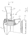
- an electric power tool according to a preferred embodiment of the present invention equipped with an adapter element inserted into a recess of the tool housing;
- Figure 2
- a battery pack adapted for insertion into the recess of the housing of the power tool of
Fig. 1 after removal of the adapter element; - Figure 3
- the power tool of
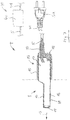
Fig. 1 in a more detailed, partially sectional view; - Figure 4
- the battery pack of
Fig. 2 in a more detailed, partially sectional view; - Figure 5
- the power tool of
Fig. 3 with a battery pack inserted into the recess of the tool housing instead of the adapter element; - Figure 6
- the housing of the power tool of
Figs. 3 and5 without an adapter element or a battery pack inserted into the recess of the tool housing; - Figure 7
- the adapter element adapted for being inserted into the recess of the housing of the power tool of
Figs. 1 ,3 and6 in a more detailed, partially sectional view; - Figure 8
- an external power supply unit for use together with the adapter element in a first view; and
- Figure 9
- the external power supply unit for use together with the adapter element in a second view.
- The present invention refers to an electrically driven hand-guided power tool 1. In the figures the power tool 1 is embodied as a polisher. However, it might just as well be embodied as a sander or any other hand-guided electric power tool. The power tool 1 comprises a
tool housing 2 with a recess 7 for receiving at least apart 9 of a battery pack 6 (seeFig. 5 ). The design of the recess 7 essentially corresponds to thepart 9 of the battery pack 6 inserted therein, in order to allow insertion of the insertedpart 9 of the battery pack 6 into the recess 7 and electric connection of the battery pack 4 with the power tool 1 and operation of the power tool 1 by means of electric energy originating from the battery pack 6. - It is suggested that the power tool 1 comprises an adapter element 4 having an
adapter housing 15 at least part 8 of which essentially corresponding to the form and design of the recess 7 and adapted to be inserted into the recess 7 after removal of the battery pack 6, in order to allow electric connection of the adapter element 4 with the power tool 1 (seeFigs. 1 and3 ). The adapter element 4 is connected to an externalpower supply unit 40 by means of a firstelectric cable 5 and thepower supply unit 40 can be connected to an electronic mains power supply by means of a secondelectric cable 41 having amains power plug 5a at its distal end. Thepower supply unit 40 comprises anelectric transformer 42 for transforming the electric energy from the mains power supply into electric energy corresponding to the electric energy supplied by the battery pack 6, in order to allow operation of the power tool 1 by means of electric energy originating from the mains power supply and transformed by thepower supply unit 40. The mains power supply voltage may be e.g. 230 V or 110 V. The voltage provided by the battery pack 6 corresponds to the operation voltage of the power tool 1, in particular of an electric motor and further electric and electronic components of the power tool 1 contained in thetool housing 2. The operation voltage may be e.g. 12 V, 18 V, 24 V, 36 V or 48 V. - According to the present invention, the
power supply unit 40 is not inserted into the recess 7 of thetool housing 2 but rather located externally. Thepower supply unit 40 is only connected to the power tool 1 by means of the adapter element 4 inserted into the recess 7 and thefirst cable 5. The adapter element 4 creates almost no heat during operation of the power tool 1. This is largely due to the fact that the adapter element 4 if at all comprises only passive electric components which create almost no heat during operation. The positioning of thepower supply unit 40 in a distance to the power tool 1 eliminates any risk of overheating of the electric and electronic components of the power tool 1 located inside thetool housing 2 due to heat from thepower supply unit 40. An efficient heat dissipation is achieved by the fact that thepower supply unit 40 can be freely located in the environment. Furthermore, the heat generated in thepower supply unit 40 may easily dissipate to the environment through respective cooling vents 43 provided in thepower supply housing 44. Thehousing 44 may be made of metal or a plastic material. - Furthermore, due to the fact that the
power supply unit 40 is provided outside of the recess 7 and does not form an integral part of the power tool 1, no re-approval of the power tool 1 is necessary if the battery pack 6 is replaced by the adapter element 4 connected to the externalpower supply unit 40. The technical approval of the power tool 1 obtained when operated with the battery pack 6 in most cases will also be valid for the power tool 1 when operated with the mains power supply through the adapter element 4 inserted into the recess 7 of thetool housing 2. - Finally, due to the fact that only the adapter element 4 is attached to the power tool 1 and that the adapter element 4 comprises not much more than the
adapter housing 15,electric terminals 14 andelectric cables 45 for connecting theterminals 14 with the firstelectric cable 5 coming from the power supply unit 40 (seeFig. 3 ), the weight of the power tool 1 is evenly distributed along the longitudinal extension of the tool 1. Preferably, the weight of the adapter element 4 (and part of the firstelectric cable 5 attached thereto and hanging down therefrom) is similar to the weight of the battery pack 6. Therefore, the power tool 1 according to the present invention can be easily used by a user over a longer period of time without signs of fatigue, no matter whether it is operated with energy from the battery pack 6 or from the mains power supply (power supply unit 40 and adapter element 4). - The adapter element 4 and the battery pack 6 are each provided with a socket element comprising the electric terminals 14 (schematically shown in
Figs. 3 ,4 ,5 and7 ), which is adapted for receiving respective contact pins 12 from the power tool 1, thepins 12 being provided at the far end of the recess 7. When the adapter element 4 or the battery pack 6 or theirrespective parts 8, 9 are completely inserted in to the recess 7, an electric connection is automatically established between the electronic components of the power tool 1 on the one hand and the adapter element 4 or the battery pack 6, respectively, on the other hand. Of course, theelectric terminals 14 and the contact pins 12 could be located at any other desired position, too, for example in a side wall of the recess 7 and of the adapter housing 15 (or the battery housing 19), respectively. - In principle the adapter element 4 is a special kind of plug element having an
adapter housing 15 designed such that it can at least partly be inserted into the recess 7. Theadapter housing 15 is provided with thecontact terminals 14 in order to establish the electric connection to the contact pins 12 of the power tool 1. The adapter element 4 establishes an electric connection between the firstelectric cable 5 and the contact pins 12 of the power tool 1 located inside the recess 7. Preferably, no electric energy is transformed by the adapter element 4 because the electric energy is transformed externally by thepower supply unit 40 and arrives at the adapter element 4 from thepower supply unit 40 through the firstelectric cable 5. Hence, no bulky and heavy transformer has to be located in the adapter element 4. - If at all, only smaller and lighter electric and electronic components which generate only a small amount of heat during operation are located in the adapter element 4 or the
adapter housing 15, respectively. For example, the adapter element 4 may comprise a rectifier for transforming an alternating voltage of the mains power supply into a direct voltage of the power tool 1 and/or an electronic filter element for reducing interferences and suppressing electronic disturbances. However, it is preferred that these electric and/or electronic components are comprised by thepower supply unit 40. To this end it is suggested that thepower supply unit 40 comprises arectifier 46 for transforming the alternating voltage of the mains power supply into a direct voltage (AD/DC-converter). Further, it is suggested that thepower supply unit 40 comprises anelectronic filter element 47 for reducing interferences and suppressing electronic disturbances. Thepower supply unit 40 may comprise a printed circuit board (PCB) 48 to which some or all of thecomponents power supply unit 40 are attached and/or electrically contacted. - Alternatively, the
power supply unit 40 may be embodied as a switched-mode power supply. Such apower supply unit 40 may be provided with a central processing unit for controlling the transformation of the electric energy. - It is suggested that the
tool housing 2 and the adapter element 4 are provided with corresponding attachment members adapted to enter into mutual engagement with each other upon complete insertion of the part 8 of the adapter element 4 to be inserted into the recess 7 and to provide for a releasable attachment of the adapter element 4 to thetool housing 2. The attachment members provide for a safe and reliable attachment of the adapter element 4 to thetool housing 2. If desired, the attachment members can be manually actuated in order to release the adapter element 4 from thetool housing 2 and to extract the adapter element 4 from the recess 7. - Preferably, the attachment members are adapted to automatically enter into mutual engagement with each other upon complete insertion of the part 8 of the adapter element 4 to be inserted into the recess 7. This has the advantage that the adapter element 4 does not have to be actively secured to the
tool housing 2 after insertion. Rather, the adapter element 4 is automatically secured to thetool housing 2 upon complete insertion. This may be effected by a snap lock or a spring lock or by a magnetic lock. - According to the embodiment of
Fig. 6 , the attachment members comprise at least one spring-loadedhook element 21 attached to thetool housing 2 within the recess 7. Of course thehook element 21 could also be attached to thetool housing 2 outside the recess 7. Alternatively, thehook element 21 could also be provided on theadapter housing 15 of the adapter element 4. The attachment members further comprise at least one corresponding recess or opening 49 provided at theadapter housing 15 of the adapter element 4 (seeFig. 7 ). The recess oropening 49 is provided in that part 8 of the adapter element 4 which is inserted into the recess 7. Of course, the recess oropening 49 could also be provided in anotherpart 10 of the adapter element 4 which is not inserted into the recess 7. Alternatively, the recess oropening 49 could also be provided in thetool housing 2 of the power tool 1. The recess oropening 49 is adapted for receiving thehook element 21 upon complete insertion of the part 8 of the adapter element 4 into the recess 7. The spring-effect of thehook element 21 may be achieved by a separate spring element (not shown) or - as is the case inFig. 6 - by means of the material of which thehook element 21 is manufactured, the material having elastic characteristics. For example, thehook element 21 could be manufactured from metal or synthetic material (e.g. plastic). - The
housing 19 of the battery pack 6 comprises a respective recess or opening 49' (seeFig. 4 ). Further, inside the battery pack 6 there are a number ofrechargeable battery cells 20. - Of course, many other embodiments of the attachment members for releasably attaching the adapter element 4 to the
tool housing 2 after complete insertion into the recess 7 are conceivable, too. - In order to provide for an appealing design of the power tool 1, it is suggested that at least that
part 10 of theadapter housing 15 which is not inserted into the recess 7 upon complete insertion of the part 8 of the adapter element 4 to be inserted into the recess 7 and still visible from outside (seeFig. 7 ) has the same design as thatpart 11 of the battery pack 6 which is not inserted into the recess 7 upon complete insertion of thepart 9 of the battery pack 6 to be inserted into the recess 7 and still visible from outside (seeFig. 5 ). Hence, the power tool 1 has almost the same look with the battery pack 6 inserted into the recess 7 or the adapter element 4 inserted therein. The only visible difference is the firstelectric cable 5 led out of theadapter housing 15 at thevisible part 10, in particular at the rear or a side of thatpart 10 of theadapter element 15 visible after complete insertion into the recess 7. - It is possible to releasably connect the
first cable 5 to the adapter element 4 by means of a plug-and-socket connection. However, in order to allow a flexible use of the power tool 1 with the adapter element 4 inserted therein without the risk of an unintentional disconnection of the power tool 1 from thepower supply unit 40, it is suggested that thefirst cable 5 is fixedly attached to the adapter element 4. The connection between the adapter element 4 and thefirst cable 5 is the one which is stressed most during an intense use of the power tool 1. Additionally, a kink protection element for thefirst cable 5 can be provided in the form of agrommet 50 attached to the adapter housing 15 (seeFig. 7 ). - Furthermore, it is suggested that the
power supply unit 40 comprises a firstelectric socket 51 for releasably attaching thefirst cable 5 to the power supply unit 40 (seeFig. 9 ). Thefirst cable 5 may be attached by means of arespective plug 52 which is connected to thefirst cable 5 and inserted into thesocket 51. Thesocket 51 and theplug 52 may have any desired form. In particular, they may have threecontacts first cable 5 for operation of the power tool 1, rather large currents (up to 10 A) will have to be transmitted across the plug-and-socket-connection first cable 5 in order to achieve the desired output power at the power tool 1. Therefore, the plug-and-socket-connection first cable 5 have to be adapted to transmit the relatively large currents. Furthermore, the firstelectric socket 51 of thepower supply unit 40 should comprise mechanical protection means in order to prevent a person from reaching thecontacts 53 of thesocket 51 with his/her fingers or an electric conductor and from getting an electric shock. Further, the plug-and-socket-connection power supply unit 40 is located in a distance to the power tool 1 and connected thereto by the flexiblefirst cable 5, there is no risk that the plug-and-socket-connection plug 52 in thesocket 51, the plug could be provided with acylindrical retaining element 55 which may be freely rotated about its longitudinal axis in respect to the rest of theplug 52. The internal surface of the retainingelement 55 is provided with a thread. Similarly, the firstelectric socket 51 is provided with a cylindrical protrudingelement 56 which has a thread on its outer surface. Upon insertion of theplug 52 into thesocket 51, the retainingelement 55 can be screwed onto the protrudingelement 56 thereby securing theplug 52 in thesocket 52. - Further, the
power supply unit 40 may comprise a secondelectric socket 57 for releasably attaching thesecond cable 41 to the power supply unit 40 (seeFig. 8 ). Thesecond cable 41 is the power cable connecting thepower supply unit 40 to the mains power supply. One end of the cable has theconventional plug 5a for connecting thecable 41 to a socket of the mains power supply. The opposite end of thesecond cable 41 is provided with anotherplug 58 adapted for connection to thesecond socket 57 of thepower supply unit 40. As shown inFig. 8 , thesecond socket 57 may be embodied as a conventional 3-pole AC current input module. In that case, thesecond cable 41 could be a conventional power cable comprising a mainspower supply plug 5a on one end and the 3-pole AC current plug 58 for connection to the 3-pole ACcurrent input module 57 on the other end.
Claims (12)
- Electrically driven hand-guided power tool (1), in particular a polisher or a sander, comprising a tool housing (2) with a recess (7) for receiving at least a part (9) of a battery pack (6), the design of the recess (7) corresponding to the part (9) of the battery pack (6) inserted therein, in order to allow insertion of the part (9) of the battery pack (6) into the recess (7) and electric connection of the battery pack (6) with the power tool (1) and operation of the power tool (1) by means of electric energy originating from the battery pack (6),
characterized in that
the power tool (1) comprises an adapter element (4) having an adapter housing (15) at least part (8) of which corresponding to the form and design of the recess (7) and adapted to be inserted into the recess (7) after removal of the battery pack (6), in order to allow electric connection of the adapter element (4) with the power tool (1), the adapter element (4) being connected to an external power supply unit (40) by means of a first electric cable (5) and the power supply unit (40) being connectable to an electronic mains power supply by means of a second electric cable (41), the power supply unit (40) comprising an electric transformer (42) for transforming the electric energy from the mains power supply into electric energy corresponding to the electric energy supplied by the battery pack (6), in order to allow operation of the power tool (1) by means of electric energy originating from the mains power supply and transformed by the power supply unit (40). - Power tool (1) according to claim 1, wherein
the electric transformer (42) of the external power supply unit (40) is adapted to transform a voltage of 230 V or 110 V, respectively, of the mains power supply into an operating voltage of 12 V, 18 V, 24 V, 36 V or 48 V, respectively, of the power tool (1). - Power tool (1) according to claim 1 or 2, wherein
the power supply unit (40) comprises a rectifier (46) for transforming an alternating voltage of the mains power supply into a direct voltage for the power tool (1). - Power tool (1) according to one of the preceding claims, wherein
the power supply unit (40) comprises an electronic filter element (47) for reducing interferences and suppressing electronic disturbances. - Power tool (1) according to one of the preceding claims, wherein
the tool housing (2) and the adapter housing (15) are provided with corresponding attachment members (21, 49) adapted to enter into mutual engagement with each other upon complete insertion of the part (8) of the adapter element (4) to be inserted into the recess (7) and to provide for a releasable attachment of the adapter element (4) to the tool housing (2). - Power tool (1) according to claim 5, wherein
the attachment members (21, 49) are adapted to automatically enter into mutual engagement with each other upon complete insertion of the part (8) of the adapter element (4) to be inserted into the recess (7). - Power tool (1) according to claim 5 or 6, wherein
the attachment members (21, 49) comprise at least one spring-loaded hook element (21) attached to one of the tool housing (2) and the adapter housing (15) and at least one corresponding recess or opening (49) attached to the other one of the tool housing (2) and the adapter housing (15), for receiving the hook element (21) upon complete insertion of the part (8) of the adapter element (4) to be inserted into the recess (7). - Power tool (1) according to one of the preceding claims, wherein
at least that part (10) of the adapter housing (15) which is not inserted into the recess (7) upon complete insertion of the part (8) of the adapter element (4) to be inserted into the recess (7) and still visible from outside has the same design as that part (11) of the battery pack (6) which is not inserted into the recess (7) upon complete insertion of the part (9) of the battery pack (6) to be inserted into the recess (7) and still visible from outside. - Power tool (1) according to one of the preceding claims, wherein
the power supply unit (40) is adapted to comply with the ATEX 95 equipment directive 94/9/EC. - Power tool (1) according to one of the preceding claims, wherein
the first cable (5) is fixedly attached to the adapter unit (4). - Power tool (1) according to one of the preceding claims, wherein
the power supply unit (40) comprises a first electric socket (51) for releasably attaching the first cable (5) to the power supply unit (40). - Power tool (1) according to one of the preceding claims, wherein
the power supply unit (40) comprises a second electric socket (57) for releasably attaching the second cable (41) to the power supply unit (40).
Priority Applications (1)
| Application Number | Priority Date | Filing Date | Title |
|---|---|---|---|
| EP19200836.5A EP3800012A1 (en) | 2019-10-01 | 2019-10-01 | Electrically driven hand-guided power tool |
Applications Claiming Priority (1)
| Application Number | Priority Date | Filing Date | Title |
|---|---|---|---|
| EP19200836.5A EP3800012A1 (en) | 2019-10-01 | 2019-10-01 | Electrically driven hand-guided power tool |
Publications (1)
| Publication Number | Publication Date |
|---|---|
| EP3800012A1 true EP3800012A1 (en) | 2021-04-07 |
Family
ID=68109229
Family Applications (1)
| Application Number | Title | Priority Date | Filing Date |
|---|---|---|---|
| EP19200836.5A Withdrawn EP3800012A1 (en) | 2019-10-01 | 2019-10-01 | Electrically driven hand-guided power tool |
Country Status (1)
| Country | Link |
|---|---|
| EP (1) | EP3800012A1 (en) |
Cited By (1)
| Publication number | Priority date | Publication date | Assignee | Title |
|---|---|---|---|---|
| DE102022206132A1 (en) | 2022-06-20 | 2023-12-21 | Robert Bosch Gesellschaft mit beschränkter Haftung | Electrical processing device and system comprising an electrical processing device and an external power supply device |
Citations (11)
| Publication number | Priority date | Publication date | Assignee | Title |
|---|---|---|---|---|
| EP0291131A1 (en) * | 1987-05-15 | 1988-11-17 | Emerson Electric Co. | Tool for intermediate voltage |
| US6243276B1 (en) * | 1999-05-07 | 2001-06-05 | S-B Power Tool Company | Power supply system for battery operated devices |
| US20020175654A1 (en) * | 2001-05-25 | 2002-11-28 | Hitachi Koki Co., Ltd. | DC power source unit with battery charging function |
| EP1469583A2 (en) * | 2003-04-16 | 2004-10-20 | David Bech | Switch mode power converter, charger device and portable electrical tool |
| JP2005278375A (en) * | 2004-03-26 | 2005-10-06 | Hitachi Koki Co Ltd | Dc power supply unit and adapter used for dc power supply unit |
| WO2009100673A1 (en) * | 2008-02-03 | 2009-08-20 | Weiliang Jiang | A portable electric tool, cordless tool, gardening tool, carpenter's tool |
| US20130293197A1 (en) * | 2007-09-13 | 2013-11-07 | Kazuyuki Sakakibara | Battery pack |
| EP2712713A1 (en) | 2012-10-01 | 2014-04-02 | Guido Valentini | Electronically driven mobile equipment comprising a battery pack and electronic power supply unit for use with such a mobile equipment |
| GB2519563A (en) * | 2013-10-24 | 2015-04-29 | John Carl Henry | Adaptor for battery powered tool |
| US20150194646A1 (en) * | 2012-07-06 | 2015-07-09 | Hitachi Koki Co., Ltd. | Backpack-Type Power Supply |
| GB2534413A (en) * | 2015-01-23 | 2016-07-27 | Loan Chira Daniel | Power adaptor for cordless tools |
-
2019
- 2019-10-01 EP EP19200836.5A patent/EP3800012A1/en not_active Withdrawn
Patent Citations (11)
| Publication number | Priority date | Publication date | Assignee | Title |
|---|---|---|---|---|
| EP0291131A1 (en) * | 1987-05-15 | 1988-11-17 | Emerson Electric Co. | Tool for intermediate voltage |
| US6243276B1 (en) * | 1999-05-07 | 2001-06-05 | S-B Power Tool Company | Power supply system for battery operated devices |
| US20020175654A1 (en) * | 2001-05-25 | 2002-11-28 | Hitachi Koki Co., Ltd. | DC power source unit with battery charging function |
| EP1469583A2 (en) * | 2003-04-16 | 2004-10-20 | David Bech | Switch mode power converter, charger device and portable electrical tool |
| JP2005278375A (en) * | 2004-03-26 | 2005-10-06 | Hitachi Koki Co Ltd | Dc power supply unit and adapter used for dc power supply unit |
| US20130293197A1 (en) * | 2007-09-13 | 2013-11-07 | Kazuyuki Sakakibara | Battery pack |
| WO2009100673A1 (en) * | 2008-02-03 | 2009-08-20 | Weiliang Jiang | A portable electric tool, cordless tool, gardening tool, carpenter's tool |
| US20150194646A1 (en) * | 2012-07-06 | 2015-07-09 | Hitachi Koki Co., Ltd. | Backpack-Type Power Supply |
| EP2712713A1 (en) | 2012-10-01 | 2014-04-02 | Guido Valentini | Electronically driven mobile equipment comprising a battery pack and electronic power supply unit for use with such a mobile equipment |
| GB2519563A (en) * | 2013-10-24 | 2015-04-29 | John Carl Henry | Adaptor for battery powered tool |
| GB2534413A (en) * | 2015-01-23 | 2016-07-27 | Loan Chira Daniel | Power adaptor for cordless tools |
Cited By (1)
| Publication number | Priority date | Publication date | Assignee | Title |
|---|---|---|---|---|
| DE102022206132A1 (en) | 2022-06-20 | 2023-12-21 | Robert Bosch Gesellschaft mit beschränkter Haftung | Electrical processing device and system comprising an electrical processing device and an external power supply device |
Similar Documents
| Publication | Publication Date | Title |
|---|---|---|
| CN108270264B (en) | Portable tower with electrical outlets | |
| US7990102B2 (en) | Cordless power supply | |
| US8072183B2 (en) | Multiple interface device charger with removable battery pack | |
| US8994330B2 (en) | Outlet assembly with portable charger | |
| US11916411B2 (en) | Modular charging system and wall-mounted charging device and modular power devices | |
| KR101615430B1 (en) | Vacuum cleaner | |
| US20110286168A1 (en) | Cordless power supply | |
| US10367367B1 (en) | Electronic watch recharging device | |
| US6160728A (en) | Dual-mode AC/DC electrical receptacle | |
| US10862176B2 (en) | Portable rechargeable battery pack with a selectable battery switch and state of charge display for cordless power tools | |
| JP6373688B2 (en) | Lighting device | |
| US20130334898A1 (en) | Ac power systems for powering cordless power tools | |
| CN107579583B (en) | Multifunctional portable power supply charger | |
| EP3800012A1 (en) | Electrically driven hand-guided power tool | |
| US20180102666A1 (en) | Battery inductive charging device | |
| WO2006012701A1 (en) | Rechargeable flashlight | |
| WO2011097465A1 (en) | Apparatus and method for providing power from a power source to a portable electrical device | |
| TW382155B (en) | Portable apparatus for recharging batteries in drills, screwers, portable electric tools generally fed by internal batteries | |
| CN112996631B (en) | Long rod type sander | |
| US20140370743A1 (en) | External Power Supply | |
| US20090097250A1 (en) | Integrated battery charging work light electrical distribution system | |
| US9071022B2 (en) | Power plug having a universal serial bus port for an electrical appliance | |
| US10381848B2 (en) | Power device with multiple electrifying modes | |
| CN218005978U (en) | Electronic equipment of cutting a pencil and electronic host computer of cutting a pencil based on wireless charging | |
| EP3981310A1 (en) | Electrically operated mobile vacuum cleaner |
Legal Events
| Date | Code | Title | Description |
|---|---|---|---|
| PUAI | Public reference made under article 153(3) epc to a published international application that has entered the european phase |
Free format text: ORIGINAL CODE: 0009012 |
|
| STAA | Information on the status of an ep patent application or granted ep patent |
Free format text: STATUS: THE APPLICATION HAS BEEN PUBLISHED |
|
| AK | Designated contracting states |
Kind code of ref document: A1 Designated state(s): AL AT BE BG CH CY CZ DE DK EE ES FI FR GB GR HR HU IE IS IT LI LT LU LV MC MK MT NL NO PL PT RO RS SE SI SK SM TR |
|
| AX | Request for extension of the european patent |
Extension state: BA ME |
|
| STAA | Information on the status of an ep patent application or granted ep patent |
Free format text: STATUS: THE APPLICATION IS DEEMED TO BE WITHDRAWN |
|
| 18D | Application deemed to be withdrawn |
Effective date: 20211008 |