EP3799995A1 - Chalumeau de soudage à l'arc - Google Patents
Chalumeau de soudage à l'arc Download PDFInfo
- Publication number
- EP3799995A1 EP3799995A1 EP19000447.3A EP19000447A EP3799995A1 EP 3799995 A1 EP3799995 A1 EP 3799995A1 EP 19000447 A EP19000447 A EP 19000447A EP 3799995 A1 EP3799995 A1 EP 3799995A1
- Authority
- EP
- European Patent Office
- Prior art keywords
- welding torch
- arc welding
- torch device
- guide element
- wire core
- Prior art date
- Legal status (The legal status is an assumption and is not a legal conclusion. Google has not performed a legal analysis and makes no representation as to the accuracy of the status listed.)
- Pending
Links
- 238000003466 welding Methods 0.000 title claims abstract description 416
- 238000000034 method Methods 0.000 claims abstract description 34
- 230000008569 process Effects 0.000 claims abstract description 34
- 230000011664 signaling Effects 0.000 claims abstract description 18
- 238000003780 insertion Methods 0.000 claims abstract description 10
- 230000037431 insertion Effects 0.000 claims abstract description 10
- 239000000155 melt Substances 0.000 claims abstract description 7
- 238000007789 sealing Methods 0.000 claims description 15
- 239000000463 material Substances 0.000 claims description 8
- 230000005540 biological transmission Effects 0.000 claims description 5
- 230000003287 optical effect Effects 0.000 claims description 2
- 239000000919 ceramic Substances 0.000 claims 1
- 239000012811 non-conductive material Substances 0.000 claims 1
- 239000007789 gas Substances 0.000 description 27
- 230000001681 protective effect Effects 0.000 description 12
- 239000002184 metal Substances 0.000 description 10
- 229910052751 metal Inorganic materials 0.000 description 10
- 241000446313 Lamella Species 0.000 description 7
- 230000006835 compression Effects 0.000 description 7
- 238000007906 compression Methods 0.000 description 7
- 230000008901 benefit Effects 0.000 description 5
- 229910001369 Brass Inorganic materials 0.000 description 4
- 239000010951 brass Substances 0.000 description 4
- 230000008859 change Effects 0.000 description 4
- 230000002093 peripheral effect Effects 0.000 description 3
- 230000007704 transition Effects 0.000 description 3
- 230000009471 action Effects 0.000 description 2
- 239000004020 conductor Substances 0.000 description 2
- 238000009422 external insulation Methods 0.000 description 2
- 239000011261 inert gas Substances 0.000 description 2
- 239000000565 sealant Substances 0.000 description 2
- RYGMFSIKBFXOCR-UHFFFAOYSA-N Copper Chemical compound [Cu] RYGMFSIKBFXOCR-UHFFFAOYSA-N 0.000 description 1
- 229910000881 Cu alloy Inorganic materials 0.000 description 1
- 230000006978 adaptation Effects 0.000 description 1
- 230000000712 assembly Effects 0.000 description 1
- 238000000429 assembly Methods 0.000 description 1
- 230000015572 biosynthetic process Effects 0.000 description 1
- 238000006243 chemical reaction Methods 0.000 description 1
- 229910052802 copper Inorganic materials 0.000 description 1
- 239000010949 copper Substances 0.000 description 1
- 230000008878 coupling Effects 0.000 description 1
- 238000010168 coupling process Methods 0.000 description 1
- 238000005859 coupling reaction Methods 0.000 description 1
- 238000005553 drilling Methods 0.000 description 1
- 230000000694 effects Effects 0.000 description 1
- 238000010891 electric arc Methods 0.000 description 1
- 230000002349 favourable effect Effects 0.000 description 1
- 239000000945 filler Substances 0.000 description 1
- 238000009434 installation Methods 0.000 description 1
- 238000009413 insulation Methods 0.000 description 1
- 239000012212 insulator Substances 0.000 description 1
- 238000002844 melting Methods 0.000 description 1
- 230000008018 melting Effects 0.000 description 1
- 238000004021 metal welding Methods 0.000 description 1
- 239000000203 mixture Substances 0.000 description 1
- 230000003647 oxidation Effects 0.000 description 1
- 238000007254 oxidation reaction Methods 0.000 description 1
- 125000006850 spacer group Chemical group 0.000 description 1
- 239000000126 substance Substances 0.000 description 1
- 230000001960 triggered effect Effects 0.000 description 1
- 230000000007 visual effect Effects 0.000 description 1
Images


Classifications
-
- B—PERFORMING OPERATIONS; TRANSPORTING
- B23—MACHINE TOOLS; METAL-WORKING NOT OTHERWISE PROVIDED FOR
- B23K—SOLDERING OR UNSOLDERING; WELDING; CLADDING OR PLATING BY SOLDERING OR WELDING; CUTTING BY APPLYING HEAT LOCALLY, e.g. FLAME CUTTING; WORKING BY LASER BEAM
- B23K9/00—Arc welding or cutting
- B23K9/12—Automatic feeding or moving of electrodes or work for spot or seam welding or cutting
- B23K9/122—Devices for guiding electrodes, e.g. guide tubes
-
- B—PERFORMING OPERATIONS; TRANSPORTING
- B23—MACHINE TOOLS; METAL-WORKING NOT OTHERWISE PROVIDED FOR
- B23K—SOLDERING OR UNSOLDERING; WELDING; CLADDING OR PLATING BY SOLDERING OR WELDING; CUTTING BY APPLYING HEAT LOCALLY, e.g. FLAME CUTTING; WORKING BY LASER BEAM
- B23K9/00—Arc welding or cutting
- B23K9/12—Automatic feeding or moving of electrodes or work for spot or seam welding or cutting
- B23K9/133—Means for feeding electrodes, e.g. drums, rolls, motors
- B23K9/1336—Driving means
-
- B—PERFORMING OPERATIONS; TRANSPORTING
- B23—MACHINE TOOLS; METAL-WORKING NOT OTHERWISE PROVIDED FOR
- B23K—SOLDERING OR UNSOLDERING; WELDING; CLADDING OR PLATING BY SOLDERING OR WELDING; CUTTING BY APPLYING HEAT LOCALLY, e.g. FLAME CUTTING; WORKING BY LASER BEAM
- B23K9/00—Arc welding or cutting
- B23K9/24—Features related to electrodes
- B23K9/26—Accessories for electrodes, e.g. ignition tips
Definitions
- the invention relates to an arc welding torch device with a consumable electrode, the electrode being provided with a direction of movement from a rear end of the arc welding torch device to advance in the direction of a front end of the arc welding torch device, in the area of which the electrode melts during an arc welding process, the electrode in the arc welding torch device in an exchangeable wire core, the wire core in turn being arranged at least in the area of the rear end of the arc welding torch device in a guide element surrounding the wire core and designed as an exchangeable wear part, and the guide element of the wire core being provided for joint wear-related replacement with the wire core.
- Such an arc welding torch device can preferably also be provided with a media feed for a protective or active gas and for electrical current.
- the present invention has particular relevance to arc welding. This is based on the heat generated by an electric arc between a welding electrode and a workpiece on which welding is to be carried out. Due to the heat development, the material or materials to be welded can be melted locally.
- a protective gas is supplied to the area of the arc, on the one hand to enable a resistance-reducing ionized atmosphere between the welding electrode and the workpiece and, on the other hand, to prevent oxidation of the welding electrode and the workpiece.
- an active gas or a mixed form can also be supplied, which is used for the reaction.
- Electrodes can also be provided which do not require an external gas supply, since they are used for this The necessary substances are integrated in the electrodes and are released when the electrodes melt.
- An arc welding torch is usually designed in such a way that a user or a robot can point a metal welding wire, which can also be referred to as a metal filler material, at a specified joint on the target metal piece.
- the welding wire is passed through the welding torch and finally transported to the target metal piece through an opening in the contact nozzle at the process-side end of the welding torch.
- a high electrical current flows from a welding torch inner tube via a so-called nozzle holder, then over the contact nozzle, over the welding wire and, if necessary, an arc to the target metal piece and then to the ground.
- the high current and the arc cause the welding wire to melt in a protective gas atmosphere, which leads to the formation of droplets in the wire and the creation of an arc.
- the drops of the welding wire fall off or when the drops are transferred in a short circuit to the liquefied point of the target metal pieces, they are connected to one another. Due to the small distance from the contact nozzle and the gas nozzle to the arc or the heated target metal piece, these components are very heated. Due to the high thermal load, the contact nozzle in particular is exposed to heavy wear.
- Conventional torch systems consist in their front end section on the welding process side, as a rule, essentially of the contact nozzle, the nozzle holder and the outer gas nozzle. These components are usually detachably mounted on the torch neck (outer tube, inner tube) and thermally or electrically via contact surfaces, threads with one another or with other components of the torch neck coupled or isolated.
- the outer tube must be electrically decoupled from other live components, since no voltage may be applied there for safety reasons.
- the thermal coupling of the components attempts to dissipate the energy, which is introduced into the contact nozzle or gas nozzle in the form of heat, via the outer tube or inner tube as effectively as possible and thereby lower the maximum temperature of the contact nozzle in order to minimize wear.
- the welding wire functioning as a consumable electrode and the shielding gas are usually supplied to the arc welding torch device in the region of their rear end, provided the respective welding process provides for such a gas.
- the welding wire is advanced through the interior of the arc welding torch device from its rear end to the exit from the front, process-side end according to the consumption.
- wire feed means known per se are arranged in the region of the rear end, which feed the welding wire for example by means of a driven pair of wheels and move it through the interior of the arc welding torch device.
- the welding wire is usually arranged in a so-called wire core.
- the wear in the interior of the arc welding torch device due to the feed movement of the welding wire thus takes place primarily in the wire core and not on components of the housing of the arc welding torch device. The latter thus wears out instead of other components inside the arc welding torch device. As a result, it is necessary that the wire core is replaced from time to time.
- a disadvantage of this solution is that, in particular, the assembly of the wire core in the area of the rear end of the arc welding torch device has to be done blindly and it is therefore not possible to check whether the newly introduced components are correctly arranged and assembled.
- a faulty assembly becomes apparent only after the arc welding torch device has been started up again if, due to the faulty assembly of the arc welding torch device, it does not work as intended and / or expensive scrap is produced with it.
- a time-consuming and costly renewed dismantling and reassembly of the arc welding torch device and a temporary shutdown of a welding system associated with high investment costs must then take place.
- the invention is therefore based on the object of creating a way of being able to better control and assess correct assembly of a replaced wire core in an arc welding torch device of the type mentioned at the beginning.
- this object is achieved according to the invention in that for the guide element with regard to its direction of insertion into the arc welding torch, a predetermined end position is provided in the arc welding torch, when it is reached by the guide element, a position signaling means signals the correct position of the guide element.
- the position signaling means signals the correct position by means of a signal that can be perceived outside or from the outside of the arc welding torch device. It is particularly preferred here if the position signaling means is designed as a position indicating means which is arranged outside the arc welding torch device and which can be perceived from the outside as an optical signal when the target position of the guide element is reached.
- the position signaling means as a visually perceptible position indicating means are also conceivable.
- an electrical signal could be triggered or interrupted by correctly positioning the guide element, which receives the wire core and is introduced into the arc welding device together with it, which is then made perceptible to an operator using suitable means.
- an acoustic signal or a signal that is optically perceptible on a display means could be generated.
- the guide element is guided with one of its ends through an outer, end-side housing part of the arc welding torch device, in particular together with the welding wire, and in this case, in the position of use of the guide element in the arc welding torch device, out of the outer housing part the arc welding torch device protrudes to the outside.
- the outer housing part can in particular be an end cap of the arc welding torch device, which is connected to a jacket tube extending over the longitudinal axis of the arc welding torch device.
- the guide element as a sleeve with - in relation on its longitudinal extent along its longitudinal axis - different sized diameters of its outer surface is formed. This makes it possible to use at least one section of the guide means for precise positioning according to a predetermined target position along the longitudinal axis of the arc welding torch device and another section of the guide means as position indicator means protruding from the housing of the arc welding torch device.
- the at least one section of the guide means with the larger diameter can bear against a stop in the interior of the arc welding torch device when it is in the desired position. Such a predetermined position of the guide means can then be signaled in a visually perceptible manner by the at least one section of the guide means with a smaller diameter outside the housing of the arc welding torch device. This section can thus take over the function of the position display means.
- the section with the smaller outer diameter in particular with the smallest outer diameter, is located in front of the at least one section with one or more larger outer diameters of the guide means.
- a sleeve-shaped inlet body can be provided which is connected, in particular detachably connected, to the housing of the arc welding body.
- the housing can in particular be a casing tube that also has the outer surface of the casing of the arc welding torch device and / or an end cap attached to the casing tube at the end.
- the sleeve-shaped inlet body can with a extending in the direction of the longitudinal axis be provided cylindrical recess.
- the cylindrical recess can preferably have a constant diameter, which serves as a receptacle for the guide body, in which the guide body is preferably arranged without connection.
- the sleeve-shaped inlet body can be connected to the housing of the arc welding torch device, in particular it can be detachably connected, for example by means of a threaded connection.
- the inlet body can preferably be connected to an end component of the housing, for example an end cap.
- a through recess of the end component of the housing can be provided with a shoulder so that a position stop is formed for the inlet body in the direction of insertion of the exchangeable components, wire core and guide body.
- the through recess of the end-side component can preferably taper conically, wherein the conical section can advantageously be provided as a push-in delimitation of the guide element.
- both the guide element against the end cap and the guide element against the sleeve-shaped inlet body are sealed with a sealant in order to avoid leakage of the protective gas supplied to the welding process point inside the arc welding torch device.
- one of the sealing means can preferably be arranged on the outer jacket surface between two sections of the guide body with different diameters.
- the section with the smaller diameter can be the section of the guide element, the end of which protrudes from the end cap when it is correctly positioned.
- the other section with the larger diameter can preferably be that section of the guide element with which the guide element is arranged in the inlet body, preferably without connection, but nevertheless with as little play as possible.
- This first sealing element is particularly preferably arranged on a conical section between the two sections with a larger and a smaller diameter and also rests against the through hole of the end cap, preferably in the area of a conical section of the Through hole.
- the sealing element does not generate any relevant holding forces between the guide element and the inlet body, which means that the guide element together with the wire core can be released from the arc welding torch device in a particularly simple manner and without releasing holding or connecting forces.
- the second sealing element is preferably arranged on a section of the outer circumferential surface of the guide element with a larger diameter.
- This section is preferably designed with a larger diameter than a section with a constant diameter and is located within the cylindrical recess of the inlet body.
- the guide element is held non-positively or positively in the inlet body. This makes it possible to achieve additional security that the guide element remains correctly positioned not only when it is inserted into the arc welding torch device but also during its operation.
- a solution can also be advantageous in which the guide element receiving one of the ends of the wire core is arranged in its end position - even during use of the arc welding torch device - without a holding force within the arc welding torch device.
- the position signaling means preferably continuously signals this not only during the insertion process but also during operation, but at least if necessary, with a correctly positioned arrangement, it is also possible to do without a holding force. If a deviation of the guide element from its intended position is determined on the basis of the position signaling means, appropriate action can then be taken.
- This solution also has the advantage that, due to the lack of holding force, the assembly comprising the wire core and the guide element is at least essentially easy overall from the arc welding device of at least substantially without overcoming a holding force at the front, in the area of the process point, can be pulled out of the arc welding torch device without having to dismantle the arc welding torch device itself, in particular at its rear end.
- the aspect of the invention relating to the interchangeable assembly is based on the idea of being able to ensure a position-correct arrangement of the interchangeable assembly introduced from the front, from the welding process-side end of the arc welding torch device, so that reaching or not reaching the intended position of the blind and common inserted wire core and guide body can be checked from the outside, in particular visually checked. Since the arrangement has to be made in the non-visible interior of the arc welding torch device, an externally perceptible position signaling means, in particular a visually perceptible position indicating means, is an enormous help in avoiding incorrect positioning of the wire core and the at least one guide element of the replaceable assembly inserted from the front. It is preferred here that the position signaling means, in particular position indicating means, signal to the exchangeable assembly a correct actual arrangement in the desired position inside the housing only when the guide means belonging to the wire core and the common exchangeable assembly are in place Has actually reached the end position.
- a concrete solution that is technically particularly easy to implement can provide that the position signaling means, in particular position indicating means, is part of the guide element or another component of the replaceable component group, which is built into the respective arc welding torch device as a result of wear and in exchange for a component group of a worn wire core.
- This position signaling means, in particular position indicating means should therefore together with the assembly at the process-side end are introduced into the arc welding torch device and passed completely through the arc welding torch device to its rear end through the arc welding torch device.
- the position signaling means, in particular position indicating means, of the replaceable assembly should emerge again from the housing of the arc welding torch device in the area of the rear end facing away from the process-side end and thus be visually perceptible from the outside.
- the risk of the welding wire kinking due to its feed movement and due to the entry into a narrow recess of the arc welding torch device provided on the end face is to be reduced.
- this object can be achieved according to the invention by an anti-kink means for the welding wire in which the welding wire is guided protruding from the arc welding torch device and arranged between an outer end cap of the arc welding torch device and wire feed means, as described in particular in claim 17 .
- a preferred further development of an embodiment of this aspect of the invention can provide that the anti-kink means is detachably arranged in the arc welding torch device and a portion of the anti-kink means protrudes from a recess in the end cap of the arc welding torch device. This makes it particularly easy to provide the anti-kink means as a replaceable wear part. Since the anti-kink means is arranged in the interior of the housing of the arc welding torch device, it can preferably be designed as part of the assembly, which is replaced as a whole with a new assembly of this type when the wire core is worn.
- the kink protection means is sleeve-shaped and with a continuous recess for receiving the welding wire, and preferably in the wire feed end with a boundary wall of the continuous recess is provided with a bevel.
- the recess here preferably runs concentrically to the intended course of the longitudinal axis of the welding wire. It can also be favorable that a diameter of the recess is matched to the diameter of the welding wire in such a way that the welding wire is safely guided in the recess and nevertheless experiences as little resistance as possible when moving through the recess.
- the bevel can support a safe and kink-free entry of the welding wire into the anti-kink means.
- the present invention can be particularly advantageous in connection with automated welding processes in which an arc welding torch is guided and moved by a welding robot.
- the problem here is that in order to replace a worn wire core, it is possible that not only the arc welding torch device itself has to be completely or partially dismantled.
- the arc welding torch device itself may also have to be removed from the robot so that there is access to the wire core and an exchange of the wire core is made possible.
- the more extensive a dismantling has to take place the more extensive and time-consuming the subsequent assembly will be. Due to the dismantling, there may even be another time-consuming teach-in of the welding robot with the arc welding torch device attached.
- the exchange of wire cores according to the invention from the welding process side, together with the position signaling means according to the invention, can therefore have particular advantages. This means that the wire core can be replaced quickly and without extensive Dismantling work and nevertheless a correct position of the new wire core inside the arc welding torch device.
- this advantage can be particularly pronounced when a hollow-shaft robot, such as one of the "Motoman" type, which is offered as a welding robot by the manufacturer Yaskawa Europe GmbH, 65760 Eschborn, Germany, is used as the robot.
- the welding media such as welding wire, shielding gas and electric current
- the arc welding torch device is carried out essentially or at least approximately concentrically to the axis of rotation of the hollow shaft through the receptacle designed as a rotationally driven hollow shaft for attaching the arc welding torch device to the robot.
- a dismantling of the arc welding torch device itself and of the mounting of the robot is particularly labor-intensive here.
- Such a hollow-shaft robot and a particularly advantageous solution for an arc welding torch device that interacts with this hollow-shaft robot is shown, for example, in FIG EP 1 689 550 B1 described. Their disclosure content is hereby fully incorporated by reference.
- An arc welding torch which is intended for arrangement on a welding robot which has a robot arm, can therefore have a connection device which can be rotated relative to the robot arm and which has a fastening device for attaching the welding torch device to the welding robot, a receiving device for holding a welding torch and for transmitting driven rotary movements on the welding torch, an electrical connection for a welding current cable, by means of which a robot side of the welding torch device can be electrically connected to a welding power source, and a current transmission device via which the welding current cable can be electrically connected to a welding torch side of the welding torch device.
- the power transmission device can have a stator which is provided for a non-rotatable arrangement opposite the robot arm, but in relation to the connection device on the welding robot side is relatively rotatable. Furthermore, a lead-through of the stator through which at least one of the consumables required for the welding process can be carried out in the direction of the receiving device can be provided, the receiving device and the fastening device being designed as a rotor, which are thereby rotatable relative to the stator, and the receiving device and / or the fastening device can be connected to the stator in an electrically conductive manner by means of an electrical contact device, the fastening device of the rotor being designed for attachment to the connection device of the robot, and by being attached to the connection device of the robot, an axis of rotation of the rotor with the axis of rotation of the connection device of the Robot is at least substantially aligned and the rotor is rotatable about the axis of rotation and the stator.
- a recess is provided which runs along the axis of rotation of the rotor and runs centrally (in alignment) with respect to the axis of rotation both through the fastening device and through the receiving device, with both an inlet opening of the recess in the stator as an exit opening of the recess in the rotor are also arranged centrally and thus in alignment with respect to the axis of rotation.
- the entry opening in the arc welding torch for welding media coming from the welding cable is thus located along the axis of rotation of the arc welding torch.
- the exit opening for the exit of welding media from the rotor and their passage into the welding torch neck is also located in alignment with the axis of rotation of the rotor.
- the entire recess thus preferably runs along the axis of rotation of the rotor and thus also the robot-side connection device with which rotational movements of the rotor around the stator are generated and transmitted from the robot to the rotor.
- the welding wire can thus be inserted into the arc welding torch device at the end on the wire feed side and through the wire core to the process-side end of the arc welding torch device. While the arc welding torch device is in use, the welding wire is pushed in due to the welding wire tip melting off in the process area. The welding wire is thereby moved longitudinally through the entire arc welding torch device and thus also through the connecting flange of the hollow shaft robot for the arc welding torch and through its stator.
- the arc welding torch device To replace the wire core and its assembly, the arc welding torch device must preferably only be slightly dismantled in the area of its process-side end, so that there is access to the process-side end of the wire core, which can then be completely pulled out by hand from the arc welding torch device and its process-side end.
- the arc welding torch device remains unchanged on the connection flange of the hollow shaft robot and the worn and the new wire core and the respective associated assemblies, preferably including the position signaling means and / or preferably the anti-kink means, are moved inside the arc welding torch device and thus through the robot-side connection flange.
- the exchange of the wire core can therefore be carried out extremely quickly and reliably with little effort, even in the case of a hollow-shaft robot.
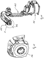
- a preferred embodiment of an arc welding torch device 1 according to the invention is shown.
- the arc welding torch device 1 is intended for use in an automatic welding machine, such as a welding robot not shown in detail.
- the arc welding torch device 1 is arranged on an end manipulator of the robot, not shown in detail, which can be moved in different spatial directions, preferably in all spatial directions on any desired feed paths.
- the end manipulator can thereby carry the arc welding torch 1 along its feed path and the arc welding torch 1 can perform weld seams on workpieces.
- the arc welding torch can in principle be designed in the same way as that in FIG WO 2005/049259 A1 disclosed and described arc welding torch, with differences in the end region of the arc welding torch from Fig.
- the arc welding torch 1 Due to the not absolutely necessary, but particularly preferred embodiment of the arc welding torch 1, according to which it has an external stator part and an internal rotor part and a feed and supply of the welding point with welding media at least essentially along and coaxially to a longitudinal axis 3 of rotation of the arc welding torch device and the End manipulator takes place, the possibility of endless rotation of the welding torch can be achieved and twisting of a welding cable during rotational movements can be avoided.
- arc welding torch shown and discussed here is only given as an example of the invention and the invention can in principle also be used in connection with other types of arc welding torches and in particular also with arc welding torch devices, the specific structure of which depends on the structure of the Arc welding torch device discussed below differs.
- the arc welding torch device 1 shown only as an example for the invention is a welding torch 1 that operates according to the metal shielding gas welding process
- Welding wire 7 which melts off during the welding process is fed to the intended welding point and is continuously tracked due to the consumption of welding wire 7 during a welding process.
- the welding wire 7 is here as a rule fed through the interior of the welding torch 1, mostly through a jacket tube 2, together with its wire core 8a and preferably an insulation surrounding the welding wire.
- a protective gas is supplied to the welding point, usually also through the jacket tube 2.
- the protective gas is an inert gas; in other exemplary embodiments according to the invention, an active gas - or a mixture of both - can also be supplied as protective gas.
- both the welding wire and the shielding gas and the current can be fed to the arc welding torch at its power connection point via a welding cable known per se, in particular a coaxial welding cable.
- the shielding gas is introduced into a passage 9 of the welding torch 1 in its interior for the implementation of the shielding gas from the connection point to the free end of the welding point.
- the current is also conducted from the welding cable through the welding torch 1 to the welding or process point.
- the current is also conducted inside the welding torch to the process point in such a way that an outside of the arc welding torch device 1 is current-free.
- the arc welding torch device 1 thus has a torch neck 4 which is connected to a hose package 2.
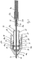
- the hose package 2 runs approximately from rear end 6 of the arc welding torch device 1 up to the welding torch at the front end 5 on the welding process side Fig. 2 is shown, a plurality of replaceable wear parts are arranged in the interior of the arc welding torch 1, which will be discussed in more detail below.
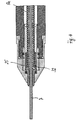
- Fig. 2 the rear end 6 of the arc welding torch device 1 facing away from the welding process point and the associated front open end 5 of the arc welding torch device 1 together with two drive rollers 10, 11 of a wire feed device 12 is shown in a detail view.
- the welding wire 7 is shown between the two drive rollers 10, 11 opposite one another with their peripheral surfaces.
- the drive rollers 10, 11 are located directly opposite the rear end 6 of the arc welding torch device 1 facing away from the process point of the arc welding torch 1 through hole 16 open towards the outer end of the end cap 14 ( Fig. 3 ) having.
- the end cap 14 is open towards the process-side end of the arc welding torch device and from there is provided with a stepped central recess 17 in the direction of the open through-hole 16.
- the latter initially has a constant larger diameter 18, which merges into a smaller diameter 19 of the recess, which is constant in comparison therewith.
- the latter area in turn merges into the through hole 16.
- the inner peripheral surface of the smaller diameter portion 19 is provided with an internal thread 19a.
- the inner circumferential surface of the region of the larger diameter 18 also has an internal thread 18a. The latter extends until shortly before the transition to the smaller diameter 19.
- the outer or jacket surface of the end cap 14 has a section 14a which widens conically from the end in the direction of the process point and which merges into a section 14b of the jacket surface with a constant diameter. With its end face 20 facing the process point, the end cap 14 abuts an outer shoulder 21 of the jacket tube 2 of the arc welding torch 1. The jacket tube 2 protrudes into the area of the larger inner diameter 18 of the end cap 14 until shortly before the transition to the smaller diameter 19.
- An inner diameter 23 of a through recess of the jacket tube 2 in the area of its front end corresponds to the smaller diameter 19 of the recess 17 of the end cap 14, so that a sleeve-shaped inlet body 25 with its outer jacket surface can be received in the jacket tube 2 at least essentially with a positive fit.
- the through recess 24 of the jacket tube 2 has a shoulder 26 with a smaller inner diameter, the shoulder being provided as a stop for the inlet body 25.
- a recess 28 or a radially circumferential groove is formed on the outer surface or on the outer jacket surface of the sleeve-shaped inlet body 25, which is intended to receive a sealing element 29 or sealant, such as an O-ring in particular.
- a section of the outer surface of the inlet body 25, which is located opposite the smaller diameter 19 of the recess of the end cap 14, is provided with an external thread 30, which in the internal thread 19a of the cylindrical peripheral surface of the section with the smaller diameter 19 of the recess 17 of the end cap 14 can be screwed in.
- the sleeve-shaped inlet body 25 is formed with a through recess 25a which is provided with a consistently constant inner diameter. Only in the area in which a guide element 32, preferably without connection to the inlet body, is located in the through recess 25a of the inlet body 25, the recess 25a has a recess 25b or groove for the arrangement of a sealing element 33 or sealing means, such as in particular an O-ring.
- the sealing element arranged in the groove 25b of the inlet body 25 thus has contact with the outer circumferential surface of the guide body 32.
- the inlet body 25 has an outer jacket surface with different sections which differ from one another primarily in the size of the outer diameter.
- a first section of the outer jacket surface close to the rear end of the arc welding torch has the external thread 30, with which the inlet body 25 is screwed into the internal thread 19a of the end cap 14 and thereby releasably connected to the end cap 14.
- the external thread 30 is followed by a recess 35, which in turn is followed by a threadless section 36 of the outer jacket surface, which has the same external diameter as the threaded section 30.
- the threadless section 36 has the circumferential groove 28 in which the further sealing element 29 can be received, in the case of the illustrated embodiment, an O-ring.
- a further, last, section 37 of the outer jacket surface of the inlet body 25 then follows, which likewise has a constant but smaller outer diameter than the preceding section.
- the shoulder 38 formed by means of the change in diameter, between the last section 37 of the outer jacket surface and the section 36 preceding it, results in an insertion or rotation limitation for the jacket tube 2 on the inlet body.
- the jacket tube 2 in turn has in the region of its front end on its outer jacket surface an external thread 39, onto which the end cap 14 is screwed with its internal thread 18a.
- the screwing-in movement is limited by the end face 20 of the end cap 14 pushing against the shoulder 21 of the jacket tube. Reaching this position can be a visual check that the end cap is correctly mounted and screwed.
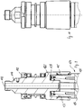
- Fig. 3 the wire feed side or rear end 6 of the arc welding torch device 1 is shown in an exploded view and situation, as it also occurs when the wire core 8a is changed.
- the inlet body 25 is screwed into the end cap 14 during operation of the arc welding torch device 1.
- all seals are inserted in their grooves and remain there even when the wire core is changed.
- the jacket tube 2 is not shown, which is connected unchanged to the end cap 14 by its common screw connection and remains connected even during the change of the wire core 8a.
- the arc welding torch is first dismantled at the process-side end 5 so that the wire core 8a and the guide element 32 can be pulled out of the process-side end 5 together.
- a current arc welding torch from the applicant, in which the invention described here is to be integrated in the future, for example the gas nozzle, a current contact nozzle and possibly a nozzle assembly can be detached from the arc welding torch and removed from the welding wire.
- the wire core 8a can then be pulled out of the arc welding torch from the process-side end 5.
- the guide body 32 seated on the wire core 8a and connected to the latter by a press fit, together with the wire core is pulled out of the arc welding torch device 1.
- the guide element seated in the recess of the end cap and the recess of the inlet body in this exemplary embodiment largely without connection to the two components can thus be pulled out of the two components as well as from the arc welding torch 1 together with the wire core 8a without additional effort, in particular without great effort .
- all that has to be overcome is a comparatively low holding force acting on the outer surface of the guide element through an O-ring seal.
- a new wire core 8a can then be arranged with one of its two ends on the welding wire 7 and inserted into the guide body 32 and arranged.
- the guide body 32 together with the wire core 8a can move into the welding torch and thus also into the arc welding torch device 1 together and in a single operation on the welding wire 7 be inserted.
- This insertion movement in the direction of the end cap 14 is continued until the guide body 32 with its end 32a on the end cap and serving as a position indicator is completely guided through the open through recess 16 of the end cap 14 and the end 32a of the guide element 32 outwards out of the end cap 14 protrudes.
- the optically recognizable end of the guide element 32 which is arranged outside of the arc welding torch device 1 with one of its ends 32a and is optically recognizable, provides a means of checking, without additional technical effort, whether the guide body 32 and the wire core 8a are arranged in their predetermined target positions within the arc welding torch device 1 are. Since the guide body 32 is only sealed against leakage of the protective gas flowing in the arc welding torch device in its target positions, the end 32a of the component of the guide body 32 that is visible outside the end cap 14 also represents a check as to whether the newly introduced wire core 8a and 8a the guide bodies 32 of which are arranged in such a way that the arc welding torch 1 is sealed against escape of protective gas from the end 6 of the arc welding torch 1 on the end cap.
- the component of the guide body 32 has the cylindrical end region section 32a facing the wire feed device in its position of use on the arc welding torch 1, which in the exemplary embodiment is elongated and has a constant outer diameter.
- the end region section 32a merges into a section 32b which enlarges conically towards the end 5 on the process side and which in turn is adjoined by a cylindrical section 32c with a larger, preferably constant, outer diameter.
- section 32c has a shoulder to a slightly reduced outer diameter.
- a front outer diameter of the section 32c in the insertion direction corresponds approximately to the inner diameter of the through recess 25a of the inlet body 25, the guide body becomes in its advancing movement guided within the inlet body.
- the end region section 32a is also aligned in the correct position and in this case arranged concentrically around the longitudinal axis 3 and can be inserted into the through recess 16 of the end cap 14. Since the end region portion 32a has a constant outer diameter which is only slightly smaller than the diameter of the through recess 16, the end region portion 32a can be completely inserted into the through recess and part of the end region portion 32a can be led out of the through recess 16 of the end cap.
- position indicator means This part of the end region section, which can be referred to as position indicator means, is thus recognizable from the outside in its end position in the welding torch 1 and is located comparatively close to the point of application of the wire feed device at which the feed movement is applied to the welding wire 7.
- This position display means can be used for the externally visually perceivable signaling of a correctly positioned arrangement of the guide body and the wire core 8a in the interior of the arc welding torch.
- the one-piece component of the guide body 32 is provided with a through recess 34 which, in the area of the end region section 32a, has a preferably constant diameter which is only slightly larger than the diameter of the welding wire used in this case.
- the through recess 34 In the area of the section 32c with the larger outer diameter, the through recess 34 has a larger, but also constant diameter, as a result of which the rear end of the wire core 8a can be arranged in this area of the through bore.
- the inside diameter of the recess 34 in this area corresponds approximately to the outside diameter of the wire core. With its front end, the wire core 8a abuts the shoulder 34a resulting from the change in diameter in the through recess 34.
- the one-piece nature of the guide body 32 results in good guiding properties for the welding wire in the guide body 32, with at most a low risk of the welding wire 7 getting caught during its movement and thereby buckling.
- Such a system can in particular have identical guide bodies in their geometrical outer shape, but which differ in terms of the diameter of the respective through recess 34 and possibly also in terms of the materials used for the guide elements, whereby an adaptation to the respective material of the welding wire can take place in an advantageous manner.
- the section of the component of the guide element with the smaller outer diameter, which is guided through the end cap 14 and protrudes from it, can be referred to as an anti-kink means.
- the invention also has the advantage that, unlike in the past, the end cap 14 neither guides the welding wire 7 nor the wire core 8a touches and thus the end cap 14, which is usually elaborately designed, is no longer a wearing part.
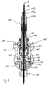
- FIG. 4 and 5 another preferred embodiment of the invention is shown. This is largely identical to the preferred embodiment from FIG Figs. 1 to 3 which is why only the differences are discussed below to avoid repetition. The above description of the Figs. 1 to 3 is therefore also for the embodiment of Fig. 4 and 5 incorporated by reference.
- the main difference to the embodiment of an arc welding torch device according to the Fig. 1-3 consists in the fact that the guide element 32 has (only) a section 32c with a larger diameter, which has a constant diameter throughout, after its conical section 32b, viewed in the direction of the process-side end of the burner.
- the guide element 32 has (only) a section 32c with a larger diameter, which has a constant diameter throughout, after its conical section 32b, viewed in the direction of the process-side end of the burner.
- there is no increase in diameter on the outer surface of the guide element following the conical section - and viewed in the direction of the process-side end - which could be used for a form-fitting and / or force-fitting holding of the guide element.
- there is no sealing element such as the sealing element 33 from the other embodiment of FIG Fig. 2 and 3 , on the outer periphery of the constant diameter portion 32c.
- FIG. 6-13 shows, inter alia, an articulated arm robot 101, as it is already used in many ways.
- the articulated arm robot 101 is designed as a so-called hollow shaft robot, which is particularly suitable in connection with the invention.
- suitable robots can be, for example, the robots of the AR or MA series, which are offered by the company Yaskawa Europe GmbH, 65760 Eschborn.
- the robot has a frame part 102 and an arm 103 which is arranged thereon and which is provided with a plurality of joints 104.
- the free end 105 of the arm of the articulated arm robot 101 is thereby able to follow any three-dimensional movement paths.
- connection flange 106 of a connection device which is used to hold a welding torch 107 ( Fig. 6 ) the arc welding torch device is provided.
- the connecting flange 106 can execute a motor-driven rotational movement about an axis of rotation 108 and relative to the last link of the arm 103.
- a spacer block is drawn in front of the burner, which serves as an extension of the connection flange 106 of the robot and can be provided as an option and not necessarily.
- the arc welding torch 107 shown in more detail has a fastening device 109 and a receiving device 110 ( Fig. 7 ).
- the fastening device 109 is provided to connect the welding torch 107 to the connecting flange 106 of the robot arm 103 in a detachable, but non-rotatable manner.
- the receiving device 110 serves to receive a welding torch neck 111 of the welding torch 107 and to transfer the welding current to the welding torch neck 111, which will be explained in more detail below executing connecting flange 106 of the robot can be connected is, the receiving device 110 and the fastening device 109 are also referred to collectively as part of a rotor which can execute such rotational movements by means of driven movements of the connecting flange about the axis of rotation 108.
- the rotor is non-rotatably connected to the connecting flange, in particular detachably connected.
- the rotor In relation to the last link of the robot arm 103 to which the connecting flange 106 is attached, the rotor can be rotated about the axis 108.
- the robot shown in the figures has a total of six driven axes, this number being only an example of the possible uses of the arc welding torch. In connection with the arc welding torch according to the invention, articulated arm robots with a different number of driven movement axes can also be used.
- a stationary stator located on the inside opposite the rotor and the last link of the robot arm 103 has a tubular passage 114 which is arranged centrally in the welding torch device and has a cylindrical recess 115.
- a longitudinal axis 116 of the recess 115 is aligned with the axis of rotation 108 of the connecting flange 106.
- the bushing 114 extends approximately over the entire length of the fastening device and the receiving device.
- the upper end of the bushing 114 on the robot side is provided with an external thread 117 serving as an electrical connection to which a coaxial cable 118 ( Fig. 6 and Fig. 7 ) can be detachably fastened by screwing on.
- a cone 119 ( Fig. 8 ) can be provided as a conductive contact between a welding current cable 118a of the coaxial cable 118 and the bushing 114.
- the welding current cable 118a which is provided with external insulation 118b, is arranged coaxially around a central channel 118c.
- the central channel 118c can serve to feed the welding wire 7 to the welding torch by means of a feed movement and to allow a protective gas to flow to the front end of the welding torch 107.
- the bushing 114 is surrounded by a bell-shaped section 123 with a circular cross-section ( Fig. 8 and Fig. 9 ) of the stator, which is connected to the bushing in an electrically conductive manner.
- the bell-shaped section 123 and the passage 114 are connected in one piece.
- a contact device 124 which has a slip ring 125 arranged in the bell-shaped section, is arranged essentially inside the bell-shaped section 123 on the leadthrough 114.
- the contact device 124 has a grinding surface 126 formed on the end face on the slip ring 125.
- the grinding surface 126 is force-loaded by a compression spring 127 acting parallel to the longitudinal axis 116 of the feedthrough 114.
- the compression spring 127 is supported on the inside on the bell-shaped section 123 of the stator and presses the grinding surface 126 against a likewise essentially annular surface of a connecting bell 135.
- Both the annular surface of the connecting bell 135 and the grinding surface 126 are part of a contact device 124 and are each concentric arranged around the longitudinal axes 108, 116 and penetrated by a continuation of the recess 115.
- the contact lamellas 145 Between the slip ring 125 and an inside of the bell-shaped section 123 there are contact lamellas 145, which establish the electrical contact between the slip ring 125 and the bell-shaped section 123.
- the spring action of the contact lamellas 145 has the effect that electrical contact is established between the slip ring 125 and an inner surface 133 of the bell-shaped section 123.
- the material of the slip ring 125 is a good electrical conductor, for example copper or a copper alloy.
- the contact lamellas 145 can preferably be silver-plated accordingly in order to ensure a particularly good electrical current transfer.
- the side of the slip ring 125 facing away from the compression spring 127 with its slip surface 126 ( Fig. 9 ) is designed as a stationary component and as part of the stator and acts as an electrical transition to the rotor which is rotatable about the longitudinal axis 108 and to which the connecting bell 135 belongs.
- the connecting bell 135 connects to the slip ring 125 in the direction of the longitudinal axis 116 of the feedthrough 114 and in the direction of the end on the welding torch side ( Fig. 8 ), which is also electrically conductive due to a preferably silver-plated surface.
- the feedthrough 114, the slip ring 125 and the connecting bell 135 have aligned central bores, which overall are part of a central recess 115 running along the longitudinal axis 108.
- the compression spring 127 thus presses on the slip ring 125, which in turn presses on the connecting bell 135 via its grinding surface 126, and the latter is therefore constantly in contact with the grinding surface 126, in particular in electrically conductive contact.
- the connection bell 135 is additionally secured with respect to its axial position on the bushing by means of a ring 148. Furthermore, the connecting bell 135 is paired with the conical outer surface of the “brass flange with socket” 149 via a conical, silver-plated inner surface and is axially centered.
- a seal 136 is located between the bell-shaped element 123 of the stator and the slip ring 125 in a groove 150 of the slip ring 125, with which it can be ensured that the bell-shaped element 123 sits gas-tight on the slip ring 125 as part of the stator.
- a "brass flange with socket" 149 which is paired with the preferably silver-plated connecting bell 135 via a cone, is screwed via a plastic insulating sleeve 151 to a fastening element 152, which is part of the fastening device and serves as a counterpart for the welding torch connection.
- the housing 141, an end cover 142 adjoining one end of the housing 141 and a cover 154 adjoining the other end of the housing 141 in the direction of the welding torch neck 111 are designed as plastic components in the exemplary embodiment.
- the housing 141 also contains the fastening device 109 for fastening to the connecting flange 106 on a hollow-shaft robot and, together with the cover 154 and the end cover 142, encloses and insulates the internal structure electric.
- the receiving device 110 of the welding torch is made of metallic, electrically conductive material, but it is also separated from current-carrying components via the plastic sleeve 151 with a flange as an insulator. The receiving device 110 for the welding torch is accordingly passed through the plastic housing 141 and the cover 154.
- the fastening device 109 embodied as part of the plastic housing 141 is non-rotatably but detachably connected to the connection flange of the robot 106.
- the receiving device 110 for the welding torch, to the fastening element 152 of which a welding torch is releasably connected in a rotationally fixed manner, is also connected non-rotatably to the plastic housing 141.
- the housing 141 which is on the outside of the welding torch, is a component of the rotor of the arc welding torch.
- This rotor is arranged concentrically to the internal stator of the arc welding torch and with respect to the axis of rotation 108 and can rotate about the latter due to motor-driven rotational movements of the connecting flange 106 of the robot relative to the internal stator.
- the stator on the other hand, is stationary when the rotor moves together with the robot-side connecting flange 106 and does not rotate with it.
- this fixed arrangement with respect to the connecting flange 106, the fastening device 109 and the rotor can be achieved overall, for example, in that the welding cable is fastened to the thread 117 of the bushing 114 and is fixed in its rotative position due to the torsional rigidity of the welding cable.
- an additional anti-rotation device for the stator on the robot can also be provided.
- the stator has at least the components, the feedthrough 114 and the slip ring 125 together with the compression spring 127.
- the rotor is mounted on the stator by means of bearings 143, here in the exemplary embodiment ball bearings.
- the plastic housing 141 is closed with the cover 154, which covers the fastening ring 153, towards the welding torch.
- the housing 141 is covered by the cover 142 towards the welding torch cable. If it appears necessary, the stator can also be fixed to a rotationally fixed component of the robot, for example via the cover 142.
- the electrical current required to carry out a welding process flows, beginning with the welding current cable 118a, which is connected to the stator bushing 114 via the screw connection on the external thread 117, and continues in the stator to the bell-shaped section 123. There are the contact lamellas 145 over which the Current is transmitted to the slip ring 125, which also belongs to the stator. The current is transmitted to the silver-plated connecting bell 135 via the sliding contact between the sliding surface 126 and the connecting bell 135.
- the connecting bell 135 is part of the rotor and rotates with a driven rotational movement of the connecting flange 106 together with the housing 141 about the axis of rotation 108 Socket is paired and thus has a tightly pressed fit and thus has good power transmission properties.
- the brass bushing 149 there is another electrically conductive contact lamella 155 X6, with which the welding current is transmitted to the welding torch via an inserted inner tube.
- the burner is fastened via the fastening element 152, which is insulated from the inner tube.
- the protective gas can flow via the coaxial cable 118 through the recess 115 of the feedthrough 114 to the welding torch neck 111.
- the welding wire 7 can also be fed to the welding torch neck 111 in the same way and pushed in each time. If necessary, a data cable (not shown) can be integrated into the coaxial cable 118.
Landscapes
- Engineering & Computer Science (AREA)
- Physics & Mathematics (AREA)
- Plasma & Fusion (AREA)
- Mechanical Engineering (AREA)
- Arc Welding In General (AREA)
Priority Applications (5)
| Application Number | Priority Date | Filing Date | Title |
|---|---|---|---|
| EP19000447.3A EP3799995A1 (fr) | 2019-10-03 | 2019-10-03 | Chalumeau de soudage à l'arc |
| US17/766,229 US20240051054A1 (en) | 2019-10-03 | 2020-12-02 | Arc welding torch |
| CN202080083317.XA CN115038543A (zh) | 2019-10-03 | 2020-12-02 | 电弧焊炬 |
| PCT/IB2020/001071 WO2021064470A2 (fr) | 2019-10-03 | 2020-12-02 | Chalumeau de soudage à l'arc |
| MX2022003898A MX2022003898A (es) | 2019-10-03 | 2020-12-02 | Soplete de soldadura por arco. |
Applications Claiming Priority (1)
| Application Number | Priority Date | Filing Date | Title |
|---|---|---|---|
| EP19000447.3A EP3799995A1 (fr) | 2019-10-03 | 2019-10-03 | Chalumeau de soudage à l'arc |
Publications (1)
| Publication Number | Publication Date |
|---|---|
| EP3799995A1 true EP3799995A1 (fr) | 2021-04-07 |
Family
ID=68158851
Family Applications (1)
| Application Number | Title | Priority Date | Filing Date |
|---|---|---|---|
| EP19000447.3A Pending EP3799995A1 (fr) | 2019-10-03 | 2019-10-03 | Chalumeau de soudage à l'arc |
Country Status (5)
| Country | Link |
|---|---|
| US (1) | US20240051054A1 (fr) |
| EP (1) | EP3799995A1 (fr) |
| CN (1) | CN115038543A (fr) |
| MX (1) | MX2022003898A (fr) |
| WO (1) | WO2021064470A2 (fr) |
Families Citing this family (1)
| Publication number | Priority date | Publication date | Assignee | Title |
|---|---|---|---|---|
| CN116441839B (zh) * | 2023-06-14 | 2023-08-22 | 艾瑞(成都)排放控制技术有限公司 | 端锥焊接夹具 |
Citations (5)
| Publication number | Priority date | Publication date | Assignee | Title |
|---|---|---|---|---|
| DE1540862B1 (de) * | 1963-03-12 | 1971-12-16 | Kjellberg Esab Gmbh | Schweissgeraet fuer das schutzgas lichtbogenschweissen mit abschmelzender elektrode |
| WO2005049259A1 (fr) | 2003-11-21 | 2005-06-02 | Sks Welding Systems Gmbh | Systeme de chalumeau a souder a raccorder a un robot a souder |
| EP1658155A1 (fr) | 2003-08-29 | 2006-05-24 | Tregaskiss Ltd. | Gaine de chargement frontal a plusieurs pieces |
| US20140110386A1 (en) * | 2012-10-23 | 2014-04-24 | Robert J. Centner | Compressible end-fitting for welding gun liner |
| US20170165780A1 (en) * | 2015-12-11 | 2017-06-15 | Illinois Tool Works Inc. | Contact tip and liner assembly for welding torch |
Family Cites Families (8)
| Publication number | Priority date | Publication date | Assignee | Title |
|---|---|---|---|---|
| CN2097709U (zh) * | 1990-08-26 | 1992-03-04 | 罗竞明 | 边槽压条式焊嘴 |
| US6365867B1 (en) * | 2000-11-01 | 2002-04-02 | Sandia Corporation | Plasma arc torch with coaxial wire feed |
| AT413661B (de) * | 2003-05-28 | 2006-04-15 | Fronius Int Gmbh | Puffervorrichtung für einen schweissdraht sowie schweissanlage |
| AT509589B1 (de) * | 2010-06-11 | 2011-10-15 | Fronius Int Gmbh | System zur befestigung einer drahtseele in einer kupplung und drahteinlaufdüse für ein solches befestigungssystem |
| CA2855816A1 (fr) * | 2011-11-13 | 2013-05-16 | Victor Equipment Company | Diffuseur de gaz pour machine mig ou gmaw de soudage a l'arc manuel/robotique, et procede associe au diffuseur de gaz |
| CN104853514A (zh) * | 2015-05-12 | 2015-08-19 | 四川大学 | 层流等离子体发生器 |
| US10675699B2 (en) * | 2015-12-10 | 2020-06-09 | Illinois Tool Works Inc. | Systems, methods, and apparatus to preheat welding wire |
| DE102017006919A1 (de) * | 2017-07-24 | 2019-01-24 | Sks Welding Systems Gmbh | Lichtbogen-Schweißbrenner und dessen Verschleißteile |
-
2019
- 2019-10-03 EP EP19000447.3A patent/EP3799995A1/fr active Pending
-
2020
- 2020-12-02 MX MX2022003898A patent/MX2022003898A/es unknown
- 2020-12-02 CN CN202080083317.XA patent/CN115038543A/zh active Pending
- 2020-12-02 US US17/766,229 patent/US20240051054A1/en active Pending
- 2020-12-02 WO PCT/IB2020/001071 patent/WO2021064470A2/fr active Application Filing
Patent Citations (6)
| Publication number | Priority date | Publication date | Assignee | Title |
|---|---|---|---|---|
| DE1540862B1 (de) * | 1963-03-12 | 1971-12-16 | Kjellberg Esab Gmbh | Schweissgeraet fuer das schutzgas lichtbogenschweissen mit abschmelzender elektrode |
| EP1658155A1 (fr) | 2003-08-29 | 2006-05-24 | Tregaskiss Ltd. | Gaine de chargement frontal a plusieurs pieces |
| WO2005049259A1 (fr) | 2003-11-21 | 2005-06-02 | Sks Welding Systems Gmbh | Systeme de chalumeau a souder a raccorder a un robot a souder |
| EP1689550A1 (fr) | 2003-11-21 | 2006-08-16 | SKS Welding Systems GmbH | Systeme de chalumeau a souder a raccorder a un robot a souder |
| US20140110386A1 (en) * | 2012-10-23 | 2014-04-24 | Robert J. Centner | Compressible end-fitting for welding gun liner |
| US20170165780A1 (en) * | 2015-12-11 | 2017-06-15 | Illinois Tool Works Inc. | Contact tip and liner assembly for welding torch |
Also Published As
| Publication number | Publication date |
|---|---|
| US20240051054A1 (en) | 2024-02-15 |
| WO2021064470A2 (fr) | 2021-04-08 |
| MX2022003898A (es) | 2022-09-29 |
| WO2021064470A3 (fr) | 2021-06-17 |
| CN115038543A (zh) | 2022-09-09 |
Similar Documents
| Publication | Publication Date | Title |
|---|---|---|
| AT508695B1 (de) | Kontaktschale zur kontaktierung eines schweissdrahtes in einem schweissbrenner | |
| EP2800648B1 (fr) | Partie mâle et partie femelle aux fins de l'assemblage amovible d'un coude de tube d'un chalumeau de soudage refroidi par eau ainsi que dispositif d'assemblage | |
| EP2291259B1 (fr) | Tube de contact pour un chalumeau soudeur | |
| AT502844B1 (de) | Schweissbrenner und endstück sowie kontaktrohr für einen schweissbrenner | |
| EP2603345B1 (fr) | Corps de chalumeau muni d'un système de fixation et chalumeau de soudage tig muni d'un tel corps de chalumeau | |
| DE202013102979U1 (de) | Schweißbrenner für das Lichtbogen-Schutzgasschweißen und Kontaktrohr für einen solchen Schweißbrenner | |
| EP1689550B1 (fr) | Systeme de chalumeau a souder a raccorder a un robot a souder | |
| AT508285B1 (de) | Anschlusssystem mit einer kupplungsvorrichtung und einem steckelement für einen schweissbrenner | |
| EP2819803B1 (fr) | Raccords mâle et femelle servant à raccorder de manière démontable un coude d'un chalumeau de soudage refroidi par gaz à un faisceau de flexibles, et système de raccordement équipé de tels raccords mâle et femelle | |
| EP3658325B1 (fr) | Pièce d'usure échangeable pour un chalumeau de soudure à l'arc, support pour pièce d'usure échangeable, et chalumeau de soudure à l'arc avec une telle pièce d'usure correspondante et support | |
| EP3799995A1 (fr) | Chalumeau de soudage à l'arc | |
| EP3799993B1 (fr) | Chalumeau de soudage à l'arc | |
| EP3799994A1 (fr) | Chalumeau de soudage à l'arc | |
| DE102009004307A1 (de) | Handschweißextruder | |
| AT512822B1 (de) | Steckelement für einen Schweißbrenner | |
| AT512825B1 (de) | Stromkupplung für einen Schweißbrenner | |
| AT512824B1 (de) | Kupplung für ein Schlauchpaket eines Schweißbrenners | |
| AT507623B1 (de) | Vorrichtung und verfahren zur kontaktierung eines schweissdrahtes und kontaktschale | |
| AT7856U1 (de) | Abschaltbox für eine roboteranlage und roboteranlage mit einer abschaltbox | |
| DE202004018684U1 (de) | Abschaltbox für eine Roboteranlage und Roboteranlage mit einer Abschaltbox |
Legal Events
| Date | Code | Title | Description |
|---|---|---|---|
| PUAI | Public reference made under article 153(3) epc to a published international application that has entered the european phase |
Free format text: ORIGINAL CODE: 0009012 |
|
| STAA | Information on the status of an ep patent application or granted ep patent |
Free format text: STATUS: THE APPLICATION HAS BEEN PUBLISHED |
|
| AK | Designated contracting states |
Kind code of ref document: A1 Designated state(s): AL AT BE BG CH CY CZ DE DK EE ES FI FR GB GR HR HU IE IS IT LI LT LU LV MC MK MT NL NO PL PT RO RS SE SI SK SM TR |
|
| AX | Request for extension of the european patent |
Extension state: BA ME |
|
| STAA | Information on the status of an ep patent application or granted ep patent |
Free format text: STATUS: REQUEST FOR EXAMINATION WAS MADE |
|
| 17P | Request for examination filed |
Effective date: 20211007 |
|
| STAA | Information on the status of an ep patent application or granted ep patent |
Free format text: STATUS: EXAMINATION IS IN PROGRESS |
|
| 17Q | First examination report despatched |
Effective date: 20231027 |