EP3799971A1 - Vacuum arc remelting (var) processing - Google Patents
Vacuum arc remelting (var) processing Download PDFInfo
- Publication number
- EP3799971A1 EP3799971A1 EP20199897.8A EP20199897A EP3799971A1 EP 3799971 A1 EP3799971 A1 EP 3799971A1 EP 20199897 A EP20199897 A EP 20199897A EP 3799971 A1 EP3799971 A1 EP 3799971A1
- Authority
- EP
- European Patent Office
- Prior art keywords
- crown
- shelf
- vacuum arc
- vibration source
- crucible
- Prior art date
- Legal status (The legal status is an assumption and is not a legal conclusion. Google has not performed a legal analysis and makes no representation as to the accuracy of the status listed.)
- Pending
Links
Images


Classifications
-
- C—CHEMISTRY; METALLURGY
- C22—METALLURGY; FERROUS OR NON-FERROUS ALLOYS; TREATMENT OF ALLOYS OR NON-FERROUS METALS
- C22B—PRODUCTION AND REFINING OF METALS; PRETREATMENT OF RAW MATERIALS
- C22B9/00—General processes of refining or remelting of metals; Apparatus for electroslag or arc remelting of metals
- C22B9/16—Remelting metals
- C22B9/20—Arc remelting
-
- B—PERFORMING OPERATIONS; TRANSPORTING
- B22—CASTING; POWDER METALLURGY
- B22D—CASTING OF METALS; CASTING OF OTHER SUBSTANCES BY THE SAME PROCESSES OR DEVICES
- B22D27/00—Treating the metal in the mould while it is molten or ductile ; Pressure or vacuum casting
-
- B—PERFORMING OPERATIONS; TRANSPORTING
- B22—CASTING; POWDER METALLURGY
- B22D—CASTING OF METALS; CASTING OF OTHER SUBSTANCES BY THE SAME PROCESSES OR DEVICES
- B22D23/00—Casting processes not provided for in groups B22D1/00 - B22D21/00
- B22D23/06—Melting-down metal, e.g. metal particles, in the mould
-
- B—PERFORMING OPERATIONS; TRANSPORTING
- B22—CASTING; POWDER METALLURGY
- B22D—CASTING OF METALS; CASTING OF OTHER SUBSTANCES BY THE SAME PROCESSES OR DEVICES
- B22D7/00—Casting ingots, e.g. from ferrous metals
- B22D7/005—Casting ingots, e.g. from ferrous metals from non-ferrous metals
-
- C—CHEMISTRY; METALLURGY
- C22—METALLURGY; FERROUS OR NON-FERROUS ALLOYS; TREATMENT OF ALLOYS OR NON-FERROUS METALS
- C22B—PRODUCTION AND REFINING OF METALS; PRETREATMENT OF RAW MATERIALS
- C22B9/00—General processes of refining or remelting of metals; Apparatus for electroslag or arc remelting of metals
- C22B9/02—Refining by liquating, filtering, centrifuging, distilling, or supersonic wave action including acoustic waves
- C22B9/026—Refining by liquating, filtering, centrifuging, distilling, or supersonic wave action including acoustic waves by acoustic waves, e.g. supersonic waves
-
- C—CHEMISTRY; METALLURGY
- C22—METALLURGY; FERROUS OR NON-FERROUS ALLOYS; TREATMENT OF ALLOYS OR NON-FERROUS METALS
- C22B—PRODUCTION AND REFINING OF METALS; PRETREATMENT OF RAW MATERIALS
- C22B9/00—General processes of refining or remelting of metals; Apparatus for electroslag or arc remelting of metals
- C22B9/04—Refining by applying a vacuum
-
- F—MECHANICAL ENGINEERING; LIGHTING; HEATING; WEAPONS; BLASTING
- F27—FURNACES; KILNS; OVENS; RETORTS
- F27B—FURNACES, KILNS, OVENS OR RETORTS IN GENERAL; OPEN SINTERING OR LIKE APPARATUS
- F27B3/00—Hearth-type furnaces, e.g. of reverberatory type; Electric arc furnaces ; Tank furnaces
- F27B3/08—Hearth-type furnaces, e.g. of reverberatory type; Electric arc furnaces ; Tank furnaces heated electrically, with or without any other source of heat
- F27B3/085—Arc furnaces
-
- F—MECHANICAL ENGINEERING; LIGHTING; HEATING; WEAPONS; BLASTING
- F27—FURNACES; KILNS; OVENS; RETORTS
- F27D—DETAILS OR ACCESSORIES OF FURNACES, KILNS, OVENS OR RETORTS, IN SO FAR AS THEY ARE OF KINDS OCCURRING IN MORE THAN ONE KIND OF FURNACE
- F27D19/00—Arrangements of controlling devices
-
- F—MECHANICAL ENGINEERING; LIGHTING; HEATING; WEAPONS; BLASTING
- F27—FURNACES; KILNS; OVENS; RETORTS
- F27D—DETAILS OR ACCESSORIES OF FURNACES, KILNS, OVENS OR RETORTS, IN SO FAR AS THEY ARE OF KINDS OCCURRING IN MORE THAN ONE KIND OF FURNACE
- F27D25/00—Devices or methods for removing incrustations, e.g. slag, metal deposits, dust; Devices or methods for preventing the adherence of slag
-
- F—MECHANICAL ENGINEERING; LIGHTING; HEATING; WEAPONS; BLASTING
- F27—FURNACES; KILNS; OVENS; RETORTS
- F27D—DETAILS OR ACCESSORIES OF FURNACES, KILNS, OVENS OR RETORTS, IN SO FAR AS THEY ARE OF KINDS OCCURRING IN MORE THAN ONE KIND OF FURNACE
- F27D7/00—Forming, maintaining or circulating atmospheres in heating chambers
- F27D7/06—Forming or maintaining special atmospheres or vacuum within heating chambers
-
- H—ELECTRICITY
- H05—ELECTRIC TECHNIQUES NOT OTHERWISE PROVIDED FOR
- H05B—ELECTRIC HEATING; ELECTRIC LIGHT SOURCES NOT OTHERWISE PROVIDED FOR; CIRCUIT ARRANGEMENTS FOR ELECTRIC LIGHT SOURCES, IN GENERAL
- H05B7/00—Heating by electric discharge
- H05B7/02—Details
- H05B7/06—Electrodes
- H05B7/07—Electrodes designed to melt in use
-
- Y—GENERAL TAGGING OF NEW TECHNOLOGICAL DEVELOPMENTS; GENERAL TAGGING OF CROSS-SECTIONAL TECHNOLOGIES SPANNING OVER SEVERAL SECTIONS OF THE IPC; TECHNICAL SUBJECTS COVERED BY FORMER USPC CROSS-REFERENCE ART COLLECTIONS [XRACs] AND DIGESTS
- Y02—TECHNOLOGIES OR APPLICATIONS FOR MITIGATION OR ADAPTATION AGAINST CLIMATE CHANGE
- Y02P—CLIMATE CHANGE MITIGATION TECHNOLOGIES IN THE PRODUCTION OR PROCESSING OF GOODS
- Y02P10/00—Technologies related to metal processing
- Y02P10/20—Recycling
-
- Y—GENERAL TAGGING OF NEW TECHNOLOGICAL DEVELOPMENTS; GENERAL TAGGING OF CROSS-SECTIONAL TECHNOLOGIES SPANNING OVER SEVERAL SECTIONS OF THE IPC; TECHNICAL SUBJECTS COVERED BY FORMER USPC CROSS-REFERENCE ART COLLECTIONS [XRACs] AND DIGESTS
- Y02—TECHNOLOGIES OR APPLICATIONS FOR MITIGATION OR ADAPTATION AGAINST CLIMATE CHANGE
- Y02P—CLIMATE CHANGE MITIGATION TECHNOLOGIES IN THE PRODUCTION OR PROCESSING OF GOODS
- Y02P10/00—Technologies related to metal processing
- Y02P10/25—Process efficiency
Definitions
- the present disclosure is directed to the improved vacuum arc remelting processing, and more particularly use of ultrasonic vibration for reduction and/or elimination of dirty white spot defects.
- Inconel 718 (IN718), a nickel-based superalloy, is commonly used for the production of parts exposed to harsh service conditions such as high temperatures.
- IN718 is used for disks, blades, seals, and combustors.
- IN718 is used for high speed parts such as wheels, buckets, and spacers.
- IN718 is also used in the land based gas turbine industry.
- Wrought IN718 parts are produced through forging billet mults using either a triple-melt procedure comprising vacuum induction melting (VIM), electro-slag remelting (ESR), and vacuum arc remelting (VAR), or a double melt procedure (VIM+VAR or VIM+ESR), followed by further thermomechanical processing and forming steps.
- VIP vacuum induction melting
- ESR electro-slag remelting
- VAR vacuum arc remelting
- VIM+VAR or VIM+ESR double melt procedure
- DWSs dirty white spots
- FAA has recommended triple melt for all engine concept designs. While triple melt has been proven to reduce the frequency of DWSs, there are recent examples of these dangerous defects existing in forged parts. As a result, engine original equipment manufacturers (“OEMs”) assume worst-case low cycle fatigue when designing IN718 parts which, in turn, causes parts to be overdesigned leading to even greater energy consumption, longer lead time, and higher cost.
- OEMs engine original equipment manufacturers
- an alloy that will undergo VAR is formed into a cylinder typically by vacuum induction melting (VIM) or ladle refining (airmelt).
- VIM vacuum induction melting
- airmelt airmelt
- This cylinder, referred to as an electrode is then put into a large cylindrical enclosed crucible and brought to a metallurgical vacuum (0.001-0.1 mmHg or 0.1-13.3 Pa).
- a metallurgical vacuum 0.001-0.1 mmHg or 0.1-13.3 Pa.
- the top electrode is brought close to prior to starting the melt.
- Several kiloamperes of DC current are used to start an arc between the two pieces, and from there, a continuous melt is derived.
- the crucible (typically made of copper) is surrounded by a water jacket used to cool the melt and control the solidification rate.
- the diameter of the crucible is larger than that of the electrode.
- the electrode must be lowered as the melt consumes it. Control of the current, cooling water, and electrode gap is required for the effective control of the process, and production of defect free material.
- DWSs form during the VAR process due to the crown and shelf denoted in FIG. 2 , breaking off and falling into the melt pool. These oxide-containing fall-in particles partially remelt before settling in the mushy zone where they are engulfed by the solidification front. DWSs have a different microstructure and contain stringers of oxide particles which contribute to the substantial fatigue life reduction.
- a vacuum arc remelt apparatus comprising a crucible having a wall, the wall having an interior and an exterior opposite the interior; an electrode within the crucible proximate the interior; an ingot within the crucible and below the electrode, wherein the ingot includes a crown and a shelf; and a vibration source at the exterior of the crucible proximate the crown and shelf.
- the vibration source comprises at least one of an ultrasonic transducer and a vibrator.
- the vibrator comprises a mechanical vibrator.
- the ultrasonic transducer is configured to break up the materials of the crown and the shelf during the operation of the vacuum arc remelt apparatus responsive to a predetermined size of the crown and the shelf.
- the apparatus further comprises a microscale model coupled to the vibration source.
- the vibration source controls nucleation and growth mechanics of formation of the crown and the shelf.
- a vacuum arc remelt apparatus comprising a crucible having a side wall, the side wall having an interior and an exterior opposite the interior, a bottom plate coupled to the side wall; an electrode coupled to a stinger, the stinger coupled to a ram configured to translate the electrode within the crucible; an ingot between the electrode and the bottom plate between the side wall proximate the interior, wherein the ingot forms a melt pool and a crown and a shelf responsive to an electrical arc with the electrode; and a vibration source coupled to the exterior and configured to control the nucleation and growth mechanics of formation of the crown and the shelf.
- the vibration source comprises an ultrasonic transducer.
- the ultrasonic transducer is configured to excite portions of the melt pool and lead to the reduction of grain sizes in the ingot.
- the ultrasonic transducer is focused to ultrasonically load the crown and the shelf.
- the vibration source comprises multiple vibration sources configured along the crucible to control the crown and the shelf formation.
- the vibration source comprises a vibrator.
- a process for vacuum arc remelting comprising inserting an ingot between an electrode and a bottom of a crucible of the vacuum arc remelt apparatus, the crucible comprising a wall having an interior and an exterior, the wall being adjacent the bottom; melting the electrode with an arc between the electrode and the ingot; forming a melt pool on top of the ingot proximate the electrode; and vibrating a crown and a shelf proximate the melt pool with a vibration source coupled to the crucible proximate the exterior.
- the vibration source comprises at least one of an ultrasonic transducer and a vibrator.
- the process further comprises exciting portions of the melt pool with the vibration source to reduce grain sizes in the ingot.
- the process further comprises breaking up the materials of the crown and the shelf during the operation of the vacuum arc remelt apparatus with the vibration source.
- the process further comprises focusing the vibration source to ultrasonically load the crown and the shelf.
- the process further comprises employing a microscale model; and determining an ultrasonic frequencies for solidification of the melt pool in the absence of dirty white spots.
- the exemplary vacuum arc remelt process employs ultrasonic waves to break up the crown and the shelf during the VAR process to ensure complete remelt of the particles falling into the melt pool.
- FIG. 3 a schematic diagram of an exemplary vacuum arc remelt apparatus with enhancement is shown.
- the lower portion of the vacuum arc remelt apparatus 10 is shown in FIG. 3 .
- a copper crucible 12 is utilized.
- the copper crucible 12 is water cooled.
- the electrode 14 is shown within the crucible 12 being lowered toward the ingot 16.
- the electrode 14 includes a shrinkage cavity 18.
- the ingot 16 is located opposite the electrode 14 in the crucible 12.
- Vapor deposits 20 are shown along the interior 22 of the wall 24 of the crucible 12. Splatter beads 26 can deposit on the interior 22 of the wall 24.
- the ingot 16 includes a crown 30 and a shelf 36 formed proximate the wall 24 and near the melt pool 28 top surface 32.
- the crown 30 and shelf 36 can be formed by the accumulation of the splatter beads 26, vapor deposits 20 and elevated cooling rate near the interior of the crucible wall 22.
- the crown 30 and shelf 36 include particles containing oxides/nitrides 34 formed from the process.
- the crown 30 and shelf 36 can spawn a potential discrete particle 38 capable of forming a dirty white spot 44. In certain conditions portions 37 of the electrode 14 can break away and fall into the melt pool 28 as well, potentially forming dendritic white spots.
- the fall-in particle 38 that falls into the melt pool 28 and does not completely remelt has the potential to create the dirty white spot 44. If the crown 30 and/or shelf 36 grows to a predetermined size, it may not be capable of remelting. Fall-in particles 38 that break away from the crown 30 and/or shelf 36 can fall into the melt pool 28 and do not completely remelt and fall down and settle into a mushy zone 40. The particles 38 can become engulfed into a solidification front 42. These particles 38 can form the dirty white spots 44.
- a vibration source 46 can be coupled to the apparatus 10 and configured to break up the materials of the crown 30 and shelf 36 during the operation of the vacuum arc remelt process.
- the vibration source 46 can be coupled proximate the exterior 25 of the wall 24.
- the vibration source 46 controls the nucleation and growth mechanics of formation of the crown 30 and shelf 36.
- the vibration source 46 can decrease grain size, alter solidification rate, and significantly affect crystal structure and nucleation and growth behavior.
- the vibration source 46 can be configured to drive down the size of the crown 30 and shelf 36 to a minimal size. Thus, reducing the chance of fall-in particles 38 reaching the mushy zone 40 prior to remelting.
- the vibration source 46 can excite the resonance to promote rapid fatigue, fracture, and subsequent fall-in of the particle 38 before the particle 38 can reach a critical size that can precipitate the dirty white spot 44.
- the vibration source 46 can be mobile and move along the crucible 12 to optimize the influence on the crown 30 and shelf 36. Multiple vibration sources 46 are also contemplated and can be configured along the crucible 12 to control the crown 30 and shelf 36 formation.
- the vibration source 46 can be an ultrasonic transducer 48.
- the ultrasonic transducer 48 can be configured to emit ultrasonic waves 50.
- the ultrasonic transducer 48 can be focused to ultrasonically load the crown 30 and shelf 36.
- the oxide particles 34 can become brittle within the crown 30 and shelf 36 and serve as initiation points for fatigue cracks.
- the ultrasonic transducer 48 can also excite portions of the melt pool 28 and lead to the reduction of grain sizes in the ingot 16 and slow down the solidification process.
- an array of ultrasonic transducers 48 can be employed.
- the transducers 48 can be configured to emit the ultrasonic waves 50 at an optimum location around the crown 30 and shelf 36.
- the vibration source 46 can include a mechanical vibrator 52.
- the vibrator 52 can generate mechanical vibration that transmits to the crown 30 and shelf 36 and breaks the crown 30 and shelf 36 down prior to buildup.
- the mechanical vibrator 52 can be configured to produce mechanical vibration in a range having a frequency of from 50 Hz to 200 Hz; and a force of up to 3500 pounds (15.6 kN) of centrifugal force.
- the applied vibration parameters (amplitude, frequency, location, direction) will be tailored to reduce crown 30 and shelf 36 formation and mitigate fall-in particle 38 frequency.
- Multiple mechanisms contribute to crown 30 and shelf 36 formation including vapor deposits 20 and splatter beads 26 on the inside surface 22 of the crucible wall 24 as well as growth of the crown 30 and shelf 36 above the liquid line due to contact of the liquid 28 with the crucible wall and elevated cooling rate in this location. Exciting a range of frequencies from sonic (20 Hz - 20 kHz) to ultrasonic (>20 kHz) will ensure that each of these mechanisms is addressed with a suitable vibratory signature.
- solidifying material adhering to the crucible wall could be released using sonic energy while the resonance excitation of the small crown 30 would require ultrasonic vibration.
- an ultrasonic frequency range of 50 kHz - 400 kHz would excite the first natural frequency of the crown 30. This will in turn promote rapid fatigue, fracture, and subsequent fall-in of the particle 38 before it reaches a size that will not remelt.
- the vibration source 46 can be utilized to minimize the likelihood of dirty white spot formation due to fall-in particles 38 during the vacuum arc remelt process can be determined employing a microscale model 54.
- microscale model 54 coupled with a VAR model 56, 54 will be used to provide valuable insight into the process, including the critical fall-in particle 38 size for full remelting.
- the microscale model 54 can be configured as a physics-based model capable of resolving the microstructure of the fall-in particles 38 including its grain structure and oxide/nitride stringers (micron scale resolution) and can be employed to inform/tune the VAR process parameters and sonic/ultrasonic method operating conditions (amplitude, frequency).
- the model 54 can be executed prior to running the VAR process in order to optimize the parameters to minimize crown 30 and shelf 36 formation and fall-in particle 38 frequency.
- Models are currently used to aid in choosing VAR process parameters. However, these models lack the resolution to simulate the details associated with the crown 30 and shelf 36 and fall-in particles 38 (microstructural details) that must be considered to optimize the process under conditions of crown 30 and shelf 36 formation, fracture, and creation of fall-in particles 38. These details include the interaction of the fall-in particle 38 with the temperature and velocity field in the melt pool 28 as well as the effect of the sonic/ultrasonic vibration on the solidifying material.
- the ideal ultrasonic frequencies for solidification can also be determined. Key parameters such as ultrasonic wave type, orientation, and frequency can be considered in the model and the output used to inform the VAR process.
- the models can be used to evaluate whether it is possible to fully melt the particle 38 before it reaches the mushy zone 40 and provide guidance to the necessary ultrasonic field intensity to control solidification.
- the ultrasonic transducer can be configured to break up the materials of the crown 30 and shelf 36 during the operation of the vacuum arc remelt apparatus 10 responsive to a predetermined size of the crown 30 and shelf 36.
- the models can be utilized to determine the predetermined size of the crown 30 and shelf 36, depending on the variables related to the VAR and materials being processed.
- An advantage of the vacuum arc remelt process includes greater life and durability of parts due to the elimination of DWSs in the triple melt process, which would lead to an equivalent cost reduction.
Landscapes
- Engineering & Computer Science (AREA)
- Chemical & Material Sciences (AREA)
- Mechanical Engineering (AREA)
- Physics & Mathematics (AREA)
- Manufacturing & Machinery (AREA)
- Materials Engineering (AREA)
- Metallurgy (AREA)
- Organic Chemistry (AREA)
- Acoustics & Sound (AREA)
- General Engineering & Computer Science (AREA)
- Plasma & Fusion (AREA)
- Manufacture And Refinement Of Metals (AREA)
Abstract
Description
- The present disclosure is directed to the improved vacuum arc remelting processing, and more particularly use of ultrasonic vibration for reduction and/or elimination of dirty white spot defects.
- Inconel 718 (IN718), a nickel-based superalloy, is commonly used for the production of parts exposed to harsh service conditions such as high temperatures. For aerospace engines, IN718 is used for disks, blades, seals, and combustors. In the airframe industry, IN718 is used for high speed parts such as wheels, buckets, and spacers. IN718 is also used in the land based gas turbine industry.
- Wrought IN718 parts are produced through forging billet mults using either a triple-melt procedure comprising vacuum induction melting (VIM), electro-slag remelting (ESR), and vacuum arc remelting (VAR), or a double melt procedure (VIM+VAR or VIM+ESR), followed by further thermomechanical processing and forming steps.
- The VAR process, while very energy, time, and cost intensive, has been designed to achieve clean, defect-free material. One defect that has been gaining recent attention is called dirty white spots (DWSs). DWSs are often difficult or even impossible to detect in forged parts processed using VAR. As such, they can lead to devastating (> 30x reduction) effects on fatigue life.
- FAA has recommended triple melt for all engine concept designs. While triple melt has been proven to reduce the frequency of DWSs, there are recent examples of these dangerous defects existing in forged parts. As a result, engine original equipment manufacturers ("OEMs") assume worst-case low cycle fatigue when designing IN718 parts which, in turn, causes parts to be overdesigned leading to even greater energy consumption, longer lead time, and higher cost.
- Referring to
FIG. 1 an alloy that will undergo VAR is formed into a cylinder typically by vacuum induction melting (VIM) or ladle refining (airmelt). This cylinder, referred to as an electrode is then put into a large cylindrical enclosed crucible and brought to a metallurgical vacuum (0.001-0.1 mmHg or 0.1-13.3 Pa). At the bottom of the crucible is a small amount of the alloy to be remelted, which the top electrode is brought close to prior to starting the melt. Several kiloamperes of DC current are used to start an arc between the two pieces, and from there, a continuous melt is derived. The crucible (typically made of copper) is surrounded by a water jacket used to cool the melt and control the solidification rate. To prevent arcing between the electrode and the crucible side walls, the diameter of the crucible is larger than that of the electrode. As a result, the electrode must be lowered as the melt consumes it. Control of the current, cooling water, and electrode gap is required for the effective control of the process, and production of defect free material. - However, as seen in
FIG. 2 , DWSs form during the VAR process due to the crown and shelf denoted inFIG. 2 , breaking off and falling into the melt pool. These oxide-containing fall-in particles partially remelt before settling in the mushy zone where they are engulfed by the solidification front. DWSs have a different microstructure and contain stringers of oxide particles which contribute to the substantial fatigue life reduction. - In accordance with the present invention, there is provided a vacuum arc remelt apparatus comprising a crucible having a wall, the wall having an interior and an exterior opposite the interior; an electrode within the crucible proximate the interior; an ingot within the crucible and below the electrode, wherein the ingot includes a crown and a shelf; and a vibration source at the exterior of the crucible proximate the crown and shelf.
- In an optional embodiment, the vibration source comprises at least one of an ultrasonic transducer and a vibrator.
- In an optional embodiment, the vibrator comprises a mechanical vibrator.
- In an optional embodiment, the ultrasonic transducer is configured to break up the materials of the crown and the shelf during the operation of the vacuum arc remelt apparatus responsive to a predetermined size of the crown and the shelf.
- In an optional embodiment, the apparatus further comprises a microscale model coupled to the vibration source.
- In an optional embodiment, the vibration source controls nucleation and growth mechanics of formation of the crown and the shelf.
- In accordance with the present invention, there is provided a vacuum arc remelt apparatus comprising a crucible having a side wall, the side wall having an interior and an exterior opposite the interior, a bottom plate coupled to the side wall; an electrode coupled to a stinger, the stinger coupled to a ram configured to translate the electrode within the crucible; an ingot between the electrode and the bottom plate between the side wall proximate the interior, wherein the ingot forms a melt pool and a crown and a shelf responsive to an electrical arc with the electrode; and a vibration source coupled to the exterior and configured to control the nucleation and growth mechanics of formation of the crown and the shelf.
- In an optional embodiment, the vibration source comprises an ultrasonic transducer.
- In an optional embodiment, the ultrasonic transducer is configured to excite portions of the melt pool and lead to the reduction of grain sizes in the ingot.
- In an optional embodiment, the ultrasonic transducer is focused to ultrasonically load the crown and the shelf.
- In an optional embodiment, the vibration source comprises multiple vibration sources configured along the crucible to control the crown and the shelf formation.
- In an optional embodiment, the vibration source comprises a vibrator.
- In accordance with the present invention, there is provided a process for vacuum arc remelting comprising inserting an ingot between an electrode and a bottom of a crucible of the vacuum arc remelt apparatus, the crucible comprising a wall having an interior and an exterior, the wall being adjacent the bottom; melting the electrode with an arc between the electrode and the ingot; forming a melt pool on top of the ingot proximate the electrode; and vibrating a crown and a shelf proximate the melt pool with a vibration source coupled to the crucible proximate the exterior.
- In an optional embodiment, the vibration source comprises at least one of an ultrasonic transducer and a vibrator.
- In an optional embodiment, the process further comprises exciting portions of the melt pool with the vibration source to reduce grain sizes in the ingot.
- In an optional embodiment, the process further comprises breaking up the materials of the crown and the shelf during the operation of the vacuum arc remelt apparatus with the vibration source.
- In an optional embodiment, the process further comprises focusing the vibration source to ultrasonically load the crown and the shelf.
- In an optional embodiment, the process further comprises employing a microscale model; and determining an ultrasonic frequencies for solidification of the melt pool in the absence of dirty white spots.
- The exemplary vacuum arc remelt process employs ultrasonic waves to break up the crown and the shelf during the VAR process to ensure complete remelt of the particles falling into the melt pool.
- Other details of the VAR process are set forth in the following detailed description and the accompanying drawings wherein like reference numerals depict like elements. Any of the above described embodiments can be combined to improve the technical effect of the VAR process.
-
-
FIG. 1 is a prior art schematic diagram of an exemplary vacuum arc remelt apparatus. -
FIG. 2 is a prior art schematic diagram of an exemplary vacuum arc remelt process with formation of dirty white spots. -
FIG. 3 is a schematic diagram of an exemplary vacuum arc remelt process with enhancement. -
FIG. 4 is a schematic diagram of exemplary vacuum arc remelt models. - Referring now to
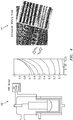
FIG. 3 , a schematic diagram of an exemplary vacuum arc remelt apparatus with enhancement is shown. The lower portion of the vacuumarc remelt apparatus 10 is shown inFIG. 3 . Acopper crucible 12 is utilized. Thecopper crucible 12 is water cooled. Theelectrode 14 is shown within thecrucible 12 being lowered toward theingot 16. Theelectrode 14 includes ashrinkage cavity 18. Theingot 16 is located opposite theelectrode 14 in thecrucible 12.Vapor deposits 20 are shown along theinterior 22 of thewall 24 of thecrucible 12.Splatter beads 26 can deposit on theinterior 22 of thewall 24. - As the
electrode 14 is melted, amelt pool 28, liquid ingot material, is formed between theelectrode 14 and portions of theingot 16 that has solidified. Theingot 16 includes acrown 30 and ashelf 36 formed proximate thewall 24 and near themelt pool 28top surface 32. Thecrown 30 andshelf 36 can be formed by the accumulation of thesplatter beads 26,vapor deposits 20 and elevated cooling rate near the interior of thecrucible wall 22. Thecrown 30 andshelf 36 include particles containing oxides/nitrides 34 formed from the process. Thecrown 30 andshelf 36 can spawn a potentialdiscrete particle 38 capable of forming a dirty white spot 44. In certain conditions portions 37 of theelectrode 14 can break away and fall into themelt pool 28 as well, potentially forming dendritic white spots. The fall-inparticle 38 that falls into themelt pool 28 and does not completely remelt has the potential to create the dirty white spot 44. If thecrown 30 and/orshelf 36 grows to a predetermined size, it may not be capable of remelting. Fall-inparticles 38 that break away from thecrown 30 and/orshelf 36 can fall into themelt pool 28 and do not completely remelt and fall down and settle into amushy zone 40. Theparticles 38 can become engulfed into asolidification front 42. Theseparticles 38 can form the dirty white spots 44. - A
vibration source 46 can be coupled to theapparatus 10 and configured to break up the materials of thecrown 30 andshelf 36 during the operation of the vacuum arc remelt process. Thevibration source 46 can be coupled proximate theexterior 25 of thewall 24. Thevibration source 46 controls the nucleation and growth mechanics of formation of thecrown 30 andshelf 36. Thevibration source 46 can decrease grain size, alter solidification rate, and significantly affect crystal structure and nucleation and growth behavior. Thevibration source 46 can be configured to drive down the size of thecrown 30 andshelf 36 to a minimal size. Thus, reducing the chance of fall-inparticles 38 reaching themushy zone 40 prior to remelting. Thevibration source 46 can excite the resonance to promote rapid fatigue, fracture, and subsequent fall-in of theparticle 38 before theparticle 38 can reach a critical size that can precipitate the dirty white spot 44. Thevibration source 46 can be mobile and move along thecrucible 12 to optimize the influence on thecrown 30 andshelf 36.Multiple vibration sources 46 are also contemplated and can be configured along thecrucible 12 to control thecrown 30 andshelf 36 formation. - In an exemplary embodiment, the
vibration source 46 can be anultrasonic transducer 48. Theultrasonic transducer 48 can be configured to emitultrasonic waves 50. Theultrasonic transducer 48 can be focused to ultrasonically load thecrown 30 andshelf 36. Theoxide particles 34 can become brittle within thecrown 30 andshelf 36 and serve as initiation points for fatigue cracks. Theultrasonic transducer 48 can also excite portions of themelt pool 28 and lead to the reduction of grain sizes in theingot 16 and slow down the solidification process. - In an exemplary embodiment, an array of
ultrasonic transducers 48 can be employed. Thetransducers 48 can be configured to emit theultrasonic waves 50 at an optimum location around thecrown 30 andshelf 36. - In an alternative embodiment, the
vibration source 46 can include amechanical vibrator 52. Thevibrator 52 can generate mechanical vibration that transmits to thecrown 30 andshelf 36 and breaks thecrown 30 andshelf 36 down prior to buildup. Themechanical vibrator 52 can be configured to produce mechanical vibration in a range having a frequency of from 50 Hz to 200 Hz; and a force of up to 3500 pounds (15.6 kN) of centrifugal force. - The applied vibration parameters (amplitude, frequency, location, direction) will be tailored to reduce
crown 30 andshelf 36 formation and mitigate fall-inparticle 38 frequency. Multiple mechanisms contribute to crown 30 andshelf 36 formation includingvapor deposits 20 andsplatter beads 26 on theinside surface 22 of thecrucible wall 24 as well as growth of thecrown 30 andshelf 36 above the liquid line due to contact of the liquid 28 with the crucible wall and elevated cooling rate in this location. Exciting a range of frequencies from sonic (20 Hz - 20 kHz) to ultrasonic (>20 kHz) will ensure that each of these mechanisms is addressed with a suitable vibratory signature. For example, solidifying material adhering to the crucible wall could be released using sonic energy while the resonance excitation of thesmall crown 30 would require ultrasonic vibration. Specifically, based on the typical size of fall-inparticles 38 originating from thecrown 30 and their mechanical properties, an ultrasonic frequency range of 50 kHz - 400 kHz would excite the first natural frequency of thecrown 30. This will in turn promote rapid fatigue, fracture, and subsequent fall-in of theparticle 38 before it reaches a size that will not remelt. Thevibration source 46 can be utilized to minimize the likelihood of dirty white spot formation due to fall-inparticles 38 during the vacuum arc remelt process can be determined employing amicroscale model 54. - The
microscale model 54 coupled with aVAR model 56, 54) will be used to provide valuable insight into the process, including the critical fall-inparticle 38 size for full remelting. - The
microscale model 54 can be configured as a physics-based model capable of resolving the microstructure of the fall-inparticles 38 including its grain structure and oxide/nitride stringers (micron scale resolution) and can be employed to inform/tune the VAR process parameters and sonic/ultrasonic method operating conditions (amplitude, frequency). Themodel 54 can be executed prior to running the VAR process in order to optimize the parameters to minimizecrown 30 andshelf 36 formation and fall-inparticle 38 frequency. Models are currently used to aid in choosing VAR process parameters. However, these models lack the resolution to simulate the details associated with thecrown 30 andshelf 36 and fall-in particles 38 (microstructural details) that must be considered to optimize the process under conditions ofcrown 30 andshelf 36 formation, fracture, and creation of fall-inparticles 38. These details include the interaction of the fall-inparticle 38 with the temperature and velocity field in themelt pool 28 as well as the effect of the sonic/ultrasonic vibration on the solidifying material. - Using the
microscale model 54, the ideal ultrasonic frequencies for solidification can also be determined. Key parameters such as ultrasonic wave type, orientation, and frequency can be considered in the model and the output used to inform the VAR process. The models can be used to evaluate whether it is possible to fully melt theparticle 38 before it reaches themushy zone 40 and provide guidance to the necessary ultrasonic field intensity to control solidification. The ultrasonic transducer can be configured to break up the materials of thecrown 30 andshelf 36 during the operation of the vacuum arc remeltapparatus 10 responsive to a predetermined size of thecrown 30 andshelf 36. The models can be utilized to determine the predetermined size of thecrown 30 andshelf 36, depending on the variables related to the VAR and materials being processed. - An advantage of the vacuum arc remelt process includes greater life and durability of parts due to the elimination of DWSs in the triple melt process, which would lead to an equivalent cost reduction.
- Another advantage comes with the reduction in DWSs, part designers can prescribe life based on less conservative estimates, making the overall manufacturing process less costly, less time consuming, and less energy intensive. Additionally, significant increase in safety will result.
- There has been provided a vacuum arc remelt process. While the vacuum arc remelt process has been described in the context of specific embodiments thereof, other unforeseen alternatives, modifications, and variations may become apparent to those skilled in the art having read the foregoing description. Accordingly, it is intended to embrace those alternatives, modifications, and variations which fall within the broad scope of the appended claims.
Claims (15)
- A vacuum arc remelt apparatus (10) comprising:a crucible (12) having a wall (24), said wall having an interior (22) and an exterior (25) opposite said interior (22);an electrode (14) within the crucible (12) proximate the interior (22);an ingot (16) within the crucible (12) and below the electrode (14), wherein said ingot (16) includes a crown (30) and a shelf (36); anda vibration source (46) at the exterior (25) of the crucible (12) proximate the crown (30) and shelf (36).
- The vacuum arc remelt apparatus (10) according to claim 1, wherein said vibration source (46) comprises at least one of an ultrasonic transducer (48) and a vibrator (52).
- The vacuum arc remelt apparatus (10) according to claim 2, wherein said vibrator (52) comprises a mechanical vibrator.
- The vacuum arc remelt apparatus (10) according to claim 2 or 3, wherein said ultrasonic transducer (48) is configured to break up the materials of the crown (30) and shelf (36) during the operation of the vacuum arc remelt apparatus (10) responsive to a predetermined size of the crown (30) and shelf (36).
- The vacuum arc remelt apparatus (10) according to any preceding claim, further comprising a microscale model (54) coupled to the vibration source (46).
- The vacuum arc remelt apparatus (10) according to any preceding claim, wherein said vibration source (46) controls nucleation and growth mechanics of formation of the crown (30) and shelf (36).
- A vacuum arc remelt apparatus (10) comprising:a crucible (12) having a side wall (24), said side wall (24) having an interior (22) and an exterior (25) opposite said interior (22), a bottom plate coupled to said side wall (24);an electrode (14) coupled to a stinger, said stinger coupled to a ram configured to translate said electrode (14) within said crucible (12);an ingot (16) between said electrode (14) and said bottom plate between said side wall (24) proximate the interior (22), wherein said electrode (14) forms a melt pool (28) and a crown (30) and a shelf (36) responsive to an electrical arc with said ingot (16); anda vibration source (46) coupled to said exterior (25) and configured to control the nucleation and growth mechanics of formation of the crown (30) and shelf (36).
- The vacuum arc remelt apparatus (10) according to claim 7, wherein said vibration source (46) comprises an ultrasonic transducer (48),
wherein optionally:said ultrasonic transducer (48) is configured to excite portions of the melt pool (28) and lead to the reduction of grain sizes in the ingot (16); and/orsaid ultrasonic transducer (48) is focused to ultrasonically load the crown (30) and shelf (36). - The vacuum arc remelt apparatus (10) according to claim 7 or 8, wherein said vibration source (46) comprises multiple vibration sources configured along the crucible (12) to control the crown (30) and shelf (36) formation.
- The vacuum arc remelt apparatus (10) according to claim 7, 8, or 9, wherein said vibration source (46) comprises a vibrator (52) .
- A process for vacuum arc remelting comprising:inserting an ingot (16) between an electrode (14) and a bottom of a crucible (12) of the vacuum arc remelt apparatus (10), said crucible (12) comprising a wall (24) having an interior (22) and an exterior (25), said wall (24) being adjacent said bottom;melting said electrode (14) with an arc between said electrode (14) and said ingot (16);forming a melt pool (28) on top of said ingot (16) proximate said electrode (14); andvibrating a crown (30) and shelf (36) proximate said melt pool (28) with a vibration source (46) coupled to said crucible (12) proximate said exterior (25),wherein said vibration source (46) optionally comprises at least one of an ultrasonic transducer (48) and a vibrator (52).
- The process of claim 11, further comprising:
exciting portions of the melt pool (28) with said vibration source (46) to reduce grain sizes in the ingot (16). - The process of claim 11 or 12, further comprising:
breaking up the materials of the crown (30) and shelf (36) during the operation of the vacuum arc remelt apparatus (10) with said vibration source (46). - The process of claim 11, 12, or 13 further comprising:
focusing the vibration source (46) to ultrasonically load the crown (30) and shelf (36). - The process of any of claims 11 to 14 further comprising:employing a microscale model (54); anddetermining ultrasonic frequencies for solidification of said melt pool (28) in the absence of dirty white spots (44).
Applications Claiming Priority (1)
| Application Number | Priority Date | Filing Date | Title |
|---|---|---|---|
| US16/590,763 US11512366B2 (en) | 2019-10-02 | 2019-10-02 | Vacuum arc remelting processing |
Publications (1)
| Publication Number | Publication Date |
|---|---|
| EP3799971A1 true EP3799971A1 (en) | 2021-04-07 |
Family
ID=72744678
Family Applications (1)
| Application Number | Title | Priority Date | Filing Date |
|---|---|---|---|
| EP20199897.8A Pending EP3799971A1 (en) | 2019-10-02 | 2020-10-02 | Vacuum arc remelting (var) processing |
Country Status (2)
| Country | Link |
|---|---|
| US (1) | US11512366B2 (en) |
| EP (1) | EP3799971A1 (en) |
Families Citing this family (3)
| Publication number | Priority date | Publication date | Assignee | Title |
|---|---|---|---|---|
| US11512366B2 (en) * | 2019-10-02 | 2022-11-29 | Raytheon Technologies Corporation | Vacuum arc remelting processing |
| CN115029560B (en) * | 2022-06-01 | 2024-02-20 | 哈尔滨工业大学 | A device and method for directly and indirectly coupling ultrasonic treatment of high-temperature melt |
| US20250277286A1 (en) * | 2024-03-01 | 2025-09-04 | Titanium Metals Corporation | Shelf detection and control for vacuum arc remelting |
Citations (4)
| Publication number | Priority date | Publication date | Assignee | Title |
|---|---|---|---|---|
| CA740057A (en) * | 1966-08-02 | H. Lane Donald | Method and apparatus for forming ingots | |
| EP1184470A2 (en) * | 2000-08-31 | 2002-03-06 | General Electric Company | Vacuum arc remelting apparatus and process |
| JP2013066920A (en) * | 2011-09-25 | 2013-04-18 | Nissan Motor Co Ltd | Method for manufacturing aluminum alloy casting material |
| CN106756137B (en) * | 2016-12-02 | 2018-06-29 | 中国航空工业集团公司北京航空材料研究院 | A kind of device and method of titanium alloy vacuum consumable electric arc melting crystal grain thinning |
Family Cites Families (3)
| Publication number | Priority date | Publication date | Assignee | Title |
|---|---|---|---|---|
| US3193889A (en) * | 1961-07-24 | 1965-07-13 | Westinghouse Electric Corp | Method and apparatus for producing uniform grain refinement in metal ingots |
| US20140255620A1 (en) | 2013-03-06 | 2014-09-11 | Rolls-Royce Corporation | Sonic grain refinement of laser deposits |
| US11512366B2 (en) * | 2019-10-02 | 2022-11-29 | Raytheon Technologies Corporation | Vacuum arc remelting processing |
-
2019
- 2019-10-02 US US16/590,763 patent/US11512366B2/en active Active
-
2020
- 2020-10-02 EP EP20199897.8A patent/EP3799971A1/en active Pending
Patent Citations (4)
| Publication number | Priority date | Publication date | Assignee | Title |
|---|---|---|---|---|
| CA740057A (en) * | 1966-08-02 | H. Lane Donald | Method and apparatus for forming ingots | |
| EP1184470A2 (en) * | 2000-08-31 | 2002-03-06 | General Electric Company | Vacuum arc remelting apparatus and process |
| JP2013066920A (en) * | 2011-09-25 | 2013-04-18 | Nissan Motor Co Ltd | Method for manufacturing aluminum alloy casting material |
| CN106756137B (en) * | 2016-12-02 | 2018-06-29 | 中国航空工业集团公司北京航空材料研究院 | A kind of device and method of titanium alloy vacuum consumable electric arc melting crystal grain thinning |
Also Published As
| Publication number | Publication date |
|---|---|
| US20210102272A1 (en) | 2021-04-08 |
| US11512366B2 (en) | 2022-11-29 |
Similar Documents
| Publication | Publication Date | Title |
|---|---|---|
| EP3799971A1 (en) | Vacuum arc remelting (var) processing | |
| RU2716967C2 (en) | Alloy melting and refining method | |
| Campbell | The consolidation of metals: The origin of bifilms | |
| Campbell | Effects of vibration during solidification | |
| US7722330B2 (en) | Rotating apparatus disk | |
| CN107812942A (en) | A kind of double ultrasonic wave added laser gain material manufacture devices and method | |
| CN102310174B (en) | Method and device for improving metal solidification defects and refining solidification textures | |
| Schilke et al. | Alloy 706 metallurgy and turbine wheel application | |
| US7114548B2 (en) | Method and apparatus for treating articles during formation | |
| Ma et al. | Grain refinement effect of a pulsed magnetic field on as-cast superalloy K417 | |
| CN113403491B (en) | Production method of high-temperature alloy | |
| Honnorat | Issues and breakthrough in the manufacture of turboengine titanium parts | |
| Xu et al. | Tree-ring formation during vacuum arc remelting of INCONEL 718: Part I. Experimental investigation | |
| Xie et al. | Effect of process parameters on microstructure and properties of superalloy turbine guide castings by a novel electromagnetic oscillation method | |
| CN115922028A (en) | A Welding Method Using Low Frequency Resonance to Improve the Properties of Cladding Metal | |
| Kennedy et al. | Superalloys made by conventional vacuum melting and a novel spray forming process | |
| CN115558811B (en) | Equipment and method for preparing TiAl semi-solid material by utilizing ultrasonic and electromagnetic field | |
| EP2633926B1 (en) | Ring-shaped clean metal casting mold | |
| Beeley | Application to aerospace | |
| CN115255304B (en) | A continuous casting method for controlling macroscopic inclusions in steel | |
| Mitchell | Recent developments in specialty melting processes | |
| JPH09241767A (en) | Consumable electrode type remelting method for superalloy | |
| Mitchell | Melting processes and solidification in alloys 718-625 | |
| Komarov et al. | Development and application of large-sized sonotrode systems for ultrasonic treatment of molten aluminum alloys | |
| CN202517033U (en) | Device for overcoming metal solidification defect and refining solidification structure |
Legal Events
| Date | Code | Title | Description |
|---|---|---|---|
| PUAI | Public reference made under article 153(3) epc to a published international application that has entered the european phase |
Free format text: ORIGINAL CODE: 0009012 |
|
| STAA | Information on the status of an ep patent application or granted ep patent |
Free format text: STATUS: THE APPLICATION HAS BEEN PUBLISHED |
|
| AK | Designated contracting states |
Kind code of ref document: A1 Designated state(s): AL AT BE BG CH CY CZ DE DK EE ES FI FR GB GR HR HU IE IS IT LI LT LU LV MC MK MT NL NO PL PT RO RS SE SI SK SM TR |
|
| AX | Request for extension of the european patent |
Extension state: BA ME |
|
| STAA | Information on the status of an ep patent application or granted ep patent |
Free format text: STATUS: REQUEST FOR EXAMINATION WAS MADE |
|
| 17P | Request for examination filed |
Effective date: 20211007 |
|
| RBV | Designated contracting states (corrected) |
Designated state(s): AL AT BE BG CH CY CZ DE DK EE ES FI FR GB GR HR HU IE IS IT LI LT LU LV MC MK MT NL NO PL PT RO RS SE SI SK SM TR |
|
| RAP3 | Party data changed (applicant data changed or rights of an application transferred) |
Owner name: RTX CORPORATION |
|
| STAA | Information on the status of an ep patent application or granted ep patent |
Free format text: STATUS: EXAMINATION IS IN PROGRESS |
|
| 17Q | First examination report despatched |
Effective date: 20260126 |