EP3799544B1 - Steuergeräte für haustechnikanlage - Google Patents
Steuergeräte für haustechnikanlage Download PDFInfo
- Publication number
- EP3799544B1 EP3799544B1 EP20197366.6A EP20197366A EP3799544B1 EP 3799544 B1 EP3799544 B1 EP 3799544B1 EP 20197366 A EP20197366 A EP 20197366A EP 3799544 B1 EP3799544 B1 EP 3799544B1
- Authority
- EP
- European Patent Office
- Prior art keywords
- electronic module
- printed circuit
- plate element
- control appliance
- module
- Prior art date
- Legal status (The legal status is an assumption and is not a legal conclusion. Google has not performed a legal analysis and makes no representation as to the accuracy of the status listed.)
- Active
Links
- 238000009434 installation Methods 0.000 title claims description 5
- 239000002184 metal Substances 0.000 claims description 8
- 229910052751 metal Inorganic materials 0.000 claims description 8
- 229910000831 Steel Inorganic materials 0.000 claims 1
- 239000010959 steel Substances 0.000 claims 1
- 230000002787 reinforcement Effects 0.000 description 16
- 230000006870 function Effects 0.000 description 9
- 239000004973 liquid crystal related substance Substances 0.000 description 3
- 238000000034 method Methods 0.000 description 3
- 238000005096 rolling process Methods 0.000 description 3
- RYGMFSIKBFXOCR-UHFFFAOYSA-N Copper Chemical compound [Cu] RYGMFSIKBFXOCR-UHFFFAOYSA-N 0.000 description 2
- 230000021615 conjugation Effects 0.000 description 2
- 229910052802 copper Inorganic materials 0.000 description 2
- 239000010949 copper Substances 0.000 description 2
- 238000010438 heat treatment Methods 0.000 description 2
- 238000004519 manufacturing process Methods 0.000 description 2
- 230000003014 reinforcing effect Effects 0.000 description 2
- 229910001369 Brass Inorganic materials 0.000 description 1
- 230000005540 biological transmission Effects 0.000 description 1
- 239000010951 brass Substances 0.000 description 1
- 239000011810 insulating material Substances 0.000 description 1
- 230000010354 integration Effects 0.000 description 1
- 239000000463 material Substances 0.000 description 1
- 238000005476 soldering Methods 0.000 description 1
Images
Classifications
-
- H—ELECTRICITY
- H05—ELECTRIC TECHNIQUES NOT OTHERWISE PROVIDED FOR
- H05K—PRINTED CIRCUITS; CASINGS OR CONSTRUCTIONAL DETAILS OF ELECTRIC APPARATUS; MANUFACTURE OF ASSEMBLAGES OF ELECTRICAL COMPONENTS
- H05K7/00—Constructional details common to different types of electric apparatus
- H05K7/14—Mounting supporting structure in casing or on frame or rack
- H05K7/1462—Mounting supporting structure in casing or on frame or rack for programmable logic controllers [PLC] for automation or industrial process control
Definitions
- the present invention relates to the field of control devices for a home automation installation, such as digital clocks, controlling one or more light loads, heaters and/or rolling shutters, for example.
- This type of equipment is generally in the form of a module, intended to be mounted on a rail of an electrical panel.
- Such modular products have a dimension imposed by use, for example a width of two modules for this type of clock, a module width being approximately equal to 18 millimeters.
- Such digital clocks are known from the prior art.
- Such known digital clocks may include Bluetooth or NFC type radio frequency communication means.
- the lengths of antennas used for radiofrequency communications are proportional to the inverse of the transmission-reception frequency (2.4 GHz for Bluetooth communication). Therefore, the integration in the same apparatus of the possibility of communicating with two protocols making use of distinct frequency bands therefore requires the addition of a second antenna to the control apparatus.
- such an antenna consists either of a track engraved on a printed circuit, or of a metal rod, for example copper, electrically connected to the printed circuit and arranged inside a casing of the apparatus of order. In these two cases, it is necessary to provide a specific volume for this additional antenna.
- the document EP1398847 relates to antenna device, printed wiring board, printed circuit board, communication adapter and portable electronic equipment.
- a shielding element has a double function. In addition to shielding a component from electromagnetic interference, it is also used as the ground element of the antenna. Thus, the overall size of the antenna device can be reduced or remain limited.
- the document US7938676B1 relates to an electrical outlet provided with an antenna configured to receive radio frequency signals to allow wireless control of an electrical outlet and to a box in which said antenna is at least partially disposed.
- the electrical outlet includes a printed circuit board designed to have a ground plane configured to connect to and to create an impedance match for the antenna.
- the document WO2016/128668A1 relates to an electrical device comprising a housing and an electronic circuit making it possible to process information to control a load, at least one planar antenna and a proximity communication module connected to said antenna and linked to the electronic circuit.
- the document FR2826136A1 relates to a programmable clock programming method and a programming key for the implementation of this method and integrating for this purpose an electronic circuit provided with at least one memory. It discloses a programmable key clock in the form of a modular box provided with an opening for receiving the programming key, a screen and a programming keyboard.
- EP3099148A1 relates to an electrical device for a domestic installation, said device comprising a printed circuit and a housing.
- the document WO2018/002530A2 relates to an electronic card comprising a printed circuit, a microcontroller powered by a power supply device and a first means of communication by radio frequency capable of communicating in a first frequency band and a second means of communication capable of communicating in a second band of distinct and/or disjoint frequency from the first.
- the object of the present invention is to overcome the drawbacks of the control devices known from the prior art.
- the object of the present invention is to propose a control apparatus having the possibility of communicating by radio frequency in two distinct frequency bands while keeping a limited volume of said apparatus.
- the control apparatus comprises a casing and a control device arranged in the casing.
- the control device comprises a printed circuit provided with a ground plane, a first electronic module, namely a radio frequency communication module, arranged on the printed circuit and comprising an antenna output, a second electronic module arranged on the printed and a metallic shielding reinforcement of the second electronic module.
- the metallic armature includes a first armature element electrically connected to the ground plane. The first armature element is further electrically connected to the antenna output.
- the control apparatus according to the invention has the advantage of being able to integrate radiofrequency communication in an additional frequency band without increasing its volume.
- the first element reinforcement of the control device according to the invention therefore performs at least two functions, that is to say a function of shielding the second electronic module and an antenna function for the radio frequency communication module.
- the first armature element mechanically connects the second electronic module to the printed circuit.
- the first armature element performs an additional function of fixing the second electronic module to the printed circuit.
- the second electronic module is a display module, preferably a screen.
- the screen is a liquid crystal screen.
- the metal shielding armature of the second electronic module further comprises a second armature element separate and remote from the first armature element and electrically connected to the ground plane.
- first frame element and the second frame element can be arranged on either side of the second electronic module, for example on two opposite sides of the display module/of the screen.
- the first reinforcement element and/or the second reinforcement element is/are made from a cut and bent sheet metal.
- the first armature element and/or the second armature element can be made of copper and/or of brass.
- the first armature element and/or the second armature element can be fixed to the printed circuit by soldering.
- the second electronic module comprises a support and an electronic component arranged on the support.
- the electronic component can be a display component such as a liquid crystal display panel.
- the support can be made of an insulating material, preferably a plastic material.
- the first reinforcement element and/or the second reinforcement element is/are mechanically connected to the support, preferably by snap-fastening.
- clipping devices can be provided on the support and on the respective reinforcement element.
- the radio frequency communication module is a home automation communication module, preferably a KNX-RF communication module.
- the radiofrequency communication module can be adapted to the transmission and/or reception of electromagnetic waves with a frequency of approximately 868 MHz.
- the printed circuit further comprises an antenna track, electrically connecting the antenna output to the first armature element.
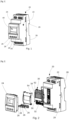
- the subject of the present application is a control device 20 for a home automation installation.
- the control device 20 comprises a housing 22 and a control device 30 arranged in the housing 22.
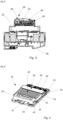
- the control device 30 comprises a printed circuit 32 provided with a ground plane, a first electronic module, namely a radiofrequency communication 34, arranged on the printed circuit 32 and comprising an antenna output 35, a second electronic module 40 arranged on the printed circuit 32 and a metallic reinforcement 50 for shielding the second electronic module 40.
- the metallic reinforcement 50 comprises a first armature element 52 electrically connected to the ground plane.
- the first armature element 52 is also electrically connected to the antenna output 35.
- the first armature element 52 being both connected to the antenna output 35 and to the ground plane of the printed circuit 32, it can both act as a shield for the electronic module 40 and form part of the antenna. allowing to transmit and receive the radiofrequency signals sent by and/or intended for the radiofrequency communication module 34.
- the control device 20 of the present application can be a digital clock controlling one or more light loads, heating and/or rolling shutters, for example.
- the control device 20 may comprise a terminal block for connection to the mains as well as, for each device intended to be controlled by the control device 20, a terminal block for connection to the device, that is to say light loads, heating, rolling shutters, for example.
- the casing 22 of the control device 20 may comprise a front face 24 from which one or more control buttons 26 can project allowing the control and/or programming of the control device 20.
- the casing 22 of the control device control 20 may comprise in the rear face 28 opposite the front face 24 a notch 29 allowing the fixing of the control device 20 to a fixing rail, such as a fixing rail commonly used in electrical panels.
- the control device 20 according to the embodiment is in a modular form and occupies a so-called width of two modules, which corresponds to approximately 36 mm in width, in the electrical panel in which it is installed.
- the first armature element 52 can mechanically connect the second electronic module 40 to the printed circuit 32.
- the first armature element 52 can comprise a central connecting part 57 which is in an essentially U-shaped form, as disclosed for example there figure 8 .
- the second electronic module 40 can be a display module, preferably a screen making it possible to display information to a user.
- the second electronic module 40 can also preferably be a liquid crystal screen.
- the front face 24 of the box 22 can be provided with a window through which the second electronic module 40 is visible to a user.
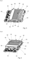
- the metallic shielding armature 50 of the second electronic module may further comprise a second armature element 54 separate and distant from the first armature element 52 and electrically connected to the ground plane.
- the first armature element 52 and the second armature element 54 can thus constitute an armature making it possible to protect the second electronic module 40 against external electromagnetic disturbances.
- the shielding formed by the metal reinforcement 50 is thus separated into at least two distinct parts, each electrically connected to the ground plane.
- the second reinforcement element 54 can also comprise a central connecting part 59.
- the second reinforcement element 54 can be distinguished from the first reinforcement element 52 essentially by the shape of its central connecting part 59.
- the central connecting part 59 of the second reinforcement element 54 can be rectangular in shape.
- the central connecting parts 57, 59 respectively of the first armature element 52 and of the second armature element 54 can be positioned between a wall of the casing 22, preferably the front wall 24 of the casing 22, and the second electronic module 40
- the central connecting parts 57, 59, in particular the central connecting part 57 of the first armature element 52 can/can be positioned close to the casing 22 and in particular close to the front wall 24 of the housing 22.
- the distance between the front wall 24 of the housing 22 can be approximately 6 millimeters. It is thus possible to bring the central connecting part 57 closer to the first armature element 52 acting as the antenna of the radio frequency communication module 34 from the outside of the casing 22, in order to increase the radio performance of the radio frequency communication module. 34.
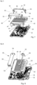
- the first reinforcement element 52 and/or the second reinforcement element 54 can/can be produced from a cut and bent sheet metal.
- the second electronic module 40 can comprise a support 42 and an electronic component 44 arranged on the support 42.
- the first reinforcing element 52 and/or the second reinforcing element 54 can be mechanically connected to the support 42, preferably by snap-fastening.
- the first armature element 52 and/or the second armature element 54 may/may comprise at least one notch 53, in which a lug 43 of the second electronic module 40 can be housed to fix the first element armature 52 to the second electronic module 40 by shape conjugation.
- the second armature element 54 may also comprise at least one notch 53, in which a lug 43 of the second electronic module 40 can be housed in order to fix the second armature element 54 to the electronic module 40 by conjugation of form.
- the lug 43 can for example be formed in the support 42.
- the notch 53 can take the form of a rectangular window formed in the first frame element 52 and/or the second frame element 54.
- the first armature element 52 and/or the second armature element 54 may/may each comprise at least one tab 55 allowing mechanical attachment to the printed circuit 32. By means of said tab 55, the first armature element 52 and/or the second armature element 54 may/may be electrically linked to the ground plane. Furthermore, the first armature element 52 can be electrically connected to the antenna output via said tongue 55.
- the radiofrequency communication module 34 can be a home automation communication module, preferably a KNX-RF communication module.
- a KNX-R F communication module allows the exchange of data by radio frequency according to a KNX communication protocol.
- the printed circuit 32 may also comprise an antenna track 33, electrically connecting the antenna output 35 to the first armature element 52.
- the antenna of the radiofrequency communication module 34 is constituted by the assembly formed by the track antenna 33 and the first armature element 52.
- the length of the antenna constituted by the assembly formed by the antenna track 33 and the first armature element 52 can be chosen according to the length of wave/frequency used for radio frequency communication. In general, antenna lengths used for radio frequency communications are proportional to the inverse of the transmit-receive frequency.
- the frequency used may for example be of the order of 868 MHz.
- the frequency used is often of the order of 2.4 GHz.
- the control apparatus 20 makes it possible to optimize the size and reduce production costs by integrating up to three functions in the frame 50, that is to say the function of fixing the second electronic module 40 to the printed circuit 32, the antenna function of the radio frequency communication module 34 and the shielding function of the second electronic module 40.
Landscapes
- Engineering & Computer Science (AREA)
- Automation & Control Theory (AREA)
- Microelectronics & Electronic Packaging (AREA)
- Shielding Devices Or Components To Electric Or Magnetic Fields (AREA)
- Selective Calling Equipment (AREA)
- Structure Of Receivers (AREA)
Claims (9)
- Steuergerät einer Haustechnikanlage, das ein Gehäuse (22) und eine in dem Gehäuse (22) eingerichtete Steuervorrichtung (30) beinhaltet, wobei die Steuervorrichtung (30) Folgendes umfasst: eine Leiterplatte (32), die über eine Erdungsebene verfügt, ein erstes elektronisches Modul, genauer gesagt ein Funkfrequenzkommunikationsmodul (34), das auf der Leiterplatte (32) eingerichtet ist und einen Antennenausgang (35) beinhaltet, ein zweites elektronisches Modul (40), das auf der Leiterplatte (32) eingerichtet ist, und einen Metallrahmen (50) zur Abschirmung des zweiten elektronischen Moduls (40), wobei der Metallrahmen (50) ein erstes Rahmenelement (52) umfasst, das elektrisch mit der Erdungsebene verbunden ist, dadurch gekennzeichnet, dass das erste Rahmenelement (52) ferner elektrisch mit dem Antennenausgang (35) verbunden ist.
- Steuergerät nach Anspruch 1, dadurch gekennzeichnet, dass das erste Rahmenelement (52) das zweite elektronische Modul (40) mechanisch mit der Leiterplatte (32) verbindet.
- Steuergerät nach einem beliebigen der Ansprüche 1 oder 2, dadurch gekennzeichnet, dass das zweite elektronische Modul (40) ein Visualisierungsmodul, vorzugsweise ein Bildschirm, ist.
- Steuergerät nach einem beliebigen der Ansprüche 1 bis 3, dadurch gekennzeichnet, dass der Metallrahmen (50) zur Abschirmung des zweiten elektronischen Moduls ferner ein zweites Rahmenelement (54) umfasst, das von dem ersten Rahmenelement (52) getrennt und beabstandet ist und elektrisch mit der Erdungsebene verbunden ist.
- Steuergerät nach einem beliebigen der Ansprüche 1 bis 4, dadurch gekennzeichnet, dass das erste Rahmenelement (52) und/oder das zweite Rahmenelement (54) aus einem gestanzten und gefalteten Blech hergestellt ist/sind.
- Steuergerät nach einem beliebigen der Ansprüche 1 bis 5, dadurch gekennzeichnet, dass das zweite elektronische Modul (40) einen Träger (42) und eine an dem Träger (42) eingerichtete elektronische Komponente (44) beinhaltet.
- Steuergerät nach Anspruch 6, dadurch gekennzeichnet, dass das erste Rahmenelement (52) und/oder das zweite Rahmenelement (54) mechanisch, vorzugsweise durch Einrasten, mit dem Träger (42) verbunden ist/sind.
- Steuergerät nach einem beliebigen der Ansprüche 1 bis 7, dadurch gekennzeichnet, dass das Funkfrequenzkommunikationsmodul (34) ein Haustechnikkommunikationsmodul, vorzugsweise ein KNX-RF-Kommunikationsmodul, ist.
- Steuergerät nach einem beliebigen der Ansprüche 1 bis 8, dadurch gekennzeichnet, dass die Leiterplatte (32) ferner eine Antennenspur (33) umfasst, die den Antennenausgang (35) elektrisch mit dem ersten Rahmenelement (52) verbindet.
Applications Claiming Priority (1)
| Application Number | Priority Date | Filing Date | Title |
|---|---|---|---|
| FR1910798A FR3101511B1 (fr) | 2019-09-30 | 2019-09-30 | Appareillage de commande d’une installation domotique |
Publications (2)
| Publication Number | Publication Date |
|---|---|
| EP3799544A1 EP3799544A1 (de) | 2021-03-31 |
| EP3799544B1 true EP3799544B1 (de) | 2023-07-19 |
Family
ID=69468718
Family Applications (1)
| Application Number | Title | Priority Date | Filing Date |
|---|---|---|---|
| EP20197366.6A Active EP3799544B1 (de) | 2019-09-30 | 2020-09-22 | Steuergeräte für haustechnikanlage |
Country Status (2)
| Country | Link |
|---|---|
| EP (1) | EP3799544B1 (de) |
| FR (1) | FR3101511B1 (de) |
Citations (1)
| Publication number | Priority date | Publication date | Assignee | Title |
|---|---|---|---|---|
| EP1398847A1 (de) * | 2002-09-12 | 2004-03-17 | Seiko Epson Corporation | Antennenanordnung, Leiterplatte, Kommunikations-Adapter und tragbares elektronisches Gerät |
Family Cites Families (5)
| Publication number | Priority date | Publication date | Assignee | Title |
|---|---|---|---|---|
| FR2826136B1 (fr) * | 2001-06-15 | 2003-11-07 | Hager Electro | Procede de programmation d'horloges programmables a cle et cle de programmation pour la mise en oeuvre de ce procede |
| US7938676B1 (en) * | 2009-10-30 | 2011-05-10 | Leviton Mfg. Co. | Receptacle with antenna |
| FR3032834B1 (fr) * | 2015-02-12 | 2018-11-09 | Legrand France | Appareil electrique, systemes comprenant un tel appareil electrique et procedes mis en œuvre dans de tels systemes |
| EP3099148B1 (de) * | 2015-05-27 | 2018-01-03 | Hager Controls SAS | Gedruckter schaltkreis, der ein gelenk umfasst |
| FR3053547B1 (fr) * | 2016-06-29 | 2019-07-19 | Hager Controls | Carte electronique |
-
2019
- 2019-09-30 FR FR1910798A patent/FR3101511B1/fr active Active
-
2020
- 2020-09-22 EP EP20197366.6A patent/EP3799544B1/de active Active
Patent Citations (1)
| Publication number | Priority date | Publication date | Assignee | Title |
|---|---|---|---|---|
| EP1398847A1 (de) * | 2002-09-12 | 2004-03-17 | Seiko Epson Corporation | Antennenanordnung, Leiterplatte, Kommunikations-Adapter und tragbares elektronisches Gerät |
Also Published As
| Publication number | Publication date |
|---|---|
| FR3101511B1 (fr) | 2021-09-03 |
| EP3799544A1 (de) | 2021-03-31 |
| FR3101511A1 (fr) | 2021-04-02 |
Similar Documents
| Publication | Publication Date | Title |
|---|---|---|
| FR2822593A1 (fr) | Antenne a plaque plate a fente, et appareil l'incorporant | |
| EP1305845A1 (de) | Planare antenne für mobilfunkgeräte | |
| EP1246298A1 (de) | Kommunikationsmultibandantenne | |
| FR2818454A1 (fr) | Protection pour reseau electrique ayant une liaison radio courte distance dite "bluetooth" | |
| EP2333912B1 (de) | Elektrische verbindungsvorrichtung | |
| EP3799544B1 (de) | Steuergeräte für haustechnikanlage | |
| FR2805669A1 (fr) | Connecteur pour circuit imprime et equipement le comportant | |
| EP0840247A1 (de) | Mit einem Speicherkartenleser versehenes Funkmodem | |
| EP2696448A1 (de) | Elektrogerät mit einem Kommunikationsmittel, das auf die Leiterplatte montiert ist | |
| WO2008125399A1 (fr) | Antenne mixte | |
| WO2018041996A1 (fr) | Appareil électronique comportant une structure d'antenne pour l'émission et/ou la réception de signaux radioélectriques et une sangle servant d'attache de l'appareil | |
| EP2404348A1 (de) | Verfahren zur herstellung einer antenne, die in einem gegebenen frequenzband betrieben wird, aus einer zweiband-antenne | |
| WO2016174115A1 (fr) | Terminal de paiement intégrant des moyens de communication sans fil | |
| WO2019122187A1 (fr) | Appareil auxiliaire pour appareillage de protection électrique | |
| EP1869727B1 (de) | Funkfrequenzvorrichtung mit orthogonale scheifenantennen | |
| WO2005088776A1 (fr) | Point d'acces a un reseau informatique | |
| EP1782398B1 (de) | Tragbare vorrichtung mit antenne und druckträgerschicht | |
| EP3479649B1 (de) | Modulare kommunikationsvorrichtung | |
| EP3512057A1 (de) | Elektrisches gerät, das drahtlos kommuniziert, und elektrischer schaltschrank, der ein solches elektrisches gerät umfasst | |
| WO2017085232A1 (fr) | Appareil electronique a emissions radio parasites limitees | |
| WO2014118445A1 (fr) | Boite d'encastrement en deux parties | |
| EP1667281A1 (de) | Mobiles Kommunikationsendgerät | |
| EP2246932B1 (de) | RF-Empfänger/Sender-Vorrichtung für ein durch ein Stromnetz gespeistes Haushaltsgerät | |
| WO2019011406A1 (fr) | Appareillage electrique et module fonctionnel additionnel associe | |
| EP0837520B1 (de) | Antennenvorrichtung zum Ausstrahlen und/oder Empfangen von Funksignalen |
Legal Events
| Date | Code | Title | Description |
|---|---|---|---|
| PUAI | Public reference made under article 153(3) epc to a published international application that has entered the european phase |
Free format text: ORIGINAL CODE: 0009012 |
|
| STAA | Information on the status of an ep patent application or granted ep patent |
Free format text: STATUS: THE APPLICATION HAS BEEN PUBLISHED |
|
| AK | Designated contracting states |
Kind code of ref document: A1 Designated state(s): AL AT BE BG CH CY CZ DE DK EE ES FI FR GB GR HR HU IE IS IT LI LT LU LV MC MK MT NL NO PL PT RO RS SE SI SK SM TR |
|
| AX | Request for extension of the european patent |
Extension state: BA ME |
|
| STAA | Information on the status of an ep patent application or granted ep patent |
Free format text: STATUS: REQUEST FOR EXAMINATION WAS MADE |
|
| 17P | Request for examination filed |
Effective date: 20210909 |
|
| RBV | Designated contracting states (corrected) |
Designated state(s): AL AT BE BG CH CY CZ DE DK EE ES FI FR GB GR HR HU IE IS IT LI LT LU LV MC MK MT NL NO PL PT RO RS SE SI SK SM TR |
|
| RIC1 | Information provided on ipc code assigned before grant |
Ipc: H05K 5/00 20060101AFI20221221BHEP |
|
| GRAP | Despatch of communication of intention to grant a patent |
Free format text: ORIGINAL CODE: EPIDOSNIGR1 |
|
| STAA | Information on the status of an ep patent application or granted ep patent |
Free format text: STATUS: GRANT OF PATENT IS INTENDED |
|
| INTG | Intention to grant announced |
Effective date: 20230214 |
|
| GRAS | Grant fee paid |
Free format text: ORIGINAL CODE: EPIDOSNIGR3 |
|
| GRAA | (expected) grant |
Free format text: ORIGINAL CODE: 0009210 |
|
| STAA | Information on the status of an ep patent application or granted ep patent |
Free format text: STATUS: THE PATENT HAS BEEN GRANTED |
|
| P01 | Opt-out of the competence of the unified patent court (upc) registered |
Effective date: 20230606 |
|
| AK | Designated contracting states |
Kind code of ref document: B1 Designated state(s): AL AT BE BG CH CY CZ DE DK EE ES FI FR GB GR HR HU IE IS IT LI LT LU LV MC MK MT NL NO PL PT RO RS SE SI SK SM TR |
|
| REG | Reference to a national code |
Ref country code: GB Ref legal event code: FG4D Free format text: NOT ENGLISH |
|
| REG | Reference to a national code |
Ref country code: CH Ref legal event code: EP |
|
| REG | Reference to a national code |
Ref country code: DE Ref legal event code: R096 Ref document number: 602020013976 Country of ref document: DE |
|
| REG | Reference to a national code |
Ref country code: IE Ref legal event code: FG4D Free format text: LANGUAGE OF EP DOCUMENT: FRENCH |
|
| REG | Reference to a national code |
Ref country code: LT Ref legal event code: MG9D |
|
| REG | Reference to a national code |
Ref country code: NL Ref legal event code: MP Effective date: 20230719 |
|
| REG | Reference to a national code |
Ref country code: AT Ref legal event code: MK05 Ref document number: 1590794 Country of ref document: AT Kind code of ref document: T Effective date: 20230719 |
|
| PG25 | Lapsed in a contracting state [announced via postgrant information from national office to epo] |
Ref country code: NL Free format text: LAPSE BECAUSE OF FAILURE TO SUBMIT A TRANSLATION OF THE DESCRIPTION OR TO PAY THE FEE WITHIN THE PRESCRIBED TIME-LIMIT Effective date: 20230719 |
|
| PG25 | Lapsed in a contracting state [announced via postgrant information from national office to epo] |
Ref country code: GR Free format text: LAPSE BECAUSE OF FAILURE TO SUBMIT A TRANSLATION OF THE DESCRIPTION OR TO PAY THE FEE WITHIN THE PRESCRIBED TIME-LIMIT Effective date: 20231020 |
|
| PG25 | Lapsed in a contracting state [announced via postgrant information from national office to epo] |
Ref country code: IS Free format text: LAPSE BECAUSE OF FAILURE TO SUBMIT A TRANSLATION OF THE DESCRIPTION OR TO PAY THE FEE WITHIN THE PRESCRIBED TIME-LIMIT Effective date: 20231119 |
|
| PG25 | Lapsed in a contracting state [announced via postgrant information from national office to epo] |
Ref country code: SE Free format text: LAPSE BECAUSE OF FAILURE TO SUBMIT A TRANSLATION OF THE DESCRIPTION OR TO PAY THE FEE WITHIN THE PRESCRIBED TIME-LIMIT Effective date: 20230719 Ref country code: RS Free format text: LAPSE BECAUSE OF FAILURE TO SUBMIT A TRANSLATION OF THE DESCRIPTION OR TO PAY THE FEE WITHIN THE PRESCRIBED TIME-LIMIT Effective date: 20230719 Ref country code: PT Free format text: LAPSE BECAUSE OF FAILURE TO SUBMIT A TRANSLATION OF THE DESCRIPTION OR TO PAY THE FEE WITHIN THE PRESCRIBED TIME-LIMIT Effective date: 20231120 Ref country code: NO Free format text: LAPSE BECAUSE OF FAILURE TO SUBMIT A TRANSLATION OF THE DESCRIPTION OR TO PAY THE FEE WITHIN THE PRESCRIBED TIME-LIMIT Effective date: 20231019 Ref country code: LV Free format text: LAPSE BECAUSE OF FAILURE TO SUBMIT A TRANSLATION OF THE DESCRIPTION OR TO PAY THE FEE WITHIN THE PRESCRIBED TIME-LIMIT Effective date: 20230719 Ref country code: LT Free format text: LAPSE BECAUSE OF FAILURE TO SUBMIT A TRANSLATION OF THE DESCRIPTION OR TO PAY THE FEE WITHIN THE PRESCRIBED TIME-LIMIT Effective date: 20230719 Ref country code: IS Free format text: LAPSE BECAUSE OF FAILURE TO SUBMIT A TRANSLATION OF THE DESCRIPTION OR TO PAY THE FEE WITHIN THE PRESCRIBED TIME-LIMIT Effective date: 20231119 Ref country code: HR Free format text: LAPSE BECAUSE OF FAILURE TO SUBMIT A TRANSLATION OF THE DESCRIPTION OR TO PAY THE FEE WITHIN THE PRESCRIBED TIME-LIMIT Effective date: 20230719 Ref country code: GR Free format text: LAPSE BECAUSE OF FAILURE TO SUBMIT A TRANSLATION OF THE DESCRIPTION OR TO PAY THE FEE WITHIN THE PRESCRIBED TIME-LIMIT Effective date: 20231020 Ref country code: FI Free format text: LAPSE BECAUSE OF FAILURE TO SUBMIT A TRANSLATION OF THE DESCRIPTION OR TO PAY THE FEE WITHIN THE PRESCRIBED TIME-LIMIT Effective date: 20230719 Ref country code: AT Free format text: LAPSE BECAUSE OF FAILURE TO SUBMIT A TRANSLATION OF THE DESCRIPTION OR TO PAY THE FEE WITHIN THE PRESCRIBED TIME-LIMIT Effective date: 20230719 |
|
| PGFP | Annual fee paid to national office [announced via postgrant information from national office to epo] |
Ref country code: FR Payment date: 20231025 Year of fee payment: 4 Ref country code: DE Payment date: 20231027 Year of fee payment: 4 Ref country code: CH Payment date: 20231031 Year of fee payment: 4 |
|
| PG25 | Lapsed in a contracting state [announced via postgrant information from national office to epo] |
Ref country code: PL Free format text: LAPSE BECAUSE OF FAILURE TO SUBMIT A TRANSLATION OF THE DESCRIPTION OR TO PAY THE FEE WITHIN THE PRESCRIBED TIME-LIMIT Effective date: 20230719 |
|
| PG25 | Lapsed in a contracting state [announced via postgrant information from national office to epo] |
Ref country code: ES Free format text: LAPSE BECAUSE OF FAILURE TO SUBMIT A TRANSLATION OF THE DESCRIPTION OR TO PAY THE FEE WITHIN THE PRESCRIBED TIME-LIMIT Effective date: 20230719 |
|
| PG25 | Lapsed in a contracting state [announced via postgrant information from national office to epo] |
Ref country code: SM Free format text: LAPSE BECAUSE OF FAILURE TO SUBMIT A TRANSLATION OF THE DESCRIPTION OR TO PAY THE FEE WITHIN THE PRESCRIBED TIME-LIMIT Effective date: 20230719 Ref country code: RO Free format text: LAPSE BECAUSE OF FAILURE TO SUBMIT A TRANSLATION OF THE DESCRIPTION OR TO PAY THE FEE WITHIN THE PRESCRIBED TIME-LIMIT Effective date: 20230719 Ref country code: ES Free format text: LAPSE BECAUSE OF FAILURE TO SUBMIT A TRANSLATION OF THE DESCRIPTION OR TO PAY THE FEE WITHIN THE PRESCRIBED TIME-LIMIT Effective date: 20230719 Ref country code: EE Free format text: LAPSE BECAUSE OF FAILURE TO SUBMIT A TRANSLATION OF THE DESCRIPTION OR TO PAY THE FEE WITHIN THE PRESCRIBED TIME-LIMIT Effective date: 20230719 Ref country code: DK Free format text: LAPSE BECAUSE OF FAILURE TO SUBMIT A TRANSLATION OF THE DESCRIPTION OR TO PAY THE FEE WITHIN THE PRESCRIBED TIME-LIMIT Effective date: 20230719 Ref country code: CZ Free format text: LAPSE BECAUSE OF FAILURE TO SUBMIT A TRANSLATION OF THE DESCRIPTION OR TO PAY THE FEE WITHIN THE PRESCRIBED TIME-LIMIT Effective date: 20230719 Ref country code: SK Free format text: LAPSE BECAUSE OF FAILURE TO SUBMIT A TRANSLATION OF THE DESCRIPTION OR TO PAY THE FEE WITHIN THE PRESCRIBED TIME-LIMIT Effective date: 20230719 |
|
| PG25 | Lapsed in a contracting state [announced via postgrant information from national office to epo] |
Ref country code: LU Free format text: LAPSE BECAUSE OF NON-PAYMENT OF DUE FEES Effective date: 20230922 |
|
| PLBE | No opposition filed within time limit |
Free format text: ORIGINAL CODE: 0009261 |
|
| STAA | Information on the status of an ep patent application or granted ep patent |
Free format text: STATUS: NO OPPOSITION FILED WITHIN TIME LIMIT |