EP3799522A1 - Verfahren und vorrichtung zur elektrischen widerstandserwärmung - Google Patents
Verfahren und vorrichtung zur elektrischen widerstandserwärmung Download PDFInfo
- Publication number
- EP3799522A1 EP3799522A1 EP20197520.8A EP20197520A EP3799522A1 EP 3799522 A1 EP3799522 A1 EP 3799522A1 EP 20197520 A EP20197520 A EP 20197520A EP 3799522 A1 EP3799522 A1 EP 3799522A1
- Authority
- EP
- European Patent Office
- Prior art keywords
- electrode
- electrodes
- flat material
- free space
- electrode arrangement
- Prior art date
- Legal status (The legal status is an assumption and is not a legal conclusion. Google has not performed a legal analysis and makes no representation as to the accuracy of the status listed.)
- Granted
Links
Images
Classifications
-
- H—ELECTRICITY
- H05—ELECTRIC TECHNIQUES NOT OTHERWISE PROVIDED FOR
- H05B—ELECTRIC HEATING; ELECTRIC LIGHT SOURCES NOT OTHERWISE PROVIDED FOR; CIRCUIT ARRANGEMENTS FOR ELECTRIC LIGHT SOURCES, IN GENERAL
- H05B3/00—Ohmic-resistance heating
- H05B3/0004—Devices wherein the heating current flows through the material to be heated
-
- B—PERFORMING OPERATIONS; TRANSPORTING
- B29—WORKING OF PLASTICS; WORKING OF SUBSTANCES IN A PLASTIC STATE IN GENERAL
- B29C—SHAPING OR JOINING OF PLASTICS; SHAPING OF MATERIAL IN A PLASTIC STATE, NOT OTHERWISE PROVIDED FOR; AFTER-TREATMENT OF THE SHAPED PRODUCTS, e.g. REPAIRING
- B29C65/00—Joining or sealing of preformed parts, e.g. welding of plastics materials; Apparatus therefor
- B29C65/02—Joining or sealing of preformed parts, e.g. welding of plastics materials; Apparatus therefor by heating, with or without pressure
- B29C65/44—Joining a heated non plastics element to a plastics element
-
- B—PERFORMING OPERATIONS; TRANSPORTING
- B29—WORKING OF PLASTICS; WORKING OF SUBSTANCES IN A PLASTIC STATE IN GENERAL
- B29C—SHAPING OR JOINING OF PLASTICS; SHAPING OF MATERIAL IN A PLASTIC STATE, NOT OTHERWISE PROVIDED FOR; AFTER-TREATMENT OF THE SHAPED PRODUCTS, e.g. REPAIRING
- B29C66/00—General aspects of processes or apparatus for joining preformed parts
- B29C66/01—General aspects dealing with the joint area or with the area to be joined
- B29C66/05—Particular design of joint configurations
- B29C66/10—Particular design of joint configurations particular design of the joint cross-sections
- B29C66/11—Joint cross-sections comprising a single joint-segment, i.e. one of the parts to be joined comprising a single joint-segment in the joint cross-section
- B29C66/112—Single lapped joints
-
- B—PERFORMING OPERATIONS; TRANSPORTING
- B29—WORKING OF PLASTICS; WORKING OF SUBSTANCES IN A PLASTIC STATE IN GENERAL
- B29C—SHAPING OR JOINING OF PLASTICS; SHAPING OF MATERIAL IN A PLASTIC STATE, NOT OTHERWISE PROVIDED FOR; AFTER-TREATMENT OF THE SHAPED PRODUCTS, e.g. REPAIRING
- B29C66/00—General aspects of processes or apparatus for joining preformed parts
- B29C66/01—General aspects dealing with the joint area or with the area to be joined
- B29C66/05—Particular design of joint configurations
- B29C66/10—Particular design of joint configurations particular design of the joint cross-sections
- B29C66/11—Joint cross-sections comprising a single joint-segment, i.e. one of the parts to be joined comprising a single joint-segment in the joint cross-section
- B29C66/114—Single butt joints
-
- B—PERFORMING OPERATIONS; TRANSPORTING
- B29—WORKING OF PLASTICS; WORKING OF SUBSTANCES IN A PLASTIC STATE IN GENERAL
- B29C—SHAPING OR JOINING OF PLASTICS; SHAPING OF MATERIAL IN A PLASTIC STATE, NOT OTHERWISE PROVIDED FOR; AFTER-TREATMENT OF THE SHAPED PRODUCTS, e.g. REPAIRING
- B29C66/00—General aspects of processes or apparatus for joining preformed parts
- B29C66/40—General aspects of joining substantially flat articles, e.g. plates, sheets or web-like materials; Making flat seams in tubular or hollow articles; Joining single elements to substantially flat surfaces
- B29C66/47—Joining single elements to sheets, plates or other substantially flat surfaces
- B29C66/474—Joining single elements to sheets, plates or other substantially flat surfaces said single elements being substantially non-flat
-
- B—PERFORMING OPERATIONS; TRANSPORTING
- B29—WORKING OF PLASTICS; WORKING OF SUBSTANCES IN A PLASTIC STATE IN GENERAL
- B29C—SHAPING OR JOINING OF PLASTICS; SHAPING OF MATERIAL IN A PLASTIC STATE, NOT OTHERWISE PROVIDED FOR; AFTER-TREATMENT OF THE SHAPED PRODUCTS, e.g. REPAIRING
- B29C66/00—General aspects of processes or apparatus for joining preformed parts
- B29C66/70—General aspects of processes or apparatus for joining preformed parts characterised by the composition, physical properties or the structure of the material of the parts to be joined; Joining with non-plastics material
- B29C66/74—Joining plastics material to non-plastics material
- B29C66/742—Joining plastics material to non-plastics material to metals or their alloys
-
- B—PERFORMING OPERATIONS; TRANSPORTING
- B29—WORKING OF PLASTICS; WORKING OF SUBSTANCES IN A PLASTIC STATE IN GENERAL
- B29C—SHAPING OR JOINING OF PLASTICS; SHAPING OF MATERIAL IN A PLASTIC STATE, NOT OTHERWISE PROVIDED FOR; AFTER-TREATMENT OF THE SHAPED PRODUCTS, e.g. REPAIRING
- B29C66/00—General aspects of processes or apparatus for joining preformed parts
- B29C66/80—General aspects of machine operations or constructions and parts thereof
-
- B—PERFORMING OPERATIONS; TRANSPORTING
- B29—WORKING OF PLASTICS; WORKING OF SUBSTANCES IN A PLASTIC STATE IN GENERAL
- B29C—SHAPING OR JOINING OF PLASTICS; SHAPING OF MATERIAL IN A PLASTIC STATE, NOT OTHERWISE PROVIDED FOR; AFTER-TREATMENT OF THE SHAPED PRODUCTS, e.g. REPAIRING
- B29C66/00—General aspects of processes or apparatus for joining preformed parts
- B29C66/90—Measuring or controlling the joining process
- B29C66/91—Measuring or controlling the joining process by measuring or controlling the temperature, the heat or the thermal flux
- B29C66/912—Measuring or controlling the joining process by measuring or controlling the temperature, the heat or the thermal flux by measuring the temperature, the heat or the thermal flux
- B29C66/9121—Measuring or controlling the joining process by measuring or controlling the temperature, the heat or the thermal flux by measuring the temperature, the heat or the thermal flux by measuring the temperature
- B29C66/91211—Measuring or controlling the joining process by measuring or controlling the temperature, the heat or the thermal flux by measuring the temperature, the heat or the thermal flux by measuring the temperature with special temperature measurement means or methods
- B29C66/91216—Measuring or controlling the joining process by measuring or controlling the temperature, the heat or the thermal flux by measuring the temperature, the heat or the thermal flux by measuring the temperature with special temperature measurement means or methods enabling contactless temperature measurements, e.g. using a pyrometer
-
- B—PERFORMING OPERATIONS; TRANSPORTING
- B29—WORKING OF PLASTICS; WORKING OF SUBSTANCES IN A PLASTIC STATE IN GENERAL
- B29C—SHAPING OR JOINING OF PLASTICS; SHAPING OF MATERIAL IN A PLASTIC STATE, NOT OTHERWISE PROVIDED FOR; AFTER-TREATMENT OF THE SHAPED PRODUCTS, e.g. REPAIRING
- B29C66/00—General aspects of processes or apparatus for joining preformed parts
- B29C66/90—Measuring or controlling the joining process
- B29C66/91—Measuring or controlling the joining process by measuring or controlling the temperature, the heat or the thermal flux
- B29C66/912—Measuring or controlling the joining process by measuring or controlling the temperature, the heat or the thermal flux by measuring the temperature, the heat or the thermal flux
- B29C66/9121—Measuring or controlling the joining process by measuring or controlling the temperature, the heat or the thermal flux by measuring the temperature, the heat or the thermal flux by measuring the temperature
- B29C66/91221—Measuring or controlling the joining process by measuring or controlling the temperature, the heat or the thermal flux by measuring the temperature, the heat or the thermal flux by measuring the temperature of the parts to be joined
-
- B—PERFORMING OPERATIONS; TRANSPORTING
- B29—WORKING OF PLASTICS; WORKING OF SUBSTANCES IN A PLASTIC STATE IN GENERAL
- B29C—SHAPING OR JOINING OF PLASTICS; SHAPING OF MATERIAL IN A PLASTIC STATE, NOT OTHERWISE PROVIDED FOR; AFTER-TREATMENT OF THE SHAPED PRODUCTS, e.g. REPAIRING
- B29C66/00—General aspects of processes or apparatus for joining preformed parts
- B29C66/90—Measuring or controlling the joining process
- B29C66/91—Measuring or controlling the joining process by measuring or controlling the temperature, the heat or the thermal flux
- B29C66/914—Measuring or controlling the joining process by measuring or controlling the temperature, the heat or the thermal flux by controlling or regulating the temperature, the heat or the thermal flux
- B29C66/9161—Measuring or controlling the joining process by measuring or controlling the temperature, the heat or the thermal flux by controlling or regulating the temperature, the heat or the thermal flux by controlling or regulating the heat or the thermal flux, i.e. the heat flux
- B29C66/91651—Measuring or controlling the joining process by measuring or controlling the temperature, the heat or the thermal flux by controlling or regulating the temperature, the heat or the thermal flux by controlling or regulating the heat or the thermal flux, i.e. the heat flux by controlling or regulating the heat generated by Joule heating or induction heating
-
- B—PERFORMING OPERATIONS; TRANSPORTING
- B29—WORKING OF PLASTICS; WORKING OF SUBSTANCES IN A PLASTIC STATE IN GENERAL
- B29C—SHAPING OR JOINING OF PLASTICS; SHAPING OF MATERIAL IN A PLASTIC STATE, NOT OTHERWISE PROVIDED FOR; AFTER-TREATMENT OF THE SHAPED PRODUCTS, e.g. REPAIRING
- B29C66/00—General aspects of processes or apparatus for joining preformed parts
- B29C66/90—Measuring or controlling the joining process
- B29C66/96—Measuring or controlling the joining process characterised by the method for implementing the controlling of the joining process
- B29C66/961—Measuring or controlling the joining process characterised by the method for implementing the controlling of the joining process involving a feedback loop mechanism, e.g. comparison with a desired value
-
- H—ELECTRICITY
- H05—ELECTRIC TECHNIQUES NOT OTHERWISE PROVIDED FOR
- H05B—ELECTRIC HEATING; ELECTRIC LIGHT SOURCES NOT OTHERWISE PROVIDED FOR; CIRCUIT ARRANGEMENTS FOR ELECTRIC LIGHT SOURCES, IN GENERAL
- H05B3/00—Ohmic-resistance heating
- H05B3/02—Details
- H05B3/03—Electrodes
-
- B—PERFORMING OPERATIONS; TRANSPORTING
- B29—WORKING OF PLASTICS; WORKING OF SUBSTANCES IN A PLASTIC STATE IN GENERAL
- B29C—SHAPING OR JOINING OF PLASTICS; SHAPING OF MATERIAL IN A PLASTIC STATE, NOT OTHERWISE PROVIDED FOR; AFTER-TREATMENT OF THE SHAPED PRODUCTS, e.g. REPAIRING
- B29C66/00—General aspects of processes or apparatus for joining preformed parts
- B29C66/90—Measuring or controlling the joining process
- B29C66/94—Measuring or controlling the joining process by measuring or controlling the time
- B29C66/949—Measuring or controlling the joining process by measuring or controlling the time characterised by specific time values or ranges
Definitions
- the invention relates to a method and a device for electrical resistance heating of an electrically conductive, flat material, in particular sheet metal, and for the thermal direct joining of a plastic component to the heated, flat material, in which a first and a second electrode are spaced apart from one another with a free space on a surface of the sheet material and an electric current is introduced into the material via the first and second electrodes to heat the material.
- a first and a second electrode are spaced apart from one another with a free space on a surface of the sheet material and an electric current is introduced into the material via the first and second electrodes to heat the material.
- a method and system for connecting components by thermal contact riveting are known.
- a rivet-like connection of two different materials for example a plastic and a sheet metal, is described, with a projection provided on the plastic material being guided through a hole during connection and then by a punch arrangement with two electrodes each having a semicircular ring of a circular arrangement is plastically heated by means of resistance heating and is deformed into a rivet head by means of a stamp-like shaft within the circular electrode in order to ensure the permanent connection of the two materials.
- the DE 30 25 875 A1 shows a device for repairing conductor track interruptions on circuit boards by micro-resistance welding with three electrodes, in which a free space in the form of a bore for a vacuum connection for sucking in a molded part is provided in the first electrode.
- Two outer electrodes which are connected to two current pulse sources, are arranged concentrically around this first electrode.
- a specific molded part for the respective interruption is punched out of foil tape, the inner electrode (first electrode) holding the punched molded part on the repair site by means of the leading inner electrode by means of suction air through the hole in this electrode.
- the trailing outer electrodes each contact the ends of the molded part, which then results in electrical resistance heating.
- the DE 10 2018 101 845 A1 describes the possibility of resistance heating of an electrically conductive surface, which is designed for a thorough connection of two layered materials by means of a fastening element provided for this purpose.
- the electrode arrangement contains two electrodes which are arranged in the shape of a half ring and insulated from one another. The fastener is then pushed through the heated surface and used to anchor the layered workpiece.
- the object of the invention is to specify, based on the known electrical resistance heating methods and devices, a method and a device for electrical resistance heating in which an electrically conductive, flat material is heated very evenly in a small limited area and at the same time the possibility of access is given to this heated area.
- planar material is heated with further electrodes, all of which are distributed in an electrode arrangement around the free space and placed on the one surface on the planar material, with different electrode configurations of the at least three electrodes alternately applied in pairs with the electric current and a plastic component is fed to the heated, flat material for thermal direct joining of this plastic component via the free space, the flat material is heated very evenly in the area of the free space in the electrode arrangement.
- three electrodes for example, exactly three different electrode constellations, namely precisely locally assigned electrode pairs, can be subjected to the electric current. This is once the area between the first and second electrodes, once again the area between the second and third electrodes and finally the area between the third and first electrodes.
- a plastic component is fed via the free space onto the heated, flat material for thermal direct joining of this plastic component thereon.
- a plastic component to be attached for example a plastic bolt
- a plastic component to be attached can be fed in parallel to the electrical resistance heating of the flat material when the optimum joining temperature is reached and attached to the flat, electrically conductive, metallic material, in particular sheet metal, in direct thermal joining. It is not necessary to remove the electrode arrangement from the sheet metal. Rather, a further electrical resistance heating can take place in parallel during the joining process in order to achieve a high-quality joint.
- the flat material can be heated very evenly in the area of the free space by the electrode arrangement according to the application, with which optimal joining temperatures for thermal direct joining of plastic components on this flat, heated material can be achieved and maintained.
- the invention is characterized in that further, electrically separated electrodes are arranged in a ring-shaped electrode arrangement around the free space, and the free space normal to the flat material allows free access to the surface of the flat material in this area.
- ring-shaped Electrode arrangement that the at least three electrodes are arranged around a center, namely a free space, the ring shape can be triangular, square, pentagonal, hexagonal, etc. or in particular have a regular polygon shape or circular or approximately circular, elliptical shape.
- a structure of the electrode arrangement that is completely rotationally symmetrical to the center point and, due to the differently controllable electrode pairs, very uniform heating in the area of the free space in the flat material can be generated by electrical resistance heating.
- the free space can also be used to monitor the temperature using appropriate sensors (for example infrared temperature sensors) so that the selected electrode constellation, their connection duration and, if applicable, their power supply are controlled and / or regulated on the basis of the measured temperatures / temperature distribution on the circular area of the free space can be.
- the current flow connection path between the two electrodes of the currently controlled electrode constellation is only heated for a relatively short period of time, so that overuse (excessive, possibly partial heating) is avoided.
- the current flow is subsequently guided over a different material area, so that overall a thermal overload of the flat material is achieved with, at the same time, very uniform heating of the surface area in question.
- the output voltage at a corresponding supply unit can also have voltages of 70 to 80 V.
- the effective voltage applied to the material surface to be heated is significantly lower.
- the electrode arrangement is pressed onto the flat material.
- the free space normal to the flat material allows free access to the flat material in this area. Due to the free access via the free space normal to the flat material, the electrical resistance heating can be monitored remotely, for example by infrared temperature sensors.
- plastic components to be attached to the flat material such as, for example, plastic bolts, can be fed precisely to the desired joining location.
- electrical resistance heating is also possible in parallel through the ring-shaped electrode arrangement. The direct thermal joining process can thus be monitored more precisely and qualitatively.
- the electrode arrangement is designed in the shape of a circular ring, with the individual electrodes being segmented and accommodated in this electrode arrangement electrically insulated from one another, an electrode arrangement that is completely rotationally symmetrical to the normal direction on the surface of the flat material is specified, which results in ideal uniform heating of the flat material in the area of the free space electrical resistance heating is possible.
- a control and supply unit is provided for the power supply of the electrode arrangement, which consists, for example, of a power converter / inverter and a downstream transformer with a rectifier unit at the output.
- the control and supply unit can also have a phase control with a downstream transformer.
- the transformer is also installed directly on the electrode arrangement and is thus part of a handling device for the electrode arrangement, for example in the form of a pistol.
- the transformer can also be arranged in a separate unit, with a correspondingly designed supply line then leading to the electrode arrangement.
- the electrode arrangement has 4 to 24 electrodes, in particular 6 to 12 electrodes
- a large number of electrode constellations can be selected by the control and supply unit designed to supply power to the electrode arrangement in order to achieve a to be able to ensure uniform heating in the area of the free space in the flat material.
- the surface temperature of the flat material is measured during the electrical resistance heating via the free access above the free space in order to be able to enable uniform heating by appropriate control loops in the event of any temperature anomalies / inequalities by changing the electrode constellation.
- each electrode is resiliently mounted in the electrode arrangement, misalignments of the electrodes or any surface shapes of the flat material, for example curved metal sheets, etc., can be compensated in such a way that each electrode essentially covers the entire surface of the flat material with the corresponding contact pressure of the entire electrode arrangement on the flat material (Sheet metal) and thus a good coupling of the Electric current allowed, in particular to avoid local overheating at the contact points due to poor electrical contact.
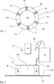
- a device for electrical resistance heating of an electrically conductive, flat material 3, here a sheet metal in a cutout, is shown in a schematic side view.
- the flat material (sheet metal) 3 has at least one freely accessible surface 31, which is shown here in FIG Fig. 2 pointing upwards.
- the electrically conductive material 3 can be inaccessible on the other side (opposite the surface 31), for example it can be covered with struts or other attached components. It is important that an area for an electrode arrangement 1 is accessible on the free surface 31, which can be loaded directly onto the surface 31 of the sheet metal 3 under a contact pressure A.
- This electrode arrangement 1 is shown in FIG Fig. 1 shown in a view that can be placed directly on the surface 31 of the metal sheet 3.
- the electrode arrangement 1 according to the embodiment shown here has six identically designed, segmented electrodes, namely a first electrode 11, a second electrode 12, a third electrode 13, a fourth electrode 14, a fifth electrode 15 and a sixth electrode 16, which are identical are arranged at a distance from one another in the form of a circular ring around a free space 18. Between the electrodes 11 to 16 there is an insulator 17 in each case electrical insulation is provided between the electrodes.
- the electrodes 11 to 16 are preferably resiliently mounted in order to compensate for any misalignments of the electrodes or unevenness or curvatures of the surface 31 of the sheet 3 and to be able to ensure a large-area contact of each individual electrode 11 to 16 on the surface 31 of the sheet 3.
- the electrode arrangement 1 is pressed either by an operator or by a machine, for example a robot or power cylinder, onto the surface 31 of the sheet metal 3 according to contact pressure A in order to achieve undesirably high contact resistances and thus at the contact points of the electrodes 11 to 16 with the surface 31 to avoid selective overheating and possible scaling.
- the device for electrical resistance heating is used for the direct joining of plastic components 4 on the electrically conductive material (sheet metal) 3.
- sheet metal electrically conductive material
- a plastic component 4 designed as a plastic bolt can be inserted in the feed direction Z into the free space 18 and thus onto the The surface 31 of the sheet 3 heated by the electrical resistance heating can be connected to the sheet 3.
- the control and supply unit 2 preferably uses current ranges between 200 A and 5000 A at a relatively low voltage of a few volts (open circuit voltage usually at 8 V, which is even lower in the process) used for a period of 0.5 to 10 seconds.
- the current flow is applied at short time intervals via an electrode constellation, for example from the first electrode 11 to the fourth electrode 14, then from the second electrode 12 to the fifth electrode 15, etc., with only neighboring electrodes or the first electrode 11 if necessary with the third electrode 13 or the fifth electrode 15 with the sixth electrode 16 is selected in order to use the respective electrode constellations (electrode pairs) for introducing the electrical current into the electrically conductive material 3.
- the electrical current introduced can be either alternating current or direct current.
- the respectively required electrode constellations (electrode wiring) and the current / time parameters can be stored in the control of the control and supply unit 2 as a predetermined recipe (welding program). Furthermore, the control and supply unit 2 can also regulate the corresponding parameters or the electrode circuitry via the temperature sensor 21 as a function of the measured temperature.
- control and supply unit 2 can control the respective electrodes 11 to 16 in a rapidly changing electrode constellation in pairs via the control and supply line 22.
- control and supply unit 2 can also regulate the heating process during the electrical Resistance heating can be carried out by executing the current flow through a suitable selection of the respective electrode constellation (electrode pairs) to which the electrical current is applied.
- the control of the current supply to the electrode pairs via a regulated or controlled current source and the sequence and assignment of the electrode pairing (different electrode constellations) can be controlled or regulated via the control and supply unit 2.
- the control and supply unit 2 can preferably contain a hardware and software-based control and regulation system with temperature-controlled regulation.
Landscapes
- Engineering & Computer Science (AREA)
- Mechanical Engineering (AREA)
- Physics & Mathematics (AREA)
- Thermal Sciences (AREA)
- Lining Or Joining Of Plastics Or The Like (AREA)
Abstract
Description
- Die Erfindung betrifft ein Verfahren und eine Vorrichtung zur elektrischen Widerstandserwärmung eines elektrisch leitfähigen, flächigen Materials, insbesondere Blech, und zum thermischen Direktfügen eines Kunststoffbauteils auf das erwärmte, flächige Material, bei dem eine erste und eine zweite Elektrode mit einem Freiraum voneinander beabstandet auf einer Oberfläche des flächigen Materials aufgesetzt werden und ein elektrischer Strom über die erste und zweite Elektrode zur Erwärmung des Materials in das Material eingeleitet wird. Derartige Verfahren und Vorrichtungen sind in unterschiedlicher Gestaltung im Stand der Technik bekannt.
- Aus der
DE 1 049 511 sind ein Verfahren und eine Vorrichtung zum Auflöten von Hartmetallplättchen bzw. Aufschweißen von Schnellstahlplättchen auf Werkzeuge durch elektrische Widerstandserwärmung bekannt. Dabei wird das räumliche Werkzeug zwischen drei Elektroden eingespannt und unter dreiphasiger Belastung eines angelegten Drehstromes erwärmt. Zwischen allen drei Elektroden steht eine regelbare Spannung, sodass durch Schalten der zwischen je zwei Elektroden fließenden Ströme die Stromverteilung im Werkzeug reguliert werden kann. - In der
DE 10 2013 011 572 A1 ist ein Verfahren zur lokalen und verzugsfreien Wärmebehandlung von Blech- oder blechartigen Bauteilen durch lokale Widerstandserwärmung beschrieben, bei dem beidseitig des zu erwärmenden Bleches zwei relativ zur Materialstärke des Bleches große Elektroden auf die beidseitig freien Oberflächen aufgepresst werden, sodass eine im Wesentlichen verzugsfreie und sehr gleichmäßige Erwärmung des Bleches im Bereich der Elektroden erreicht wird, wobei der Stromfluss senkrecht zur vom Blech aufgespannten Ebene verläuft. - Ferner ist aus der
DE 10 2016 102 846 A1 ein Verfahren sowie System zum Verbinden von Komponenten durch Wärmekontaktnieten bekannt. Dabei wird eine Niet-artige Verbindung von zwei verschiedenen Materialien, bspw. einem Kunststoff und einem Blech beschrieben, wobei ein an dem Kunststoffmaterial vorgesehener Vorsprung beim Verbinden durch ein Loch geführt und anschließend von einer Stempelanordnung mit zwei jeweils einen Halbkreisring einer kreisringförmigen Anordnung ausgebildeten zwei Elektroden mittels Widerstandserwärmen plastisch erwärmt und mittels eines stempelartigen Schaftes innerhalb der kreisringförmigen Elektrode zu einem Nietkopf verformt wird, um somit die dauerhafte Verbindung beider Materialien sicher zu stellen. - Die
DE 30 25 875 A1 zeigt eine Vorrichtung zur Reparatur von Leiterbahnunterbrechungen auf Leiterplatten durch Mikro-Widerstandsschweißen mit drei Elektroden, bei der in der ersten Elektrode ein Freiraum in Form einer Bohrung für einen Vakuumanschluss zum Ansaugen eines Formteils vorgesehen ist. Konzentrisch um diese erste Elektrode sind zwei Außenelektroden angeordnet, die mit zwei Stromimpulsquellen verbunden sind. Damit wird nun für die Reparatur einer Leiterbahnunterbrechung ein für die jeweilige Unterbrechung spezifisches Formteil aus Folienband ausgestanzt, wobei die innere Elektrode (erste Elektrode) mittels Saugluft durch die Bohrung dieser Elektrode das ausgestanzte Formteil auf der Reparaturstelle mittels der voreilenden Innenelektrode hält. Die nacheilenden Außenelektroden kontaktieren jeweils die Enden des Formteils, womit dann eine elektrische Widerstandserwärmung erfolgt. - Die
DE 10 2018 101 845 A1 beschreibt die Möglichkeit einer Widerstandserwärmung einer elektrisch leitfähigen Oberfläche, die für eine durchgreifende Verbindung zweier geschichteter Werkstoffe durch ein dafür vorgesehenes Befestigungselement ausgebildet ist. Die Elektrodenanordnung enthält dabei zwei halbringförmig angeordnete und voneinander isolierte Elektroden. Das Befestigungselement wird dann durch die erwärmte Oberfläche hindurch gedrückt und dient der Verankerung auf dem geschichteten Werkstück. - Aus der
US 4,910,376 A ist eine Schweißelektrodenanordnung mit einer inneren Elektrode und einer Mehrzahl von elektrisch miteinander verbundenen äußeren Elektroden, die eine geschlossene Form um die innere Elektrode herum festlegen, bekannt. - Aufgabe der Erfindung ist es, ausgehend von den bekannten elektrischen Widerstanderwärmungsverfahren und -vorrichtungen ein Verfahren und eine Vorrichtung zur elektrischen Widerstandserwärmung anzugeben, bei dem bzw. der ein elektrisch leitfähiges, flächiges Material in einem kleinen begrenzten Bereich sehr gleichmäßig erwärmt und gleichzeitig die Möglichkeit eines Zugriffes auf diesen erwärmten Bereich gegeben wird.
- Gelöst wird diese Aufgabe mit einem Verfahren gemäß Anspruch 1 und einer Vorrichtung gemäß Anspruch 5.
- Dadurch, dass mit weiteren Elektroden, die alle in einer Elektrodenanordnung um den Freiraum verteilt und auf der einen Oberfläche auf dem flächigen Material aufgesetzt angeordnet sind, das flächige Material erwärmt wird, wobei unterschiedliche Elektrodenkonstellationen der wenigstens drei Elektroden jeweils paarweise abwechselnd mit dem elektrischen Strom beaufschlagt werden, und über den Freiraum ein Kunststoffbauteil auf das erwärmte, flächige Material zum thermischen Direktfügen dieses Kunststoffbauteils darauf zugeführt wird, wird das flächige Material im Bereich des Freiraums in der Elektrodenanordnung sehr gleichmäßig erwärmt. Dabei können bei beispielsweise drei Elektroden genau drei verschiedene Elektrodenkonstellationen, nämlich genau örtlich zugeordnete Elektrodenpaare mit dem elektrischen Strom beaufschlagt werden. Dies ist einmal der Bereich zwischen der ersten und zweiten Elektrode, ein weiteres Mal der Bereich zwischen der zweiten und dritten Elektrode und schließlich der Bereich zwischen der dritten und ersten Elektrode. Bei vier Elektroden können insgesamt sechs Elektrodenkonstellationen aus jeweils paarweise mit elektrischem Strom beaufschlagten Elektroden von einer entsprechenden Schaltung ausgewählt werden. Dabei können bei einer umlaufend nummerierten Elektrodenanordnung zunächst die gegenüber liegenden Elektroden, also die erste Elektrode mit der dritten Elektrode sowie danach die zweite Elektrode mit der vierten Elektrode und danach Randbereiche der flächigen Materials im Freiraum durch Strombeaufschlagung der ersten Elektrode mit der zweiten Elektrode, der dritten Elektrode mit der vierten Elektrode usw. durchgeführt werden. Bei gegenüberliegenden Elektroden wird dann der Zentralbereich des beispielsweise als Kreisfläche ausgebildeten Freiraums durch den hierdurch geleiteten Stromfluss erwärmt, wohingegen bei nebeneinanderliegenden, angesteuerten Elektroden insbesondere der Randbereich erwärmt wird.
- Über den Freiraum wird ein Kunststoffbauteil auf das erwärmte, flächige Material zum thermischen Direktfügen dieses Kunststoffbauteils darauf zugeführt. Durch die Ausbildung der Elektrodenanordnung mit dem innen liegenden Freiraum kann parallel zum elektrischen Widerstandserwärmen des flächigen Materials ein aufzufügendes Kunststoffbauteil, beispielsweise ein Kunststoffbolzen gezielt bei Erreichen der optimalen Fügetemperatur zugeführt und im thermischen Direktfügen auf dem flächigen elektrisch leitfähigen, metallischen Material, insbesondere Blech aufgefügt werden. Es ist dabei nicht erforderlich, die Elektrodenanordnung vom Blech zu entfernen. Vielmehr kann während des Fügevorgangs zeitlich parallel eine weitere elektrische Widerstandserwärmung erfolgen, um eine qualitativ hochwertige Fügeverbindung zu erzielen. Insgesamt kann das flächige Material durch die anmeldungsgemäße Elektroden-Anordnung im Bereich des Freiraums sehr gleichmäßig erwärmt werden, womit optimale Fügetemperaturen zum thermischen Direktfügen von Kunststoffbauteilen auf diesem flächigen, erwärmten Material erreicht und aufrechterhalten werden.
- Entsprechend zeichnet sich die Erfindung vorrichtungsgemäß dadurch aus, dass weitere, voneinander elektrisch getrennte Elektroden in einer ringförmigen Elektrodenanordnung um den Freiraum angeordnet sind, und der Freiraum normal zum flächigen Material einen freien Zugang zur Oberfläche des flächigen Materials in diesem Bereich erlaubt. Dabei bedeutet ringförmige Elektrodenanordnung, dass die wenigstens drei Elektroden um ein Zentrum, nämlich einen Freiraum, herum angeordnet sind, dabei kann die Ringform dreieckig, viereckig, fünfeckig, sechseckig etc. sein oder insbesondere eine reguläre Polygonform oder kreisrunde oder annähernd kreisrunde, elliptische Form aufweisen. Bei einer bevorzugt kreisringförmigen oder regulär vieleckförmigen Elektrodenanordnung kann somit ein zum Mittelpunkt vollständig rotationssymmetrischer Aufbau der Elektrodenanordnung und aufgrund der verschieden ansteuerbaren Elektrodenpaare eine sehr gleichmäßige Erwärmung im Bereich des Freiraums im flächigen Material durch elektrische Widerstanderwärmung erzeugt werden. Dabei kann beispielsweise über den Freiraum auch eine Temperaturbeobachtung durch entsprechende Sensoren (beispielsweise Infrarot-Temperatursensoren) erfolgen, sodass die jeweilig ausgewählte Elektrodenkonstellation, deren Anschaltdauer sowie ggf. auch deren Stromversorgung anhand der gemessenen Temperaturen/Temperaturverteilung auf der Kreisfläche des Freiraums angesteuert und/oder geregelt werden können.
- Wenn der Wechsel zwischen verschiedenen Elektrodenkonstellationen in Zeitintervallen von 10-7 s bis 1 s, insbesondere 10-5 s bis 10-2 s durchgeführt wird, wird jeweils die Stromflussverbindungsstrecke zwischen den beiden Elektroden der gerade angesteuerten Elektrodenkonstellation nur für einen relativ kurzen Zeitraum erwärmt, sodass eine Überbeanspruchung (zu große, ggf. partielle Erhitzung) vermieden wird. Durch Umschalten auf eine andere Elektrodenkonstellation wird nachfolgend der Stromfluss über einen anderen Materialbereich geführt, sodass insgesamt eine thermische Überlastung des flächigen Materials bei gleichzeitig sehr gleichmäßiger Erwärmung des betreffenden Flächenbereichs erreicht wird.
- Wenn zum thermischen Direktfügen des Kunststoffbauteils ein elektrischer Strom von 200 A bis 5000 A bei einer niedrigen Spannung von unter 10 V für 0,5 s bis 10 s über die verschiedenen Elektrodenkonstellationen dem flächigen Material angelegt werden, wird eine schonende und gleichmäßige, aber auch intensive Erwärmung des Fügebereichs im Bereich des Freiraums im flächigen Material (Blech) erzielt, der genau auf die Verwendung beim thermischen Direktfügen von Kunststoffbauteilen ausgerichtet ist.
- Selbstverständlich kann bei sehr kurzen Impulsen auch ein deutlich höherer Strom fließen, wie beispielsweise 10.000 A oder mehr. Ferner ist es auch möglich, dass die Ausgangsspannung an einer entsprechenden Versorgungseinheit auch Spannungen von 70 bis 80 V aufweisen kann. Dabei ist die an der zu erwärmenden Materialoberfläche anliegende effektive Spannung jedoch deutlich niedriger.
- Um den elektrischen Kontakt der Elektroden auf dem flächigen Element (Blech) zu gewährleisten, wird die Elektrodenanordnung auf dem flächigen Material aufgepresst.
- Dabei erlaubt der Freiraum normal zum flächigen Material einen freien Zugang zum flächigen Material in diesem Bereich. Durch den freien Zugang über den Freiraum normal zum flächigen Material kann die elektrische Widerstanderwärmung beispielsweise durch Infrarot-Temperatursensoren quasi aus der Ferne überwacht werden. Darüber hinaus ist es möglich, dass auf das flächige Material aufzufügende Kunststoffbauteile, wie beispielsweise Kunststoffbolzen präzise dem gewünschten Fügeort zugeführt werden können. Dabei ist parallel durch die ringförmige Elektrodenanordnung weiterhin eine elektrische Widerstandserwärmung möglich. Der thermische Direktfügevorgang wird somit präziser und qualitativ überwachbar.
- Wenn die Elektrodenanordnung kreisringförmig ausgebildet ist, wobei die einzelnen Elektroden segmentiert und voneinander elektrisch isoliert in dieser Elektrodenanordnung aufgenommen sind, wird eine zur Normalrichtung auf die Oberfläche des flächigen Materials vollständig rotationssymmetrische Elektrodenanordnung angegeben, womit eine ideal gleichförmige Erwärmung des flächigen Materials im Bereich des Freiraums durch die elektrische Widerstandserwärmung möglich ist.
- Für die Stromversorgung der Elektrodenanordnung ist eine Steuer- und Versorgungseinheit vorgesehen, die beispielweise aus einem Stromumrichter/ Inverter und einem nachgeschalteten Transformator mit Gleichrichtereinheit am Ausgang besteht. Alternativ kann die Steuer- und Versorgungseinheit auch eine Phasenanschnittssteuerung mit nachgeschaltetem Trafo aufweisen. Dabei ist es möglich, dass der Trafo auch direkt an der Elektrodenanordnung verbaut ist und somit Bestandteil einer Handhabungsvorrichtung für die Elektrodenanordnung, beispielweise in Pistolenform, ist. Alternativ kann der Trafo auch in einer gesonderten Einheit angeordnet sein, wobei dann eine entsprechend ausgelegte Versorgungsleitung zur Elektrodenanordnung führt.
- Dadurch, dass die Elektrodenanordnung 4 bis 24 Elektroden, insbesondere 6 bis 12 Elektroden aufweist, können eine Vielzahl von Elektrodenkonstellationen durch die zur Stromversorgung der Elektrodenanordnung ausgelegte Steuer- und Versorgungseinheit gewählt werden, um auch bei komplizierten Bauteilen, ggf. mit asymmetrisch vorhandenen Temperatursenken, eine gleichmäßige Erwärmung im Bereich des Freiraums im flächigen Material sicherstellen zu können. In besonders bevorzugter Ausbildung wird während der elektrischen Widerstandserwärmung über den freien Zugang oberhalb des Freiraums die Oberflächentemperatur des flächigen Materials gemessen, um bei etwaigen Temperaturanomalien/-ungleichheiten durch Verändern der Elektrodenkonstellation eine gleichmäßige Erwärmung durch entsprechende Regelkreise ermöglichen zu können.
- Wenn die Elektroden in der Elektrodenanordnung federnd gelagert sind, können Fehlstellungen der Elektroden oder etwaige Oberflächenformen des flächigen Materials, beispielsweise gewölbte Bleche etc. so ausgeglichen werden, dass jede Elektrode bei entsprechendem Anpressdruck der gesamten Elektrodenanordnung auf das flächige Material im Wesentlichen vollflächig auf dem flächigen Material (Blech) aufliegt und somit eine gute Ankopplung des elektrischen Stromes erlaubt, um insbesondere ein lokales Überhitzen an den Kontaktstellen durch zu schlechten elektrischen Kontakt vermeiden zu können.
- Nachfolgend wird ein Ausführungsbeispiel anhand der beiliegenden Zeichnungen ausführlich erläutert.
- Darin zeigt:
- Fig. 1
- eine Ansicht auf eine Elektrodenanordnung und
- Fig. 2
- eine Vorrichtung zur elektrischen Widerstandserwärmung mit der in
Fig. 1 dargestellten Elektrodenanordnung in schematischer Seitenansicht. - In
Fig. 2 ist in schematischer Seitenansicht eine Vorrichtung zur elektrischen Widerstandserwärmung eines elektrisch leitfähigen, flächigen Materials 3, hier ein Blech in einem Ausschnitt, dargestellt. Das flächige Material (Blech) 3 weist wenigstens eine frei zugängliche Oberfläche 31 auf, die hier inFig. 2 nach oben zeigt. Das elektrisch leitfähige Material 3 kann auf der anderen Seite (gegenüberliegend der Oberfläche 31) unzugänglich sein, beispielsweise mit Verstrebungen oder sonstigen angesetzten Bauteilen belegt sein. Wichtig ist, dass an der freien Oberfläche 31 ein Bereich für eine Elektrodenanordnung 1 zugänglich ist, die unmittelbar auf die Oberfläche 31 des Bleches 3 unter einem Anpressdruck A aufgelastet werden kann. - Diese Elektrodenanordnung 1 ist in
Fig. 1 in einer Ansicht dargestellt, die unmittelbar auf die Oberfläche 31 des Bleches 3 aufsetzbar ist. Die Elektrodenanordnung 1 gemäß dem hier dargestellten Ausführungsbeispiel weist sechs gleichartig ausgebildete, segmentierte Elektroden, nämlich eine erste Elektrode 11, eine zweite Elektrode 12, eine dritte Elektrode 13, eine vierte Elektrode 14, eine fünfte Elektrode 15 und eine sechste Elektrode 16 auf, die gleich beabstandet voneinander in Kreisringform um einen Freiraum 18 angeordnet sind. Zwischen den Elektroden 11 bis 16 ist jeweils ein Isolator 17 zur elektrischen Isolierung zwischen den Elektroden vorgesehen. Die Elektroden 11 bis 16 sind bevorzugt federnd gelagert, um etwaige Fehlstellungen der Elektroden bzw. Unebenheiten oder Wölbungen der Oberfläche 31 des Bleches 3 ausgleichen und dabei eine großflächige Kontaktierung jeder einzelnen Elektrode 11 bis 16 auf der Oberfläche 31 des Bleches 3 sicherstellen zu können. - Die Elektrodenanordnung 1 wird dabei entweder von einem Bediener oder von einer Maschine, beispielsweise einem Roboter oder Kraftzylinder, auf die Oberfläche 31 des Bleches 3 entsprechend Anpressdruck A angepresst, um an den Kontaktstellen der Elektroden 11 bis 16 mit der Oberfläche 31 unerwünscht hohe Übergangswiderstände und somit punktuelle Überhitzungen und etwaige Verzunderungen zu vermeiden.
- Die Elektrodenanordnung 1 ist dabei von einer Steuer- und Versorgungseinheit 2 über eine Steuer- und Versorgungsleitung 22 versorgt und angesteuert. Dabei ist jede der Elektroden 11 bis 16 einzeln von der Steuer- und Versorgungseinheit 2 auswählbar, um für die jeweils durchzuführende elektrische Widerstandserwärmung eine optimale Wärmeverteilung im Bereich des Freiraums 18 der Elektrodenanordnung 1 im elektrisch leitfähigen Material (Blech) 3 zu ermöglichen. Ferner ist es bevorzugt, dass die Steuer- und Versorgungseinheit 2 mit einem Temperatursensor 21 wirkverbunden ist, der die Temperatur der im Freiraum 18 freilegenden Kreisfläche der Oberfläche 31 des Bleches 3 erlaubt. Dieser Temperatursensor 21 ist beispielsweise ein Infrarot-Sensor, der die Temperatur an der Oberfläche 31 in diesem Bereich berührungslos messen kann.
- In weiterer Ausbildung der Erfindung wird die Vorrichtung zur elektrischen Widerstandserwärmung zum Direktfügen von Kunststoffbauteilen 4 auf dem elektrisch leitfähigen Material (Blech) 3 verwendet. Mit diesem thermischen Direktfügen kann beispielsweise, ein als Kunststoffbolzen ausgebildetes Kunststoffbauteil 4 in Zufuhrrichtung Z in den Freiraum 18 und somit auf die durch die elektrische Widerstandserwärmung erwärmte Oberfläche 31 des Bleches 3 mit dem Blech 3 verbunden werden.
- Für dieses thermische Direktfügen von Kunststoffbauteilen 4 auf metallischen Blechen 3 werden von der Steuer- und Versorgungeinheit 2 bevorzugt Strombereiche zwischen 200 A und 5000 A bei einer relativ niedrigen Spannung von wenigen Volt (Leerlaufspannung meist bei 8 V, die im Prozess noch geringer ist) über einen Zeitraum von 0,5 bis 10 s verwendet. Dabei wird jedoch der Stromfluss in kurzen Zeitintervallen jeweils über eine Elektrodenkonstellation, beispielsweise von der ersten Elektrode 11 zur vierten Elektrode 14, dann von der zweiten Elektrode 12 zur fünften Elektrode 15 usw. angelegt, wobei auch bei Bedarf nur benachbarte Elektroden oder die erste Elektrode 11 mit der dritten Elektrode 13 oder die fünfte Elektrode 15 mit der sechsten Elektrode 16 ausgewählt, um die jeweiligen Elektrodenkonstellationen (Elektrodenpaare) zur Einleitung des elektrischen Stromes in das elektrisch leitfähige Material 3 zu verwenden. Dabei kann der eingeleitete elektrische Strom sowohl Wechselstrom, wie auch Gleichstrom sein.
- Die jeweilig erforderlichen Elektrodenkonstellationen (Elektrodenbeschaltung) sowie die Strom-/Zeitparameter können in der Steuerung der Steuer- und Versorgungseinheit 2 als vorgegebenes Rezept (Schweißprogramm) hinterlegt sein. Ferner kann auch abhängig von der gemessenen Temperatur über den Temperatursensor 21 eine Regelung der entsprechenden Parameter bzw. der Elektrodenbeschaltung durch die Steuer- und Versorgungseinheit 2 erreicht werden.
- Im Zusammenhang mit der Temperaturmessung durch den Temperatursensor 21 kann somit die Steuer- und Versorgungseinheit 2 über die Steuer- und Versorgungsleitung 22 die jeweiligen Elektroden 11 bis 16 in einer jeweilig schnell wechselnden Elektrodenkonstellation paarweise ansteuern. Durch die Temperaturüberwachung kann in die Steuer- und Versorgungseinheit 2 auch eine Regelung des Erwärmungsvorganges während der elektrischen Widerstandserwärmung durchgeführt werden, in dem der Stromfluss durch eine geeignete Auswahl der jeweils angesprochenen Elektrodenkonstellation (Elektrodenpaare), die mit dem elektrischen Strom beaufschlagt sind, ausgeführt werden. Somit kann über die Steuer- und Versorgungseinheit 2 die Steuerung der Bestromung der Elektrodenpaare über eine geregelte bzw. gesteuerte Stromquelle sowie die Reihenfolge und die Zuordnung der Elektrodenpaarung (unterschiedlicher Elektrodenkonstellationen) gesteuert bzw. geregelt werden. Bevorzugt kann die Steuer- und Versorgungseinheit 2 eine Hard- und Software basiertes Steuerungs- und Regelungssystem mit temperaturgeführter Regelung enthalten.
- Um eine qualitative Aussage über den Prozess des thermischen Direktfügens eines Kunststoffbauteils 4, beispielsweise Kunststoffbolzens, auf einem metallischen Blechbauteil treffen zu können, kann der jeweils aufgewendete Stromfluss, die Anpresskraft und die erreichten Temperaturen aufgezeichnet und für eine spätere Dokumentation des Fügeprozesses zur Verfügung stehen.
-
- 1
- Elektrodenanordnung
- 11
- erste Elektrode
- 12
- zweite Elektrode
- 13
- dritte Elektrode
- 14
- vierte Elektrode
- 15
- fünfte Elektrode
- 16
- sechste Elektrode
- 17
- Isolator
- 18
- Freiraum
- 2
- Steuer- und Versorgungseinheit
- 21
- Temperatursensor
- 22
- Steuer- und Versorgungsleitung
- 3
- elektrisch leitfähiges Material, Blech
- 31
- Oberfläche
- 4
- Kunststoffbauteil
- A
- Anpressdruck
- Z
- Zufuhrrichtung
Claims (8)
- Verfahren zur elektrischen Widerstandserwärmung eines elektrisch leitfähigen, flächigen Materials (3), insbesondere Blech, und zum thermischen Direktfügen eines Kunststoffbauteils (4) auf das erwärmte, flächige Material (3), bei dem eine erste und eine zweite Elektrode (11, 12) mit einem Freiraum (18) voneinander beabstandet auf einer Oberfläche (31) des flächigen Materials (3) aufgesetzt werden und ein elektrischer Strom über die erste und zweite Elektrode (11, 12) zur Erwärmung des Materials (3) in das Material eingeleitet wird, dadurch gekennzeichnet, dass mit weiteren Elektroden (13, 14, 15, 16), die alle in einer Elektrodenanordnung (1) um den Freiraum (18) verteilt und auf der einen Oberfläche (31) auf dem flächigen Material (3) aufgesetzt angeordnet sind, das flächige Material (3) erwärmt wird, wobei unterschiedliche Elektrodenkonstellationen der wenigstens drei Elektroden (11, 12, 13, 14, 15, 16) jeweils paarweise abwechselnd mit dem elektrischen Strom beaufschlagt werden, und über den Freiraum (18) das Kunststoffbauteil (4) auf das erwärmte, flächige Material (3) zum thermischen Direktfügen dieses Kunststoffbauteils (4) darauf zugeführt wird.
- Verfahren nach Anspruch 1, dadurch gekennzeichnet, dass der Wechsel zwischen verschiedenen Elektrodenkonstellationen in Zeitintervallen von 10-7 s bis 1 s, insbesondere 10-5 s bis 10-2 s durchgeführt wird.
- Verfahren nach Anspruch 1 oder 2, dadurch gekennzeichnet, dass zum thermischen Direktfügen des Kunststoffbauteils (4) ein elektrischer Strom von 200 A bis 5000 A bei einer niedrigen Spannung von unter 10 V für 0,5 s bis 10 s über die verschiedenen Elektrodenkonstellationen dem flächigen Material (3) angelegt werden.
- Verfahren nach einem der vorangehenden Ansprüche, dadurch gekennzeichnet, dass die Elektrodenanordnung (1) auf dem flächigen Material (3) aufgepresst wird.
- Vorrichtung zur elektrischen Widerstandserwärmung eines elektrisch leitfähigen, flächigen Materials (3), insbesondere Blech, bei dem eine erste und eine zweite Elektrode (11, 12) mit einem Freiraum (18) voneinander beabstandet zum Aufsetzen auf einer Oberfläche (31) des flächigen Materials (3) vorgesehen sind und ein elektrischer Strom von einer Steuer- und Versorgungseinheit (2) über die erste und zweite Elektrode (11, 12) zur Erwärmung des Materials in das Material (3) eingeleitet wird, dadurch gekennzeichnet, dass weitere, voneinander elektrisch getrennte Elektroden (13, 14, 15, 16) in einer ringförmigen Elektrodenanordnung (1) um den Freiraum (18) angeordnet sind, und der Freiraum (18) normal zum flächigen Material (3) einen freien Zugang zur Oberfläche (31) des flächigen Materials (3) in diesem Bereich erlaubt.
- Vorrichtung nach Anspruch 5, dadurch gekennzeichnet, dass die Elektrodenanordnung (1) kreisringförmig ausgebildet ist, wobei die einzelnen Elektroden (11, 12, 13, 14, 15, 16) segmentiert und voneinander elektrisch isoliert mit Isolatoren (17) in dieser Elektrodenanordnung (1) aufgenommen sind.
- Vorrichtung nach Anspruch 5 oder 6, dadurch gekennzeichnet, dass die Elektrodenanordnung (1) 4 bis 24 Elektroden (11, 12, 13, 14, 15, 16), insbesondere 6 bis 12 Elektroden aufweist.
- Vorrichtung nach Anspruch 5, 6 oder 7, dadurch gekennzeichnet, dass die Elektroden (11, 12, 13, 14, 15, 16) in der Elektrodenanordnung (1) federnd gelagert sind.
Applications Claiming Priority (1)
| Application Number | Priority Date | Filing Date | Title |
|---|---|---|---|
| DE102019126027.2A DE102019126027A1 (de) | 2019-09-26 | 2019-09-26 | Verfahren und Vorrichtung zur elektrischen Widerstandserwärmung |
Publications (3)
| Publication Number | Publication Date |
|---|---|
| EP3799522A1 true EP3799522A1 (de) | 2021-03-31 |
| EP3799522C0 EP3799522C0 (de) | 2025-05-14 |
| EP3799522B1 EP3799522B1 (de) | 2025-05-14 |
Family
ID=72615621
Family Applications (1)
| Application Number | Title | Priority Date | Filing Date |
|---|---|---|---|
| EP20197520.8A Active EP3799522B1 (de) | 2019-09-26 | 2020-09-22 | Verfahren und vorrichtung zur elektrischen widerstandserwärmung |
Country Status (2)
| Country | Link |
|---|---|
| EP (1) | EP3799522B1 (de) |
| DE (1) | DE102019126027A1 (de) |
Citations (8)
| Publication number | Priority date | Publication date | Assignee | Title |
|---|---|---|---|---|
| DE1049511B (de) | 1959-01-29 | Lippstadt Clemens Jungeblodt | Verfahren und Vorrichtung zum Auflöten von Hartmetallplättchen bzw. Aufschweißen von Schnellstahlplättchen u. dgl. auf Werkzeuge, insbesondere Stahlhalter, durch elektrische Widerstandserwärmung | |
| DE3025875A1 (de) | 1980-07-08 | 1982-02-04 | Siemens AG, 1000 Berlin und 8000 München | Vorrichtung zur reparatur von leiterbahnunterbrechungen |
| EP0343375A1 (de) * | 1988-05-26 | 1989-11-29 | Siemens Aktiengesellschaft | Verfahren zur Reparatur von Leiterbahnunterbrechungen |
| US4910376A (en) | 1986-09-30 | 1990-03-20 | Chloride Silent Power, Ltd. | Welding electrode arrangement |
| US6459064B1 (en) * | 1997-08-14 | 2002-10-01 | Magna IHV Gesellschaft fur Innenhochdruck—Verfahren mbH | Assembling electroconductive parts by electric current heating |
| DE102013011572A1 (de) | 2013-07-10 | 2015-01-15 | Audi Ag | Verfahren zur lokalen und verzugsfreien Wärmebehandlung von Blech- oder blechartigen Bauteilen durch lokale Widerstandserwärmung |
| DE102016102846A1 (de) | 2015-02-28 | 2016-09-01 | GM Global Technology Operations LLC (n. d. Ges. d. Staates Delaware) | Systeme und Verfahren zum Verbinden von Komponenten durch Wärmekontaktnieten |
| DE102018101845A1 (de) | 2017-01-30 | 2018-08-02 | GM Global Technology Operations LLC | Blindfluss-Schraubverbindung von Materialien |
-
2019
- 2019-09-26 DE DE102019126027.2A patent/DE102019126027A1/de not_active Ceased
-
2020
- 2020-09-22 EP EP20197520.8A patent/EP3799522B1/de active Active
Patent Citations (8)
| Publication number | Priority date | Publication date | Assignee | Title |
|---|---|---|---|---|
| DE1049511B (de) | 1959-01-29 | Lippstadt Clemens Jungeblodt | Verfahren und Vorrichtung zum Auflöten von Hartmetallplättchen bzw. Aufschweißen von Schnellstahlplättchen u. dgl. auf Werkzeuge, insbesondere Stahlhalter, durch elektrische Widerstandserwärmung | |
| DE3025875A1 (de) | 1980-07-08 | 1982-02-04 | Siemens AG, 1000 Berlin und 8000 München | Vorrichtung zur reparatur von leiterbahnunterbrechungen |
| US4910376A (en) | 1986-09-30 | 1990-03-20 | Chloride Silent Power, Ltd. | Welding electrode arrangement |
| EP0343375A1 (de) * | 1988-05-26 | 1989-11-29 | Siemens Aktiengesellschaft | Verfahren zur Reparatur von Leiterbahnunterbrechungen |
| US6459064B1 (en) * | 1997-08-14 | 2002-10-01 | Magna IHV Gesellschaft fur Innenhochdruck—Verfahren mbH | Assembling electroconductive parts by electric current heating |
| DE102013011572A1 (de) | 2013-07-10 | 2015-01-15 | Audi Ag | Verfahren zur lokalen und verzugsfreien Wärmebehandlung von Blech- oder blechartigen Bauteilen durch lokale Widerstandserwärmung |
| DE102016102846A1 (de) | 2015-02-28 | 2016-09-01 | GM Global Technology Operations LLC (n. d. Ges. d. Staates Delaware) | Systeme und Verfahren zum Verbinden von Komponenten durch Wärmekontaktnieten |
| DE102018101845A1 (de) | 2017-01-30 | 2018-08-02 | GM Global Technology Operations LLC | Blindfluss-Schraubverbindung von Materialien |
Also Published As
| Publication number | Publication date |
|---|---|
| DE102019126027A1 (de) | 2021-04-01 |
| EP3799522C0 (de) | 2025-05-14 |
| EP3799522B1 (de) | 2025-05-14 |
Similar Documents
| Publication | Publication Date | Title |
|---|---|---|
| EP3710234B1 (de) | Vorrichtung zum thermischen verschweissen von kunststoffteilen sowie anordnung enthaltend eine solche vorrichtung | |
| EP2859987A1 (de) | Bauteilverbund | |
| DE102013011572A1 (de) | Verfahren zur lokalen und verzugsfreien Wärmebehandlung von Blech- oder blechartigen Bauteilen durch lokale Widerstandserwärmung | |
| DE102014204400A1 (de) | Verfahren zur einseitigen Widerstandsschweißung | |
| DE112011105617T5 (de) | Elektrische Heizvorrichtung | |
| EP2632626A2 (de) | FÜGEN EINES ERSTEN BAUTEILS MIT EINEM ZWEITEN BAUTEIL MITTELS EINES EINSEITIGEN WIDERSTANDSPUNKTSCHWEIßENS | |
| DE102011004229A1 (de) | Dehnungsvorrichtung für Stromschienen in Niederspannungs-Schienensystemen zur Verteilung elektrischer Energie und Schienenkasten mit einer solchen Dehnungs-vorrichtung | |
| EP3108019B1 (de) | Verfahren zum paarweisen konduktiven erwärmen von blechen und erwärmungseinrichtung dafür | |
| EP3799522B1 (de) | Verfahren und vorrichtung zur elektrischen widerstandserwärmung | |
| DE102014115145A1 (de) | Verfahren und Vorrichtung zum optimierten Widerstandsschweißen von Blechen | |
| DE102019108813B4 (de) | Verfahren zum mechanischen Fügen | |
| DE102017217318A1 (de) | Ladevorrichtung und Ladeverfahren für eine Batteriezelle | |
| DE102011018653A1 (de) | Widerstands-Schweißvorrichtung | |
| EP0001557B1 (de) | Verfahren zum Trennen eines eine Vielzahl von Drähten aufweisenden Seiles | |
| EP2940321B1 (de) | Vorrichtung zum aushärten eines elektrisch leitenden klebstoffes | |
| DE102016118517B3 (de) | Verfahren und Vorrichtung zum elektrischen Verbinden von zwei metallischen Leitern | |
| EP1819849A1 (de) | Verfahren zum überwachen eines elektrochemischen behandlungsprozesses und für dieses verfahren geeignete elektrodenanordnung | |
| EP3760360B1 (de) | Schweisssteuerung für ein schweisswerkzeug und verfahren zum vermeiden von kraftschwingungen eines schweisswerkzeugs | |
| EP2838314B1 (de) | Wärmestrahler, Vorrichtung zum Infrarotschweißen und Verfahren zum Erwärmen von Kunststoffbauteilen | |
| DE202004019313U1 (de) | Schweißeinrichtung zum Impulsschweißen von Werkstücken | |
| DE10353478B3 (de) | Verfahren und Vorrichtung zum Überprüfen einer Elektrodenkraft einer Schweißzange | |
| DE102018104701A1 (de) | Verfahren zur mechanischen Verbindung und Vorrichtung zur Durchführung des Verfahrens | |
| DE3542741C2 (de) | ||
| DE3222691A1 (de) | Lichtbogenheizgeraet | |
| AT500682B1 (de) | Verfahren und vorrichtung zum erwärmen von elektrisch leitfähigen unbeschichteten oder beschichteten platinen |
Legal Events
| Date | Code | Title | Description |
|---|---|---|---|
| PUAI | Public reference made under article 153(3) epc to a published international application that has entered the european phase |
Free format text: ORIGINAL CODE: 0009012 |
|
| STAA | Information on the status of an ep patent application or granted ep patent |
Free format text: STATUS: THE APPLICATION HAS BEEN PUBLISHED |
|
| AK | Designated contracting states |
Kind code of ref document: A1 Designated state(s): AL AT BE BG CH CY CZ DE DK EE ES FI FR GB GR HR HU IE IS IT LI LT LU LV MC MK MT NL NO PL PT RO RS SE SI SK SM TR |
|
| AX | Request for extension of the european patent |
Extension state: BA ME |
|
| STAA | Information on the status of an ep patent application or granted ep patent |
Free format text: STATUS: REQUEST FOR EXAMINATION WAS MADE |
|
| 17P | Request for examination filed |
Effective date: 20210908 |
|
| RBV | Designated contracting states (corrected) |
Designated state(s): AL AT BE BG CH CY CZ DE DK EE ES FI FR GB GR HR HU IE IS IT LI LT LU LV MC MK MT NL NO PL PT RO RS SE SI SK SM TR |
|
| GRAP | Despatch of communication of intention to grant a patent |
Free format text: ORIGINAL CODE: EPIDOSNIGR1 |
|
| STAA | Information on the status of an ep patent application or granted ep patent |
Free format text: STATUS: GRANT OF PATENT IS INTENDED |
|
| RIC1 | Information provided on ipc code assigned before grant |
Ipc: B29C 65/00 20060101ALI20250122BHEP Ipc: H05B 3/03 20060101ALI20250122BHEP Ipc: H05B 3/00 20060101AFI20250122BHEP |
|
| INTG | Intention to grant announced |
Effective date: 20250130 |
|
| GRAS | Grant fee paid |
Free format text: ORIGINAL CODE: EPIDOSNIGR3 |
|
| GRAA | (expected) grant |
Free format text: ORIGINAL CODE: 0009210 |
|
| STAA | Information on the status of an ep patent application or granted ep patent |
Free format text: STATUS: THE PATENT HAS BEEN GRANTED |
|
| AK | Designated contracting states |
Kind code of ref document: B1 Designated state(s): AL AT BE BG CH CY CZ DE DK EE ES FI FR GB GR HR HU IE IS IT LI LT LU LV MC MK MT NL NO PL PT RO RS SE SI SK SM TR |
|
| REG | Reference to a national code |
Ref country code: GB Ref legal event code: FG4D Free format text: NOT ENGLISH |
|
| REG | Reference to a national code |
Ref country code: CH Ref legal event code: EP |
|
| REG | Reference to a national code |
Ref country code: DE Ref legal event code: R096 Ref document number: 502020011046 Country of ref document: DE |
|
| REG | Reference to a national code |
Ref country code: IE Ref legal event code: FG4D Free format text: LANGUAGE OF EP DOCUMENT: GERMAN |
|
| U01 | Request for unitary effect filed |
Effective date: 20250514 |
|
| U07 | Unitary effect registered |
Designated state(s): AT BE BG DE DK EE FI FR IT LT LU LV MT NL PT RO SE SI Effective date: 20250520 |
|
| PG25 | Lapsed in a contracting state [announced via postgrant information from national office to epo] |
Ref country code: ES Free format text: LAPSE BECAUSE OF FAILURE TO SUBMIT A TRANSLATION OF THE DESCRIPTION OR TO PAY THE FEE WITHIN THE PRESCRIBED TIME-LIMIT Effective date: 20250514 |
|
| PG25 | Lapsed in a contracting state [announced via postgrant information from national office to epo] |
Ref country code: NO Free format text: LAPSE BECAUSE OF FAILURE TO SUBMIT A TRANSLATION OF THE DESCRIPTION OR TO PAY THE FEE WITHIN THE PRESCRIBED TIME-LIMIT Effective date: 20250814 Ref country code: GR Free format text: LAPSE BECAUSE OF FAILURE TO SUBMIT A TRANSLATION OF THE DESCRIPTION OR TO PAY THE FEE WITHIN THE PRESCRIBED TIME-LIMIT Effective date: 20250815 |
|
| PG25 | Lapsed in a contracting state [announced via postgrant information from national office to epo] |
Ref country code: PL Free format text: LAPSE BECAUSE OF FAILURE TO SUBMIT A TRANSLATION OF THE DESCRIPTION OR TO PAY THE FEE WITHIN THE PRESCRIBED TIME-LIMIT Effective date: 20250514 |
|
| PG25 | Lapsed in a contracting state [announced via postgrant information from national office to epo] |
Ref country code: HR Free format text: LAPSE BECAUSE OF FAILURE TO SUBMIT A TRANSLATION OF THE DESCRIPTION OR TO PAY THE FEE WITHIN THE PRESCRIBED TIME-LIMIT Effective date: 20250514 |
|
| PG25 | Lapsed in a contracting state [announced via postgrant information from national office to epo] |
Ref country code: RS Free format text: LAPSE BECAUSE OF FAILURE TO SUBMIT A TRANSLATION OF THE DESCRIPTION OR TO PAY THE FEE WITHIN THE PRESCRIBED TIME-LIMIT Effective date: 20250814 |
|
| PG25 | Lapsed in a contracting state [announced via postgrant information from national office to epo] |
Ref country code: IS Free format text: LAPSE BECAUSE OF FAILURE TO SUBMIT A TRANSLATION OF THE DESCRIPTION OR TO PAY THE FEE WITHIN THE PRESCRIBED TIME-LIMIT Effective date: 20250914 |
|
| U20 | Renewal fee for the european patent with unitary effect paid |
Year of fee payment: 6 Effective date: 20250923 |
|
| PGFP | Annual fee paid to national office [announced via postgrant information from national office to epo] |
Ref country code: GB Payment date: 20251031 Year of fee payment: 6 |
|
| PG25 | Lapsed in a contracting state [announced via postgrant information from national office to epo] |
Ref country code: SM Free format text: LAPSE BECAUSE OF FAILURE TO SUBMIT A TRANSLATION OF THE DESCRIPTION OR TO PAY THE FEE WITHIN THE PRESCRIBED TIME-LIMIT Effective date: 20250514 |
|
| PG25 | Lapsed in a contracting state [announced via postgrant information from national office to epo] |
Ref country code: CZ Free format text: LAPSE BECAUSE OF FAILURE TO SUBMIT A TRANSLATION OF THE DESCRIPTION OR TO PAY THE FEE WITHIN THE PRESCRIBED TIME-LIMIT Effective date: 20250514 |
|
| PG25 | Lapsed in a contracting state [announced via postgrant information from national office to epo] |
Ref country code: SK Free format text: LAPSE BECAUSE OF FAILURE TO SUBMIT A TRANSLATION OF THE DESCRIPTION OR TO PAY THE FEE WITHIN THE PRESCRIBED TIME-LIMIT Effective date: 20250514 |
|
| PLBE | No opposition filed within time limit |
Free format text: ORIGINAL CODE: 0009261 |
|
| STAA | Information on the status of an ep patent application or granted ep patent |
Free format text: STATUS: NO OPPOSITION FILED WITHIN TIME LIMIT |
|
| REG | Reference to a national code |
Ref country code: CH Ref legal event code: L10 Free format text: ST27 STATUS EVENT CODE: U-0-0-L10-L00 (AS PROVIDED BY THE NATIONAL OFFICE) Effective date: 20260325 |
|
| U1N | Appointed representative for the unitary patent procedure changed after the registration of the unitary effect |
Representative=s name: WEIDNER STERN JESCHKE; DE |
|
| 26N | No opposition filed |
Effective date: 20260217 |
|
| REG | Reference to a national code |
Ref country code: CH Ref legal event code: H13 Free format text: ST27 STATUS EVENT CODE: U-0-0-H10-H13 (AS PROVIDED BY THE NATIONAL OFFICE) Effective date: 20260504 |
|
| PG25 | Lapsed in a contracting state [announced via postgrant information from national office to epo] |
Ref country code: MC Free format text: LAPSE BECAUSE OF FAILURE TO SUBMIT A TRANSLATION OF THE DESCRIPTION OR TO PAY THE FEE WITHIN THE PRESCRIBED TIME-LIMIT Effective date: 20250514 |
|
| PG25 | Lapsed in a contracting state [announced via postgrant information from national office to epo] |
Ref country code: CH Free format text: LAPSE BECAUSE OF NON-PAYMENT OF DUE FEES Effective date: 20250930 Ref country code: IE Free format text: LAPSE BECAUSE OF NON-PAYMENT OF DUE FEES Effective date: 20250922 |