EP3799077A1 - Cold atom beam generation method, cold atom beam generation device, and atomic interferometer - Google Patents
Cold atom beam generation method, cold atom beam generation device, and atomic interferometer Download PDFInfo
- Publication number
- EP3799077A1 EP3799077A1 EP19844021.6A EP19844021A EP3799077A1 EP 3799077 A1 EP3799077 A1 EP 3799077A1 EP 19844021 A EP19844021 A EP 19844021A EP 3799077 A1 EP3799077 A1 EP 3799077A1
- Authority
- EP
- European Patent Office
- Prior art keywords
- atomic beam
- cold
- cold atomic
- atomic
- moving
- Prior art date
- Legal status (The legal status is an assumption and is not a legal conclusion. Google has not performed a legal analysis and makes no representation as to the accuracy of the status listed.)
- Withdrawn
Links
Images
Classifications
-
- G—PHYSICS
- G21—NUCLEAR PHYSICS; NUCLEAR ENGINEERING
- G21K—HANDLING OF PARTICLES OR IONISING RADIATION NOT OTHERWISE PROVIDED FOR; IRRADIATION DEVICES; GAMMA RAY OR X-RAY MICROSCOPES
- G21K1/00—Arrangements for handling particles or ionising radiation, e.g. focusing or moderating
- G21K1/08—Deviation, concentration or focusing of the beam by electric or magnetic means
- G21K1/093—Deviation, concentration or focusing of the beam by electric or magnetic means by magnetic means
-
- G—PHYSICS
- G21—NUCLEAR PHYSICS; NUCLEAR ENGINEERING
- G21K—HANDLING OF PARTICLES OR IONISING RADIATION NOT OTHERWISE PROVIDED FOR; IRRADIATION DEVICES; GAMMA RAY OR X-RAY MICROSCOPES
- G21K1/00—Arrangements for handling particles or ionising radiation, e.g. focusing or moderating
- G21K1/30—Arrangements for handling particles or ionising radiation, e.g. focusing or moderating for confining neutral particles or handling confined neutral particles, e.g. atom traps
-
- G—PHYSICS
- G01—MEASURING; TESTING
- G01B—MEASURING LENGTH, THICKNESS OR SIMILAR LINEAR DIMENSIONS; MEASURING ANGLES; MEASURING AREAS; MEASURING IRREGULARITIES OF SURFACES OR CONTOURS
- G01B9/00—Measuring instruments characterised by the use of optical techniques
- G01B9/02—Interferometers
- G01B9/02015—Interferometers characterised by the beam path configuration
-
- H—ELECTRICITY
- H05—ELECTRIC TECHNIQUES NOT OTHERWISE PROVIDED FOR
- H05H—PLASMA TECHNIQUE; PRODUCTION OF ACCELERATED ELECTRICALLY-CHARGED PARTICLES OR OF NEUTRONS; PRODUCTION OR ACCELERATION OF NEUTRAL MOLECULAR OR ATOMIC BEAMS
- H05H3/00—Production or acceleration of neutral particle beams, e.g. molecular or atomic beams
- H05H3/02—Molecular or atomic-beam generation, e.g. resonant beam generation
-
- B—PERFORMING OPERATIONS; TRANSPORTING
- B82—NANOTECHNOLOGY
- B82Y—SPECIFIC USES OR APPLICATIONS OF NANOSTRUCTURES; MEASUREMENT OR ANALYSIS OF NANOSTRUCTURES; MANUFACTURE OR TREATMENT OF NANOSTRUCTURES
- B82Y10/00—Nanotechnology for information processing, storage or transmission, e.g. quantum computing or single electron logic
-
- B—PERFORMING OPERATIONS; TRANSPORTING
- B82—NANOTECHNOLOGY
- B82Y—SPECIFIC USES OR APPLICATIONS OF NANOSTRUCTURES; MEASUREMENT OR ANALYSIS OF NANOSTRUCTURES; MANUFACTURE OR TREATMENT OF NANOSTRUCTURES
- B82Y20/00—Nanooptics, e.g. quantum optics or photonic crystals
Definitions
- the present invention relates to a cold atomic beam generation technology and an atomic interferometer using the cold atomic beam generation technology.
- Non-Patent Literatures 1 to 8 are known as cold atomic beam generation technologies.
- Non-Patent Literatures 1 to 3 atoms are cooled inside a two-dimensional magneto-optical trap (2D-MOT) mechanism that includes magnetic field generation coils called hairpin wires and pairs of laser beams for cooling, and the principle of moving-molasses is utilized to draw out a cold atomic beam from a cold atom cloud (for example, see Fig. 1 of Non-Patent Literature 2).
- 2D-MOT two-dimensional magneto-optical trap
- Non-Patent Literature 4 atoms are cooled inside a 2D-MOT mechanism that includes magnetic field generation coils and pairs of laser beams for cooling, and a pushing laser beam is utilized to draw out a cold atomic beam from a cold atom cloud.
- Non-Patent Literature 5 in a configuration such that, in a three-dimensional magneto-optical trap (3D-MOT) mechanism, a retroreflector for generating one of three pairs of laser beams is replaced with a perforated reflective quarter-wave plate, asymmetric scattering rates in the one pair of laser beams are utilized to draw out a cold atomic beam from a cold atom cloud.
- This technology is referred to as a low-velocity intense source (LVIS).
- Non-Patent Literature 6 in a configuration such that one pair of laser beams in line with a zero magnetic field line of a two-dimensional quadrupole magnetic field is added to a 2D-MOT mechanism, differences in the beam intensity in the one pair of laser beams are utilized to draw out a cold atomic beam from a cold atom cloud (for example, see Fig. 1 of Non-Patent Literature 6).
- This technology is referred to as 2D + -MOT.
- Non-Patent Literature 7 laser beams and a perforated pyramidal reflector are used to cool atoms three-dimensionally and also draw out a cold atomic beam from a cold atom cloud.
- Non-Patent Literature 8 two types of laser beams (that is, a pushing laser beam and a hollow laser beam) that travel on the zero magnetic field line of a quadrupole magnetic field in a 2D-MOT mechanism are utilized to obtain a cold atomic beam with improved flux and velocity distribution (for example, see Fig. 3 of Non-Patent Literature 8).
- This technology is referred to as 2D-HP MOT.
- Cold atomic beam generation technology is used in various technologies, and is used in atomic interferometers such as a Mach-Zehnder atomic interferometer and a Ramsey-Bordé atomic interferometer, for example.
- atomic interferometer a cold atomic beam is subjected to the action of moving standing light waves, each of which is generated by counterpropagating two laser beams having different frequencies and which has a drift velocity according to the difference frequency.
- the laser beam may travel in the traveling direction of the generated cold atomic beam in some cases.
- the pushing laser beam travels in the traveling direction of the generated cold atomic beam.
- one of the two laser beams forming the laser beam pair effectively acts as a pushing laser beam, and the pushing laser beam exits the hole in the perforated reflective quarter-wave plate together with the cold atomic beam.
- one of the two laser beams forming the laser beam pair effectively acts as a pushing laser beam, and the pushing laser beam exits together with the cold atomic beam from the hole in the perforated reflective plate which is disposed to make one of the two laser beams oppose the other laser beam.
- one of the laser beams acts as a pushing laser beam, and the laser beam exits together with the cold atomic beam from the hole in the perforated pyramidal reflector.
- one of the two types of laser beams is a pushing laser beam, and the pushing laser beam exists together with the cold atomic beam from the hole in the perforated reflective plate for reflecting the other (that is, hollow laser beam) of the two types of laser beams.
- these cold atomic beam generation technologies are capable of achieving cold atomic beams with low velocity, narrow velocity spread, and high flux, and it is desirable to be able to use these cold atomic beam generation technologies in atomic interferometers.
- an object of the present invention is to provide a cold atomic beam generation technology that causes the cold atomic beam to travel in a direction different from the traveling direction of the pushing laser beam.
- a cold atomic beam generation technology of the present invention generates, by using a pushing laser beam, a cold atomic beam from atoms trapped in a space, and deflects the cold atomic beam by using a zero magnetic field line of a quadrupole magnetic field in a two-dimensional magneto-optical trap mechanism or by using a drift direction of a standing light wave in a moving molasses mechanism.
- An atomic interferometer of the present invention includes: a cold atomic beam generation apparatus to continuously generate a cold atomic beam; a moving standing light wave generator to generate three or more moving standing light waves; and an interference device to obtain an atomic beam as a result of interaction between the cold atomic beam and the three or more moving standing light waves.
- the cold atomic beam generation apparatus includes: an atomic source; a cold atomic beam generator to generate, by using a pushing laser beam, a cold atomic beam from atoms which have come from the atomic source and have trapped in a space; and an atomic beam deflector that the cold atomic beam from the cold atomic beam generator enters.
- the atomic beam deflector includes a two-dimensional magneto-optical trap mechanism or a moving molasses mechanism.
- a traveling direction of the cold atomic beam from the cold atomic beam generator matches a traveling direction of the pushing laser beam, and in a case where the atomic beam deflector includes the two-dimensional magneto-optical trap mechanism, a zero magnetic field line of a quadrupole magnetic field in the two-dimensional magneto-optical trap mechanism intersects the traveling direction of the cold atomic beam from the cold atomic beam generator, and in a case where the atomic beam deflector includes the moving molasses mechanism, a drift direction of a standing light wave in the moving molasses mechanism intersects the traveling direction of the cold atomic beam from the cold atomic beam generator.
- an atomic beam deflector can be used to make the cold atomic beam travel in a direction different from the traveling direction of the pushing laser beam.
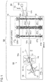
- Fig. 1 is a diagram for explaining a configuration (Example 1) of an atomic interferometer using a cold atomic beam generation apparatus
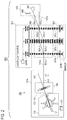
- Fig. 2 is a diagram for explaining a configuration (Example 2) of an atomic interferometer using a cold atomic beam generation apparatus.
- a cold atomic beam generation apparatus 100 according to the embodiment of the present invention and a Mach-Zehnder atomic interferometer 500 that utilizes the cold atomic beam generation apparatus 100 are described.
- the Mach-Zehnder atomic interferometer 500 includes: the cold atomic beam generation apparatus 100 that continuously generates a cold atomic beam 131a in which individual atoms are in the same state; an interference device 200; a moving standing light wave generator 300; and a monitor 400 (see Fig. 1 ).
- the cold atomic beam generation apparatus 100, the interference device 200, and the monitor 400 are housed inside a vacuum chamber not illustrated.
- the cold atomic beam generation apparatus 100 includes: inside a partition 100a of the vacuum chamber, an atomic source 110; a cold atomic beam generator 130 that uses pushing laser beam 121 to generate a cold atomic beam from atoms which have come from the atomic source 110 and have trapped in a space; and an atomic beam deflector 140 in which the cold atomic beam 131 from the cold atomic beam generator 130 goes.
- the cold atomic beam generation apparatus 100 has a configuration that includes the 2D + -MOT mechanism and the 2D-MOT mechanism, and thus consequently the cold atomic beam generator 130 corresponds to the 2D + -MOT mechanism and the atomic beam deflector 140 corresponds to the 2D-MOT mechanism.
- the 2D + -MOT mechanism includes: coils for forming a two-dimensional quadrupole magnetic field (for example, Ioffe coils); and three pairs of laser beams which are disposed on the three axes of symmetry of the two-dimensional quadrupole magnetic field.
- coils for forming a two-dimensional quadrupole magnetic field for example, Ioffe coils
- three pairs of laser beams which are disposed on the three axes of symmetry of the two-dimensional quadrupole magnetic field.
- the three pairs of laser beams apply a damping force to each atom according to the velocity of the atom (to form an optical molasses), and additionally the radiation pressure difference of each laser beam pair, which is caused by the Zeeman shift according to the position of the atom due to the two-dimensional quadrupole magnetic field and the transition selection rule in each laser beam pair, applies a damping force (for example, a force toward the zero magnetic field line of the two-dimensional quadrupole magnetic field) to each atom according to the position of the atom, resulting in generation of a cold atom cloud of atoms trapped in a space.
- a damping force for example, a force toward the zero magnetic field line of the two-dimensional quadrupole magnetic field
- Each of two out of the three laser beam pairs is a pair of circularly polarized light ⁇ + and ⁇ - (where ⁇ - corresponding to ⁇ + is formed by reflecting ⁇ + with a reflective quarter-wave plate) that travel in opposition to each other and also have the same frequency (specifically, a frequency slightly lower than the resonant frequency of the atom).
- the two laser beam pairs orthogonally intersect each other specifically, the traveling direction of ⁇ + for example in one of the laser beam pairs orthogonally intersects the traveling direction of ⁇ + for example in the other laser beam pair
- each of the two laser beam pairs intersects the zero magnetic field line of the two-dimensional quadrupole magnetic field formed by the coils.
- Each of the two laser beam pairs laser-cools atoms existing in the space inside the 2D + -MOT mechanism in a direction orthogonal to the zero magnetic field line.
- the remaining laser beam pair among the three laser beam pairs is a pair of circularly polarized light ⁇ + and ⁇ - that travel in opposition to each other on the zero magnetic field line of the two-dimensional quadrupole magnetic field and also have the same frequency (specifically, a frequency slightly lower than the resonant frequency of the atom).
- the laser beam pair laser-cools atoms existing in the space inside the 2D + -MOT mechanism in the direction of the zero magnetic field line. However, the beam intensity of one of the laser beams forming the laser beam pair is set stronger than the beam intensity of the other laser beam.
- the other laser beam is introduced into the space inside the coils using a perforated reflective plate disposed at a 45 degree angle with respect to the direction of the zero magnetic field line, and therefore the other laser light includes a "shadow (that is, dark part) in the direction of the zero magnetic field line" corresponding to the hole in the perforated reflective plate. Consequently, one of the laser beams effectively acts as the pushing laser beam 121 due to the beam intensity difference and the asymmetric scattering rates, and the cold atomic beam 131 is drawn out through the perforated reflective plate from the cold atom cloud trapped near the zero magnetic field line. Also, as described above, one of the laser beams (effectively the pushing laser beam) leaks out together with the cold atomic beam from the hole in the perforated reflective plate.
- the 2D-MOT mechanism has a configuration such that one laser beam pair on the zero magnetic field line of the two-dimensional quadrupole magnetic field is excluded from the 2D + -MOT mechanism.
- the traveling direction of the cold atomic beam 131 from the cold atomic beam generator 130 matches the traveling direction of the pushing laser beam 121 (in other words, one of the laser beams forming the one laser beam pair on the zero magnetic field line of the two-dimensional quadrupole magnetic field).
- the cold atomic beam generator 130 and the atomic beam deflector 140 have a positional relationship such that the zero magnetic field line of the quadrupole magnetic field in the 2D-MOT mechanism of the atomic beam deflector 140 intersects the traveling direction of the cold atomic beam 131 from the cold atomic beam generator 130 (in other words, the direction of the zero magnetic field line of the two-dimensional quadrupole magnetic field in the 2D + -MOT mechanism).
- the angle between the direction of the zero magnetic field line of the quadrupole magnetic field in the 2D-MOT mechanism and the direction of the zero magnetic field line of the two-dimensional quadrupole magnetic field in the 2D + -MOT mechanism is determined according to factors such as design conditions, but is set to a predetermined angle from 5 degrees or greater to 60 degrees or less, for example.
- the atomic source 110 has a configuration in which a solid is sublimated or a configuration in which a liquid evaporates or volatilizes.
- the solid or liquid is preferably made from a highly pure single element.
- gaseous atoms are obtained from the atomic source 110.
- a heating device is necessary, but in the case of using an element such as rubidium or cesium, the saturated vapor pressure is high (that is, the element readily vaporizes) at room temperature (that is, a temperature suited to human activity), and therefore sufficient gaseous atoms can be obtained without using a heating device.
- the gaseous atoms (hereinafter simply referred to as the atoms) filling the partition 100a of the vacuum chamber are naturally supplied to the 2D + -MOT mechanism (in this embodiment, the cold atomic beam generator 130).
- the pushing laser beam 121 is used to generate the cold atomic beam 131 from the cold atom cloud trapped in the space inside the coils, and furthermore, the pushing laser beam 121 leaks out in the traveling direction of the cold atomic beam 131.
- the total number of collisions per unit time and per unit volume between the cold atomic beam 131 and the atoms filling the partition 100a of the vacuum chamber is sufficiently small (in other words, the mean free path is long).
- the cold atomic beam 131 and the leaking pushing laser beam 121 enter the atomic beam deflector 140 having a configuration that includes the 2D-MOT mechanism. From the above-described positional relationship between the cold atomic beam generator 130 and the atomic beam deflector 140, the cold atomic beam 131 and the leaking pushing laser beam 121 obliquely cross the zero magnetic line of the quadrupole magnetic field in the 2D-MOT mechanism of the atomic beam deflector 140. Additionally, because of the damping force according to the velocity and position of each atom by the 2D-MOT mechanism, the path of the cold atomic beam 131 is changed to the direction of the zero magnetic field line of the quadrupole magnetic field in the 2D-MOT mechanism.
- the pushing laser beam 121 is unaffected by the 2D-MOT mechanism, and therefore the path of the pushing laser beam 121 is unchanged. Consequently, the atomic beam deflector 140 causes the cold atomic beam 131 to travel in a direction different from the traveling direction of the pushing laser beam 121.
- the individual atoms included in the cold atomic beam 131 from the atomic beam deflector 140 are set to the same energy level by optical pumping.
- the cold atomic beam 131a composed of atoms at the same energy level enter the interference device 200.
- the pushing laser beam 121 traveling in a direction different from the traveling direction of the cold atomic beam 131 (131a) is terminated appropriately and does not enter the interference device 200.
- the Mach-Zehnder atomic interferometer 500 uses nth-order Bragg diffraction (where n is a predetermined positive integer equal to or greater than 2).
- the moving standing light wave generator 300 generates three moving standing light waves (first moving standing light wave 201a, second moving standing light wave 201b, and third moving standing light wave 201c) that satisfy the nth-order Bragg condition.
- Condition are also met such that the first moving standing light wave 201a functions as a splitter of the atomic beam, the second moving standing light wave 201b functions as a mirror of the atomic beam, and the third moving standing light wave 201c functions as a combiner of the atomic beam.
- Each of the three moving standing light waves (first moving standing light wave 201a, second moving standing light wave 201b, third moving standing light wave 201c) meeting such conditions is achieved by appropriately setting the beam waist, wavelength, and light intensity of a Gaussian beam as well as setting the difference frequency between counterpropagating laser beams.
- the beam waist of the Gaussian beam can be optically set (for example, by condensing laser light with a lens), and the light intensity of the Gaussian beam can be electrically set (for example, by adjusting the output of the Gaussian beam).
- generation parameters of the moving standing light waves are different from generation parameters used in the related art, but since the configuration of the moving standing light wave generator 300 that generates the three moving standing light waves is not different from a configuration of a moving standing light wave generator in the related art, a description of the configuration of the moving standing light wave generator 300 is omitted (in Fig. 1 , components such as a laser light source, lenses, mirrors, and AOMs are illustrated as an outline).
- the cold atomic beam 131a passes through the three moving standing light waves 201a, 201b, and 201c.
- g, p 1 > in the same internal state is used.
- g, p 0 > changes to the superposition state of
- g, p 1 > immediately after passing through the first moving standing light wave 201a is 1:1.
- the cold atomic beam 131a splits into an atomic beam composed of atoms in the state
- g, p 1 > is a direction based on the nth-order Bragg condition.
- g, p 0 > that were not subjected to Bragg diffraction) and the direction based on the nth-order Bragg condition is n times the angle between the direction of the 0th order light and the direction based on the first-order Bragg condition. That is to say, the spread (in other words, deviation) between the traveling direction of the atomic beam composed of atoms in the state
- g, p 1 > pass through the second moving standing light wave 201b.
- g, p 0 > is reversed to an atomic beam composed of atoms in the state
- g, p 1 > is reversed to an atomic beam composed of atoms in the state
- g, p 1 > is deviated from the moving direction of atoms in the state
- g, p 1 > after passing through the second moving standing light wave 201b becomes parallel to the traveling direction of the atomic beam composed of atoms in the state
- each atom in transition from
- g, p 0 > is deviated from the moving direction of atoms in the state
- g, p 0 > after passing through the second moving standing light wave 201b becomes parallel to the traveling direction of the atomic beam composed of atoms in the state
- g, p 1 > pass through the third moving standing light wave 201c.
- g, p 1 > after the reversal cross each other.
- the traveling direction of the cold atomic beam 131b obtained after passing through the third moving standing light wave 201c is any one or both of the direction of the 0th order light and the direction based on the nth-order Bragg condition.
- the monitor 400 detects the angular velocity or the acceleration by monitoring the cold atomic beam 131b from the interference device 200 (in other words, the cold atomic beam 131b obtained after passing through the third moving standing light wave 201c).
- the monitor 400 irradiates the cold atomic beam 131b from the interference device 200 with probe light 408 and detects fluorescence from the atoms in the state
- the photodetector 409 include a photomultiplier tube and a fluorescence photodetector.
- a CCD image sensor can also be used as the photodetector 409.
- the atomic beam of one of the two paths after passing through the third moving standing light wave may be ionized by a laser beam or the like instead of the probe light, and the ions may be detected using the channeltron.
- the cold atomic beam generator 130 has a configuration that includes the 2D + -MOT mechanism.
- the cold atomic beam generator 130 is not limited to have a configuration that includes the 2D + -MOT mechanism and may also have a configuration that includes the LVIS mechanism, a configuration that includes the 2D-MOT mechanism, a configuration that includes the 2D-HP MOT mechanism, or a configuration that generates a cold atomic beam by using laser beams and a perforated pyramidal reflector, for example.
- the atomic beam deflector 140 has a configuration that includes the 2D-MOT configuration.
- the atomic beam deflector 140 is not limited to have a configuration that includes the 2D-MOT mechanism, and may also have a configuration that includes a moving molasses mechanism, for example (see Fig. 2 ).
- the moving molasses mechanism includes at least one pair of laser beams.
- the pair of laser beams forms a moving standing light wave.
- the moving standing light wave imparts a velocity to atoms in the drift direction.
- each pair forms a moving standing light wave. Atoms entering the intersection region between the two moving standing light waves are imparted with a velocity in the drift direction of the two moving standing light waves (specifically, the combined direction of the two drift directions).
- the cold atomic beam generator 130 and the atomic beam deflector 140 have a positional relationship such that the drift direction of the standing light waves in the moving molasses mechanism intersects (preferably orthogonally) the traveling direction of the cold atomic beam from the cold atomic beam generator.
- the cold atomic beam 131 and the leaking pushing laser beam 121 enter the atomic beam deflector 140 having a configuration that includes the moving molasses mechanism. From the above-described positional relationship between the cold atomic beam generator 130 and the atomic beam deflector 140, the cold atomic beam 131 and the leaking pushing laser beam 121 obliquely cross the drift direction of the standing light wave in the moving molasses mechanism of the atomic beam deflector 140. Thereafter, the path of the cold atomic beam 131 is changed by the principle of the moving molasses. However, the pushing laser beam 121 is unaffected by the moving molasses mechanism, and therefore the path of the pushing laser beam 121 is unchanged. Consequently, the atomic beam deflector 140 causes the cold atomic beam 131 to travel in a direction different from the traveling direction of the pushing laser beam 121.
- the foregoing embodiment describes a Mach-Zehnder atomic interferometer that uses the nth-order (n ⁇ 2) Bragg diffraction, but the atomic interferometer is not limited to this type and may also be a Mach-Zehnder atomic interferometer that uses two-photon Raman transitions caused by a moving standing light wave (see Reference Literature 1), for example.
- Reference Literature 1 T.L. Gustavson, P. Bouyer and M.A. Kasevich, "Precision Rotation Measurements with an Atom Interferometer Gyroscope," Phys. Rev. Lett. 78, 2046-2049, Published 17 March 1997 .
- the foregoing embodiment uses a Mach-Zehnder atomic interferometer that performs one split, one inversion, and one combination using three moving standing light waves, but the configuration thereof is not limited to such an embodiment, and the atomic interferometer of the present invention may also be carried out as an embodiment that uses a multi-stage Mach-Zehnder atomic interferometer that performs two or more splits, two or more inversions, and two or more combinations for example.
- a multi-stage Mach-Zehnder atomic interferometer see Reference Literature 2.
- Reference Literature 2 Takatoshi Aoki et al., "High-finesse atomic multiple-beam interferometer comprised of copropagating stimulated Raman-pulse fields," Phys. Rev. A, 63, 063611 (2001) - Published 16 May 2001 .
- the atomic interferometer of the present invention is not limited to a Mach-Zehnder atomic interferometer and may also be a Ramsey-Bordé atomic interferometer, for example.
Landscapes
- Physics & Mathematics (AREA)
- Spectroscopy & Molecular Physics (AREA)
- Engineering & Computer Science (AREA)
- General Engineering & Computer Science (AREA)
- High Energy & Nuclear Physics (AREA)
- General Physics & Mathematics (AREA)
- Plasma & Fusion (AREA)
- Optical Modulation, Optical Deflection, Nonlinear Optics, Optical Demodulation, Optical Logic Elements (AREA)
- Lasers (AREA)
- Instruments For Measurement Of Length By Optical Means (AREA)
Abstract
Description
- The present invention relates to a cold atomic beam generation technology and an atomic interferometer using the cold atomic beam generation technology.
- Recently, with the progression of laser technology, various cold atomic beam generation technologies have been developed. The technologies disclosed in Non-Patent Literatures 1 to 8 for example are known as cold atomic beam generation technologies.
- According to Non-Patent Literatures 1 to 3, atoms are cooled inside a two-dimensional magneto-optical trap (2D-MOT) mechanism that includes magnetic field generation coils called hairpin wires and pairs of laser beams for cooling, and the principle of moving-molasses is utilized to draw out a cold atomic beam from a cold atom cloud (for example, see
Fig. 1 of Non-Patent Literature 2). - According to Non-Patent Literature 4, atoms are cooled inside a 2D-MOT mechanism that includes magnetic field generation coils and pairs of laser beams for cooling, and a pushing laser beam is utilized to draw out a cold atomic beam from a cold atom cloud.
- According to Non-Patent Literature 5, in a configuration such that, in a three-dimensional magneto-optical trap (3D-MOT) mechanism, a retroreflector for generating one of three pairs of laser beams is replaced with a perforated reflective quarter-wave plate, asymmetric scattering rates in the one pair of laser beams are utilized to draw out a cold atomic beam from a cold atom cloud. This technology is referred to as a low-velocity intense source (LVIS).
- According to Non-Patent Literature 6, in a configuration such that one pair of laser beams in line with a zero magnetic field line of a two-dimensional quadrupole magnetic field is added to a 2D-MOT mechanism, differences in the beam intensity in the one pair of laser beams are utilized to draw out a cold atomic beam from a cold atom cloud (for example, see
Fig. 1 of Non-Patent Literature 6). This technology is referred to as 2D+-MOT. - According to Non-Patent Literature 7, laser beams and a perforated pyramidal reflector are used to cool atoms three-dimensionally and also draw out a cold atomic beam from a cold atom cloud.
- According to Non-Patent Literature 8, two types of laser beams (that is, a pushing laser beam and a hollow laser beam) that travel on the zero magnetic field line of a quadrupole magnetic field in a 2D-MOT mechanism are utilized to obtain a cold atomic beam with improved flux and velocity distribution (for example, see Fig. 3 of Non-Patent Literature 8). This technology is referred to as 2D-HP MOT.
-
- Non-Patent Literature 1: E. Riis, D.S. Weiss, K.A. Moler, and S. Chu, "Atom Funnel for the Production of a Slow, High-Density Atomic Beam," Phys. Rev. Lett. 64, 1658 (1990).
- Non-Patent Literature 2: Swanson, T.B.; Silva, N.J.; Mayer, Shannon K.; Maki, J.J.; and McIntyre, D.H., "Rubidium atomic funnel," (1996). Physics Faculty Publications and Presentations. 30.
- Non-Patent Literature 3: T.B. Swanson, N.J. Silva, S.K. Mayer, J.J. Maki and D.H. McIntyre: "Rubidium atomic funnel," J. Opt. Soc. Am. B, 13, 9, p. 1833 (1996).
- Non-Patent Literature 4: J. Schoser, A. Batar, R. Low, V. Schweikhard, A. Grabowski, Yu.B. Ovchinnikov, and T. Pfau, "Intense source of cold Rb atoms from a pure two-dimensional magneto-optical trap," PHYSICAL REVIEW A, 66, 023410 2002.
- Non-Patent Literature 5: Z. Lu, K. Corwin, M. Renn, M. Anderson, E. Cornell and C. Wieman: "Low-Velocity Intense Source of Atoms from a Magneto-optical Trap," Phys. Rev. Lett., 77, 16, pp. 3331-3334 (1996).
- Non-Patent Literature 6: K. Dieckmann, R. Spreeuw, M. Weidemuller and J. Walraven: "Two-dimensional magneto-optical trap as a source of slow atoms," Phys. Rev. A, 58, 5, pp. 3891-3895 (1998).
- Non-Patent Literature 7: J. Arlt, O. Marago, S. Webster, S. Hopkins and C. Foot: "A pyramidal magnetooptical trap as a source of slow atoms," Opt. Commun., December, pp. 303-309 (1998).
- Non-Patent Literature 8: Jia-Qiang Huang, Xue-Shu Yan, Chen-Fei Wu, Jian-Wei Zhang, and Li-Jun Wang, "Intense source of cold cesium atoms based on a two-dimensional magneto-optical trap with independent axial cooling and pushing," Chin. Phys. B Vol. 25, No. 6 063701 (2016).
- Cold atomic beam generation technology is used in various technologies, and is used in atomic interferometers such as a Mach-Zehnder atomic interferometer and a Ramsey-Bordé atomic interferometer, for example. In an atomic interferometer, a cold atomic beam is subjected to the action of moving standing light waves, each of which is generated by counterpropagating two laser beams having different frequencies and which has a drift velocity according to the difference frequency.
- According to cold atomic beam generation technology, the laser beam may travel in the traveling direction of the generated cold atomic beam in some cases. According to the configuration disclosed in Non-Patent Literature 4, because a cold atomic beam is drawn out from a cold atom cloud by using a pushing laser beam, the pushing laser beam travels in the traveling direction of the generated cold atomic beam. According to the configuration disclosed in Non-Patent Literature 5, one of the two laser beams forming the laser beam pair effectively acts as a pushing laser beam, and the pushing laser beam exits the hole in the perforated reflective quarter-wave plate together with the cold atomic beam. According to the configuration disclosed in Non-Patent Literature 6, one of the two laser beams forming the laser beam pair effectively acts as a pushing laser beam, and the pushing laser beam exits together with the cold atomic beam from the hole in the perforated reflective plate which is disposed to make one of the two laser beams oppose the other laser beam. According to the configuration disclosed in Non-Patent Literature 7, one of the laser beams acts as a pushing laser beam, and the laser beam exits together with the cold atomic beam from the hole in the perforated pyramidal reflector. According to the configuration disclosed in Non-Patent Literature 8, one of the two types of laser beams is a pushing laser beam, and the pushing laser beam exists together with the cold atomic beam from the hole in the perforated reflective plate for reflecting the other (that is, hollow laser beam) of the two types of laser beams.
- In such cases, because the pushing laser beam enters the atomic interferometer at the same time as the cold atomic beam, there is a possibility that the pushing laser beam will influence the atomic interference.
- However, these cold atomic beam generation technologies are capable of achieving cold atomic beams with low velocity, narrow velocity spread, and high flux, and it is desirable to be able to use these cold atomic beam generation technologies in atomic interferometers.
- Consequently, an object of the present invention is to provide a cold atomic beam generation technology that causes the cold atomic beam to travel in a direction different from the traveling direction of the pushing laser beam.
- A cold atomic beam generation technology of the present invention generates, by using a pushing laser beam, a cold atomic beam from atoms trapped in a space, and deflects the cold atomic beam by using a zero magnetic field line of a quadrupole magnetic field in a two-dimensional magneto-optical trap mechanism or by using a drift direction of a standing light wave in a moving molasses mechanism.
- An atomic interferometer of the present invention includes: a cold atomic beam generation apparatus to continuously generate a cold atomic beam; a moving standing light wave generator to generate three or more moving standing light waves; and an interference device to obtain an atomic beam as a result of interaction between the cold atomic beam and the three or more moving standing light waves. The cold atomic beam generation apparatus includes: an atomic source; a cold atomic beam generator to generate, by using a pushing laser beam, a cold atomic beam from atoms which have come from the atomic source and have trapped in a space; and an atomic beam deflector that the cold atomic beam from the cold atomic beam generator enters. The atomic beam deflector includes a two-dimensional magneto-optical trap mechanism or a moving molasses mechanism. A traveling direction of the cold atomic beam from the cold atomic beam generator matches a traveling direction of the pushing laser beam, and in a case where the atomic beam deflector includes the two-dimensional magneto-optical trap mechanism, a zero magnetic field line of a quadrupole magnetic field in the two-dimensional magneto-optical trap mechanism intersects the traveling direction of the cold atomic beam from the cold atomic beam generator, and in a case where the atomic beam deflector includes the moving molasses mechanism, a drift direction of a standing light wave in the moving molasses mechanism intersects the traveling direction of the cold atomic beam from the cold atomic beam generator.
- According to the present invention, an atomic beam deflector can be used to make the cold atomic beam travel in a direction different from the traveling direction of the pushing laser beam.
-
Fig. 1 is a diagram for explaining a configuration (Example 1) of an atomic interferometer using a cold atomic beam generation apparatus; and -
Fig. 2 is a diagram for explaining a configuration (Example 2) of an atomic interferometer using a cold atomic beam generation apparatus. - An embodiment of the present invention will be described with reference to the drawings. It should be noted that the drawings are provided to aid understanding of the embodiment, and the dimensions of the illustrated components are not accurate.
- In the exemplary embodiment, a cold atomic
beam generation apparatus 100 according to the embodiment of the present invention and a Mach-Zehnderatomic interferometer 500 that utilizes the cold atomicbeam generation apparatus 100 are described. The Mach-Zehnderatomic interferometer 500 includes: the cold atomicbeam generation apparatus 100 that continuously generates a coldatomic beam 131a in which individual atoms are in the same state; aninterference device 200; a moving standinglight wave generator 300; and a monitor 400 (seeFig. 1 ). In the embodiment, the cold atomicbeam generation apparatus 100, theinterference device 200, and themonitor 400 are housed inside a vacuum chamber not illustrated. - The cold atomic
beam generation apparatus 100 includes: inside apartition 100a of the vacuum chamber, anatomic source 110; a coldatomic beam generator 130 that uses pushinglaser beam 121 to generate a cold atomic beam from atoms which have come from theatomic source 110 and have trapped in a space; and anatomic beam deflector 140 in which the coldatomic beam 131 from the coldatomic beam generator 130 goes. In this embodiment, the cold atomicbeam generation apparatus 100 has a configuration that includes the 2D+-MOT mechanism and the 2D-MOT mechanism, and thus consequently the coldatomic beam generator 130 corresponds to the 2D+-MOT mechanism and theatomic beam deflector 140 corresponds to the 2D-MOT mechanism. - To give a simple example, the 2D+-MOT mechanism includes: coils for forming a two-dimensional quadrupole magnetic field (for example, Ioffe coils); and three pairs of laser beams which are disposed on the three axes of symmetry of the two-dimensional quadrupole magnetic field. In the 2D+-MOT mechanism, the three pairs of laser beams apply a damping force to each atom according to the velocity of the atom (to form an optical molasses), and additionally the radiation pressure difference of each laser beam pair, which is caused by the Zeeman shift according to the position of the atom due to the two-dimensional quadrupole magnetic field and the transition selection rule in each laser beam pair, applies a damping force (for example, a force toward the zero magnetic field line of the two-dimensional quadrupole magnetic field) to each atom according to the position of the atom, resulting in generation of a cold atom cloud of atoms trapped in a space.
- Each of two out of the three laser beam pairs is a pair of circularly polarized light σ+ and σ- (where σ- corresponding to σ+ is formed by reflecting σ+ with a reflective quarter-wave plate) that travel in opposition to each other and also have the same frequency (specifically, a frequency slightly lower than the resonant frequency of the atom). The two laser beam pairs orthogonally intersect each other (specifically, the traveling direction of σ+ for example in one of the laser beam pairs orthogonally intersects the traveling direction of σ+ for example in the other laser beam pair), and furthermore, each of the two laser beam pairs intersects the zero magnetic field line of the two-dimensional quadrupole magnetic field formed by the coils. Each of the two laser beam pairs laser-cools atoms existing in the space inside the 2D+-MOT mechanism in a direction orthogonal to the zero magnetic field line.
- The remaining laser beam pair among the three laser beam pairs is a pair of circularly polarized light σ+ and σ- that travel in opposition to each other on the zero magnetic field line of the two-dimensional quadrupole magnetic field and also have the same frequency (specifically, a frequency slightly lower than the resonant frequency of the atom). The laser beam pair laser-cools atoms existing in the space inside the 2D+-MOT mechanism in the direction of the zero magnetic field line. However, the beam intensity of one of the laser beams forming the laser beam pair is set stronger than the beam intensity of the other laser beam. Also, the other laser beam is introduced into the space inside the coils using a perforated reflective plate disposed at a 45 degree angle with respect to the direction of the zero magnetic field line, and therefore the other laser light includes a "shadow (that is, dark part) in the direction of the zero magnetic field line" corresponding to the hole in the perforated reflective plate. Consequently, one of the laser beams effectively acts as the pushing
laser beam 121 due to the beam intensity difference and the asymmetric scattering rates, and the coldatomic beam 131 is drawn out through the perforated reflective plate from the cold atom cloud trapped near the zero magnetic field line. Also, as described above, one of the laser beams (effectively the pushing laser beam) leaks out together with the cold atomic beam from the hole in the perforated reflective plate. - To give a simple example, the 2D-MOT mechanism has a configuration such that one laser beam pair on the zero magnetic field line of the two-dimensional quadrupole magnetic field is excluded from the 2D+-MOT mechanism.
- In such a cold atomic
beam generation apparatus 100, the traveling direction of the coldatomic beam 131 from the cold atomic beam generator 130 (that is, the direction of the zero magnetic field line of the two-dimensional quadrupole magnetic field) matches the traveling direction of the pushing laser beam 121 (in other words, one of the laser beams forming the one laser beam pair on the zero magnetic field line of the two-dimensional quadrupole magnetic field). - The cold
atomic beam generator 130 and theatomic beam deflector 140 have a positional relationship such that the zero magnetic field line of the quadrupole magnetic field in the 2D-MOT mechanism of theatomic beam deflector 140 intersects the traveling direction of the coldatomic beam 131 from the cold atomic beam generator 130 (in other words, the direction of the zero magnetic field line of the two-dimensional quadrupole magnetic field in the 2D+-MOT mechanism). The angle between the direction of the zero magnetic field line of the quadrupole magnetic field in the 2D-MOT mechanism and the direction of the zero magnetic field line of the two-dimensional quadrupole magnetic field in the 2D+-MOT mechanism is determined according to factors such as design conditions, but is set to a predetermined angle from 5 degrees or greater to 60 degrees or less, for example. - Also, the
atomic source 110 has a configuration in which a solid is sublimated or a configuration in which a liquid evaporates or volatilizes. The solid or liquid is preferably made from a highly pure single element. - In the cold atomic
beam generation apparatus 100 described above, first, gaseous atoms are obtained from theatomic source 110. In the case of using an element such as strontium or calcium, a heating device is necessary, but in the case of using an element such as rubidium or cesium, the saturated vapor pressure is high (that is, the element readily vaporizes) at room temperature (that is, a temperature suited to human activity), and therefore sufficient gaseous atoms can be obtained without using a heating device. - The gaseous atoms (hereinafter simply referred to as the atoms) filling the
partition 100a of the vacuum chamber are naturally supplied to the 2D+-MOT mechanism (in this embodiment, the cold atomic beam generator 130). In the 2D+-MOT mechanism, as described earlier, the pushinglaser beam 121 is used to generate the coldatomic beam 131 from the cold atom cloud trapped in the space inside the coils, and furthermore, the pushinglaser beam 121 leaks out in the traveling direction of the coldatomic beam 131. - In view of the flux of the cold
atomic beam 131 that can be achieved in light of the current technological level, the total number of collisions per unit time and per unit volume between the coldatomic beam 131 and the atoms filling thepartition 100a of the vacuum chamber is sufficiently small (in other words, the mean free path is long). - The cold
atomic beam 131 and the leaking pushinglaser beam 121 enter theatomic beam deflector 140 having a configuration that includes the 2D-MOT mechanism. From the above-described positional relationship between the coldatomic beam generator 130 and theatomic beam deflector 140, the coldatomic beam 131 and the leaking pushinglaser beam 121 obliquely cross the zero magnetic line of the quadrupole magnetic field in the 2D-MOT mechanism of theatomic beam deflector 140. Additionally, because of the damping force according to the velocity and position of each atom by the 2D-MOT mechanism, the path of the coldatomic beam 131 is changed to the direction of the zero magnetic field line of the quadrupole magnetic field in the 2D-MOT mechanism. However, the pushinglaser beam 121 is unaffected by the 2D-MOT mechanism, and therefore the path of the pushinglaser beam 121 is unchanged. Consequently, theatomic beam deflector 140 causes the coldatomic beam 131 to travel in a direction different from the traveling direction of the pushinglaser beam 121. The individual atoms included in the coldatomic beam 131 from theatomic beam deflector 140 are set to the same energy level by optical pumping. The coldatomic beam 131a composed of atoms at the same energy level enter theinterference device 200. The pushinglaser beam 121 traveling in a direction different from the traveling direction of the cold atomic beam 131 (131a) is terminated appropriately and does not enter theinterference device 200. - Before describing the
interference device 200, the moving standinglight wave generator 300 will be described. The Mach-Zehnderatomic interferometer 500 uses nth-order Bragg diffraction (where n is a predetermined positive integer equal to or greater than 2). The moving standinglight wave generator 300 generates three moving standing light waves (first moving standinglight wave 201a, second moving standinglight wave 201b, and third moving standinglight wave 201c) that satisfy the nth-order Bragg condition. Condition are also met such that the first moving standinglight wave 201a functions as a splitter of the atomic beam, the second moving standinglight wave 201b functions as a mirror of the atomic beam, and the third moving standinglight wave 201c functions as a combiner of the atomic beam. - Each of the three moving standing light waves (first moving standing
light wave 201a, second moving standinglight wave 201b, third moving standinglight wave 201c) meeting such conditions is achieved by appropriately setting the beam waist, wavelength, and light intensity of a Gaussian beam as well as setting the difference frequency between counterpropagating laser beams. Note that the beam waist of the Gaussian beam can be optically set (for example, by condensing laser light with a lens), and the light intensity of the Gaussian beam can be electrically set (for example, by adjusting the output of the Gaussian beam). In other words, generation parameters of the moving standing light waves are different from generation parameters used in the related art, but since the configuration of the moving standinglight wave generator 300 that generates the three moving standing light waves is not different from a configuration of a moving standing light wave generator in the related art, a description of the configuration of the moving standinglight wave generator 300 is omitted (inFig. 1 , components such as a laser light source, lenses, mirrors, and AOMs are illustrated as an outline). - In the
interference device 200, the coldatomic beam 131a passes through the three moving standinglight waves - In the course of the cold
atomic beam 131a passing through the first moving standinglight wave 201a, the state of the individual atoms in the initial state |g, p0> changes to the superposition state of |g, p0> and |g, p1>. By appropriately setting interaction between the first moving standinglight wave 201a and the atoms, in other words, by appropriately setting the beam waist, the wavelength, the light intensity and the difference frequency between the counterpropagating laser beams, the ratio between the existence probability of |g, p0> and the existence probability of |g, p1> immediately after passing through the first moving standinglight wave 201a is 1:1. While transiting from |g, p0> to |g, p1> through stimulated absorption and emission of 2n photons traveling against each other, each atom acquires momentum of 2n photons (=p1-p0). Consequently, the moving direction of atoms in the state |g, p1> is largely deviated from the moving direction of atoms in the state |g, p0>. In other words, in the course of the coldatomic beam 131a passing through the first moving standinglight wave 201a, the coldatomic beam 131a splits into an atomic beam composed of atoms in the state |g, p0> and an atomic beam composed of atoms in the state |g, p1> at a ratio of 1:1. The traveling direction of the atomic beam composed of atoms in the state |g, p1> is a direction based on the nth-order Bragg condition. The angle between the direction of 0th order light (that is, the traveling direction of the atomic beam composed of atoms in the state |g, p0> that were not subjected to Bragg diffraction) and the direction based on the nth-order Bragg condition is n times the angle between the direction of the 0th order light and the direction based on the first-order Bragg condition. That is to say, the spread (in other words, deviation) between the traveling direction of the atomic beam composed of atoms in the state |g, p0> and the traveling direction of the atomic beam composed of atoms in the state |g, p1> can be increased. - After the split, the atomic beam composed of atoms in the state |g, p0> and the atomic beam composed of atoms in the state |g, p1> pass through the second moving standing
light wave 201b. Here, by appropriately setting interaction between the second moving standinglight wave 201b and the atoms, in other words, by setting appropriately the beam waist, the wavelength, the light intensity and the difference frequency between the counterpropagating laser beams, the atomic beam composed of atoms in the state |g, p0> is reversed to an atomic beam composed of atoms in the state |g, p1> in the course of passing through the second moving standinglight wave 201b, and the atomic beam composed of atoms in the state |g, p1> is reversed to an atomic beam composed of atoms in the state |g, p0> in the course of passing through the second moving standinglight wave 201b. At this time, with regard to the former, the traveling direction of the atoms that have transitioned from |g, p0> to |g, p1> is deviated from the moving direction of atoms in the state |g, p0>, as described earlier. As a result, the traveling direction of the atomic beam composed of atoms in the state |g, p1> after passing through the second moving standinglight wave 201b becomes parallel to the traveling direction of the atomic beam composed of atoms in the state |g, p1> after passing through the first moving standinglight wave 201a. With regard to the latter, in transition from |g, p1> to |g, p0> through stimulated absorption and emission of 2n photons traveling against each other, each atom loses the same momentum as the momentum obtained from the 2n photons. In other words, the traveling direction of atoms after transition from |g, p1> to |g, p0> is deviated from the moving direction of atoms in the state |g, p1> before the transition. As a result, the traveling direction of the atomic beam composed of atoms in the state |g, p0> after passing through the second moving standinglight wave 201b becomes parallel to the traveling direction of the atomic beam composed of atoms in the state |g, p0> after passing through the first moving standinglight wave 201a. - After the reversal, the atomic beam composed of atoms in the state |g, p0> and the atomic beam composed of atoms in the state |g, p1> pass through the third moving standing
light wave 201c. In the course of the passing, the atomic beam composed of atoms in the state |g, p0> after the reversal and the inverted atomic beam composed of atoms in the state |g, p1> after the reversal cross each other. Here, by appropriately setting interaction between the third moving standinglight wave 201c and the atoms, in other words, by setting appropriately the beam waist, the wavelength, the light intensity and the difference frequency between the counterpropagating laser beams, it is possible to obtain anatomic beam 131b corresponding to a superposition state of |g, p0> and |g, p1> of individual atoms included in the crossing region between the atomic beam composed of atoms in the state |g, p0> and the atomic beam composed of atoms in the state |g, p1>. Theoretically, the traveling direction of the coldatomic beam 131b obtained after passing through the third moving standinglight wave 201c is any one or both of the direction of the 0th order light and the direction based on the nth-order Bragg condition. - While an angular velocity or an acceleration in a plane including two paths of the atomic beams from the action of the first moving standing
light wave 201a to the action of the third moving standinglight wave 201c is applied to the Mach-Zehnderatomic interferometer 500, a phase difference is produced in the two paths of the atomic beams from the action of the first moving standinglight wave 201a to the action of the third moving standinglight wave 201c, and this phase difference is reflected in the existence probabilities of the state |g, p0> and the state |g, p1> of the individual atoms after passing through the third moving standinglight wave 201c. Consequently, themonitor 400 detects the angular velocity or the acceleration by monitoring the coldatomic beam 131b from the interference device 200 (in other words, the coldatomic beam 131b obtained after passing through the third moving standinglight wave 201c). For example, themonitor 400 irradiates the coldatomic beam 131b from theinterference device 200 withprobe light 408 and detects fluorescence from the atoms in the state |g, p1> using aphotodetector 409. Examples of thephotodetector 409 include a photomultiplier tube and a fluorescence photodetector. According to the present embodiment, because spatial decomposition improves, namely because of the wide separation between the two paths (in other words, the atomic beam composed of atoms in the state |g, p0> and the atomic beam composed of atoms in the state |g, p1>) after passing through the third moving standing light wave, a CCD image sensor can also be used as thephotodetector 409. Alternatively, in the case of using a channeltron as thephotodetector 409, the atomic beam of one of the two paths after passing through the third moving standing light wave may be ionized by a laser beam or the like instead of the probe light, and the ions may be detected using the channeltron. - In the foregoing embodiment, the cold
atomic beam generator 130 has a configuration that includes the 2D+-MOT mechanism. However, because it is sufficient to generate a cold atomic beam from atoms trapped in a space by using a pushing laser beam, the coldatomic beam generator 130 is not limited to have a configuration that includes the 2D+-MOT mechanism and may also have a configuration that includes the LVIS mechanism, a configuration that includes the 2D-MOT mechanism, a configuration that includes the 2D-HP MOT mechanism, or a configuration that generates a cold atomic beam by using laser beams and a perforated pyramidal reflector, for example. - In the foregoing embodiment, the
atomic beam deflector 140 has a configuration that includes the 2D-MOT configuration. However, because it is sufficient to deflect the cold atomic beam from the coldatomic beam generator 130, theatomic beam deflector 140 is not limited to have a configuration that includes the 2D-MOT mechanism, and may also have a configuration that includes a moving molasses mechanism, for example (seeFig. 2 ). - To give a simple example, the moving molasses mechanism includes at least one pair of laser beams. The pair of laser beams forms a moving standing light wave. The moving standing light wave imparts a velocity to atoms in the drift direction. In the case where the moving molasses mechanism includes two pairs of laser beams, each pair forms a moving standing light wave. Atoms entering the intersection region between the two moving standing light waves are imparted with a velocity in the drift direction of the two moving standing light waves (specifically, the combined direction of the two drift directions).
- In the case where the
atomic beam deflector 140 has a configuration that includes the moving molasses mechanism, the coldatomic beam generator 130 and theatomic beam deflector 140 have a positional relationship such that the drift direction of the standing light waves in the moving molasses mechanism intersects (preferably orthogonally) the traveling direction of the cold atomic beam from the cold atomic beam generator. - The cold
atomic beam 131 and the leaking pushinglaser beam 121 enter theatomic beam deflector 140 having a configuration that includes the moving molasses mechanism. From the above-described positional relationship between the coldatomic beam generator 130 and theatomic beam deflector 140, the coldatomic beam 131 and the leaking pushinglaser beam 121 obliquely cross the drift direction of the standing light wave in the moving molasses mechanism of theatomic beam deflector 140. Thereafter, the path of the coldatomic beam 131 is changed by the principle of the moving molasses. However, the pushinglaser beam 121 is unaffected by the moving molasses mechanism, and therefore the path of the pushinglaser beam 121 is unchanged. Consequently, theatomic beam deflector 140 causes the coldatomic beam 131 to travel in a direction different from the traveling direction of the pushinglaser beam 121. - The foregoing embodiment describes a Mach-Zehnder atomic interferometer that uses the nth-order (n ≥ 2) Bragg diffraction, but the atomic interferometer is not limited to this type and may also be a Mach-Zehnder atomic interferometer that uses two-photon Raman transitions caused by a moving standing light wave (see Reference Literature 1), for example. Reference Literature 1: T.L. Gustavson, P. Bouyer and M.A. Kasevich, "Precision Rotation Measurements with an Atom Interferometer Gyroscope," Phys. Rev. Lett. 78, 2046-2049, Published 17 March 1997.
- As another example, the foregoing embodiment uses a Mach-Zehnder atomic interferometer that performs one split, one inversion, and one combination using three moving standing light waves, but the configuration thereof is not limited to such an embodiment, and the atomic interferometer of the present invention may also be carried out as an embodiment that uses a multi-stage Mach-Zehnder atomic interferometer that performs two or more splits, two or more inversions, and two or more combinations for example. For an example of such a multi-stage Mach-Zehnder atomic interferometer, see Reference Literature 2. Reference Literature 2: Takatoshi Aoki et al., "High-finesse atomic multiple-beam interferometer comprised of copropagating stimulated Raman-pulse fields," Phys. Rev. A, 63, 063611 (2001) - Published 16 May 2001.
- Also, the atomic interferometer of the present invention is not limited to a Mach-Zehnder atomic interferometer and may also be a Ramsey-Bordé atomic interferometer, for example.
- The foregoing describes embodiments of the present invention, but the present invention is not limited to these embodiments. Various modification and alterations are possible without departing from the gist of the present invention. The embodiments have been selected and describe to explain the principle and a practical application of the present invention. The present invention is used as various embodiments in association with various modifications or alterations, and the various modifications or alterations are determined according to the anticipated usage. All such modifications and alterations are intended to be included within the scope of the present invention as defined by the appended claims and are intended to be given the same protection when interpreted according to their fair, lawful, and impartial scope.
-
- 100
- cold atomic beam generation apparatus
- 100a
- partition
- 110
- atomic source
- 121
- pushing laser beam
- 130
- cold atomic beam generator
- 140
- atomic beam deflector
- 131
- cold atomic beam
- 131a
- cold atomic beam
- 131b
- cold atomic beam
- 200
- interference device
- 201a
- first moving standing light wave
- 201b
- second moving standing light wave
- 201c
- third moving standing light wave
- 300
- moving standing light wave generator
- 400
- monitor
- 408
- probe light
- 409
- photodetector
- 500
- atomic interferometer
Claims (5)
- A method for generating a cold atomic beam, the method comprising:a cold atomic beam generating step of generating the cold atomic beam from atoms trapped in a space, by using a pushing laser beam; andan atomic beam deflecting step of deflecting the cold atomic beam, whereinin the atomic beam deflecting step, the cold atomic beam is deflected by using a zero magnetic field line of a quadrupole magnetic field in a two-dimensional magneto-optical trap mechanism or by using a drift direction of a standing light wave in a moving molasses mechanism.
- An apparatus for generating a cold atomic beam, the apparatus comprising:an atomic source;a cold atomic beam generator to generate the cold atomic beam from atoms come from the atomic source and trapped in a space, by using a pushing laser beam; andan atomic beam deflector that the cold atomic beam from the cold atomic beam generator enters, whereinthe atomic beam deflector includes a two-dimensional magneto-optical trap mechanism or a moving molasses mechanism,a traveling direction of the cold atomic beam from the cold atomic beam generator matches a traveling direction of the pushing laser beam,in a case where the atomic beam deflector includes the two-dimensional magneto-optical trap mechanism, a zero magnetic field line of a quadrupole magnetic field in the two-dimensional magneto-optical trap mechanism intersects the traveling direction of the cold atomic beam from the cold atomic beam generator, andin a case where the atomic beam deflector includes the moving molasses mechanism, a drift direction of a standing light wave in the moving molasses mechanism intersects the traveling direction of the cold atomic beam from the cold atomic beam generator.
- The apparatus according to Claim 2, wherein
the atomic source has a configuration in which a solid is sublimated or a configuration in which a liquid evaporates or volatilizes. - An atomic interferometer comprising:a cold atomic beam generation apparatus to continuously generate a cold atomic beam;a moving standing light wave generator to generate three or more moving standing light waves; andan interference device to obtain an atomic beam as a result of interaction between the cold atomic beam and the three or more moving standing light waves, whereinthe cold atomic beam generation apparatus includesan atomic source,a cold atomic beam generator to generate a cold atomic beam from atoms come from the atomic source and trapped in a space, by using a pushing laser beam, andan atomic beam deflector that the cold atomic beam from the cold atomic beam generator enters,the atomic beam deflector includes a two-dimensional magneto-optical trap mechanism or a moving molasses mechanism,a traveling direction of the cold atomic beam from the cold atomic beam generator matches a traveling direction of the pushing laser beam,in a case where the atomic beam deflector includes the two-dimensional magneto-optical trap mechanism, a zero magnetic field line of a quadrupole magnetic field in the two-dimensional magneto-optical trap mechanism intersects the traveling direction of the cold atomic beam from the cold atomic beam generator, andin a case where the atomic beam deflector includes the moving molasses mechanism, a drift direction of a standing light wave in the moving molasses mechanism intersects the traveling direction of the cold atomic beam from the cold atomic beam generator.
- The atomic interferometer according to Claim 4, wherein
each of the moving standing light waves satisfies an nth-order Bragg condition, where n is a positive integer equal to or greater than 2.
Applications Claiming Priority (2)
| Application Number | Priority Date | Filing Date | Title |
|---|---|---|---|
| JP2018143782A JP6650647B2 (en) | 2018-07-31 | 2018-07-31 | Cooled atom beam generation method, cooled atom beam generator, atomic interferometer |
| PCT/JP2019/022443 WO2020026588A1 (en) | 2018-07-31 | 2019-06-06 | Cold atom beam generation method, cold atom beam generation device, and atomic interferometer |
Publications (2)
| Publication Number | Publication Date |
|---|---|
| EP3799077A1 true EP3799077A1 (en) | 2021-03-31 |
| EP3799077A4 EP3799077A4 (en) | 2021-08-25 |
Family
ID=69232392
Family Applications (1)
| Application Number | Title | Priority Date | Filing Date |
|---|---|---|---|
| EP19844021.6A Withdrawn EP3799077A4 (en) | 2018-07-31 | 2019-06-06 | COLD ATOM BEAM GENERATION PROCESS, COLD ATOM BEAM GENERATION DEVICE AND ATOMIC INTERFEROMETER |
Country Status (6)
| Country | Link |
|---|---|
| US (1) | US20210233676A1 (en) |
| EP (1) | EP3799077A4 (en) |
| JP (1) | JP6650647B2 (en) |
| CN (1) | CN112236833A (en) |
| AU (1) | AU2019316312A1 (en) |
| WO (1) | WO2020026588A1 (en) |
Families Citing this family (9)
| Publication number | Priority date | Publication date | Assignee | Title |
|---|---|---|---|---|
| JP6713643B2 (en) * | 2018-12-07 | 2020-06-24 | 日本航空電子工業株式会社 | Atomic beam collimation method, atomic beam collimator, atomic interferometer, atomic gyroscope |
| CN111584115B (en) * | 2020-04-26 | 2022-02-11 | 中国科学院西安光学精密机械研究所 | Three-dimensional magneto-optical trap device for laser-cooled atoms with dual beam input |
| JP6948656B1 (en) | 2020-10-08 | 2021-10-13 | 日本航空電子工業株式会社 | Inertia sensor, atom interferometer, method of adjusting atomic speed, device for adjusting atomic speed |
| JP6948655B1 (en) * | 2020-10-08 | 2021-10-13 | 日本航空電子工業株式会社 | Inertia sensor, atom interferometer, method of adjusting the speed and course of atomic rays, device for adjusting the speed and course of atomic rays |
| WO2023243246A1 (en) * | 2022-06-14 | 2023-12-21 | 国立研究開発法人理化学研究所 | Magnetic optical trap device, physical package, physical package for optical lattice watch, physical package for atomic watch, physical package for atomic interferometer, physical package for quantom information processing device, and physical package system |
| US12444517B2 (en) * | 2022-09-15 | 2025-10-14 | Northrop Grumman Systems Corporation | Magneto-optical trap system |
| CN115767870B (en) * | 2022-11-04 | 2025-08-19 | 清华大学 | Preparation device for three-dimensional cooling continuous atomic beam |
| JP2025014818A (en) | 2023-07-19 | 2025-01-30 | 日本航空電子工業株式会社 | Quantum collimation method for atomic beam, quantum collimator for atomic beam, atom interferometer, and atomic gyroscope |
| JP2025022116A (en) | 2023-08-02 | 2025-02-14 | 国立大学法人東京科学大学 | Inertial Sensors |
Family Cites Families (16)
| Publication number | Priority date | Publication date | Assignee | Title |
|---|---|---|---|---|
| US4992656A (en) * | 1987-10-26 | 1991-02-12 | Clauser John F | Rotation, acceleration, and gravity sensors using quantum-mechanical matter-wave interferometry with neutral atoms and molecules |
| JPH06112551A (en) * | 1992-09-25 | 1994-04-22 | Nippon Telegr & Teleph Corp <Ntt> | Slow atom beam generation method and its equipment |
| JP2830849B2 (en) * | 1996-07-19 | 1998-12-02 | 日本電気株式会社 | Atomic beam pattern forming method using atomic beam holography |
| US6303928B1 (en) * | 1998-12-21 | 2001-10-16 | The Aerospace Corporation | Continuous cold atom beam atomic system |
| FR2799014B1 (en) * | 1999-09-27 | 2001-12-07 | Univ Paris 13 | PROCESS AND INSTALLATION OF ATOMIC INTERFEROMETRY NANOLITHOGRAPHY |
| JP3972972B2 (en) * | 2000-06-02 | 2007-09-05 | 独立行政法人科学技術振興機構 | Atomic beam generation method and apparatus |
| CN1145792C (en) * | 2001-06-01 | 2004-04-14 | 中国科学院上海光学精密机械研究所 | atomic beam interferometer |
| JP3918055B2 (en) * | 2003-02-13 | 2007-05-23 | 独立行政法人情報通信研究機構 | An atomic lithography apparatus using an electro-optic effect and a method for manufacturing an atomic structure. |
| CN1333622C (en) * | 2004-12-02 | 2007-08-22 | 清华大学 | A method and device for generating a cold atomic beam |
| GB0519251D0 (en) * | 2005-09-21 | 2005-10-26 | Univ Hertfordshire | Apparatus and methods for magneto and optical manipulation of atomic beams |
| EP2131500A3 (en) * | 2008-06-02 | 2012-03-07 | SEPA - Sistemi Elettronici Per Automazione S.P.A. | Atomic beam tube with counter propagating optical or atomic beams |
| US9470707B2 (en) * | 2012-02-17 | 2016-10-18 | Honeywell International Inc. | Atom interferometer with adaptive launch direction and/or position |
| US9568316B2 (en) * | 2013-03-15 | 2017-02-14 | The Charles Stark Draper Laboratory, Inc. | Ring architecture for sequential operation of an atomic gyroscope |
| GB201410298D0 (en) * | 2014-06-10 | 2014-07-23 | Sec Dep For Business Innovation & Skills The | Waveguide diffraction beam splitters for matter waves based on crossed interfering laser beams |
| JP2017125689A (en) * | 2016-01-12 | 2017-07-20 | セイコーエプソン株式会社 | Magnetic measuring device, gas cell, manufacturing method of magnetic measuring device, and manufacturing method of gas cell |
| US10157692B2 (en) * | 2016-06-22 | 2018-12-18 | The Charles Stark Draper Laboratory, Inc. | Cold atom interferometry |
-
2018
- 2018-07-31 JP JP2018143782A patent/JP6650647B2/en not_active Expired - Fee Related
-
2019
- 2019-06-06 US US16/972,248 patent/US20210233676A1/en not_active Abandoned
- 2019-06-06 EP EP19844021.6A patent/EP3799077A4/en not_active Withdrawn
- 2019-06-06 CN CN201980037765.3A patent/CN112236833A/en active Pending
- 2019-06-06 AU AU2019316312A patent/AU2019316312A1/en not_active Abandoned
- 2019-06-06 WO PCT/JP2019/022443 patent/WO2020026588A1/en not_active Ceased
Also Published As
| Publication number | Publication date |
|---|---|
| WO2020026588A1 (en) | 2020-02-06 |
| AU2019316312A1 (en) | 2021-01-14 |
| EP3799077A4 (en) | 2021-08-25 |
| US20210233676A1 (en) | 2021-07-29 |
| JP2020020636A (en) | 2020-02-06 |
| JP6650647B2 (en) | 2020-02-19 |
| CN112236833A (en) | 2021-01-15 |
Similar Documents
| Publication | Publication Date | Title |
|---|---|---|
| US20210233676A1 (en) | Method for generating cold atomic beam, apparatus for generating cold atomic beam, and atomic interferometer | |
| Camposeo et al. | A cold cesium atomic beam produced out of a pyramidal funnel | |
| US20250189313A1 (en) | Method for adjusting speed and course of atomic beam | |
| CN112955978B (en) | Atomic beam collimation method, atomic beam collimator, atomic interferometer, atomic gyroscope | |
| CN116420080B (en) | Inertial sensors, atomic interferometers, methods for adjusting atomic velocity, devices for adjusting atomic velocity | |
| CN1333622C (en) | A method and device for generating a cold atomic beam | |
| US20200333139A1 (en) | Mach-zehnder type atomic interferometric gyroscope | |
| US20200318968A1 (en) | Mach-zehnder type atomic interferometric gyroscope | |
| JP2025014818A (en) | Quantum collimation method for atomic beam, quantum collimator for atomic beam, atom interferometer, and atomic gyroscope | |
| Kim et al. | Cold atomic beam produced by a conical mirror funnel | |
| Ding | Narrow line cooling of 84Sr | |
| CN116324426B (en) | Inertial sensor, atomic interferometer, method for adjusting speed and travel path of atomic beam, and device for adjusting speed and travel path of atomic beam | |
| Robert | Toward an experiment of matter-wave interferometry based on strontium | |
| JP7201172B2 (en) | Atomic interferometer diffraction image detection method, atomic interferometer, atomic gyroscope | |
| Moriya | Collective effects in light scattering from cold strontium clouds | |
| Lu | Excitation of helium to Rydberg states using STIRAP | |
| Geldhof | Development of a saturated absorption spectroscopy setup at igisol | |
| Chikkatur | Construction and characterization of a Magneto-Optical Trap (MOT) | |
| Krokhin | The first laser was created 50 years ago | |
| Colla | Experiments with a Metastable Helium Atomic | |
| Middelmann et al. | Long range transport of ultra cold atoms in a far-detuned 1D optical lattice |
Legal Events
| Date | Code | Title | Description |
|---|---|---|---|
| STAA | Information on the status of an ep patent application or granted ep patent |
Free format text: STATUS: THE INTERNATIONAL PUBLICATION HAS BEEN MADE |
|
| PUAI | Public reference made under article 153(3) epc to a published international application that has entered the european phase |
Free format text: ORIGINAL CODE: 0009012 |
|
| STAA | Information on the status of an ep patent application or granted ep patent |
Free format text: STATUS: REQUEST FOR EXAMINATION WAS MADE |
|
| 17P | Request for examination filed |
Effective date: 20201221 |
|
| AK | Designated contracting states |
Kind code of ref document: A1 Designated state(s): AL AT BE BG CH CY CZ DE DK EE ES FI FR GB GR HR HU IE IS IT LI LT LU LV MC MK MT NL NO PL PT RO RS SE SI SK SM TR |
|
| AX | Request for extension of the european patent |
Extension state: BA ME |
|
| A4 | Supplementary search report drawn up and despatched |
Effective date: 20210722 |
|
| RIC1 | Information provided on ipc code assigned before grant |
Ipc: G21K 1/00 20060101AFI20210716BHEP Ipc: G01B 9/02 20060101ALI20210716BHEP Ipc: H01S 1/06 20060101ALI20210716BHEP Ipc: H05H 3/02 20060101ALI20210716BHEP |
|
| DAV | Request for validation of the european patent (deleted) | ||
| DAX | Request for extension of the european patent (deleted) | ||
| STAA | Information on the status of an ep patent application or granted ep patent |
Free format text: STATUS: THE APPLICATION IS DEEMED TO BE WITHDRAWN |
|
| 18D | Application deemed to be withdrawn |
Effective date: 20220222 |