EP3798733A1 - Image forming apparatus - Google Patents
Image forming apparatus Download PDFInfo
- Publication number
- EP3798733A1 EP3798733A1 EP20194290.1A EP20194290A EP3798733A1 EP 3798733 A1 EP3798733 A1 EP 3798733A1 EP 20194290 A EP20194290 A EP 20194290A EP 3798733 A1 EP3798733 A1 EP 3798733A1
- Authority
- EP
- European Patent Office
- Prior art keywords
- developer
- controller
- image forming
- toner
- thinning rate
- Prior art date
- Legal status (The legal status is an assumption and is not a legal conclusion. Google has not performed a legal analysis and makes no representation as to the accuracy of the status listed.)
- Withdrawn
Links
Images


Classifications
-
- G—PHYSICS
- G03—PHOTOGRAPHY; CINEMATOGRAPHY; ANALOGOUS TECHNIQUES USING WAVES OTHER THAN OPTICAL WAVES; ELECTROGRAPHY; HOLOGRAPHY
- G03G—ELECTROGRAPHY; ELECTROPHOTOGRAPHY; MAGNETOGRAPHY
- G03G15/00—Apparatus for electrographic processes using a charge pattern
- G03G15/06—Apparatus for electrographic processes using a charge pattern for developing
- G03G15/08—Apparatus for electrographic processes using a charge pattern for developing using a solid developer, e.g. powder developer
- G03G15/0806—Apparatus for electrographic processes using a charge pattern for developing using a solid developer, e.g. powder developer on a donor element, e.g. belt, roller
-
- G—PHYSICS
- G03—PHOTOGRAPHY; CINEMATOGRAPHY; ANALOGOUS TECHNIQUES USING WAVES OTHER THAN OPTICAL WAVES; ELECTROGRAPHY; HOLOGRAPHY
- G03G—ELECTROGRAPHY; ELECTROPHOTOGRAPHY; MAGNETOGRAPHY
- G03G15/00—Apparatus for electrographic processes using a charge pattern
- G03G15/04—Apparatus for electrographic processes using a charge pattern for exposing, i.e. imagewise exposure by optically projecting the original image on a photoconductive recording material
- G03G15/04018—Image composition, e.g. adding or superposing informations on the original image
-
- G—PHYSICS
- G03—PHOTOGRAPHY; CINEMATOGRAPHY; ANALOGOUS TECHNIQUES USING WAVES OTHER THAN OPTICAL WAVES; ELECTROGRAPHY; HOLOGRAPHY
- G03G—ELECTROGRAPHY; ELECTROPHOTOGRAPHY; MAGNETOGRAPHY
- G03G15/00—Apparatus for electrographic processes using a charge pattern
- G03G15/50—Machine control of apparatus for electrographic processes using a charge pattern, e.g. regulating differents parts of the machine, multimode copiers, microprocessor control
- G03G15/5025—Machine control of apparatus for electrographic processes using a charge pattern, e.g. regulating differents parts of the machine, multimode copiers, microprocessor control by measuring the original characteristics, e.g. contrast, density
-
- G—PHYSICS
- G03—PHOTOGRAPHY; CINEMATOGRAPHY; ANALOGOUS TECHNIQUES USING WAVES OTHER THAN OPTICAL WAVES; ELECTROGRAPHY; HOLOGRAPHY
- G03G—ELECTROGRAPHY; ELECTROPHOTOGRAPHY; MAGNETOGRAPHY
- G03G15/00—Apparatus for electrographic processes using a charge pattern
- G03G15/55—Self-diagnostics; Malfunction or lifetime display
- G03G15/553—Monitoring or warning means for exhaustion or lifetime end of consumables, e.g. indication of insufficient copy sheet quantity for a job
- G03G15/556—Monitoring or warning means for exhaustion or lifetime end of consumables, e.g. indication of insufficient copy sheet quantity for a job for toner consumption, e.g. pixel counting, toner coverage detection or toner density measurement
Definitions
- Embodiments of the present disclosure generally relate to an image forming apparatus.
- JP-2018-010230-A discloses the image forming apparatus that adjusts a pixel thinning rate based on a fixing pressure and paper information.
- JP-2018-010230-A does not mind how to improve a yield that is the number of sheets having images that one toner cartridge can print.
- An object of the present disclosure is to provide an image forming apparatus that can control image densities to be suitable and increase a yield.
- an image forming apparatus according to claim 1 Advantageous embodiments are defined by the dependent claims.
- the image forming apparatus includes a developer bearer configured to bear developer, a container configured to contain the developer, a developer supplier configured to supply the developer supplied from the container to the developer bearer, and a controller.
- the controller is configured to perform a pixel thinning rate control that thins out a pixel based on an amount of the developer conveyed on the developer bearer.
- the image forming apparatus can control the image densities to be suitable and increase the yield.
- the image forming apparatus according to the present embodiment forms images by an electrophotographic method and has the following features in an image density control to reduce toner consumption.
- the image forming apparatus according to the present embodiment uses a characteristic that the increase in the number of printed sheets darkens the image and increases a pixel thinning rate with the increase in the number of printed sheets to maintain a constant image density and save toner consumption.
- FIG. 1 is a schematic cross-sectional view illustrating a configuration of an image forming apparatus 1000 including a developer replenishment control system.
- the image forming apparatus 1000 is a monochrome image forming apparatus including an apparatus body 100 in which a process unit 1 as an image forming unit is removably installed.
- the process unit 1 includes a photoconductor 2 as an image bearer to bear images on a surface of the photoconductor 2, a charging roller 3 as a charger to charge the surface of the photoconductor 2, a developing device 4 to develop a latent image on the photoconductor 2 into a visible image, and a cleaning blade 5 as a cleaner to clean the surface of the photoconductor 2.
- the process unit 1 includes a toner cartridge 7 as a storage unit that stores toner as a developer. The toner cartridge 7 is detachably attached to the process unit 1.
- the toner cartridge 7 includes a toner container 8 to store toner supplied to an image forming portion of the developing device 4 and a toner collection container 9 to collect waste toner removed by the cleaning blade 5.
- the toner container 8 and the toner collection container 9 integrally form a container body 22.
- the developing device 4 in the present embodiment uses one-component developer including toner particles and not including carrier. Additionally, for example, toner used in the present embodiment is polyester toner including polyester resin mother particles.
- the image forming apparatus 1000 further includes a light-emitting diode (LED) head array 6 as an exposure device to expose the surface of the photoconductor 2, disposed facing the photoconductor 2.
- the image forming apparatus 1000 includes a transfer device 10, a sheet feeder 11, a fixing device 12, and an output device 13.
- the transfer device 10 transfers an image onto a sheet P as a recording medium.
- the sheet feeder 11 feeds or supplies the sheet P.
- the fixing device 12 fixes the transferred image onto the sheet P.
- the output device 13 ejects the sheet P outside the apparatus body 100.
- the sheets P may be thick paper, post cards, envelopes, plain paper, thin paper, coated paper, art paper, tracing paper, or the like.
- the sheets P as recording media may be overhead projector (OHP) transparencies (OHP sheets).
- the transfer device 10 includes a transfer roller 14 as a transfer member.
- the transfer roller 14 is in contact with the photoconductor 2 when the process unit 1 is installed in the apparatus body 100 of the image forming apparatus 1000.
- a transfer nip region is formed at a contact part at which the photoconductor 2 and the transfer roller 14 contact to each other.
- the transfer roller 14 is applied with at least one of a predetermined direct current (DC) voltage and a predetermined alternating current (AC) voltage.
- the sheet feeder 11 includes a sheet tray 15 that loads a plurality of sheets P and a feed roller 16 that feeds an uppermost sheet P of the plurality of sheets P loaded on the sheet tray 15 toward a registration roller pair 17.
- the registration roller pair 17 is disposed downstream from the feed roller 16 in a conveyance direction of the sheet P.
- the registration roller pair 17 functions as a timing roller pair to convey the sheet P to a transfer nip region at a proper timing of conveyance of the sheet P.
- the fixing device 12 includes a fixing roller 18 as a fixing member and a pressure roller 19 as a pressure member.
- a heater heats the fixing roller 18.
- the pressure roller 19 is pressed against and contacts the fixing roller 18 to form a fixing nip in the area of contact between the pressure roller 19 and the fixing roller 18.
- the output device 13 includes an output roller pair 20.
- the output roller pair 20 ejects the sheet P outside the apparatus body 100.
- the ejected sheet P is stacked on an output tray 21 that is a partly recessed upper face of the apparatus body 100.
- the developer replenishment control system may be configured by the toner cartridge 7, the developing device 4, a remaining amount detector that detects a remaining amount of the developer remaining in the image forming portion of the developing device 4, and a controller 900 that controls an amount of the developer supplied from the storage unit to the image forming portion of the developing device 4.
- FIG. 2 is a schematic explanatory view illustrating attachment/detachment of a process unit 1 to/from the apparatus body 100 of the image forming apparatus 1000.
- an openable and closable cover 101 is provided on a rear side of the apparatus body 100. Opening the cover 101 causes a link mechanism to retract the light-emitting diode head array 6 upward.
- the above-described configuration enables an operator to open the cover 101 and remove the process unit 1 from the rear side (or right or left side) of the apparatus body 100 avoiding the interference between the light-emitting diode head array 6 and the process unit 1.
- the process unit 1 attached the toner cartridge 7, as one unit, can be installed in or removed from the rear side (or the right or left side) of the apparatus body 100.
- the toner cartridge 7 is attachable to and detachable from the process unit 1 both when the process unit 1 is installed in the apparatus body 100 and when the process unit 1 is removed from the apparatus body 100.
- FIG. 3 is a schematic cross-sectional view illustrating a configuration of the developing device 4 provided in the process unit 1 of the image forming apparatus 1000.
- the developing device 4 provided in the process unit 1 includes a development housing 30 that accommodates toner, and a developing roller 31 as a developer bearer to bear toner.
- the development housing 30 can be regarded as an image forming portion of the developing device 4.
- the developing device 4 includes a supply roller 32 as a developer supplier to supply toner to the developing roller 31, a doctor blade 33 as a regulator to regulate an amount of toner borne on the developing roller 31, a first developer conveyor 34, and a second developer conveyor 35.
- the first developer conveyor 34 and the second developer conveyor 35 convey the toner.
- the developing roller 31 rotates counterclockwise in FIG. 3 as indicated an arrow illustrated in FIG. 3 and transports developer carried thereon to a position facing the doctor blade 33 and a position facing the photoconductor 2.
- the supply roller 32 abuts against the developing roller 31 and supplies toner in the development housing 30 to a surface layer of the developing roller 31 by rotating counterclockwise in FIG. 3 , that is, in a direction counter to the direction of rotation of the developing roller 31.
- the ratio of rotational frequency of the supply roller 32 to that of the developing roller 31 is 1 so that toner can be supplied reliably.
- One end of the doctor blade 33 is in contact with a surface of the developing roller 31, forming a regulation nip therebetween. While toner supplied to the developing roller 31 by the supply roller 32 passes through the regulation nip between the developing roller 31 and the doctor blade 33, the amount of toner is adjusted. Simultaneously, toner is charged by friction.
- a toner cartridge 7 contains fresh toner to be supplied and is detachably attached to an upper portion of the development housing 30. Therefore, the upper portion of the development housing 30 has a supply port 30a to supply the toner in the toner cartridge 7 into the development housing 30.
- the toner is supplied to the development housing 30 according to detection results by a remaining amount detecting sensor as the remaining amount detector configured to detect an amount of toner remaining in the development housing 30. That is, when the remaining amount detecting sensor detects that the toner has been consumed in the development housing 30 and the toner amount has become equal to or less than a predetermined value, the toner cartridge 7 is driven for a predetermined time. As a result, a predetermined amount of toner is supplied to the development housing 30.
- the controller 900 as a control device provided in the image forming apparatus 1000 adjusts a driving amount of a driving mechanism based on a remaining amount lower limit value, a remaining amount upper limit value, which are predetermined, and the remaining amount of toner detected by the remaining amount detecting sensor and drives the drive mechanism.
- the controller 900 controls the amount of toner supplied from the toner cartridge 7 as the storage unit to the image forming portion of the developing device 4 (the development housing 30).
- a partition 36 substantially parallel to an axis direction of the developing roller 31 is disposed inside the development housing 30.
- the partition 36 divides, but not completely, the development housing 30 into a first compartment A including the supply port 30a and a second compartment B including the developing roller 31, the doctor blade 33, and the like.
- the partition 36 extends in the vertical direction.
- the first compartment A and the second compartment B are arranged horizontally adjacent to each other.
- the first developer conveyor 34 is disposed in the first compartment A, and the second developer conveyor 35 is disposed in the second compartment B.
- the developing device 4 and the toner cartridge 7 may be configured as one unit.
- the image forming apparatus 1000 that is, for example, an inexpensive small printer uses the characteristic that the increase in the number of printed sheets darkens the image and performs control that increases a pixel thinning rate step by step with the increase in the number of printed sheets.
- the above-described control can keep the image density constant and reduce the toner consumption.
- the supply roller 32 formed of a single foam silicon material has a high developer supply performance.
- the increase in the number of printed sheets causes an increase in the amount of the developer conveyed onto the developing roller 31.
- the increase in the amount of the developer on the developing roller 31 causes an increase in a slope of the developing characteristic and increases the image density.
- the reason why the supply roller 32 formed of the single foam silicon material is used is that a high developer supply performance gives good followability in printing a lot of solid images.
- the controller 900 performs a pixel thinning rate control as illustrated in FIGS. 5A to 5D and FIG. 6 when the image density increases as described above.
- the controller 900 thins out a pixel (for example, a solid pixel) having a predetermined image density or higher from the image in units of one dot or a plurality of predetermined number of dots forming the image.
- the pixel thinning rate control enables the controller 900 to adjust the image density to keep the image density constant and reduce the toner consumption.
- FIGS. 5A to 5D illustrate examples of pixels each of which is configured by four dots in a vertical direction by four dots in a horizontal direction after the pixel thinning rate control is performed based on the image density.
- the pixels forming the image are thinned based on pixel thinning rates, for example, as illustrated in FIG. 5A illustrating an image with 0% pixel thinning rate, FIG. 5B illustrating an image with 25% pixel thinning rate, FIG. 5C illustrating an image with 50% pixel thinning rate, and FIG. 5D illustrating an image with 75% pixel thinning rate.
- the controller 900 performs the above-described pixel thinning rate control so that the pixel thinning rate becomes higher as the number of printed sheets increases.
- the controller 900 counts up the number of printed sheets when the image is formed on the photoconductor 2 in a Photo Conductor Drum Unit (PCDU).
- a pixel thinning rate 601 means 0% pixel thinning rate as illustrated in FIG. 5A .
- the controller 900 increases the pixel thinning rate, for example, the pixel thinning rate 602 ⁇ the pixel thinning rate 603 ⁇ the pixel thinning rate 604 in FIG. 6 .
- FIG. 6 the controller 900 performs the above-described pixel thinning rate control so that the pixel thinning rate becomes higher as the number of printed sheets increases.
- the controller 900 counts up the number of printed sheets when the image is formed on the photoconductor 2 in a Photo Conductor Drum Unit (PCDU).
- a pixel thinning rate 601 means 0%
- the pixel thinning rate 602 means 25% pixel thinning rate as illustrated in FIG. 5B
- the pixel thinning rate 603 means 50% pixel thinning rate as illustrated in FIG. 5C
- the pixel thinning rate 604 means 75% pixel thinning rate as illustrated in FIG. 5D .
- FIG. 7A is a graph illustrating toner consumption in a comparative example in which the controller 900 does not perform the pixel thinning rate control
- FIG. 7B is a graph illustrating toner consumption in the present embodiment in which the controller 900 performs the pixel thinning rate control.
- the horizontal axis represents the number of printed sheets
- the vertical axis represents the toner amount (g) in the toner cartridge.
- FIG. 7A illustrates toner consumption 701a for the first toner cartridge, toner consumption 702a for the second toner cartridge, toner consumption 703a for the third toner cartridge, toner consumption 704a for the fourth toner cartridge, and toner consumption 705a for the fifth toner cartridge when the controller 900 does not perform the pixel thinning rate control.
- the controller 900 does not perform the pixel thinning rate control.
- FIG. 7B illustrates toner consumption 701b for the first toner cartridge, toner consumption 702b for the second toner cartridge, toner consumption 703b for the third toner cartridge, toner consumption 704b for the fourth toner cartridge, and toner consumption 705b for the fifth toner cartridge when the controller 900 performs the pixel thinning rate control.
- the controller 900 according to the present embodiment performs the pixel thinning rate control so that the toner consumption amount is kept constant even when the number of printed sheets increases. Therefore, as illustrated in FIG. 7B , even when the number of consumed toner cartridges increases, the number of printed sheets per one toner cartridge, that is, the yield does not decrease. That is, the pixel thinning rate control performed by the controller 900 according to the present embodiment can improve the yield.
- FIG. 8 is a graph illustrating an example of a relation between amounts of developer conveyed on the developing roller and pixel thinning rates.
- the controller 900 determines the pixel thinning rate based on the amount of developer conveyed on the developing roller. For example, in FIG. 8 , the controller 900 does not perform the pixel thinning rate control when the amount of developer conveyed on the developing roller is equal to or smaller than 0.80 mg/cm2 that is a threshold, and as the amount of developer conveyed on the developing roller increases, the controller 900 increases the pixel thinning rate.
- the controller 900 may calculate the image density based on a detection result of a film thickness of the photoconductor, the number of the printed sheets, and an environment and change the pixel thinning rate based on the calculated image density. As the number of printed sheets increases, the amount of developer conveyed on the developing roller changes, and the image density increases. Since the above-described control changes the pixel thinning rate based on the increase in the image density, the controller can visually keep the image density constant and improve the yield.
- FIG. 9 is a flowchart illustrating procedures of the pixel thinning rate control.
- the pixel thinning rate control is performed by, for example, the controller 900 that controls the entire image forming apparatus 1000.
- the controller 900 is disposed in the image forming apparatus 1000 and performs the pixel thinning rate control.
- the controller 900 may be disposed in the process unit 1 or the developing device 4 and perform control of operations of the process unit 1 or the developing device 4 in addition to the pixel thinning rate control.
- the controller 900 may be general hardware configured by a processor such as a central processing unit (CPU).
- the processor executes a program to perform the above-described control.
- the main part that executes the program to perform the control may be the processor including a dedicated circuit, for example, a Field-Programmable Gate Array (FPGA) or an Application Specific Integrated Circuit (ASIC) to perform specific processing.
- FPGA Field-Programmable Gate Array
- ASIC Application Specific Integrated Circuit
- the controller 900 checks a travel distance of the photoconductor 2 in the PCDU in step S902.
- the controller 900 calculates the amount of developer conveyed on the developing roller.
- the controller 900 may read a value detected by a density sensor and multiply the value by the travel distance of the photoconductor 2.
- the controller 900 may store the amount of developer conveyed on the developing roller according to the traveling distance of the photoconductor 2 as a table in advance and read the table to obtain the amount of developer conveyed on the developing roller.
- step S904 the controller 900 determines whether the traveling distance after the toner cartridge 7 is replaced is equal to or greater than a threshold value.
- the controller 900 determines that the traveling distance after the toner cartridge 7 is replaced is equal to or greater than the threshold value (Yes in step S904)
- the controller 900 proceeds the control to step S906.
- the controller 900 determines that the traveling distance after the toner cartridge 7 is replaced is not equal to or greater than the threshold value (No in step S904)
- the controller 900 proceeds the control to step S905.
- the controller 900 obtains the traveling distance from the usage history of the toner cartridge 7.
- the usage history is the history when the process unit 1 is operated using the toner cartridge 7 such as the number of printed sheets at a toner end, the average number of printed sheets per one job (P/J), and a printing rate in addition to the above-described traveling distance.
- the number of printed sheets at the toner end is the number of sheets printed from the first use of the toner cartridge 7 to immediately before replacement of the toner cartridge 7.
- the average number of printed sheets per one job (P/J) is an average value of the number of sheets printed continuously using the toner cartridge 7.
- the image forming apparatus 1000 continuously prints five sheets 500 times, continuously prints three sheets 1000 times, and prints only one sheet 2000 times
- the printing rate is the ratio of a printing area per one sheet area.
- the usage history is stored in, for example, a memory held by the controller 900.
- step S905 the controller 900 reads the usage history of the toner cartridge 7 before the replacement of the toner cartridge 7, that is, the usage history of the toner cartridge 7 in the previous generation from the memory and estimates an increase in the amount of developer conveyed on the developing roller.
- the following is the reason for making the above-described estimation in S905.
- step S906 the controller 900 determines the pixel thinning rate used for image correction based on the amount of developer conveyed on the developing roller estimated in S905.
- the controller 900 determines that the traveling distance after the toner cartridge 7 is replaced is equal to or greater than the threshold value (Yes in step S904), in step S906, the controller 900 determines the pixel thinning rate used for image correction based on the amount of developer conveyed on the developing roller calculated in S903.
- the controller 900 completes the control flow according to the present embodiment.
- the memory may store the graph data illustrated in FIG. 8 , and the controller 900 may read the data and calculate the pixel thinning rate.
- the developing device 4 in the present embodiment includes the developing roller 31 as the developer bearer to bear the developer and the supply roller 32 as the developer supplier to supply the developer supplied from a container such as the toner container 8 to the developer bearer, and the controller 900 performs the pixel thinning rate control that thins out the pixel having the predetermined image density or higher based on the amount of developer conveyed on the developing bearer.
- the above-described image forming apparatus 1000 can adjust the image density and improve the yield because the controller 900 performs the pixel thinning rate control that increases the pixel thinning rate based on the increase in the image density, that is, the increase in the amount of developer conveyed on the developing roller.
- the inexpensive small printer has the characteristic that the increase in the number of printed sheets darkens the image. Using this characteristic and increasing the pixel thinning rate step by step can keep the image density constant and reduce the toner consumption.
- the controller 900 automatically determines the pixel thinning rate corresponding to the image density during printing, the user does not need to set the pixel thinning rate that is a troublesome operation, and the life of the toner cartridge can be lengthened.
- the controller 900 performs the pixel thinning rate control that changes the pixel thinning rate of the pixel based on the number of printed sheets at the toner end that is the number of sheets printed from the first use of the new toner cartridge 7 to immediately before replacement of the used toner cartridge 7. For example, the controller 900 reads the usage history of the toner cartridge 7 one cycle before, from the memory, and changes the pixel thinning rate based on the number of printed sheets at the toner end that is included in the usage history. The pixel thinning rate corresponding to the number of printed sheets at the toner end may be held in the table stored in the memory. Changing the pixel thinning rate based on the number of printed sheets at the toner end that is included in the usage history of the used toner cartridge 7 that is the actual data can more accurately stabilize the image density.
- the controller 900 calculates a print characteristic value of the container based on the number of printed sheets at the toner end and the average value of the number of sheets printed continuously using the toner cartridge 7, that is, the average number of printed sheets per one job (P/J) and performs the pixel thinning rate control based on the calculated print characteristic value of the container. For example, the controller 900 calculates a value obtained by dividing the number of printed sheets at the toner end by the average number of printed sheets per one job (P/J) and changes the pixel thinning rate based on the value. The pixel thinning rate corresponding to the value may be held in the table stored in the memory. Changing the pixel thinning rate based on the value that is calculated from the actual data included in the usage history of the used toner cartridge 7 can more accurately stabilize the image density.
- the controller 900 may calculate a print characteristic value of the container based on the number of printed sheets at the toner end and the printing rate that is the ratio of a printing area per one sheet area and performs the pixel thinning rate control based on the calculated print characteristic value of the container. For example, the controller 900 calculates a value obtained by multiplying the printing rate by the number of printed sheets at the toner end and changes the pixel thinning rate based on the value. The pixel thinning rate corresponding to the value may be held in the table stored in the memory. Changing the pixel thinning rate based on the value that is calculated from the actual data included in the usage history of the used toner cartridge 7 can more accurately stabilize the image density. The control that changes the pixel thinning rate using these actual data may be appropriately combined and used if necessary.
- the developer supplier is formed of a single foam silicon material. As the number of the printed sheets increases, the slope of the developing characteristic in the developing device using the developer supplier increases, and the image density increases.
- the cells of the developer supplier may have a diameter of 200 to 300 ⁇ m.
- a microscope In the measurement of the cell diameter, cell diameters are measured at 100 to 500 points, and the average sell diameter is calculated.
- the above-described configuration can improve a supply property without toner blocking during continuous printing.
- the developing device uses the developer made by a pulverization method, and the controller performs the pixel thinning rate control because the developer made by the pulverization method has wide material selectivity and is easy to adjust a charging ability.
- the shape of the toner made by the pulverization method is irregular, the toner easily adheres to the supply roller.
- controller 900 may perform the pixel thinning rate control in a solid image portion having a predetermined area or more.
- the above-described control can control the image density and prevent letters and thin lines from blurring.
Abstract
An image forming apparatus (1000) includes a developer bearer (31) configured to bear developer, a container (8) configured to contain the developer, a developer supplier (32) configured to supply the developer supplied from the container (8) to the developer bearer (31), and a controller (900). The controller (900) is configured to perform a pixel thinning rate control that thins out a pixel based on an amount of the developer conveyed on the developer bearer (31).
Description
- Embodiments of the present disclosure generally relate to an image forming apparatus.
- In an electrophotographic image forming apparatus, image density is adjusted. For example,
JP-2018-010230-A - However,
JP-2018-010230-A - An object of the present disclosure is to provide an image forming apparatus that can control image densities to be suitable and increase a yield. In order to achieve this object, there is provided an image forming apparatus according to
claim 1. Advantageous embodiments are defined by the dependent claims. - Advantageously, the image forming apparatus includes a developer bearer configured to bear developer, a container configured to contain the developer, a developer supplier configured to supply the developer supplied from the container to the developer bearer, and a controller. The controller is configured to perform a pixel thinning rate control that thins out a pixel based on an amount of the developer conveyed on the developer bearer.
- According to the present disclosure, the image forming apparatus can control the image densities to be suitable and increase the yield.
- The aforementioned and other aspects, features, and advantages of the present disclosure would be better understood by reference to the following detailed description when considered in connection with the accompanying drawings, wherein:
-
FIG. 1 is a schematic cross-sectional view illustrating a configuration of an image forming apparatus according to an embodiment of the present disclosure; -
FIG. 2 is a schematic explanatory view illustrating attachment and detachment of a process unit to and from an apparatus body of the image forming apparatus ofFIG. 1 ; -
FIG. 3 is a schematic cross-sectional view illustrating a configuration of a developing device provided in a process unit of the image forming apparatus ofFIG. 1 ; -
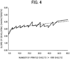
FIG. 4 is a graph illustrating an example of changes in developing characteristic with increase in the number of printed sheets; -
FIGS. 5A to 5D are diagrams illustrating examples of dot patterns of some pixels with some pixel thinning rates; -
FIG. 6 is a graph illustrating a pixel thinning rate control with the increase in the number of printed sheets, according to an embodiment of the present disclosure; -
FIG. 7A is a graph illustrating toner consumption in a comparative example; -
FIG. 7B is a graph illustrating toner consumption in the embodiment of the present disclosure; -
FIG. 8 is a graph illustrating a relation between amounts of developer conveyed on a developing roller and pixel thinning rates; and -
FIG. 9 is a flowchart illustrating procedures of the pixel thinning rate control. - The accompanying drawings are intended to depict embodiments of the present disclosure and should not be interpreted to limit the scope thereof. The accompanying drawings are not to be considered as drawn to scale unless explicitly noted.
- In describing embodiments illustrated in the drawings, specific terminology is employed for the sake of clarity. However, the disclosure of this specification is not intended to be limited to the specific terminology so selected and it is to be understood that each specific element includes all technical equivalents that have a similar function, operate in a similar manner, and achieve a similar result.
- Although the embodiments are described with technical limitations with reference to the attached drawings, such description is not intended to limit the scope of the disclosure and all of the components or elements described in the embodiments of this disclosure are not necessarily indispensable.
- The following is a description of the present disclosure with reference to attached drawings. In the drawings for explaining the present disclosure, identical reference numerals are assigned to elements such as members and parts that have an identical function or an identical shape as long as differentiation is possible, and a description of those elements is omitted once the description is provided.
- Hereinafter, an image forming apparatus according to embodiments of the present disclosure are described in detail with reference to the accompanying drawings. The image forming apparatus according to the present embodiment forms images by an electrophotographic method and has the following features in an image density control to reduce toner consumption. In short, the image forming apparatus according to the present embodiment uses a characteristic that the increase in the number of printed sheets darkens the image and increases a pixel thinning rate with the increase in the number of printed sheets to maintain a constant image density and save toner consumption.
-
FIG. 1 is a schematic cross-sectional view illustrating a configuration of animage forming apparatus 1000 including a developer replenishment control system. Theimage forming apparatus 1000 is a monochrome image forming apparatus including anapparatus body 100 in which aprocess unit 1 as an image forming unit is removably installed. Theprocess unit 1 includes aphotoconductor 2 as an image bearer to bear images on a surface of thephotoconductor 2, acharging roller 3 as a charger to charge the surface of thephotoconductor 2, a developingdevice 4 to develop a latent image on thephotoconductor 2 into a visible image, and acleaning blade 5 as a cleaner to clean the surface of thephotoconductor 2. In addition, theprocess unit 1 includes atoner cartridge 7 as a storage unit that stores toner as a developer. Thetoner cartridge 7 is detachably attached to theprocess unit 1. - The
toner cartridge 7 includes atoner container 8 to store toner supplied to an image forming portion of the developingdevice 4 and a toner collection container 9 to collect waste toner removed by thecleaning blade 5. Thetoner container 8 and the toner collection container 9 integrally form acontainer body 22. The developingdevice 4 in the present embodiment uses one-component developer including toner particles and not including carrier. Additionally, for example, toner used in the present embodiment is polyester toner including polyester resin mother particles. - The
image forming apparatus 1000 further includes a light-emitting diode (LED)head array 6 as an exposure device to expose the surface of thephotoconductor 2, disposed facing thephotoconductor 2. In addition to theprocess unit 1, theimage forming apparatus 1000 includes atransfer device 10, asheet feeder 11, afixing device 12, and anoutput device 13. Thetransfer device 10 transfers an image onto a sheet P as a recording medium. The sheet feeder 11 feeds or supplies the sheet P. Thefixing device 12 fixes the transferred image onto the sheet P. Theoutput device 13 ejects the sheet P outside theapparatus body 100. The sheets P may be thick paper, post cards, envelopes, plain paper, thin paper, coated paper, art paper, tracing paper, or the like. The sheets P as recording media may be overhead projector (OHP) transparencies (OHP sheets). - The
transfer device 10 includes atransfer roller 14 as a transfer member. Thetransfer roller 14 is in contact with thephotoconductor 2 when theprocess unit 1 is installed in theapparatus body 100 of theimage forming apparatus 1000. A transfer nip region is formed at a contact part at which thephotoconductor 2 and thetransfer roller 14 contact to each other. Thetransfer roller 14 is applied with at least one of a predetermined direct current (DC) voltage and a predetermined alternating current (AC) voltage. Thesheet feeder 11 includes asheet tray 15 that loads a plurality of sheets P and afeed roller 16 that feeds an uppermost sheet P of the plurality of sheets P loaded on thesheet tray 15 toward aregistration roller pair 17. Theregistration roller pair 17 is disposed downstream from thefeed roller 16 in a conveyance direction of the sheet P. Theregistration roller pair 17 functions as a timing roller pair to convey the sheet P to a transfer nip region at a proper timing of conveyance of the sheet P. - The
fixing device 12 includes afixing roller 18 as a fixing member and apressure roller 19 as a pressure member. A heater heats thefixing roller 18. Thepressure roller 19 is pressed against and contacts the fixingroller 18 to form a fixing nip in the area of contact between thepressure roller 19 and the fixingroller 18. Theoutput device 13 includes anoutput roller pair 20. Theoutput roller pair 20 ejects the sheet P outside theapparatus body 100. The ejected sheet P is stacked on anoutput tray 21 that is a partly recessed upper face of theapparatus body 100. The developer replenishment control system may be configured by thetoner cartridge 7, the developingdevice 4, a remaining amount detector that detects a remaining amount of the developer remaining in the image forming portion of the developingdevice 4, and acontroller 900 that controls an amount of the developer supplied from the storage unit to the image forming portion of the developingdevice 4. -
FIG. 2 is a schematic explanatory view illustrating attachment/detachment of aprocess unit 1 to/from theapparatus body 100 of theimage forming apparatus 1000. In theimage forming apparatus 1000, an openable andclosable cover 101 is provided on a rear side of theapparatus body 100. Opening thecover 101 causes a link mechanism to retract the light-emittingdiode head array 6 upward. The above-described configuration enables an operator to open thecover 101 and remove theprocess unit 1 from the rear side (or right or left side) of theapparatus body 100 avoiding the interference between the light-emittingdiode head array 6 and theprocess unit 1. In the present embodiment, theprocess unit 1 attached thetoner cartridge 7, as one unit, can be installed in or removed from the rear side (or the right or left side) of theapparatus body 100. Thetoner cartridge 7 is attachable to and detachable from theprocess unit 1 both when theprocess unit 1 is installed in theapparatus body 100 and when theprocess unit 1 is removed from theapparatus body 100. -
FIG. 3 is a schematic cross-sectional view illustrating a configuration of the developingdevice 4 provided in theprocess unit 1 of theimage forming apparatus 1000. The developingdevice 4 provided in theprocess unit 1 includes adevelopment housing 30 that accommodates toner, and a developingroller 31 as a developer bearer to bear toner. Thedevelopment housing 30 can be regarded as an image forming portion of the developingdevice 4. In addition, the developingdevice 4 includes asupply roller 32 as a developer supplier to supply toner to the developingroller 31, adoctor blade 33 as a regulator to regulate an amount of toner borne on the developingroller 31, afirst developer conveyor 34, and asecond developer conveyor 35. Thefirst developer conveyor 34 and thesecond developer conveyor 35 convey the toner. - The developing
roller 31 rotates counterclockwise inFIG. 3 as indicated an arrow illustrated inFIG. 3 and transports developer carried thereon to a position facing thedoctor blade 33 and a position facing thephotoconductor 2. Thesupply roller 32 abuts against the developingroller 31 and supplies toner in thedevelopment housing 30 to a surface layer of the developingroller 31 by rotating counterclockwise inFIG. 3 , that is, in a direction counter to the direction of rotation of the developingroller 31. In the present embodiment, the ratio of rotational frequency of thesupply roller 32 to that of the developingroller 31 is 1 so that toner can be supplied reliably. One end of thedoctor blade 33 is in contact with a surface of the developingroller 31, forming a regulation nip therebetween. While toner supplied to the developingroller 31 by thesupply roller 32 passes through the regulation nip between the developingroller 31 and thedoctor blade 33, the amount of toner is adjusted. Simultaneously, toner is charged by friction. - A
toner cartridge 7 contains fresh toner to be supplied and is detachably attached to an upper portion of thedevelopment housing 30. Therefore, the upper portion of thedevelopment housing 30 has asupply port 30a to supply the toner in thetoner cartridge 7 into thedevelopment housing 30. - The toner is supplied to the
development housing 30 according to detection results by a remaining amount detecting sensor as the remaining amount detector configured to detect an amount of toner remaining in thedevelopment housing 30. That is, when the remaining amount detecting sensor detects that the toner has been consumed in thedevelopment housing 30 and the toner amount has become equal to or less than a predetermined value, thetoner cartridge 7 is driven for a predetermined time. As a result, a predetermined amount of toner is supplied to thedevelopment housing 30. When the predetermined amount of toner is supplied to thedevelopment housing 30, thecontroller 900 as a control device provided in theimage forming apparatus 1000 adjusts a driving amount of a driving mechanism based on a remaining amount lower limit value, a remaining amount upper limit value, which are predetermined, and the remaining amount of toner detected by the remaining amount detecting sensor and drives the drive mechanism. As a result, thecontroller 900 controls the amount of toner supplied from thetoner cartridge 7 as the storage unit to the image forming portion of the developing device 4 (the development housing 30). - A
partition 36 substantially parallel to an axis direction of the developingroller 31 is disposed inside thedevelopment housing 30. Thepartition 36 divides, but not completely, thedevelopment housing 30 into a first compartment A including thesupply port 30a and a second compartment B including the developingroller 31, thedoctor blade 33, and the like. Thepartition 36 extends in the vertical direction. The first compartment A and the second compartment B are arranged horizontally adjacent to each other. Thefirst developer conveyor 34 is disposed in the first compartment A, and thesecond developer conveyor 35 is disposed in the second compartment B. The developingdevice 4 and thetoner cartridge 7 may be configured as one unit. - The
image forming apparatus 1000 according to the present embodiment, that is, for example, an inexpensive small printer uses the characteristic that the increase in the number of printed sheets darkens the image and performs control that increases a pixel thinning rate step by step with the increase in the number of printed sheets. The above-described control can keep the image density constant and reduce the toner consumption. - Specifically, the
supply roller 32 formed of a single foam silicon material has a high developer supply performance. As illustrated inFIG. 4 , in thesupply roller 32, the increase in the number of printed sheets causes an increase in the amount of the developer conveyed onto the developingroller 31. The increase in the amount of the developer on the developingroller 31 causes an increase in a slope of the developing characteristic and increases the image density. The reason why thesupply roller 32 formed of the single foam silicon material is used is that a high developer supply performance gives good followability in printing a lot of solid images. - The
controller 900 performs a pixel thinning rate control as illustrated inFIGS. 5A to 5D andFIG. 6 when the image density increases as described above. In the pixel thinning rate control, thecontroller 900 thins out a pixel (for example, a solid pixel) having a predetermined image density or higher from the image in units of one dot or a plurality of predetermined number of dots forming the image. The pixel thinning rate control enables thecontroller 900 to adjust the image density to keep the image density constant and reduce the toner consumption.FIGS. 5A to 5D illustrate examples of pixels each of which is configured by four dots in a vertical direction by four dots in a horizontal direction after the pixel thinning rate control is performed based on the image density. In the pixel thinning rate control, the pixels forming the image are thinned based on pixel thinning rates, for example, as illustrated inFIG. 5A illustrating an image with 0% pixel thinning rate,FIG. 5B illustrating an image with 25% pixel thinning rate,FIG. 5C illustrating an image with 50% pixel thinning rate, andFIG. 5D illustrating an image with 75% pixel thinning rate. - As illustrated in
FIG. 6 , thecontroller 900 performs the above-described pixel thinning rate control so that the pixel thinning rate becomes higher as the number of printed sheets increases. Thecontroller 900 counts up the number of printed sheets when the image is formed on thephotoconductor 2 in a Photo Conductor Drum Unit (PCDU). InFIG. 6 , apixel thinning rate 601 means 0% pixel thinning rate as illustrated inFIG. 5A . As the number of images formed on thephotoconductor 2 increases, thecontroller 900 increases the pixel thinning rate, for example, thepixel thinning rate 602 → thepixel thinning rate 603 → thepixel thinning rate 604 inFIG. 6 . InFIG. 6 , thepixel thinning rate 602 means 25% pixel thinning rate as illustrated inFIG. 5B , thepixel thinning rate 603 means 50% pixel thinning rate as illustrated inFIG. 5C , and thepixel thinning rate 604 means 75% pixel thinning rate as illustrated inFIG. 5D . Performing the above-described pixel thinning rate control results in an increase of yield that is the number of sheets having images that one toner cartridge can print. -
FIG. 7A is a graph illustrating toner consumption in a comparative example in which thecontroller 900 does not perform the pixel thinning rate control, andFIG. 7B is a graph illustrating toner consumption in the present embodiment in which thecontroller 900 performs the pixel thinning rate control. InFIGS. 7A and 7B , the horizontal axis represents the number of printed sheets, and the vertical axis represents the toner amount (g) in the toner cartridge.FIG. 7A illustratestoner consumption 701a for the first toner cartridge,toner consumption 702a for the second toner cartridge,toner consumption 703a for the third toner cartridge,toner consumption 704a for the fourth toner cartridge, andtoner consumption 705a for the fifth toner cartridge when thecontroller 900 does not perform the pixel thinning rate control. As illustrated inFIG. 7A , as the number of consumed toner cartridges increases, the number of printed sheets per one toner cartridge, that is, the yield decreases. -
FIG. 7B illustratestoner consumption 701b for the first toner cartridge,toner consumption 702b for the second toner cartridge,toner consumption 703b for the third toner cartridge,toner consumption 704b for the fourth toner cartridge, andtoner consumption 705b for the fifth toner cartridge when thecontroller 900 performs the pixel thinning rate control. Thecontroller 900 according to the present embodiment performs the pixel thinning rate control so that the toner consumption amount is kept constant even when the number of printed sheets increases. Therefore, as illustrated inFIG. 7B , even when the number of consumed toner cartridges increases, the number of printed sheets per one toner cartridge, that is, the yield does not decrease. That is, the pixel thinning rate control performed by thecontroller 900 according to the present embodiment can improve the yield. -
FIG. 8 is a graph illustrating an example of a relation between amounts of developer conveyed on the developing roller and pixel thinning rates. As illustrated inFIG. 8 , in the present embodiment, thecontroller 900 determines the pixel thinning rate based on the amount of developer conveyed on the developing roller. For example, inFIG. 8 , thecontroller 900 does not perform the pixel thinning rate control when the amount of developer conveyed on the developing roller is equal to or smaller than 0.80 mg/cm2 that is a threshold, and as the amount of developer conveyed on the developing roller increases, thecontroller 900 increases the pixel thinning rate. Thecontroller 900 may calculate the image density based on a detection result of a film thickness of the photoconductor, the number of the printed sheets, and an environment and change the pixel thinning rate based on the calculated image density. As the number of printed sheets increases, the amount of developer conveyed on the developing roller changes, and the image density increases. Since the above-described control changes the pixel thinning rate based on the increase in the image density, the controller can visually keep the image density constant and improve the yield. -
FIG. 9 is a flowchart illustrating procedures of the pixel thinning rate control. The pixel thinning rate control is performed by, for example, thecontroller 900 that controls the entireimage forming apparatus 1000. In the present embodiment, thecontroller 900 is disposed in theimage forming apparatus 1000 and performs the pixel thinning rate control. Alternatively, thecontroller 900 may be disposed in theprocess unit 1 or the developingdevice 4 and perform control of operations of theprocess unit 1 or the developingdevice 4 in addition to the pixel thinning rate control. - The
controller 900 may be general hardware configured by a processor such as a central processing unit (CPU). The processor executes a program to perform the above-described control. Note that the main part that executes the program to perform the control may be the processor including a dedicated circuit, for example, a Field-Programmable Gate Array (FPGA) or an Application Specific Integrated Circuit (ASIC) to perform specific processing. - As illustrated in
FIG. 9 , when thecontroller 900 in the present embodiment starts printing, thecontroller 900 checks a travel distance of thephotoconductor 2 in the PCDU in step S902. In step S903, thecontroller 900 calculates the amount of developer conveyed on the developing roller. To calculate the amount of developer conveyed on the developing roller, for example, thecontroller 900 may read a value detected by a density sensor and multiply the value by the travel distance of thephotoconductor 2. Alternatively, thecontroller 900 may store the amount of developer conveyed on the developing roller according to the traveling distance of thephotoconductor 2 as a table in advance and read the table to obtain the amount of developer conveyed on the developing roller. - In step S904, the
controller 900 determines whether the traveling distance after thetoner cartridge 7 is replaced is equal to or greater than a threshold value. When thecontroller 900 determines that the traveling distance after thetoner cartridge 7 is replaced is equal to or greater than the threshold value (Yes in step S904), thecontroller 900 proceeds the control to step S906. On the other hand, when thecontroller 900 determines that the traveling distance after thetoner cartridge 7 is replaced is not equal to or greater than the threshold value (No in step S904), thecontroller 900 proceeds the control to step S905. Thecontroller 900 obtains the traveling distance from the usage history of thetoner cartridge 7. The usage history is the history when theprocess unit 1 is operated using thetoner cartridge 7 such as the number of printed sheets at a toner end, the average number of printed sheets per one job (P/J), and a printing rate in addition to the above-described traveling distance. The number of printed sheets at the toner end is the number of sheets printed from the first use of thetoner cartridge 7 to immediately before replacement of thetoner cartridge 7. The average number of printed sheets per one job (P/J) is an average value of the number of sheets printed continuously using thetoner cartridge 7. For example, when theimage forming apparatus 1000 continuously prints five sheets 500 times, continuously prints threesheets 1000 times, and prints only one sheet 2000 times, the average number of printed sheets per one job (P/J) is (5 × 500 +3 × 1000 + 1 × 2500) / (500 + 1000 + 2500) = 1.5. The printing rate is the ratio of a printing area per one sheet area. The usage history is stored in, for example, a memory held by thecontroller 900. - In step S905, the
controller 900 reads the usage history of thetoner cartridge 7 before the replacement of thetoner cartridge 7, that is, the usage history of thetoner cartridge 7 in the previous generation from the memory and estimates an increase in the amount of developer conveyed on the developing roller. The following is the reason for making the above-described estimation in S905. There is little toner in theprocess unit 1 immediately before the replacement of thetoner cartridge 7. Therefore, a lot of toner is supplied to theprocess unit 1 that had little toner for a while immediately after the replacement of thetoner cartridge 7. Supplying a lot of toner temporarily increases the amount of developer conveyed on the developing roller, which is different from an original amount of developer conveyed on the developing roller. - After step S905, in step S906, the
controller 900 determines the pixel thinning rate used for image correction based on the amount of developer conveyed on the developing roller estimated in S905. When thecontroller 900 determines that the traveling distance after thetoner cartridge 7 is replaced is equal to or greater than the threshold value (Yes in step S904), in step S906, thecontroller 900 determines the pixel thinning rate used for image correction based on the amount of developer conveyed on the developing roller calculated in S903. Finally, thecontroller 900 completes the control flow according to the present embodiment. To determine the pixel thinning rate based on the amount of developer conveyed on the developing roller in step S906, for example, the memory may store the graph data illustrated inFIG. 8 , and thecontroller 900 may read the data and calculate the pixel thinning rate. - The developing
device 4 in the present embodiment includes the developingroller 31 as the developer bearer to bear the developer and thesupply roller 32 as the developer supplier to supply the developer supplied from a container such as thetoner container 8 to the developer bearer, and thecontroller 900 performs the pixel thinning rate control that thins out the pixel having the predetermined image density or higher based on the amount of developer conveyed on the developing bearer. The above-describedimage forming apparatus 1000 can adjust the image density and improve the yield because thecontroller 900 performs the pixel thinning rate control that increases the pixel thinning rate based on the increase in the image density, that is, the increase in the amount of developer conveyed on the developing roller. For example, the inexpensive small printer has the characteristic that the increase in the number of printed sheets darkens the image. Using this characteristic and increasing the pixel thinning rate step by step can keep the image density constant and reduce the toner consumption. In theimage forming apparatus 1000 according to the present embodiment, since thecontroller 900 automatically determines the pixel thinning rate corresponding to the image density during printing, the user does not need to set the pixel thinning rate that is a troublesome operation, and the life of the toner cartridge can be lengthened. - The
controller 900 performs the pixel thinning rate control that changes the pixel thinning rate of the pixel based on the number of printed sheets at the toner end that is the number of sheets printed from the first use of thenew toner cartridge 7 to immediately before replacement of the usedtoner cartridge 7. For example, thecontroller 900 reads the usage history of thetoner cartridge 7 one cycle before, from the memory, and changes the pixel thinning rate based on the number of printed sheets at the toner end that is included in the usage history. The pixel thinning rate corresponding to the number of printed sheets at the toner end may be held in the table stored in the memory. Changing the pixel thinning rate based on the number of printed sheets at the toner end that is included in the usage history of the usedtoner cartridge 7 that is the actual data can more accurately stabilize the image density. - The
controller 900 calculates a print characteristic value of the container based on the number of printed sheets at the toner end and the average value of the number of sheets printed continuously using thetoner cartridge 7, that is, the average number of printed sheets per one job (P/J) and performs the pixel thinning rate control based on the calculated print characteristic value of the container. For example, thecontroller 900 calculates a value obtained by dividing the number of printed sheets at the toner end by the average number of printed sheets per one job (P/J) and changes the pixel thinning rate based on the value. The pixel thinning rate corresponding to the value may be held in the table stored in the memory. Changing the pixel thinning rate based on the value that is calculated from the actual data included in the usage history of the usedtoner cartridge 7 can more accurately stabilize the image density. - Alternatively, the
controller 900 may calculate a print characteristic value of the container based on the number of printed sheets at the toner end and the printing rate that is the ratio of a printing area per one sheet area and performs the pixel thinning rate control based on the calculated print characteristic value of the container. For example, thecontroller 900 calculates a value obtained by multiplying the printing rate by the number of printed sheets at the toner end and changes the pixel thinning rate based on the value. The pixel thinning rate corresponding to the value may be held in the table stored in the memory. Changing the pixel thinning rate based on the value that is calculated from the actual data included in the usage history of the usedtoner cartridge 7 can more accurately stabilize the image density. The control that changes the pixel thinning rate using these actual data may be appropriately combined and used if necessary. - The developer supplier is formed of a single foam silicon material. As the number of the printed sheets increases, the slope of the developing characteristic in the developing device using the developer supplier increases, and the image density increases. The cells of the developer supplier may have a diameter of 200 to 300 µm. For example, it is preferable to use the developer supplier having a foamed elastic layer such as a single foam silicon material layer having an average cell diameter of 200 to 300 µm. In the measurement of the cell diameter, a microscope is generally used. In the calculation of the average cell diameter, cell diameters are measured at 100 to 500 points, and the average sell diameter is calculated. The above-described configuration can improve a supply property without toner blocking during continuous printing.
- Preferably, the developing device uses the developer made by a pulverization method, and the controller performs the pixel thinning rate control because the developer made by the pulverization method has wide material selectivity and is easy to adjust a charging ability. In addition, since the shape of the toner made by the pulverization method is irregular, the toner easily adheres to the supply roller.
- Additionally, the
controller 900 may perform the pixel thinning rate control in a solid image portion having a predetermined area or more. The above-described control can control the image density and prevent letters and thin lines from blurring. - The present disclosure has been described as above on the basis of preferred embodiments. The present disclosure is not limited to the description in the above embodiments, and various modifications may be made without departing from the scope and spirit of the present disclosure.
- Numerous additional modifications and variations are possible in light of the above teachings. It is therefore to be understood that, within the scope of the above teachings, the present disclosure may be practiced otherwise than as specifically described herein. With some embodiments having thus been described, it will be obvious that the same may be varied in many ways. Such variations are not to be regarded as a departure from the scope of the present disclosure and appended claims, and all such modifications are intended to be included within the scope of the present disclosure and appended claims.
Claims (8)
- An image forming apparatus (1000) comprising:a developer bearer (31) configured to bear developer;a container (8) configured to contain the developer;a developer supplier (32) configured to supply the developer supplied from the container (8) to the developer bearer (31); anda controller (900) configured to perform a pixel thinning rate control to thin out a pixel based on an amount of the developer conveyed on the developer bearer (31).
- The image forming apparatus (1000) according to claim 1,
wherein the controller (900) is configured to change a pixel thinning rate of the pixel based on a number of printed sheets at a toner end that is a cumulative number of sheets printed from a first use of the container to immediately before replacement of the container. - The image forming apparatus according to claim 2,
wherein the controller (900) is configured to calculate a print characteristic value of the container (8) based on the number of printed sheets at the toner end and an average number of printed sheets per one job while the container (8) is used and change the pixel thinning rate of the pixel based on the print characteristic value of the container (8). - The image forming apparatus (1000) according to claim 2 or 3,
wherein the controller (900) is configured to calculate a print characteristic value of the container (8) based on the number of printed sheets at the toner end and a printing rate and change the pixel thinning rate of the pixel based on the print characteristic value of the container (8). - The image forming apparatus (1000) according to any one of claims 1 to 4,
wherein the developer supplier is formed of a single foam silicon material. - The image forming apparatus (1000) according to claim 5
wherein a cell of the developer supplier (32) has a diameter of 200 to 300 µm. - The image forming apparatus (1000) according to any one of claims 1 to 6,
wherein the developer is made by a pulverization method. - The image forming apparatus (1000) according to any one of claims 1 to 7,
wherein the controller (900) is configured to perform the pixel thinning rate control on a solid image portion having a predetermined area or more.
Applications Claiming Priority (1)
| Application Number | Priority Date | Filing Date | Title |
|---|---|---|---|
| JP2019177137A JP7447416B2 (en) | 2019-09-27 | 2019-09-27 | Developing device and image forming device |
Publications (1)
| Publication Number | Publication Date |
|---|---|
| EP3798733A1 true EP3798733A1 (en) | 2021-03-31 |
Family
ID=72355862
Family Applications (1)
| Application Number | Title | Priority Date | Filing Date |
|---|---|---|---|
| EP20194290.1A Withdrawn EP3798733A1 (en) | 2019-09-27 | 2020-09-03 | Image forming apparatus |
Country Status (2)
| Country | Link |
|---|---|
| EP (1) | EP3798733A1 (en) |
| JP (1) | JP7447416B2 (en) |
Citations (7)
| Publication number | Priority date | Publication date | Assignee | Title |
|---|---|---|---|---|
| US5655197A (en) * | 1992-06-02 | 1997-08-05 | Seiko Epson Corporation | Developing device |
| JPH11254753A (en) * | 1998-03-06 | 1999-09-21 | Ricoh Co Ltd | Printer |
| US6266153B1 (en) * | 1998-05-12 | 2001-07-24 | Xerox Corporation | Image forming device having a reduced toner consumption mode |
| JP2001324835A (en) * | 2000-05-15 | 2001-11-22 | Minolta Co Ltd | Yellow toner for development of electrostatic latent image and method for forming image |
| JP2007108623A (en) * | 2005-09-14 | 2007-04-26 | Ricoh Co Ltd | Image forming apparatus |
| US20160091851A1 (en) * | 2014-09-26 | 2016-03-31 | Kyocera Document Solutions Inc. | Image Forming Apparatus That Reduces Variation of Count of Printable Sheets per Toner Container, Image Forming Method, and Recording Medium |
| JP2018010230A (en) | 2016-07-15 | 2018-01-18 | 株式会社リコー | Image forming apparatus and method for controlling image forming apparatus |
Family Cites Families (4)
| Publication number | Priority date | Publication date | Assignee | Title |
|---|---|---|---|---|
| JP5815994B2 (en) | 2011-06-03 | 2015-11-17 | 株式会社ブリヂストン | Developing roller |
| JP6096425B2 (en) | 2012-05-29 | 2017-03-15 | 株式会社ブリヂストン | Manufacturing method of toner supply roller |
| JP6248907B2 (en) | 2014-11-25 | 2017-12-20 | 京セラドキュメントソリューションズ株式会社 | Image forming apparatus |
| JP6890772B2 (en) | 2018-01-19 | 2021-06-18 | 京セラドキュメントソリューションズ株式会社 | Image forming apparatus, image forming method and image forming program |
-
2019
- 2019-09-27 JP JP2019177137A patent/JP7447416B2/en active Active
-
2020
- 2020-09-03 EP EP20194290.1A patent/EP3798733A1/en not_active Withdrawn
Patent Citations (7)
| Publication number | Priority date | Publication date | Assignee | Title |
|---|---|---|---|---|
| US5655197A (en) * | 1992-06-02 | 1997-08-05 | Seiko Epson Corporation | Developing device |
| JPH11254753A (en) * | 1998-03-06 | 1999-09-21 | Ricoh Co Ltd | Printer |
| US6266153B1 (en) * | 1998-05-12 | 2001-07-24 | Xerox Corporation | Image forming device having a reduced toner consumption mode |
| JP2001324835A (en) * | 2000-05-15 | 2001-11-22 | Minolta Co Ltd | Yellow toner for development of electrostatic latent image and method for forming image |
| JP2007108623A (en) * | 2005-09-14 | 2007-04-26 | Ricoh Co Ltd | Image forming apparatus |
| US20160091851A1 (en) * | 2014-09-26 | 2016-03-31 | Kyocera Document Solutions Inc. | Image Forming Apparatus That Reduces Variation of Count of Printable Sheets per Toner Container, Image Forming Method, and Recording Medium |
| JP2018010230A (en) | 2016-07-15 | 2018-01-18 | 株式会社リコー | Image forming apparatus and method for controlling image forming apparatus |
Also Published As
| Publication number | Publication date |
|---|---|
| JP7447416B2 (en) | 2024-03-12 |
| JP2021056303A (en) | 2021-04-08 |
Similar Documents
| Publication | Publication Date | Title |
|---|---|---|
| US9069284B2 (en) | Image forming apparatus and powder transport unit | |
| US8688014B2 (en) | Image forming apparatus | |
| US20110222872A1 (en) | Image forming apparatus | |
| JP2009116001A (en) | Method and device for estimating toner residual amount, and image forming apparatus | |
| JP4781064B2 (en) | Image forming apparatus | |
| JP2006227325A (en) | Image forming apparatus | |
| EP3798733A1 (en) | Image forming apparatus | |
| JP2010128400A (en) | Image forming apparatus | |
| US10775716B2 (en) | Image forming unit and image forming apparatus | |
| US20090116858A1 (en) | Developing device and image forming apparatus including the same | |
| JP2008065128A (en) | Image forming method and image forming apparatus | |
| JP2004170946A (en) | Image forming apparatus and method for detecting residual quantity of developer in image forming apparatus | |
| JP5960516B2 (en) | Developing device and image forming apparatus | |
| JP2004198544A (en) | Image forming apparatus | |
| JP6984219B2 (en) | Developer replenishment control system, image forming device, and developer replenishment control method | |
| JP2003195620A (en) | Image forming apparatus | |
| JP5734028B2 (en) | Image forming apparatus | |
| JP5428207B2 (en) | Image density control method and image forming apparatus in development | |
| JP2020016783A (en) | Image forming apparatus | |
| JPH04473A (en) | Developer container for developing device | |
| JP3794526B2 (en) | Image forming apparatus and control method thereof | |
| US11126110B2 (en) | Image forming apparatus for controlling durability correction value in execution of toner installation mode | |
| JP2001356670A (en) | Image forming device, process cartridge and storage medium | |
| JP2009181114A (en) | Image forming apparatus and density control method for the image forming apparatus | |
| KR100485863B1 (en) | Voltage regulator for picture processor, and voltage controlling method thereof |
Legal Events
| Date | Code | Title | Description |
|---|---|---|---|
| PUAI | Public reference made under article 153(3) epc to a published international application that has entered the european phase |
Free format text: ORIGINAL CODE: 0009012 |
|
| STAA | Information on the status of an ep patent application or granted ep patent |
Free format text: STATUS: REQUEST FOR EXAMINATION WAS MADE |
|
| 17P | Request for examination filed |
Effective date: 20200903 |
|
| AK | Designated contracting states |
Kind code of ref document: A1 Designated state(s): AL AT BE BG CH CY CZ DE DK EE ES FI FR GB GR HR HU IE IS IT LI LT LU LV MC MK MT NL NO PL PT RO RS SE SI SK SM TR |
|
| AX | Request for extension of the european patent |
Extension state: BA ME |
|
| STAA | Information on the status of an ep patent application or granted ep patent |
Free format text: STATUS: THE APPLICATION HAS BEEN WITHDRAWN |
|
| 18W | Application withdrawn |
Effective date: 20220504 |