EP3798700A2 - Verriegelbarer mpo-verbinder zur sicherung in einem anschluss eines adapters mit einem einmaligen entnahmeschlüssel - Google Patents
Verriegelbarer mpo-verbinder zur sicherung in einem anschluss eines adapters mit einem einmaligen entnahmeschlüssel Download PDFInfo
- Publication number
- EP3798700A2 EP3798700A2 EP20197897.0A EP20197897A EP3798700A2 EP 3798700 A2 EP3798700 A2 EP 3798700A2 EP 20197897 A EP20197897 A EP 20197897A EP 3798700 A2 EP3798700 A2 EP 3798700A2
- Authority
- EP
- European Patent Office
- Prior art keywords
- key
- mpo
- lockable
- adapter
- connector
- Prior art date
- Legal status (The legal status is an assumption and is not a legal conclusion. Google has not performed a legal analysis and makes no representation as to the accuracy of the status listed.)
- Withdrawn
Links
Images


Classifications
-
- G—PHYSICS
- G02—OPTICS
- G02B—OPTICAL ELEMENTS, SYSTEMS OR APPARATUS
- G02B6/00—Light guides; Structural details of arrangements comprising light guides and other optical elements, e.g. couplings
- G02B6/24—Coupling light guides
- G02B6/36—Mechanical coupling means
- G02B6/38—Mechanical coupling means having fibre to fibre mating means
- G02B6/3807—Dismountable connectors, i.e. comprising plugs
- G02B6/381—Dismountable connectors, i.e. comprising plugs of the ferrule type, e.g. fibre ends embedded in ferrules, connecting a pair of fibres
- G02B6/3825—Dismountable connectors, i.e. comprising plugs of the ferrule type, e.g. fibre ends embedded in ferrules, connecting a pair of fibres with an intermediate part, e.g. adapter, receptacle, linking two plugs
-
- G—PHYSICS
- G02—OPTICS
- G02B—OPTICAL ELEMENTS, SYSTEMS OR APPARATUS
- G02B6/00—Light guides; Structural details of arrangements comprising light guides and other optical elements, e.g. couplings
- G02B6/24—Coupling light guides
- G02B6/36—Mechanical coupling means
- G02B6/38—Mechanical coupling means having fibre to fibre mating means
- G02B6/3807—Dismountable connectors, i.e. comprising plugs
- G02B6/381—Dismountable connectors, i.e. comprising plugs of the ferrule type, e.g. fibre ends embedded in ferrules, connecting a pair of fibres
- G02B6/3818—Dismountable connectors, i.e. comprising plugs of the ferrule type, e.g. fibre ends embedded in ferrules, connecting a pair of fibres of a low-reflection-loss type
- G02B6/3821—Dismountable connectors, i.e. comprising plugs of the ferrule type, e.g. fibre ends embedded in ferrules, connecting a pair of fibres of a low-reflection-loss type with axial spring biasing or loading means
-
- G—PHYSICS
- G02—OPTICS
- G02B—OPTICAL ELEMENTS, SYSTEMS OR APPARATUS
- G02B6/00—Light guides; Structural details of arrangements comprising light guides and other optical elements, e.g. couplings
- G02B6/24—Coupling light guides
- G02B6/36—Mechanical coupling means
- G02B6/38—Mechanical coupling means having fibre to fibre mating means
- G02B6/3807—Dismountable connectors, i.e. comprising plugs
- G02B6/381—Dismountable connectors, i.e. comprising plugs of the ferrule type, e.g. fibre ends embedded in ferrules, connecting a pair of fibres
- G02B6/3826—Dismountable connectors, i.e. comprising plugs of the ferrule type, e.g. fibre ends embedded in ferrules, connecting a pair of fibres characterised by form or shape
-
- G—PHYSICS
- G02—OPTICS
- G02B—OPTICAL ELEMENTS, SYSTEMS OR APPARATUS
- G02B6/00—Light guides; Structural details of arrangements comprising light guides and other optical elements, e.g. couplings
- G02B6/24—Coupling light guides
- G02B6/36—Mechanical coupling means
- G02B6/38—Mechanical coupling means having fibre to fibre mating means
- G02B6/3807—Dismountable connectors, i.e. comprising plugs
- G02B6/3869—Mounting ferrules to connector body, i.e. plugs
- G02B6/387—Connector plugs comprising two complementary members, e.g. shells, caps, covers, locked together
-
- G—PHYSICS
- G02—OPTICS
- G02B—OPTICAL ELEMENTS, SYSTEMS OR APPARATUS
- G02B6/00—Light guides; Structural details of arrangements comprising light guides and other optical elements, e.g. couplings
- G02B6/24—Coupling light guides
- G02B6/36—Mechanical coupling means
- G02B6/38—Mechanical coupling means having fibre to fibre mating means
- G02B6/3807—Dismountable connectors, i.e. comprising plugs
- G02B6/3873—Connectors using guide surfaces for aligning ferrule ends, e.g. tubes, sleeves, V-grooves, rods, pins, balls
- G02B6/3882—Connectors using guide surfaces for aligning ferrule ends, e.g. tubes, sleeves, V-grooves, rods, pins, balls using rods, pins or balls to align a pair of ferrule ends
-
- G—PHYSICS
- G02—OPTICS
- G02B—OPTICAL ELEMENTS, SYSTEMS OR APPARATUS
- G02B6/00—Light guides; Structural details of arrangements comprising light guides and other optical elements, e.g. couplings
- G02B6/24—Coupling light guides
- G02B6/36—Mechanical coupling means
- G02B6/38—Mechanical coupling means having fibre to fibre mating means
- G02B6/3807—Dismountable connectors, i.e. comprising plugs
- G02B6/3873—Connectors using guide surfaces for aligning ferrule ends, e.g. tubes, sleeves, V-grooves, rods, pins, balls
- G02B6/3885—Multicore or multichannel optical connectors, i.e. one single ferrule containing more than one fibre, e.g. ribbon type
-
- G—PHYSICS
- G02—OPTICS
- G02B—OPTICAL ELEMENTS, SYSTEMS OR APPARATUS
- G02B6/00—Light guides; Structural details of arrangements comprising light guides and other optical elements, e.g. couplings
- G02B6/24—Coupling light guides
- G02B6/36—Mechanical coupling means
- G02B6/38—Mechanical coupling means having fibre to fibre mating means
- G02B6/3807—Dismountable connectors, i.e. comprising plugs
- G02B6/389—Dismountable connectors, i.e. comprising plugs characterised by the method of fastening connecting plugs and sockets, e.g. screw- or nut-lock, snap-in, bayonet type
- G02B6/3893—Push-pull type, e.g. snap-in, push-on
-
- G—PHYSICS
- G02—OPTICS
- G02B—OPTICAL ELEMENTS, SYSTEMS OR APPARATUS
- G02B6/00—Light guides; Structural details of arrangements comprising light guides and other optical elements, e.g. couplings
- G02B6/24—Coupling light guides
- G02B6/36—Mechanical coupling means
- G02B6/38—Mechanical coupling means having fibre to fibre mating means
- G02B6/3807—Dismountable connectors, i.e. comprising plugs
- G02B6/389—Dismountable connectors, i.e. comprising plugs characterised by the method of fastening connecting plugs and sockets, e.g. screw- or nut-lock, snap-in, bayonet type
- G02B6/3894—Screw-lock type
-
- G—PHYSICS
- G02—OPTICS
- G02B—OPTICAL ELEMENTS, SYSTEMS OR APPARATUS
- G02B6/00—Light guides; Structural details of arrangements comprising light guides and other optical elements, e.g. couplings
- G02B6/24—Coupling light guides
- G02B6/36—Mechanical coupling means
- G02B6/38—Mechanical coupling means having fibre to fibre mating means
- G02B6/3807—Dismountable connectors, i.e. comprising plugs
- G02B6/3897—Connectors fixed to housings, casing, frames or circuit boards
-
- G—PHYSICS
- G02—OPTICS
- G02B—OPTICAL ELEMENTS, SYSTEMS OR APPARATUS
- G02B6/00—Light guides; Structural details of arrangements comprising light guides and other optical elements, e.g. couplings
- G02B6/24—Coupling light guides
- G02B6/36—Mechanical coupling means
- G02B6/38—Mechanical coupling means having fibre to fibre mating means
- G02B6/3807—Dismountable connectors, i.e. comprising plugs
- G02B6/3898—Tools, e.g. handheld; Tuning wrenches; Jigs used with connectors, e.g. for extracting, removing or inserting in a panel, for engaging or coupling connectors, for assembling or disassembling components within the connector, for applying clips to hold two connectors together or for crimping
-
- G—PHYSICS
- G02—OPTICS
- G02B—OPTICAL ELEMENTS, SYSTEMS OR APPARATUS
- G02B6/00—Light guides; Structural details of arrangements comprising light guides and other optical elements, e.g. couplings
- G02B6/24—Coupling light guides
- G02B6/36—Mechanical coupling means
- G02B6/38—Mechanical coupling means having fibre to fibre mating means
- G02B6/3807—Dismountable connectors, i.e. comprising plugs
- G02B6/3869—Mounting ferrules to connector body, i.e. plugs
Definitions
- the described technology generally relates to lockable connection assemblies configured to provide a secure connection between cable segments, equipment, and/or devices, and, more specifically, to complementary connectors and adapters configured to engage in a locking arrangement that prevents the unintended removal of a connector from an adapter.
- connection assemblies are increasingly being used in harsh environments, including factories, motor vehicles, industrial equipment, military equipment, and on cellular antennae towers.
- conventional connection assemblies often become unintentionally disconnected due to vibration, impact, temperature changes, and exposure to other harsh conditions.
- connection between components may be negatively affected by the ingress of dust, dirt, moisture, and/or other contaminants.
- Fiber optic network segments are particularly vulnerable because fiber optic connections require extremely precise termination and alignment between connected components and cable segments. Accordingly, telecommunication network providers would benefit from a connection assembly capable of maintaining a secure connection and preventing the ingress of unwanted contaminants in harsh environments.
- a lockable MPO connector or a multi-fiber push-on fiber optic connector is locked and unlocked from an adapter using a tool configured to provide one or more locking configurations.
- the lockable MPO connector comprises an inner housing with an inner cavity securing a mechanical transfer ferrule.
- the inner housing is surrounded by an outer housing, where the outer housing is slidable with opposing side slots or openings.
- a rear housing or rear body comprises a shroud or shield that covers the slidable outer housing beyond the side slots, and further read body defines a key passage, where the key passage accepts the tool to unlock an MPO connector from a standard adapter configured to accept the MPO connector inner and outer housing with the mechanical transfer ferrule.
- the rear body shield prevents access to unlock a conventional or prior art MPO connector, as depicted in FIG. 2 from a prior MPO adapter depicted in FIG. 1 .
- a prior art MPO connector is disclosed in U.S. Pat. No. 9,684,139B2 , titled “Optical Fiber Connector with Changeable Gender", to Chang et al., granted June 20, 2017, and owned by the assignee of this application.
- a prior art MPO adapter is disclosed in U.S. Pat. No. 9,798,090B2 , title "Reduced-Profile Data Transmission Element Connectors, Adapters, And Connection Assemblies Thereof', to Takano et al., granted October 24, 2017, and owned by the assignee of this application.
- U.S. Pat. Nos'. 9,684,139B2 and 9,798,090B2 are incorporated by reference into the present application.
- the lockable MPO connector key passage extends through the rear body allowing the unlocking tool to access the slidable outer housing and MPO adapter latches to unlock the MPO connector from the adapter, thereby allowing the MPO connector with rear body to separate from the MPO adapter.
- Each rear body is configured to receive a unique or different key or tool of a particular shape.
- the inner shape of the key passage matches the outer configuration of the tool or key.
- An indicator is marked on the tool so a user can match the unlocking tool with a MPO connector configured to be unlocked with the tool.
- two or more key passages may be deployed as part of the rear body, and the rear body maybe configured to accept structure, such as an external post or protrusion to align the tool or key before inserting the key via the rear body to unlock the MPO connector from the MPO adapter.
- the protrusions may be of different lengths or thickness and even a combination of round and square to ensure the key is properly oriented and aligned before fully inserted the tool or key to perform the unlocking step.
- a key arm extending from a proximal end of the key maybe configured in differing shapes such as round or square, and with cut-outs along the key arm.
- Each key releases a corresponding configured MPO connector from a standard MPO adapter providing lock-out and tag-out security feature for a bank or collection of MPO connectors.
- a tool is used to remove the MPO connector from a standard MPO adapter.
- the disclosed MPO connector in the present invention uses a standard or prior art MPO connector with a rear body that shields the MPO adapter latch arms.
- MPO connectors can be removed from an adapter unintentionally, or become lose during standard use due to the compact arrangement of connector, such as servicing a first connector and the adjacent connector is partially dislodged without the user knowing.
- the lockable MPO connector prevents the MPO connector from being dislodged from its corresponding adapter.
- a tool or key is sized and shaped so a user can grasp the tool, insert properly at a distal end of the rear body, and displace the adapter latch arms from a recess within the inner housing of the MPO connector, so the MPO connector can be removed from the MPO adapter.
- a cleaning tool ss disclosed in U.S. Pub. No. 2018/0267252A1 titled “Gel Stick Cleaner With Reusable Handle And Disposable Cartridge", published September 20, 2018, assigned to the owner of the present application is fully incorporated by reference into the present application.
- a pair of opposing latch arms are formed on at the proximal end of the key body, the latch arms are inserted through openings within the rear body provided the correct key arm or key arms are oriented and inserted into the key passage(s) of the rear body.
- the ley latch arms are is the key arm, instead of a separate set of latch arms and a key arm.
- the opposing key latch arms have hooks facing outward with corresponding chamfers on each side of the hook.
- the key latch arm is called an actuator arm. The chamfers prevent the key latch arms jamming or sticking during key insertion into the rear body, and help guide the opposing hooks into the side slots of the slidable outer housing.
- the key latch arms project from the key body and are configured for releasing adapter latches from the MPO connector, and the key latch arms attach to slots form as part of the MPO outer housing to withdraw the MPO connector assembly (100) (refer to FIG. 9 ) from the MPO adapter. fOnce the opposing hooks are secure within the side slots, the key is pulled rearward. The key pulling the slidable outer housing rearward results in adapter opposing latches to move out from their corresponding recessed locked positon with the adapter latch arms, thereby, separating or removing the MPO connector from the MPO adapter port. A bias member located on an outer surface of slidable outer housing is compressed, as shown in FIG.
- the described technology generally relates to lockable connection assemblies for providing secure connections between cable segments and/or devices within a network.
- the network may include any type of network capable of transmitting signals, electricity, or any other type of transmission medium.
- the network may include, without limitation, a communication network, a telecommunication network, an electrical network, a data network, a computer network, and any combination thereof.
- the network may include a communication network using various signal transmission mediums, including, without limitation, fiber optic networks, Ethernet networks, cable and/or satellite television networks, and any other type of communication network now known or developed in the future.
- the lockable connection assemblies may be configured to connect cable segments and/or devices within a fiber optic network using various standard connector types, including, but not limited to LC, ST, SC, FC, DIN, D4, SMA, E2000, Biconic, FullAXS, OCD, and/or MPO.
- the lockable connection assemblies may be configured to meet various standards, such as the British Standards Institution (BSI), the Open DeviceNet Vendors Association (ODVA), and/or the like.
- the lockable connection assemblies may be used with copper-type network connections, such as RJ-45 type connectors.
- the lockable MPO connector maybe deployed in an array of MPO connectors with the same key lock.
- Each MPO connector rear body has an indicator or letter to the user to identify the corresponding key or removal tool to unlock the MPO connector from a standard MPO adapter.
- the lockable elements help prevent motion of the MPO connector while installed with the MPO adapter, and further helps prevent an unintended removal of the MPO connector from the MPO adapter.
- the arrays of MPO connectors have a cable assembly of the same color. So, as the user works fingers through the group of fibers, moving the fibers can disturb the MPO ferrule endface of the connector increasing insertion losses due to misalignment.
- a more damaging situation can occur when the user pulls on a first MPO connector that has its cable assembly tangled with an adjacent MPO connector that results in the second MPO connector becoming dislodged from the MPO adapter port.
- the lockable MPO connector and its key helps prevent a MPO connector from being dislodged, and further provides some organization within the array by key type to guide the user to unlock the correct MPO connector by key indicator on the rear body.
- the communications network is not disabled which means other MPO connectors are transmitting data.
- connection between connection components may be maintained in harsh environments in which the lockable connection assembly may be subjected to forces due to such as vibrations, impact, temperature change, moisture, wind, or the like.
- the lockable connection assembly may be configured to prevent the ingress of unwanted contaminants into the interior of the lockable connection assembly that may interfere with the connection between the connector and the adaptor.
- the lockable connection assembly may be assembled using relatively low-cost components and locked with minimal labor, thereby providing a cost- and resource-efficient method of providing highly secure connections within a network.
- FIG. 1 depicts a lockable MPO connector assembly (100) secured with a prior art MPO adapter (10).
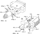
- Lockable MPO connector assembly comprises a rear body (20) or housing (20) (refer to FIG. 7 and FIG. 15 ) and removal tool (50) or key (refer to FIG. 12 , FIGs. 16-19 ).
- Key (50) includes key release (50p.1, 50p.2 (not shown)) when pressed inward or toward the optical axis of the assembly (100), the key releases from rear body (20) when proximal hook (50h.1) is displaced from an opening in the rear body.
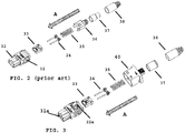
- FIG. 2 depicts an exploded view of prior art MPO connector (70) (refer to FIG. 4 ) assembled in the direction of arrow (A).
- MPO connector comprises inner housing (31) with slidable outer housing (32) about the inner housing.
- Mechanical transfer ferrule (33) is secured within a cavity (31a) formed within the inner housing and pin keep (34) is biased by spring (35) to ensure pins (34p.1, 34p.2) (refer to FIG. 9 ) protrude from a proximal end of the inner housing.
- Rear body (36) is secured within inner housing and holds the ferrule, pin keep and spring assembly together.
- a crimp post (36c) (refer to FIG.
- FIG. 6 depicts an embodiment of MPO connector (80) of the present invention deploying rear body (40) (refer to FIG.7 ), and further comprises slidable outer housing (32) with side slots (40s.1, 40s.2) (refer to FIG. 5 ).
- FIG. 4 depicts prior art MPO connector (70) without side slots or bias member (32a).
- the bias member (32a) is formed as a leaf spring.
- Connector (70) using opposing bias springs (35a, 35b (not shown)) to return slidable outer housing (32) nearer the inner housing (31) proximal end.
- Outer housing (32) covers adapter latch arms (1011. 101.2) (refer to FIG. 10A ) when MPO connector (80) is fully inserted into a port of the MPO adapter.
- the adapter latch arms are received in opposing recesses (31r.1, 31r.2) (not shown in FIG. 5).
- MPO connector (80) depicts MPO connector (80) according to the present invention with opposing side slots (40s.1, 40s.2 (not shown) formed as part of slidable outer housing (32).
- MPO connector (80) deploys bias member (32a), as disclosed in Wong.
- side slots allow of removal tool or key tool access to lock with the slidable outer housing to remove connector (80) from the MPO adapter port (refer to FIG. 13 ).
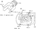
- FIG. 6 depicts prior art rear body (36) comprising body (36b) with a longitudinal bore along the optical axis to receive the optical ribbon cable, and pair opposing latches (361.1, 361.2) that secure rear body (36) to a distal end of inner housing (31) of MPO connector (70).
- Crimp post (36c) secures cable boot (38) by crimp ring (37) or threaded cable boot (not shown).
- Crimp post (36c) may secure the cable jacket or strength members between the crimp ring and the crimp post, as known in the art, to improve pull strength of the cable assembly.
- FIG. 7A depicts a proximal view or front view of rear body (40).
- Rear body (40) comprises flange (40f) and extending away from the flange is shield (40s) formed as a cup.
- Other shield shapes maybe two wings without departing from the scope of the invention.
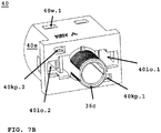
- Windows (40w.1-40w.4) are positioned about the rear body outer housing to provide the user with a visual on far the slidable housing has been moved distally with the key or removal tool and indirectly how much bias member (32a) is compressed. Once fully compressed (refer to FIG. 10B ), the MPO connector (80) is released from the port of the MPO adapter. This allows the user to gauge remaining pull strength without over pulling on the key or removal tool.
- FIG. 7B depicts a distal view of rear body (40) comprising crimp pot (36c) bounded by opposing ley latch arm openings (401o.1, 401o.2) and further bounded by keep passage (40kp. 1, 40kp.2).
- the number of key passage depends on the key to unlock MPO connector (80) from MPO adapter port.
- the rear body can have two key passages (40kp. 1, 40kp.2) and key (50) comprises a first key arm (50k. 1) that differs form a second key arm (50k.2) (refer to FIG. 12 ), to unlock MPO connector (80) from a port of the MPO adapter.
- the first key arm maybe the same as the second key arm without departing from the scope of the invention.
- FIG. 8 depicts assembled MPO connector (80) with rear body (40) at distal end of slidable outer housing (32), the cut-away shows slot (40s. 1) on a first side of the outer housing (32), the second opposing slot (40s.2) is not shown.
- Rear body (40) shield (40s) protects slots (40s. 1, 40s.2) to avoid moving slidable outer housing (32) in a rearward direction to release adapter latch arms (101.1, 101.2) that releases the MPO connector (80) from MPO adapter port.
- FIG. 9 depicts MPO connector (80) assembly (100) with rear body (40) shield (40s) about slidable outer housing (32) biased forward about inner housing (31), under influence of bias member (32a).
- Pin keeper pins (34p. 1, 34p.2) is the proximal end of the MPO connector assembly.
- FIG. 10A to FIG. 10E illustrates the operation of securing the MPO connector (80) with rear body (40) called MPO connector assembly (100) (refer to FIG. 9 ) just prior to insertion, (I), into MPO adapter port defined by latch arms (101.1, 101.2).
- FIG. 10B depicts partial insertion of connector assembly (100).
- bias member is compressed (C) due to adapter latch hooks bend outward and push distally or in rearward direction slidable outer housing (32), until the bias member (32a) is fully compressed.
- FIG. 10C depicts opposing adapter latch arms (101.1 101.2) reaching opposing outer housing slots (32s. 1, 32s.2) (refer to FIG.
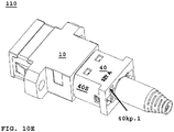
- FIG. 10E depicts MPO connector assembly (100) fully inserted into MPO adapter port (110), with shield (40s) covering any access to slots (40s.1, 40s.2) to removed MPO connector (80) from the adapter port with key (50).
- FIG. 11 depicts a distal or rear view of connector/adapter assembly (110).
- FIG. 11 depicts two key passage (40kp.1, 40kp.2) formed as part of rear body (40) diagonally across from each other, but may be side by side or one above another without departing from the scope of the present invention.
- key indicator (40i) On an outside surface of rear body is key indicator (40i).
- Rear body (40) further comprises key latch arm ports or openings (40o.1, 40o.2).
- FIG. 12 depicts a first embodiment of key (50) or removal tool with key body (50b).
- Key (50) has user grip portion (50g), and flexible arms (501.1, 501.2) that are inserted through rear body openings (40o.1, 40o.2) to displace adapter latch arms to release the MPO connector from the adapter. Flexible latch arms can be pushed inward, along arrow (IN), approximately near pressure point (50p.1, 50p.2) to remove key (50) from MPO connector assembly (100) as shown in FIG. 14E .
- Key (50) further comprise keys (50k.1, 50k.2) sometimes called pattern keys of a particular shape configured to be received with key passage (40kp.1, 40kp.2), which allows latch arms (501.1, 501.2) to displace adapter latch arms to release the MPO connector from the adapter port.
- Key (50) pattern keys are chamfered (50k.2(c)) to reduce jamming and to allow for insertion within binding. The keys differ in size and shape to increase the number of locking combinations, as discussed in FIG. 16 to FIG. 19 .
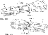
- FIG. 13A to FIG. 13C depicts using a removal tool (50) along arrow (A) into a distal end of rear body (40) secured about MPO connector (80), with latch arms (501) and keys (50k) properly received within rear body (40) to unlock connector from adapter.
- FIG. 13B depicts latch arm (501.1) proximal to slot (40s.1) and key (50k.1) received within key passage (40kp.1).
- FIG. 13C depicts key (50) or removal tool being moved in direction of arrow (A), the key chamfers (50k.1(c)) guide the key (50k.1) within key passage (40kp.1), and chamfers (521.1(c), 521.2(c)) engages the outer housing walls compressing the latch arms (521.1, 521.1) (refer to FIG. 16 ) inward.
- the latch arms of key (50, 52, 54, 56 and 58) FIGs. 12 , 16 , 17 , 18 , 19 ) all have chamfers as shown in FIG. 16 , the chamfers of each key performing the same function discussed above with the outer housing walls.
- FIG. 13D depicts the tool (50) fully inserted and latch arm (5011.1) expands through slot (40s.1).
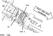
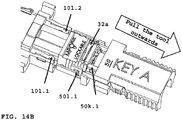
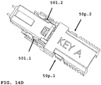
- FIG. 14A through FIG. 14E depicts removing MPO connector assembly (100) from MPO connector/adapter assembly (110).
- FIG. 14A illustrates pulling key or tool (50) rearward in direction of arrow.
- Bias member (32a) is compressed as slidable outer housing (32) is displaced rearward exposing the adapter latch arms (101.1, 101.2).
- FIG. 14B depicts exposed adapter latch arms (101.1, 101.2) as key latch arms (501.1) are secured within slot (40s.1) as key (50) is pulled outwards.
- the key latch arm acts as an actuator arm for releasing the MPO adapter latches from the inner housing of the MPO connector, the actuator arm also attaches to a slot (40s.1, 40s.2) formed as part of the slideable outer housing (refer to FIG. 8 ) to permit the MPO connector assembly (100) to be removed from the MPO adapter port (refer to FIG. 14C).
- FIG. 14C depicts MPO connector (80) with key (50) removed from adapter (10) port defined by opposing latch arms (101.1, 101.2). Bias member (32a) returns to its original position.
- FIG. 14D depicts key (50) secured to MPO connector (80). Latch arms (501.1, 501.2) are within slots (40s.1, 40s.2) respectively.
- FIG. 14E depicts MPO connector assembly (100) separated from key (50).
- the other keys 52, 54, 56 and 58
- pressing points 50p.1, 50p.2
- FIG. 15 depicts a second embodiment of rear body (40) with shield (40s).
- Rear body (40) has symmetric align pin openings (40e.1-40e.2) configured to received corresponding alignment pins (52q.1-52q.4) formed as part of key (52) (refer to FIG. 16 ), and likewise for keys (54, 56 and 58).
- Opposing openings (40o1, 40o.2) have internal cut-outs (40c.1, 40c.2) that correspond to cutouts formed as part of opposing key latch arms (521.1(d), 521.2(d)) (refer to FIG. 16 ).
- FIG. 16 depicts key E (52) with opposing latch arms (521.1(d), 521.2(d)) with cutouts down (d).
- the latch arm cutouts for Key E combination lock Each latch arm has a chamfer (521.1(c)) at a proximal end as discussed above.
- FIG. 17 depicts key F (54) with opposing latch arms with cutouts facing up (541.1(u), 541.2(u)). The latch arm cutouts form Key F combination lock.
- FIG. 18 depicts key G (56) with opposing latch arms with a first latch arm cutout up (561.1(u)) and second latch arm cutout down (561.2(d)).
- the latch arm cutouts form Key G combination lock.
- FIG. 19 depicts key H (58) with opposing latch arms with a first latch arm cutout up (581.1(d)) and second latch arm cutout down (581.2(u)). The latch arm cutouts form Key H combination lock.
- connection elements and/or materials such as crimpers, bands, straps, ferrules, locking materials, fluids, gels, or the like.
- the present invention also relates to an lockable connector and adapter assembly with a rear body having a shield to prevent unlocking of the connector from the adapter port unless the connector is unlocked with a key configured for the connector.
- the lockable connector is a MPO connector with a slidable outer housing configured to receive a key latch arm of specific configuration to unlock the MPO connector from the adapter port.
- the key latch arms or separate keys form the combination unlocking the MPO connector from the adapter port.
Landscapes
- Physics & Mathematics (AREA)
- General Physics & Mathematics (AREA)
- Optics & Photonics (AREA)
- Mechanical Coupling Of Light Guides (AREA)
- Details Of Connecting Devices For Male And Female Coupling (AREA)
Applications Claiming Priority (2)
| Application Number | Priority Date | Filing Date | Title |
|---|---|---|---|
| US201962904751P | 2019-09-24 | 2019-09-24 | |
| US17/028,962 US11726269B2 (en) | 2019-09-24 | 2020-09-22 | Lockable MPO connector for securing within a port of an adapter having a unique removal key |
Publications (2)
| Publication Number | Publication Date |
|---|---|
| EP3798700A2 true EP3798700A2 (de) | 2021-03-31 |
| EP3798700A3 EP3798700A3 (de) | 2021-06-30 |
Family
ID=72644064
Family Applications (1)
| Application Number | Title | Priority Date | Filing Date |
|---|---|---|---|
| EP20197897.0A Withdrawn EP3798700A3 (de) | 2019-09-24 | 2020-09-23 | Verriegelbarer mpo-verbinder zur sicherung in einem anschluss eines adapters mit einem einmaligen entnahmeschlüssel |
Country Status (3)
| Country | Link |
|---|---|
| US (1) | US11726269B2 (de) |
| EP (1) | EP3798700A3 (de) |
| CN (1) | CN112630896B (de) |
Families Citing this family (4)
| Publication number | Priority date | Publication date | Assignee | Title |
|---|---|---|---|---|
| US12066667B2 (en) * | 2021-03-05 | 2024-08-20 | Commscope Technologies Llc | Pull proof fiber optic connector system |
| CN113189720B (zh) * | 2021-04-29 | 2022-08-30 | 武汉光迅科技股份有限公司 | 一种有源光缆组件及其组装方法 |
| CN115755285B (zh) * | 2022-11-29 | 2025-11-14 | 上海天诚通信技术股份有限公司 | 一种mpo适配器带锁防尘结构 |
| WO2025227428A1 (zh) * | 2024-04-30 | 2025-11-06 | 江苏宇特光电科技股份有限公司 | 一种光电复合连接器 |
Citations (4)
| Publication number | Priority date | Publication date | Assignee | Title |
|---|---|---|---|---|
| US9684139B2 (en) | 2015-05-29 | 2017-06-20 | Senko Advanced Components, Inc. | Optical fiber connector with changeable gender |
| US9798090B2 (en) | 2014-06-09 | 2017-10-24 | Senko Advanced Components, Inc. | Reduced-profile data transmission element connectors, adapters, and connection assemblies thereof |
| US20180267252A1 (en) | 2017-03-20 | 2018-09-20 | Senko Advanced Components, Inc. | Gel Stick Cleaner with Reusable Handle and Disposable Cartridge |
| US10295759B2 (en) | 2017-05-18 | 2019-05-21 | Senko Advanced Components, Inc. | Optical connector with forward-biasing projections |
Family Cites Families (42)
| Publication number | Priority date | Publication date | Assignee | Title |
|---|---|---|---|---|
| US6130983A (en) * | 1998-12-23 | 2000-10-10 | Cheng; Yu-Feng | Rotatable L-shaped fiber optic connector |
| CA2362194A1 (en) * | 1999-02-12 | 2000-08-17 | Beat Koch | Optical connector |
| US7018108B2 (en) * | 2003-06-24 | 2006-03-28 | Molex Incorporated | Rotationally adjustable fiber optic connector |
| US7785019B2 (en) * | 2005-03-10 | 2010-08-31 | Corning Cable Systems Llc | Multi-fiber fiber optic receptacle and plug assembly |
| JP2006337637A (ja) * | 2005-06-01 | 2006-12-14 | Furukawa Electric Co Ltd:The | 光素子結合ロックキー及び光送受信機 |
| US20070175249A1 (en) * | 2006-01-31 | 2007-08-02 | D & D Group Pty | Latches for gates and doors |
| US7387447B2 (en) * | 2006-09-15 | 2008-06-17 | Corning Cable Systems Llc | Secure fiber optic connector and adapter systems |
| WO2010014476A2 (en) * | 2008-08-01 | 2010-02-04 | 3M Innovative Properties Company | Optical fiber cable inlet device with integral optical device |
| WO2011022728A1 (en) * | 2009-08-21 | 2011-02-24 | Molex Incorporated | Optical fiber connector |
| ES2398782T3 (es) * | 2009-09-03 | 2013-03-21 | Tyco Electronics Raychem Bvba | Conjunto conector de fibras ópticas y unidad de terminación de fibras |
| CA2789163C (en) * | 2010-02-12 | 2017-06-27 | Adc Telecommunications, Inc. | Managed fiber connectivity systems |
| JP5567988B2 (ja) * | 2010-11-09 | 2014-08-06 | 三和電気工業株式会社 | 光コネクタプラグ |
| JP2012141392A (ja) * | 2010-12-28 | 2012-07-26 | Sanwa Denki Kogyo Co Ltd | 光コネクタ |
| US8500339B2 (en) * | 2011-01-11 | 2013-08-06 | Avago Technologies General Ip (Singapore) Pte. Ltd. | Locking device and method for use with a multi-fiber push on (MPO) connector module to prevent the MPO connector module from being decoupled from a receptacle |
| US9907616B1 (en) * | 2012-02-02 | 2018-03-06 | University Of North Carolina At Charlotte | System for TFL lithotripsy, including endoscope with detachable and replaceable wave guide and method for use |
| US10191226B2 (en) * | 2013-01-23 | 2019-01-29 | Commscope, Inc. Of North Carolina | Cylindrical optical ferrule alignment apparatus |
| US9477049B2 (en) * | 2013-12-20 | 2016-10-25 | Senko Advanced Components, Inc. | Lockable connectors and connection assemblies |
| EP3123221B1 (de) * | 2014-03-28 | 2020-01-01 | CommScope Connectivity Belgium BVBA | Glasfaserverbindungssystem |
| EP3644105B1 (de) * | 2014-06-23 | 2026-02-11 | CommScope Connectivity Belgium BVBA | Glasfaserverbindungssystem mit schnellkupplungsmechanismus |
| US9551205B2 (en) * | 2014-12-23 | 2017-01-24 | Teledyne Instruments, Inc. | Modular securing device for ROV and diver mate-able subsea applications |
| US9658409B2 (en) * | 2015-03-03 | 2017-05-23 | Senko Advanced Components, Inc. | Optical fiber connector with changeable polarity |
| US11175466B2 (en) * | 2015-07-02 | 2021-11-16 | Senko Advanced Components, Inc. | Bayonet lock MPO connector |
| AU2016323386B2 (en) * | 2015-09-14 | 2021-04-22 | CommScope Connectivity Belgium BVBA | Terminal enclosure with modular aspects and modules for interfacing with the terminal enclosure |
| US10598867B2 (en) * | 2015-11-13 | 2020-03-24 | CommScope Connectivity Belgium BVBA | Method and arrangements for stacking adapters |
| WO2017106012A1 (en) * | 2015-12-16 | 2017-06-22 | Communications Systems, Inc. | Hardened network components and methods |
| US9995887B2 (en) * | 2016-01-04 | 2018-06-12 | Luxtera, Inc. | Method and system for a multi-fiber push-on/pull-off connector locking clip |
| US9939589B2 (en) * | 2016-07-08 | 2018-04-10 | Senko Advanced Components, Inc. | Polarity changeable connector |
| US10727951B2 (en) | 2016-07-20 | 2020-07-28 | Nokia Of America Corporation | Low-complexity constellation shaping |
| RU2722548C1 (ru) * | 2016-09-30 | 2020-06-01 | Хуавэй Текнолоджиз Ко., Лтд. | Волоконно-оптическая вилка, волоконно-оптический адаптер и узел волоконно-оптического коннектора |
| CN110031939B (zh) * | 2016-12-05 | 2020-06-09 | 扇港元器件股份有限公司 | 具有模块化闩锁臂的窄宽度适配器和连接器 |
| US10185100B2 (en) * | 2017-01-30 | 2019-01-22 | Senko Advanced Components, Inc | Modular connector and adapter assembly using a removable anchor device |
| US10754098B2 (en) * | 2017-04-07 | 2020-08-25 | Senko Advanced Components, Inc. | Behind the wall optical connector with reduced components |
| US10401576B2 (en) * | 2017-05-10 | 2019-09-03 | Senko Advanced Components, Inc. | MPO micro-latch-lock connector |
| US10146016B1 (en) * | 2017-05-10 | 2018-12-04 | Senko Advanced Components, Inc | MPO micro-latchlock connector |
| US10663676B2 (en) * | 2017-05-25 | 2020-05-26 | Senko Advanced Components, Inc | Adjustable polarity fiber optic connector assemblies with push-pull tabs |
| US10281669B2 (en) * | 2017-07-14 | 2019-05-07 | Senko Advance Components, Inc. | Ultra-small form factor optical connectors |
| JP7057146B2 (ja) * | 2018-01-30 | 2022-04-19 | 三和電気工業株式会社 | 光コネクタ |
| US11112566B2 (en) * | 2018-03-19 | 2021-09-07 | Senko Advanced Components, Inc. | Removal tool for removing a plural of micro optical connectors from an adapter interface |
| US11099330B2 (en) * | 2018-12-06 | 2021-08-24 | Senko Advanced Components, Inc. | Ultra-small form factor optical connectors with polarity change and method of use |
| US11689247B2 (en) * | 2019-01-16 | 2023-06-27 | Mertek Industries, Llc | Patch cord including wireless components |
| US11215769B2 (en) * | 2019-03-07 | 2022-01-04 | Mellanox Technologies, Ltd. | MPO locking |
| EP4650848A3 (de) * | 2020-04-15 | 2026-02-25 | Us Conec Ltd. | Verbindungssystem und verfahren zur installation davon |
-
2020
- 2020-09-22 US US17/028,962 patent/US11726269B2/en active Active
- 2020-09-23 EP EP20197897.0A patent/EP3798700A3/de not_active Withdrawn
- 2020-09-24 CN CN202011017266.9A patent/CN112630896B/zh active Active
Patent Citations (4)
| Publication number | Priority date | Publication date | Assignee | Title |
|---|---|---|---|---|
| US9798090B2 (en) | 2014-06-09 | 2017-10-24 | Senko Advanced Components, Inc. | Reduced-profile data transmission element connectors, adapters, and connection assemblies thereof |
| US9684139B2 (en) | 2015-05-29 | 2017-06-20 | Senko Advanced Components, Inc. | Optical fiber connector with changeable gender |
| US20180267252A1 (en) | 2017-03-20 | 2018-09-20 | Senko Advanced Components, Inc. | Gel Stick Cleaner with Reusable Handle and Disposable Cartridge |
| US10295759B2 (en) | 2017-05-18 | 2019-05-21 | Senko Advanced Components, Inc. | Optical connector with forward-biasing projections |
Also Published As
| Publication number | Publication date |
|---|---|
| EP3798700A3 (de) | 2021-06-30 |
| CN112630896B (zh) | 2024-09-03 |
| US11726269B2 (en) | 2023-08-15 |
| US20210088733A1 (en) | 2021-03-25 |
| CN112630896A (zh) | 2021-04-09 |
Similar Documents
| Publication | Publication Date | Title |
|---|---|---|
| US11822133B2 (en) | Ultra-small form factor optical connector and adapter | |
| US11543605B2 (en) | Ultra-small form factor optical connectors used as part of a reconfigurable outer housing | |
| US11726269B2 (en) | Lockable MPO connector for securing within a port of an adapter having a unique removal key | |
| CN111033339B (zh) | 光纤连接器 | |
| JP7160959B2 (ja) | 短縮された回転可能ブーツアセンブリを備えた極性調節可能な光ファイバコネクタアセンブリ | |
| US11500164B2 (en) | LC type connector with push/pull assembly for releasing connector from a receptacle using a cable boot | |
| EP3631540B1 (de) | Faseroptische verbinderanordnungen mit einstellbarer polarität und push-pull-laschen | |
| EP3350634B1 (de) | Ferrulengehäuse mit integriertem mantel | |
| US8137002B2 (en) | Mechanical interface converter for making non-ruggedized fiber optic connectors compatible with a ruggedized fiber optic adapter | |
| US6428215B1 (en) | Tunable fiber optic connector and method for assembling | |
| EP3761092B1 (de) | Robuste faseroptische verbinder und verbindungssysteme | |
| US11187857B2 (en) | Ultra-small form factor optical connector and adapter | |
| US11112566B2 (en) | Removal tool for removing a plural of micro optical connectors from an adapter interface | |
| US20200333537A1 (en) | Small form factor fiber optic connector with resilient latching mechanism for securing within a hook-less receptacle | |
| US10921530B2 (en) | LC type connector with push/pull assembly for releasing connector from a receptacle using a cable boot | |
| US12001064B2 (en) | Small form factor fiber optic connector with multi-purpose boot | |
| EP4127802B1 (de) | Robuste push-pull-glasfaserverbindungssysteme | |
| CN112955797B (zh) | 具有用于利用缆线护套将连接器从插座释放的夹式推/拉舌片的lc型连接器 | |
| WO2020086184A1 (en) | Lc type connector with push/pull assembly for releasing connector from a receptacle using a cable boot |
Legal Events
| Date | Code | Title | Description |
|---|---|---|---|
| PUAI | Public reference made under article 153(3) epc to a published international application that has entered the european phase |
Free format text: ORIGINAL CODE: 0009012 |
|
| STAA | Information on the status of an ep patent application or granted ep patent |
Free format text: STATUS: THE APPLICATION HAS BEEN PUBLISHED |
|
| AK | Designated contracting states |
Kind code of ref document: A2 Designated state(s): AL AT BE BG CH CY CZ DE DK EE ES FI FR GB GR HR HU IE IS IT LI LT LU LV MC MK MT NL NO PL PT RO RS SE SI SK SM TR |
|
| AX | Request for extension of the european patent |
Extension state: BA ME |
|
| PUAL | Search report despatched |
Free format text: ORIGINAL CODE: 0009013 |
|
| AK | Designated contracting states |
Kind code of ref document: A3 Designated state(s): AL AT BE BG CH CY CZ DE DK EE ES FI FR GB GR HR HU IE IS IT LI LT LU LV MC MK MT NL NO PL PT RO RS SE SI SK SM TR |
|
| RIC1 | Information provided on ipc code assigned before grant |
Ipc: G02B 6/38 20060101AFI20210526BHEP |
|
| STAA | Information on the status of an ep patent application or granted ep patent |
Free format text: STATUS: THE APPLICATION IS DEEMED TO BE WITHDRAWN |
|
| 18D | Application deemed to be withdrawn |
Effective date: 20220104 |