EP3798547A1 - Food storage container with a specifically shaped flap of a ventilation device and domestic refrigerator - Google Patents
Food storage container with a specifically shaped flap of a ventilation device and domestic refrigerator Download PDFInfo
- Publication number
- EP3798547A1 EP3798547A1 EP20193631.7A EP20193631A EP3798547A1 EP 3798547 A1 EP3798547 A1 EP 3798547A1 EP 20193631 A EP20193631 A EP 20193631A EP 3798547 A1 EP3798547 A1 EP 3798547A1
- Authority
- EP
- European Patent Office
- Prior art keywords
- flap
- food receptacle
- ventilation device
- ventilation
- food
- Prior art date
- Legal status (The legal status is an assumption and is not a legal conclusion. Google has not performed a legal analysis and makes no representation as to the accuracy of the status listed.)
- Pending
Links
Images


Classifications
-
- F—MECHANICAL ENGINEERING; LIGHTING; HEATING; WEAPONS; BLASTING
- F25—REFRIGERATION OR COOLING; COMBINED HEATING AND REFRIGERATION SYSTEMS; HEAT PUMP SYSTEMS; MANUFACTURE OR STORAGE OF ICE; LIQUEFACTION SOLIDIFICATION OF GASES
- F25D—REFRIGERATORS; COLD ROOMS; ICE-BOXES; COOLING OR FREEZING APPARATUS NOT OTHERWISE PROVIDED FOR
- F25D17/00—Arrangements for circulating cooling fluids; Arrangements for circulating gas, e.g. air, within refrigerated spaces
- F25D17/04—Arrangements for circulating cooling fluids; Arrangements for circulating gas, e.g. air, within refrigerated spaces for circulating air, e.g. by convection
- F25D17/042—Air treating means within refrigerated spaces
- F25D17/045—Air flow control arrangements
-
- F—MECHANICAL ENGINEERING; LIGHTING; HEATING; WEAPONS; BLASTING
- F25—REFRIGERATION OR COOLING; COMBINED HEATING AND REFRIGERATION SYSTEMS; HEAT PUMP SYSTEMS; MANUFACTURE OR STORAGE OF ICE; LIQUEFACTION SOLIDIFICATION OF GASES
- F25D—REFRIGERATORS; COLD ROOMS; ICE-BOXES; COOLING OR FREEZING APPARATUS NOT OTHERWISE PROVIDED FOR
- F25D25/00—Charging, supporting, and discharging the articles to be cooled
- F25D25/005—Charging, supporting, and discharging the articles to be cooled using containers
Definitions
- the food receptacle for a household refrigerator.
- the food receptacle has a tray for receiving the food.
- the food receptacle also has a lid which is separate from the shell and which can be placed on the shell to close the shell.
- the food receptacle has a ventilation device with which an exchange of air between the surroundings and the interior of the food receptacle can be carried out.
- the ventilation device has a pivotable flap which, in an open position, releases a ventilation opening and, in the closed position, closes the ventilation opening.
- the ventilation device has a pivotable flap.
- Another aspect of the invention relates to a household refrigerator with such a food receptacle.
- Such a household refrigerator is for example from the WO 2004/038312 A1 known.
- recesses are formed in a lid of the food receptacle, in which plate-like and flat flaps are pivotably mounted. It is therefore necessary that the cover itself is formed with such rimmed recesses in order to be able to insert these flaps therein.
- the pivot axis, about which a flap can pivot, is arranged within the cover, viewed in the height direction, and thus within the height of the cover.
- the food receptacle for a household refrigerator.
- the food receptacle has a tray for receiving food.
- the food receptacle also has a lid which is separate from the shell and which can be placed on the shell to close the shell.
- the food receptacle also has a ventilation device with which an exchange of air between the surroundings and an interior of the food receptacle can be carried out.
- the ventilation device has at least one pivotable flap which, in an open position, releases a ventilation opening of the food receptacle and closes this ventilation opening in the closed position.
- the flap has a longitudinal axis.
- the ventilation device has an actuating element for actuating the flap.
- the actuating element is a rotary element which is mounted rotatably about an axis of rotation, a pivoting movement of the flap being generated as a function of the rotary movement of the rotary element.
- the ventilation device has a coupling rail.
- the coupling rail has a groove that is open to the rear, viewed in the depth direction.
- the front edge of the cover engages in this groove.
- the leading edge is thus inserted and held therein.
- Such a mechanical connection is very stable and durable.
- the ventilation device can thus also be connected to the cover in a precisely positioned manner. An entire cover module is formed by the ventilation device and the cover. This can be used to cover a loading opening of the tray from above.
- the rotary element has a flat cylinder as a grippable actuating element.
- the flat cylinder can be oriented such that it is oriented vertically with its longitudinal axis.
- the axis of rotation of the rotary element is oriented in the height direction.
- the axis of rotation is the same as the longitudinal axis.
- the flap is preferably designed like a board. In particular, it has an uneven underside. In the cross-section perpendicular to the longitudinal axis of the flap, this unevenness is formed by a front flank which is oriented obliquely forwards and upwards when viewed in the depth direction and a rear flank which is oriented obliquely towards the rear and upwards.
- the cross-sectional geometry of the flap is designed as a flat triangular shape.
- the base leg of this triangular shape is the upper side viewed in the vertical direction.
- the two above-mentioned obliquely oriented flanks merge at the lowest point in the height direction.
- Such a configuration increases the stability of the flap.
- the torsional stiffness is increased.
- the rotary element has a coupling part.
- the front flank of the above-mentioned specifically shaped flap is contacted by the coupling part.
- a relative movement between the coupling part and the leading edge results.
- the coupling part slides along the front flank during this rotary movement. This is done in such a way that the flap can thereby be pivoted about its pivot axis for setting the open position or the closed position.
- this pivot axis is oriented in the width direction of the food receptacle.
- the flap is oriented horizontally in the closed position. In the open position of the flap, it is pivoted downwards in comparison to this, viewed in the vertical direction. Such a configuration prevents the flap from protruding upwards, both in the open position and in the closed position. Edges or corners of the flap protruding upwards can thus be avoided.
- the pivot axis or the axis of rotation is formed on a front end of the flap in the depth direction.
- Such an end configuration also makes it possible that this end of the flap is arranged in all positions, so to speak, at the same height. This also supports the above-mentioned advantage that an undesired upward protrusion of the flap is avoided in all positions.
- the ventilation device has at least one ventilation grille.
- This ventilation grille has several ventilation channels formed next to one another.
- Such a configuration does not form a ventilation duct that extends over the entire width of the shell, but rather a plurality of ventilation ducts formed next to one another in this width direction in this regard.
- the component in which these ventilation ducts are formed is also made more stable and torsion-resistant compared to just a single ventilation duct.
- the partition walls that separate the ventilation ducts from one another can therefore also be used as stabilizing bars.
- the rotary element is designed as a roller in a further exemplary embodiment.
- the rotary element is thus not formed as a flat cylinder, but as a high cylinder. This means that, viewed in the direction of its longitudinal axis, the height is greater than a radial extent of this cylinder. In the case of the flat cylinder, this is exactly the opposite.
- different installation concepts and orientations of the rotary element can be used in this regard. As a result, depending on the situation, an improved shoring that is implemented in a space-saving manner can be made possible. Nevertheless, the user-friendliness is also high here.
- the axis of rotation of this rotary element is oriented in the width direction of the food receptacle.
- the rotary element is therefore not set up with respect to its longitudinal axis, but rather is arranged horizontally. This makes it possible in a particularly advantageous manner that the rotary element can be actuated via its jacket wall. A large area of contact with this jacket wall is achieved. This also enables a user-friendly concept.
- the roller is connected at one end to a first sub-element of the flap.
- a direct connection can be provided here.
- a second partial element of the flap is arranged at the opposite end of the roller or is directly connected to it.
- an overall rail is formed from the two sub-elements with the roller in between. This overall rail can then be correspondingly rotated, in particular about the axis of rotation. This particularly symmetrical structure of the overall rail also enables simple operation. The rotary movement to be generated is also easily made possible in this embodiment.
- Partial elements which thus protrude as wings on both sides of the roller, can simply be set in rotation.
- the sub-elements and the roller are thus arranged in a row with one another in the width direction.
- this also enables a component-minimized concept that is installed in a very space-saving manner can be.
- the operating principle for generating the pivoting movement of the flap is simple and precise.
- the roller is directly and non-rotatably connected to the sub-elements.
- the flap viewed perpendicular to its longitudinal axis, forms a triangular shape or is a triangle in a cross section.
- this cross-section is designed as a triangle with the same radial distances between the triangle tips and the center of this triangular shape.
- This center point is in particular also formed by the longitudinal axis of a sub-element.
- this triangular shape is oriented so that a triangular tip is oriented upwards and, viewed in the depth direction, is arranged at a distance from both the front boundary edge and the rear boundary edge of this ventilation opening.
- edges of this triangle are straight connecting lines between the triangle tips.
- an isosceles triangle is then formed.
- the connecting lines between the triangle tips are curved lines. These can in particular be curved in a concave manner. In particular, the same configuration of these curved connecting lines can also be formed here.
- the radius of the roller is equal to the radial distance between a triangle tip and the center mentioned. This is a another very advantageous embodiment. This is because this prevents a triangular tip from protruding outward in the radial direction beyond the jacket wall of the roller. This would be disadvantageous if the roller is in the area of a ventilation opening of the ventilation duct. Because then only a limited closing of this ventilation opening could be achieved in the area of this roller. Due to the above-mentioned advantageous geometric configuration, the roller then also serves as a closure part of the flap in addition to these sub-elements. It then also represents a part of the flap with regard to its covering function of the ventilation opening.
- the jacket wall of the roller is structured.
- structuring can be provided which is designed to reduce slip.
- this jacket wall is therefore not a smooth surface.
- the structuring can be an embodiment with grooves or some other pattern.
- the longitudinal axis of the roller is coaxial with the longitudinal axis of the sub-elements.
- these longitudinal axes are coaxial with the pivot axis of the flap.
- the ventilation device have lateral receptacles on which the flap is rotatably mounted in each case.
- a front-side profile or a front-side rail of the ventilation device can be arranged on these lateral receptacles.
- this front profile is thus designed with a U-shaped rail in cross section. You can be designed as a separate component to the recordings. In this context, it can be connected to such a lateral receptacle by a plug connection.
- the ventilation device preferably has a rear rail. This is designed separately from the front rail.
- the flap and the rotating element are arranged between the front rail and the rear rail.
- the rear rail can preferably have a groove that is open towards the rear.
- this front edge of the cover is inserted into this groove and held therein.
- this rear profile or the rear rail is non-destructively detachable connected to the lateral receptacles.
- the front profile can be provided with a plug connection. In both configurations, these two profiles and the lateral receptacles can be provided.
- the ventilation device is arranged on a front edge of the cover and is arranged so as to protrude forwards with respect to the front edge. Viewed in the depth direction, the ventilation device is arranged in a free space which is formed between the front edge of the cover and an upper shell flange of the shell. In such a configuration, this ventilation device is advantageously applied to the cover as an overall module from the front, for example pushed on.
- the flap is arranged completely in front of a front edge of the lid and without contact to the front edge.
- This configuration makes it possible for the cover itself to be designed as a uniform and uninterrupted plate. This makes production easier. Since the flap is thus arranged more or less outside the surface dimensions of the cover and is specifically positioned in the depth direction even in front of the cover, the flap can be moved more easily and in a more needs-based manner, in particular with regard to a corresponding mechanism.
- a ventilation opening is no longer integrally formed in the cover itself, but a ventilation opening is formed between a cover, in particular a front edge of the cover, and the shell, in particular an upper front flange or shell flange of a front wall.
- the ventilation device has an actuating element which is separate from the flap and which can be actuated to pivot the flap.
- This configuration enables simple and user-friendly actuation of the flap to be achieved.
- a user can also easily grip it and actuate it accordingly.
- the ventilation device is designed as a separate module, which can then also be a retrofit module.
- a food receptacle which is initially only designed with the shell and a specific lid, can also be retrofitted with such a ventilation device.
- a flap does not have to be inserted in a recess formed in the cover, but in which the cover, viewed in isolation, is designed as a flat, uninterrupted plate. Retrofitting is then also relatively easy due to the relatively simple front-side attachment of the module to the cover.
- the food receptacle has a display strip with which an open position and a closed position of the flap are symbolically displayed.
- This display bar can be a separate component.
- the display bar can be arranged at least in some areas under the cover and thus extend under the cover.
- the display bar is arranged adjacent to the actuating element.
- the position of the actuating element can be directly assigned to the display strip locally, so that it is then clearly recognized in an improved manner which position the actuating element and thus also the flap have.
- the display bar can advantageously be arranged on the cover and / or on a carrier element of the ventilation device so as to be non-destructive and detachable. This also makes it possible to exchange the display bar.
- the household refrigerator can be a refrigerator or a freezer or a combined refrigerator-freezer.
- the household refrigerator has a housing in which at least one receiving space for food is formed.
- the food receptacle can be arranged in the receptacle and forms, in particular when the lid is closed on the tray, its own closed storage area.
- the food receptacle can in particular be a fresh food container in which an individual storage condition, in particular an individual temperature and / or humidity, can be set.
- the household refrigerator has a humidifying device with which the individual air humidity in the food receptacle can be adjusted.
- the food receptacle can preferably be removed from the receptacle and reinserted and thus also a portable or mobile container.
- top, bottom, front, rear, horizontal, vertical, depth direction, “width direction”, “height direction” mean that the container or the device is used and arranged as intended given positions and orientations.
- Fig. 1 is shown in an exemplary representation of a household refrigerator 1, which is designed as a combined refrigerator-freezer.
- the household refrigerator 1 has a body 2 with an inner container 3.
- the inner container 3 delimits with its walls a first interior space or receiving space 4, which is a cooling space, and a second interior space or receiving space 5, which is arranged below and separated therefrom, and which is a freezer space.
- the receiving space 4 is used Generally for frost-free cooling of chilled goods, preferably at temperatures between +4 ° C and +8 ° C.
- the receiving space 4 can, however, also be designed as a zero-degree compartment, in particular for keeping fruit or vegetables fresh.
- the receiving space 4 is accessible when the door 6, which closes the receiving space 4 at the front, is open.
- the further receiving space 5 is generally used for deep-freezing frozen goods, for example at -18 ° C.
- the receiving space 5 is accessible when the freezer door 7 is open.
- a refrigerated goods or fresh food container is mounted such that it can be pulled out and has a lid 9 and a drawer or shell 10.
- an additional, separate cover 11 can be arranged over the cover 9, for example in the form of a partition, for example a glass compartment floor.
- the fresh food container represents a food receptacle 8.
- the inner container 3 has, among other things, two opposite vertical side walls 3a and 3b.
- the food receiving container 8 is separated from the remaining partial volume of the receiving space 4.
- the food receiving container 8 can be removed from the receiving space 4 in a non-destructive manner. Also in the inserted state in the receiving space 4 it is provided that the shell 10 can be pushed back and forth in the depth direction and thus in the z-direction when it is still stored in the receiving space 4 in order to be able to get into the interior of the shell 10.
- FIG. 2 a partial area of the household refrigerator 1 is shown in a perspective view, in which the food receptacle 8 is arranged.
- the food receiving container 8, which can be completely removed from the receiving space 4, has a ventilation device 12. With this ventilation device 12 there is an exchange of air between the environment and a volume space or an interior 13 of the food receptacle 8 allows.
- the ventilation device 12 has a flap 14 which can be pivoted about a pivot axis B oriented in the width direction (x direction).
- the flap 14 extends as shown in FIG Fig. 2 is shown, essentially over the entire width of the food receptacle 8.
- FIG. 2 a front view of the household refrigerator 1 in the area of the food receptacle 8 is shown.
- a cover module 15 is formed by the cover 9 and the already mentioned flap 14.
- An upwardly open loading opening of the tray 10 is covered by the cover module 15.
- the ventilation device 12 adjoins the cover 9 on the front side.
- the ventilation device 12 is formed over the entire width of the cover 9.
- the ventilation device 12 is arranged on a front edge of the cover 9. In particular, it is provided here that this front edge is inserted into a groove in a rear rail or strip 16 of the ventilation device 12 and held therein.
- the ventilation device 12 furthermore has an actuating element in the form of a rotary element 20.
- the rotary element 20 is rotatable about an axis of rotation A in the exemplary embodiment shown.
- the rotary element 20 is arranged in a raised manner above the flap 14 in some areas.
- the axis of rotation A is oriented in particular in the height direction (y-direction) of the food receptacle 8.
- the rotary element 20 is designed with a grippable actuating element designed as a flat cylinder.
- a height of its jacket wall 21 is smaller than the radial dimensions of a surface 22.
- the flat cylinder of the rotary element 20 can be gripped directly with the fingers by a user, in particular on the jacket wall 21 a pivoting movement of the plate-like flap 14 about a pivot axis B takes place.
- the pivot axis B is here in Oriented to the width direction (x-direction).
- the one-piece flap 14 is in particular made of plastic.
- the rotary element 20 viewed in the depth direction (z-direction), is arranged overlapping with the flap 14 when viewed from above as a projection.
- the overlap is such that the rotary element 20 extends in an overlapping manner over the entire width of the flap 14 measured in the depth direction.
- the axis of rotation B is formed on a front end 23 of the flap 14.
- a rear end 24 of the flap 14 can thus be freely pivoted downward.
- Fig. 2 the closed state or the closed position of the flap 14 is shown.
- an upper side 25 of the flap 14 can be arranged flush with adjacent upper sides 26 of the ventilation device 12.
- the flap 14 is not arranged in this closed position so as to protrude upward relative to the upper side 26.
- FIG. 3a the ventilation device 12 is shown in an exploded view.
- the rear strip 16 or the rear profile is shown. It is a one-piece component. It has the aforementioned groove 27 that is open towards the rear.
- this rear strip 16 has a further groove 29. This is open towards the front. It is designed to accommodate at least one ventilation grille 30. Several ventilation grilles 30 and 31 can also be provided. These separate components can be inserted into the groove 29 with corresponding webs on the rear side. Several ventilation channels 32 are formed by these ventilation grids 30, 31, of which in FIG Fig. 3a only some are provided with the reference number.
- the ventilation device 12 also has a base 33 that is separate from the other components.
- the rotary element 20 can be rotatably mounted on this base 33. For this purpose it has an element stem 34. This can be placed on an attachment 35 of the base 33 so that the rotary element 20 is relatively can be rotated to the base 33, but is held on it.
- a radially protruding adjusting cam 36 is integrally formed on the element trunk 34. In particular, this is L-shaped.
- the flat cylinder part or the flat cylinder 37 of the rotary element 20 is placed on top.
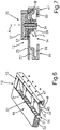
- FIG 3c is the one-piece rotating element 20 in a to Fig. 3a shown from different perspectives.
- an additional locking element 38 is provided.
- This locking element 38 is arranged on the element stem 34 and protrudes radially. It is an element spaced apart from the adjusting cam 36.
- a specific rotational position of the rotary element 20 can be locked with the locking element 38. In particular, this is the rotary position in which the flap 14 is arranged in the closed position.
- the ventilation device 12 has the already mentioned flap 14.
- This has a longitudinal axis C.
- the longitudinal axis C runs parallel to the axis of rotation B.
- the flap 14 has a triangular shape in a cross section perpendicular to its longitudinal axis C.
- the adjusting cam 36 represents an example of a coupling part with which the rotary element 20 is coupled directly to the flap 14.
- this coupling part in the form of the adjusting cam 36 engages the uneven underside of the flap 14, in particular the rear flank 40.
- the flap 14 is pivoted about the pivot axis B when the adjusting cam 36 slides along the rear flank 40.
- the flap 14 has a continuous recess 41. This is in particular designed as an open recess towards the rear end or towards the rear edge 24.
- the rotary element 20 with its element stem 34 can extend into this recess 41 or extend through it to the rear.
- the flat cylinder 37 or the flat cylinder-shaped upper partial element remains positioned above the flap 14.
- the element stem 34 can be seen in the context as an example of a coupling pin of the rotary element 20.
- the flat cylinder 37 is to be understood as an example of a flat cylinder-shaped rotating head of the rotating element 20.
- the ventilation device 12 also has lateral receptacles 42 and 43. These serve, on the one hand, as pivot bearings for the flap 14.
- pins 44 and 45 which are connected to the flap 14 in one piece, can be inserted into corresponding receptacles 46 for this purpose.
- these lateral receptacles 42, 43 also serve to fasten the rear rail or bar 16.
- a front rail or bar 47 of the ventilation device 12 can be fastened to it.
- plug connections are provided in this context. In this way, a rear insertion element 48 can be inserted into the groove 29 while holding it on the receptacles 42 and 43.
- a front insertion element 49 of the side receptacles 42, 43 can be inserted into a groove 50 of the one-piece front strip 47.
- Fig. 4 the ventilation device 12 is shown in the assembled state and with the flap 14 closed in a perspective sectional illustration. The cut is in Fig. 4 shown outside the rotating member 20. The flush arrangement of the upper side 25 with the remaining upper sides 26 can be seen.
- Fig. 5 the ventilation device 12 is shown in a vertical sectional view. The cut here is made by the rotary element 20.
- the flap 14 is shown here in the closed state or in the closed position. The cut is drawn through the recess 41 here.
- the base 33 is not shown here.
- An upper ventilation opening 51 facing away from the interior 13 ( Fig. 4 ) is closed by the flap 14.
- the ventilation opening 51 is part of the ventilation ducts 32.
- FIG. 12 is a perspective sectional view of the ventilation device 12 according to FIG Fig. 4 shown.
- the flap 14 is shown here in the open position. In this position, an air flow P can exit from the interior 13 of the food receptacle 8 via the ventilation ducts 32 and the upper ventilation opening 51 to the outside.
- FIG. 7 the ventilation device 12 with the flap 14 in the open position is shown in a sectional illustration, a section through the rotary element 20 and through the recess 41 being shown here.
- FIG. 8 is in one too Fig. 4
- the ventilation device 12 with the closed flap 14 is shown in a different perspective. However, a section through the rotary element 20 is shown here. It can be seen how the adjusting cam 36 is contacted directly on the uneven underside of the flap 14. In particular, in the closed position of the flap 14, the adjusting cam 36 is in contact with the V-tip 53 between the inclined front flank 39 and the inclined rear flank 40.
- Fig. 9 is in a for Fig. 6
- the ventilation device 12 is shown in different perspective views.
- the cut here is as in Fig. 8 .
- the open position of the flap 14 can be seen.
- the adjusting cam 36 is between the positions in FIG FIGS. 8 and 9 turned backwards. There is no longer any contact with the uneven underside.
- the adjusting cam 36 is positioned here in particular with its vertical leg in a stowage space 52.
- the base 33 is not shown.
- the flap 14 does not protrude beyond the upper side 26 in any of its possible positions.
- the ventilation channels 32 are through a further ventilation opening 54, see FIGS. 4 to 9 , limited.
- This ventilation opening 54 directed towards the interior 13 is delimited by the rails 16, 47 and the two lateral receptacles 42 and 43.
- Fig. 10 is shown in a corresponding representation in Fig. 2 a representation of the household refrigerator 1 is shown.
- the flap 14 has two separate sub-elements 55 and 56.
- the rotary element 20 is designed here as a roller 57.
- the other geometrical configurations are the same as in previous embodiments.
- Fig. 11 the embodiment of the ventilation device 12 is shown in an exploded view.
- the ventilation device 12 has, in particular, a rear strip 16. This can in particular be structurally identical to the bar in Fig. 3a be.
- a front bar 47 is provided. This can also be identical to the front bar 47 in Fig. 3a be.
- Lateral receptacles 42 and 43 of the ventilation device 12 in Fig. 11 can be identical to the side mounts 42 and 43 in Fig. 3a be.
- a base 33 is also provided here.
- This base 33 has a spring 58 here. This presses on flattened areas 59 and 60 of a jacket wall 61 of the roller 57. As a result, the rotating roller 57 can only move between two set positions. If the roller 57 is rotated forwards by a specific angle, for example between 50 ° and 70 °, in particular by 60 °, the position of the sub-elements 55 and 56 designed as wings can be adjusted individually.
- the axis of rotation A of the roller 57 is oriented horizontally here, in particular in the width direction of the food receptacle. In particular, the axis of rotation A is coaxial with the axis of rotation B of the flap 14.
- the two sub-elements 55 and 56 are arranged at opposite ends of the roller 57.
- a non-rotatable connection between the roller 57 and the sub-elements 55 and 56 is formed here.
- the sub-elements 55 and 56 are connected at the ends facing away from the roller 57 to the lateral receptacles 42 and 43, in particular rotatably mounted therein.
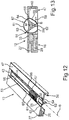
- Fig. 12 the ventilation device 12 is shown in a perspective sectional view.
- the flap 14 is arranged here in a closed position.
- the jacket wall 61 is structured.
- a non-slip structure This can be a configuration of grooves.
- a partial element is designed in its shape in cross section perpendicular to the axis of rotation B as a triangle. In particular, similar to one isosceles triangle.
- This sub-element 55 thus has three triangular points 62, 63 and 64.
- these triangular points 62 to 64 are formed with a radial distance from a center point M of this triangular shape, which is the same.
- the sub-element 56 is designed accordingly.
- a triangular tip 63 is arranged directly adjacent to a rear delimiting edge 65 of the ventilation opening 51.
- the triangular tip 64 is formed directly adjacent to a front boundary edge 66 of the ventilation opening 51.
- the third triangular tip 62 is arranged pointing downwards in this closed position.
- Fig. 13 In this context, a vertical sectional view through the ventilation device 12 in the area of the rotating roller 57 is shown.
- the flats 59, 60 of the jacket wall 61 are arranged here in such a way that the flat 59 is held in its position and the closed position of the sub-elements 55 and 56 is thereby reached. If, starting from this closed position of the flap 14, an open position is set, this is done by rotating the roller 57 about the axis of rotation B. This can take place with regard to the advantageously present flats 59 and 60 in the jacket wall 61 by a predetermined, defined angle. This can be according to the above-mentioned angular range.
- the sub-elements 55 and 56 are then rotated in such a way that the ventilation opening 51 is exposed.
- the triangular tip 63 is then positioned so as to protrude upward at a distance from the boundary edges 65 and 66. How to do this in the in Fig. 15 As shown in the vertical sectional view, this further flattened area 60 is then oriented downward and held by the spring 58.
- the extent of the sub-elements 55 and 56 is at a maximum, in particular equal, to the radius of the rotary roller 57, in particular in the area of the non-flattened areas of the jacket wall 61.
Abstract
Ein Aspekt der Erfindung betrifft einen Lebensmittel-Aufnahmebehälter (8) für ein Haushaltskältegerät (1), mit einer Schale (10) zur Aufnahme der Lebensmittel, mit einem dazu separaten Deckel (9), der zum Schließen der Schale (10) auf die Schale (10) aufsetzbar ist, und mit einer Lüftungsvorrichtung (12), mit welcher ein Luftaustausch zwischen der Umgebung und dem Inneren (13) des Lebensmittel-Aufnahmebehälters (8) durchführbar ist, wobei die Lüftungsvorrichtung (12) eine schwenkbare Klappe (14) aufweist, die in einer geöffneten Stellung eine Lüftungsöffnung (51) frei gibt und in der geschlossenen Stellung die Lüftungsöffnung (51) verschließt, wobei die Lüftungsvorrichtung (12) ein Betätigungselement zum Betätigen der Klappe (14) aufweist, wobei das Betätigungselement ein Drehelement (20) ist, welches um eine Drehachse (A) drehbar gelagert ist, wobei abhängig von der Drehbewegung des Drehelements (20) eine Schwenkbewegung der Klappe (14) erzeugt ist. Ein Aspekt betrifft auch ein Haushaltskältegerät (1).One aspect of the invention relates to a food storage container (8) for a household refrigeration appliance (1), with a bowl (10) for holding the food, with a separate lid (9) for closing the bowl (10) on the bowl (10) can be placed, and with a ventilation device (12) with which air can be exchanged between the environment and the interior (13) of the food receptacle (8), the ventilation device (12) having a pivotable flap (14). which releases a ventilation opening (51) in an open position and closes the ventilation opening (51) in the closed position, the ventilation device (12) having an actuating element for actuating the flap (14), the actuating element comprising a rotating element (20) which is rotatably mounted about an axis of rotation (A), a pivoting movement of the flap (14) being generated as a function of the rotary movement of the rotary element (20). One aspect also relates to a household refrigeration appliance (1).
Description
Ein Aspekt der Erfindung betrifft einen Lebensmittel-Aufnahmebehälter für ein Haushaltskältegerät. Der Lebensmittel-Aufnahmebehälter weist eine Schale zur Aufnahme der Lebensmittel auf. Der Lebensmittel-Aufnahmebehälter weist darüber hinaus einen zur Schale separaten Deckel auf, der zum Schließen der Schale auf die Schale aufsetzbar ist. Der Lebensmittel-Aufnahmebehälter weist eine Lüftungsvorrichtung auf, mit welcher ein Luftaustausch zwischen der Umgebung und dem Inneren des Lebensmittel-Aufnahmebehälters durchführbar ist. Die Lüftungsvorrichtung weist eine schwenkbare Klappe auf, die in einer geöffneten Stellung eine Lüftungsöffnung freigibt und in der geschlossenen Stellung die Lüftungsöffnung verschließt. Die Lüftungsvorrichtung weist eine schwenkbare Klappe auf. Ein weiterer Aspekt der Erfindung betrifft ein Haushaltskältegerät mit einem derartigen Lebensmittel-Aufnahmebehälter.One aspect of the invention relates to a food receptacle for a household refrigerator. The food receptacle has a tray for receiving the food. The food receptacle also has a lid which is separate from the shell and which can be placed on the shell to close the shell. The food receptacle has a ventilation device with which an exchange of air between the surroundings and the interior of the food receptacle can be carried out. The ventilation device has a pivotable flap which, in an open position, releases a ventilation opening and, in the closed position, closes the ventilation opening. The ventilation device has a pivotable flap. Another aspect of the invention relates to a household refrigerator with such a food receptacle.
Ein derartiges Haushaltskältegerät ist beispielsweise aus der
Es ist Aufgabe der vorliegenden Erfindung, einen Lebensmittel-Aufnahmebehälter für ein Haushaltskältegerät sowie ein derartiges Haushaltskältegerät zu schaffen, bei welchem die Klappe im Hinblick auf ihre Positionierung und Verstellung verbessert ausgebildet ist.It is the object of the present invention to provide a food receptacle for a household refrigeration appliance and such a household refrigeration appliance in which the flap is designed in an improved manner with regard to its positioning and adjustment.
Diese Aufgabe wird durch einen Lebensmittel-Aufnahmebehälter und ein Haushaltskältegerät gemäß den unabhängigen Ansprüchen gelöst.This object is achieved by a food receptacle and a household refrigerator according to the independent claims.
Ein Aspekt der Erfindung betrifft einen Lebensmittel-Aufnahmebehälter für ein Haushaltskältegerät. Der Lebensmittel-Aufnahmebehälter weist eine Schale zur Aufnahme von Lebensmitteln auf. Der Lebensmittel-Aufnahmebehälter weist darüber hinaus einen zur Schale separaten Deckel auf, der zum Schließen der Schale auf die Schale aufsetzbar ist. Der Lebensmittel-Aufnahmebehälter weist darüber hinaus eine Lüftungsvorrichtung auf, mit welcher ein Luftaustausch zwischen der Umgebung und einem Inneren des Lebensmittel-Aufnahmebehälters durchführbar ist. Die Lüftungsvorrichtung weist zumindest eine schwenkbare Klappe auf, die in einer geöffneten Stellung eine Lüftungsöffnung des Lebensmittel-Aufnahmebehälters freigibt und in der geschlossenen Stellung diese Lüftungsöffnung verschließt. Die Klappe weist eine Längsachse auf. Die Lüftungsvorrichtung weist ein Betätigungselement zum Betätigen der Klappe auf. Das Betätigungselement ist ein Drehelement, welches um eine Drehachse drehbar gelagert ist, wobei abhängig von der Drehbewegung des Drehelements eine Schwenkbewegung der Klappe erzeugt ist. Dadurch ist ein einfaches Bedienkonzept ermöglicht. Denn indem die Bewegungsart des Betätigungselements gleich der Bewegungsart der Klappe ist, ist ein intuitives und nutzerfreundliches, da auch leicht nachvollziehbares Bedienkonzept erreicht. Des Weiteren verbleibt ein Drehelement als Ganzes betrachtet bei seiner Betätigung in seiner Position an dem Lebensmittel-Aufnahmebehälter unverändert, sodass im Vergleich zu einem Schieber wenig Platz benötigt wird.One aspect of the invention relates to a food receptacle for a household refrigerator. The food receptacle has a tray for receiving food. The food receptacle also has a lid which is separate from the shell and which can be placed on the shell to close the shell. The food receptacle also has a ventilation device with which an exchange of air between the surroundings and an interior of the food receptacle can be carried out. The ventilation device has at least one pivotable flap which, in an open position, releases a ventilation opening of the food receptacle and closes this ventilation opening in the closed position. The flap has a longitudinal axis. The ventilation device has an actuating element for actuating the flap. The actuating element is a rotary element which is mounted rotatably about an axis of rotation, a pivoting movement of the flap being generated as a function of the rotary movement of the rotary element. This enables a simple operating concept. Because the type of movement of the actuating element is the same as the type of movement of the flap, an intuitive and user-friendly, as it is also easy to understand, operating concept is achieved. Furthermore, viewed as a whole, a rotary element remains unchanged in its position on the food receptacle when it is actuated, so that little space is required compared to a slide.
Vorzugsweise ist vorgesehen, dass die Lüftungsvorrichtung eine Koppelschiene aufweist. Die Koppelschiene weist eine in Tiefenrichtung betrachtet nach hinten offene Nut auf. Im montierten Zustand der Lüftungsvorrichtung an dem Deckel greift der Vorderrand des Deckels in diese Nut ein. Der vordere Rand ist somit darin eingeführt und gehalten. Eine derartige mechanische Verbindung ist sehr stabil und dauerhaft haltend. Die Lüftungsvorrichtung kann somit auch lagegenau mit dem Deckel verbunden werden. Durch die Lüftungsvorrichtung und den Deckel ist ein gesamtes Deckelmodul gebildet. Mit diesem kann eine Beschickungsöffnung der Schale von oben abgedeckt werden.It is preferably provided that the ventilation device has a coupling rail. The coupling rail has a groove that is open to the rear, viewed in the depth direction. When the ventilation device is installed on the cover, the front edge of the cover engages in this groove. The leading edge is thus inserted and held therein. Such a mechanical connection is very stable and durable. The The ventilation device can thus also be connected to the cover in a precisely positioned manner. An entire cover module is formed by the ventilation device and the cover. This can be used to cover a loading opening of the tray from above.
Vorzugsweise ist vorgesehen, dass das Drehelement einen Flachzylinder als greifbares Betätigungselement aufweist. Der Flachzylinder kann so orientiert sein, dass er mit seiner Längsachse vertikal orientiert ist. Insbesondere ist die Drehachse des Drehelements in Höhenrichtung orientiert. Insbesondere ist die Drehachse gleich der Längsachse. Durch diese Ausgestaltung wird eine Höhenrichtung flachbauendes Betätigungselement realisiert. Es steht somit nur minimal nach oben über insbesondere mit dem Flachzylinder. Es ist jedoch exponiert angeordnet und kann somit von einem Nutzer leicht gegriffen und gedreht werden. Diesbezüglich ist auch eine ergonomische und einfache Drehbewegung ermöglicht. Insbesondere ist das Drehelement mit seiner Mantelwand des Flachzylinders exponiert nach oben hin freiliegend, sodass die Mantelwand des Drehelements umfangsseitig vollständig gegriffen werden kann.It is preferably provided that the rotary element has a flat cylinder as a grippable actuating element. The flat cylinder can be oriented such that it is oriented vertically with its longitudinal axis. In particular, the axis of rotation of the rotary element is oriented in the height direction. In particular, the axis of rotation is the same as the longitudinal axis. By means of this configuration, an actuating element which is flat in height is realized. It thus projects only minimally upwards, in particular with the flat cylinder. However, it is arranged in an exposed manner and can therefore be easily grasped and rotated by a user. In this regard, an ergonomic and simple rotary movement is also made possible. In particular, the casing wall of the flat cylinder of the rotating element is exposed at the top, so that the casing wall of the rotating element can be fully gripped on the circumference.
Vorzugsweise ist die Klappe brettartig ausgebildet. Sie weist insbesondere eine unebene Unterseite auf. Im Querschnitt senkrecht zur Längsachse der Klappe ist diese Unebenheit durch eine in Tiefenrichtung betrachtet nach vorne und nach oben schräg orientierte Vorderflanke und eine nach hinten und nach oben schräg orientierte Hinterflanke ausgebildet. Insbesondere ist die Querschnittgeometrie der Klappe als flache Dreieickform gebildet. Der Basisschenkel dieser Dreieckform ist die in Höhenrichtung betrachtet obere Seite. Die beiden oben genannten schräg orientierten Flanken münden am in Höhenrichtung tiefsten Punkt aneinander an. Durch eine derartige Ausgestaltung ist die Stabilität der Klappe erhöht. Die Verwindungssteifigkeit ist erhöht.The flap is preferably designed like a board. In particular, it has an uneven underside. In the cross-section perpendicular to the longitudinal axis of the flap, this unevenness is formed by a front flank which is oriented obliquely forwards and upwards when viewed in the depth direction and a rear flank which is oriented obliquely towards the rear and upwards. In particular, the cross-sectional geometry of the flap is designed as a flat triangular shape. The base leg of this triangular shape is the upper side viewed in the vertical direction. The two above-mentioned obliquely oriented flanks merge at the lowest point in the height direction. Such a configuration increases the stability of the flap. The torsional stiffness is increased.
Vorzugsweise ist vorgesehen, dass das Drehelement ein Koppelteil aufweist. Bei der Drehbewegung des Drehelements ist die Vorderflanke der oben genannten spezifisch geformten Klappe durch das Koppelteil kontaktiert. Eine Relativbewegung zwischen dem Koppelteil und der Vorderflanke resultiert. Ein Entlanggleiten des Koppelteils an der Vorderflanke bei dieser Drehbewegung ist einhergehend. Dies erfolgt derart, dass die Klappe dadurch um ihre Schwenkachse zur Einstellung der geöffneten Stellung oder der geschlossenen Stellung verschwenkbar ist. Insbesondere ist diese Schwenkachse in Breitenrichtung des Lebensmittel-Aufnahmebehälters orientiert. Durch diese Ausgestaltung wird ein einfaches Konzept realisiert, welches die Umsetzung der Drehbewegung des Drehelements in eine Drehbewegung bzw. Schwenkbewegung der Klappe ermöglicht. Dadurch ist auch ein klemmfreies sowie leichtgängiges kontinuierliches Verstellen der Stellung der Klappe möglich. Ein sehr nutzerfreundliches Bedienkonzept ist dadurch erreicht.It is preferably provided that the rotary element has a coupling part. During the rotary movement of the rotary element, the front flank of the above-mentioned specifically shaped flap is contacted by the coupling part. A relative movement between the coupling part and the leading edge results. The coupling part slides along the front flank during this rotary movement. This is done in such a way that the flap can thereby be pivoted about its pivot axis for setting the open position or the closed position. In particular, this pivot axis is oriented in the width direction of the food receptacle. Through this Embodiment, a simple concept is implemented which enables the conversion of the rotary movement of the rotary element into a rotary movement or pivoting movement of the flap. This also enables the position of the flap to be continuously adjusted without jamming and smoothly. This results in a very user-friendly operating concept.
Vorzugsweise ist vorgesehen, dass die Klappe in der geschlossenen Stellung horizontal orientiert ist. In der geöffneten Stellung der Klappe ist sie im Vergleich dazu in Höhenrichtung betrachtet nach unten geschwenkt. Durch eine derartige Ausgestaltung ist ein unerwünschtes nach oben überstehen der Klappe sowohl in der geöffneten Stellung als auch in der geschlossenen Stellung vermieden. Nach oben überstehende Kanten oder Ecken der Klappe können dadurch vermieden werden.It is preferably provided that the flap is oriented horizontally in the closed position. In the open position of the flap, it is pivoted downwards in comparison to this, viewed in the vertical direction. Such a configuration prevents the flap from protruding upwards, both in the open position and in the closed position. Edges or corners of the flap protruding upwards can thus be avoided.
Vorzugsweise ist vorgesehen, dass die Schwenkachse beziehungsweise die Drehachse an einem in Tiefenrichtung vorderen Ende der Klappe ausgebildet ist. Eine derartige endseitige Ausgestaltung ermöglicht es auch, dass dieses Ende der Klappe in allen Stellungen quasi auf gleicher Höhenlage angeordnet ist. Auch dadurch ist der oben genannte Vorteil, dass in allen Stellungen ein unerwünschtes nach oben Überstehen der Klappe vermieden ist, unterstützt.It is preferably provided that the pivot axis or the axis of rotation is formed on a front end of the flap in the depth direction. Such an end configuration also makes it possible that this end of the flap is arranged in all positions, so to speak, at the same height. This also supports the above-mentioned advantage that an undesired upward protrusion of the flap is avoided in all positions.
Vorzugsweise ist vorgesehen, dass die Lüftungsvorrichtung zumindest ein Lüftungsgitter aufweist. Dieses Lüftungsgitter weist mehrere, nebeneinander ausgebildete Lüftungskanäle auf. Durch eine derartige Ausgestaltung wird nicht ein Lüftungskanal, der sich über die gesamte Breite der Schale erstreckt gebildet, sondern diesbezüglich mehrere in dieser Breitenrichtung nebeneinander ausgebildete Lüftungskanäle gebildet. Dadurch ist das Bauteil, in welchem diese Lüftungskanäle ausgebildet sind, im Vergleich zu lediglich einem einzigen Lüftungskanal auch stabiler und verwindungssteifer gebildet. Die Trennwände, die die Lüftungskanäle voneinander separieren können somit auch als Stabilisierungsstege genutzt werden.It is preferably provided that the ventilation device has at least one ventilation grille. This ventilation grille has several ventilation channels formed next to one another. Such a configuration does not form a ventilation duct that extends over the entire width of the shell, but rather a plurality of ventilation ducts formed next to one another in this width direction in this regard. As a result, the component in which these ventilation ducts are formed is also made more stable and torsion-resistant compared to just a single ventilation duct. The partition walls that separate the ventilation ducts from one another can therefore also be used as stabilizing bars.
Vorzugsweise ist vorgesehen, dass das Drehelement in einem weiteren Ausführungsbeispiel als Walze ausgebildet ist. Bei einer derartigen Ausgestaltung ist das Drehelement somit nicht als Flachzylinder, sondern als Hochzylinder gebildet. Dies bedeutet, dass in Richtung seiner Längsachse betrachtet die Höhe größer ist, als ein radiales Ausmaß dieses Zylinders. Bei dem Flachzylinder ist dies genau umgekehrt der Fall. Durch eine derartige Ausgestaltung als Walze können diesbezüglich unterschiedliche Einbaukonzepte und Orientierungen des Drehelements genutzt werden. Dadurch kann situationsabhängig ein verbesserter Verbau, der platzsparend realisiert ist, ermöglicht werden. Dennoch ist auch hier die Bedienfreundlichkeit hoch.It is preferably provided that the rotary element is designed as a roller in a further exemplary embodiment. In such a configuration, the rotary element is thus not formed as a flat cylinder, but as a high cylinder. This means that, viewed in the direction of its longitudinal axis, the height is greater than a radial extent of this cylinder. In the case of the flat cylinder, this is exactly the opposite. With such a configuration as a roller, different installation concepts and orientations of the rotary element can be used in this regard. As a result, depending on the situation, an improved shoring that is implemented in a space-saving manner can be made possible. Nevertheless, the user-friendliness is also high here.
Es kann vorgesehen sein, dass die Drehachse dieses Drehelements in Breitenrichtung des Lebensmittel-Aufnahmebehälters orientiert ist. Das Drehelement ist somit bezüglich seiner Längsachse nicht aufgestellt, sondern liegend angeordnet. Dadurch ist es in besonders vorteilhafter Weise ermöglicht, dass die Betätigung des Drehelements über seine Mantelwand erfolgen kann. Eine großflächige Berührung dieser Mantelwand ist dadurch erreicht. Auch dadurch ist ein nutzerfreundliches Konzept ermöglicht.It can be provided that the axis of rotation of this rotary element is oriented in the width direction of the food receptacle. The rotary element is therefore not set up with respect to its longitudinal axis, but rather is arranged horizontally. This makes it possible in a particularly advantageous manner that the rotary element can be actuated via its jacket wall. A large area of contact with this jacket wall is achieved. This also enables a user-friendly concept.
Insbesondere ist es bei einer derartigen Ausgestaltung eines Drehelements als Walze, welche liegend positioniert ist, auch ermöglicht, diese relativ versenkt in dem Lebensmittel-Aufnahmebehälter zu verbauen. Dadurch ragt sie wenig nach oben über. Dennoch ist die Mantelwand der Walze einfach und umfänglich berührbar und betätigbar.In particular, with such a configuration of a rotary element as a roller, which is positioned horizontally, it is also possible to install this relatively sunk in the food receptacle. As a result, it protrudes little above. Nevertheless, the jacket wall of the roller can be easily and extensively touched and actuated.
In einer vorteilhaften Ausführung ist vorgesehen, dass die Walze an einem Ende mit einem ersten Teilelement der Klappe verbunden ist. Insbesondere kann hier eine direkte Verbindung vorgesehen sein. Durch eine derartige Ausgestaltung wird somit ein minimalistisches Prinzip im Hinblick auf die Kopplung zwischen dem Drehelement und der Klappe ermöglicht. Es werden keine verbindenden, zusätzlichen separaten Zwischenteile benötigt. In einer vorteilhaften Ausführung ist vorgesehen, dass an dem gegenüberliegenden Ende der Walze ein zweites Teilelement der Klappe angeordnet ist beziehungsweise direkt damit verbunden ist. Damit wird eine Gesamtschiene aus den beiden Teilelementen mit der dazwischenliegenden Walze gebildet. Diese Gesamtschiene ist dann entsprechend drehbar, insbesondere um die Drehachse. Durch diesen insbesondere symmetrischen Aufbau der Gesamtschiene ist auch eine einfache Bedienung ermöglicht. Die zu erzeugende Drehbewegung ist auch in dieser Ausführung leicht gängig ermöglicht. Teilelemente, die somit beidseits der Walze als Flügel abstehen können einfach in die Drehbewegung versetzt werden. Die Teilelemente und die Walze sind somit in Breitenrichtung in Reihe zueinander angeordnet. Insbesondere ist dadurch auch ein bauteilminimiertes Konzept ermöglicht, welches sehr platzsparend verbaut werden kann. Dennoch ist das Wirkprinzip zur Erzeugung der Schwenkbewegung der Klappe einfach und präzise. Insbesondere ist die Walze mit den Teilelementen direkt und drehfest verbunden.In an advantageous embodiment it is provided that the roller is connected at one end to a first sub-element of the flap. In particular, a direct connection can be provided here. Such a configuration thus enables a minimalist principle with regard to the coupling between the rotary element and the flap. No connecting, additional, separate intermediate parts are required. In an advantageous embodiment it is provided that a second partial element of the flap is arranged at the opposite end of the roller or is directly connected to it. In this way, an overall rail is formed from the two sub-elements with the roller in between. This overall rail can then be correspondingly rotated, in particular about the axis of rotation. This particularly symmetrical structure of the overall rail also enables simple operation. The rotary movement to be generated is also easily made possible in this embodiment. Partial elements, which thus protrude as wings on both sides of the roller, can simply be set in rotation. The sub-elements and the roller are thus arranged in a row with one another in the width direction. In particular, this also enables a component-minimized concept that is installed in a very space-saving manner can be. Nevertheless, the operating principle for generating the pivoting movement of the flap is simple and precise. In particular, the roller is directly and non-rotatably connected to the sub-elements.
Vorzugsweise ist vorgesehen, dass die Klappe in einem Querschnitt senkrecht zu ihrer Längsachse betrachtet eine Dreieckform bildet beziehungsweise ein Dreieck ist. Insbesondere trifft dies auf beide Teilelemente der Klappe zu. Insbesondere ist dieser Querschnitt als Dreieck mit gleichen radialen Abständen der Dreieckspitzen zum Mittelpunkt dieser Dreieckform ausgebildet. Dieser Mittelpunkt ist insbesondere auch durch die Längsachse eines Teilelements gebildet. Durch eine derartige Ausgestaltung wird quasi eine symmetrische Dreieckform gebildet. Damit kann das Einstellen der geöffneten Stellung und der geschlossenen Stellung vorteilhaft erfolgen. Denn es ist hier nur eine einfache Drehbewegung erforderlich und der Lüftungskanal kann mit einer einfachen Geometrie gestaltet werden. Im geschlossenen Zustand der Klappe ist die Orientierung dieses Dreiecks derart, dass eine Dreieckspitze unmittelbar an einem vorderen Begrenzungsrand der Lüftungsöffnung anliegt beziehungsweise benachbart dazu positioniert ist und ein in Umlaufrichtung der Längsachse folgende zweite Dreiecksspitze benachbart zur hinteren Begrenzung dieser Lüftungsöffnung des Lüftungskanals angeordnet ist. Demgegenüber ist in einer geöffneten Stellung der Klappe diese Dreieckform so orientiert, dass eine Dreieckspitze nach oben zeigend orientiert ist und in Tiefenrichtung betrachtet im Abstand sowohl zum vorderen Begrenzungsrand als auch zum hinteren Begrenzungsrand dieser Lüftungsöffnung angeordnet ist. Ein Durchströmen von Luft durch den Lüftungskanal, insbesondere vom Inneren des Lebensmittel-Aufnahmebehälters nach außen ist dadurch einfach möglich.It is preferably provided that the flap, viewed perpendicular to its longitudinal axis, forms a triangular shape or is a triangle in a cross section. In particular, this applies to both sub-elements of the flap. In particular, this cross-section is designed as a triangle with the same radial distances between the triangle tips and the center of this triangular shape. This center point is in particular also formed by the longitudinal axis of a sub-element. Such a configuration creates a quasi symmetrical triangular shape. The setting of the open position and the closed position can thus be carried out advantageously. Because only a simple rotary movement is required here and the ventilation duct can be designed with a simple geometry. In the closed state of the flap, the orientation of this triangle is such that a triangle point lies directly against a front boundary edge of the ventilation opening or is positioned adjacent to it and a second triangle point following in the circumferential direction of the longitudinal axis is arranged adjacent to the rear boundary of this ventilation opening of the ventilation duct. In contrast, in an open position of the flap, this triangular shape is oriented so that a triangular tip is oriented upwards and, viewed in the depth direction, is arranged at a distance from both the front boundary edge and the rear boundary edge of this ventilation opening. A flow of air through the ventilation duct, in particular from the inside of the food receptacle to the outside, is thereby easily possible.
Es kann vorgesehen sein, dass die Kanten dieses Dreiecks geradlinige Verbindungslinien zwischen den Dreiecksspitzen sind. Insbesondere ist dann ein gleichschenkliges Dreieck ausgebildet. Es kann auch vorgesehen sein, dass die Verbindungslinien zwischen den Dreieckspitzen gekrümmte Linien sind. Diese können insbesondere konkav gekrümmt sein. Insbesondere kann auch hier eine gleiche Ausgestaltung dieser gekrümmten Verbindungslinien gebildet sein.It can be provided that the edges of this triangle are straight connecting lines between the triangle tips. In particular, an isosceles triangle is then formed. It can also be provided that the connecting lines between the triangle tips are curved lines. These can in particular be curved in a concave manner. In particular, the same configuration of these curved connecting lines can also be formed here.
In einer vorteilhaften Ausgestaltung ist vorgesehen, dass der Radius der Walze gleich dem radialen Abstand einer Dreiecksspitze zum genannten Mittelpunkt ist. Dies ist eine weitere sehr vorteilhafte Ausführung. Denn dadurch ist verhindert, dass eine Dreiecksspitze in radialer Richtung über die Mantelwand der Walze nach außen übersteht. Dies wäre dann nachteilig, wenn die Walze im Bereich einer Lüftungsöffnung des Lüftungskanals ist. Denn dann könnte im Bereich dieser Walze nur ein bedingtes Schließen dieser Lüftungsöffnung erreicht werden. Durch die oben genannte vorteilhafte geometrische Ausgestaltung dient die Walze dann auch zusätzlich zu diesen Teilelementen als Verschlussteil der Klappe. Sie stellt dann auch quasi ein Bestandteil der Klappe im Hinblick auf ihre abdeckende Funktion der Lüftungsöffnung dar.In an advantageous embodiment, it is provided that the radius of the roller is equal to the radial distance between a triangle tip and the center mentioned. this is a another very advantageous embodiment. This is because this prevents a triangular tip from protruding outward in the radial direction beyond the jacket wall of the roller. This would be disadvantageous if the roller is in the area of a ventilation opening of the ventilation duct. Because then only a limited closing of this ventilation opening could be achieved in the area of this roller. Due to the above-mentioned advantageous geometric configuration, the roller then also serves as a closure part of the flap in addition to these sub-elements. It then also represents a part of the flap with regard to its covering function of the ventilation opening.
In einer vorteilhaften Ausführung ist vorgesehen, dass die Mantelwand der Walze strukturiert ist. Diesbezüglich kann eine Strukturierung vorgesehen sein, die abrutschreduzierend ausgebildet ist. Insbesondere ist diese Mantelwand somit keine glatte Oberfläche. Die Strukturierung kann eine Ausgestaltung mit Rillen oder einem sonstigen Muster sein. Dadurch kann beim Anliegen eines Fingers auf diese Mantelwand ein Abrutschen des Fingers vermieden werden. Ein zuverlässiges und sicheres Drehen der Walze ist dadurch ermöglicht.In an advantageous embodiment it is provided that the jacket wall of the roller is structured. In this regard, structuring can be provided which is designed to reduce slip. In particular, this jacket wall is therefore not a smooth surface. The structuring can be an embodiment with grooves or some other pattern. As a result, when a finger is in contact with this jacket wall, the finger can be prevented from slipping. A reliable and safe rotation of the roller is thereby made possible.
Insbesondere ist die Längsachse der Walze koaxial zur Längsachse der Teilelemente. Insbesondere sind diese Längsachsen koaxial zur Schwenkachse der Klappe.In particular, the longitudinal axis of the roller is coaxial with the longitudinal axis of the sub-elements. In particular, these longitudinal axes are coaxial with the pivot axis of the flap.
Insbesondere ist bei den oben genannten Konzepten vorgesehen, dass die Lüftungsvorrichtung seitliche Aufnahmen aufweisen, an denen die Klappe jeweils drehbar gelagert ist. An diesen seitlichen Aufnahmen kann ein frontseitiges Profil bzw. eine frontseitige Schiene der Lüftungsvorrichtung angeordnet sein. Insbesondere ist dieses frontseitige Profil also im Querschnitt U-artige Schiene gestaltet. Sie kann als zu den Aufnahmen separate Komponente ausgebildet sein. Sie kann in dem Zusammenhang durch eine Steckverbindung jeweils mit einer derartigen seitlichen Aufnahme verbunden sein. Vorzugsweise weist die Lüftungsvorrichtung eine hintere Schiene auf. Diese ist separat zur vorderen Schiene ausgebildet. Zwischen der vorderen Schiene und der hinteren Schiene ist die Klappe und das Drehelement angeordnet. Die hintere Schiene kann vorzugsweise eine nach hinten offene Nut aufweisen. In diese Nut ist dieser vordere Rand des Deckels eingeführt und darin gehalten. Insbesondere ist dieses hintere Profil beziehungsweise die hintere Schiene zerstörungsfrei lösbar mit den seitlichen Aufnahmen verbunden. Auch hier kann entsprechend wie bei der vorderen Schiene beziehungsweise dem vorderen Profil eine Steckverbindung vorgesehen sein. Bei beiden Ausgestaltungen können diese beiden Profile und die seitlichen Aufnahmen vorgesehen sein.In particular, it is provided in the above-mentioned concepts that the ventilation device have lateral receptacles on which the flap is rotatably mounted in each case. A front-side profile or a front-side rail of the ventilation device can be arranged on these lateral receptacles. In particular, this front profile is thus designed with a U-shaped rail in cross section. You can be designed as a separate component to the recordings. In this context, it can be connected to such a lateral receptacle by a plug connection. The ventilation device preferably has a rear rail. This is designed separately from the front rail. The flap and the rotating element are arranged between the front rail and the rear rail. The rear rail can preferably have a groove that is open towards the rear. This front edge of the cover is inserted into this groove and held therein. In particular, this rear profile or the rear rail is non-destructively detachable connected to the lateral receptacles. Again, as with the front rail, respectively the front profile can be provided with a plug connection. In both configurations, these two profiles and the lateral receptacles can be provided.
Es kann vorgesehen sein, dass die Lüftungsvorrichtung an einem vorderen Rand des Deckels angeordnet ist und gegenüber dem vorderen Rand nach vorne ragend angeordnet ist. In Tiefenrichtung betrachtet ist die Lüftungsvorrichtung in einem Freiraum, der zwischen dem vorderen Rand des Deckels und einem oberen Schalenflansch der Schale ausgebildet ist, angeordnet. Bei einer derartigen Ausgestaltung ist in vorteilhafter Weise diese Lüftungsvorrichtung als Gesamtmodul quasi von vorne auf den Deckel aufgebracht, beispielsweise aufgesteckt.It can be provided that the ventilation device is arranged on a front edge of the cover and is arranged so as to protrude forwards with respect to the front edge. Viewed in the depth direction, the ventilation device is arranged in a free space which is formed between the front edge of the cover and an upper shell flange of the shell. In such a configuration, this ventilation device is advantageously applied to the cover as an overall module from the front, for example pushed on.
Vorzugsweise ist vorgesehen, dass in Tiefenrichtung des Lebensmittel-Aufnahmebehälters betrachtet die Klappe vollständig vor einem vorderen Rand des Deckels und berührungslos zum vorderen Rand angeordnet ist. Durch diese Ausgestaltung ist es ermöglicht, dass der Deckel selbst als einheitliche und unterbrechungsfreie Platte ausgebildet werden kann. Dadurch ist die Herstellung einfacher. Indem die Klappe somit quasi außerhalb der Flächenmaße des Deckels angeordnet ist und spezifisch in Tiefenrichtung sogar vor dem Deckel positioniert ist, kann die Bewegbarkeit der Klappe, insbesondere bezüglich einer entsprechenden Mechanik, einfacher und bedarfsgerechter erfolgen. Es ist in dem Zusammenhang somit eine Lüftungsöffnung nicht mehr in den Deckel selbst integral ausgebildet, sondern eine Lüftungsöffnung zwischen einem Deckel, insbesondere einem vorderen Rand des Deckels, und der Schale, insbesondere einem oberen Frontflansch bzw. Schalenflansch einer Frontwand, gebildet.It is preferably provided that, viewed in the depth direction of the food receptacle, the flap is arranged completely in front of a front edge of the lid and without contact to the front edge. This configuration makes it possible for the cover itself to be designed as a uniform and uninterrupted plate. This makes production easier. Since the flap is thus arranged more or less outside the surface dimensions of the cover and is specifically positioned in the depth direction even in front of the cover, the flap can be moved more easily and in a more needs-based manner, in particular with regard to a corresponding mechanism. In this context, a ventilation opening is no longer integrally formed in the cover itself, but a ventilation opening is formed between a cover, in particular a front edge of the cover, and the shell, in particular an upper front flange or shell flange of a front wall.
Vorzugsweise ist vorgesehen, dass die Lüftungsvorrichtung ein zur Klappe separates Betätigungselement aufweist, durch dessen Betätigung die Klappe schwenkbar ist. Durch diese Ausgestaltung lässt sich eine einfache und nutzerfreundliche Betätigung der Klappe erreichen. Durch eine nach oben freiliegende und einfach zugängliche Ausgestaltung des Betätigungselements kann ein Nutzer dieses auch einfach greifen und entsprechend betätigen.It is preferably provided that the ventilation device has an actuating element which is separate from the flap and which can be actuated to pivot the flap. This configuration enables simple and user-friendly actuation of the flap to be achieved. As a result of an easily accessible design of the actuating element that is exposed at the top, a user can also easily grip it and actuate it accordingly.
In einer vorteilhaften Ausführung kann vorgesehen sein, dass die Lüftungsvorrichtung als eigenes Modul ausgebildet ist, welches dann auch ein Nachrüstmodul sein kann. Dies bedeutet, dass auch eine Ausgestaltung eines Lebensmittel-Aufnahmebehälters, der zunächst nur mit der Schale und einem spezifischen Deckel ausgebildet ist, mit einer derartigen Lüftungsvorrichtung nachträglich nachgerüstet werden kann. Dies ist insbesondere bei dieser Ausgestaltung von Vorteil, bei welcher eine Klappe nicht in einer im Deckel ausgebildeten Aussparung eingesetzt werden muss, sondern bei welcher der Deckel für sich betrachtet als ebene, unterbrechungsfreie Platte ausgebildet ist. Durch in dem Zusammenhang dann relativ einfaches frontseitiges Anbringen des Moduls an den Deckel ist dann auch das Nachrüsten relativ einfach möglich.In an advantageous embodiment it can be provided that the ventilation device is designed as a separate module, which can then also be a retrofit module. This means that an embodiment of a food receptacle, which is initially only designed with the shell and a specific lid, can also be retrofitted with such a ventilation device. This is particularly advantageous in this embodiment, in which a flap does not have to be inserted in a recess formed in the cover, but in which the cover, viewed in isolation, is designed as a flat, uninterrupted plate. Retrofitting is then also relatively easy due to the relatively simple front-side attachment of the module to the cover.
In einer vorteilhaften Ausführung ist vorgesehen, dass der Lebensmittel-Aufnahmebehälter eine Anzeigeleiste aufweist, mit welcher eine geöffnete Stellung und eine geschlossene Stellung der Klappe symbolisch angezeigt sind. Diese Anzeigeleiste kann ein separates Bauteil sein. Die Anzeigeleiste kann zumindest bereichsweise unter dem Deckel angeordnet sein und sich somit unter dem Deckel erstrecken. Die Anzeigeleiste ist bei Betrachtung des Lebensmittel-Aufnahmebehälters von oben benachbart zu dem Betätigungselement angeordnet. Dadurch kann eine örtlich unmittelbare Zuordnung der Stellung des Betätigungselements zu der Anzeigeleiste erfolgen, sodass dann in verbesserter Art und Weise eindeutig erkannt wird, welche Stellung das Betätigungselement und somit dann auch die Klappe aufweist.In an advantageous embodiment, it is provided that the food receptacle has a display strip with which an open position and a closed position of the flap are symbolically displayed. This display bar can be a separate component. The display bar can be arranged at least in some areas under the cover and thus extend under the cover. When the food receptacle is viewed from above, the display bar is arranged adjacent to the actuating element. As a result, the position of the actuating element can be directly assigned to the display strip locally, so that it is then clearly recognized in an improved manner which position the actuating element and thus also the flap have.
Die Anzeigeleiste kann in vorteilhafter Weise zerstörungsfrei lösbar an dem Deckel und/oder an einem Trägerelement der Lüftungsvorrichtung angeordnet sein. Dadurch ist es auch ermöglicht, die Anzeigeleiste auszutauschen.The display bar can advantageously be arranged on the cover and / or on a carrier element of the ventilation device so as to be non-destructive and detachable. This also makes it possible to exchange the display bar.
Ein weiterer Aspekt der Erfindung betrifft ein Haushaltskältegerät mit zumindest einem Lebensmittel-Aufnahmebehälter gemäß dem oben genannten Aspekt oder einer vorteilhaften Ausgestaltung davon. Das Haushaltskältegerät kann ein Kühlgerät oder ein Gefriergerät oder ein Kühl-Gefrier-Kombigerät sein. Das Haushaltskältegerät weist ein Gehäuse auf, in dem zumindest ein Aufnahmeraum für Lebensmittel ausgebildet ist. Der Lebensmittel-Aufnahmebehälter kann in dem Aufnahmeraum angeordnet sein und bildet, insbesondere im geschlossenen Zustand des Deckels auf der Schale, einen eigenen abgeschlossenen Lagerbereich. Der Lebensmittel-Aufnahmebehälter kann insbesondere ein Frischhaltebehälter sein, in dem eine individuelle Lagerbedingung, insbesondere eine individuelle Temperatur und/oder Luftfeuchte, eingestellt werden kann.Another aspect of the invention relates to a household refrigerator with at least one food receptacle according to the above aspect or an advantageous embodiment thereof. The household refrigerator can be a refrigerator or a freezer or a combined refrigerator-freezer. The household refrigerator has a housing in which at least one receiving space for food is formed. The food receptacle can be arranged in the receptacle and forms, in particular when the lid is closed on the tray, its own closed storage area. The food receptacle can in particular be a fresh food container in which an individual storage condition, in particular an individual temperature and / or humidity, can be set.
Damit ist es ermöglicht, eine zu dem restlichen Bereich des Aufnahmeraums unterschiedliche Lagerbedingung einzustellen. Dies ist insbesondere vorteilhaft zur Lagerung von spezifischen Lebensmitteln wie beispielsweise Obst oder Gemüse oder Fleisch, wie beispielsweise Fisch.This makes it possible to set a storage condition that differs from the rest of the area of the receiving space. This is particularly advantageous for storing specific foods such as fruit or vegetables or meat such as fish.
Es kann vorgesehen sein, dass das Haushaltskältegerät eine Befeuchtungseinrichtung aufweist, mit welcher die individuelle Luftfeuchte in dem Lebensmittel-Aufnahmebehälter einstellbar ist.It can be provided that the household refrigerator has a humidifying device with which the individual air humidity in the food receptacle can be adjusted.
Vorzugsweise ist der Lebensmittel-Aufnahmebehälter aus dem Aufnahmeraum entnehmbar und wieder einsetzbar und somit auch ein tragbarer beziehungsweise mobiler Behälter.The food receptacle can preferably be removed from the receptacle and reinserted and thus also a portable or mobile container.
Mit den Angaben "oben", "unten", "vorne", "hinten, "horizontal", "vertikal", "Tiefenrichtung", "Breitenrichtung", "Höhenrichtung" sind die bei bestimmungsgemäßen Gebrauch und bestimmungsgemäßen Anordnen des Behälters beziehungsweise des Geräts gegebenen Positionen und Orientierungen angegeben.The terms "top", "bottom", "front", "rear", "horizontal", "vertical", "depth direction", "width direction", "height direction" mean that the container or the device is used and arranged as intended given positions and orientations.
Weitere Merkmale der Erfindung ergeben sich aus den Ansprüchen, den Figuren und der Figurenbeschreibung. Die vorstehend in der Beschreibung genannten Merkmale und Merkmalskombinationen, sowie die nachfolgend in der Figurenbeschreibung genannten und/oder in den Figuren alleine gezeigten Merkmale und Merkmalskombinationen sind nicht nur in der jeweils angegebenen Kombination, sondern auch in anderen Kombinationen oder in Alleinstellung verwendbar, ohne den Rahmen der Erfindung zu verlassen. Es sind somit auch Ausführungen von der Erfindung als umfasst und offenbart anzusehen, die in den Figuren nicht explizit gezeigt und erläutert sind, jedoch durch separierte Merkmalskombinationen aus den erläuterten Ausführungen hervorgehen und erzeugbar sind. Es sind auch Ausführungen und Merkmalskombinationen als offenbart anzusehen, die somit nicht alle Merkmale eines ursprünglich formulierten unabhängigen Anspruchs aufweisen.Further features of the invention emerge from the claims, the figures and the description of the figures. The features and combinations of features mentioned above in the description, as well as the features and combinations of features mentioned below in the description of the figures and / or shown alone in the figures, can be used not only in the specified combination, but also in other combinations or on their own, without the frame to leave the invention. There are thus also embodiments of the invention to be regarded as encompassed and disclosed, which are not explicitly shown and explained in the figures, but emerge and can be generated from the explained embodiments by means of separate combinations of features. Designs and combinations of features are also to be regarded as disclosed, which therefore do not have all the features of an originally formulated independent claim.
Ausführungsbeispiele der Erfindung werden nachfolgend anhand schematischer Zeichnungen näher erläutert. Es zeigen:
- Fig. 1
- eine perspektivische Darstellung eines Ausführungsbeispiels eines erfindungsgemäßen Haushaltskältegeräts;
- Fig. 2
- eine frontseitige Darstellung von Teilkomponenten des Haushaltskältegeräts gemäß
Fig. 1 mit einem Ausführungsbeispiel einer Lüftungsvorrichtung, wobei die Klappe der Lüftungsvorrichtung geschlossen ist; - Fig. 3a
- eine Explosionsdarstellung von Teilkomponenten der Lüftungsvorrichtung gemäß einem ersten Ausführungsbeispiel;
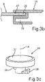
- Fig. 3b
- eine Schnittdarstellung eines Teilbereichs der Lüftungsvorrichtung im verbundenen Zustand mit einem Deckel eines Lebensmittel-Aufnahmebehälters;
- Fig. 3c
- eine perspektivische Darstellung eines Ausführungsbeispiels eines Drehelements der Lüftungsvorrichtung;
- Fig. 4
- eine perspektivische Schnittdarstellung durch die Lüftungsvorrichtung gemäß
Fig. 3a im zusammengebauten Zustand mit einer Klappe in der geschlossenen Stellung; - Fig. 5
- eine Schnittdarstellung der zusammengebauten Ausgestaltung gemäß
Fig. 3a im Bereich des Drehelements; - Fig. 6
- eine perspektivische Schnittdarstellung durch die Lüftungsvorrichtung gemäß
Fig. 3a im zusammengebauten Zustand mit der Klappe in der geöffneten Stellung; - Fig. 7
- eine Schnittdarstellung der zusammengebauten Lüftungsvorrichtung gemäß
Fig. 3a im Bereich des Drehelements; - Fig. 8
- eine weitere perspektivische Schnittdarstellung der zusammengebauten Lüftungsvorrichtung gemäß
Fig. 3a im Bereich des Drehelements mit geschlossener Klappe; - Fig. 9
- die Darstellung gemäß
Fig. 8 mit geschlossener Klappe; - Fig. 10
- eine schematische Frontansicht eines Teilbereichs des Haushaltskältegeräts mit einem zu
Fig. 2 unterschiedlichen Ausführungsbeispiel einer Lüftungsvorrichtung; - Fig. 11
- eine Explosionsdarstellung von Teilkomponenten der Lüftungsvorrichtung gemäß
Fig. 10 ; - Fig. 12
- eine perspektivische Schnittdarstellung der zusammengebauten Lüftungsvorrichtung gemäß
Fig. 11 in geschlossenem Zustand der Klappe; - Fig. 13
- eine Schnittdarstellung der zusammengebauten Lüftungsvorrichtung gemäß
Fig. 11 im Bereich des als Walze ausgebildeten Drehelements; - Fig. 14
- eine perspektivische Schnittdarstellung der zusammengebauten Lüftungsvorrichtung gemäß
Fig. 11 bei geschlossener Klappe; und - Fig. 15
- eine Schnittdarstellung der zusammengebauten Lüftungsvorrichtung gemäß
Fig. 11 im Bereich der Walze bei geöffneter Klappe.
- Fig. 1
- a perspective view of an embodiment of a household refrigerator according to the invention;
- Fig. 2
- a front view of subcomponents of the household refrigerator according to
Fig. 1 with an embodiment of a ventilation device, wherein the flap of the ventilation device is closed; - Fig. 3a
- an exploded view of subcomponents of the ventilation device according to a first embodiment;
- Figure 3b
- a sectional view of a partial area of the ventilation device in the connected state with a lid of a food receptacle;
- Figure 3c
- a perspective view of an embodiment of a rotary element of the ventilation device;
- Fig. 4
- a perspective sectional view through the ventilation device according to FIG
Fig. 3a when assembled with a flap in the closed position; - Fig. 5
- a sectional view of the assembled configuration according to
Fig. 3a in the area of the rotating element; - Fig. 6
- a perspective sectional view through the ventilation device according to FIG
Fig. 3a in the assembled state with the flap in the open position; - Fig. 7
- a sectional view of the assembled ventilation device according to FIG
Fig. 3a in the area of the rotating element; - Fig. 8
- a further perspective sectional view of the assembled ventilation device according to FIG
Fig. 3a in the area of the rotating element with the flap closed; - Fig. 9
- the representation according to
Fig. 8 with closed flap; - Fig. 10
- a schematic front view of a portion of the household refrigerator with a to
Fig. 2 different embodiment of a ventilation device; - Fig. 11
- an exploded view of subcomponents of the ventilation device according to
Fig. 10 ; - Fig. 12
- a perspective sectional view of the assembled ventilation device according to FIG
Fig. 11 when the flap is closed; - Fig. 13
- a sectional view of the assembled ventilation device according to FIG
Fig. 11 in the area of the rotating element designed as a roller; - Fig. 14
- a perspective sectional view of the assembled ventilation device according to FIG
Fig. 11 with the flap closed; and - Fig. 15
- a sectional view of the assembled ventilation device according to FIG
Fig. 11 in the area of the roller with the flap open.
In den Figuren werden gleiche oder funktionsgleiche Elemente mit den gleichen Bezugszeichen versehen.Identical or functionally identical elements are provided with the same reference symbols in the figures.
In
Der weitere Aufnahmeraum 5 dient im Allgemeinen zum Tiefgefrieren von Gefriergut, bei beispielsweise -18 °C. Der Aufnahmeraum 5 ist bei geöffneter Gefrierraumtür 7 zugänglich.The
In dem oberen Aufnahmeraum 4 ist ein Kühlgut- beziehungsweise Frischhaltebehälter ausziehbar gelagert, der einen Deckel 9 und eine Schublade bzw. Schale 10 aufweist. Über dem Deckel 9 kann, wie dargestellt, eine zusätzliche, separate Abdeckung 11 beispielsweise in Form einer Trennwand, beispielsweise eines Glasfachbodens, angeordnet sein. Der Frischhaltebehälter stellt einen Lebensmittel-Aufnahmebehälter 8 dar.In the
Der Innenbehälter 3 weist, unter anderem, zwei gegenüberliegende vertikale Seitenwände 3a und 3b auf.The
Zumindest durch die Abdeckung 11 ist der Lebensmittel-Aufnahmebehälter 8 von dem verbleibenden restlichen Teilvolumen des Aufnahmeraums 4 separiert.At least by the
Der Lebensmittel-Aufnahmebehälter 8 kann zerstörungsfrei lösbar aus dem Aufnahmeraum 4 entnommen werden. Auch im eingebrachten Zustand in dem Aufnahmeraum 4 ist vorgesehen, dass die Schale 10 in Tiefenrichtung und somit in z-Richtung im noch im Aufnahmeraum 4 gelagerten Zustand hin- und hergeschoben werden kann, um in das Innere der Schale 10 gelangen zu können.The
In
Die Lüftungsvorrichtung 12 weist eine Klappe 14 auf, die um eine in Breitenrichtung (x-Richtung) orientierte Schwenkachse B verschwenkbar ist. Die Klappe 14 erstreckt sich, wie dies in
In
Darüber hinaus ist vorgesehen, dass ein in Tiefenrichtung bemessener Freiraum zwischen dem vorderen Rand des Deckels 9 und einem hinteren Rand 17 eines Frontflansches 18 einer Frontwand 19 der Schale 10 durch diese Lüftungsvorrichtung 12 abgedeckt ist. Die Lüftungsvorrichtung 12 weist des Weiteren ein Betätigungselement in Form eines Drehelements 20 auf. Das Drehelement 20 ist in dem gezeigten Ausführungsbeispiel um eine Drehachse A drehbar. Das Drehelement 20 ist bereichsweise erhaben oberhalb der Klappe 14 angeordnet. Die Drehachse A ist insbesondere in Höhenrichtung (y-Richtung) des Lebensmittel-Aufnahmebehälters 8 orientiert. Das Drehelement 20 ist im Ausführungsbeispiel mit einem als Flachzylinder ausgebildeten, greifbaren Betätigungselement ausgebildet. Dies bedeutet, dass eine Höhe seiner Mantelwand 21 kleiner ist, als die radialen Ausmaße einer Oberfläche 22. Der Flachzylinder des Drehelements 20 kann durch einen Nutzer direkt mit den Fingern gegriffen werden, insbesondere an der Mantelwand 21. Durch eine derartige Drehbewegung des Drehelements 20 kann eine Schwenkbewegung der plattenartigen Klappe 14 um eine Schwenkachse B erfolgen. Die Schwenkachse B ist hier in Breitenrichtung (x-Richtung) orientiert. Die einstückige Klappe 14 ist insbesondere aus Kunststoff.In addition, it is provided that a free space measured in the depth direction between the front edge of the
Wie in dem Ausführungsbeispiel gemäß
Insbesondere ist die Drehachse B an einem vorderen Ende 23 der Klappe 14 ausgebildet. Ein hinteres Ende 24 der Klappe 14 kann somit frei nach unten geschwenkt werden.In particular, the axis of rotation B is formed on a
In
In
Darüber hinaus weist diese hintere Leiste 16 eine weitere Nut 29 auf. Diese ist nach vorne hin geöffnet. Sie ist zur Aufnahme von zumindest einem Lüftungsgitter 30 ausgebildet. Es können auch mehrere Lüftungsgitter 30 und 31 vorgesehen sein. Diese separaten Komponenten können mit entsprechenden rückseitigen Stegen in die Nut 29 eingesteckt werden. Durch diese Lüftungsgitter 30, 31 sind mehrere Lüftungskanäle 32 gebildet, von denen in
In
Darüber hinaus weist die Lüftungsvorrichtung 12 die bereits angesprochene Klappe 14 auf. Diese weist eine Längsachse C auf. Die Längsachse C verläuft parallel zur Drehachse B. Wie zu erkennen ist, weist die Klappe 14 in einem Querschnitt senkrecht zu ihrer Längsachse C eine dreieckige Form auf. Zusätzlich zur ebenen Oberseite 25 sind diesbezüglich eine schräg gestellte Vorderflanke 39 und eine daran anschließende schräg orientierte Hinterflanke 40 auf.In addition, the
Die Stellnocke 36 stellt ein Beispiel für ein Koppelteil dar, mit welchem das Drehelement 20 direkt mit der Klappe 14 gekoppelt ist. Insbesondere greift bei einer Drehbewegung des Drehelements 20 dieses Koppelteil in Form der Stellnocke 36 an der unebenen Unterseite der Klappe 14, insbesondere der Hinterflanke 40 an. Durch deren Schrägstellung wird die Klappe 14 bei einem Entlanggleiten der Stellnocke 36 an der Hinterflanke 40 um die Schwenkachse B verschwenkt. Darüber hinaus ist zu erkennen, dass die Klappe 14 eine durchgängige Aussparung 41 aufweist. Diese ist insbesondere zum hinteren Ende beziehungsweise zum hinteren Rand 24 als offene Aussparung ausgebildet. In diese Aussparung 41 kann sich das Drehelement 20 mit seinem Elementstamm 34 hineinerstrecken beziehungsweise nach hinten hindurch erstrecken. Der Flachzylinder 37 beziehungsweise das flachzylinderförmige obere Teilelement bleibt dabei oberhalb der Klappe 14 positioniert.The adjusting
Der Elementstamm 34 kann in dem Zusammenhang als Beispiel für einen Koppelstift des Drehelements 20 gesehen werden. Der Flachzylinder 37 ist als ein Beispiel für einen flachzylinderförmigen Drehkopf des Drehelements 20 zu verstehen.The element stem 34 can be seen in the context as an example of a coupling pin of the
Die Lüftungsvorrichtung 12 weist in einer vorteilhaften Ausführung des Weiteren seitliche Aufnahmen 42 und 43 auf. Diese dienen einerseits als Drehlager für die Klappe 14. Insbesondere können dazu Stifte 44 und 45, die mit der Klappe 14 insbesondere einstückig verbunden sind, in entsprechende Aufnahmen 46 eingeführt werden. Darüber hinaus dienen diese seitlichen Aufnahmen 42, 43 auch noch zur Befestigung der hinteren Schiene bzw. Leiste 16. Des Weiteren kann eine vordere Schiene bzw. Leiste 47 der Lüftungsvorrichtung 12 daran befestigt werden. Insbesondere sind in dem Zusammenhang Steckverbindungen vorgesehen. So kann ein hinteres Einführelement 48 an den Aufnahmen 42 und 43 in die Nut 29 haltend eingesteckt werden. Ebenso kann ein vorderes Einführelement 49 der seitlichen Aufnahmen 42, 43 in eine Nut 50 der einstückigen vorderen Leiste 47 eingeführt werden.In an advantageous embodiment, the
In
In
In
In
In
In
In
In
Darüber hinaus ist eine vordere Leiste 47 vorgesehen. Diese kann ebenfalls baugleich zur vorderen Leiste 47 in
Die mechanische Verbindung der seitlichen Aufnahmen 42 und 43 mit den beiden Leisten 16 und 47 kann entsprechend der Erläuterung in
Darüber hinaus ist auch hier ein Sockel 33 vorgesehen. Dieser Sockel 33 weist hier eine Feder 58 auf. Diese drückt auf Abflachungen 59 und 60 einer Mantelwand 61 der Walze 57. Dadurch kann sich die Drehwalze 57 nur zwischen zwei Stellpositionen bewegen. Wird die Walze 57 nach vorne um einen spezifischen Winkel, beispielsweise zwischen 50° und 70°, insbesondere um 60°, verdreht, so können die als Flügel ausgebildeten Teilelemente 55 und 56 individuell in ihrer Stellung verstellt werden. Die Drehachse A der Walze 57 ist hier horizontal orientiert, insbesondere in Breitenrichtung des Lebensmittel-Aufnahmebehälters. Insbesondere ist die Drehachse A koaxial mit der Drehachse B der Klappe 14. Wie zu erkennen ist, sind die beiden Teilelemente 55 und 56 in Richtung dieser Drehachse B betrachtet an gegenüberliegenden Enden der Walze 57 angeordnet. Insbesondere ist hier eine drehfeste Verbindung zwischen der Walze 57 und den Teilelementen 55 und 56 gebildet. Die Teilelemente 55 und 56 sind an den der Walze 57 abgewandten Enden mit den seitlichen Aufnahmen 42 und 43 verbunden, insbesondere drehbar darin gelagert.In addition, a
In
In der geschlossenen Stellung der Klappe 14 ist eine Dreieckspitze 63 direkt benachbart zu einem hinteren Begrenzungsrand 65 der Lüftungsöffnung 51 angeordnet. Entsprechend ist die Dreieckspitze 64 unmittelbar benachbart zu einem vorderen Begrenzungsrand 66 der Lüftungsöffnung 51 ausgebildet. Dadurch ist der geschlossene Zustand beziehungsweise die geschlossene Stellung erreicht. Die dritte Dreieckspitze 62 ist bei dieser geschlossenen Stellung nach unten weisend angeordnet.In the closed position of the
In
- 11
- HaushaltskältegerätHousehold refrigerator
- 22
- KorpusBody
- 33
- InnenbehälterInner container
- 3a3a
- vertikale Seitenwandvertical side wall
- 3b3b
- vertikale Seitenwandvertical side wall
- 44th
- AufnahmeraumRecording room
- 55
- AufnahmeraumRecording room
- 66th
- Türdoor
- 77th
- GefrierraumtürFreezer door
- 88th
- Lebensmittel-AufnahmebehälterFood receptacle
- 99
- Deckelcover
- 1010
- SchaleBowl
- 1111
- Abdeckungcover
- 1212th
- LüftungsvorrichtungVentilation device
- 1313th
- InneresInterior
- 1414th
- Klappeflap
- 1515th
- DeckelmodulCover module
- 1616
- Leistestrip
- 1717th
- hinterer Randrear edge
- 1818th
- FrontflanschFront flange
- 1919th
- FrontwandFront wall
- 2020th
- DrehelementRotary element
- 2121
- MantelwandCladding wall
- 2222nd
- Oberflächesurface
- 2323
- vorderes Endefront end
- 2424
- hinteres Enderear end
- 2525th
- OberseiteTop
- 2626th
- OberseiteTop
- 2727
- NutGroove
- 2828
- vorderer Randleading edge
- 2929
- NutGroove
- 3030th
- LüftungsgitterVentilation grille
- 3131
- LüftungsgitterVentilation grille
- 3232
- LüftungskanalVentilation duct
- 3333
- Sockelbase
- 3434
- ElementstammElement stem
- 3535
- AufsatzEssay
- 3636
- StellnockeAdjusting cam
- 3737
- FlachzylinderFlat cylinder
- 3838
- ArretierelementLocking element
- 3939
- VorderflankeLeading flank
- 4040
- HinterflankeBack flank
- 4141
- AussparungRecess
- 4242
- Aufnahmeadmission
- 4343
- Aufnahmeadmission
- 4444
- Stiftpen
- 4545
- Stiftpen
- 4646
- Aufnahmeadmission
- 4747
- Schienerail
- 4848
- EinführelementIntroducer
- 4949
- EinführelementIntroducer
- 5050
- NutGroove
- 5151
- LüftungsöffnungVentilation opening
- 5252
- VerstauraumStorage space
- 5353
- V-SpitzeV-tip
- 5454
- LüftungsöffnungVentilation opening
- 5555
- TeilelementSub-element
- 5656
- TeilelementSub-element
- 5757
- Walzeroller
- 5858
- Federfeather
- 5959
- AbflachungFlattening
- 6060
- AbflachungFlattening
- 6161
- MantelwandCladding wall
- 6262
- DreieckspitzeTriangle point
- 6363
- DreieckspitzeTriangle point
- 6464
- DreieckspitzeTriangle point
- 6565
- BegrenzungsrandBoundary
- 6666
- BegrenzungsrandBoundary
- MM.
- MittelpunktFocus
- AA.
- Achseaxis
- BB.
- Achseaxis
- CC.
- Achseaxis
Claims (15)
Applications Claiming Priority (1)
| Application Number | Priority Date | Filing Date | Title |
|---|---|---|---|
| DE102019214592.2A DE102019214592A1 (en) | 2019-09-24 | 2019-09-24 | Food receptacle with a specially shaped flap of a ventilation device, as well as a household refrigerator |
Publications (1)
| Publication Number | Publication Date |
|---|---|
| EP3798547A1 true EP3798547A1 (en) | 2021-03-31 |
Family
ID=72292376
Family Applications (1)
| Application Number | Title | Priority Date | Filing Date |
|---|---|---|---|
| EP20193631.7A Pending EP3798547A1 (en) | 2019-09-24 | 2020-08-31 | Food storage container with a specifically shaped flap of a ventilation device and domestic refrigerator |
Country Status (2)
| Country | Link |
|---|---|
| EP (1) | EP3798547A1 (en) |
| DE (1) | DE102019214592A1 (en) |
Citations (5)
| Publication number | Priority date | Publication date | Assignee | Title |
|---|---|---|---|---|
| WO2004038312A1 (en) | 2002-10-23 | 2004-05-06 | Lg Electronics Inc. | Vegetable room for refrigerator |
| DE102012221496A1 (en) * | 2012-11-23 | 2014-05-28 | BSH Bosch und Siemens Hausgeräte GmbH | Domestic refrigerating appliance with an actuating means for a container lid |
| WO2015082277A1 (en) * | 2013-12-06 | 2015-06-11 | BSH Hausgeräte GmbH | Domestic cooling appliance comprising a control element for adjusting a cover of a crisper drawer, which can be stopped in three different positions |
| CN107747840A (en) * | 2017-10-18 | 2018-03-02 | 合肥华凌股份有限公司 | Refrigerator compartment humidity regulation mechanism and refrigerator |
| CN108592509A (en) * | 2018-04-25 | 2018-09-28 | 海信(山东)冰箱有限公司 | A kind of refrigerator with humidity regulation drawer |
Family Cites Families (3)
| Publication number | Priority date | Publication date | Assignee | Title |
|---|---|---|---|---|
| CN205227969U (en) * | 2015-10-29 | 2016-05-11 | 博西华电器(江苏)有限公司 | Refrigerating equipment |
| TR201712278A1 (en) * | 2017-08-17 | 2019-03-21 | Arcelik As | MOISTURE CONTROLLED REFRIGERATOR WITH VEGETABLES |
| CN108088166B (en) * | 2017-12-07 | 2019-11-22 | 合肥华凌股份有限公司 | Article-storage device and refrigerator |
-
2019
- 2019-09-24 DE DE102019214592.2A patent/DE102019214592A1/en active Pending
-
2020
- 2020-08-31 EP EP20193631.7A patent/EP3798547A1/en active Pending
Patent Citations (5)
| Publication number | Priority date | Publication date | Assignee | Title |
|---|---|---|---|---|
| WO2004038312A1 (en) | 2002-10-23 | 2004-05-06 | Lg Electronics Inc. | Vegetable room for refrigerator |
| DE102012221496A1 (en) * | 2012-11-23 | 2014-05-28 | BSH Bosch und Siemens Hausgeräte GmbH | Domestic refrigerating appliance with an actuating means for a container lid |
| WO2015082277A1 (en) * | 2013-12-06 | 2015-06-11 | BSH Hausgeräte GmbH | Domestic cooling appliance comprising a control element for adjusting a cover of a crisper drawer, which can be stopped in three different positions |
| CN107747840A (en) * | 2017-10-18 | 2018-03-02 | 合肥华凌股份有限公司 | Refrigerator compartment humidity regulation mechanism and refrigerator |
| CN108592509A (en) * | 2018-04-25 | 2018-09-28 | 海信(山东)冰箱有限公司 | A kind of refrigerator with humidity regulation drawer |
Also Published As
| Publication number | Publication date |
|---|---|
| DE102019214592A1 (en) | 2021-03-25 |
Similar Documents
| Publication | Publication Date | Title |
|---|---|---|
| EP3014203B1 (en) | Domestic refrigerator having a keep-fresh container located in an interior and having a cover which can be raised and lowered by way of a rotatable operating element | |
| EP2923161B1 (en) | Domestic refrigeration appliance with actuation means for a container lid | |
| EP3014202B1 (en) | Domestic refrigerator having a keep-fresh container and an operating element designed in the form of a push/push locking mechanism for moving a cover for the keep-fresh container | |
| EP3798551B1 (en) | Domestic refrigerator and food storage container with support rail in which a movable flap is mounted | |
| EP3168554A1 (en) | Domestic household refrigeration device comprising a keep-fresh container, the front wall of which is an outer wall of the device | |
| EP3798546B1 (en) | Food storage container with a specifically shaped flap of a ventilation device and domestic refrigerator | |
| EP3798547A1 (en) | Food storage container with a specifically shaped flap of a ventilation device and domestic refrigerator | |
| WO2015082279A1 (en) | Domestic refrigeration appliance having a keep-fresh container that is located in an interior and has a cover which can be raised and lowered by way of an operating element in a drawer | |
| EP3014199B1 (en) | Household cooling appliance comprising an inner chamber and a keep-fresh container having a lid with a forwards-opening guide rail | |
| EP3014204B1 (en) | Domestic refrigerator having a keep-fresh container and an operating element and a movement-guiding device | |
| EP3798548A1 (en) | Food storage container with specific ventilation device with preassembly unit, and domestic refrigerator and method | |
| EP3809079B1 (en) | Domestic refrigerator and food storage container with pivotable flap on the tray | |
| EP3809069B1 (en) | Food storage container with a slide of a ventilation device which can be moved in the depth direction and a domestic refrigerator | |
| EP3163229B1 (en) | Household refrigerator with individually creatable auxiliary compartment and method for producing an auxiliary compartment | |
| EP2218991B1 (en) | Cooler with at least one coolant box | |
| DE102020202044B3 (en) | Food receptacle with specific coupling of a lid with a ventilation device, as well as a method | |
| EP3798549A1 (en) | Food storage container with tray and specific lid and a domestic refrigerator | |
| EP3951296A1 (en) | Carrier device with a specifically snapped guide rail for a bearing shell, food absorbent container and method | |
| EP4086545A1 (en) | Domestic refrigerator and food storage container with an air-conditioning device with a specific adjustment part between a shell and an attachment | |
| DE102020209318A1 (en) | Food storage containers with a specific handle of an air conditioning device, as well as household refrigeration appliance | |
| EP4283227A1 (en) | Domestic refrigeration appliance having a stabilized anti-tilt and anti-pullout stop device for a food receptacle | |
| EP3751220A1 (en) | Partitioning plate for a household refrigerating appliance with an opening-closing device for a ventilation opening and a household refrigerating appliance | |
| DE102021204416A1 (en) | Food storage container with an air conditioning device with specific adjustment between a tray and a top, and household refrigeration appliance | |
| DE102021206173A1 (en) | Food storage container, comprising an air conditioning device with a specific operating status display, and domestic refrigeration appliance | |
| DE102011006806A1 (en) | Refrigerating appliance, in particular household refrigerating appliance |
Legal Events
| Date | Code | Title | Description |
|---|---|---|---|
| PUAI | Public reference made under article 153(3) epc to a published international application that has entered the european phase |
Free format text: ORIGINAL CODE: 0009012 |
|
| STAA | Information on the status of an ep patent application or granted ep patent |
Free format text: STATUS: THE APPLICATION HAS BEEN PUBLISHED |
|
| AK | Designated contracting states |
Kind code of ref document: A1 Designated state(s): AL AT BE BG CH CY CZ DE DK EE ES FI FR GB GR HR HU IE IS IT LI LT LU LV MC MK MT NL NO PL PT RO RS SE SI SK SM TR |
|
| AX | Request for extension of the european patent |
Extension state: BA ME |
|
| STAA | Information on the status of an ep patent application or granted ep patent |
Free format text: STATUS: REQUEST FOR EXAMINATION WAS MADE |
|
| 17P | Request for examination filed |
Effective date: 20210930 |
|
| RBV | Designated contracting states (corrected) |
Designated state(s): AL AT BE BG CH CY CZ DE DK EE ES FI FR GB GR HR HU IE IS IT LI LT LU LV MC MK MT NL NO PL PT RO RS SE SI SK SM TR |
|
| STAA | Information on the status of an ep patent application or granted ep patent |
Free format text: STATUS: EXAMINATION IS IN PROGRESS |
|
| 17Q | First examination report despatched |
Effective date: 20230417 |