EP3798384A1 - Panneaux de construction - Google Patents
Panneaux de construction Download PDFInfo
- Publication number
- EP3798384A1 EP3798384A1 EP19199233.8A EP19199233A EP3798384A1 EP 3798384 A1 EP3798384 A1 EP 3798384A1 EP 19199233 A EP19199233 A EP 19199233A EP 3798384 A1 EP3798384 A1 EP 3798384A1
- Authority
- EP
- European Patent Office
- Prior art keywords
- locking
- panel
- edge
- strip
- tongue
- Prior art date
- Legal status (The legal status is an assumption and is not a legal conclusion. Google has not performed a legal analysis and makes no representation as to the accuracy of the status listed.)
- Withdrawn
Links
Images


Classifications
-
- E—FIXED CONSTRUCTIONS
- E04—BUILDING
- E04F—FINISHING WORK ON BUILDINGS, e.g. STAIRS, FLOORS
- E04F15/00—Flooring
- E04F15/02—Flooring or floor layers composed of a number of similar elements
- E04F15/02038—Flooring or floor layers composed of a number of similar elements characterised by tongue and groove connections between neighbouring flooring elements
-
- E—FIXED CONSTRUCTIONS
- E04—BUILDING
- E04F—FINISHING WORK ON BUILDINGS, e.g. STAIRS, FLOORS
- E04F13/00—Coverings or linings, e.g. for walls or ceilings
- E04F13/07—Coverings or linings, e.g. for walls or ceilings composed of covering or lining elements; Sub-structures therefor; Fastening means therefor
- E04F13/08—Coverings or linings, e.g. for walls or ceilings composed of covering or lining elements; Sub-structures therefor; Fastening means therefor composed of a plurality of similar covering or lining elements
- E04F13/0889—Coverings or linings, e.g. for walls or ceilings composed of covering or lining elements; Sub-structures therefor; Fastening means therefor composed of a plurality of similar covering or lining elements characterised by the joints between neighbouring elements, e.g. with joint fillings or with tongue and groove connections
- E04F13/0894—Coverings or linings, e.g. for walls or ceilings composed of covering or lining elements; Sub-structures therefor; Fastening means therefor composed of a plurality of similar covering or lining elements characterised by the joints between neighbouring elements, e.g. with joint fillings or with tongue and groove connections with tongue and groove connections
-
- E—FIXED CONSTRUCTIONS
- E04—BUILDING
- E04F—FINISHING WORK ON BUILDINGS, e.g. STAIRS, FLOORS
- E04F15/00—Flooring
- E04F15/02—Flooring or floor layers composed of a number of similar elements
- E04F15/10—Flooring or floor layers composed of a number of similar elements of other materials, e.g. fibrous or chipped materials, organic plastics, magnesite tiles, hardboard, or with a top layer of other materials
- E04F15/107—Flooring or floor layers composed of a number of similar elements of other materials, e.g. fibrous or chipped materials, organic plastics, magnesite tiles, hardboard, or with a top layer of other materials composed of several layers, e.g. sandwich panels
-
- E—FIXED CONSTRUCTIONS
- E04—BUILDING
- E04F—FINISHING WORK ON BUILDINGS, e.g. STAIRS, FLOORS
- E04F2201/00—Joining sheets or plates or panels
- E04F2201/01—Joining sheets, plates or panels with edges in abutting relationship
- E04F2201/0138—Joining sheets, plates or panels with edges in abutting relationship by moving the sheets, plates or panels perpendicular to the main plane
- E04F2201/0146—Joining sheets, plates or panels with edges in abutting relationship by moving the sheets, plates or panels perpendicular to the main plane with snap action of the edge connectors
-
- E—FIXED CONSTRUCTIONS
- E04—BUILDING
- E04F—FINISHING WORK ON BUILDINGS, e.g. STAIRS, FLOORS
- E04F2201/00—Joining sheets or plates or panels
- E04F2201/01—Joining sheets, plates or panels with edges in abutting relationship
- E04F2201/0153—Joining sheets, plates or panels with edges in abutting relationship by rotating the sheets, plates or panels around an axis which is parallel to the abutting edges, possibly combined with a sliding movement
-
- E—FIXED CONSTRUCTIONS
- E04—BUILDING
- E04F—FINISHING WORK ON BUILDINGS, e.g. STAIRS, FLOORS
- E04F2201/00—Joining sheets or plates or panels
- E04F2201/02—Non-undercut connections, e.g. tongue and groove connections
- E04F2201/023—Non-undercut connections, e.g. tongue and groove connections with a continuous tongue or groove
-
- E—FIXED CONSTRUCTIONS
- E04—BUILDING
- E04F—FINISHING WORK ON BUILDINGS, e.g. STAIRS, FLOORS
- E04F2201/00—Joining sheets or plates or panels
- E04F2201/04—Other details of tongues or grooves
- E04F2201/042—Other details of tongues or grooves with grooves positioned on the rear-side of the panel
-
- E—FIXED CONSTRUCTIONS
- E04—BUILDING
- E04F—FINISHING WORK ON BUILDINGS, e.g. STAIRS, FLOORS
- E04F2201/00—Joining sheets or plates or panels
- E04F2201/04—Other details of tongues or grooves
- E04F2201/043—Other details of tongues or grooves with tongues and grooves being formed by projecting or recessed parts of the panel layers
-
- E—FIXED CONSTRUCTIONS
- E04—BUILDING
- E04F—FINISHING WORK ON BUILDINGS, e.g. STAIRS, FLOORS
- E04F2201/00—Joining sheets or plates or panels
- E04F2201/05—Separate connectors or inserts, e.g. pegs, pins, keys or strips
- E04F2201/0511—Strips or bars, e.g. nailing strips
-
- E—FIXED CONSTRUCTIONS
- E04—BUILDING
- E04F—FINISHING WORK ON BUILDINGS, e.g. STAIRS, FLOORS
- E04F2201/00—Joining sheets or plates or panels
- E04F2201/05—Separate connectors or inserts, e.g. pegs, pins, keys or strips
- E04F2201/0523—Separate tongues; Interlocking keys, e.g. joining mouldings of circular, square or rectangular shape
- E04F2201/0547—Separate tongues; Interlocking keys, e.g. joining mouldings of circular, square or rectangular shape adapted to be moved perpendicular to the joint edge
Definitions
- the disclosure generally relates to the field of mechanical locking systems for floor panels and building panels.
- Laminate flooring usually comprise a core of a 6-12 mm fibre board, a 0,2-0,8 mm thick upper decorative surface layer of laminate and a 0,1-0,6 mm thick lower balancing layer of laminate, plastic, paper or like material.
- a laminate surface comprises melamine-impregnated paper.
- the most common core material is fibreboard with high density and good stability usually called HDF - High Density Fibreboard. Sometimes also MDF - Medium Density Fibreboard - is used as core.
- Laminate floor panels of this type have been joined mechanically by means of so-called mechanical locking systems. These systems comprise locking means, which lock the panels horizontally and vertically.
- the mechanical locking systems are usually formed by machining of the core of the panel.
- parts of the locking system may be formed of a separate material, for instance aluminium or HDF, which are integrated with the floor panel, i.e. joined with the floor panel in connection with the manufacture thereof.
- An overall objective of the present disclosure is to provide a building panel which facilitates improved control of moisture, such as water.
- Improved moisture control may include not limited to improved sealing between assembled building panels, improved resistance to water penetration through a surface comprising assembled building panels.
- Horizontal plane relates to a plane, which is parallel to the front surface. Directly adjoining upper parts of two neighboring joint edges of two joined floor panels together define a “ vertical plane " perpendicular to the horizontal plane.
- the outer parts of the floor panel at the edge of the floor panel between the front side and the rear side are called “ joint edge " .
- the joint edge has several " joint surfaces " which can be vertical, horizontal, angled, rounded, beveled etc. These joint surfaces exist on different materials, for instance laminate, fiberboard, wood, plastic, metal (in particular aluminum) or sealing materials.
- vertical locking is meant locking parallel to the vertical plane.
- horizontal locking is meant locking parallel to the horizontal plane.
- up is meant towards the front surface, by “down” towards the rear surface, by “inwardly” mainly horizontally towards an inner and centre part of the panel and by “outwardly” mainly horizontally away from the centre part of the panel.
- locking or " locking system” are meant cooperating connecting means which interconnect the floor panels vertically and/ or horizontally.
- mechanical locking system is meant that locking can take place without glue. Mechanical locking systems can in many cases also be joined by glue.
- vertical locking surfaces is meant the upper and lower cooperating tongue surfaces in the tongue in a first edge cooperating with upper and lower cooperating tongue groove surfaces in the tongue groove in an adjacent second edge locking the adjacent edges vertically.
- horizontal locking surfaces an essentially vertical upper tongue groove edge and a locking element in the second edge cooperating with an essentially vertical upper tongue edge and a locking groove in the adjacent first edge, the cooperating horizontal locking surfaces lock the adjacent edges horizontally.
- locking groove side is meant the side of the floor panel in which part of the horizontal locking consists of a locking groove whose opening faces to the rear side.
- locking element side is meant the side of the floor panel in which part of the horizontal locking consists of a locking element, which cooperates with the locking groove.
- decorative surface layer is meant a surface layer, which is mainly intended to give the floor its decorative appearance.
- Wear resistant surface layer relates to a high abrasive surface layer, which is mainly adapted to improve the durability of the front side. This conclude in that a “ decorative wear resistant surface layer " is a layer, which is intended to give the floor its decorative appearance as well as improve the durability of the front side. A surface layer is applied to the core.
- Embodiments of the present invention are particularly suitable for use in floating floors, which are formed of floor panels which are joined mechanically with a locking system integrated with the floor panel, i.e. mounted at the factory, are made up of one or more upper layers of wood or wood veneer, decorative laminate, powder based surfaces or decorative plastic material, an intermediate core of wood-fibre-based material or plastic material and preferably a lower balancing layer on the rear side of the core.
- Floor panels of solid wood or with a surface layer of cork, linoleum, rubber or soft wear layers, for instance needle felt glued to a board, printed and preferably also varnished surface and floors with hard surfaces such as stone, tile and similar materials are included.
- the long and short edges are mainly used to simplify the description of embodiments of the invention.
- the panels may be square. It should be emphasised that embodiments of the invention may be used in any floor panel and it may be combined with all types of known locking system formed on the long edges and/short edges, where the floor panels are intended to be joined using a mechanical locking system connecting the panels in the horizontal and/or vertical directions on at least two adjacent edges.
- a set of similar or essentially identical building panels such as a floor or wall panels, comprising a first mechanical locking system at respective opposite and parallel third and fourth edges, such as long edges.
- the first locking system comprising a first locking strip 13a at one of the third edge or fourth edge having a first locking element configured to cooperate for horizontal locking with a first locking groove at the other of the third or fourth edge of an adjacent building panel, preferably by means of a folding motion, and a second locking system at respective opposite and parallel first and second edges, such as short edges.
- the second locking system comprising a second locking strip at one of the first edge or second edge, having a second locking element configured to cooperate for horizontal locking with a second locking groove at the other of the first or second edge of an adjacent building panel.
- the thickness of the second locking strip in a thickness-direction of the building panel, exceeds the thickness of the first locking strip.
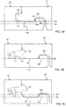
- FIG.1 A known building panel comprising mechanical locking systems is illustrated in FIG.1 .
- a mechanical locking system typically comprises a tongue and a tongue groove for vertical locking and a locking element and a locking groove for horizontal locking. It typically has at least four pairs of active cooperating locking surfaces, two pairs for vertical locking and two pairs for horizontal locking.
- the locking system comprises several other surfaces, which generally are not in contact with each other and can therefore be produced with considerably larger tolerance then the cooperating locking surfaces.
- Laminate floorings are usually composed of a core consisting of a 6 - 9 mm fiberboard, a 0.20 mm thick upper surface layer and a lower balancing layer.
- the surface layer provides appearance and durability to the floor panels.
- the core provides stability and the balancing layer keeps the board level when the relative humidity (RH) varies during the year.
- FIGS. 1, 2A-B and 3 illustrate according to prior art a typical first mechanical locking system (strip lock), which can be locked with angling and which is widely used on the market. Such a locking system can also be designed to be locked with vertical or horizontal snapping as will be explained herein.
- FIG.4 shows a vertical cross section of the floor panel is shown of a part of a long side 13' of the floor panel 50', as well as a part of a long side 14' of an adjoining floor panel 10'.
- the bodies of the floor panels 10', 50' can be composed of a fiberboard body or core, which supports here, a wear resistant and decorative surface layer on its front side and a balancing layer on its rear side (underside).
- the locking system has a tongue 14h' and a tongue groove 13j' which locks the panels in a vertical direction V with upper 53 and lower 56 tongue surfaces that cooperate with upper 43 and lower 46 tongue grooves surfaces.
- a locking strip 13a' is formed from the body and balancing layer of the floor panel 50' and supports a locking element 13b'. Therefore the locking strip 13a' and the locking element 13b' in a way constitute an extension of the lower part of the tongue groove 13j'.
- the locking element 13b' formed on the strip 13a' has an operative locking element surface 13m' which cooperates with an operative locking groove surface 14m' in a locking groove 14g' in the opposite locking groove side of the adjoining floor panel 10'.
- a known second locking system shown in FIGS 4B-C , can also be formed with a flexible tongue 11i' (fold lock) typically used at short edges 11', 12' as shown in FIGS 4B-C , which can be displaced during locking.
- a locking system can be locked with a vertical movement D1 as shown in FIG.3 .
- the upper surface 11c' of the second locking strip 11a' is disposed in one of: a common plane 60 to that of the first locking strip 13a' as derivable from comparing FIG.4A and FIG.4B , or a plane 61' disposed vertically displaced below the upper surface 13c' of the first locking strip 13a' i.e. towards the rear surface 16' of the panel, vertically below the plane 60', as derivable from comparing FIG. 4A and FIG.4C .
- the displaceable tongue 11i' is configured to cooperate with the second tongue groove 12j' for locking in a vertical direction.
- the displaceable tongue 11i' is a separate part and is made of, e.g., plastic, and inserted in a displacement groove 11k' at the first edge 11' of the first panel 10'.
- the tongue 11i' is pushed into a displacement groove 11k' during a vertical assembling of the first and the second edge of the first and the second panel.
- the displaceable tongue 11i' springs back and into the second tongue groove 12j' at the second edge 12' of the second panel 20' when the panels have reached a locked position.
- a third 13' and a fourth edge 14' of the panels are provided with the first locking system, which enables assembling to an adjacent panel 20' by an angling movement, to obtain a simultaneous assembling of the first 11' and the second 12' edges and the third 13' and the fourth edges 14' as shown in FIG.3 .
- a gap 66 is formed between locking strip 11a' of first edge 11' of first panel 10' and locking strip 13a' of the third edge 13' of adjacent panel 20'.
- moisture such as water
- first edge 11' of first panel 10' may penetrate between the first edge 11' of first panel 10' and the second edge 12' of the adjacent panel 20' via the gap 66.
- moisture which penetrate in between first edge 11' of first panel and second edge of an adjacent panel along the first edge 11' is collected by and/ accumulates on the second locking strip 11a' of the first panel and flows along the second locking strip 11a' to the gap 66, whereby the fluid penetrates to the rear surface 16' of the at panels comprised by the floor.
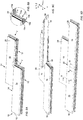
- FIGS. 4A shows a cross sectional view of a known first locking system typically provided on respective opposite and parallel long edges of a panel.
- FIGS. 4B-C show cross sections of different embodiments of known second locking systems typically provided on respective opposite and parallel short edges of a panel.
- an upper surface 13c' of locking strip 13a of the third edge is provided in a first plane 60.
- the distance Z1' in the Z-direction between the rear surface 16' and the upper surface 19.
- the distance Z2' in the Z-direction, between the rear surface 16' and an upper surface of the locking element 18'.
- an upper surface 11c' of locking strip 11a' of the first edge is provided in the first plane 60'.
- the upper surface 11c' of the locking strip 11a' is provided in the same plane as the upper surface 13c' of the locking strip 13a' of the third edge 13', such as a long edge.
- an upper surface 11c' of locking strip 11a' of the first edge is provided in a second plane 61.
- the second plane 61' being disposed vertically below the first plane 60', i.e. closer to the rear surface 16' than the first plane 60'.
- the third panel 30' with the first tongue groove 12j' is displaced in relation to the first panel 10' with the displaceable tongue 11i', which is pushed into a displacement groove 11k' by an edge of the third panel 30'.
- the displaceable tongue 11i" springs back, and into the second tongue groove 12j', when the panels have reached an assembled position, and locks the first and the third panels vertically.
- FIGS 5A-D , 6A-B , 7 and 8 Exemplary embodiments of the invention are shown in FIGS 5A-D , 6A-B , 7 and 8 .
- the fourth edge 14 may comprise a first locking protrusion 14e such as a locking tongue 14h, provided with a first lower edge surface 14f.
- the second locking system may be formed with a tonuge and groove configuration.
- the second edge 12 may provided with a second locking protrusion 12e, provided with a second lower edge surface 12f as shown in FIG. 8 .
- first and second lower edge surfaces 12f, 14f are configured to cooperate with a respective of the first and second upper surfaces 11c, 13c of a first and a second locking strip 13a, 11a of adjacent panel, such as the second 20 or third panel 30 as shown for instance in FIG.7 or FIG.8 respectively.
- the second mechanical locking system may be formed at one of a first 11 or second 12 short edge, such as a first edge, of similar, preferably essentially identical panels 10, 20, 30, 40, 50.
- the second mechanical locking system may be configured for locking the first edge 11 of a first panel 10 to the second edge of an adjacent panel, such as the third panel 30, in a plane, and in a vertical and/or in horizontal directions perpendicular said first and second edge towards and away from each other.
- An embodiment of the second mechanical locking system enables assembling of the first and the third panels by vertical folding of the second edge of the third panel 30 relative the first edge 11 of the first panel 10.
- the term vertical folding may entail that the second locking system is configured to enable assembling of panels to obtain a locking position by means a vertical motion, such as parallel displacement of the panel 30, such as a plane of the panel 30, which may be include the plane of the front surface 15.
- a vertical motion such as parallel displacement of the panel 30, such as a plane of the panel 30, which may be include the plane of the front surface 15.
- vertical motion as used herein may include vertical folding.
- the mechanical locking systems are preferably formed by mechanical cutting, such as milling, drilling and/or sawing, of the edges of the panels and may according to embodiments be provided with a displaceable tongue 11i, preferably of plastic.
- the displaceable tongue 11i may be bendable and provided with protruding bendable parts, such as the displaceable tongues disclosed in WO2006/043893 and WO2007/015669 .
- the displaceable tongue 11i may also be configured to be locked by a movement along the first and the second edge, such as the displaceable tongues disclosed in WO2009/116926 and WO200/8004960 .
- Each panel may be of a rectangular shape and the first mechanical locking system may comprise a first tongue groove 13j at one of a third edge 13 or fourth 14 long edge, for example the third edge 13, and a first locking tongue 14h at the other of the third or fourth edge, for example the fourth edge 14.
- the first locking tongue 14h and the first tongue groove 13j may be configured to cooperate for locking of the third and the fourth edge 13, 14 in a vertical V direction.
- the first mechanical locking system may typically further comprise a first locking strip 13a at the third edge 13, provided with a vertically protruding first locking element 13b, a first locking groove 14g at a fourth edge 14.
- the first locking element 13b is configured to cooperate with the first locking groove 14g for locking of the third 13 and the fourth edge 14 in a horizontal direction, in particular away from each other and perpendicular said third and fourth edge, as is shown in e.g. FIG. 7 .
- the second mechanical locking system shown for instance in FIG. 8 may comprise a second locking strip 11a at the first edge 11 provided with a vertically protruding second locking element 11b and a second locking groove 12g at a second edge 12.
- Embodiments of the second locking system may comprise a second locking tongue, preferably in the shape of a displaceable tongue 11i arranged in a displacement groove 11k at the first edge 11 of the first panel 10.
- the displaceable tongue 11i is configured to cooperate with a first tongue groove 12j formed at the other of the first 11 or second edge 12, for locking of the first and the second edge 11, 12 in a vertical V direction.
- the second locking system may alternatively comprise a tongue and groove configuration similar to the first locking system, i.e. with the locking tongue integrally formed with the panel.
- the second edge 12 may be provided with a second locking protrusion 12e configured to be received in the second locking strip 11a for horizontal locking of the first edge of a panel to the second edge of an adjacent panel.
- the second locking protrusion 12e may be provided with a second lower edge surface 12f configured to face a second upper surface 11c of an adjacent second panel when the respective second locking system of the first and second panel are configured in locking engagement with each other.
- the second lower edge surface 12 may according to some embodiments abut the second upper surface 11c when two panels are configured in locking engagement.
- the second lower edge surface 12f may be configured to cooperate with a second upper surface 11c of the second locking strip 11a of an adjacent panel 30.
- the first lower edge surface 12m of the building panel is therefore according to some embodiments arranged in the same plane 61 as the first upper surface 11c of the first locking strip 11a when the first and second edge of two adjacent panels are configured in locking engagement with each other.
- the fourth edge 14 is may be provided with a first locking protrusion 14e, which may form part of the first locking tongue 14h, and comprising a first lower edge surface 14f configured to cooperate with a first upper surface 13c of the first locking strip 13a of an adjacent panel 20.
- the lower edge surface 14f of the building panel may therefore according to embodiments be arranged in the same plane 60 as the first upper surface 13c of the first locking strip 13a.
- the second locking strip 11a may extend, in the width-direction W, along the entire front surface 15 of the panel 10. It is thus facilitated that the second locking strip 11a may at least to some extent overlap or partially overlap or completely overlap the first locking strip 13a of an adjacent panel 20 when panels 10 and 20 are assembled in locking position by means of the first locking system, i.e. along the long edges.
- the second locking strip 11a may at least partially overlap or fully cross the first locking element 13b of the adjacent panel 20 when the panels 10, 20 are assembled in locked position by means of the first mechanical locking system.
- the configuration facilitates that an end portion of the second strip 11a may abut the core 17 of the adjacent panel 20 inboard the first locking element 13b, as shown in FIG.5B . Thereby, improved sealing may be facilitated.
- the first edge 11 and the second edge 12 may be respective short edges, such as shortest edges, of the building panel 10.
- the third edge 13 and the fourth edge 14 may be respective long edges, such as longest edges, of the building panel 10.
- the distance Z3, in this case the thickness of the second locking strip 11a, in a thickness direction Z, may exceed than the distance Z1, in this case the thickness of the first locking strip 11a shown in FIGS 7 .
- the rear surface 16 of the panel may extend in a first plane 60.
- the upper surface 13c of the first locking strip 13a may extend in a second plane 61 and the upper surface 11c of the second locking strip 11c may extend in a third plane 62.
- the first, second and third planes 60, 61, 62 may be parallel.
- the second plane 61 may extend between the third plane and the first plane 60.
- the distance Z3, in the thickness-direction Z, between rear surface 16 and the second upper surface 11c of the second locking strip 11a may be greater and/or exeed than a distance Z1, in the thickness-direction Z, between the rear surface 16 and the first upper surface 13c of the first locking strip 13a.
- the distance Z3 may exceed the distance Z2 between the rear surface 16 and an upper surface of the first locking element 13b.
- the second locking strip 11a may be homogenous and extend from the rear surface 16 at least to the third plane 62.
- the thickness of the second locking strip 11a corresponding to the distance Z3 may be constant along the entire length (in the width-direction W) of the second locking strip 11a, optionally, disregarding the formation of first locking groove 14g in the second locking strip 11a, the thickness Z3 of the second locking strip 11a may be constant along the remainder of length (in the width-direction W) of the second locking strip 11a.
- the distance Z3 between the plane of the rear surface 16 and the second upper surface 11c may be constant along the entire length (in the width-direction W) of the second locking strip 11a.
- the first locking groove 13g can be formed in the second locking strip 11a. It may thus be facilitated that the second locking strip 11a may receive the first locking element 13b.
- the second locking strip 11a may overlap the first locking strip 13a.
- the second locking strip 11a may at least overlap the first locking element 13b of an adjacent panel. Thereby, improved sealing is facilitated.
- the third plane 62 of the second upper surface 11c of the second locking strip 11a may be disposed vertically displaced relative the first plane 60 of a first upper surface 13c of the first locking strip 13a such that the first and second plane 60, 62 extend in parallel, wherein the third plane 62 is arranged between the first plane 60 and the front surface 15.
- the plane of the upper surface 11c of the second locking strip 11a of a first panel 10 may be disposed vertically displaced relative the first upper surface 13c of the first locking strip 13a of an adjacnet further panel, such as the second panel 20 when the first 10 and furhter panel 20 are assembled in locking position by means of the first locking system.
- an end portion of the second locking strip 11a of the first panel 10 may be arranged vertically V above, i.e. in the thickness direction T, the first locking element 13b of an adjacent panel when the two panels are assembled in locking position.
- an end portion of the second locking strip 11a of the first panel 10 may be arranged vertically V above, i.e. in the thickness direction T, the first locking strip 13a of an adjacent panel when the two panels are assembled in locking position.
- the second upper surface 11c of the second locking strip 11a may be disposed in and/or extends in a plane between the second upper surface 13c and the front surface 15 of the panel 10.
- the first and second lower edge surfaces 14f, 12f may respectively extend in vertically displaced planes, such as to extend in parallel.
- the upper surface 11c of the second locking strip 11a of the panel 10 and the second lower edge surface 12f of the locking protrusion 12e of the second edge 12 of an adjacent panel, such as panel 20, may extend in a common plane when the second locking system of respective first and second panels 10, 20 are assembled in locking position.
- An end portion, in the width direction of the panel 10, of the second locking strip 11a may be configured to overlap the first locking strip 13a of an adjacent building panel 20 when the first locking groove 14g cooperates with the first locking element 13b of an adjacent building panel 20.
- the second locking strip 11a and the first locking protrusion 13e may intersect, preferably the second locking strip 11a and the first locking protrusion 13e forms a common end portion.
- the common end portion may be adapted to cooperate with both first locking strip of adjacent panel 20 and second locking protrusion 12e of adjacent panel 30.
- An end portion of the second locking strip 11a in respect of the width direction W of the panel, of the first panel 10 may intersect and overlap an end portion, in respect of the length direciton L of the panel, of the first locking groove 13e of the same building panel 10.
- the common end portion may be adapted to cooperate with both first locking strip of adjacent panel 20 and second locking protrusion 12e of adjacent panel 30.
- a corner of the building panel 10 may comprise, in a direction transverse the front surface of the building panel; a portion of the first locking strip 11a and a portion of the first locking tongue 14h in said sequence.
- the above features may thus facilitate that there is an absence of gap 66, in the width-direction W, between an outermost end portion of the second locking strip 11a, in the transverse direction of the panel, in proximity of the fourth edge 14, and the first locking strip 13a of an adjacent third panel.
- This configuration may facilitate that moisture, such as water, may not drain from the second locking strip 11a of panel 10 to the rear side 16 of panel 10, when the first and third panels are assembled in locked position, but rather drain to the first locking strip 13a of an adjacent panel, such as panel 20.
- moisture such as water
- a vertical direction such as in a direction along the Z-axis and/or thickness direction Z
- Z thickness direction
- double-layered joint 22 may be obtained at the intersection of a second locking strip 11a of a first panel 10 and the first locking strip 13a of a further panel 20, when the first 10 and further panel 20 are assembled in locking position, as shown in FIG.5B .
- Embodiments of the disclosure described above may facilitate that moisture, such as liquid, may e.g. by means of gravitational force, flow from the front surface 15 onto the second locking strip 11a and subsequently along the second locking strip 11a, in particular along the second upper surface 11c thereof, and onto the first locking strip 13c of an adjacent third panel 30 when the respective first locking system of the first panel 10 and an adjacent panel, such as the fifth panel 50, are assembled in locked position.
- moisture such as liquid
- Embodiments of the disclosure described above may facilitate that moisture, such as liquid, may e.g. by means of gravitational force, flow from the front surface 15 onto the second locking strip 11a and subsequently along the second locking strip 11a, in particular along the second upper surface 11c thereof, and onto the first locking strip 13c of an adjacent third panel 30 when the respective first locking system of the first panel 10 and an adjacent panel, such as the fifth panel 50, are assembled in locked position.
- Embodiments of the disclosure described above may facilitate that when a further panel, such as a third panel 30, assembled to first edge 11 of first panel 10 by vertical movement while simultaneously assembled with its fourth edge 14 to the third edge 13 of the second panel 20 by means of folding, a triple-layered joint 33 may be obtained at the intersection of the three panels 10, 20, 30, as shown in FIGS 5C-D .
- the triple-layered joint 33 may thus comprise respective portions of three adjacent panels interlocked and/or arranged stacked on top of each other in the thickness direction T.
- the second locking strip 11a the first locking tongue 14h may overlap at respective end portions thereof, preferably a position where the first edge 11 and the fourth edge 14 intersect, preferably to form a right-angle, when two adjacent panels are assembled in locking position by means of the first locking system.
- the first locking tongue 14h of the similar or essentially identical panels may be continuous with the second locking strip 11a, via a transition portion or a common end portion comprising both a portion of the first locking tongue 14h and a portion of the second locking strip 11a.
- the second locking strip 11a and the first locking tongue 14h may be comprised in the same entity, such as the core 17 of the panel.
- the second locking strip 11a may comprise a portion, such as an outermost portion, in the length direction L, of the first locking groove 14g.
- the second locking strip 11a may comprise a portion, such as an outermost portion, in the length direction L, of the first locking tongue 14h.
- An outermost edge of the second locking strip 11a may be continuous with the with the fourth edge 14, as illustrated in FIGS 5A-D .
- the second locking strip 11a may extend along substantially the entire front surface 15 and/or surface layer 15a, in the width direction W, as shown in FIGS 5A-D .
- the outermost edge portion of the second locking strip 11a may be configured to extend to overlap the first locking strip 14a of an adjacent panel and abut the core 17 of an adjacent panel, when the first 10 and adjacent panel 20 are assembled in locked position by means of the first locking system. Thereby, improved sealing is facilitated.
- a panel such as the first panel 10 may be assembled to an adjacent second panel 20 along its long fourth edge 14 by means of the first locking system, e.g. by an angling motion, thereby creating a long-side to long-side joint.
- the panel 10 may be further assembled with one of its short edges 11 to an adjacent third panel 30 by means of the second locking system, e.g by vertical folding, thereby creating a short-side to short-side joint, and further assembled with its long third edge 13 to a further fourth panel 40 by means of the first locking system, e.g. by an angling motion, thereby creating a further long-side to long-side joint.
- the two further panels 20, 40 being arranged on opposite sides of the short-side joint.
- the assembly comprises two T-joints; each T-joint comprising a long-side to long-side joint (between a third edge 13 and a fourth edge 14) and a short-side to short-side joint (between a first edge 11 and a second edge 12).
- the set of similar or essentially identical panels may be assembled in locking position to comprise a first T-joint T1 and a second T-joint T2, as shown for instance in FIG.6A .
Priority Applications (7)
| Application Number | Priority Date | Filing Date | Title |
|---|---|---|---|
| EP19199233.8A EP3798384A1 (fr) | 2019-09-24 | 2019-09-24 | Panneaux de construction |
| CN202080065374.5A CN114430787A (zh) | 2019-09-24 | 2020-09-23 | 成组的建筑镶板 |
| PCT/EP2020/076579 WO2021058572A1 (fr) | 2019-09-24 | 2020-09-23 | Ensemble de panneaux de construction |
| CA3154938A CA3154938A1 (fr) | 2019-09-24 | 2020-09-23 | Ensemble de panneaux de construction |
| US17/029,644 US11591804B2 (en) | 2019-09-24 | 2020-09-23 | Building panel |
| EP20780634.0A EP4034729B1 (fr) | 2019-09-24 | 2020-09-23 | Un ensemble de panneaux de construction |
| US18/146,602 US20230279671A1 (en) | 2019-09-24 | 2022-12-27 | Building panel |
Applications Claiming Priority (1)
| Application Number | Priority Date | Filing Date | Title |
|---|---|---|---|
| EP19199233.8A EP3798384A1 (fr) | 2019-09-24 | 2019-09-24 | Panneaux de construction |
Publications (1)
| Publication Number | Publication Date |
|---|---|
| EP3798384A1 true EP3798384A1 (fr) | 2021-03-31 |
Family
ID=68066628
Family Applications (2)
| Application Number | Title | Priority Date | Filing Date |
|---|---|---|---|
| EP19199233.8A Withdrawn EP3798384A1 (fr) | 2019-09-24 | 2019-09-24 | Panneaux de construction |
| EP20780634.0A Active EP4034729B1 (fr) | 2019-09-24 | 2020-09-23 | Un ensemble de panneaux de construction |
Family Applications After (1)
| Application Number | Title | Priority Date | Filing Date |
|---|---|---|---|
| EP20780634.0A Active EP4034729B1 (fr) | 2019-09-24 | 2020-09-23 | Un ensemble de panneaux de construction |
Country Status (5)
| Country | Link |
|---|---|
| US (2) | US11591804B2 (fr) |
| EP (2) | EP3798384A1 (fr) |
| CN (1) | CN114430787A (fr) |
| CA (1) | CA3154938A1 (fr) |
| WO (1) | WO2021058572A1 (fr) |
Families Citing this family (3)
| Publication number | Priority date | Publication date | Assignee | Title |
|---|---|---|---|---|
| EP3798385A1 (fr) | 2019-09-24 | 2021-03-31 | Välinge Innovation AB | Panneau de construction |
| EP3971365A1 (fr) * | 2020-09-17 | 2022-03-23 | Surface Technologies GmbH & Co. KG | Panneau |
| WO2022211719A1 (fr) * | 2021-04-01 | 2022-10-06 | Välinge Innovation AB | Panneau de construction ou ensemble de panneaux de construction et dispositifs de verrouillage pour ceux-ci |
Citations (6)
| Publication number | Priority date | Publication date | Assignee | Title |
|---|---|---|---|---|
| WO2006043893A1 (fr) | 2004-10-22 | 2006-04-27 | Välinge Innovation AB | Verrouillage mecanique de panneaux de plancher au moyen d'une languette flexible |
| WO2007015669A2 (fr) | 2006-07-11 | 2007-02-08 | Välinge Innovation AB | Verrouillage mecanique de panneaux de plancher a languette a poils souples |
| WO2008004960A2 (fr) | 2006-12-08 | 2008-01-10 | Välinge Innovation AB | Verrouillage mécanique de panneaux de plancher |
| WO2009116926A1 (fr) | 2008-01-31 | 2009-09-24 | Välinge Innovation Belgium BVBA | Blocage mécanique de panneaux de sol, procédés d'installation et de désinstallation des panneaux, procédé et équipement pour produire le système de blocage, procédé pour relier une languette déplaçable à un panneau et ébauche de languette |
| US8631622B2 (en) * | 2011-07-07 | 2014-01-21 | Chinafloors Holding Limited | Non-squeaking wood flooring systems and methods |
| US20190271165A1 (en) * | 2013-06-27 | 2019-09-05 | Välinge Innovation AB | Building panel with a mechanical locking system |
Family Cites Families (11)
| Publication number | Priority date | Publication date | Assignee | Title |
|---|---|---|---|---|
| BE1010487A6 (nl) * | 1996-06-11 | 1998-10-06 | Unilin Beheer Bv | Vloerbekleding bestaande uit harde vloerpanelen en werkwijze voor het vervaardigen van dergelijke vloerpanelen. |
| DE10159284B4 (de) * | 2001-12-04 | 2005-04-21 | Kronotec Ag | Gebäudeplatte, insbesondere Bodenpaneel |
| US7886497B2 (en) * | 2003-12-02 | 2011-02-15 | Valinge Innovation Ab | Floorboard, system and method for forming a flooring, and a flooring formed thereof |
| US7454875B2 (en) * | 2004-10-22 | 2008-11-25 | Valinge Aluminium Ab | Mechanical locking system for floor panels |
| US8689512B2 (en) * | 2006-11-15 | 2014-04-08 | Valinge Innovation Ab | Mechanical locking of floor panels with vertical folding |
| MY175339A (en) * | 2011-08-29 | 2020-06-19 | Valinge Flooring Tech Ab | Mechanical locking system for floor panels |
| EP3527743B1 (fr) * | 2013-10-25 | 2021-07-07 | Ceraloc Innovation AB | Système de verrouillage mécanique pour panneaux de plancher |
| US11377855B2 (en) * | 2019-03-25 | 2022-07-05 | Ceraloc Innovation Ab | Mineral-based panel comprising grooves and a method for forming grooves |
| EP3798385A1 (fr) * | 2019-09-24 | 2021-03-31 | Välinge Innovation AB | Panneau de construction |
| JP2023521641A (ja) * | 2020-04-07 | 2023-05-25 | ベーリンゲ、イノベイション、アクチボラグ | 係止システムを備える建築パネル |
| MX2023004372A (es) | 2020-10-23 | 2023-05-03 | Vaelinge Innovation Ab | Panel de construccion con primer y segundo sistema de bloqueo. |
-
2019
- 2019-09-24 EP EP19199233.8A patent/EP3798384A1/fr not_active Withdrawn
-
2020
- 2020-09-23 CN CN202080065374.5A patent/CN114430787A/zh active Pending
- 2020-09-23 CA CA3154938A patent/CA3154938A1/fr active Pending
- 2020-09-23 US US17/029,644 patent/US11591804B2/en active Active
- 2020-09-23 WO PCT/EP2020/076579 patent/WO2021058572A1/fr unknown
- 2020-09-23 EP EP20780634.0A patent/EP4034729B1/fr active Active
-
2022
- 2022-12-27 US US18/146,602 patent/US20230279671A1/en active Pending
Patent Citations (6)
| Publication number | Priority date | Publication date | Assignee | Title |
|---|---|---|---|---|
| WO2006043893A1 (fr) | 2004-10-22 | 2006-04-27 | Välinge Innovation AB | Verrouillage mecanique de panneaux de plancher au moyen d'une languette flexible |
| WO2007015669A2 (fr) | 2006-07-11 | 2007-02-08 | Välinge Innovation AB | Verrouillage mecanique de panneaux de plancher a languette a poils souples |
| WO2008004960A2 (fr) | 2006-12-08 | 2008-01-10 | Välinge Innovation AB | Verrouillage mécanique de panneaux de plancher |
| WO2009116926A1 (fr) | 2008-01-31 | 2009-09-24 | Välinge Innovation Belgium BVBA | Blocage mécanique de panneaux de sol, procédés d'installation et de désinstallation des panneaux, procédé et équipement pour produire le système de blocage, procédé pour relier une languette déplaçable à un panneau et ébauche de languette |
| US8631622B2 (en) * | 2011-07-07 | 2014-01-21 | Chinafloors Holding Limited | Non-squeaking wood flooring systems and methods |
| US20190271165A1 (en) * | 2013-06-27 | 2019-09-05 | Välinge Innovation AB | Building panel with a mechanical locking system |
Also Published As
| Publication number | Publication date |
|---|---|
| US20230279671A1 (en) | 2023-09-07 |
| WO2021058572A1 (fr) | 2021-04-01 |
| US20210087830A1 (en) | 2021-03-25 |
| EP4034729A1 (fr) | 2022-08-03 |
| EP4034729B1 (fr) | 2024-04-10 |
| CA3154938A1 (fr) | 2021-04-01 |
| CN114430787A (zh) | 2022-05-03 |
| US11591804B2 (en) | 2023-02-28 |
Similar Documents
| Publication | Publication Date | Title |
|---|---|---|
| US20210087827A1 (en) | Building panel | |
| EP4034729B1 (fr) | Un ensemble de panneaux de construction | |
| EP2405073B1 (fr) | Système de plancher comprenant des panneaux de plancher verrouillables mécaniquement | |
| US20220298802A1 (en) | Building panel |
Legal Events
| Date | Code | Title | Description |
|---|---|---|---|
| PUAI | Public reference made under article 153(3) epc to a published international application that has entered the european phase |
Free format text: ORIGINAL CODE: 0009012 |
|
| STAA | Information on the status of an ep patent application or granted ep patent |
Free format text: STATUS: THE APPLICATION HAS BEEN PUBLISHED |
|
| AK | Designated contracting states |
Kind code of ref document: A1 Designated state(s): AL AT BE BG CH CY CZ DE DK EE ES FI FR GB GR HR HU IE IS IT LI LT LU LV MC MK MT NL NO PL PT RO RS SE SI SK SM TR |
|
| AX | Request for extension of the european patent |
Extension state: BA ME |
|
| RAP3 | Party data changed (applicant data changed or rights of an application transferred) |
Owner name: VAELINGE INNOVATION AB |
|
| STAA | Information on the status of an ep patent application or granted ep patent |
Free format text: STATUS: REQUEST FOR EXAMINATION WAS MADE |
|
| 17P | Request for examination filed |
Effective date: 20210901 |
|
| RBV | Designated contracting states (corrected) |
Designated state(s): AL AT BE BG CH CY CZ DE DK EE ES FI FR GB GR HR HU IE IS IT LI LT LU LV MC MK MT NL NO PL PT RO RS SE SI SK SM TR |
|
| GRAP | Despatch of communication of intention to grant a patent |
Free format text: ORIGINAL CODE: EPIDOSNIGR1 |
|
| STAA | Information on the status of an ep patent application or granted ep patent |
Free format text: STATUS: GRANT OF PATENT IS INTENDED |
|
| INTG | Intention to grant announced |
Effective date: 20211110 |
|
| RIN1 | Information on inventor provided before grant (corrected) |
Inventor name: QUIST, KARL Inventor name: NILSSON, ANDERS Inventor name: YLIKANGAS, ROGER |
|
| STAA | Information on the status of an ep patent application or granted ep patent |
Free format text: STATUS: THE APPLICATION IS DEEMED TO BE WITHDRAWN |
|
| 18D | Application deemed to be withdrawn |
Effective date: 20220322 |