EP3798046B1 - System and method for providing a constant power source - Google Patents
System and method for providing a constant power source Download PDFInfo
- Publication number
- EP3798046B1 EP3798046B1 EP20824409.5A EP20824409A EP3798046B1 EP 3798046 B1 EP3798046 B1 EP 3798046B1 EP 20824409 A EP20824409 A EP 20824409A EP 3798046 B1 EP3798046 B1 EP 3798046B1
- Authority
- EP
- European Patent Office
- Prior art keywords
- voltage
- module
- power
- electric energy
- control module
- Prior art date
- Legal status (The legal status is an assumption and is not a legal conclusion. Google has not performed a legal analysis and makes no representation as to the accuracy of the status listed.)
- Active
Links
- 238000000034 method Methods 0.000 title claims description 39
- 230000005540 biological transmission Effects 0.000 claims description 37
- 230000001360 synchronised effect Effects 0.000 claims description 36
- 238000006243 chemical reaction Methods 0.000 claims description 27
- 238000012545 processing Methods 0.000 claims description 25
- 238000004804 winding Methods 0.000 claims description 23
- 239000003381 stabilizer Substances 0.000 claims description 16
- 102100039435 C-X-C motif chemokine 17 Human genes 0.000 claims description 6
- 101000889048 Homo sapiens C-X-C motif chemokine 17 Proteins 0.000 claims description 6
- 238000007726 management method Methods 0.000 description 39
- 239000003990 capacitor Substances 0.000 description 32
- 239000002253 acid Substances 0.000 description 25
- 230000008569 process Effects 0.000 description 8
- 238000004590 computer program Methods 0.000 description 7
- 238000010586 diagram Methods 0.000 description 6
- 238000005265 energy consumption Methods 0.000 description 3
- 238000012544 monitoring process Methods 0.000 description 3
- 230000032683 aging Effects 0.000 description 2
- 238000007599 discharging Methods 0.000 description 2
- 238000013500 data storage Methods 0.000 description 1
- 230000001419 dependent effect Effects 0.000 description 1
- 230000007613 environmental effect Effects 0.000 description 1
- 238000003912 environmental pollution Methods 0.000 description 1
- 230000003993 interaction Effects 0.000 description 1
- 238000012423 maintenance Methods 0.000 description 1
- 238000012986 modification Methods 0.000 description 1
- 230000004048 modification Effects 0.000 description 1
- 230000003287 optical effect Effects 0.000 description 1
- 239000013307 optical fiber Substances 0.000 description 1
- 230000010355 oscillation Effects 0.000 description 1
- 239000004065 semiconductor Substances 0.000 description 1
- 239000007787 solid Substances 0.000 description 1
- 230000000087 stabilizing effect Effects 0.000 description 1
Images


Classifications
-
- B—PERFORMING OPERATIONS; TRANSPORTING
- B60—VEHICLES IN GENERAL
- B60L—PROPULSION OF ELECTRICALLY-PROPELLED VEHICLES; SUPPLYING ELECTRIC POWER FOR AUXILIARY EQUIPMENT OF ELECTRICALLY-PROPELLED VEHICLES; ELECTRODYNAMIC BRAKE SYSTEMS FOR VEHICLES IN GENERAL; MAGNETIC SUSPENSION OR LEVITATION FOR VEHICLES; MONITORING OPERATING VARIABLES OF ELECTRICALLY-PROPELLED VEHICLES; ELECTRIC SAFETY DEVICES FOR ELECTRICALLY-PROPELLED VEHICLES
- B60L58/00—Methods or circuit arrangements for monitoring or controlling batteries or fuel cells, specially adapted for electric vehicles
- B60L58/10—Methods or circuit arrangements for monitoring or controlling batteries or fuel cells, specially adapted for electric vehicles for monitoring or controlling batteries
- B60L58/18—Methods or circuit arrangements for monitoring or controlling batteries or fuel cells, specially adapted for electric vehicles for monitoring or controlling batteries of two or more battery modules
- B60L58/20—Methods or circuit arrangements for monitoring or controlling batteries or fuel cells, specially adapted for electric vehicles for monitoring or controlling batteries of two or more battery modules having different nominal voltages
-
- B—PERFORMING OPERATIONS; TRANSPORTING
- B60—VEHICLES IN GENERAL
- B60L—PROPULSION OF ELECTRICALLY-PROPELLED VEHICLES; SUPPLYING ELECTRIC POWER FOR AUXILIARY EQUIPMENT OF ELECTRICALLY-PROPELLED VEHICLES; ELECTRODYNAMIC BRAKE SYSTEMS FOR VEHICLES IN GENERAL; MAGNETIC SUSPENSION OR LEVITATION FOR VEHICLES; MONITORING OPERATING VARIABLES OF ELECTRICALLY-PROPELLED VEHICLES; ELECTRIC SAFETY DEVICES FOR ELECTRICALLY-PROPELLED VEHICLES
- B60L58/00—Methods or circuit arrangements for monitoring or controlling batteries or fuel cells, specially adapted for electric vehicles
- B60L58/10—Methods or circuit arrangements for monitoring or controlling batteries or fuel cells, specially adapted for electric vehicles for monitoring or controlling batteries
-
- H—ELECTRICITY
- H02—GENERATION; CONVERSION OR DISTRIBUTION OF ELECTRIC POWER
- H02M—APPARATUS FOR CONVERSION BETWEEN AC AND AC, BETWEEN AC AND DC, OR BETWEEN DC AND DC, AND FOR USE WITH MAINS OR SIMILAR POWER SUPPLY SYSTEMS; CONVERSION OF DC OR AC INPUT POWER INTO SURGE OUTPUT POWER; CONTROL OR REGULATION THEREOF
- H02M3/00—Conversion of dc power input into dc power output
- H02M3/22—Conversion of dc power input into dc power output with intermediate conversion into ac
- H02M3/24—Conversion of dc power input into dc power output with intermediate conversion into ac by static converters
- H02M3/28—Conversion of dc power input into dc power output with intermediate conversion into ac by static converters using discharge tubes with control electrode or semiconductor devices with control electrode to produce the intermediate ac
- H02M3/325—Conversion of dc power input into dc power output with intermediate conversion into ac by static converters using discharge tubes with control electrode or semiconductor devices with control electrode to produce the intermediate ac using devices of a triode or a transistor type requiring continuous application of a control signal
- H02M3/335—Conversion of dc power input into dc power output with intermediate conversion into ac by static converters using discharge tubes with control electrode or semiconductor devices with control electrode to produce the intermediate ac using devices of a triode or a transistor type requiring continuous application of a control signal using semiconductor devices only
- H02M3/33569—Conversion of dc power input into dc power output with intermediate conversion into ac by static converters using discharge tubes with control electrode or semiconductor devices with control electrode to produce the intermediate ac using devices of a triode or a transistor type requiring continuous application of a control signal using semiconductor devices only having several active switching elements
- H02M3/33576—Conversion of dc power input into dc power output with intermediate conversion into ac by static converters using discharge tubes with control electrode or semiconductor devices with control electrode to produce the intermediate ac using devices of a triode or a transistor type requiring continuous application of a control signal using semiconductor devices only having several active switching elements having at least one active switching element at the secondary side of an isolation transformer
-
- B—PERFORMING OPERATIONS; TRANSPORTING
- B60—VEHICLES IN GENERAL
- B60L—PROPULSION OF ELECTRICALLY-PROPELLED VEHICLES; SUPPLYING ELECTRIC POWER FOR AUXILIARY EQUIPMENT OF ELECTRICALLY-PROPELLED VEHICLES; ELECTRODYNAMIC BRAKE SYSTEMS FOR VEHICLES IN GENERAL; MAGNETIC SUSPENSION OR LEVITATION FOR VEHICLES; MONITORING OPERATING VARIABLES OF ELECTRICALLY-PROPELLED VEHICLES; ELECTRIC SAFETY DEVICES FOR ELECTRICALLY-PROPELLED VEHICLES
- B60L1/00—Supplying electric power to auxiliary equipment of vehicles
-
- B—PERFORMING OPERATIONS; TRANSPORTING
- B60—VEHICLES IN GENERAL
- B60L—PROPULSION OF ELECTRICALLY-PROPELLED VEHICLES; SUPPLYING ELECTRIC POWER FOR AUXILIARY EQUIPMENT OF ELECTRICALLY-PROPELLED VEHICLES; ELECTRODYNAMIC BRAKE SYSTEMS FOR VEHICLES IN GENERAL; MAGNETIC SUSPENSION OR LEVITATION FOR VEHICLES; MONITORING OPERATING VARIABLES OF ELECTRICALLY-PROPELLED VEHICLES; ELECTRIC SAFETY DEVICES FOR ELECTRICALLY-PROPELLED VEHICLES
- B60L58/00—Methods or circuit arrangements for monitoring or controlling batteries or fuel cells, specially adapted for electric vehicles
- B60L58/10—Methods or circuit arrangements for monitoring or controlling batteries or fuel cells, specially adapted for electric vehicles for monitoring or controlling batteries
- B60L58/12—Methods or circuit arrangements for monitoring or controlling batteries or fuel cells, specially adapted for electric vehicles for monitoring or controlling batteries responding to state of charge [SoC]
-
- G—PHYSICS
- G06—COMPUTING; CALCULATING OR COUNTING
- G06F—ELECTRIC DIGITAL DATA PROCESSING
- G06F1/00—Details not covered by groups G06F3/00 - G06F13/00 and G06F21/00
- G06F1/26—Power supply means, e.g. regulation thereof
-
- H—ELECTRICITY
- H02—GENERATION; CONVERSION OR DISTRIBUTION OF ELECTRIC POWER
- H02J—CIRCUIT ARRANGEMENTS OR SYSTEMS FOR SUPPLYING OR DISTRIBUTING ELECTRIC POWER; SYSTEMS FOR STORING ELECTRIC ENERGY
- H02J1/00—Circuit arrangements for dc mains or dc distribution networks
- H02J1/08—Three-wire systems; Systems having more than three wires
- H02J1/082—Plural DC voltage, e.g. DC supply voltage with at least two different DC voltage levels
-
- H—ELECTRICITY
- H02—GENERATION; CONVERSION OR DISTRIBUTION OF ELECTRIC POWER
- H02J—CIRCUIT ARRANGEMENTS OR SYSTEMS FOR SUPPLYING OR DISTRIBUTING ELECTRIC POWER; SYSTEMS FOR STORING ELECTRIC ENERGY
- H02J7/00—Circuit arrangements for charging or depolarising batteries or for supplying loads from batteries
- H02J7/0063—Circuit arrangements for charging or depolarising batteries or for supplying loads from batteries with circuits adapted for supplying loads from the battery
-
- H—ELECTRICITY
- H02—GENERATION; CONVERSION OR DISTRIBUTION OF ELECTRIC POWER
- H02M—APPARATUS FOR CONVERSION BETWEEN AC AND AC, BETWEEN AC AND DC, OR BETWEEN DC AND DC, AND FOR USE WITH MAINS OR SIMILAR POWER SUPPLY SYSTEMS; CONVERSION OF DC OR AC INPUT POWER INTO SURGE OUTPUT POWER; CONTROL OR REGULATION THEREOF
- H02M1/00—Details of apparatus for conversion
- H02M1/0048—Circuits or arrangements for reducing losses
- H02M1/0054—Transistor switching losses
- H02M1/0058—Transistor switching losses by employing soft switching techniques, i.e. commutation of transistors when applied voltage is zero or when current flow is zero
-
- H—ELECTRICITY
- H02—GENERATION; CONVERSION OR DISTRIBUTION OF ELECTRIC POWER
- H02M—APPARATUS FOR CONVERSION BETWEEN AC AND AC, BETWEEN AC AND DC, OR BETWEEN DC AND DC, AND FOR USE WITH MAINS OR SIMILAR POWER SUPPLY SYSTEMS; CONVERSION OF DC OR AC INPUT POWER INTO SURGE OUTPUT POWER; CONTROL OR REGULATION THEREOF
- H02M1/00—Details of apparatus for conversion
- H02M1/0067—Converter structures employing plural converter units, other than for parallel operation of the units on a single load
- H02M1/007—Plural converter units in cascade
-
- H—ELECTRICITY
- H02—GENERATION; CONVERSION OR DISTRIBUTION OF ELECTRIC POWER
- H02M—APPARATUS FOR CONVERSION BETWEEN AC AND AC, BETWEEN AC AND DC, OR BETWEEN DC AND DC, AND FOR USE WITH MAINS OR SIMILAR POWER SUPPLY SYSTEMS; CONVERSION OF DC OR AC INPUT POWER INTO SURGE OUTPUT POWER; CONTROL OR REGULATION THEREOF
- H02M3/00—Conversion of dc power input into dc power output
- H02M3/01—Resonant DC/DC converters
-
- H—ELECTRICITY
- H02—GENERATION; CONVERSION OR DISTRIBUTION OF ELECTRIC POWER
- H02M—APPARATUS FOR CONVERSION BETWEEN AC AND AC, BETWEEN AC AND DC, OR BETWEEN DC AND DC, AND FOR USE WITH MAINS OR SIMILAR POWER SUPPLY SYSTEMS; CONVERSION OF DC OR AC INPUT POWER INTO SURGE OUTPUT POWER; CONTROL OR REGULATION THEREOF
- H02M3/00—Conversion of dc power input into dc power output
- H02M3/02—Conversion of dc power input into dc power output without intermediate conversion into ac
- H02M3/04—Conversion of dc power input into dc power output without intermediate conversion into ac by static converters
- H02M3/10—Conversion of dc power input into dc power output without intermediate conversion into ac by static converters using discharge tubes with control electrode or semiconductor devices with control electrode
- H02M3/145—Conversion of dc power input into dc power output without intermediate conversion into ac by static converters using discharge tubes with control electrode or semiconductor devices with control electrode using devices of a triode or transistor type requiring continuous application of a control signal
- H02M3/155—Conversion of dc power input into dc power output without intermediate conversion into ac by static converters using discharge tubes with control electrode or semiconductor devices with control electrode using devices of a triode or transistor type requiring continuous application of a control signal using semiconductor devices only
- H02M3/156—Conversion of dc power input into dc power output without intermediate conversion into ac by static converters using discharge tubes with control electrode or semiconductor devices with control electrode using devices of a triode or transistor type requiring continuous application of a control signal using semiconductor devices only with automatic control of output voltage or current, e.g. switching regulators
-
- B—PERFORMING OPERATIONS; TRANSPORTING
- B60—VEHICLES IN GENERAL
- B60L—PROPULSION OF ELECTRICALLY-PROPELLED VEHICLES; SUPPLYING ELECTRIC POWER FOR AUXILIARY EQUIPMENT OF ELECTRICALLY-PROPELLED VEHICLES; ELECTRODYNAMIC BRAKE SYSTEMS FOR VEHICLES IN GENERAL; MAGNETIC SUSPENSION OR LEVITATION FOR VEHICLES; MONITORING OPERATING VARIABLES OF ELECTRICALLY-PROPELLED VEHICLES; ELECTRIC SAFETY DEVICES FOR ELECTRICALLY-PROPELLED VEHICLES
- B60L2210/00—Converter types
- B60L2210/10—DC to DC converters
- B60L2210/12—Buck converters
-
- H—ELECTRICITY
- H02—GENERATION; CONVERSION OR DISTRIBUTION OF ELECTRIC POWER
- H02J—CIRCUIT ARRANGEMENTS OR SYSTEMS FOR SUPPLYING OR DISTRIBUTING ELECTRIC POWER; SYSTEMS FOR STORING ELECTRIC ENERGY
- H02J2207/00—Indexing scheme relating to details of circuit arrangements for charging or depolarising batteries or for supplying loads from batteries
- H02J2207/10—Control circuit supply, e.g. means for supplying power to the control circuit
-
- H—ELECTRICITY
- H02—GENERATION; CONVERSION OR DISTRIBUTION OF ELECTRIC POWER
- H02J—CIRCUIT ARRANGEMENTS OR SYSTEMS FOR SUPPLYING OR DISTRIBUTING ELECTRIC POWER; SYSTEMS FOR STORING ELECTRIC ENERGY
- H02J9/00—Circuit arrangements for emergency or stand-by power supply, e.g. for emergency lighting
- H02J9/005—Circuit arrangements for emergency or stand-by power supply, e.g. for emergency lighting using a power saving mode
-
- Y—GENERAL TAGGING OF NEW TECHNOLOGICAL DEVELOPMENTS; GENERAL TAGGING OF CROSS-SECTIONAL TECHNOLOGIES SPANNING OVER SEVERAL SECTIONS OF THE IPC; TECHNICAL SUBJECTS COVERED BY FORMER USPC CROSS-REFERENCE ART COLLECTIONS [XRACs] AND DIGESTS
- Y02—TECHNOLOGIES OR APPLICATIONS FOR MITIGATION OR ADAPTATION AGAINST CLIMATE CHANGE
- Y02T—CLIMATE CHANGE MITIGATION TECHNOLOGIES RELATED TO TRANSPORTATION
- Y02T10/00—Road transport of goods or passengers
- Y02T10/60—Other road transportation technologies with climate change mitigation effect
- Y02T10/72—Electric energy management in electromobility
Definitions
- the present application relates the technical field of battery management, and in particular, to a system and method for providing a constant power source.
- a Battery Management System (Battery Management System, BMS) is an important part of energy management for a new energy vehicle, and it may realize intelligent management and maintenance of a power battery system of an electric vehicle.
- a lead-acid battery of a vehicle may be used to provide a power source for the BMS.
- the BMS will stay in sleep and cannot be restarted, resulting in the BMS unable to monitor and handle status of a battery pack of the vehicle.
- JP 5 439108 B2 provides a battery device with a battery management system that changes regularly between an operation and an non-operation state according to a time set by a timer which receives its operating power from an external power supply.
- Embodiments of the present application provide a system and method for providing a constant power source, which may realize wake-up of a BMS when the BMS is in sleep and provide a stable power source for the BMS.
- a system for providing a constant power source comprising a vehicle control module, a battery management system, a high-voltage battery pack, a timer power supply module, a timer device and a high-voltage power supply module
- the battery management system comprises a main control module and a power conversion module
- the main control module is configured to send a wake-up time that is received to the timer device
- the timer power supply module is configured to supply power to the timer device according to electric energy in the high-voltage battery pack
- the high-voltage power supply module is configured to supply power to the power conversion module according to the electric energy in the high-voltage battery pack
- the timer device is configured to set a wake-up clock according to the wake-up time, start timing when the battery management system enters into sleep, and send a discharge instruction to the high-voltage battery pack when the timing reaches the wake-up time
- the power conversion module is configured to convert high-voltage electric energy
- a method for providing a constant power source comprising: receiving, by a main control module, a wake-up time and sending the wake-up time to a timer device; supplying, by a timer power supply module, power to the timer device according to electric energy in a high-voltage battery pack and supplying, by a high-voltage power supply module, power to a power conversion module according to the electric energy in the high-voltage battery pack; setting, by the timer device, a wake-up clock according to the wake-up time, starting timing when the battery management system enters into sleep, and sending a discharge instruction to the high-voltage battery pack when the timing reaches the wake-up time; converting, by the power-conversion module, high-voltage electric energy, which is output by the high-voltage battery pack according to the discharging instruction, into low-voltage electric energy and using the low-voltage electric energy to supply power to the battery management system.
- the system and method for providing a constant power source wakes up the BMS by the timer device when the BMS is in sleep, and provides the stable power source for the BMS by the high-voltage battery pack to ensure that the BMS is in a powered state and facilitate the BMS collecting and storing information relevant to a battery pack of a vehicle, realizing wake-up of the BMS and monitoring of information on the status of the vehicle. It is unnecessary to rely on a lead-acid battery of the vehicle in the wake-up process, thereby reducing the loss of lead-acid in the lead-acid battery and increasing the life of the lead-acid battery.
- Fig. 1 is a schematic diagram showing a system structure in which a vehicle lead-acid battery supplies power to a battery management system according to an embodiment.
- the vehicle lead-acid battery 101 may supply power to the battery management system 102.
- the battery management system 102 may include a battery management unit 1021, a direct current/direct current conversion (DC/DC) module 1022 and a battery pack 1023.
- the DC/DC module 1022 may perform DC voltage conversion, for example, convert a 24V system power source to a 12V system power source to supply power to an electrical equipment of a vehicle-mounted 12V system.
- the vehicle lead-acid battery 101 may provide a power source for the battery management system 102, and may also be connected to a low-voltage control unit 1024 via a power supply bus to supply power to the low-voltage control unit 1024.
- the battery management system 102 may realize information interaction with a vehicle control module (Vehicle Control Unit, VCU) 103 via a CAN bus and upload information relevant to the State Of charge (State Of Charge, SOC), voltage, current and so on of the battery pack 1023 to the vehicle control module.
- VCU Vehicle Control Unit
- the vehicle control module and the battery management system are powered off. Since there is no vehicle lead-acid battery providing the power source, the BMS is in sleep and cannot monitor the SOC, voltage, current and so on of the battery pack of the new energy vehicle and handle it accordingly.
- the embodiments of the present application provide a system and method for providing a constant power source to provide the power source for the battery management system, so that when the battery management system is in sleep, it is periodically awakened at a set time to ensure that the battery management system is in a powered state and facilitate the battery management system's collecting and storing information relevant to the battery pack of the vehicle.
- the system and method for providing the constant power source according to the embodiments of the present application may wake up the BMS without assistance of the vehicle lead-acid battery, thereby reducing the loss of lead-acid in the vehicle lead-acid battery and increasing the life of the vehicle lead-acid battery.
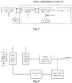
- Fig. 2 is a structure diagram showing a system for providing a constant power source according to an embodiment of the present application.
- the system 200 for providing a constant power source according to the embodiment of the present application may include a battery management system (not shown in Fig. 2 ), a high-voltage battery pack 10, a timer power supply module 20, a timer device 30 and a high-voltage power supply module 40, wherein the battery management system includes a main control module 50 and a power conversion module 60.
- the main control module 50 is configured to send a wake-up time that is received to the timer device 30;
- the timer power supply module 20 is configured to supply power to the timer device 30 according to electric energy in the high-voltage battery pack 10;
- the high-voltage power supply module 40 is configured to supply power to the power conversion module 60 according to the electric energy in the high-voltage battery pack 10;
- the timer device 30 is configured to set a wake-up clock according to the wake-up time, start timing when the battery management system enters into sleep, and send a discharge instruction to the high-voltage battery pack 10 when the timing reaches the wake-up time;
- the power conversion module 60 is configured to convert high-voltage electric energy, which is output by the high-voltage battery pack 10 according to the discharge instruction, into low-voltage electric energy, and use the low-voltage electric energy to power the battery management system.
- the wake-up time received by the main control module 50 is a wake-up time set by the vehicle control module.
- the vehicle control module may set the wake-up time and send the wake-up time to the timer device 30 via the main control module 50 of the battery management system.
- the main control module 50 may be, for example, a Micro-programmed Control Unit (Micro-programmed Control Unit, MCU).
- MCU Micro-programmed Control Unit
- the system for providing the constant power source may periodically wake up the BMS by the timer device, provide a power source for the BMS when the BMS is in sleep, and thus ensure normal operation of the BMS to monitor the status of the vehicle, which may not only reduce energy consumption of the BMS but also avoid the aging problem caused by a circuit control equipment supplying power in a long time and thus extend the life of the BMS.
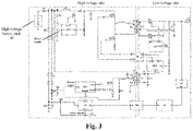
- Fig. 3 is a detailed structure diagram showing a system for providing a constant power source according to an exemplary embodiment of the present application. It should be noted that these embodiments are not intended to limit the scope of the present application.
- the power conversion module 60 includes a flyback power control module 601, a first high-voltage transmission module, a resonance control module 603, a synchronous rectifier module 604, a voltage-boost control module 605 and a second high-voltage transmission module.
- the timer device 30 is further configured to provide an enable signal to the flyback power control module 601 when the timing reaches the wake-up time, and under the control of the enable signal, the flyback power control module 601 starts to operate.
- the flyback power control module 601 is configured to provide a power source for the resonance control module 603 and the synchronous rectifier module 604 via the first high-voltage transmission module.
- the resonance control module 603 is configured to control conduction between the voltage-boost control module 605 and the second high-voltage transmission module when detecting that the second high-voltage transmission module outputs a low-voltage power signal.
- the voltage-boost control module 605 is configured to perform voltage-boost processing on electric energy provided by the high-voltage battery pack to obtain high-voltage direct-current electric energy.
- the second high-voltage transmission module is configured to convert the high-voltage direct-current electric energy into the low-voltage electric energy.
- the synchronous rectifier module 604 is configured to perform synchronous rectification processing on the low-voltage electric energy, and use the low-voltage electric energy after the synchronous rectification processing to supply power to the battery management system.
- the vehicle control module may be powered off after setting the wake-up time, generating a timing wake-up instruction according to the wake-up time, and issuing the wake-up instruction the BMS.
- the BMS issues the timing wake-up instruction to the timer device via the main control module. After the timer has set the wake-up time, the BMS will enter into sleep. When the timing of the timer device reaches the wake-up time, the timer device will issue a discharge command to the high-voltage battery pack.
- the electric energy in the high-voltage battery pack is converted into the low-voltage electric energy from high-voltage electric energy by the power conversion module to provide the power source for the BMS, so that the BMS is awakened from sleep and starts to monitor the SOC, voltage, current and other related information of the battery pack of the vehicle and handle it accordingly.
- the timer power supply module may include a clock power access point A, a first voltage-divider resistor network R1 and a first voltage-stabilizer unit DZ1, and the timer device 30 includes a clock power terminal VCC1.
- the clock power access point A is located at a positive electrode of the high-voltage battery pack.
- One terminal of the first voltage-divider resistor network R1 is connected to the clock power access point A, and the other terminal of the first voltage-divider resistor network R1 is connected to the clock power terminal VCC1.
- One terminal of the first voltage-stabilizer unit DZ1 is connected to the other terminal of the first voltage-divider resistor network R1, and the other terminal of the first voltage-stabilizer unit DZ1 is connected to a reference voltage terminal.
- the first voltage-divider resistor network R1 may include a plurality of resistors connected in series, and the first voltage-stabilizer unit DZ1 may include a voltage-stabilizer diode.
- the clock power access point A may provide a constant voltage V RTC to the timer device 30 via the first voltage-divider resistor network R1, and provide a stable operating voltage to the clock power terminal VCC1 of the timer device 30 through voltage-stabilizing by the first voltage-stabilizer unit DZ1.
- the constant voltage may also be provided to the timer device by a backup battery.
- the timer device according to the embodiments of the present application may maintain continuous operation by means of the constant voltage provided by the timer power supply module or the backup battery, and is not affected by sleeping and stopping operation of the BMS.
- the timer device 30 may include a real-time clock (Real Time Clock, RTC), the clock power terminal VCC1, a clock input terminal IN1 and a clock output terminal OUT1.
- RTC Real Time Clock
- the timer device 30 is further configured to receive the wake-up time via the clock input terminal IN1 and set the real-time clock RTC according to the wake-up time.
- the real-time clock RTC starts timing when the battery management system enters into sleep, and provides the enable signal via the clock output terminal when the timing reaches the wake-up time. That is, the clock output terminal OUT1 of the real-time clock enables an enable pin (Enable) of the flyback power control module 601.
- the high-voltage power supply module may include a flyback power supply module, a first high-voltage power supply access point C and a voltage-boost control power supply module.
- the flyback power supply module is configured to provide a startup voltage to the flyback power control module 601.
- the first high-voltage power supply access point C is configured to provide the electric energy in the high-voltage battery pack to the first high-voltage transmission module.
- the voltage-boost control power supply module is configured to supply power to the voltage-boost control module according to the electric energy in the high-voltage battery pack.
- the flyback power supply module may include a flyback control power access point B, a second voltage-divider resistor network R2 and a second voltage-stabilizer unit DZ2.
- the flyback control power access point B is located at the positive electrode of the high-voltage battery pack.
- One terminal of the second voltage-divider resistor network R2 is connected to the flyback control power access point B, and the other terminal of the second voltage-divider resistor network R2 is connected to a flyback power terminal VCC2 of the flyback power control module 601.
- One terminal of the second voltage-stabilizer unit DZ2 is connected to the other terminal of the second voltage-divider resistor network R2, and the other terminal of the second voltage-stabilizer unit DZ2 is connected to the reference voltage terminal.
- the flyback power control module 601 may receive the enable signal via the enable terminal "Enable”, and use the enable signal to enable the flyback power control module 601 to start to operate.
- the second voltage-divider resistor network R2 may include a plurality of resistors connected in series, and the second voltage-stabilizer unit DZ2 may include a voltage-stabilizer diode.
- the flyback control power access point B provides a constant voltage Vss to the flyback power control module 601 via the second voltage-divider resistor network R2.
- the flyback power terminal VCC2 of the flyback power control module 601 obtains a stable startup voltage.
- the voltage-boost control power supply module may include a second high-voltage power supply access point D and a third voltage-divider resistor network R3, and the third voltage-divider resistor network R3 may include a plurality of resistors connected in series.
- the second high-voltage power supply access point D is located at the positive electrode of the high voltage battery pack 10.
- One terminal of the third voltage-divider resistor network R3 is connected to the second high-voltage power supply access point D, and the other terminal of the third voltage-divider resistor network is connected to a voltage-boost control power terminal of the voltage-boost control module.
- the third voltage-divider resistor network R3 may function as a voltage divider. By adjusting the resistance value of the third voltage-divider resistor network R3, the variation range of the operating voltage of the voltage-boost control module may be adjusted to enable the voltage-boost control module to obtain a stable operating voltage.
- the first high-voltage transmission module includes a first switch device Q1 and a first transformer T1
- the flyback power control module 601 includes a flyback output terminal OUT2.
- the flyback power control module 601 is further configured to control turn-on and turn-off of the first switch device Q1 by a pulse width modulation signal output from the flyback output terminal OUT2.
- a first part Np1 of a primary winding of the first transformer T1 stores energy
- the first switch device Q1 is turned off the energy stored in the first part Np1 of the primary winding is coupled to a second part Np2 of the primary winding and a secondary winding Ns1 of the first transformer T1.
- the electric energy coupled to the secondary winding Ns1 of the first transformer T1 is used to provide the power source for the resonance control module 603 and the synchronous rectifier module 604, and the electric energy coupled to the second part Np2 of the primary winding of the first transformer T1 is used to provide electric energy for the flyback power control module 601.
- the power conversion module further includes a first rectifier and filter unit, which is connected to a resonance control power terminal VCC3 of the resonance control module 603 and a synchronous rectifier power terminal VCC4 of the synchronous rectifier module 604, respectively.
- the first rectifier and filter unit is configured to perform rectification and filter processing on the electric energy coupled to the secondary winding Ns1 of the first transformer T1, and input the electric energy after the rectification and filter processing to the resonance control power terminal VCC3 and the synchronous rectifier power terminal VCC4.
- the first rectifier and filter unit includes a first rectifier diode network D1 and a first filter capacitor network C1.
- An input terminal of the first rectifier diode network D1 is connected to a dotted terminal of the secondary winding of the first transformer T1
- an output terminal of the first rectifier diode network D1 is connected to one terminal of the first filter capacitor network C1
- the other terminal of the first filter capacitor network C1 is connected to an un-dotted terminal of the secondary winding of the first transformer T1 and the reference voltage terminal.
- the first rectifier diode network D1 may include a single diode device or two or more diodes connected in series and/or in parallel.
- the first filter capacitor network C1 may include a single capacitor or more than two capacitors connected a series and/or in parallel.
- the first rectifier diode network may function as a rectifier and improve current passing capacity, and the first filter capacitor network may function as a filter.
- the resonance control module 603 further includes a resonance control power terminal VCC3, a pair of resonance control output ports OUT3 and OUT4, and a low-voltage signal feedback pin FB 1.
- the system for providing the constant power source further includes a first isolator device 70, which includes a first pair of isolator input ports IN2 and IN3 and a first pair of isolator output ports OUT5 and OUT6.
- the second high-voltage transmission module may include a second transformer T2 and a second pair of switch devices Q2 and Q3.
- the resonance control power terminal VCC3 is connected to the output terminal of the first high-voltage transmission module
- the pair of resonance control output ports OUT3 and OUT4 is connected to the first pair of isolator input ports IN2 and IN3
- the first pair of isolator output ports OUT5 and OUT6 is connected to the second pair of switch devices Q2 and Q3
- the second pair of switch devices Q2 and Q3 is connected to the output terminal of the voltage-boost control module 605
- the low-voltage signal feedback pin FB1 is connected to the output terminal of the second high-voltage transmission module.
- the resonance control module 603 is configured to start to operate according to the power source provided by the first high-voltage transmission module, and when the low-voltage signal feedback pin FB1 detects that the second high-voltage transmission module outputs a low-voltage power signal, control turn-on of the second pair of switch devices Q2 and Q3 by the first isolator device 70.
- the second high-voltage transmission module is configured to convert the high-voltage direct-current electric energy after the voltage-boost processing by the voltage-boost control module 605 into the low-voltage electric energy when the second pair of switch devices Q2 and Q3 is turned on.
- the pair of resonance control output ports includes a first resonance control output terminal OUT3 and a second resonance control output terminal OUT4
- the first pair of isolator input ports includes a first isolator input terminal IN2 and a second isolator input terminal IN3
- the first pair of isolator output ports includes a first isolator output terminal OUT5 and a second isolator output terminal OUT6
- the second pair of switch devices includes a second switch device Q2 and a third switch device Q3.
- the first resonance control output terminal OUT3 is connected to the first isolator input terminal IN2, the second resonance control output terminal OUT4 is connected to the second isolator input terminal IN3, the first isolator output terminal OUT5 is connected to the second switch device Q2, and the second isolator output terminal OUT6 is connected to the third switch device Q3.
- the voltage-boost control module 605 includes a voltage-boost control power terminal VCC5, a voltage-boost control output terminal OUT9 and a high-voltage signal feedback pin FB2.
- the voltage-boost control module 605 is further configured to perform the voltage-boost processing on the electric energy provided by the high-voltage battery pack 10 to obtain the high-voltage direct-current electric energy when the high-voltage signal feedback pin FB2 detects the high-voltage power signal output by the high-voltage battery pack.
- the voltage-boost control power supply module includes a second high-voltage power supply access point D and a third voltage-divider resistor network R3.
- the second high-voltage power supply access point D is located at the positive electrode of the high-voltage battery pack 10
- one terminal of the third voltage-divider resistor network R3 is connected to the second high-voltage power supply access point D
- the other terminal of the third voltage-divider resistor network R3 is connected to the voltage-boost control power terminal VCC5.
- the synchronous rectifier module 604 includes a synchronous rectifier power terminal VCC4 and a pair of synchronous rectifier output ports OUT7 and OUT8, and the second high-voltage transmission module includes a third pair of switch devices Q4 and Q5.
- the synchronous rectifier power terminal 604 is connected to the output terminal of the first high-voltage transmission module, and the pair of synchronous rectifier output ports is connected to the third pair of switch devices.
- the synchronous rectifier module 604 is further configured to detect the low-voltage electric energy output by the second high-voltage transmission module, control turn-on of the third pair of switch devices when the low-voltage electric energy meets a low-voltage threshold condition, and use the low-voltage electric energy to supply power to the battery management system when the third pair of switch devices is turned on.
- the pair of synchronous rectifier output ports includes a first synchronous rectifier output terminal OUT7 and a second synchronous rectifier output terminal OUT8, and the third pair of switch devices includes a fourth switch device Q4 and a fifth switch device Q5.
- a control terminal of the fourth switch device Q4 is connected to the first synchronous rectifier output terminal OUT7, and a first load access terminal of the fourth switch device Q4 is connected to a first terminal of the secondary winding Ns2 of the second transformer T2. As shown in Fig. 3 , the first terminal of the secondary winding Ns2 of the second transformer T2 is an un-dotted terminal.
- a control terminal of the fifth switch device Q5 is connected to the second synchronous rectifier output terminal OUT8, and a first load access terminal of the fifth switch device Q5 is connected to a second terminal of the secondary winding of the second transformer T2.
- the second terminal of the secondary winding Ns2 of the second transformer T2 is a dotted terminal.
- a second load access terminal of the fifth switch device Q5 is connected to a second load access terminal of the fourth switch device Q4, and a center-tap output terminal of the second transformer T2 is connected to the reference voltage terminal.
- the power conversion module 60 further includes a second rectifier and filter unit, and the second rectifier and filter unit is connected to the output terminal of the second high-voltage transmission module.
- the second rectifier and filter unit is configured to perform rectification and filter processing on the low-voltage electric energy after the synchronous rectification processing, and send the low-voltage electric energy after the rectification and filter processing to the battery management system.
- the system for providing the constant power source further includes a second rectifier and filter unit, and the second rectifier and filter unit includes a second filter capacitor network C2.
- the second filter capacitor network may include a plurality of capacitors connected in parallel, and the plurality of capacitors connected in parallel may have different capacitance values.
- one terminal of the second filter capacitor network C2 is connected to the second load access terminal of the fifth switch device, and the other terminal of the second filter capacitor network C2 is connected to the reference voltage terminal.
- the second filter capacitor network C2 may function as a filter and a stabilizer.
- the first voltage-divider resistor network R1, the second voltage-divider resistor network R2 and the third voltage-divider resistor network R3 may each include a resistor.
- the first voltage-divider resistor network R1, the second voltage-divider resistor network R2 and the third voltage-divider resistor network R3 may each include more than two resistors connected in series and/or in parallel.
- the combination and resistance values of the first voltage-divider resistor network R1, the second voltage-divider resistor network R2 and the third voltage-divider resistor network R3 may be set according to actual situations.
- the system for providing the constant power source further includes a low-dropout linear regulator module 80 and a second isolator device 90.
- the low-dropout linear regulator module 80 is configured to perform voltage-reduction processing on the low-voltage electric energy to obtain the electric energy after the voltage-reduction processing.
- the main control module 50 is further configured to start to operate according to the electric energy after the voltage-reduction processing, and send the wake-up time to the timer device 30 via the second isolator device 90.
- the low-dropout linear regulator module performs the voltage-reduction processing on the low-voltage electric energy to obtain the operating voltage of the main control module and thus enable the main control module to start to operate.
- the low-dropout linear regulator module may stabilize the low-voltage electric energy output by the second high-voltage transmission module, so that the output low-voltage electric energy maintains a stable voltage.
- an anti-reverse diode network D3 may be included between the high-voltage battery pack 10 and the clock power access point A, the first high-voltage power supply access point C, the flyback control power access point B or the second high-voltage power supply access point D. That is to say, in the embodiments, the electric energy in the high-voltage battery pack is input to the clock power access point A, the flyback control power access point B, the first high-voltage power supply access point C or the second high-voltage power supply access point D through the anti-reverse diode network D3.
- the anti-reverse diode network D3 is connected to the positive electrode of the high-voltage battery pack.
- the anti-reverse diode network D3 may prevent the current in the high-voltage battery pack from passing through. At this time, the high-voltage battery pack and a load circuit connected to the high-voltage battery pack cannot form a loop, so that the load circuit connected to the high-voltage battery pack is protected from damage.
- the system for providing the constant power source may further include a first buffer circuit module, and the first buffer circuit module may include a first buffer diode network and a first buffer capacitor network.
- One terminal of the first buffer diode network is connected to the other terminal of the first voltage-divider resistor network R1 and the other terminal of the first buffer diode network is connected to the reference voltage terminal.
- One terminal of the first buffer capacitor network is connected to the other terminal of the first voltage-divider resistor network R1 and the other terminal of the first buffer capacitor network is connected to the reference voltage terminal.
- the first buffer circuit module may be configured to suppress voltage oscillation, thereby protecting the stability of the voltage provided by the high-voltage battery pack to the timer device.
- the system for providing the constant power source may further include a second buffer circuit module, and the second buffer circuit module may include a second buffer diode network and a second buffer capacitor network.
- One terminal of the second buffer diode network is connected to the other terminal of the second voltage-dividing resistor network R2 and the other terminal of the second buffer diode network is connected to the reference voltage terminal.
- One terminal of the second buffer capacitor network is connected to the other terminal of the second voltage-divider resistor network R2 and the other terminal of the second buffer capacitor network is connected to the reference voltage terminal.
- the first rectifier diode network, the first buffer diode network and the second buffer diode network may each include one diode.
- the first rectifier diode network, the first buffer diode network and the second buffer diode network may each include more than two diodes connected in series and/or in parallel.
- the combination of the first buffer diode network or the second buffer diode network may be set according to actual situations.
- the first filter capacitor network, the second filter capacitor network, the first buffer capacitor network and the second buffer capacitor network may each include one capacitor.
- the first filter capacitor network, the second filter capacitor network, the first buffer capacitor network and the second buffer capacitor network may each include more than two capacitors connected in series and/or in parallel.
- the combination of the first buffer capacitor network and the second buffer capacitor network may be set according to actual situations.
- the VCU when the vehicle needs to be powered off, the VCU is powered off after setting the wake-up time and sending the wake-up instruction to the BMS.
- the BMS issues the wake-up instruction to the timer device via the main control module.
- the timer sets the real-time clock according to the wake-up instruction and then the BMS enters into sleep. When the timer reaches the preset time, it will provide the enable signal to the enable terminal of the flyback power control module.
- the flyback power control module starts to operate and controls turn-on and turn-off of the switch device Q1, thereby controlling the primary side of the first transformer to store and release energy. That is, when Q1 is turned on, the first part Np1 of the primary winding of the first transformer stores energy; when Q1 is turned off, the energy is coupled to the second part Np2 of the first transformer and the secondary winding Ns1 of the first transformer.
- the output electric energy provides the power source for the resonance control module and the synchronous rectifier module, and then the resonance control module and the synchronous rectifier module start to operate.
- a feedback pin of the resonance control module detects a low voltage output from the low-voltage side, for example 24V, and controls the operation of Q2 and Q3 on the high-voltage side by the first isolator device.
- the electric energy in the Np2 of the first transformer is diode-rectified and then provides the power source for the flyback control module.
- the voltage-boost control module on the high-voltage side may perform the voltage-boost processing on the electric energy provided by the high-voltage battery pack.
- the second transformer When Q2 and Q3 are turned on, the second transformer outputs stable low-voltage (for example, 24V) electric energy at the low-voltage side based on the electric energy after the voltage-boost processing in the high-voltage battery pack.
- the low-voltage electric energy is stepped down by the low-dropout linear regulator module and then provides the electric energy to the main control module to enable the main control module to operate normally, so that the BMS operates normally and monitor, store and correspondingly handle data relevant to the battery.
- the system for providing the constant power source wakes up the BMS by the timer device when the BMS is in sleep and provides a stable power source for the BMS to ensure that the BMS is in the powered state and capable of collecting and storing the information relevant to the battery pack of the vehicle, realizing real-time monitoring of the vehicle by the BMS.
- the wake-up of the BMS is realized by the timer device without assistance of the lead-acid battery of the vehicle, thereby reducing the loss of lead-acid in the lead-acid battery and increasing the life of the lead-acid battery.
- the BMS When the electric vehicle is not used, the BMS may be put into sleep temporarily, and the wake-up time of the BMS may be set according to actual needs. This may not only reduce energy consumption of the BMS, but also avoid the aging problem caused by the circuit control equipment when powering for a long time and thus extend its life.
- Fig. 4 is a flowchart showing a method for providing a constant power source according to an embodiment of the present application.
- the method for providing a constant power source may be applied to the above-mentioned system for providing a constant power source described in conjunction with Figs. 1 to 3 .
- the system for providing the constant power source may include a battery management system, a high-voltage battery pack, a timer power supply module, a timer device and a high-voltage power supply module, wherein the battery management system includes a main control module and a power conversion module.
- the method 400 for providing a constant power source may include:
- the wake-up time received by the main control module in step S410 is the wake-up time set by the vehicle control module.
- the vehicle control module may set the wake-up time and send the wake-up time to the timer device via the main control module.
- the method 400 for providing a constant power source may further include: powering off the vehicle control module, and after the wake-up time is sent to the timer device via the main control module, powering off the battery management system.
- the method 400 for providing a constant power source may further include: after receiving, by the main control module, the wake-up time and sending the wake-up moment to the timer device, powering off the battery management system.
- the method 400 for providing a constant power source further includes: step S450, when the timing of the timer device does not reach the wake-up time and the vehicle control module is in operation, providing, by the vehicle control module, the operating voltage to the high-voltage battery pack to enable the high-voltage battery pack to start to operate.
- the method 400 for providing a constant power source further includes: step S460, when the timing of the timer device reaches the wake-up time and the vehicle control module is in sleep, resetting, by the timer device, the wake-up clock according to the wake-up time.
- the BMS wakes up from sleep, and when the vehicle control module is not operating, the timer continues to time. After the BMS is awakened from sleep, if the vehicle control module is still not operating, the BMS will enter into sleep after sending the wake-up instruction to the timer and wait for the next wake-up. Once the VCU is found to start operating, the sleep-awakened state ends.
- Fig. 5 illustrates a flowchart of a method for providing a constant power source according to another embodiment of the present application. As shown in Fig. 5 , in the embodiments, the method for providing a constant power source may include the steps as described below.
- step S501 the vehicle control module determines whether it needs to be powered off when operating normally.
- step S502 if it needs to be powered off, the vehicle control module is powered off after issuing the timing wake-up instruction to the BMS; if it does not need to be powered off, the VCU operates normally, and the method for providing a constant power source ends.
- the BMS sends the timing wake-up instruction to the timer device to enable the timer device to set the wake-up clock according to the wake-up time, and then the BMS is powered off and in sleep.
- step S504 when the timing of the timer device reaches the wake-up time that is predetermined, the power conversion module is enabled to operate by the timer device.
- the step of enabling the power conversion module to operate by the timer device may specifically include sending the enable signal to a forward power control module when the timer reaches the wake-up time.
- the forward power control module starts to operate; the forward power control module controls turn-on and turn-off of the switch device Q1, and thus controls the storage and release of the electric energy in the primary winding Np1 of the transformer T1.
- the forward power control module further controls turn-on and turn-off of the switch device Q2 and the switch device Q3.
- the switch device Q3 is turned on, the high-voltage electric energy output by the high-voltage battery pack is converted into the low-voltage electric energy by the transformer T2.
- step S505 the high-voltage electric energy output by the high-voltage battery pack is converted into the stable low-voltage electric energy by the power conversion module, and then the BMS operates normally.
- step S506 it is determined whether the vehicle control module operates normally. If the vehicle control module operates normally, the BMS will not enter into sleep after completing normal operation.
- step S507 if the vehicle control module does not operate normally, that is, the vehicle control module is still in sleep, then after the BMS completes the normal operation, the timer device resets the wake-up clock according to the wake-up time, and the BMS is powered off again and thus in sleep.
- the method for providing a constant power source wakes up the BMS by the timer device when the BMS is in sleep, and provide a stable power source for the BMS by the high-voltage battery pack to ensure that the BMS is in the powered state and capable of monitoring the status of the vehicle in real-time.
- the BMS is awakened without assistance of the vehicle lead-acid battery, thereby the loss of lead-acid in the lead-acid battery is reduced and the life of the lead-acid battery is increased.
- the processes described above with reference to the flowcharts may be implemented as a computer software program.
- the embodiments of the present application include a computer program product, which includes a computer program tangibly contained on a machine-readable medium, and the computer program includes program codes for implementing the methods shown in the flowcharts.
- the computer program may be downloaded and installed from a network, and/or installed from a removable storage medium.
- the above-mentioned embodiments may be implemented in whole or in part by software, hardware, firmware, or any combination thereof.
- the embodiments When implemented by software, the embodiments may be implemented in the form of a computer program product in whole or in part.
- the computer program product includes one or more computer instructions, which when executed on a computer, cause the computer to implement the methods described in the foregoing various embodiments.
- the computer program instructions When the computer program instructions are loaded and executed on the computer, all or part of the processes or functions described in the embodiments of the present application are generated.
- the computer may be a general-purpose computer, a dedicated computer, a computer network, or other programmable devices.
- the computer instructions may be stored in a computer-readable storage medium or transmitted from a computer-readable storage medium to another computer-readable storage medium.
- the computer instructions may be transmitted from a website, computer, server, or data center to another website, computer, server or data center via wired media (such as coaxial cable, optical fiber, digital subscriber line (DSL)) or wireless media (such as infrared, wireless, microwave, etc.).
- the computer-readable storage medium may be any available medium that can be accessed by the computer or a data storage device such as a server or data center integrated with one or more available media.
- the applicable media may be magnetic media (for example, a floppy disk, a hard disk, and a magnetic tape), optical media (for example, a DVD), or semiconductor media (for example, a solid state hard disk).
- the device embodiments described above are merely illustrative.
- the units described as separate components may or may not be physically separated, and the components displayed as units may or may not be physical units, that is, they may be located at a same place or may be distributed to multiple network units. Some or all of the modules may be selected according to actual needs to achieve the objectives of the embodiments. Those ordinary skill in the art may understand and implement the embodiments without creative work.
Description
- The present application relates the technical field of battery management, and in particular, to a system and method for providing a constant power source.
- At present, in face of energy shortage and increasingly serious environmental pollution, it is imperative to develop pure electric new energy vehicles. New energy vehicles will become an important way to reduce vehicle exhaust emissions, reduce energy consumptions and relieve environmental pressures. A Battery Management System (Battery Management System, BMS) is an important part of energy management for a new energy vehicle, and it may realize intelligent management and maintenance of a power battery system of an electric vehicle.
- Usually, a lead-acid battery of a vehicle may be used to provide a power source for the BMS. However, in a traditional power supply system, when the vehicle is not provided with the lead-acid battery and the BMS is in sleep, the BMS will stay in sleep and cannot be restarted, resulting in the BMS unable to monitor and handle status of a battery pack of the vehicle.
-
JP 5 439108 B2 - Embodiments of the present application provide a system and method for providing a constant power source, which may realize wake-up of a BMS when the BMS is in sleep and provide a stable power source for the BMS.
- According to an aspect of the embodiments of the present application, there is provided a system for providing a constant power source, comprising a vehicle control module, a battery management system, a high-voltage battery pack, a timer power supply module, a timer device and a high-voltage power supply module, wherein the battery management system comprises a main control module and a power conversion module, and wherein the main control module is configured to send a wake-up time that is received to the timer device, the timer power supply module is configured to supply power to the timer device according to electric energy in the high-voltage battery pack, the high-voltage power supply module is configured to supply power to the power conversion module according to the electric energy in the high-voltage battery pack, the timer device is configured to set a wake-up clock according to the wake-up time, start timing when the battery management system enters into sleep, and send a discharge instruction to the high-voltage battery pack when the timing reaches the wake-up time, and the power conversion module is configured to convert high-voltage electric energy, which is output by the high-voltage battery pack according to the discharging instruction, into low-voltage electric energy and use the low-voltage electric energy to supply power to the battery management system.
- According to another aspect of the embodiments of the present application, there is provided a method for providing a constant power source, comprising: receiving, by a main control module, a wake-up time and sending the wake-up time to a timer device; supplying, by a timer power supply module, power to the timer device according to electric energy in a high-voltage battery pack and supplying, by a high-voltage power supply module, power to a power conversion module according to the electric energy in the high-voltage battery pack; setting, by the timer device, a wake-up clock according to the wake-up time, starting timing when the battery management system enters into sleep, and sending a discharge instruction to the high-voltage battery pack when the timing reaches the wake-up time; converting, by the power-conversion module, high-voltage electric energy, which is output by the high-voltage battery pack according to the discharging instruction, into low-voltage electric energy and using the low-voltage electric energy to supply power to the battery management system.
- The system and method for providing a constant power source according to the aspects of the embodiments of the present application, wakes up the BMS by the timer device when the BMS is in sleep, and provides the stable power source for the BMS by the high-voltage battery pack to ensure that the BMS is in a powered state and facilitate the BMS collecting and storing information relevant to a battery pack of a vehicle, realizing wake-up of the BMS and monitoring of information on the status of the vehicle. It is unnecessary to rely on a lead-acid battery of the vehicle in the wake-up process, thereby reducing the loss of lead-acid in the lead-acid battery and increasing the life of the lead-acid battery.
- The present invention is set out by the features of the independent claims. Preferred embodiments are disclosed by the dependent claims.
- The drawings required to describe embodiments of the present application are introduced briefly below to illustrate technical solutions of the embodiments of the present application more clearly, and other drawings may be obtained by those ordinary skilled in the art from those drawings without any creative work.
-
Fig. 1 is a schematic diagram showing a system structure in which a vehicle lead-acid battery supplies power to a battery management system according to an embodiment of the present application; -
Fig. 2 is a structure diagram showing a system for providing a constant power source according to an embodiment of the present application; -
Fig. 3 is a detailed structure diagram showing a system for providing a constant power source according to an exemplary embodiment of the present application; -
Fig. 4 is a flowchart showing a method for providing a constant power source according to an embodiment of the present application; -
Fig. 5 is a flowchart showing a method for providing a constant power source according to another embodiment of the present application. - Features and exemplary embodiments of various aspects of the present application will be described in detail below. In order to make the purpose, technical solutions, and advantages of the present application clearer, the present application is described in detail below with reference to the accompanying drawings and embodiments. It should be understood that specific embodiments described herein are merely intended to describe the present application, and are not intended to limit the present application. For those skilled in the art, the present application may be practiced without some of the specific details. The following description of the embodiments is only to provide a better understanding of the present application by illustrating examples of the present application.
- It is to be noted that relational terms such as first, second and the like are used herein solely to distinguish one entity or operation from another entity or operation without necessarily requiring or implying any actual such relationship or order between such entities or operations. Moreover, the terms "include", "comprise" or any other variants thereof are intended to cover non-exclusive inclusion, so that a process, method, article or device including a series of elements not only includes those elements, but also includes those that are not explicitly listed or also include elements inherent to the process, method, article or equipment. In the case that there are no more limitations, an element defined by the phrase "including..." does not exclude the existence of other same elements in the process, method, article or equipment that includes the element.
-
Fig. 1 is a schematic diagram showing a system structure in which a vehicle lead-acid battery supplies power to a battery management system according to an embodiment. As shown inFig. 1 , the vehicle lead-acid battery 101 may supply power to thebattery management system 102. Thebattery management system 102 may include abattery management unit 1021, a direct current/direct current conversion (DC/DC)module 1022 and abattery pack 1023. The DC/DC module 1022 may perform DC voltage conversion, for example, convert a 24V system power source to a 12V system power source to supply power to an electrical equipment of a vehicle-mounted 12V system. - In a new energy vehicle, the vehicle lead-
acid battery 101 may provide a power source for thebattery management system 102, and may also be connected to a low-voltage control unit 1024 via a power supply bus to supply power to the low-voltage control unit 1024. Thebattery management system 102 may realize information interaction with a vehicle control module (Vehicle Control Unit, VCU) 103 via a CAN bus and upload information relevant to the State Of charge (State Of Charge, SOC), voltage, current and so on of thebattery pack 1023 to the vehicle control module. - When the new energy vehicle is not provided with the vehicle lead-acid battery and is parked for a long time without being used, the vehicle control module and the battery management system are powered off. Since there is no vehicle lead-acid battery providing the power source, the BMS is in sleep and cannot monitor the SOC, voltage, current and so on of the battery pack of the new energy vehicle and handle it accordingly.
- The embodiments of the present application provide a system and method for providing a constant power source to provide the power source for the battery management system, so that when the battery management system is in sleep, it is periodically awakened at a set time to ensure that the battery management system is in a powered state and facilitate the battery management system's collecting and storing information relevant to the battery pack of the vehicle. The system and method for providing the constant power source according to the embodiments of the present application may wake up the BMS without assistance of the vehicle lead-acid battery, thereby reducing the loss of lead-acid in the vehicle lead-acid battery and increasing the life of the vehicle lead-acid battery.
-
Fig. 2 is a structure diagram showing a system for providing a constant power source according to an embodiment of the present application. As shown inFIG. 2 , the system 200 for providing a constant power source according to the embodiment of the present application may include a battery management system (not shown inFig. 2 ), a high-voltage battery pack 10, a timerpower supply module 20, atimer device 30 and a high-voltagepower supply module 40, wherein the battery management system includes amain control module 50 and apower conversion module 60. - In the embodiments, the
main control module 50 is configured to send a wake-up time that is received to thetimer device 30; the timerpower supply module 20 is configured to supply power to thetimer device 30 according to electric energy in the high-voltage battery pack 10; the high-voltagepower supply module 40 is configured to supply power to thepower conversion module 60 according to the electric energy in the high-voltage battery pack 10; thetimer device 30 is configured to set a wake-up clock according to the wake-up time, start timing when the battery management system enters into sleep, and send a discharge instruction to the high-voltage battery pack 10 when the timing reaches the wake-up time; and thepower conversion module 60 is configured to convert high-voltage electric energy, which is output by the high-voltage battery pack 10 according to the discharge instruction, into low-voltage electric energy, and use the low-voltage electric energy to power the battery management system. - In the embodiments, the wake-up time received by the
main control module 50 is a wake-up time set by the vehicle control module. The vehicle control module may set the wake-up time and send the wake-up time to thetimer device 30 via themain control module 50 of the battery management system. As an example, themain control module 50 may be, for example, a Micro-programmed Control Unit (Micro-programmed Control Unit, MCU). - The system for providing the constant power source according to the embodiments of the present application may periodically wake up the BMS by the timer device, provide a power source for the BMS when the BMS is in sleep, and thus ensure normal operation of the BMS to monitor the status of the vehicle, which may not only reduce energy consumption of the BMS but also avoid the aging problem caused by a circuit control equipment supplying power in a long time and thus extend the life of the BMS.
-
Fig. 3 is a detailed structure diagram showing a system for providing a constant power source according to an exemplary embodiment of the present application. It should be noted that these embodiments are not intended to limit the scope of the present application. - As shown in
Fig. 3 , in an embodiment, thepower conversion module 60 includes a flyback power control module 601, a first high-voltage transmission module, a resonance control module 603, a synchronous rectifier module 604, a voltage-boost control module 605 and a second high-voltage transmission module. - The
timer device 30 is further configured to provide an enable signal to the flyback power control module 601 when the timing reaches the wake-up time, and under the control of the enable signal, the flyback power control module 601 starts to operate. - The flyback power control module 601 is configured to provide a power source for the resonance control module 603 and the synchronous rectifier module 604 via the first high-voltage transmission module.
- The resonance control module 603 is configured to control conduction between the voltage-boost control module 605 and the second high-voltage transmission module when detecting that the second high-voltage transmission module outputs a low-voltage power signal.
- The voltage-boost control module 605 is configured to perform voltage-boost processing on electric energy provided by the high-voltage battery pack to obtain high-voltage direct-current electric energy.
- The second high-voltage transmission module is configured to convert the high-voltage direct-current electric energy into the low-voltage electric energy.
- The synchronous rectifier module 604 is configured to perform synchronous rectification processing on the low-voltage electric energy, and use the low-voltage electric energy after the synchronous rectification processing to supply power to the battery management system.
- In the embodiments of the present application, when the vehicle needs to be powered off, the vehicle control module may be powered off after setting the wake-up time, generating a timing wake-up instruction according to the wake-up time, and issuing the wake-up instruction the BMS. The BMS issues the timing wake-up instruction to the timer device via the main control module. After the timer has set the wake-up time, the BMS will enter into sleep. When the timing of the timer device reaches the wake-up time, the timer device will issue a discharge command to the high-voltage battery pack. The electric energy in the high-voltage battery pack is converted into the low-voltage electric energy from high-voltage electric energy by the power conversion module to provide the power source for the BMS, so that the BMS is awakened from sleep and starts to monitor the SOC, voltage, current and other related information of the battery pack of the vehicle and handle it accordingly.
- As shown in
Fig. 3 , in the embodiments, the timer power supply module may include a clock power access point A, a first voltage-divider resistor network R1 and a first voltage-stabilizer unit DZ1, and thetimer device 30 includes a clock power terminal VCC1. - In the embodiments, the clock power access point A is located at a positive electrode of the high-voltage battery pack. One terminal of the first voltage-divider resistor network R1 is connected to the clock power access point A, and the other terminal of the first voltage-divider resistor network R1 is connected to the clock power terminal VCC1. One terminal of the first voltage-stabilizer unit DZ1 is connected to the other terminal of the first voltage-divider resistor network R1, and the other terminal of the first voltage-stabilizer unit DZ1 is connected to a reference voltage terminal.
- In the embodiments, the first voltage-divider resistor network R1 may include a plurality of resistors connected in series, and the first voltage-stabilizer unit DZ1 may include a voltage-stabilizer diode.
- In the embodiments, the clock power access point A may provide a constant voltage VRTC to the
timer device 30 via the first voltage-divider resistor network R1, and provide a stable operating voltage to the clock power terminal VCC1 of thetimer device 30 through voltage-stabilizing by the first voltage-stabilizer unit DZ1. - In the embodiments, the constant voltage may also be provided to the timer device by a backup battery. The timer device according to the embodiments of the present application may maintain continuous operation by means of the constant voltage provided by the timer power supply module or the backup battery, and is not affected by sleeping and stopping operation of the BMS.
- Continuing to refer to
Fig.3 , in the embodiments, thetimer device 30 may include a real-time clock (Real Time Clock, RTC), the clock power terminal VCC1, a clock input terminal IN1 and a clock output terminal OUT1. - The
timer device 30 is further configured to receive the wake-up time via the clock input terminal IN1 and set the real-time clock RTC according to the wake-up time. - In this example, the real-time clock RTC starts timing when the battery management system enters into sleep, and provides the enable signal via the clock output terminal when the timing reaches the wake-up time. That is, the clock output terminal OUT1 of the real-time clock enables an enable pin (Enable) of the flyback power control module 601.
- As shown in
Fig. 3 , in the embodiments, the high-voltage power supply module may include a flyback power supply module, a first high-voltage power supply access point C and a voltage-boost control power supply module. - The flyback power supply module is configured to provide a startup voltage to the flyback power control module 601.
- The first high-voltage power supply access point C is configured to provide the electric energy in the high-voltage battery pack to the first high-voltage transmission module.
- The voltage-boost control power supply module is configured to supply power to the voltage-boost control module according to the electric energy in the high-voltage battery pack.
- Continuing to refer to
Fig. 3 , the flyback power supply module may include a flyback control power access point B, a second voltage-divider resistor network R2 and a second voltage-stabilizer unit DZ2. - The flyback control power access point B is located at the positive electrode of the high-voltage battery pack. One terminal of the second voltage-divider resistor network R2 is connected to the flyback control power access point B, and the other terminal of the second voltage-divider resistor network R2 is connected to a flyback power terminal VCC2 of the flyback power control module 601. One terminal of the second voltage-stabilizer unit DZ2 is connected to the other terminal of the second voltage-divider resistor network R2, and the other terminal of the second voltage-stabilizer unit DZ2 is connected to the reference voltage terminal.
- In the embodiments, the flyback power control module 601 may receive the enable signal via the enable terminal "Enable", and use the enable signal to enable the flyback power control module 601 to start to operate.
- In the embodiments, the second voltage-divider resistor network R2 may include a plurality of resistors connected in series, and the second voltage-stabilizer unit DZ2 may include a voltage-stabilizer diode.
- In the embodiments, the flyback control power access point B provides a constant voltage Vss to the flyback power control module 601 via the second voltage-divider resistor network R2. Through voltage stabilizing by the second voltage-stabilizer unit DZ2, the flyback power terminal VCC2 of the flyback power control module 601 obtains a stable startup voltage.
- Continuing to refer to
Fig. 3 , the voltage-boost control power supply module may include a second high-voltage power supply access point D and a third voltage-divider resistor network R3, and the third voltage-divider resistor network R3 may include a plurality of resistors connected in series. - The second high-voltage power supply access point D is located at the positive electrode of the high
voltage battery pack 10. One terminal of the third voltage-divider resistor network R3 is connected to the second high-voltage power supply access point D, and the other terminal of the third voltage-divider resistor network is connected to a voltage-boost control power terminal of the voltage-boost control module. - In the embodiments, the third voltage-divider resistor network R3 may function as a voltage divider. By adjusting the resistance value of the third voltage-divider resistor network R3, the variation range of the operating voltage of the voltage-boost control module may be adjusted to enable the voltage-boost control module to obtain a stable operating voltage.
- As shown in
Fig. 3 , in the embodiments, the first high-voltage transmission module includes a first switch device Q1 and a first transformer T1, and the flyback power control module 601 includes a flyback output terminal OUT2. - In the embodiments, the flyback power control module 601 is further configured to control turn-on and turn-off of the first switch device Q1 by a pulse width modulation signal output from the flyback output terminal OUT2.
- When the first switch device Q1 is turned on, a first part Np1 of a primary winding of the first transformer T1 stores energy, and when the first switch device Q1 is turned off, the energy stored in the first part Np1 of the primary winding is coupled to a second part Np2 of the primary winding and a secondary winding Ns1 of the first transformer T1.
- In the embodiments, the electric energy coupled to the secondary winding Ns1 of the first transformer T1 is used to provide the power source for the resonance control module 603 and the synchronous rectifier module 604, and the electric energy coupled to the second part Np2 of the primary winding of the first transformer T1 is used to provide electric energy for the flyback power control module 601.
- In the embodiments, the power conversion module further includes a first rectifier and filter unit, which is connected to a resonance control power terminal VCC3 of the resonance control module 603 and a synchronous rectifier power terminal VCC4 of the synchronous rectifier module 604, respectively.
- The first rectifier and filter unit is configured to perform rectification and filter processing on the electric energy coupled to the secondary winding Ns1 of the first transformer T1, and input the electric energy after the rectification and filter processing to the resonance control power terminal VCC3 and the synchronous rectifier power terminal VCC4.
- As shown in
Fig. 3 , in the embodiments, the first rectifier and filter unit includes a first rectifier diode network D1 and a first filter capacitor network C1. - An input terminal of the first rectifier diode network D1 is connected to a dotted terminal of the secondary winding of the first transformer T1, an output terminal of the first rectifier diode network D1 is connected to one terminal of the first filter capacitor network C1, and the other terminal of the first filter capacitor network C1 is connected to an un-dotted terminal of the secondary winding of the first transformer T1 and the reference voltage terminal.
- In the embodiments, the first rectifier diode network D1 may include a single diode device or two or more diodes connected in series and/or in parallel. The first filter capacitor network C1 may include a single capacitor or more than two capacitors connected a series and/or in parallel. The first rectifier diode network may function as a rectifier and improve current passing capacity, and the first filter capacitor network may function as a filter.
- As shown in
Fig. 3 , in the embodiments, the resonance control module 603 further includes a resonance control power terminal VCC3, a pair of resonance control output ports OUT3 and OUT4, and a low-voltage signal feedback pin FB 1. - The system for providing the constant power source further includes a first isolator device 70, which includes a first pair of isolator input ports IN2 and IN3 and a first pair of isolator output ports OUT5 and OUT6.
- Continuing to refer to
Fig. 3 , the second high-voltage transmission module may include a second transformer T2 and a second pair of switch devices Q2 and Q3. - The resonance control power terminal VCC3 is connected to the output terminal of the first high-voltage transmission module, the pair of resonance control output ports OUT3 and OUT4 is connected to the first pair of isolator input ports IN2 and IN3, the first pair of isolator output ports OUT5 and OUT6 is connected to the second pair of switch devices Q2 and Q3, the second pair of switch devices Q2 and Q3 is connected to the output terminal of the voltage-boost control module 605, and the low-voltage signal feedback pin FB1 is connected to the output terminal of the second high-voltage transmission module.
- The resonance control module 603 is configured to start to operate according to the power source provided by the first high-voltage transmission module, and when the low-voltage signal feedback pin FB1 detects that the second high-voltage transmission module outputs a low-voltage power signal, control turn-on of the second pair of switch devices Q2 and Q3 by the first isolator device 70.
- The second high-voltage transmission module is configured to convert the high-voltage direct-current electric energy after the voltage-boost processing by the voltage-boost control module 605 into the low-voltage electric energy when the second pair of switch devices Q2 and Q3 is turned on.
- In the embodiments, the pair of resonance control output ports includes a first resonance control output terminal OUT3 and a second resonance control output terminal OUT4, the first pair of isolator input ports includes a first isolator input terminal IN2 and a second isolator input terminal IN3, the first pair of isolator output ports includes a first isolator output terminal OUT5 and a second isolator output terminal OUT6, and the second pair of switch devices includes a second switch device Q2 and a third switch device Q3.
- The first resonance control output terminal OUT3 is connected to the first isolator input terminal IN2, the second resonance control output terminal OUT4 is connected to the second isolator input terminal IN3, the first isolator output terminal OUT5 is connected to the second switch device Q2, and the second isolator output terminal OUT6 is connected to the third switch device Q3.
- In the embodiments, the voltage-boost control module 605 includes a voltage-boost control power terminal VCC5, a voltage-boost control output terminal OUT9 and a high-voltage signal feedback pin FB2.
- The voltage-boost control module 605 is further configured to perform the voltage-boost processing on the electric energy provided by the high-
voltage battery pack 10 to obtain the high-voltage direct-current electric energy when the high-voltage signal feedback pin FB2 detects the high-voltage power signal output by the high-voltage battery pack. - In the embodiments, the voltage-boost control power supply module includes a second high-voltage power supply access point D and a third voltage-divider resistor network R3.
- The second high-voltage power supply access point D is located at the positive electrode of the high-
voltage battery pack 10, one terminal of the third voltage-divider resistor network R3 is connected to the second high-voltage power supply access point D, and the other terminal of the third voltage-divider resistor network R3 is connected to the voltage-boost control power terminal VCC5. - In the embodiments, the synchronous rectifier module 604 includes a synchronous rectifier power terminal VCC4 and a pair of synchronous rectifier output ports OUT7 and OUT8, and the second high-voltage transmission module includes a third pair of switch devices Q4 and Q5.
- The synchronous rectifier power terminal 604 is connected to the output terminal of the first high-voltage transmission module, and the pair of synchronous rectifier output ports is connected to the third pair of switch devices.
- The synchronous rectifier module 604 is further configured to detect the low-voltage electric energy output by the second high-voltage transmission module, control turn-on of the third pair of switch devices when the low-voltage electric energy meets a low-voltage threshold condition, and use the low-voltage electric energy to supply power to the battery management system when the third pair of switch devices is turned on.
- In the embodiments, the pair of synchronous rectifier output ports includes a first synchronous rectifier output terminal OUT7 and a second synchronous rectifier output terminal OUT8, and the third pair of switch devices includes a fourth switch device Q4 and a fifth switch device Q5.
- A control terminal of the fourth switch device Q4 is connected to the first synchronous rectifier output terminal OUT7, and a first load access terminal of the fourth switch device Q4 is connected to a first terminal of the secondary winding Ns2 of the second transformer T2. As shown in
Fig. 3 , the first terminal of the secondary winding Ns2 of the second transformer T2 is an un-dotted terminal. - A control terminal of the fifth switch device Q5 is connected to the second synchronous rectifier output terminal OUT8, and a first load access terminal of the fifth switch device Q5 is connected to a second terminal of the secondary winding of the second transformer T2. As shown in
Fig. 3 , the second terminal of the secondary winding Ns2 of the second transformer T2 is a dotted terminal. - A second load access terminal of the fifth switch device Q5 is connected to a second load access terminal of the fourth switch device Q4, and a center-tap output terminal of the second transformer T2 is connected to the reference voltage terminal.
- In the embodiments, the
power conversion module 60 further includes a second rectifier and filter unit, and the second rectifier and filter unit is connected to the output terminal of the second high-voltage transmission module. - The second rectifier and filter unit is configured to perform rectification and filter processing on the low-voltage electric energy after the synchronous rectification processing, and send the low-voltage electric energy after the rectification and filter processing to the battery management system.
- In the embodiments, the system for providing the constant power source further includes a second rectifier and filter unit, and the second rectifier and filter unit includes a second filter capacitor network C2. The second filter capacitor network may include a plurality of capacitors connected in parallel, and the plurality of capacitors connected in parallel may have different capacitance values.
- As shown in
Fig. 3 , one terminal of the second filter capacitor network C2 is connected to the second load access terminal of the fifth switch device, and the other terminal of the second filter capacitor network C2 is connected to the reference voltage terminal. In the embodiments, the second filter capacitor network C2 may function as a filter and a stabilizer. - Exemplarily, in the system for providing the constant power source shown in
Fig. 3 , the first voltage-divider resistor network R1, the second voltage-divider resistor network R2 and the third voltage-divider resistor network R3 may each include a resistor. In other embodiments, the first voltage-divider resistor network R1, the second voltage-divider resistor network R2 and the third voltage-divider resistor network R3 may each include more than two resistors connected in series and/or in parallel. - It should be noted that in actual application scenarios of the system for providing the constant power source, the combination and resistance values of the first voltage-divider resistor network R1, the second voltage-divider resistor network R2 and the third voltage-divider resistor network R3 may be set according to actual situations.
- In the embodiments, the system for providing the constant power source further includes a low-dropout linear regulator module 80 and a second isolator device 90.
- The low-dropout linear regulator module 80 is configured to perform voltage-reduction processing on the low-voltage electric energy to obtain the electric energy after the voltage-reduction processing.
- The
main control module 50 is further configured to start to operate according to the electric energy after the voltage-reduction processing, and send the wake-up time to thetimer device 30 via the second isolator device 90. - In the embodiments, the low-dropout linear regulator module performs the voltage-reduction processing on the low-voltage electric energy to obtain the operating voltage of the main control module and thus enable the main control module to start to operate. The low-dropout linear regulator module may stabilize the low-voltage electric energy output by the second high-voltage transmission module, so that the output low-voltage electric energy maintains a stable voltage.
- As shown in
Fig. 3 , in the embodiments, an anti-reverse diode network D3 may be included between the high-voltage battery pack 10 and the clock power access point A, the first high-voltage power supply access point C, the flyback control power access point B or the second high-voltage power supply access point D. That is to say, in the embodiments, the electric energy in the high-voltage battery pack is input to the clock power access point A, the flyback control power access point B, the first high-voltage power supply access point C or the second high-voltage power supply access point D through the anti-reverse diode network D3. - In the embodiments, the anti-reverse diode network D3 is connected to the positive electrode of the high-voltage battery pack. When the positive and negative electrodes of the high-voltage battery pack are connected reversely, as can be known from unidirectional conductivity of diodes, the anti-reverse diode network D3 may prevent the current in the high-voltage battery pack from passing through. At this time, the high-voltage battery pack and a load circuit connected to the high-voltage battery pack cannot form a loop, so that the load circuit connected to the high-voltage battery pack is protected from damage.
- In the embodiments, the system for providing the constant power source may further include a first buffer circuit module, and the first buffer circuit module may include a first buffer diode network and a first buffer capacitor network. One terminal of the first buffer diode network is connected to the other terminal of the first voltage-divider resistor network R1 and the other terminal of the first buffer diode network is connected to the reference voltage terminal. One terminal of the first buffer capacitor network is connected to the other terminal of the first voltage-divider resistor network R1 and the other terminal of the first buffer capacitor network is connected to the reference voltage terminal.
- In the embodiments of the present application, the first buffer circuit module may be configured to suppress voltage oscillation, thereby protecting the stability of the voltage provided by the high-voltage battery pack to the timer device.
- In the embodiments, the system for providing the constant power source may further include a second buffer circuit module, and the second buffer circuit module may include a second buffer diode network and a second buffer capacitor network. One terminal of the second buffer diode network is connected to the other terminal of the second voltage-dividing resistor network R2 and the other terminal of the second buffer diode network is connected to the reference voltage terminal. One terminal of the second buffer capacitor network is connected to the other terminal of the second voltage-divider resistor network R2 and the other terminal of the second buffer capacitor network is connected to the reference voltage terminal.
- In the system for providing the constant power source shown in
Fig. 3 , the first rectifier diode network, the first buffer diode network and the second buffer diode network may each include one diode. In other embodiments, the first rectifier diode network, the first buffer diode network and the second buffer diode network may each include more than two diodes connected in series and/or in parallel. In the actual application scenarios of the system for providing the constant power source, the combination of the first buffer diode network or the second buffer diode network may be set according to actual situations. - In the system for providing the constant power source shown in
Fig. 3 , the first filter capacitor network, the second filter capacitor network, the first buffer capacitor network and the second buffer capacitor network may each include one capacitor. In other embodiments, the first filter capacitor network, the second filter capacitor network, the first buffer capacitor network and the second buffer capacitor network may each include more than two capacitors connected in series and/or in parallel. - It should be noted that in the actual application scenarios of the system for providing the constant power source, the combination of the first buffer capacitor network and the second buffer capacitor network may be set according to actual situations.
- In the embodiments of the present application, when the vehicle needs to be powered off, the VCU is powered off after setting the wake-up time and sending the wake-up instruction to the BMS. The BMS issues the wake-up instruction to the timer device via the main control module. The timer sets the real-time clock according to the wake-up instruction and then the BMS enters into sleep. When the timer reaches the preset time, it will provide the enable signal to the enable terminal of the flyback power control module.
- Due to the existence of the enable signal, the flyback power control module starts to operate and controls turn-on and turn-off of the switch device Q1, thereby controlling the primary side of the first transformer to store and release energy. That is, when Q1 is turned on, the first part Np1 of the primary winding of the first transformer stores energy; when Q1 is turned off, the energy is coupled to the second part Np2 of the first transformer and the secondary winding Ns1 of the first transformer.
- After the electric energy in the secondary winding Ns1 of the first transformer is diode-rectified and capacitor-filtered, the output electric energy provides the power source for the resonance control module and the synchronous rectifier module, and then the resonance control module and the synchronous rectifier module start to operate. A feedback pin of the resonance control module detects a low voltage output from the low-voltage side, for example 24V, and controls the operation of Q2 and Q3 on the high-voltage side by the first isolator device. The electric energy in the Np2 of the first transformer is diode-rectified and then provides the power source for the flyback control module.
- The voltage-boost control module on the high-voltage side may perform the voltage-boost processing on the electric energy provided by the high-voltage battery pack. When Q2 and Q3 are turned on, the second transformer outputs stable low-voltage (for example, 24V) electric energy at the low-voltage side based on the electric energy after the voltage-boost processing in the high-voltage battery pack. The low-voltage electric energy is stepped down by the low-dropout linear regulator module and then provides the electric energy to the main control module to enable the main control module to operate normally, so that the BMS operates normally and monitor, store and correspondingly handle data relevant to the battery.
- If a vehicle is not provided with a lead-acid battery, the system for providing the constant power source according to the embodiments of the present application wakes up the BMS by the timer device when the BMS is in sleep and provides a stable power source for the BMS to ensure that the BMS is in the powered state and capable of collecting and storing the information relevant to the battery pack of the vehicle, realizing real-time monitoring of the vehicle by the BMS. In the embodiments of the present application, the wake-up of the BMS is realized by the timer device without assistance of the lead-acid battery of the vehicle, thereby reducing the loss of lead-acid in the lead-acid battery and increasing the life of the lead-acid battery.
- When the electric vehicle is not used, the BMS may be put into sleep temporarily, and the wake-up time of the BMS may be set according to actual needs. This may not only reduce energy consumption of the BMS, but also avoid the aging problem caused by the circuit control equipment when powering for a long time and thus extend its life.
-
Fig. 4 is a flowchart showing a method for providing a constant power source according to an embodiment of the present application. As shown inFig. 4 , in the embodiments, the method for providing a constant power source may be applied to the above-mentioned system for providing a constant power source described in conjunction withFigs. 1 to 3 . The system for providing the constant power source may include a battery management system, a high-voltage battery pack, a timer power supply module, a timer device and a high-voltage power supply module, wherein the battery management system includes a main control module and a power conversion module. In the embodiments, the method 400 for providing a constant power source may include: - step S410, receiving, by the main control module, the wake-up time and sending the wake-up time to the timer device;
- step S420, supplying, by the timer power supply module, power to the timer device according to the electric energy in the high-voltage battery pack, and by the high-voltage power supply module, supplying power to the power conversion module according to the electric energy in the high-voltage battery pack;
- step S430, setting, by the timer device, the wake-up clock according to the wake-up time, starting timing when the battery management system enters into sleep, and sending the discharge instruction to the high-voltage battery pack when the timing reaches the wake-up time; and
- step S440, converting, by the power conversion module, the high-voltage electric energy, which is output by the high-voltage battery pack according to the discharge instruction, into the low-voltage electric energy, and using the low-voltage electric energy to supply power to the battery management system.
- In the embodiments, the wake-up time received by the main control module in step S410 is the wake-up time set by the vehicle control module. In the embodiment, the vehicle control module may set the wake-up time and send the wake-up time to the timer device via the main control module.
- In the embodiments, after the step of setting, by the vehicle control module, the wake-up time and sending the wake-up time to the timer device via the main control module, the method 400 for providing a constant power source may further include:
powering off the vehicle control module, and after the wake-up time is sent to the timer device via the main control module, powering off the battery management system. - In the embodiments, the method 400 for providing a constant power source may further include: after receiving, by the main control module, the wake-up time and sending the wake-up moment to the timer device, powering off the battery management system.
- In the embodiments, the method 400 for providing a constant power source further includes:
step S450, when the timing of the timer device does not reach the wake-up time and the vehicle control module is in operation, providing, by the vehicle control module, the operating voltage to the high-voltage battery pack to enable the high-voltage battery pack to start to operate. - In the embodiments, the method 400 for providing a constant power source further includes:
step S460, when the timing of the timer device reaches the wake-up time and the vehicle control module is in sleep, resetting, by the timer device, the wake-up clock according to the wake-up time. - In the embodiments of the present application, during the period when the timer times, when the vehicle control module starts to operate, the BMS wakes up from sleep, and when the vehicle control module is not operating, the timer continues to time. After the BMS is awakened from sleep, if the vehicle control module is still not operating, the BMS will enter into sleep after sending the wake-up instruction to the timer and wait for the next wake-up. Once the VCU is found to start operating, the sleep-awakened state ends.
-
Fig. 5 illustrates a flowchart of a method for providing a constant power source according to another embodiment of the present application. As shown inFig. 5 , in the embodiments, the method for providing a constant power source may include the steps as described below. - As shown in step S501, the vehicle control module determines whether it needs to be powered off when operating normally.
- As shown in step S502, if it needs to be powered off, the vehicle control module is powered off after issuing the timing wake-up instruction to the BMS; if it does not need to be powered off, the VCU operates normally, and the method for providing a constant power source ends.
- As shown in step S503, the BMS sends the timing wake-up instruction to the timer device to enable the timer device to set the wake-up clock according to the wake-up time, and then the BMS is powered off and in sleep.
- As shown in step S504, when the timing of the timer device reaches the wake-up time that is predetermined, the power conversion module is enabled to operate by the timer device.
- In this step, the step of enabling the power conversion module to operate by the timer device may specifically include sending the enable signal to a forward power control module when the timer reaches the wake-up time. Under control of the enable signal, the forward power control module starts to operate; the forward power control module controls turn-on and turn-off of the switch device Q1, and thus controls the storage and release of the electric energy in the primary winding Np1 of the transformer T1. The forward power control module further controls turn-on and turn-off of the switch device Q2 and the switch device Q3. When the switch device Q3 is turned on, the high-voltage electric energy output by the high-voltage battery pack is converted into the low-voltage electric energy by the transformer T2.
- As shown in step S505, the high-voltage electric energy output by the high-voltage battery pack is converted into the stable low-voltage electric energy by the power conversion module, and then the BMS operates normally.
- As shown in step S506, it is determined whether the vehicle control module operates normally. If the vehicle control module operates normally, the BMS will not enter into sleep after completing normal operation.
- As shown in step S507, if the vehicle control module does not operate normally, that is, the vehicle control module is still in sleep, then after the BMS completes the normal operation, the timer device resets the wake-up clock according to the wake-up time, and the BMS is powered off again and thus in sleep.
- The method for providing a constant power source according to the embodiments of the present application, wakes up the BMS by the timer device when the BMS is in sleep, and provide a stable power source for the BMS by the high-voltage battery pack to ensure that the BMS is in the powered state and capable of monitoring the status of the vehicle in real-time. The BMS is awakened without assistance of the vehicle lead-acid battery, thereby the loss of lead-acid in the lead-acid battery is reduced and the life of the lead-acid battery is increased.
- It should be clear that the present application is not limited to the specific configuration and processing described in the above embodiments and shown in the drawings. For the convenience and brevity of description, detailed description of known methods are omitted herein, and reference may be made to the specific operating processes of the aforementioned systems, modules and units for corresponding processes in the method embodiments described above, which will not be repeated here.
- According to the embodiments of the present application, the processes described above with reference to the flowcharts may be implemented as a computer software program. For example, the embodiments of the present application include a computer program product, which includes a computer program tangibly contained on a machine-readable medium, and the computer program includes program codes for implementing the methods shown in the flowcharts. In such embodiments, the computer program may be downloaded and installed from a network, and/or installed from a removable storage medium.
- The above-mentioned embodiments may be implemented in whole or in part by software, hardware, firmware, or any combination thereof. When implemented by software, the embodiments may be implemented in the form of a computer program product in whole or in part. The computer program product includes one or more computer instructions, which when executed on a computer, cause the computer to implement the methods described in the foregoing various embodiments. When the computer program instructions are loaded and executed on the computer, all or part of the processes or functions described in the embodiments of the present application are generated. The computer may be a general-purpose computer, a dedicated computer, a computer network, or other programmable devices. The computer instructions may be stored in a computer-readable storage medium or transmitted from a computer-readable storage medium to another computer-readable storage medium. For example, the computer instructions may be transmitted from a website, computer, server, or data center to another website, computer, server or data center via wired media (such as coaxial cable, optical fiber, digital subscriber line (DSL)) or wireless media (such as infrared, wireless, microwave, etc.). The computer-readable storage medium may be any available medium that can be accessed by the computer or a data storage device such as a server or data center integrated with one or more available media. The applicable media may be magnetic media (for example, a floppy disk, a hard disk, and a magnetic tape), optical media (for example, a DVD), or semiconductor media (for example, a solid state hard disk).
- The device embodiments described above are merely illustrative. The units described as separate components may or may not be physically separated, and the components displayed as units may or may not be physical units, that is, they may be located at a same place or may be distributed to multiple network units. Some or all of the modules may be selected according to actual needs to achieve the objectives of the embodiments. Those ordinary skill in the art may understand and implement the embodiments without creative work.
- Finally, it should be noted that the above embodiments are merely used to illustrate rather than limit the technical solutions of the present application. Although the present application is described in detail with reference to the foregoing embodiments, those ordinary skill in the art should understand that it is still possible to modify the technical solutions described in the foregoing embodiments, or equivalently replace some or all of the technical features, and these modifications or replacements do not cause the essence of corresponding technical solutions to deviate from the ranges of the technical solutions of various embodiments of the present application.
Claims (15)
- A system (200) for providing a constant power source, which is applicable to an electric vehicle, the system comprising a battery management system, a high-voltage battery pack (10), a timer power supply module (20), a timer device (30) and a high-voltage power supply module (40), wherein the battery management system comprises a main control module (50) and a power conversion module (60), and whereinthe main control module is configured to receive a wake-up time and send the wake-up time to the timer device,the timer power supply module is configured to supply power to the timer device with electric energy from the high-voltage battery pack,the high-voltage power supply module is configured to supply power to the power conversion module with the electric energy from the high-voltage battery pack,the timer device is configured to set a wake-up clock according to the wake-up time, start timing when the battery management system enters into sleep, and send a discharge instruction to the high-voltage battery pack when the timing reaches the wake-up time, andthe power conversion module is configured to convert high-voltage electric energy, which is output by the high-voltage battery pack according to the discharge instruction, into low-voltage electric energy, and use the low-voltage electric energy to supply power to the battery management system.
- The system according to claim 1, wherein the power conversion module comprises a flyback power control module (601), a first high-voltage transmission module, a resonance control module (603), a synchronous rectifier module (604), a voltage-boost control module (605) and a second high-voltage transmission module, and whereinthe timer device is further configured to provide an enable signal to the flyback power control module when the timing reaches the wake-up time, wherein the flyback power control module starts to operate under control of the enable signal,the flyback power control module is configured to provide a power source for the resonance control module and the synchronous rectifier module via the first high-voltage transmission module,the resonance control module is configured to control conduction between the voltage-boost control module and the second high-voltage transmission module when detecting that the second high-voltage transmission module outputs a low-voltage power signal,the voltage-boost control module is configured to perform voltage-boost processing on the electric energy provided by the high-voltage battery pack to obtain high-voltage direct-current electric energy,the second high-voltage transmission module is configured to convert the high-voltage direct-current electric energy into the low-voltage electric energy, andthe synchronous rectifier module is configured to perform synchronous rectification processing on the low-voltage electric energy, and use the low-voltage electric energy after the synchronous rectification processing to supply power to the battery management system.
- The system according to claim 2, wherein the timer power supply module comprises a clock power access point (A), a first voltage-divider resistor network (R1) and a first voltage-stabilizer unit (DZ1), and the timer device comprises a clock power terminal (VCC1), and wherein
the clock power access point is located at a positive electrode of the high-voltage battery pack, one terminal of the first voltage-divider resistor network is connected to the clock power access point and the other terminal of the first voltage-divider resistor network is connected to the clock power terminal, one terminal of the first voltage-stabilizer unit is connected to the other terminal of the first voltage-divider resistor network and the other terminal of the first voltage-stabilizer unit is connected to a reference voltage terminal. - The system according to claim 2, wherein the timer device comprises a real-time clock, a clock power terminal (VCC1), a clock input terminal (IN1) and a clock output terminal (OUT1), and whereinthe timer device is further configured to receive the wake-up time via the clock input terminal, and set the real-time clock according to the wake-up time, andthe real-time clock starts timing when the battery management system enters into sleep, and outputs the enable signal via the clock output terminal when the timing reaches the wake-up time.
- The system according to claim 2, wherein the high-voltage power supply module comprises a flyback power supply module, a first high-voltage power supply access point (C) and a voltage-boost control power supply module, and whereinthe flyback power supply module is configured to supply power to the flyback power control module according to the electric energy in the high-voltage battery pack,the first high-voltage power supply access point is configured to provide the electric energy in the high-voltage battery pack to the first high-voltage transmission module, andthe voltage-boost control power supply module is configured to supply power to the voltage-boost control module according to the electric energy in the high-voltage battery pack.
- The system according to claim 2, wherein the first high-voltage transmission module comprises a first switch device (Q1) and a first transformer (T1), and the flyback power control module comprises a flyback output terminal (OUT2), and whereinthe flyback power control module is further configured to control turn-on and turn-off of the first switch device by a pulse width modulation signal output from the flyback output terminal,when the first switch device is turned on, a first part (Np1) of a primary winding of the first transformer stores electric energy, and when the first switch device is turned off, the electric energy stored in the first part of the primary winding is coupled to a second part (Np2) of the primary winding and a secondary winding (Ns1) of the first transformer,electric energy coupled to the secondary winding of the first transformer is used to provide the power source for the resonance control module and the synchronous rectifier module, andthe electric energy coupled to the second part of the primary winding of the first transformer is used to provide electric energy to the flyback power control module.
- The system according to claim 2, whereinthe resonance control module further comprises a resonance control power terminal (VCC3), a pair of resonance control output ports (OUT3, OUT4) and a low-voltage signal feedback pin (FB1),the system for providing the constant power source further comprises a first isolator device (70) comprising a first pair of isolator input ports (IN2, IN3) and a first pair of isolator output ports (OUT5, OUT6), andthe second high-voltage transmission module comprises a second transformer (T2) and a second pair of switch devices (Q2, Q3), and whereinthe resonance control power terminal is connected to an output terminal of the first high-voltage transmission module, the pair of resonance control output ports is connected to the first pair of isolator input ports, the first pair of isolator output ports is connected to the second pair of switch devices, the second pair of switch devices is connected to an output terminal of the voltage-boost control module, and the low-voltage signal feedback pin is connected to an output terminal of the second high-voltage transmission module, and whereinthe resonance control module is configured to start to operate according to the power source provided by the first high-voltage transmission module, and when the low-voltage signal feedback pin detects that the second high-voltage transmission module outputs the low-voltage power signal, control turn-on of the second pair of switch devices via the first isolator device, andthe second high-voltage transmission module is configured to convert the high-voltage direct-current electric energy after the voltage-boost processing by the voltage-boost control module into the low-voltage electric energy when the second pair of switch devices is turned on.
- The system according to claim 2, wherein the voltage-boost control module comprises a voltage-boost control power terminal (VCC5), a voltage-boost control output terminal (OUT9) and a high-voltage signal feedback pin (FB2), and wherein
the voltage-boost control module is further configured to, when the high-voltage signal feedback pin detects a high-voltage power signal output from the high-voltage battery pack, perform the voltage-boost processing on the electric energy provided by the high-voltage battery pack via the voltage-boost control output terminal to obtain the high-voltage direct-current electric energy. - The system according to claim 5, wherein the voltage-boost control power supply module comprises a second high-voltage power supply access point and a third voltage-divider resistor network, and wherein
the second high-voltage power supply access point is located at a positive electrode of the high-voltage battery pack, one terminal of the third voltage-divider resistor network is connected to the second high-voltage power supply access point, and the other terminal of the third voltage-divider resistor network is connected to a voltage-boost control power terminal of the voltage-boost control module. - The system according to claim 2, wherein the synchronous rectifier module comprises a synchronous rectifier power terminal (VCC4) and a pair of synchronous rectifier output ports (OUT7, OUT8), and the second high-voltage transmission module comprises a third pair of switch devices (Q4, Q5), and whereinthe synchronous rectifier power terminal is connected to an output terminal of the first high-voltage transmission module, and the pair of synchronous rectifier output ports is connected to the third pair of switch devices, andthe synchronous rectifier module is further configured to detect the low-voltage electric energy output by the second high-voltage transmission module, control turn-on of the third pair of switch devices when the low-voltage electric energy meets a low-voltage threshold condition, and use the low-voltage electric energy to supply power to the battery management system when the third pair of switch devices is turned on.
- The system according to claim 2, wherein the power conversion module further comprises a second rectifier and filter unit connected to an output terminal of the second high-voltage transmission module, and wherein
the second rectifier and filter unit is configured to perform rectification and filter processing on the low-voltage electric energy after the synchronous rectification processing and transmit the low-voltage electric energy after the rectification and filter processing to the battery management system. - The system according to claim 1, further comprising a low-dropout linear regulator module (80) and a second isolator device (90), whereinthe low-dropout linear regulator module is configured to stabilize the low-voltage electric energy, so that the low-voltage electric energy output from the low-dropout linear regulator module maintains a stable voltage, andthe main control module is further configured to start to operate with the low-voltage electric energy output from the low-dropout linear regulator module and send the wake-up time to the timer device via the second isolator device.
- A method for providing a constant power source, wherein the method is applied to the system for providing the constant power source according to claim 1 and comprises:receiving (S410), by the main control module, the wake-up time and sending the wake-up time to the timer device;supplying (S420), by the timer power supply module, power to the timer device according to the electric energy in the high-voltage battery pack, and supplying, by the high-voltage power supply module, power to the power conversion module according to the electric energy in the high-voltage battery pack;setting (S430), by the timer device, the wake-up clock according to the wake-up time, starting timing when the battery management system enters into sleep, and sending the discharge instruction to the high-voltage battery pack when the timing reaches the wake-up time; andconverting (S440), by the power conversion module, the high-voltage electric energy, which is output by the high-voltage battery pack according to the discharge instruction, into the low-voltage electric energy, and using the low-voltage electric energy to supply power to the battery management system.
- The method according to claim 13, further comprising:
after receiving, by the main control module, the wake-up time and sending the wake-up time to the timer device, powering off the battery management system. - The method according to claim 13, further comprising:
when the timing of the timer device does not reach the wake-up time and the vehicle control module is in operation, providing, by the vehicle control module, an operating voltage to the high-voltage battery pack to enable the high-voltage battery pack to start to operate.
Applications Claiming Priority (2)
| Application Number | Priority Date | Filing Date | Title |
|---|---|---|---|
| CN201910641806.1A CN112238786B (en) | 2019-07-16 | 2019-07-16 | Constant power supply system and constant power supply method |
| PCT/CN2020/099281 WO2021008355A1 (en) | 2019-07-16 | 2020-06-30 | Constant power supply system and constant power supply method |
Publications (3)
| Publication Number | Publication Date |
|---|---|
| EP3798046A1 EP3798046A1 (en) | 2021-03-31 |
| EP3798046A4 EP3798046A4 (en) | 2021-10-06 |
| EP3798046B1 true EP3798046B1 (en) | 2022-08-17 |
Family
ID=74167341
Family Applications (1)
| Application Number | Title | Priority Date | Filing Date |
|---|---|---|---|
| EP20824409.5A Active EP3798046B1 (en) | 2019-07-16 | 2020-06-30 | System and method for providing a constant power source |
Country Status (4)
| Country | Link |
|---|---|
| US (1) | US11303215B2 (en) |
| EP (1) | EP3798046B1 (en) |
| CN (1) | CN112238786B (en) |
| WO (1) | WO2021008355A1 (en) |
Families Citing this family (6)
| Publication number | Priority date | Publication date | Assignee | Title |
|---|---|---|---|---|
| DE102021120809B3 (en) * | 2021-08-10 | 2022-10-20 | optiMEAS Measurement and Automation Systems GmbH | Apparatus, system and method for monitoring a parameter of a vehicle |
| CN216122213U (en) * | 2021-08-30 | 2022-03-22 | 宁德时代新能源科技股份有限公司 | Switching power supply, power battery system and vehicle |
| TWI810663B (en) * | 2021-09-29 | 2023-08-01 | 康舒科技股份有限公司 | Multi-output power distribution control device |
| CN114013335A (en) * | 2021-11-16 | 2022-02-08 | 中通客车股份有限公司 | Low-voltage energy management control system and method for passenger car |
| CN114825969B (en) * | 2022-06-22 | 2022-10-18 | 深圳市力生美半导体股份有限公司 | Flyback switching power supply and output control system, method and chip thereof |
| CN117558316A (en) * | 2022-08-04 | 2024-02-13 | 长鑫存储技术有限公司 | Power supply circuit and memory |
Family Cites Families (16)
| Publication number | Priority date | Publication date | Assignee | Title |
|---|---|---|---|---|
| US7595608B2 (en) * | 2006-03-10 | 2009-09-29 | Atmel Corporation | Gate driver for a battery pack |
| JP5439108B2 (en) * | 2009-09-30 | 2014-03-12 | 株式会社東芝 | Secondary battery device and vehicle |
| US8929103B2 (en) | 2011-03-23 | 2015-01-06 | Pai Capital Llc | Integrated magnetics with isolated drive circuit |
| CN103522909B (en) * | 2013-01-18 | 2016-10-19 | 武汉英泰斯特电子技术有限公司 | Method and the car-mounted terminal of battery data is monitored under a kind of pure electric vehicle parked state |
| CN205543135U (en) | 2016-03-10 | 2016-08-31 | 宝沃汽车(中国)有限公司 | Electric automobile and battery management system thereof |
| KR101846680B1 (en) * | 2016-06-16 | 2018-05-21 | 현대자동차주식회사 | Battery management system for vehicle |
| CN105978099B (en) * | 2016-06-29 | 2018-11-16 | 浙江合众新能源汽车有限公司 | A kind of electric car low-tension supply management system |
| CN106080239A (en) * | 2016-07-01 | 2016-11-09 | 北京新能源汽车股份有限公司 | The low tension battery charge control method of electric vehicle and electric vehicle |
| CN106347154A (en) * | 2016-09-06 | 2017-01-25 | 深圳市沃特玛电池有限公司 | Electric automobile and monitoring system thereof |
| KR20180045954A (en) * | 2016-10-26 | 2018-05-08 | 현대자동차주식회사 | Battery management system and the controlling method thereof |
| CN110226275B (en) * | 2016-11-30 | 2023-10-13 | 庞巴迪动力产品公司 | Electrical system and method for energizing an electrical system |
| US10322688B2 (en) * | 2016-12-30 | 2019-06-18 | Textron Innovations Inc. | Controlling electrical access to a lithium battery on a utility vehicle |
| CN109391136B (en) * | 2017-08-02 | 2023-11-17 | 宇通客车股份有限公司 | DC/DC converter awakening system, vehicle low-voltage power supply system and vehicle |
| CN109421541B (en) * | 2017-08-21 | 2024-01-02 | 上海蔚来汽车有限公司 | Electric automobile power-on method based on wake-up source |
| US11108249B2 (en) * | 2017-08-31 | 2021-08-31 | Textron Innovations Inc. | Communication to control charging of a rechargeable battery |
| CN109606118B (en) * | 2019-01-11 | 2020-11-24 | 厦门金龙联合汽车工业有限公司 | Low-voltage power distribution method of safety monitoring system of power battery of electric automobile |
-
2019
- 2019-07-16 CN CN201910641806.1A patent/CN112238786B/en active Active
-
2020
- 2020-06-30 WO PCT/CN2020/099281 patent/WO2021008355A1/en unknown
- 2020-06-30 EP EP20824409.5A patent/EP3798046B1/en active Active
- 2020-12-29 US US17/137,165 patent/US11303215B2/en active Active
Also Published As
| Publication number | Publication date |
|---|---|
| EP3798046A1 (en) | 2021-03-31 |
| CN112238786A (en) | 2021-01-19 |
| EP3798046A4 (en) | 2021-10-06 |
| US20210119547A1 (en) | 2021-04-22 |
| CN112238786B (en) | 2022-02-18 |
| WO2021008355A1 (en) | 2021-01-21 |
| US11303215B2 (en) | 2022-04-12 |
Similar Documents
| Publication | Publication Date | Title |
|---|---|---|
| EP3798046B1 (en) | System and method for providing a constant power source | |
| CN107969162B (en) | Power converter with sleep/wake mode | |
| WO2021008271A1 (en) | Battery management system awakening method and awakening system | |
| CN107660324B (en) | Primary side start-up method and circuit arrangement for series-parallel resonant power converters | |
| KR101273674B1 (en) | Power supply unit having a voltage converter | |
| CN209375465U (en) | Power adapter and Docket No | |
| US20150171758A1 (en) | Ultra-low power converter | |
| US7821800B2 (en) | Power adapter for providing output power limiting and load-dependent voltage regulation | |
| CN106208756A (en) | Temporary power origin system and method | |
| US20220121262A1 (en) | Power supply guarantee system and power supply guarantee method | |
| US20180375437A1 (en) | Switched-Mode Power Supplies Having Burst Mode Operation For Reduced Power Consumption | |
| US9401627B2 (en) | Redundant power supply system providing alternate standby | |
| JPH0433522A (en) | Dc/dc converter device | |
| JPH09261855A (en) | Power supply device | |
| CN104052299B (en) | Non-loaded detection | |
| JPH0223106Y2 (en) | ||
| WO2022253105A1 (en) | Power supply module and electronic device | |
| CN104052300B (en) | Non-loaded detection and Slew Rate compensation | |
| CN115224945A (en) | Control method, device, medium, processor and switching power supply of switching power supply | |
| JP2003037977A (en) | Switching power device | |
| JPH09163630A (en) | Power supply equipment | |
| JPH0744794B2 (en) | DC power battery backup device | |
| JP2001327095A (en) | Charging control circuit for lithium ion battery | |
| CN116131612A (en) | Switching power supply and computing device | |
| CN111564837A (en) | Power supply device supporting power over Ethernet |
Legal Events
| Date | Code | Title | Description |
|---|---|---|---|
| STAA | Information on the status of an ep patent application or granted ep patent |
Free format text: STATUS: UNKNOWN |
|
| STAA | Information on the status of an ep patent application or granted ep patent |
Free format text: STATUS: THE INTERNATIONAL PUBLICATION HAS BEEN MADE |
|
| STAA | Information on the status of an ep patent application or granted ep patent |
Free format text: STATUS: THE INTERNATIONAL PUBLICATION HAS BEEN MADE |
|
| PUAI | Public reference made under article 153(3) epc to a published international application that has entered the european phase |
Free format text: ORIGINAL CODE: 0009012 |
|
| STAA | Information on the status of an ep patent application or granted ep patent |
Free format text: STATUS: REQUEST FOR EXAMINATION WAS MADE |
|
| 17P | Request for examination filed |
Effective date: 20201223 |
|
| AK | Designated contracting states |
Kind code of ref document: A1 Designated state(s): AL AT BE BG CH CY CZ DE DK EE ES FI FR GB GR HR HU IE IS IT LI LT LU LV MC MK MT NL NO PL PT RO RS SE SI SK SM TR |
|
| AX | Request for extension of the european patent |
Extension state: BA ME |
|
| A4 | Supplementary search report drawn up and despatched |
Effective date: 20210906 |
|
| RIC1 | Information provided on ipc code assigned before grant |
Ipc: H02J 9/00 20060101ALN20210831BHEP Ipc: H02J 7/00 20060101ALN20210831BHEP Ipc: H02M 3/156 20060101ALI20210831BHEP Ipc: H02M 3/00 20060101ALI20210831BHEP Ipc: H02M 1/00 20060101ALI20210831BHEP Ipc: B60L 58/20 20190101ALI20210831BHEP Ipc: B60L 1/00 20060101ALI20210831BHEP Ipc: H02J 1/08 20060101ALI20210831BHEP Ipc: G06F 1/3203 20190101ALI20210831BHEP Ipc: B60L 58/10 20190101AFI20210831BHEP |
|
| STAA | Information on the status of an ep patent application or granted ep patent |
Free format text: STATUS: EXAMINATION IS IN PROGRESS |
|
| 17Q | First examination report despatched |
Effective date: 20211222 |
|
| REG | Reference to a national code |
Ref country code: DE Ref legal event code: R079 Ref document number: 602020004603 Country of ref document: DE Free format text: PREVIOUS MAIN CLASS: B60L0058100000 Ipc: B60L0001000000 |
|
| GRAP | Despatch of communication of intention to grant a patent |
Free format text: ORIGINAL CODE: EPIDOSNIGR1 |
|
| STAA | Information on the status of an ep patent application or granted ep patent |
Free format text: STATUS: GRANT OF PATENT IS INTENDED |
|
| RIC1 | Information provided on ipc code assigned before grant |
Ipc: H02J 9/00 20060101ALN20220318BHEP Ipc: H02J 7/00 20060101ALN20220318BHEP Ipc: G06F 1/26 20060101ALI20220318BHEP Ipc: H02J 1/08 20060101ALI20220318BHEP Ipc: H02M 3/156 20060101ALI20220318BHEP Ipc: H02M 3/00 20060101ALI20220318BHEP Ipc: H02M 1/00 20060101ALI20220318BHEP Ipc: B60L 58/20 20190101ALI20220318BHEP Ipc: B60L 1/00 20060101AFI20220318BHEP |
|
| DAV | Request for validation of the european patent (deleted) | ||
| DAX | Request for extension of the european patent (deleted) | ||
| INTG | Intention to grant announced |
Effective date: 20220412 |
|
| GRAS | Grant fee paid |
Free format text: ORIGINAL CODE: EPIDOSNIGR3 |
|
| GRAA | (expected) grant |
Free format text: ORIGINAL CODE: 0009210 |
|
| STAA | Information on the status of an ep patent application or granted ep patent |
Free format text: STATUS: THE PATENT HAS BEEN GRANTED |
|
| AK | Designated contracting states |
Kind code of ref document: B1 Designated state(s): AL AT BE BG CH CY CZ DE DK EE ES FI FR GB GR HR HU IE IS IT LI LT LU LV MC MK MT NL NO PL PT RO RS SE SI SK SM TR |
|
| REG | Reference to a national code |
Ref country code: CH Ref legal event code: EP |
|
| REG | Reference to a national code |
Ref country code: DE Ref legal event code: R096 Ref document number: 602020004603 Country of ref document: DE |
|
| REG | Reference to a national code |
Ref country code: IE Ref legal event code: FG4D |
|
| REG | Reference to a national code |
Ref country code: AT Ref legal event code: REF Ref document number: 1511962 Country of ref document: AT Kind code of ref document: T Effective date: 20220915 |
|
| REG | Reference to a national code |
Ref country code: NL Ref legal event code: MP Effective date: 20220817 |
|
| REG | Reference to a national code |
Ref country code: LT Ref legal event code: MG9D |
|
| PG25 | Lapsed in a contracting state [announced via postgrant information from national office to epo] |
Ref country code: SE Free format text: LAPSE BECAUSE OF FAILURE TO SUBMIT A TRANSLATION OF THE DESCRIPTION OR TO PAY THE FEE WITHIN THE PRESCRIBED TIME-LIMIT Effective date: 20220817 Ref country code: RS Free format text: LAPSE BECAUSE OF FAILURE TO SUBMIT A TRANSLATION OF THE DESCRIPTION OR TO PAY THE FEE WITHIN THE PRESCRIBED TIME-LIMIT Effective date: 20220817 Ref country code: PT Free format text: LAPSE BECAUSE OF FAILURE TO SUBMIT A TRANSLATION OF THE DESCRIPTION OR TO PAY THE FEE WITHIN THE PRESCRIBED TIME-LIMIT Effective date: 20221219 Ref country code: NO Free format text: LAPSE BECAUSE OF FAILURE TO SUBMIT A TRANSLATION OF THE DESCRIPTION OR TO PAY THE FEE WITHIN THE PRESCRIBED TIME-LIMIT Effective date: 20221117 Ref country code: NL Free format text: LAPSE BECAUSE OF FAILURE TO SUBMIT A TRANSLATION OF THE DESCRIPTION OR TO PAY THE FEE WITHIN THE PRESCRIBED TIME-LIMIT Effective date: 20220817 Ref country code: LV Free format text: LAPSE BECAUSE OF FAILURE TO SUBMIT A TRANSLATION OF THE DESCRIPTION OR TO PAY THE FEE WITHIN THE PRESCRIBED TIME-LIMIT Effective date: 20220817 Ref country code: LT Free format text: LAPSE BECAUSE OF FAILURE TO SUBMIT A TRANSLATION OF THE DESCRIPTION OR TO PAY THE FEE WITHIN THE PRESCRIBED TIME-LIMIT Effective date: 20220817 Ref country code: FI Free format text: LAPSE BECAUSE OF FAILURE TO SUBMIT A TRANSLATION OF THE DESCRIPTION OR TO PAY THE FEE WITHIN THE PRESCRIBED TIME-LIMIT Effective date: 20220817 |
|
| REG | Reference to a national code |
Ref country code: AT Ref legal event code: MK05 Ref document number: 1511962 Country of ref document: AT Kind code of ref document: T Effective date: 20220817 |
|
| PG25 | Lapsed in a contracting state [announced via postgrant information from national office to epo] |
Ref country code: PL Free format text: LAPSE BECAUSE OF FAILURE TO SUBMIT A TRANSLATION OF THE DESCRIPTION OR TO PAY THE FEE WITHIN THE PRESCRIBED TIME-LIMIT Effective date: 20220817 Ref country code: IS Free format text: LAPSE BECAUSE OF FAILURE TO SUBMIT A TRANSLATION OF THE DESCRIPTION OR TO PAY THE FEE WITHIN THE PRESCRIBED TIME-LIMIT Effective date: 20221217 Ref country code: HR Free format text: LAPSE BECAUSE OF FAILURE TO SUBMIT A TRANSLATION OF THE DESCRIPTION OR TO PAY THE FEE WITHIN THE PRESCRIBED TIME-LIMIT Effective date: 20220817 Ref country code: GR Free format text: LAPSE BECAUSE OF FAILURE TO SUBMIT A TRANSLATION OF THE DESCRIPTION OR TO PAY THE FEE WITHIN THE PRESCRIBED TIME-LIMIT Effective date: 20221118 |
|
| PG25 | Lapsed in a contracting state [announced via postgrant information from national office to epo] |
Ref country code: SM Free format text: LAPSE BECAUSE OF FAILURE TO SUBMIT A TRANSLATION OF THE DESCRIPTION OR TO PAY THE FEE WITHIN THE PRESCRIBED TIME-LIMIT Effective date: 20220817 Ref country code: RO Free format text: LAPSE BECAUSE OF FAILURE TO SUBMIT A TRANSLATION OF THE DESCRIPTION OR TO PAY THE FEE WITHIN THE PRESCRIBED TIME-LIMIT Effective date: 20220817 Ref country code: ES Free format text: LAPSE BECAUSE OF FAILURE TO SUBMIT A TRANSLATION OF THE DESCRIPTION OR TO PAY THE FEE WITHIN THE PRESCRIBED TIME-LIMIT Effective date: 20220817 Ref country code: DK Free format text: LAPSE BECAUSE OF FAILURE TO SUBMIT A TRANSLATION OF THE DESCRIPTION OR TO PAY THE FEE WITHIN THE PRESCRIBED TIME-LIMIT Effective date: 20220817 Ref country code: CZ Free format text: LAPSE BECAUSE OF FAILURE TO SUBMIT A TRANSLATION OF THE DESCRIPTION OR TO PAY THE FEE WITHIN THE PRESCRIBED TIME-LIMIT Effective date: 20220817 Ref country code: AT Free format text: LAPSE BECAUSE OF FAILURE TO SUBMIT A TRANSLATION OF THE DESCRIPTION OR TO PAY THE FEE WITHIN THE PRESCRIBED TIME-LIMIT Effective date: 20220817 |
|
| REG | Reference to a national code |
Ref country code: DE Ref legal event code: R097 Ref document number: 602020004603 Country of ref document: DE |
|
| PG25 | Lapsed in a contracting state [announced via postgrant information from national office to epo] |
Ref country code: SK Free format text: LAPSE BECAUSE OF FAILURE TO SUBMIT A TRANSLATION OF THE DESCRIPTION OR TO PAY THE FEE WITHIN THE PRESCRIBED TIME-LIMIT Effective date: 20220817 Ref country code: EE Free format text: LAPSE BECAUSE OF FAILURE TO SUBMIT A TRANSLATION OF THE DESCRIPTION OR TO PAY THE FEE WITHIN THE PRESCRIBED TIME-LIMIT Effective date: 20220817 |
|
| P01 | Opt-out of the competence of the unified patent court (upc) registered |
Effective date: 20230516 |
|
| PLBE | No opposition filed within time limit |
Free format text: ORIGINAL CODE: 0009261 |
|
| STAA | Information on the status of an ep patent application or granted ep patent |
Free format text: STATUS: NO OPPOSITION FILED WITHIN TIME LIMIT |
|
| PG25 | Lapsed in a contracting state [announced via postgrant information from national office to epo] |
Ref country code: AL Free format text: LAPSE BECAUSE OF FAILURE TO SUBMIT A TRANSLATION OF THE DESCRIPTION OR TO PAY THE FEE WITHIN THE PRESCRIBED TIME-LIMIT Effective date: 20220817 |
|
| 26N | No opposition filed |
Effective date: 20230519 |
|
| PGFP | Annual fee paid to national office [announced via postgrant information from national office to epo] |
Ref country code: FR Payment date: 20230510 Year of fee payment: 4 Ref country code: DE Payment date: 20230502 Year of fee payment: 4 |
|
| PG25 | Lapsed in a contracting state [announced via postgrant information from national office to epo] |
Ref country code: SI Free format text: LAPSE BECAUSE OF FAILURE TO SUBMIT A TRANSLATION OF THE DESCRIPTION OR TO PAY THE FEE WITHIN THE PRESCRIBED TIME-LIMIT Effective date: 20220817 |
|
| PGFP | Annual fee paid to national office [announced via postgrant information from national office to epo] |
Ref country code: IT Payment date: 20230630 Year of fee payment: 4 |
|
| PG25 | Lapsed in a contracting state [announced via postgrant information from national office to epo] |
Ref country code: MC Free format text: LAPSE BECAUSE OF FAILURE TO SUBMIT A TRANSLATION OF THE DESCRIPTION OR TO PAY THE FEE WITHIN THE PRESCRIBED TIME-LIMIT Effective date: 20220817 |
|
| PG25 | Lapsed in a contracting state [announced via postgrant information from national office to epo] |
Ref country code: MC Free format text: LAPSE BECAUSE OF FAILURE TO SUBMIT A TRANSLATION OF THE DESCRIPTION OR TO PAY THE FEE WITHIN THE PRESCRIBED TIME-LIMIT Effective date: 20220817 |
|
| REG | Reference to a national code |
Ref country code: CH Ref legal event code: PL |
|
| REG | Reference to a national code |
Ref country code: BE Ref legal event code: MM Effective date: 20230630 |
|
| PG25 | Lapsed in a contracting state [announced via postgrant information from national office to epo] |
Ref country code: LU Free format text: LAPSE BECAUSE OF NON-PAYMENT OF DUE FEES Effective date: 20230630 |
|
| REG | Reference to a national code |
Ref country code: IE Ref legal event code: MM4A |
|
| PG25 | Lapsed in a contracting state [announced via postgrant information from national office to epo] |
Ref country code: LU Free format text: LAPSE BECAUSE OF NON-PAYMENT OF DUE FEES Effective date: 20230630 |
|
| PG25 | Lapsed in a contracting state [announced via postgrant information from national office to epo] |
Ref country code: IE Free format text: LAPSE BECAUSE OF NON-PAYMENT OF DUE FEES Effective date: 20230630 |
|
| PG25 | Lapsed in a contracting state [announced via postgrant information from national office to epo] |
Ref country code: IE Free format text: LAPSE BECAUSE OF NON-PAYMENT OF DUE FEES Effective date: 20230630 Ref country code: CH Free format text: LAPSE BECAUSE OF NON-PAYMENT OF DUE FEES Effective date: 20230630 |