EP3797804A1 - Dispositif de traitement du sang à compensation automatique du volume de substitution - Google Patents
Dispositif de traitement du sang à compensation automatique du volume de substitution Download PDFInfo
- Publication number
- EP3797804A1 EP3797804A1 EP20197629.7A EP20197629A EP3797804A1 EP 3797804 A1 EP3797804 A1 EP 3797804A1 EP 20197629 A EP20197629 A EP 20197629A EP 3797804 A1 EP3797804 A1 EP 3797804A1
- Authority
- EP
- European Patent Office
- Prior art keywords
- volume
- flow rate
- substitution solution
- treatment device
- blood treatment
- Prior art date
- Legal status (The legal status is an assumption and is not a legal conclusion. Google has not performed a legal analysis and makes no representation as to the accuracy of the status listed.)
- Pending
Links
Images


Classifications
-
- A—HUMAN NECESSITIES
- A61—MEDICAL OR VETERINARY SCIENCE; HYGIENE
- A61M—DEVICES FOR INTRODUCING MEDIA INTO, OR ONTO, THE BODY; DEVICES FOR TRANSDUCING BODY MEDIA OR FOR TAKING MEDIA FROM THE BODY; DEVICES FOR PRODUCING OR ENDING SLEEP OR STUPOR
- A61M1/00—Suction or pumping devices for medical purposes; Devices for carrying-off, for treatment of, or for carrying-over, body-liquids; Drainage systems
- A61M1/36—Other treatment of blood in a by-pass of the natural circulatory system, e.g. temperature adaptation, irradiation ; Extra-corporeal blood circuits
- A61M1/3606—Arrangements for blood-volume reduction of extra-corporeal circuits
-
- A—HUMAN NECESSITIES
- A61—MEDICAL OR VETERINARY SCIENCE; HYGIENE
- A61M—DEVICES FOR INTRODUCING MEDIA INTO, OR ONTO, THE BODY; DEVICES FOR TRANSDUCING BODY MEDIA OR FOR TAKING MEDIA FROM THE BODY; DEVICES FOR PRODUCING OR ENDING SLEEP OR STUPOR
- A61M1/00—Suction or pumping devices for medical purposes; Devices for carrying-off, for treatment of, or for carrying-over, body-liquids; Drainage systems
- A61M1/34—Filtering material out of the blood by passing it through a membrane, i.e. hemofiltration or diafiltration
- A61M1/342—Adding solutions to the blood, e.g. substitution solutions
-
- A—HUMAN NECESSITIES
- A61—MEDICAL OR VETERINARY SCIENCE; HYGIENE
- A61M—DEVICES FOR INTRODUCING MEDIA INTO, OR ONTO, THE BODY; DEVICES FOR TRANSDUCING BODY MEDIA OR FOR TAKING MEDIA FROM THE BODY; DEVICES FOR PRODUCING OR ENDING SLEEP OR STUPOR
- A61M1/00—Suction or pumping devices for medical purposes; Devices for carrying-off, for treatment of, or for carrying-over, body-liquids; Drainage systems
- A61M1/14—Dialysis systems; Artificial kidneys; Blood oxygenators ; Reciprocating systems for treatment of body fluids, e.g. single needle systems for hemofiltration or pheresis
- A61M1/16—Dialysis systems; Artificial kidneys; Blood oxygenators ; Reciprocating systems for treatment of body fluids, e.g. single needle systems for hemofiltration or pheresis with membranes
- A61M1/1621—Constructional aspects thereof
- A61M1/1623—Disposition or location of membranes relative to fluids
- A61M1/1625—Dialyser of the outside perfusion type, i.e. blood flow outside hollow membrane fibres or tubes
-
- A—HUMAN NECESSITIES
- A61—MEDICAL OR VETERINARY SCIENCE; HYGIENE
- A61M—DEVICES FOR INTRODUCING MEDIA INTO, OR ONTO, THE BODY; DEVICES FOR TRANSDUCING BODY MEDIA OR FOR TAKING MEDIA FROM THE BODY; DEVICES FOR PRODUCING OR ENDING SLEEP OR STUPOR
- A61M1/00—Suction or pumping devices for medical purposes; Devices for carrying-off, for treatment of, or for carrying-over, body-liquids; Drainage systems
- A61M1/36—Other treatment of blood in a by-pass of the natural circulatory system, e.g. temperature adaptation, irradiation ; Extra-corporeal blood circuits
- A61M1/3621—Extra-corporeal blood circuits
- A61M1/3627—Degassing devices; Buffer reservoirs; Drip chambers; Blood filters
- A61M1/3633—Blood component filters, e.g. leukocyte filters
-
- A—HUMAN NECESSITIES
- A61—MEDICAL OR VETERINARY SCIENCE; HYGIENE
- A61M—DEVICES FOR INTRODUCING MEDIA INTO, OR ONTO, THE BODY; DEVICES FOR TRANSDUCING BODY MEDIA OR FOR TAKING MEDIA FROM THE BODY; DEVICES FOR PRODUCING OR ENDING SLEEP OR STUPOR
- A61M1/00—Suction or pumping devices for medical purposes; Devices for carrying-off, for treatment of, or for carrying-over, body-liquids; Drainage systems
- A61M1/36—Other treatment of blood in a by-pass of the natural circulatory system, e.g. temperature adaptation, irradiation ; Extra-corporeal blood circuits
- A61M1/3621—Extra-corporeal blood circuits
- A61M1/3663—Flow rate transducers; Flow integrators
-
- A—HUMAN NECESSITIES
- A61—MEDICAL OR VETERINARY SCIENCE; HYGIENE
- A61M—DEVICES FOR INTRODUCING MEDIA INTO, OR ONTO, THE BODY; DEVICES FOR TRANSDUCING BODY MEDIA OR FOR TAKING MEDIA FROM THE BODY; DEVICES FOR PRODUCING OR ENDING SLEEP OR STUPOR
- A61M1/00—Suction or pumping devices for medical purposes; Devices for carrying-off, for treatment of, or for carrying-over, body-liquids; Drainage systems
- A61M1/36—Other treatment of blood in a by-pass of the natural circulatory system, e.g. temperature adaptation, irradiation ; Extra-corporeal blood circuits
- A61M1/3621—Extra-corporeal blood circuits
- A61M1/367—Circuit parts not covered by the preceding subgroups of group A61M1/3621
-
- A—HUMAN NECESSITIES
- A61—MEDICAL OR VETERINARY SCIENCE; HYGIENE
- A61M—DEVICES FOR INTRODUCING MEDIA INTO, OR ONTO, THE BODY; DEVICES FOR TRANSDUCING BODY MEDIA OR FOR TAKING MEDIA FROM THE BODY; DEVICES FOR PRODUCING OR ENDING SLEEP OR STUPOR
- A61M2205/00—General characteristics of the apparatus
- A61M2205/33—Controlling, regulating or measuring
- A61M2205/3331—Pressure; Flow
- A61M2205/3334—Measuring or controlling the flow rate
-
- A—HUMAN NECESSITIES
- A61—MEDICAL OR VETERINARY SCIENCE; HYGIENE
- A61M—DEVICES FOR INTRODUCING MEDIA INTO, OR ONTO, THE BODY; DEVICES FOR TRANSDUCING BODY MEDIA OR FOR TAKING MEDIA FROM THE BODY; DEVICES FOR PRODUCING OR ENDING SLEEP OR STUPOR
- A61M2205/00—General characteristics of the apparatus
- A61M2205/33—Controlling, regulating or measuring
- A61M2205/3379—Masses, volumes, levels of fluids in reservoirs, flow rates
- A61M2205/3393—Masses, volumes, levels of fluids in reservoirs, flow rates by weighing the reservoir
Definitions
- the present disclosure relates to a blood treatment device, in particular a dialysis machine, for use in (continuous) blood treatment / dialysis therapies, in particular kidney replacement therapies, with: an extracorporeal blood circuit, a dialyzer and a dialysis fluid circuit, the extracorporeal blood circuit and the dialysis fluid circuit via a membrane provided in the dialyzer through which blood can be filtered (using a dialysis fluid solution) are separated from each other; and at least one substitution solution pump which is set up to supply a substitution solution to the extracorporeal blood circuit before and / or after the dialyzer.
- Blood treatment devices are already known from the prior art.
- the EP 0 321 754 A1 a blood treatment device with a filter that is divided into two chambers by a membrane.
- An extracorporeal blood circuit is placed through a chamber of the filter.
- the other chamber of the filter is connected to an ultrafiltration unit which is set up to remove ultrafiltrate from the other chamber by means of an ultrafiltrate pump.
- the blood treatment device has a substitution unit which is set up to supply a substitution fluid to the blood circulation by means of a substituate pump.
- the blood treatment device has a scale which balances the withdrawn ultrafiltrate amount and the supplied amount of substitution liquid against each other by weighing the ultrafiltrate container and the substitution liquid container with their respective contents.
- the blood treatment device contains a control unit for controlling the ultrafiltrate pump and the substituate pump.
- EP 0 829 265 B1 a blood treatment device, which has an interface for a disposable tubing set, a plurality of pumps such as a blood pump, a syringe pump, an ultrafiltrate pump and a substitution pump, load cells for measuring the weight of bags containing fluids required for blood treatment, a user interface comprising a display with a touchscreen and a control unit for controlling the processes of the blood treatment apparatus.
- a blood treatment device which has an interface for a disposable tubing set, a plurality of pumps such as a blood pump, a syringe pump, an ultrafiltrate pump and a substitution pump, load cells for measuring the weight of bags containing fluids required for blood treatment, a user interface comprising a display with a touchscreen and a control unit for controlling the processes of the blood treatment apparatus.
- events can in principle occur which contribute to the fact that a desired ideal / optimal setpoint substitution fluid volume / substitution solution volume set by a user cannot be achieved. For example, this can be the case when starting / starting / restarting the substitution solution pump / the pump flow rate at the beginning of a therapy.
- errors can occur in the supply of the substitution solution, for example if a bag containing the substitution solution is not correctly connected to a hose which supplies the substitution solution to the extracorporeal blood circuit.
- the prior art basically has the disadvantage that deviations (i.e. differences / residues) between a (predetermined) ideal / optimal target volume set by a user and an actually / really controlled volume of the supplied substitution solution cannot be automatically compensated for in a simple manner .
- the blood treatment device should be set up in such a way that there are deviations / differences between an ideal / optimal target volume and an actually controlled volume of the supplied substitution solution or residues of the actually controlled volume with regard to the ideal target volume over the course of a therapy gradually compensated, so that ultimately the ideal (desired) target volume is (again) achieved .
- a generic blood treatment device in that it has a control unit which is set up to record a deviation / a residue / a difference between a (predetermined) ideal / optimal setpoint volume set by a user and an actually / really controlled volume of the supplied substitution solution, and a controlled (through) flow rate / delivery rate / delivery rate / a controlled volume flow of the substitution solution pump temporarily under corresponding control of the same by a predetermined fixed percentage, which is less than or equal to 5%, (compared to a preset / original or normal / desired / actually required flow rate of the substitution solution pump) until the deviation between the actually controlled volume and the ideal target volume no longer exists, i.e. the actually controlled volume de m corresponds to the ideal target volume.
- the control unit of the present disclosure calculates a deviation between volumes, namely between a target volume of the substitution solution that is to be supplied to the extracorporeal blood circuit and an actually supplied / controlled volume / an actual volume / an actually supplied / supplied amount.
- a backlog / a need to catch up on the actual volume is calculated compared to the target volume. If there is a deviation / a residue, the flow rate of the substitution pump / the substitution solution flow rate is increased temporarily, i.e. temporarily for a certain period of time.
- the core of the disclosure is that the percentage increase in the flow rate of the substitution pump is a maximum of 5%. A new, increased flow rate is set accordingly by the control unit.
- control unit is set up to compensate for the difference or the lag between the ideal target volume and the actually controlled volume by temporarily increasing the controlled flow rate of the at least one substitution solution pump by the predetermined, fixed percentage.
- the predetermined, fixed percentage by which the volume flow of the substitution solution is increased is at least 1% and at most 5%. If the percentage is between 1% and 5%, the deviation or the residue is eliminated promptly, but not too quickly, so that the control unit can react in good time if the actually controlled volume corresponds to the ideal target volume and the flow rate of the substitution solution pump can reset to the (actually desired) initial value. It is thus preferably excluded that the volume actually controlled becomes greater than the setpoint volume during an increase in the flow rate. In addition, it has been found that, if the percentage is greater than 1%, the actual volume flow / the actual flow rate is normally large enough to avoid the above-mentioned events, which contribute to the target substitution fluid volume / substitution solution volume not being reached, to compensate.
- the predetermined, fixed percentage is preferably set by the control unit as a function of the missing volume, so that the predetermined, fixed percentage The percentage is set higher when the deviation between the actually controlled volume and the ideal target volume is large than when the deviation between the actually controlled volume and the ideal target volume is small.
- the predetermined fixed percentage is set to 1% when the deviation between the actually controlled volume and the ideal target volume is small, and the predetermined fixed percentage is set to 5% when the deviation between the actually controlled volume and the ideal Target volume is large.
- any percentage increase between 1% and 5% is also conceivable.
- therapy stop times triggered by an alarm are taken into account.
- therapy is generally stopped. Accordingly, no substitution solution is supplied to the extracorporeal blood circuit. Accordingly, no fluid volume has to be compensated for during the alarm / therapy stop and the control unit accordingly does not take into account a quantity supplied / delivered during the alarm / therapy stop.
- control unit is set up to output an alarm when it detects that the deviation between the actual volume and the target volume cannot be compensated for even if the flow rate of the substitution solution pump is increased by 5%.
- the control unit is advantageously set up to increase the flow rate of the substitution solution pump only when other restrictions / conditions do not prohibit this.
- the control unit is preferably set up to calculate the difference or the residue between the ideal target volume and the actually controlled volume using the course of the flow rate (set by the control unit) of the at least one substitution solution pump.
- control unit is set up to set the flow rate or the volume flow of the at least one substitution solution pump.
- the flow rate / volume flow increases slowly / continuously / linearly, so that a desired flow rate / volume flow is only achieved after a predetermined short period of time.
- volume flow / the flow rate increases linearly when starting / restarting from zero to the desired / desired flow rate (volume flow).
- control unit is set up to temporarily increase the flow rate by the predetermined fixed percentage after the desired / desired flow rate / the desired volume flow has been reached in order to compensate for the difference / the residue between the actually controlled volume and the ideal target volume, which depends on the slow / Continuous increase in the flow rate when starting / restarting results in a slow / continuous decrease until the difference or the residue between the actually controlled volume and the ideal target volume is no longer present, i.e. the actually controlled volume corresponds to the ideal target volume corresponds to.
- the control unit is also advantageously set up when the controlled flow rate of the substitution solution pump has to be temporarily reduced (for example due to a temporary blocking of the dialyzer), the resulting residue or the resulting difference between the ideal target volume and the actually controlled volume (im Afterwards) to reduce or compensate again, in that the controlled flow rate of the substitution solution pump is temporarily increased by the predetermined fixed percentage with the corresponding control of the same until the difference or the residue between the actually controlled volume and the ideal target volume is not there is more, i.e. the volume actually controlled corresponds to the ideal target volume.
- control unit can also be set up to temporarily reduce the controlled flow rate of the substitution solution pump by a predetermined fixed percentage in the event that an actually controlled volume of the supplied substitution solution is greater than the ideal setpoint volume set by the user until there is no longer any discrepancy between the actually controlled volume and the ideal target volume, that is to say the actually controlled volume corresponds to the ideal target volume.
- the blood treatment device preferably has a weighing device, in particular a weighing cell, for measuring the weight of a bag, in particular a disposable bag, which contains the substitution solution.
- the extracorporeal blood circuit and the dialysis fluid circuit are designed as disposable tubes which are accommodated at an interface provided on the dialysis machine.
- the multiplicity of pumps preferably comprises at least one blood pump, a syringe pump and an ultrafiltrate pump.
- the blood treatment device also preferably has a bar code reading device which is set up to read bar codes applied to disposable items such as disposable tubes or to their outer packaging.
- the blood treatment device preferably comprises a user interface comprising a display with a touch screen.
- the blood treatment device is preferably set up for wired communication.
- the control unit of the blood treatment device is preferably designed as at least one processor, preferably a plurality of processors.
- the disclosure relates to a dialysis machine.
- the dialysis machine contains a bar code reader.
- the dialysis machine also contains a user interface or a display with a touch screen.
- the dialysis machine also has an interface for a disposable tube set, which contains a blood side and a dialysis fluid side, which are separated from one another by a (semi-) permeable / permeable membrane, in order to filter blood (using a dialysis fluid solution / dialysis solution).
- a substitution solution / replacement solution is supplied to the blood side before / after a dialyzer.
- the dialysis machine has a blood pump, a syringe pump, an ultrafiltrate pump, a substitution solution pump, etc.
- the dialysis machine is set up for wired communication / has wired or wired communication devices.
- the dialysis machine is characterized by software which is particularly suitable for use in continuous dialysis therapies, for example renal replacement therapies.
- the software runs on a large number of processors within the dialysis machine.
- the dialysis machine also has an energy management device (integrated circuit).
- the dialysis machine also contains weighing devices, in particular load cells, which measure the weight of disposable bags containing the fluids required for dialysis therapy (e.g. dialysis solution, substitution solution).
- the present system or the dialysis machine is designed in such a way that residues between the actual volume and the target volume of the substitution solution are compensated in the course of the therapy, so that the target volume is ultimately achieved. If the system detects a discrepancy between the target and actual volume, the substitution fluid flow rate is temporarily increased by 1% to 5% (depending on the missing volume). When the backlog / discrepancy has been eliminated, this function is switched off.
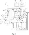
- Fig. 1 shows a schematic view of an extracorporeal blood treatment device (dialysis machine) 2.
- the blood treatment device 2 is basically set up to be used both in continuous and in intermittent blood treatment therapies, in particular renal replacement therapies.
- the blood treatment device 2 is designed in particular as an acute dialysis machine or as an acute dialysis machine and is therefore essentially prepared for use in intensive care units with predominantly unstable patients.
- a large number of different blood treatment therapies e.g.
- SCUF slow continuous ultrafiltration
- CWH continuous venous-venous hemofiltration
- CVVHD continuous venous-venous hemodialysis
- CVVHDF continuous venous-venous hemodiafiltration
- TPE therapeutic plasma exchange
- dilution modes e.g. predilution, postdilution, pre- and postdilution
- types of anticoagulation e.g. none, heparin, citrate, etc.
- the blood treatment device 2 basically has an extracorporeal circuit 4, a dialyzer (hemofilter) 6 and a dialysis fluid circuit 8.
- the extracorporeal circuit 4 and the dialysis fluid circuit 8 are separated from one another by a membrane 10 provided in the dialyzer 6, through which blood can be filtered using a dialysis fluid solution or without using a dialysis fluid solution.
- the extracorporeal circuit 4 comprises an arterial section 12 and a venous section 14. It is basically provided that the arterial section 12, in particular one end thereof, is to be connected to or connected to an artery of a patient, in particular an intensive care patient. It is further provided that the venous section 14, in particular one end thereof, is to be connected to or connected to a vein of a patient, in particular an intensive care patient.
- the arterial section 12 has an arterial pressure sensor 18, an (arterial) blood pump 20 and a dialyzer inlet pressure sensor 22 in a blood flow direction towards the dialyzer 6.
- the venous section 14 has a venous expansion chamber or air trap 26, a safety air detector 28 and a safety valve 30 in a blood flow direction towards a venous end 24.
- a venous pressure can be measured via a venous pressure sensor 32.
- the venous expansion chamber 26 is connected to a substitution solution bag / container 34.
- a substitution solution pump 36 is provided and set up to pump a substitution solution from the substitution solution bag 34 into the extracorporeal blood circuit 4, in particular into the venous section 14 of the same (into the venous expansion chamber 26).
- the dialysis fluid circuit 8 has at least one outlet 38 for ultrafiltrate / used dialysis fluid (dialysate) / another fluid.
- the ultrafiltrate / dialysate / the other liquid can flow via the drain 38 from the dialyzer 6 to a collecting bag / container 40 for ultrafiltrate / dialysate / etc..
- an ultrafiltrate pressure sensor 42, a blood leak detector 44 and an ultrafiltrate pump 46 are arranged or provided in a flow direction towards the collecting bag 40.
- a further bag / container 48 is provided in addition to the substitution solution bag 34 and the collecting bag 40.
- the bag 48 can contain, for example, a substitution solution / fluid or a dialysis fluid, depending on the desired blood treatment therapy to be carried out.
- the extracorporeal blood treatment device 2 i.e. a blood treatment therapy in which dialysis fluid flows through the dialyzer 6 and thus a substance transport from the extracorporeal circuit 4 to the dialysis fluid circuit 8 both via diffusion and via If convection occurs, the bag contains 48 dialysis fluid. If a first valve 50 is now opened and both a second valve 52 and a third valve 54 are closed, the dialysis fluid can be pumped to the dialyzer 6 via a pump 56.
- the Bag 48 contain a substitute solution. If the first valve 50 and the second valve 52 are now closed and the third valve 54 is opened, the substitution solution can be pumped from the bulge 48 into the arterial section 12 of the extracorporeal circuit 4 (predilution).
- the substitution solution can be pumped from the bag 48 into the venous section 14 of the extracorporeal circuit 4 (post-dilution).
- the substitution solution can be pumped from the bag 48 both into the arterial section 12 and into the venous section 14 of the extracorporeal circuit (pre- and post-dilution).
- pre- and post-dilution can also be achieved in that the substitution solution is pumped from the substitution solution bag 34 into the venous section 14 of the extracorporeal circuit 4 by means of the substitution solution pump 36 (post-dilution), and that at the same time the substitution solution is pumped from the bag 48 is pumped by means of the pump (substitution solution pump) 56 into the arterial section 12 of the extracorporeal circuit 4 (predilution).
- a liquid heater 58 and a pressure sensor 60 are provided between the pump 56 and the valve arrangement consisting of the first valve 50, the second valve 52 and the third valve 54.
- Load cells namely a first load cell 62, a second load cell 64 and a third load cell 66 are arranged on each of the three bags, that is to say the substitution solution bag 34, the collecting bag 40 and the bag 48.
- the first load cell 62 is basically set up to measure or monitor the weight of the substitution solution bag 34.
- the second load cell 64 is basically set up to measure or monitor the weight of the collecting bag 40.
- the third load cell 66 is basically set up to measure or monitor the weight of the bag 48.
- the extracorporeal blood treatment device 2 also has a control unit (CPU) 68 which receives information from the sensors provided in the blood treatment device 2 and which controls the actuators provided in the blood treatment device 2. According to the disclosure, software-supported therapy is thus provided in particular.
- the control unit 68 receives information from the arterial pressure sensor 18, the dialyzer inlet pressure sensor 22, the safety air detector 28, the venous pressure sensor 32, the ultrafiltrate pressure sensor 42, the blood leak detector 44, the pressure sensor 60, the first load cell 62, the second load cell 64, the third Load cell 66, etc.
- the control unit 68 controls in particular the blood pump 20, the Safety valve 30, the substitution solution pump 36, the ultrafiltrate pump 46, the first valve 50, the second valve 52, the third valve 54, the pump 56, the liquid heater 58, etc. on. Furthermore, the control unit 68 is in exchange with a user interface 70 designed as a display with a touch screen. For example, the control unit 68 can be set up to display a warning or an alarm on the user interface 70. Furthermore, information entered by a user on the user interface 70 can be passed on to the control unit 68.
- the present disclosure essentially relates to the control of the substitution solution pump 36 and the pump 56 (if the pump 56 operates as a substitution solution pump).
- the present disclosure relates essentially to a control performed by the control unit 68.
- the control unit 68 can in particular calculate a difference or a residue between an ideal / optimal setpoint volume of the supplied substitution solution set by a user and an actually controlled volume of the supplied substitution solution.
- the control unit 68 uses a time profile of the flow rate of the substitution solution pump 36 or the pump 56.
- control unit 68 determines / if the control unit 68 becomes aware (through a corresponding calculation) that there is a difference or a lag between an ideal / optimal setpoint volume set by a user and an actually / really controlled volume of the supplied substitution solution, increases the control unit 68 temporarily adjusts a controlled flow rate of the substitution solution pump 36 or the pump 56 by a predetermined fixed percentage. That is, the flow rate of the substitution solution pump 36 or the pump 56 is set greater than a normally required flow rate by a predetermined fixed percentage.
- a normally required flow rate is to be understood as a flow rate by means of which the ideal / optimal target volume set by a user could be achieved if there were no residue / no difference between the set target volume and the actually controlled volume of the supplied substitution solution.
- the predetermined fixed percentage can in principle be set to a value between 1% and 5%. It can also be provided that the predetermined, fixed percentage is set higher when the deviation between the actual volume and the target volume is large than when the deviation between the actual volume and the target volume is small. For example, the predetermined fixed percentage can be set to 1% when the deviation is small, and the predetermined fixed percentage can be set to 5% when the deviation is large. In any case, however, the percentage which is set by the control unit (depending on the difference / the backlog) is already preset and predetermined.
- the flow rate / the volume flow of the substitution solution pump 36 or the pump 56 is increased by the predetermined fixed percentage until the difference or the residue between the actually controlled volume and the ideal target volume is no longer present, i.e. the actually controlled volume (again ) corresponds to the ideal target volume.
- Fig. 2 shows the sequence according to the disclosure of an automatic volume compensation of a substitution solution.
- the control unit 68 first calculates an actually controlled volume of the substitution solution, which is fed to an extracorporeal circuit 4.
- the control unit 68 compares the volume actually controlled and supplied to the extracorporeal circuit 4 with a (predetermined) ideal target volume. If the volume actually supplied or actual volume is less than the ideal target volume, the control unit increases the flow rate of a substitution solution pump by a predetermined, fixed percentage, which is a maximum of 5%.
- the control unit 68 then continues to compare the setpoint volume with the actual volume. Only when the setpoint volume is equal to the actual volume does the control unit 68 reset the flow rate of the substitution solution pump to the initial value / actually required value. The routine shown does not end until the end of therapy.
- FIG. 8 shows a diagram in which a time profile of a substitution solution flow rate Q controlled by the control unit 68 is controlled by the substitution solution pump 36 or the pump 56 is shown.
- Fig. 3 shows Fig. 3 that when the substitution solution pump 36 or the pump 56 is started or restarted, the substitution solution flow rate Q increases slowly / continuously / linearly (from zero) in a controlled manner, so that a desired ideal flow rate Q set by a user would ideally result that the ideal / optimal set volume would be supplied to the extracorporeal circuit 4 (if it were / would have been set from the beginning), is only reached at a point in time t1.
- the controlled substitution fluid flow rate Q is controlled not set at time t1 (yet) on the by the user ideal flow rate Q ideal set, but initially increases further linearly, is and reaches Although controlled to a controlled flow rate Q which is opposite to the ideal flow rate Q ideal is increased by a predetermined, fixed percentage.
- a controlled flow rate Q which is opposite to the ideal flow rate Q ideal is increased by a predetermined, fixed percentage.
- the controlled flow rate is temporarily held at a constant value until the volume that has not yet been supplied when starting (see "-V" in Fig. 3 ), i.e. the backlog or the difference, has been fully compensated (see "+ V in Fig. 3 ).
- the controlled flow rate Q is finally adjusted to the ideal flow rate Q ideal controlled.
Landscapes
- Health & Medical Sciences (AREA)
- Heart & Thoracic Surgery (AREA)
- Vascular Medicine (AREA)
- Engineering & Computer Science (AREA)
- Anesthesiology (AREA)
- Biomedical Technology (AREA)
- Hematology (AREA)
- Life Sciences & Earth Sciences (AREA)
- Animal Behavior & Ethology (AREA)
- General Health & Medical Sciences (AREA)
- Public Health (AREA)
- Veterinary Medicine (AREA)
- Cardiology (AREA)
- Urology & Nephrology (AREA)
- Emergency Medicine (AREA)
- Physics & Mathematics (AREA)
- Fluid Mechanics (AREA)
- External Artificial Organs (AREA)
Applications Claiming Priority (1)
| Application Number | Priority Date | Filing Date | Title |
|---|---|---|---|
| DE102019126048.5A DE102019126048A1 (de) | 2019-09-26 | 2019-09-26 | Blutbehandlungsvorrichtung mit automatischer Substitutionsvolumenkompensation |
Publications (1)
| Publication Number | Publication Date |
|---|---|
| EP3797804A1 true EP3797804A1 (fr) | 2021-03-31 |
Family
ID=72615683
Family Applications (1)
| Application Number | Title | Priority Date | Filing Date |
|---|---|---|---|
| EP20197629.7A Pending EP3797804A1 (fr) | 2019-09-26 | 2020-09-23 | Dispositif de traitement du sang à compensation automatique du volume de substitution |
Country Status (3)
| Country | Link |
|---|---|
| US (1) | US20210093772A1 (fr) |
| EP (1) | EP3797804A1 (fr) |
| DE (1) | DE102019126048A1 (fr) |
Citations (10)
| Publication number | Priority date | Publication date | Assignee | Title |
|---|---|---|---|---|
| DE3313421A1 (de) | 1983-04-13 | 1984-10-25 | Fresenius AG, 6380 Bad Homburg | Vorrichtung zur extrakorporalen reinigung von blut |
| EP0321754A1 (fr) | 1987-12-19 | 1989-06-28 | Fresenius AG | Dispositif pour le traitement sanguin |
| EP0373455A1 (fr) | 1988-12-13 | 1990-06-20 | B. Braun Melsungen AG | Dispositif pour hémofiltration et hémodiafiltration en continue |
| WO1992000768A1 (fr) | 1990-07-06 | 1992-01-23 | Renalaid Limited | Appareil et procedes de regulation de fluide |
| WO1994011093A1 (fr) | 1992-11-12 | 1994-05-26 | Althin Medical, Inc. | Procede et appareil de dialyse renale |
| CA2580848A1 (fr) | 1993-02-12 | 1994-08-13 | Gambro Industries Sas | Technique pour le traitement extracorporel du sang |
| US5470483A (en) | 1993-03-22 | 1995-11-28 | Hospal Industrie | Device and method for controlling the balance of fluids in an extracorporeal blood circuit |
| US9089639B2 (en) | 2011-02-01 | 2015-07-28 | Fresenius Medical Care Deutschland Gmbh | Method and device for controlling an extracorporeal blood treatment apparatus |
| EP3015123A1 (fr) * | 2014-10-29 | 2016-05-04 | B. Braun Avitum AG | Appareil de thérapie de substitution rénale aiguë |
| WO2018017623A1 (fr) | 2016-07-18 | 2018-01-25 | Nxstage Medical, Inc. | Dispositifs, procédés, et systèmes d'équilibrage de débits |
Family Cites Families (4)
| Publication number | Priority date | Publication date | Assignee | Title |
|---|---|---|---|---|
| US5486286A (en) * | 1991-04-19 | 1996-01-23 | Althin Medical, Inc. | Apparatus for performing a self-test of kidney dialysis membrane |
| US8246566B2 (en) * | 2006-12-22 | 2012-08-21 | Baxter International Inc. | Total fluid loss control system |
| ITMI20110442A1 (it) * | 2011-03-21 | 2012-09-22 | Gambro Lundia Ab | Apparecchiatura per il trattamento extracorporeo di sangue. |
| WO2018099785A1 (fr) * | 2016-11-29 | 2018-06-07 | Gambro Lundia Ab | Dossiers de patient et de traitement |
-
2019
- 2019-09-26 DE DE102019126048.5A patent/DE102019126048A1/de active Pending
-
2020
- 2020-09-23 EP EP20197629.7A patent/EP3797804A1/fr active Pending
- 2020-09-25 US US17/032,111 patent/US20210093772A1/en active Pending
Patent Citations (11)
| Publication number | Priority date | Publication date | Assignee | Title |
|---|---|---|---|---|
| DE3313421A1 (de) | 1983-04-13 | 1984-10-25 | Fresenius AG, 6380 Bad Homburg | Vorrichtung zur extrakorporalen reinigung von blut |
| EP0321754A1 (fr) | 1987-12-19 | 1989-06-28 | Fresenius AG | Dispositif pour le traitement sanguin |
| EP0373455A1 (fr) | 1988-12-13 | 1990-06-20 | B. Braun Melsungen AG | Dispositif pour hémofiltration et hémodiafiltration en continue |
| WO1992000768A1 (fr) | 1990-07-06 | 1992-01-23 | Renalaid Limited | Appareil et procedes de regulation de fluide |
| WO1994011093A1 (fr) | 1992-11-12 | 1994-05-26 | Althin Medical, Inc. | Procede et appareil de dialyse renale |
| CA2580848A1 (fr) | 1993-02-12 | 1994-08-13 | Gambro Industries Sas | Technique pour le traitement extracorporel du sang |
| EP0829265B1 (fr) | 1993-02-12 | 2001-09-05 | Hospal Industrie | Méthode pour amorcer un circuit à usages multiples pour le traitement extracorporel du sang |
| US5470483A (en) | 1993-03-22 | 1995-11-28 | Hospal Industrie | Device and method for controlling the balance of fluids in an extracorporeal blood circuit |
| US9089639B2 (en) | 2011-02-01 | 2015-07-28 | Fresenius Medical Care Deutschland Gmbh | Method and device for controlling an extracorporeal blood treatment apparatus |
| EP3015123A1 (fr) * | 2014-10-29 | 2016-05-04 | B. Braun Avitum AG | Appareil de thérapie de substitution rénale aiguë |
| WO2018017623A1 (fr) | 2016-07-18 | 2018-01-25 | Nxstage Medical, Inc. | Dispositifs, procédés, et systèmes d'équilibrage de débits |
Also Published As
| Publication number | Publication date |
|---|---|
| DE102019126048A1 (de) | 2021-04-01 |
| US20210093772A1 (en) | 2021-04-01 |
Similar Documents
| Publication | Publication Date | Title |
|---|---|---|
| EP0960625B1 (fr) | Dispositif de sécurité pour un appareil de traitement du sang | |
| EP0373455B1 (fr) | Dispositif pour hémofiltration et hémodiafiltration en continue | |
| DE102007026010B4 (de) | Vorrichtung zur Steuerung einer Einrichtung zum Fördern von Blut und Verfahren zum Fördern von Blut in einer Blutleitung eines extrakorporalen Blutkreislaufs einer extrakorporalen Blutbehandlungsvorrichtung | |
| EP2249898B1 (fr) | Procédé de détermination de la fraction de recirculation dans une fistule et/ou de la recirculation cardiopulmonaire, par rapport à la somme de la recirculation dans la fistule et de la recirculation cardiopulmonaire | |
| DE10355042B3 (de) | Verfahren und Vorrichtung zum Erkennen von Störungen des Blutflusses in einem extrakorporalen Blutkreislauf | |
| DE4240681C2 (de) | Vorrichtung zur Hämodialyse ohne Antikoagulation | |
| WO2015110437A1 (fr) | Dispositif et procédé de régulation et de définition du débit de pompes d'assistance circulatoire | |
| EP2897669A1 (fr) | Dispositif et procédé permettant d'identifier une recirculation pendant un traitement sanguin extracorporel | |
| EP2231226A1 (fr) | Procédé et dispositif pour déterminer la pression transmembranaire lors d'un traitement extracorporel du sang | |
| DE102008045422A1 (de) | Vorrichtung zum Befüllen eines Filters und Verfahren hierzu | |
| EP2985045A1 (fr) | Procede de reglage d'un flux sanguin dans un dispositif de dialyse et dispositif de dialyse | |
| EP3231464A1 (fr) | Procédé et dispositif destinés au traitement du sang extracorporel | |
| EP2783714B1 (fr) | Procédé et dispositif de détermination d'un état de recirculation | |
| EP3820542B1 (fr) | Dispositif de commande et/ou de régulation permettant d'éliminer un fluide contenu dans un filtre sanguin | |
| EP3797803B1 (fr) | Dispositif de traitement du sang avec surveillance améliorée du poids des sacs | |
| EP3797804A1 (fr) | Dispositif de traitement du sang à compensation automatique du volume de substitution | |
| EP4326361A1 (fr) | Procédé de commande d'un dispositif de traitement du sang et dispositifs associés | |
| EP4297817A1 (fr) | Procédé d'analyse d'une valeur de pression mesurée, et dispositifs | |
| DE102018108492A1 (de) | Blutschlauchsatz, Steuer- oder Regelvorrichtung, Blutbehandlungsvorrichtung und Verfahren für die Single Needle-Behandlung | |
| EP3795191B1 (fr) | Dispositif de traitement du sang à réduction automatique d'un débit de solution de substitution | |
| EP2988661B1 (fr) | Unité de commande et procédé de détermination d'une pression dans un vaisseau sanguin, en particulier dans une fistule artério-veineuse | |
| EP4213908A1 (fr) | Procédé d'identification du type d'un filtre médical et dispositifs | |
| EP3797805B1 (fr) | Dispositif de traitement du sang à élimination automatique de l'air | |
| WO2023104884A1 (fr) | Dispositif de traitement du sang ayant une pompe à sang couplée et dispositif à air comprimé | |
| WO2024175661A1 (fr) | Dispositif de traitement du sang avec compensation des changements de température ambiante |
Legal Events
| Date | Code | Title | Description |
|---|---|---|---|
| PUAI | Public reference made under article 153(3) epc to a published international application that has entered the european phase |
Free format text: ORIGINAL CODE: 0009012 |
|
| STAA | Information on the status of an ep patent application or granted ep patent |
Free format text: STATUS: THE APPLICATION HAS BEEN PUBLISHED |
|
| AK | Designated contracting states |
Kind code of ref document: A1 Designated state(s): AL AT BE BG CH CY CZ DE DK EE ES FI FR GB GR HR HU IE IS IT LI LT LU LV MC MK MT NL NO PL PT RO RS SE SI SK SM TR |
|
| AX | Request for extension of the european patent |
Extension state: BA ME |
|
| STAA | Information on the status of an ep patent application or granted ep patent |
Free format text: STATUS: REQUEST FOR EXAMINATION WAS MADE |
|
| 17P | Request for examination filed |
Effective date: 20210518 |
|
| STAA | Information on the status of an ep patent application or granted ep patent |
Free format text: STATUS: EXAMINATION IS IN PROGRESS |
|
| 17Q | First examination report despatched |
Effective date: 20230704 |