EP3797701A1 - Radiography apparatus - Google Patents
Radiography apparatus Download PDFInfo
- Publication number
- EP3797701A1 EP3797701A1 EP20198792.2A EP20198792A EP3797701A1 EP 3797701 A1 EP3797701 A1 EP 3797701A1 EP 20198792 A EP20198792 A EP 20198792A EP 3797701 A1 EP3797701 A1 EP 3797701A1
- Authority
- EP
- European Patent Office
- Prior art keywords
- arm
- rotation
- image receiving
- receiving unit
- friction
- Prior art date
- Legal status (The legal status is an assumption and is not a legal conclusion. Google has not performed a legal analysis and makes no representation as to the accuracy of the status listed.)
- Granted
Links
Images











Classifications
-
- A—HUMAN NECESSITIES
- A61—MEDICAL OR VETERINARY SCIENCE; HYGIENE
- A61B—DIAGNOSIS; SURGERY; IDENTIFICATION
- A61B6/00—Apparatus or devices for radiation diagnosis; Apparatus or devices for radiation diagnosis combined with radiation therapy equipment
- A61B6/44—Constructional features of apparatus for radiation diagnosis
- A61B6/4429—Constructional features of apparatus for radiation diagnosis related to the mounting of source units and detector units
- A61B6/4435—Constructional features of apparatus for radiation diagnosis related to the mounting of source units and detector units the source unit and the detector unit being coupled by a rigid structure
- A61B6/4441—Constructional features of apparatus for radiation diagnosis related to the mounting of source units and detector units the source unit and the detector unit being coupled by a rigid structure the rigid structure being a C-arm or U-arm
-
- A—HUMAN NECESSITIES
- A61—MEDICAL OR VETERINARY SCIENCE; HYGIENE
- A61B—DIAGNOSIS; SURGERY; IDENTIFICATION
- A61B6/00—Apparatus or devices for radiation diagnosis; Apparatus or devices for radiation diagnosis combined with radiation therapy equipment
- A61B6/44—Constructional features of apparatus for radiation diagnosis
-
- A—HUMAN NECESSITIES
- A61—MEDICAL OR VETERINARY SCIENCE; HYGIENE
- A61B—DIAGNOSIS; SURGERY; IDENTIFICATION
- A61B6/00—Apparatus or devices for radiation diagnosis; Apparatus or devices for radiation diagnosis combined with radiation therapy equipment
- A61B6/10—Safety means specially adapted therefor
- A61B6/102—Protection against mechanical damage, e.g. anti-collision devices
- A61B6/105—Braking or locking devices
-
- A—HUMAN NECESSITIES
- A61—MEDICAL OR VETERINARY SCIENCE; HYGIENE
- A61B—DIAGNOSIS; SURGERY; IDENTIFICATION
- A61B6/00—Apparatus or devices for radiation diagnosis; Apparatus or devices for radiation diagnosis combined with radiation therapy equipment
- A61B6/40—Arrangements for generating radiation specially adapted for radiation diagnosis
-
- A—HUMAN NECESSITIES
- A61—MEDICAL OR VETERINARY SCIENCE; HYGIENE
- A61B—DIAGNOSIS; SURGERY; IDENTIFICATION
- A61B6/00—Apparatus or devices for radiation diagnosis; Apparatus or devices for radiation diagnosis combined with radiation therapy equipment
- A61B6/44—Constructional features of apparatus for radiation diagnosis
- A61B6/4405—Constructional features of apparatus for radiation diagnosis the apparatus being movable or portable, e.g. handheld or mounted on a trolley
-
- A—HUMAN NECESSITIES
- A61—MEDICAL OR VETERINARY SCIENCE; HYGIENE
- A61B—DIAGNOSIS; SURGERY; IDENTIFICATION
- A61B6/00—Apparatus or devices for radiation diagnosis; Apparatus or devices for radiation diagnosis combined with radiation therapy equipment
- A61B6/44—Constructional features of apparatus for radiation diagnosis
- A61B6/4411—Constructional features of apparatus for radiation diagnosis the apparatus being modular
-
- A—HUMAN NECESSITIES
- A61—MEDICAL OR VETERINARY SCIENCE; HYGIENE
- A61B—DIAGNOSIS; SURGERY; IDENTIFICATION
- A61B6/00—Apparatus or devices for radiation diagnosis; Apparatus or devices for radiation diagnosis combined with radiation therapy equipment
- A61B6/44—Constructional features of apparatus for radiation diagnosis
- A61B6/4476—Constructional features of apparatus for radiation diagnosis related to motor-assisted motion of the source unit
-
- A—HUMAN NECESSITIES
- A61—MEDICAL OR VETERINARY SCIENCE; HYGIENE
- A61B—DIAGNOSIS; SURGERY; IDENTIFICATION
- A61B6/00—Apparatus or devices for radiation diagnosis; Apparatus or devices for radiation diagnosis combined with radiation therapy equipment
- A61B6/54—Control of apparatus or devices for radiation diagnosis
-
- A—HUMAN NECESSITIES
- A61—MEDICAL OR VETERINARY SCIENCE; HYGIENE
- A61B—DIAGNOSIS; SURGERY; IDENTIFICATION
- A61B6/00—Apparatus or devices for radiation diagnosis; Apparatus or devices for radiation diagnosis combined with radiation therapy equipment
- A61B6/58—Testing, adjusting or calibrating thereof
- A61B6/586—Detection of faults or malfunction of the device
Definitions
- the present disclosure relates to a radiography apparatus.
- a radiography apparatus which includes an arm having two ends.
- An irradiation unit (X-ray tube) that emits radiation is provided at one end of the arm.
- An image receiving unit (image receiving device) that receives the radiation emitted from the irradiation unit is provided at the other end of the arm.
- This arm is supported so as to be rotatable with respect to a main body of the radiography apparatus. The arm is rotated such that the irradiation unit and the image receiving unit can be positioned in any posture around a subject while maintaining a relative position.
- JP1994-070918A JP-H06-070918A
- an arm can be manually rotated.
- the load of an operation force may be small or large according to circumstances.
- the load of the operation force of the arm is small in a positioning stage before surgery. After the surgery is started, it is preferable that the arm is not inadvertently rotated due to contact with a person.
- An object of the technology according to the present disclosure is to provide a radiography apparatus that can change a load due to a manual operation force of an arm.
- a radiography apparatus comprising: an irradiation unit that emits radiation; an arm that is capable of holding the irradiation unit and an image receiving unit that receives the radiation, which has been emitted from the irradiation unit and transmitted through a subject, in a facing posture; a support portion that supports the arm; a displacement mechanism that displaces the arm with respect to the support portion; and a friction mechanism that is switchable between a first state in which a frictional force is applied to the arm in a direction opposite to a direction in which the arm is displaced and a second state in which the frictional force applied to the arm is less than the frictional force in the first state.
- the radiography apparatus comprises the displacement mechanism that displaces the arm and the friction mechanism that is switchable between the first state in which the frictional force is applied to the arm in the direction opposite to the direction in which the arm is displaced and the second state in which the frictional force applied to the arm is less than that in the first state. Therefore, the friction mechanism is switched between the first state and the second state to change a load due to the manual operation force of the arm.
- the radiography apparatus may further comprise an operation portion that switches the friction mechanism between the first state and the second state.
- the operator can optionally switch the frictional force. For example, before surgery, it is possible to reduce the frictional force such that positioning is performed with a small force. During surgery, it is possible to increase the frictional force in order to prevent the arm from being inadvertently rotated due to the application of an unintended external force to the arm such as the collision of the operator with the arm.
- the arm in the radiography apparatus according to the first aspect or the second aspect, the arm may be displaced by only a manual operation.
- the arm is not displaced by an electromotive force, but can be displaced by only a manual operation. Therefore, it is possible to reduce the size and weight of the entire radiography apparatus.
- a large-sized radiography apparatus includes a mechanism that electrically displaces the arm.
- the operation force of the arm is controlled through a complicated mechanism such as an electric mechanism.
- the friction mechanism according to the technology of the present disclosure can switch the operation force of the arm with a relatively simple structure even in a case in which the arm is displaced by only a manual operation to reduce the size and weight of the apparatus. Therefore, the technology of the present disclosure is particularly effective for an apparatus with a small size and weight in which the arm is displaced by only a manual operation.
- the displacement mechanism may be a rotation mechanism that rotates the arm.
- this configuration is particularly effective in a case in which the friction mechanism capable of switching the frictional force is combined with the rotation mechanism.
- the image receiving unit may be attachable to and detachable from the arm.
- the radiography apparatus may further comprise: an attachment and detachment detection unit that detects whether or not the image receiving unit is detached from the arm; and a control unit that performs control to switch the friction mechanism to the first state in a case in which the attachment and detachment detection unit detects that the image receiving unit is detached from the arm and to switch the friction mechanism to the second state in a case in which the attachment and detachment detection unit detects that the image receiving unit is attached to the arm.
- the weight balance of the arm may change and the arm may be inadvertently rotated.
- the frictional force is increased in operative association with the detachment of the image receiving unit. Therefore, it is possible to suppress the inadvertent rotation of the arm even in a case in which the image receiving unit is detached.
- the frictional force in the first state may be greater than a maximum weight of the image receiving unit that is capable of being attached to the arm.
- the radiography apparatus may further comprise an electromagnetic brake that locks the rotation of the arm by the rotation mechanism.
- the radiography apparatus includes the electromagnetic brake that locks the rotation of the arm in addition to the friction mechanism. Therefore, the electromagnetic brake locks the rotation of the arm to prohibit the rotation of the arm as necessary.
- the rotation mechanism may have a rotation shaft that is rotated with the rotation of the arm and the friction mechanism may comprise a friction shaft, a frictional force generation unit that is attached to the friction shaft and generates a frictional force, and a clutch that switches connection and disconnection between the rotation shaft and the friction shaft to switch between the first state and the second state.
- the components of the rotation mechanism and the components of the friction mechanism are operatively associated with each other to reduce the size of each mechanism, as compared to a case in which the rotation mechanism and the friction mechanism are independently configured.
- the rotation mechanism may have a rotation shaft that is rotated with the rotation of the arm and the electromagnetic brake may be connected to the rotation shaft.
- the components of the rotation mechanism and the electromagnetic brake are connected to each other to reduce the size of each mechanism, as compared to a case in which the rotation mechanism and the electromagnetic brake are independently configured.
- the arm may have an arc shape in a side view.
- the rotation mechanism may include a first rotation mechanism comprising a track portion that is provided in the support portion and supports the arm so as to be movable along the arc shape, a fitting portion that is formed in an outer peripheral portion of the arm and is fitted to the track portion, and a first rotation shaft as the rotation shaft.
- the arm may be moved with respect to the track portion to be orbitally rotated about a center of the arc shape as a rotation center.
- the arm since the arm can be orbitally rotated along the arc shape, the irradiation unit and the image receiving unit can be rotated about the body axis of the subject.
- the rotation mechanism may further include a belt that has one end fixed to an end of the arm at which the irradiation unit is provided and the other end fixed to an end f the arm at which the image receiving unit is provided.
- the belt may be wound around the first rotation shaft.
- a rack and pinion system or a system in which a chain and a sprocket are combined are considered instead of the belt.
- the weight of the apparatus can be less than that in these systems.
- the rotation mechanism may include a second rotation mechanism comprising a second rotation shaft as the rotation shaft that has one end fixed to the arm and a bearing that is provided in the support portion.
- the arm may be rotated about the second rotation shaft with respect to the bearing to reverse positions of the irradiation unit and the image receiving unit with respect to the subject.
- the arm since the arm is rotatable about the rotation shaft, it is possible to switch between an overtube posture in which the irradiation unit is disposed above the image receiving unit and an undertube posture in which the irradiation unit is disposed below the image receiving unit.
- the radiography apparatus may further comprise an operation handle that is provided independently of the arm and is manually operated to input an operation force for displacing the arm to the displacement mechanism.
- the operation handle makes it possible to operate the arm, without directly operating the arm. Further, since the arm is displaced through the displacement mechanism, the amount of displacement of the arm can be adjusted more easily than that in a case in which the arm is directly operated.
- the gear ratio of the displacement mechanism can be set to adjust the relationship between the amount of operation of the operation handle and the amount of displacement of the arm. Therefore, the setting of reducing the amount of displacement of the arm with respect to the amount of displacement of the operation handle is relatively simple.
- the operation handle makes it easy to finely adjust the amount of displacement of the arm.
- the arm that holds the irradiation unit and the image receiving unit is used during surgery. Since the operation handle is provided independently of the arm, it is possible to separate an operation part operated by the operator from an operation part operated by the assistant. Therefore, the following method can also be used: the assistant rotates the arm while avoiding the operation part contaminated by contact with the operator.
- an arrow X indicates the front-rear direction of the radiography apparatus
- an arrow Y indicates the width direction of the radiography apparatus
- an arrow Z indicates the vertical direction.
- a radiography apparatus 10 is an apparatus that captures a radiographic image of a subject H.
- the radiography apparatus 10 can capture, for example, moving images and still images of the subject H.
- the capture of the moving image is performed, for example, in a case in which a treatment target part of the subject H is displayed as a moving image during surgery (also referred to as fluoroscopy).
- the moving image of the subject H is displayed on a monitor (not illustrated) that is provided separately from the radiography apparatus 10.
- data of the captured moving image may be stored in a memory of the radiography apparatus 10.
- the captured still image may be displayed on the monitor or may be stored in the memory of the radiography apparatus 10.
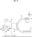
- the radiography apparatus 10 includes an arm 12 (referred to as a C-arm or the like) having a C-shape (an arc shape) in a side view and a main body 16 to which a connection portion 14 is attached.
- an arm 12 referred to as a C-arm or the like
- a C-shape an arc shape
- main body 16 to which a connection portion 14 is attached.
- the side of the radiography apparatus 10 on which the arm 12 is provided is the front side of the radiography apparatus 10 and the side on which the main body 16 is provided is the rear side of the radiography apparatus 10.
- the arm 12 has two ends. An irradiation unit 18 is provided at one end of the arm 12 and an image receiving unit 20 is provided at the other end.
- the arm 12 can hold the irradiation unit 18 and the image receiving unit 20 in a posture in which they face each other. A space, into which the subject H and a bed S on which the subject H lies supine can be inserted, is ensured between the irradiation unit 18 and the image receiving unit 20.
- a direction in which the irradiation unit 18 and the image receiving unit 20 are provided on the basis of the arm 12 is referred to as the front side of the arm 12 and the side of the arm 12 is referred to as the rear side of the arm 12.
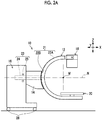
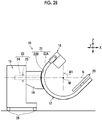
- the arm 12 can be rotated by a manual operation. Specifically, as illustrated in Fig. 2A , the arm 12 can be orbitally rotated about an axis line M (an axis line parallel to the Y axis) with respect to the connection portion 14 by a first rotation mechanism 21 which is an example of a displacement mechanism. Further, the arm 12 can be rotated about an axis line N (an axis line parallel to the X-axis) with respect to the main body 16 by a second rotation mechanism 23 which is an example of the displacement mechanism.
- the connection portion 14 or the main body 16 corresponds to a "support portion" that supports the arm 12.
- the first rotation mechanism 21 comprises a track portion 22B that is provided in the connection portion 14 and a fitting portion 22A that is formed on an outer peripheral surface of the arm 12 and is fitted to the track portion 22B.
- the first rotation mechanism 21 further comprises a pulley shaft 48 as a first rotation shaft, which will be described below, and a belt 46.
- the fitting portion 22A has an arc shape following the shape of the arm 12.
- the track portion 22B has an arc shape that has the same radius as the arc of the arm 12 and supports the arm 12 so as to be movable along the arc shape.
- the track portion 22B has, for example, a groove shape and the fitting portion 22A having a convex shape is fitted to the track portion 22B.
- a roller (not illustrated) that assists the sliding of the fitting portion 22A with respect to the track portion 22B is interposed between the track portion 22B and the fitting portion 22A.
- the fitting portion 22A formed in the arm 12 slides along the track portion 22B formed in the connection portion 14 such that the arm 12 can be orbitally rotated about the axis line M at the center of the arc of the arm 12 as a rotation center with respect to the connection portion 14 and the main body 16.
- the second rotation mechanism 23 comprises a support shaft 24 as a second rotation shaft, one end of which is fixed to the arm 12, and a bearing 25 which is provided in the main body 16.
- the support shaft 24 extends in the front-rear direction (X direction) of the radiography apparatus 10 and has the other end that is supported by the main body 16 through the bearing 25.
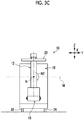
- the support shaft 24 is rotated about the axis line N with respect to the bearing 25 such that the arm 12 and the connection portion 14 are rotatable about the axis line N of the support shaft 24 with respect to the main body 16 as illustrated in Figs. 3A to 3C .
- the posture of the arm 12 in which the irradiation unit 18 is disposed above the image receiving unit 20 as illustrated in Fig. 3A is also referred to as an overtube posture since a radiation tube 32 (see Fig. 1 ) included in the irradiation unit 18 is located above the subject H.
- the posture of the arm 12 in which the irradiation unit 18 is disposed below the image receiving unit 20 illustrated in Fig. 3C is referred to as an undertube posture since the radiation tube 32 is located below the subject H.
- the overtube posture it is possible to increase a distance between the irradiation unit 18 and the subject H (see Fig. 1 ) and thus to capture an image of a relatively wide region, as compared to the undertube posture. Therefore, the overtube posture is mainly used to capture the still image of the subject H.
- the undertube posture since the radiation emitted from the irradiation unit 18 is partially shielded by, for example, the bed S, it is possible to reduce the amount of radiation exposure of a surgeon or an operator (not illustrated) around the subject H (see Fig. 1 ). Therefore, the undertube posture is used for the capture of the moving image of the subject H in which radiation is continuously emitted.
- a plurality of casters 26 are attached to a lower portion of the main body 16 of the radiography apparatus 10 and the operator can push the radiography apparatus 10 with hands to move the radiography apparatus 10 into, for example, an operating room or a hospital ward. That is, the radiography apparatus 10 according to this embodiment is a mobile type.
- the main body 16 includes a control unit 28 that controls each unit of the radiography apparatus 10, such as the irradiation unit 18, and an operation panel 30 that is, for example, a touch panel type.
- the main body 16 comprises various switches (not illustrated) including, for example, a power switch of the radiography apparatus 10, a power supply circuit that supplies power to each unit of the radiography apparatus 10, and a battery.
- the operation panel 30 functions as an operation unit that inputs an operation command to each unit of the radiography apparatus 10 to operate each unit and a display unit that displays various kinds of information, such as a warning message and a radiographic image output from the image receiving unit 20.
- the control unit 28 transmits a control signal to the radiation tube 32 of the irradiation unit 18, which will be described below, to control, for example, the tube voltage, tube current, and irradiation time of radiation of the radiation tube 32.
- the tube voltage is controlled to control the energy of radiation and the tube current and the irradiation time are controlled to control the dose of radiation.
- the control unit 28 controls the radiation tube 32 through a high-voltage generation device (not illustrated).
- imaging imaging conditions including, for example, the tube voltage, the tube current, and the irradiation time are set through the operation panel 30.
- the control unit 28 operates the irradiation unit 18 on the basis of the set imaging conditions.
- the control unit 28 directs the irradiation unit 18 to perform moving image capture irradiation in which the irradiation unit 18 continuously emits radiation such that a moving image of the subject H can be captured.
- the control unit 28 operates a detector of the image receiving unit 20 which will be described below in synchronization with the moving image capture irradiation by the irradiation unit 18.
- the irradiation time is not set as the imaging condition and commands to start and end the capture of a moving image are input through the operation panel 30.
- the control unit 28 directs the irradiation unit 18 to start the emission of radiation under preset imaging conditions.
- the detector repeats an image detection operation at a preset frame rate while the moving image capture irradiation is performed.
- the image output by the detector is transmitted to the control unit 28.
- the control unit 28 sequentially outputs the received images to a monitor (not illustrated). Therefore, the moving image of the subject H is displayed on the monitor.
- control unit 28 directs the irradiation unit 18 to perform still image capture irradiation in which the irradiation unit 18 emits radiation for a shorter time than in the moving image capture irradiation such that a still image of the subject H can be captured.
- the control unit 28 operates the detector of the image receiving unit 20 in synchronization with the irradiation timing in the still image capture irradiation by the irradiation unit 18.
- a command to capture a still image is input through an irradiation switch (not illustrated) that is connected to the control unit 28.
- the irradiation time is, for example, in the order of several tens of milliseconds to several hundreds of milliseconds.
- the control unit 28 operates the irradiation unit 18 on the basis of preset imaging conditions. In the capture of a still image, since the irradiation time is set in the imaging conditions, the irradiation by the irradiation unit 18 ends in a case in which the set irradiation time elapses.
- the detector starts to output the detected image.
- the image output by the detector is transmitted to the control unit 28.
- the control unit 28 stores data of the still image in a memory (not illustrated). Then, the stored still image is displayed on the monitor (not illustrated). Therefore, the still image of the subject H is displayed on the monitor. Further, the still image may be displayed on the operation panel 30 in order to check the captured still image immediately after imaging.
- the irradiation unit 18 comprises a radiation source 31 and an irradiation field limiter 34.
- the radiation source 31 comprises the radiation tube 32 that generates radiation.
- the radiation is, for example, X-rays.
- the radiation tube 32 generates radiation by colliding electrons generated from a cathode with a target (anode). The position where the electrons collide with the target is a focus where radiation is emitted.
- the irradiation field limiter 34 is provided below the radiation source 31.
- the irradiation field limiter 34 (also referred to as a collimator or the like) has a rectangular irradiation opening 34A.
- the radiation generated by the radiation tube 32 is emitted to the subject H through the irradiation opening 34A.
- the irradiation field limiter 34 can adjust the opening area of the irradiation opening 34A.
- the irradiation field limiter 34 has, for example, four shielding plates (not illustrated) that shield radiation. In each of the four shielding plates, each side corresponds to each side of the irradiation opening 34A and defines the irradiation opening 34A. The position of the shielding plates is changed to adjust the opening area of the irradiation opening 34A and the irradiation field of the radiation emitted from the irradiation unit 18 is changed.
- the irradiation unit 18 can be rotated about an axis line of a rotation shaft 36 that extends in the width direction of the radiography apparatus 10 (the Y direction in Fig. 1 ) as a rotation center with respect to the arm 12.
- a pair of attachment plates 38 are fixed to one end of the arm 12.
- the pair of attachment plates 38 are disposed such that both sides of the irradiation unit 18 in the width direction are interposed therebetween and are connected to both side surfaces of the irradiation unit 18 in the width direction.
- the rotation shafts 36 are provided on each of the side surfaces of the irradiation unit 18 facing the attachment plates 38 so as to protrude.
- the rotation shafts 36 are supported by the pair of attachment plates 38 through bearings (not illustrated). Therefore, the irradiation unit 18 can be rotated about the axis line of the rotation shaft 36 as the rotation center with respect to the attachment plates 38 and the orientation of the irradiation opening 34A of the irradiation unit 18 can be changed in the front-rear direction of the arm 12.
- the orientation of the irradiation opening 34A is changed to change the irradiation direction of radiation.
- the irradiation unit 18 is connected to one end of each of a plurality of cables 40 including a signal line for transmitting a control signal and a power line for supplying power.
- the cables 40 are provided in a hollow portion 42 that is formed in the arm 12 and extend along the arm 12.
- the other end of the cable 40 is connected to, for example, the control unit 28 and a power supply circuit (not illustrated) of the main body 16 illustrated in Fig. 1 .
- the image receiving unit 20 is provided at the other end of the arm 12 which is a position facing the irradiation unit 18.
- the image receiving unit 20 is configured by providing the detector in a housing fixed to the arm 12 so as not to be detachable from the housing.
- the image receiving unit 20 has an image receiving surface 20A that receives the radiation which has been emitted from the irradiation unit 18 and then transmitted through the subject H. The radiation carrying the information of the subject H is incident on the image receiving surface 20A.
- the detector is, for example, a flat panel detector (FPD) of a digital radiography (DR) type.
- the FPD has a detection surface in which a plurality of pixels are two-dimensionally arranged and a thin film transistor (TFT) panel (not illustrated) for driving the pixels.
- Radiation is incident on the detection surface of the detector through the image receiving surface 20A.
- the detector converts the incident radiation into an electric signal and outputs a radiographic image indicating the subject H on the basis of the converted electric signal.
- the detector is an indirect conversion type that converts radiation into visible light using a scintillator and converts the converted visible light into an electric signal.
- the detector may be a direct conversion type that directly converts radiation into an electric signal.
- the image receiving unit 20 may have, for example, a configuration in which an image intensifier (I.I) and a camera are combined other than the configuration using the FPD.
- I.I image intensifier
- the image receiving unit 20 is connected to, for example, the control unit 28 and the power supply circuit (not illustrated) of the main body 16 by a cable (not illustrated) including a signal line for transmitting a control signal and a power line for supplying power.
- connection portion 14 of the radiography apparatus 10 is provided with a friction mechanism 44 that applies a frictional force to the arm 12 in a direction opposite to the direction in which the arm 12 is displaced.
- both ends of the belt 46 forming the first rotation mechanism 21 are fixed to both ends of the arm 12, respectively.
- the arm 12 is a hollow cylindrical body. As illustrated in Fig. 5 , the belt 46 and the cables 40 are provided in the hollow portion 42 of the arm 12. In the hollow portion 42, a groove 42A that extends along the arc of the arm 12 is formed in the front inner surface of the arm 12. The belt 46 extends along the arc of the arm 12 while being accommodated in the groove 42A. Therefore, it is possible to suppress interference between the cables 40 and the belt 46 in the hollow portion 42 of the arm 12.
- connection portion 14 is provided with the pulley shaft 48 forming the first rotation mechanism 21.
- the pulley shaft 48 is supported by a frame 52 of the connection portion 14 through a bearing portion 50 so as to be rotatable.
- a pulley 54 is fixed to the pulley shaft 48 so as to be coaxially rotatable and the belt 46 is wound around the pulley 54.
- the belt 46 is a timing belt having a plurality of teeth 46A formed thereon.
- the pulley 54 is a timing pulley having a plurality of grooves 54A formed in an outer peripheral surface.
- the teeth 46A of the belt 46 are engaged with the grooves 54A of the pulley 54 such that the belt 46 and the pulley 54 are operatively associated with each other.
- idlers 56 are provided above and below the pulley 54 in the vertical direction (Z direction) in the connection portion 14, respectively.
- the belt 46 is guided by a pair of idlers 56 while being kept at a predetermined tension and is wound around the pulley 54.
- the belt 46 follows the movement of the arm 12. For example, in a case in which one end of the arm 12 is moved in a direction in which it becomes further away from the connection portion 14 (track portion 22B), the belt 46 is moved in the direction of an arrow P in Fig. 6 , that is, in a direction in which the one end becomes further away from the connection portion 14. In this case, the pulley 54 engaged with the belt 46 is also rotated in the direction of an arrow Q (clockwise in Fig. 6 ) following the movement of the belt 46.
- a first gear 58 is fixed to the pulley shaft 48 so as to be rotatable coaxially with the pulley 54.
- a second gear 60 is engaged with the first gear 58 and the friction mechanism 44 is connected to the second gear 60.
- the friction mechanism 44 includes a friction shaft 62, a frictional force generation unit 64 that is attached to the friction shaft 62 and generates a frictional force, and a clutch 66 that switches connection and disconnection between the pulley shaft 48 and the friction shaft 62.
- the friction shaft 62 is supported by the frame 52 of the connection portion 14 through a bearing 68 so as to be rotatable.
- the friction shaft 62 is inserted into a shaft hole 70A that is formed in a side plate 70.
- the side plate 70 is fixed to the frame 52 at a distance from the frame 52 in the axial direction of the friction shaft 62 (the Y direction in Fig. 7 ).
- the frictional force generation unit 64 comprises two sets of friction plates 72A and 72B that generate a frictional force using contact between friction surfaces, and a biasing portion 74 that biases the friction plates 72A and 72B in a direction in which the friction surfaces are pressed.
- the two sets of friction plates 72A and 72B are provided on both end surfaces of the side plate 70 in the axial direction of the friction shaft 62, respectively.
- a shaft holes (not illustrated) is formed in each of the friction plates 72A and 72B.
- the friction shaft 62 is inserted into the shaft holes such that the friction plates 72A and 72B are attached so as to be movable in the axial direction of the friction shaft 62.
- the movement of one set of friction plates 72A and 72B, which is disposed between the side plate 70 and the frame 52, in the axial direction of the friction shaft 62 is regulated by a regulation plate 76 that is fixed to the friction shaft 62.
- the friction plate 72A that comes into contact with the end surface of the side plate 70 is fixed by a rotation stopper (not illustrated), and is a fixed friction plate that is not rotated regardless of the rotation of the friction shaft 62.
- the friction plate 72B that is provided outside the friction plate 72A (fixed friction plate) in the axial direction of the friction shaft 62 with respect to the side plate 70 is a rotary friction plate that is rotated as the friction shaft 62 is rotated.
- the biasing portion 74 is provided between the side plate 70 and one end of the friction shaft 62 in the axial direction.
- the biasing portion 74 comprises a disc spring unit 78, a pair of buffer plates 80, and a nut 82 that is provided at one end of the friction shaft 62 in the axial direction.
- the disc spring unit 78 includes a plurality of disc springs 78A.
- the disc spring 78A is a disk-shaped spring that has one convex surface and the other concave surface.
- the plurality of disc springs 78A are arranged along the axial direction of the friction shaft 62 so as to be stacked.
- each of the buffer plates 80 is disposed outside the disc spring units 78 in the axial direction of the friction shaft 62.
- One buffer plate 80 is disposed between the disc spring unit 78 and the friction plate 72B.
- the other buffer plate 80 is disposed between the disc spring unit 78 and the nut 82.
- a shaft hole (not illustrated) is formed in each of the buffer plate 80 and the disc spring 78A. The friction shaft 62 is inserted into the shaft holes such that the buffer plate 80 and the disc spring 78A are attached so as to be movable in the axial direction of the friction shaft 62.
- the disc spring unit 78 In a case in which the nut 82 is tightened with the end surface of the disc spring unit 78 in contact with one buffer plate 80, the disc spring unit 78 is moved in the direction in which the one buffer plate 80 is pressed. In a case in which the disc spring unit 78 is moved, a pressing force is applied to each set of the friction plates 72A and 72B through the buffer plate 80. In a case in which the nut 82 is further tightened and the disc spring unit 78 reaches a movement limit, the disc spring 78A is elastically deformed and the disc spring unit 78 contracts in the axial direction of the friction shaft 62. The disc spring unit 78 biases the friction surfaces of the friction plates 72A and 72B in a direction in which they are pressed against each other on the basis of elasticity.
- the operation of the biasing portion 74 causes the friction surfaces of the friction plates 72A and 72B to come into contact with each other and a normal force is generated on the friction surfaces. Therefore, in a case in which the friction shaft 62 is rotated, a frictional force acts on the friction surfaces of the friction plates 72A and 72B in a direction opposite to a rotation direction of the friction shaft 62.
- the clutch 66 is attached to the other end of the friction shaft 62 in the axial direction.
- the clutch 66 is an electromagnetic clutch and includes a housing 84 having an electromagnet (not illustrated) provided therein and a shaft fixing portion 86 fixed to the friction shaft 62.
- the housing 84 and the shaft fixing portion 86 are separated from each other.
- a biasing member (not illustrated) that biases the housing 84 and the shaft fixing portion 86 in the direction in which they become further away from each other is provided between the housing 84 and the shaft fixing portion 86.
- the housing 84 is fixed to the second gear 60.
- Shaft holes 60A and 84A through which the friction shaft 62 is inserted are formed in the housing 84 and the second gear 60, respectively.
- a gap is formed between the outer peripheral surface of the friction shaft 62 and the inner peripheral surfaces of the shaft holes 60A and 84A. That is, the housing 84 and the second gear 60 are not connected to the friction shaft 62.
- the clutch 66 switches connection and disconnection between the second gear 60 and the friction shaft 62 to switch connection and disconnection between the pulley shaft 48 and the friction shaft 62. Specifically, in a case in which the clutch 66 is energized, a magnetic force is generated in the electromagnet provided in the housing 84 and the shaft fixing portion 86 is attracted to the electromagnet against the biasing force of the biasing member (not illustrated). Therefore, the housing 84 and the shaft fixing portion 86 are closely connected.
- the first gear 58, the second gear 60, and the housing 84 of the clutch 66 are rotated with the rotation of the pulley shaft 48.
- the shaft fixing portion 86 of the clutch 66 connected to the housing 84 and the friction shaft 62 to which the shaft fixing portion 86 is fixed are also rotated with the rotation of the pulley shaft 48.
- the friction shaft 62 is rotated with the rotation of the pulley shaft 48 and the frictional force acts on the pulley shaft 48 in the direction opposite to the rotation direction.
- the pulley 54 is fixed to the pulley shaft 48 and the belt 46 fixed to both ends of the arm 12 illustrated in Fig. 4 is wound around the pulley 54.
- a frictional force acts on the pulley shaft 48 in a direction opposite to the rotation direction.
- a frictional force acts on the arm 12 in a direction opposite to the rotation direction of the arm 12.
- the housing 84 fixed to the second gear 60 and the shaft fixing portion 86 fixed to the friction shaft 62 are biased by a biasing member (not illustrated) and are separated from each other. Therefore, the housing 84 and the shaft fixing portion 86 are disconnected and the second gear 60 and the friction shaft 62 are disconnected.
- the operator operates the operation panel 30 (see Fig. 1 ) as an operation unit to perform the switching between the first state and the second state of the friction mechanism 44.
- the control unit 28 transmits a driving signal to the clutch 66 to energize the clutch 66. Therefore, the housing 84 and the shaft fixing portion 86 of the clutch 66 are connected to each other to switch the friction mechanism 44 to the first state in which the frictional force acts on the arm 12.
- the radiography apparatus 10 comprises the first rotation mechanism 21 (an example of the displacement mechanism) that rotates the arm 12 with respect to the connection portion 14 and the friction mechanism 44 that applies a frictional force to the arm 12 in a direction opposite to the direction in which the arm 12 is rotated by the first rotation mechanism 21.
- first rotation mechanism 21 an example of the displacement mechanism
- friction mechanism 44 that applies a frictional force to the arm 12 in a direction opposite to the direction in which the arm 12 is rotated by the first rotation mechanism 21.
- the friction mechanism 44 can be switched between the first state in which a frictional force is applied to the arm 12 in the direction opposite to the direction in which the arm 12 is displaced and the second state in which the frictional force applied to the arm 12 is less than that in the first state. Therefore, the friction mechanism 44 is switched between the first state and the second state to change a load due to the manual operation force of the arm 12 in a case in which the arm 12 is manually rotated.
- the arm 12 may not be rotated by an electromotive force, but may be rotated by only a manual operation. Therefore, it is possible to reduce the size and weight of the entire radiography apparatus 10.
- a large-sized radiography apparatus includes a mechanism that electrically displaces the arm.
- the operation force of the arm is controlled through a complicated mechanism such as an electric mechanism.
- the friction mechanism 44 can switch the operation force of the arm 12 with a relatively simple structure. Therefore, the technology of this embodiment is particularly effective for the radiography apparatus 10 with a small size and weight in which the arm 12 is rotated by only a manual operation.
- the first rotation mechanism 21 has the pulley shaft 48 that is rotated as the arm 12 is rotated.
- the friction mechanism 44 comprises the friction shaft 62, the frictional force generation unit 64 that is attached to the friction shaft 62 and generates a frictional force, and the clutch 66 that switches connection and disconnection between the pulley shaft 48 and the friction shaft 62.
- the operative association between the components of the first rotation mechanism 21 and the components of the friction mechanism 44 makes it possible to reduce the size of each mechanism, as compared to a case in which the first rotation mechanism 21 and the friction mechanism 44 are independently configured.
- the first rotation mechanism 21 has the pulley shaft 48 to which the pulley 54 is fixed and the belt 46 which has both ends fixed to both ends of the arm 12 and is wound around the pulley 54.
- the belt 46 fixed to both ends of the arm 12 is wound around the pulley 54 fixed to the pulley shaft 48, it is possible to operatively associate the components of the first rotation mechanism 21 with the components of the friction mechanism 44 even in a case in which the arm 12 is orbitally rotated.
- a rack and pinion system or a system in which a chain and a sprocket are combined are considered instead of the belt 46.
- the weight of the apparatus can be less than that in these systems.
- a slide mechanism that slides the arm 12 in the horizontal direction (X direction) with respect to the main body 16 is considered as the displacement mechanism for displacing the arm 12.
- a load is less than that in the operation of sliding the arm 12 in the horizontal direction. Therefore, the friction mechanism 44 according to this embodiment which can switch the frictional force is particularly effective in a case in which the friction mechanism 44 is combined with the first rotation mechanism 21 or the second rotation mechanism 23.
- the operator operates the operation panel 30 as the operation unit to perform the switching between the first state and the second state by the friction mechanism 44. That is, the operator can optionally switch the frictional force.
- the frictional force is reduced such that positioning is performed with a small force in a preparatory stage before surgery.
- the frictional force is increased to prevent the arm 12 from being inadvertently rotated due to the application of an unintended external force to the arm 12 such as the collision of the operator with the arm 12.
- a radiography apparatus according to a second embodiment of the present disclosure will be described with reference to Figs. 8 to 12 .
- the same configurations as those in the first embodiment are denoted by the same reference numerals and the description thereof will not be repeated. The description is focused on the differences between the first and second embodiments.
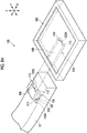
- an image receiving unit 102 is a portable type that is attached to the arm 12 so as to be detachable.
- a detector is provided in a housing so as not to be detachable as in the first embodiment.
- the portable image receiving unit 102 is called, for example, an electronic cassette.
- the image receiving unit 102 is attached to a base 104 that is provided at the other end of the arm 12 so as to be detachable.
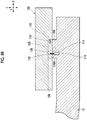
- the base 104 is provided on the upper surface of the other end of the arm 12 and a fitting convex portion 106 is provided uprightly on the base 104.
- Each of the base 104 and the fitting convex portion 106 has a rectangular parallelepiped shape and the width (length in the Y direction) of the fitting convex portion 106 is smaller than the width (length in the Y direction) of the base 104.
- the image receiving unit 102 has a flat rectangular parallelepiped shape.
- a fitting concave portion 108 that is fitted to the fitting convex portion 106 is formed in the lower surface of the image receiving unit 102.
- the fitting concave portion 108 has a rectangular parallelepiped shape and the length (length in the Y direction in Fig. 8A ) of the fitting concave portion 108 in the lateral direction is larger than the width of the fitting convex portion 106 and is smaller than the width of the base 104. Further, the height of the fitting concave portion 108 is substantially equal to the height of the fitting convex portion 106.
- the length (length in the X direction in Fig. 8A ) of the fitting concave portion 108 in the longitudinal direction is larger than the length (length in the X direction) of the base 104 and the fitting convex portion 106.
- One end of the fitting concave portion 108 in the longitudinal direction extends to one side surface of the image receiving unit 102. Since one end of the fitting concave portion 108 is located on one side surface of the image receiving unit 102, a part of one side surface of the image receiving unit 102 is open.
- the image receiving unit 102 is moved in the horizontal direction (X direction) such that the fitting convex portion 106 that is provided uprightly on the base 104 is inserted into the fitting concave portion 108 through the opening formed in one side surface of the image receiving unit 102. Then, the lower surface of the image receiving unit 102 comes into contact with the upper surface of the base 104 in a state in which the fitting convex portion 106 is fitted to the fitting concave portion 108.
- a pair of positioning pins 110 that protrude into the fitting concave portion 108 are provided on the other end surface of the fitting concave portion 108 in the longitudinal direction.
- a pair of pin holes 112 into which the positioning pins 110 are inserted are formed in one side surface of the fitting convex portion 106 which faces the other end surface of the fitting concave portion 108 in the longitudinal direction in a case in which fitting convex portion 106 is fitted to the fitting concave portion 108.
- the pair of positioning pins 110 are inserted into the pair of pin holes 112 such that the image receiving unit 102 is positioned and attached to the base 104, that is, the other end of the arm 12.
- a through hole 114 that extends in the vertical direction (Z direction) is formed in the upper surface of the base 104 and a solenoid 116 is provided below the through hole 114 at the other end of the arm 12.
- An insertion hole 118 having substantially the same diameter as the through hole 114 is formed in the lower surface of the image receiving unit 102.
- the insertion hole 118 of the image receiving unit 102 is formed at a position that communicates with the through hole 114 of the base 104 in a case in which the image receiving unit 102 is positioned and attached to the base 104.
- the solenoid 116 comprises a movable iron core 116A that is inserted into the through hole 114.
- the movable iron core 116A can be expanded and contracted by switching between an energized state and a non-energized state of the solenoid 116.
- the movable iron core 116A is attracted to the main body of the solenoid 116 and a leading end of the movable iron core 116Ais located in the through hole 114 of the base as illustrated in Fig. 8B .
- the image receiving unit 102 is attachable to and detachable from the base 104, that is, the arm 12.
- the movable iron core 116A can be inserted into the insertion hole 118 of the image receiving unit 102 as illustrated in Fig. 8B .
- the solenoid 116 is de-energized in a state in which the image receiving unit 102 is positioned and attached to the other end of the arm 12, the leading end of the movable iron core 116A is inserted into the insertion hole 118 and reaches the image receiving unit 102.
- the movable iron core 116A of the solenoid 116 is also inserted into the insertion hole 118 of the image receiving unit 102, the detachment of the image receiving unit 102 from the base 104, that is, the arm 12 is regulated.
- the solenoid 116 forms an attachment and detachment regulation mechanism that regulates the inadvertent attachment and detachment of the image receiving unit 102 to and from the arm 12 in a state in which the image receiving unit 102 is attached to the arm 12.
- the base 104 is provided with a photo sensor 120 as an attachment and detachment detection unit that detects whether or not the image receiving unit 102 is detached from the arm 12.
- the photo sensor 120 is, for example, a reflective sensor in which a light emitting window through which a light emitting element (not illustrated) emits light and a light receiving window through which a light receiving element (not illustrated) receives light are arranged on the same surface.
- the photo sensor 120 is provided at a position where the light emitting window and the light receiving window are exposed to the outside in a state in which the image receiving unit 102 is not attached to the base 104 and the image receiving unit 102 covers the light emitting window and the light receiving window in a state in which the image receiving unit 102 is attached to the base 104.
- the photo sensor 120 according to this example is disposed on the base 104 in a posture facing the upper surface in Fig. 8A .
- the light emitted from the light emitting window is reflected by the image receiving unit 102 such that the amount of light received through the light receiving window increases.
- the image receiving unit 102 is detached from the base 104 and is retracted from the front surfaces of the light emitting window and the light receiving window, light is not reflected from the image receiving unit 102 and the amount of light received through the light receiving window is reduced.
- the photo sensor 120 detects a change in the light which has been emitted from the light emitting window and then received by the light receiving element to detect whether or not the image receiving unit 102 is detached from the arm 12.
- the photo sensor 120 outputs an on signal as a detection signal to a control unit 126 illustrated in Fig. 11 in a state in which it is detected that the image receiving unit 20 is attached to the arm 12 and outputs an off signal as the detection signal to the control unit 126 illustrated in Fig. 11 in a state in which it is detected that the image receiving unit 20 is detached from the arm 12.
- the portable image receiving unit 102 has, for example, a battery and a wireless communication unit which are not illustrated and can wirelessly communicate with the control unit 126 (see Fig. 11 ) provided in the main body 16.
- the image receiving unit 102 is driven by power from the battery and can be used in a so-called cableless manner. Therefore, the image receiving unit 102 can be used in a state in which it is detached from the arm 12.
- a terminal 122A that is provided in the fitting concave portion 108 of the image receiving unit 102 and a terminal 122B that is provided in the fitting convex portion 106 of the arm 12 illustrated in Fig. 8A come into contact with each other and the image receiving unit 102 and the base 104 are electrically connected.
- the base 104 is connected to, for example, the control unit 126 (see Fig. 11 ) and a power supply circuit (not illustrated) of the main body 16 by a cable (not illustrated) including a signal line for transmitting a control signal and a power line for supplying power. Therefore, in a state in which the image receiving unit 102 is attached to the arm 12, the image receiving unit 102 is connected to, for example, the control unit 126 and the power supply circuit (not illustrated) through a cable (not illustrated).
- a connection portion 14 of the radiography apparatus 100 is provided with the belt 46 and the pulley shaft 48 forming the first rotation mechanism 21 and the friction mechanism 44 as in the first embodiment.
- the pulley 54 is fixed to the pulley shaft 48 so as to be coaxially rotatable and the belt 46 is wound around the pulley 54.
- the friction mechanism 44 has the same configuration as that in the first embodiment and can be switched between a first state in which a frictional force is applied to the arm 12 and a second state in which the frictional force is not applied to the arm 12.
- the frictional force applied to the arm 12 by the friction mechanism 44 is set to a value that is greater than at least the maximum weight of the image receiving unit 102 that can be attached to the arm 12.
- connection portion 14 of the radiography apparatus 100 is provided with an electromagnetic brake 124 that locks the rotation of the arm 12 by the first rotation mechanism 21 in addition to the friction mechanism 44.
- the electromagnetic brake 124 is connected to the pulley shaft 48 forming the first rotation mechanism 21.
- the electromagnetic brake 124 is, for example, a non-excitation operation type, locks rotation in a case in which it is not energized, and unlocks rotation in a case in which it is energized. Since the electromagnetic brake 124 of the non-excitation operation type which locks rotation in a case in which it is de-energized is used, the rotation of the arm 12 is locked in a case in which the electromagnetic brake 124 is de-energized due to, for example, a power failure. Therefore, it is possible to suppress the inadvertent rotation of the arm 12.
- the electromagnetic brake 124 comprises a housing 124A in which an electromagnet (not illustrated) is provided.
- the pulley shaft 48 is attached to the housing 124A through a rotor (not illustrated) that is provided in the housing 124A.
- the housing 124A is fixed to the connection portion 14 so as not to be rotatable.
- the rotor and the pulley shaft 48 are rotatable with respect to the housing 124A.
- the electromagnet and the rotor are disposed around the pulley shaft 48 so as to face each other in the axial direction of the pulley shaft 48, which is not illustrated. Further, in the housing 124A, a movable iron piece that is movable in the axial direction of the pulley shaft 48 is provided between the electromagnet and the rotor. The movable iron piece is disposed so as to be separated from the electromagnet and is biased toward the rotor by a biasing member (not illustrated) to press the rotor against the inner wall surface of the housing 124A.
- the movable iron piece presses the rotor against the inner wall surface of the housing 124A so as to come into close contact therewith. Therefore, the rotation of the rotor with respect to the housing 124A is locked. In a case in which the rotation of the rotor with respect to the housing 124A is locked, the rotation of the pulley shaft 48 fixed to the rotor and the pulley 54 fixed to the pulley shaft 48 is locked and the movement of the belt 46 engaged with the pulley 54 is also locked.
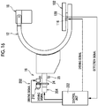
- control unit 126 of the radiography apparatus 100 controls the solenoid 116 provided at the other end of the arm 12.
- the control unit 126 transmits a driving signal to the solenoid 116 to energize the solenoid 116. Then, the movable iron core 116A illustrated in Fig. 8B is attracted by the solenoid 116 and the image receiving unit 102 is detachable from the arm 12.
- the control unit 126 de-energizes the solenoid 116.
- the insertion hole 118 of the image receiving unit 102 and the through hole 114 of the base 104 communicate with each other as illustrated in Fig. 8B . Therefore, the movable iron core 116A is inserted into the insertion hole 118 of the image receiving unit 102 to regulate the attachment and detachment of the image receiving unit 102 to and from the arm 12.
- control unit 126 controls the energization of the solenoid 116 to perform switching between a state in which the attachment and detachment of the image receiving unit 102 to and from the arm 12 is permitted and a state in which the attachment and detachment of the image receiving unit 102 to and from the arm 12 is regulated.
- control unit 126 determines whether or not the image receiving unit 102 is detached from the arm 12 on the basis of a detection signal from the photo sensor 120 provided in the arm 12.
- the control unit 126 receives an on signal as the detection signal from the photo sensor 120.
- the control unit 126 determines that the image receiving unit 102 is attached to the arm 12 while receiving the on signal from the photo sensor 120.
- the control unit 126 receives an off signal as the detection signal from the photo sensor 120.
- the control unit 126 determines that the image receiving unit 102 is detached from the arm 12 while receiving the off signal from the photo sensor 120.
- control unit 126 controls the friction mechanism 44 provided in the connection portion 14 in response to an operation command from the operation panel 30. That is, in a case in which a frictional force switching command is input through the operation panel 30, the control unit 126 transmits a driving signal to the clutch 66 of the friction mechanism 44 illustrated in Fig. 9 to energize the clutch 66, thereby switching the friction mechanism 44 to the first state, as in the first embodiment. In contrast, the control unit 126 de-energizes the clutch 66 to switch the friction mechanism 44 to the second state.
- control unit 126 controls the electromagnetic brake 124 provided in the connection portion 14. That is, the control unit 126 de-energizes the electromagnetic brake 124 to lock the rotation of the pulley shaft 48 and the pulley 54 with respect to the housing 124A of the electromagnetic brake 124 illustrated in Fig. 9 , thereby locking the orbital rotation of the arm 12 with respect to the track portion 22B.
- control unit 126 transmits a driving signal to the electromagnetic brake 124 to energize the electromagnetic brake 124. Then, the rotation of the pulley shaft 48 with respect to the housing 124A illustrated in Fig. 9 is unlocked. Thus, the rotation of the pulley 54 is unlocked to unlock the orbital rotation of the arm 12 with respect to the track portion 22B.
- Step S500 in a case in which the radiography apparatus 100 is turned on by the operation of a power switch (not illustrated) (Y in Step S500), the control unit 126 starts to control the radiography apparatus 100. In a case in which the control by the control unit 126 is started, it is possible to receive the input of the imaging conditions through the operation panel 30.
- Step S502 the control unit 126 determines whether or not the image receiving unit 102 is detached from the arm 12. In a case in which it is determined that the image receiving unit 102 is detached from the arm 12 (Y in Step S502), the control unit 126 switches the friction mechanism 44 to the first state (Step S504). That is, the clutch 66 of the friction mechanism 44 illustrated in Fig. 9 is energized to connect the housing 84 and the shaft fixing portion 86.
- Step S502 In a case in which it is determined in Step S502 that the image receiving unit 102 is attached to the arm 12 (N in Step S502), the control unit 126 switches the friction mechanism 44 to the second state (Step S506). That is, the clutch 66 of the friction mechanism 44 illustrated in Fig. 9 is de-energized to disconnect the housing 84 from the shaft fixing portion 86.
- Step S508 the control unit 126 determines whether or not the radiography apparatus 100 has been turned off by the operation of the power switch (not illustrated) by the operator. Then, in a case in which the radiography apparatus 100 has not been turned off (N in Step S508), the process returns to Step S502. On the other hand, in a case in which the radiography apparatus 100 has been turned off (Y in Step S508), the control unit 126 ends the control of the radiography apparatus 100.
- the friction mechanism 44 is connected to the first rotation mechanism 21 that rotates the arm 12 with respect to the connection portion 14, as in the radiography apparatus 10 according to the first embodiment. Therefore, the friction mechanism 44 can be switched between the first state and the second state to change a load due to the manual operation force of the arm 12.
- the image receiving unit 102 is attached to the arm 12 so as to be detachable.
- the arm 12 is likely to be inadvertently rotated due to a great change in weight balance during the detachment of the image receiving unit 102. Therefore, the friction mechanism 44 according to this embodiment is particularly effective for the radiography apparatus 100 in which the image receiving unit 102 is attachable to and detachable from the arm 12.
- the radiography apparatus 100 comprises the photo sensor 120 as an example of the attachment and detachment detection unit that detects whether or not the image receiving unit 102 is detached from the arm 12.
- the radiography apparatus 100 comprises the control unit 126 that performs control to switch the friction mechanism 44 to the first state in a case in which the photo sensor 120 detects that the image receiving unit 102 is detached from the arm 12 and to switch the friction mechanism 44 to the second state in a case in which the photo sensor 120 detects that the image receiving unit 102 is attached to the arm 12.
- the friction mechanism 44 is switched to the first state, that is, the frictional force acting on the arm 12 increases in operative association with the detachment of the image receiving unit 102. Therefore, even in a case in which the image receiving unit 102 is detached, it is possible to suppress the inadvertent rotation of the arm 12.
- the frictional force applied to the arm 12 by the friction mechanism 44 is set to a value that is greater than at least the maximum weight of the image receiving unit 102 that can be attached to the arm 12.
- the frictional force in the first state of the friction mechanism 44 is greater than the weight of the image receiving unit 102, a change in the weight balance of the arm 12 in a case in which the image receiving unit 102 is detached can be absorbed by the frictional force and it is possible to further suppress the inadvertent rotation of the arm 12.
- the radiography apparatus further comprises the electromagnetic brake 124 that locks the rotation of the arm 12 by the first rotation mechanism 21 and the electromagnetic brake 124 is connected to the pulley shaft 48.
- the electromagnetic brake 124 is provided in addition to the friction mechanism 44, the rotation of the arm 12 is locked by the electromagnetic brake 124 to prohibit the rotation of the arm 12 as necessary. Further, since the components of the first rotation mechanism 21 are connected to the electromagnetic brake 124, the size of each mechanism can be smaller than that in a case in which the first rotation mechanism 21 and the electromagnetic brake 124 are independently configured.
- a radiography apparatus according to a third embodiment of the present disclosure will be described with reference to Figs. 13 to 16 .
- the same configurations as those in the second embodiment are denoted by the same reference numerals and the description thereof will not be repeated. The description is focused on the differences between the second and third embodiments.
- the friction mechanism 44 and the electromagnetic brake 124 are connected to the pulley shaft 48 forming the first rotation mechanism 21.
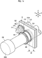
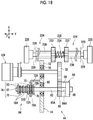
- a friction mechanism 202 and an electromagnetic brake 204 are connected to the support shaft 24 forming the second rotation mechanism 23.
- each of the friction mechanism 202 and the electromagnetic brake 204 is provided in the main body 16 of the radiography apparatus 200.
- a third gear 206 is fixed to an outer peripheral surface of the support shaft 24 so as to be coaxially rotatable and a fourth gear 208 is engaged with the third gear 206.
- the friction mechanism 202 includes a friction shaft 210, a frictional force generation unit 212 that is attached to the friction shaft 210 and generates a frictional force, and a clutch 214 that switches connection and disconnection between the support shaft 24 and the friction shaft 210.
- the friction shaft 210 is supported by a frame 216 of the main body 16 through a bearing (not illustrated). Further, the frictional force generation unit 212 is attached to one end of the friction shaft 210 in the axial direction. In this embodiment, the frictional force generation unit 212 is, for example, a rotary damper.
- the frictional force generation unit 212 comprises a rotor (not illustrated) that is fixed to one end of the friction shaft 210 in the axial direction, a housing 212A that accommodates the rotor, and a viscous body (not illustrated) that consists of oil filled between the rotor and the housing 212A.
- the friction shaft 210 In a case in which the friction shaft 210 is rotated, the rotor fixed to the friction shaft 210 is rotated in the housing 212A. In this case, a frictional force acts on the outer peripheral surface of the rotor in a direction opposite to the rotation direction due to the viscous resistance of the viscous body filled in the housing 212A. That is, the frictional force acts on the friction shaft 210 in the direction opposite to the rotation direction.
- the clutch 214 is attached to the other end of the friction shaft 210 in the axial direction.
- the clutch 214 is, for example, an electromagnetic clutch and has the same configuration as the clutch 66 according to the first and second embodiments. That is, the clutch 214 comprises a housing 218 that is fixed to the fourth gear 208 and a shaft fixing portion 220 that is fixed to the friction shaft 210.
- the housing 218 and the shaft fixing portion 220 are connected to each other (corresponding to the first state).
- the frictional force that acts on the friction shaft 210 in a direction opposite to the rotation direction acts on the support shaft 24 through the fourth gear 208 and the third gear 206.
- the frictional force acts on the arm 12 in a direction opposite to the rotation direction of the arm 12.
- An electromagnetic brake 204 is attached to the other end of the support shaft 24.
- the electromagnetic brake 204 has the same configuration as the electromagnetic brake 124 according to the second embodiment. That is, the electromagnetic brake 204 comprises a housing 204A that is fixed to the main body 16 so as not to be rotatable.
- the support shaft 24 is rotatably attached to the housing 204A through a rotor that is provided in the housing 204A.
- a control unit 222 controls the energization of the solenoid 116 to perform switching between a state in which the attachment and detachment of the image receiving unit 102 to and from the arm 12 is permitted and a state in which the attachment and detachment of the image receiving unit 102 to and from the arm 12 is regulated, as in the second embodiment.
- control unit 222 determines whether or not the image receiving unit 102 is detached from the arm 12 on the basis of a detection signal from the photo sensor 120 provided in the image receiving unit 102, as in the second embodiment.
- control unit 222 controls the friction mechanism 202 provided in the main body 16. That is, the control unit 222 transmits a driving signal to the clutch 214 of the friction mechanism 202 to energize the clutch 214, thereby switching the friction mechanism 202 to the first state. The control unit 222 de-energizes the clutch 214 to switch the friction mechanism 202 to the second state.
- control unit 222 controls the electromagnetic brake 204 provided in the main body 16. That is, the control unit 222 transmits a driving signal to the electromagnetic brake 204 to energize the electromagnetic brake as in the second embodiment. Then, the rotation of the support shaft 24 with respect to the housing 204A of the electromagnetic brake 204 illustrated in Fig. 14 is locked and the rotation of the arm 12 with respect to the bearing 25 is locked.
- the control unit 222 de-energizes the electromagnetic brake 204 to unlock the rotation of the support shaft 24 with respect to the housing 204A illustrated in Fig. 14 . Then, the axial rotation of the arm 12 with respect to the bearing 25 is unlocked.
- the control flow procedure of the control unit 222 according to this embodiment is the same as the control flow procedure of the control unit 126 according to the second embodiment. That is, as illustrated in Fig. 12 , in Step S502, the control unit 222 determines whether or not the image receiving unit 102 is detached from the arm 12. In a case in which it is determined that the image receiving unit 102 is detached from the arm 12 (Y in Step S502), the control unit 222 switches the friction mechanism 202 to the first state. In a case in which it is determined in Step S502 that the image receiving unit 102 is attached to the arm 12 (N in Step S502), the control unit 222 switches the friction mechanism 202 to the second state.
- the radiography apparatus 200 comprises the second rotation mechanism 23 that rotates the arm 12 about the axis with respect to the main body 16 and the friction mechanism 202 that applies a frictional force to the arm 12 in a direction opposite to the direction in which the arm 12 is rotated by the second rotation mechanism 23. Therefore, similarly to the radiography apparatus 100 according to the second embodiment, the friction mechanism 202 is switched between the first state and the second state to change a load due to the manual operation force of the arm 12.
- the friction mechanism 202 is connected to the support shaft 24 forming the second rotation mechanism 23.
- the components of the second rotation mechanism 23 and the components of the friction mechanism 202 are operatively associated with each other. Therefore, the size of each mechanism can be smaller than that in a case in which the second rotation mechanism 23 and the friction mechanism 202 are independently configured.
- the radiography apparatus further comprises the electromagnetic brake 204 that locks the rotation of the arm 12 by the second rotation mechanism 23.
- the electromagnetic brake 204 is connected to the support shaft 24.
- the electromagnetic brake 204 is provided in addition to the friction mechanism 202, the rotation of the arm 12 is locked by the electromagnetic brake 204. Therefore, it is possible to prohibit the rotation of the arm 12 as necessary. Further, the components of the second rotation mechanism 23 are connected to the electromagnetic brake 204. Therefore, the size of each mechanism can be smaller than that in a case in which the second rotation mechanism 23 and the electromagnetic brake 204 are independently configured.
- the friction mechanism 44 is connected to the first rotation mechanism 21 that orbitally rotates the arm 12.
- the friction mechanism 44 may be connected to the second rotation mechanism 23 that rotates the arm 12 about the axis.
- the friction mechanism 44 may be connected to each of the first rotation mechanism 21 and the second rotation mechanism 23.
- the friction mechanism 44 or 202 is connected to the first rotation mechanism 21 or the second rotation mechanism 23, and the frictional force of the friction mechanism 44 or 202 is applied to the arm 12 through the first rotation mechanism 21 or the second rotation mechanism 23.
- the friction mechanism 44 or 202 may be attached to the arm 12 such that the frictional force of the friction mechanism 44 or 202 is directly applied to the arm 12.
- the electromagnetic brake 124 or 204 is connected to the first rotation mechanism 21 or the second rotation mechanism 23, and the first rotation mechanism 21 or the second rotation mechanism 23 is locked to lock the rotation of the arm 12.
- the electromagnetic brake 124 or 204 may be attached to the arm 12 and the rotation of the arm 12 may be directly locked by the electromagnetic brake 124 or 204.
- a pair of operation handles 224 may be provided in the connection portion 14 of the radiography apparatus 100 according to the second embodiment.
- the pair of operation handles 224 are provided independently of the arm 12 illustrated in Fig. 11 and are manually operated to input an operation force for displacing the arm 12 to the first rotation mechanism 21.
- the pair of operation handles 224 have the same configuration and comprise a grip portion 226 and a handle shaft 228 that is fixed to the grip portion 226 so as to be coaxially rotatable.
- the grip portion 226 is a portion which the operator grips with hands to operate the operation handle 224.
- the grip portion 226 has a cylindrical shape that has a larger outer diameter than the handle shaft 228.
- the handle shaft 228 is disposed in parallel to the pulley shaft 48 forming the first rotation mechanism 21 and is supported by a side wall 229 of the connection portion 14 through a bearing (not illustrated) so as to be rotatable and movable in the axial direction.
- the handle shafts 228 of the pair of operation handles 224 are disposed on the same axis line.
- one end of the handle shaft 228 of the operation handle 224 is exposed from the side wall 229 of the connection portion 14 to the outside of the connection portion 14.
- the grip portion 226 is provided at the one end of the handle shaft 228. That is, the grip portions 226 of the pair of operation handles 224 are provided on both side surfaces of the connection portion 14 so as to protrude. Therefore, the operator can grip the grip portions 226 from both sides of the connection portion 14 and operate the operation handle 224.
- a switching mechanism 230 for switching between a valid state in which the input of an operation force from the operation handle 224 to the first rotation mechanism 21 is validated and an invalid state in which the input is invalidated is provided at the other end of the handle shaft 228 located inside the connection portion 14.
- the switching mechanism 230 comprises a pair of gears 232 that are fixed to the other ends of the pair of handle shafts 228 in the axial direction so as to be coaxially rotatable and a biasing member 234 that consists of, for example, a coil spring.
- the pair of gears 232 face each other with a gap therebetween in the axial direction of the handle shaft 228.
- the first gear 58 fixed to the pulley shaft 48 is located between the pair of gears 232 in the axial direction of the handle shaft 228. In a case in which the gears 232 are moved to the other end of the handle shaft 228 in the axial direction, the first gear 58 is engaged with the gears 232.
- the biasing member 234 is provided between the pair of gears 232.
- the gears 232 are biased by the biasing member 234 in a direction in which they become further away from each other, that is, to one end of the shaft portion in the axial direction.
- a spacer 236 is provided between the gear 232 and the side wall 229 of the connection portion 14.
- the spacer 236 is a cylindrical member into which the handle shaft 228 is inserted. The spacer 236 regulates the movement of the gear 232 to the side wall 229, that is, the movement of the gear 232 to one end of the handle shaft 228 in the axial direction.
- the operator grips one of the pair of grips 226, which are provided on both side surfaces of the connection portion 14 so as to protrude, with the hand and pushes the grip portion 226 to the inside of the connection portion 14, that is, the other end of the handle shaft 228 in the axial direction.
- the gear 232 of the switching mechanism 230 fixed to the other end of the handle shaft 228 in the axial direction is biased to one end of the handle shaft 228 in the axial direction by the biasing member 234. Therefore, the operator pushes the grip portion 226 against the biasing force of the biasing member 234.
- the grip portion 226 of the other operation handle 224 is pushed to engage the other gear 232 with the first gear 58.
- the other operation handle 224 can be operated to rotate the arm 12.
- the operation handle 224 makes it possible to operate the arm 12 without directly operating the arm 12. Further, since the arm 12 is displaced through the first rotation mechanism 21, the amount of displacement of the arm 12 can be adjusted more easily than that in a case in which the arm 12 is directly operated.
- the gear ratio of the first rotation mechanism 21 can be set to adjust the relationship between the amount of rotation of the operation handle 224 and the amount of rotation of the arm 12. Therefore, the setting of reducing the amount of rotation of the arm 12 with respect to the amount of rotation of the operation handle 224 is relatively simple.
- the operation handle 224 makes it easy to finely adjust the amount of rotation of the arm 12.
- the arm 12 holding the irradiation unit 18 and the image receiving unit 102 is used during surgery.
- the operation handle 224 is provided independently of the arm 12, which makes it possible to separate an operation part operated by the operator from an operation part operated by the assistant. Therefore, the following method can also be used: the assistant rotates the arm 12 while avoiding the operation part contaminated by contact with the operator.
- the displacement mechanism for displacing the arm 12 is the rotation mechanism (the first rotation mechanism 21 and the second rotation mechanism 23) that rotates the arm 12.
- the displacement mechanism for displacing the arm 12 is not limited to the rotation mechanism and may be, for example, a slide mechanism 240 that slides the arm as illustrated in Fig. 19 .
- the slide mechanism 240 comprises a rack 242 that has one end fixed to the arm 12 and a pinion 244 that is provided in the main body 16.
- the rack 242 has a plurality of teeth 242A formed on the lower surface and is attached to the main body 16 so as to be movable in the horizontal direction (X direction).
- the pinion 244 is a circular gear that has a plurality of teeth 244A formed on the outer peripheral surface and is fixed to the main body 16 so as to be rotatable about the axis.
- the teeth 244A of the pinion 244 are engaged with the teeth 242A of the rack 242 such that the rack 242 and the pinion 244 are operatively associated with each other. Therefore, in a case in which the arm 12 is manually slid with respect to the main body 16, the rack 242 slides in the direction of an arrow R and the pinion 244 engaged with the rack 242 is rotated.
- a gear (not illustrated) is engaged with the pinion 244.
- the friction mechanism 44 is connected to the gear.
- the friction mechanism 44 has the same configuration as that in the first embodiment and can be switched between a connected state to the gear and a disconnected state from the gear by the clutch 66 (see Fig. 6 ).
- the image receiving unit 102 attached to the arm 12 so as to be detachable is a detector that is provided in the housing so as not to be detachable.
- an image receiving unit 246 that is attached to the arm 12 so as to be detachable may include a detector 248 and an accommodation portion 250.
- the detector 248 is accommodated in the accommodation portion 250 so as to be detachable and the accommodation portion 250 is attached to the arm 12 so as to be detachable.
- the detector 248 being attachable to and detachable from the accommodation portion 250 is synonymous with the detector 248 being attachable to and detachable from the arm 12. Therefore, this configuration makes it possible to change the size of the detector 248 attached to the arm 12.
- the accommodation portion 250 can also be attached to and detached from the arm 12. Therefore, in a case in which the size of the detector 248 is changed, it is easy to maintain the weight balance of the arm 12.
- the weights of the irradiation unit 18 (see Fig. 11 ) and the image receiving unit 246 held at both ends of the C-arm illustrated as an example of the arm 12 are balanced to prevent inadvertent orbital rotation and to keep the arm at any rotational position.
- the center of the orbital rotation of the arm 12 (aligned with the axis line M in Fig. 2A ) is aligned with the center of gravity of the entire arm 12 including the irradiation unit 18 and the image receiving unit 246. Therefore, the arm 12 is kept at any rotational position by the effect of the weight balance of the arm 12.
- the accommodation portion 250 is attachable to and detachable from the arm 12, which makes it possible to compensate a change in the weight of the detector 248 with a change in the weight of the accommodation portion 250.
- the accommodation portion 250 for example, a plurality of types of accommodation portions having different weights are prepared in which, for example, a weight adjusting ballast is changed to change the weight. The plurality of types of accommodation portions 250 are appropriately used to compensate for a weight change caused by a change in the size of the detector 248.
- the accommodation portion 250 is changed according to the size change to maintain the weight balance between the irradiation unit 18 and the image receiving unit 246 and to align the center of gravity of the arm 12 with the center of the orbital rotation.
- the detector 248 forming the image receiving unit 246 consists of, for example, a flat panel detector and receives the radiation which has been emitted from the irradiation unit 18 illustrated in Fig. 1 and transmitted through the subject H with an image receiving surface 248A to detect a radiographic image of the subject H.
- the detector 248 functions as a portable electronic cassette.
- the accommodation portion 250 forming the image receiving unit 246 is a box with a flat rectangular parallelepiped shape and has a fitting concave portion 252 formed in the lower surface and an accommodation concave portion 254 that accommodates the detector 248.
- the fitting concave portion 252 has the same configuration as the fitting concave portion 108 formed in the lower surface of the image receiving unit 102 according to the second embodiment.
- the fitting convex portion 106 provided at the other end of the arm 12 is fitted to the fitting concave portion 252. Therefore, the accommodation portion 250 is attached to the arm 12 so as to be detachable.
- the arm 12 is provided with a solenoid 116 that regulates the attachment and detachment of the accommodation portion 250 to and from the arm 12 and a photo sensor 120 as an attachment and detachment detection unit.
- the photo sensor 120 detects whether or not the accommodation portion 250 is detached from the arm 12, that is, whether or not both the accommodation portion 250 and the detector 248 forming the image receiving unit 246 are detached from the arm 12.
- an opening 254A for accommodating the detector 248 in the accommodation concave portion 254 is formed in one of four side surfaces of the accommodation portion 250.
- an opening 254B with a square shape which communicates with the accommodation concave portion 254 is formed in the upper surface of the accommodation portion 250 which faces the irradiation opening 34A (see Fig. 1 ) of the irradiation unit 18.
- an image receiving surface 248A of the detector 248 is exposed through an opening 254B that is formed in the upper surface of the accommodation portion 250 as illustrated in Fig. 20B . Therefore, even in a state in which the detector 248 is attached to the accommodation portion 250, that is, the arm 12, the radiation emitted from the irradiation unit 18 (see Fig. 1 ) can be received by the image receiving surface 248A of the detector 248.
- the accommodation portion 250 is provided with a photo sensor 256 that detects whether or not the detector 248 is detached from the accommodation portion 250.
- the photo sensor 256 is provided on a side surface of the accommodation portion 250 which is opposite to the side surface in which the opening 254A is formed in the accommodation concave portion 254.
- the photo sensor 256 has the same configuration as the photo sensor 120 and detects a change in the amount of light which has been emitted from a light emitting element and then received by a light receiving element to detect whether or not the detector 248 is in the accommodation concave portion 254.
- the sensor that detects whether or not the detector 248 is detached from the accommodation portion 250 is not limited to the photo sensor 256 and may be, for example, a contact sensor using a piezoelectric element or a microswitch.
- an attachment and detachment regulation mechanism (not illustrated) that fixes the detector 248 in the accommodation concave portion 254 to prevent the detector 248 from falling off and releases the fixation may be provided in the accommodation concave portion 254.
- a change in the weight balance of the arm 12 is smaller than that in a state in which both the accommodation portion 250 and the detector 248 are detached from the arm 12.
- the friction mechanism 44 is switched to the first state in a case in which the photo sensor 120 detects that the accommodation portion 250 is attached to the arm 12 and the photo sensor 256 detects that the detector 248 is detached from the accommodation portion 250. That is, the frictional force acting on the arm 12 is increased in operative association with the detachment of the detector 248 to suppress the inadvertent rotation of the arm 12 in a case in which the detector 248 is detached.
- the frictional force of the friction mechanism 44 may be changed in three steps of a case in which the image receiving unit 246 (that is, the detector 248 and the accommodation portion 250) is attached to the arm 12, a case in which only the accommodation portion 250 is attached to the arm 12, and a case in which the image receiving unit 246 is not attached to the arm 12. In this case, it is possible to adjust the frictional force acting on the arm 12 according to the magnitude of a change in the weight balance of the arm 12.
- the arm 12 can be displaced (rotated) by only a manual operation.
- the arm 12 may be rotated by an electric operation, or the manual operation and the electric operation may be switched.
- the first rotation mechanism 21 is configured by the track portion 22B and the pulley shaft 48 provided in the connection portion 14, the fitting portion 22A formed in the arm 12, and the belt 46 fixed to both ends of the arm 12.
- the first rotation mechanism 21 may have any configuration as long as it can orbitally rotate the arm 12 with respect to the connection portion 14 as a support portion.
- the first rotation mechanism may be configured by a pinion that is fixed to the rotation shaft (not illustrated) provided in the connection portion 14 so as to be coaxially rotatable and a rack (not illustrated) which is provided on the outer peripheral surface of the arm 12 and in which a plurality of teeth engaged with the pinion are formed.
- the "second state” of the friction mechanism 44 is the state in which the frictional force of the friction shaft 62 does not act on the arm 12 (the state in which the acting frictional force is 0).
- the "second state” of the friction mechanism 44 may be a state in which at least the frictional force acting on the arm 12 is less than that in the "first state” and is not limited to the state in which the frictional force is 0.
- the friction mechanism 44 may be switched to the "second state” by adjusting the tightening force of the nut 82 illustrated in Fig. 7 such that the frictional force acting on the friction shaft 62 is less than that in the "first state".
- the frictional force in a case in which the friction mechanism 44 is in the "first state” is greater than the maximum weight of the image receiving unit 102 that can be attached to the arm 12.
- the frictional force in a case in which the friction mechanism 44 is in the "first state” may be less than the maximum weight of the image receiving unit 102 that can be attached to the arm 12.
- the arm 12 is rotated in a case in which the image receiving unit 102 is detached from the arm 12.
- the difference between the frictional force and the weight is small, it is possible to reduce the rotational momentum. Even in this case, the effect of reducing the rotational momentum of the arm 12 is obtained.
- the electromagnetic clutch is used as the clutch 66 forming the friction mechanism 44.
- the clutch 66 is not limited to the electromagnetic clutch and other known clutches including a powder clutch may be used.
- the arm (C-arm) that can be orbitally rotated and can be rotated about the axis has been described as an example of the arm 12.
- an arm for example, a U-arm having a U-shape in a side view
- the U-arm can hold, for example, the irradiation unit 18 and the image receiving unit 20 or 102 in a posture in which they face each other.
- X-rays have been described as an example of the radiation.
- the present disclosure is not limited to the X-rays.
- ⁇ -rays may be used.
- the following various processors can be used as a hardware structure of processing units performing various processes, such as the control unit 28.
- the various processors include, for example, a CPU which is a general-purpose processor executing software to function as various processing units as described above, a programmable logic device (PLD), such as a field programmable gate array (FPGA), which is a processor whose circuit configuration can be changed after manufacture, and a dedicated electric circuit, such as an application-specific integrated circuit (ASIC), which is a processor having a dedicated circuit configuration designed to perform a specific process.
- PLD programmable logic device
- FPGA field programmable gate array
- ASIC application-specific integrated circuit
- One processing unit may be configured by one of the various processors or a combination of two or more processors of the same type or different types (for example, a combination of a plurality of FPGAs and/or a combination of a CPU and an FPGA). Further, a plurality of processing units may be configured by one processor.
- a first example of the configuration in which a plurality of processing units are configured by one processor is an aspect in which one processor is configured by a combination of one or more CPUs and software and functions as a plurality of processing units.
- a second example of the configuration is an aspect in which a processor that implements the functions of the entire system including a plurality of processing units using one integrated circuit (IC) chip is used.
- IC integrated circuit
- a representative example of this aspect is a system-on-chip (SoC).
- SoC system-on-chip
- various processing units are configured by using one or more of the various processors as the hardware structure.
- circuitry obtained by combining circuit elements, such as semiconductor elements, can be used as the hardware structure of the various processors.
Landscapes
- Health & Medical Sciences (AREA)
- Life Sciences & Earth Sciences (AREA)
- Medical Informatics (AREA)
- Engineering & Computer Science (AREA)
- Radiology & Medical Imaging (AREA)
- Biomedical Technology (AREA)
- Biophysics (AREA)
- Nuclear Medicine, Radiotherapy & Molecular Imaging (AREA)
- Optics & Photonics (AREA)
- Pathology (AREA)
- Physics & Mathematics (AREA)
- High Energy & Nuclear Physics (AREA)
- Heart & Thoracic Surgery (AREA)
- Molecular Biology (AREA)
- Surgery (AREA)
- Animal Behavior & Ethology (AREA)
- General Health & Medical Sciences (AREA)
- Public Health (AREA)
- Veterinary Medicine (AREA)
- Apparatus For Radiation Diagnosis (AREA)
Abstract
Description
- The present disclosure relates to a radiography apparatus.
- A radiography apparatus (X-ray apparatus) has been known which includes an arm having two ends. An irradiation unit (X-ray tube) that emits radiation is provided at one end of the arm. An image receiving unit (image receiving device) that receives the radiation emitted from the irradiation unit is provided at the other end of the arm. This arm is supported so as to be rotatable with respect to a main body of the radiography apparatus. The arm is rotated such that the irradiation unit and the image receiving unit can be positioned in any posture around a subject while maintaining a relative position. In addition, in a radiography apparatus disclosed in
JP1994-070918A JP-H06-070918A - In a case in which the arm is manually operated, the load of an operation force may be small or large according to circumstances. For example, a case in which the radiography apparatus is used during surgery is considered. In this case, it is preferable that the load of the operation force of the arm is small in a positioning stage before surgery. After the surgery is started, it is preferable that the arm is not inadvertently rotated due to contact with a person.
- In particular, in the case of an arm that holds both the irradiation unit and the image receiving unit, the weight of the arm is greater than that of an arm that holds only the irradiation unit. Therefore, there is a great need to reduce the load of the operation force due to a manual operation. In a case in which the load of the operation force is always small, inadvertent rotation is likely to occur, which is not preferable.
JP1994-070918A JP-H06-070918A - An object of the technology according to the present disclosure is to provide a radiography apparatus that can change a load due to a manual operation force of an arm.
- According to a first aspect of the present disclosure, there is provided a radiography apparatus comprising: an irradiation unit that emits radiation; an arm that is capable of holding the irradiation unit and an image receiving unit that receives the radiation, which has been emitted from the irradiation unit and transmitted through a subject, in a facing posture; a support portion that supports the arm; a displacement mechanism that displaces the arm with respect to the support portion; and a friction mechanism that is switchable between a first state in which a frictional force is applied to the arm in a direction opposite to a direction in which the arm is displaced and a second state in which the frictional force applied to the arm is less than the frictional force in the first state.
- According to the above-mentioned configuration, the radiography apparatus comprises the displacement mechanism that displaces the arm and the friction mechanism that is switchable between the first state in which the frictional force is applied to the arm in the direction opposite to the direction in which the arm is displaced and the second state in which the frictional force applied to the arm is less than that in the first state. Therefore, the friction mechanism is switched between the first state and the second state to change a load due to the manual operation force of the arm.
- According to a second aspect of the present disclosure, the radiography apparatus according to the first aspect may further comprise an operation portion that switches the friction mechanism between the first state and the second state.
- According to the above-mentioned configuration, the operator can optionally switch the frictional force. For example, before surgery, it is possible to reduce the frictional force such that positioning is performed with a small force. During surgery, it is possible to increase the frictional force in order to prevent the arm from being inadvertently rotated due to the application of an unintended external force to the arm such as the collision of the operator with the arm.
- According to a third aspect of the present disclosure, in the radiography apparatus according to the first aspect or the second aspect, the arm may be displaced by only a manual operation.
- According to the above-mentioned configuration, the arm is not displaced by an electromotive force, but can be displaced by only a manual operation. Therefore, it is possible to reduce the size and weight of the entire radiography apparatus. In many cases, a large-sized radiography apparatus includes a mechanism that electrically displaces the arm. In general, in the large-sized apparatus, the operation force of the arm is controlled through a complicated mechanism such as an electric mechanism.
- Here, the friction mechanism according to the technology of the present disclosure can switch the operation force of the arm with a relatively simple structure even in a case in which the arm is displaced by only a manual operation to reduce the size and weight of the apparatus. Therefore, the technology of the present disclosure is particularly effective for an apparatus with a small size and weight in which the arm is displaced by only a manual operation.
- According to a fourth aspect of the present disclosure, in the radiography apparatus according to any one of the first to third aspects, the displacement mechanism may be a rotation mechanism that rotates the arm.
- According to the above-mentioned configuration, a load is applied in the rotation operation of rotating the arm, as compared to an operation of sliding the arm in the horizontal direction. Therefore, this configuration is particularly effective in a case in which the friction mechanism capable of switching the frictional force is combined with the rotation mechanism.
- According to a fifth aspect of the present disclosure, in the radiography apparatus according to the fourth aspect, the image receiving unit may be attachable to and detachable from the arm.
- According to the above-mentioned configuration, in a case in which the arm is rotated and the image receiving unit is attachable and detachable, a weight balance changes greatly during the detachment of the image receiving unit. As a result, inadvertent rotation is likely to occur. Therefore, for example, in a case in which the image receiving unit is detached, the frictional force is increased to suppress inadvertent rotation.
- According to a sixth aspect of the present disclosure, the radiography apparatus according to the fifth aspect may further comprise: an attachment and detachment detection unit that detects whether or not the image receiving unit is detached from the arm; and a control unit that performs control to switch the friction mechanism to the first state in a case in which the attachment and detachment detection unit detects that the image receiving unit is detached from the arm and to switch the friction mechanism to the second state in a case in which the attachment and detachment detection unit detects that the image receiving unit is attached to the arm.
- In a case in which the image receiving unit is detached from the arm, the weight balance of the arm may change and the arm may be inadvertently rotated. Here, according to the above-mentioned configuration, the frictional force is increased in operative association with the detachment of the image receiving unit. Therefore, it is possible to suppress the inadvertent rotation of the arm even in a case in which the image receiving unit is detached.
- According to a seventh aspect of the present disclosure, in the radiography apparatus according to the sixth aspect, the frictional force in the first state may be greater than a maximum weight of the image receiving unit that is capable of being attached to the arm.
- According to the above-mentioned configuration, since the frictional force in the first state is greater than the weight of the image receiving unit, a change in the weight balance of the arm in a case in which the image receiving unit is detached can be absorbed by the frictional force and it is possible to further suppress the inadvertent rotation of the arm.
- According to an eighth aspect of the present disclosure, the radiography apparatus according to any one of the fourth to seventh aspects may further comprise an electromagnetic brake that locks the rotation of the arm by the rotation mechanism.
- According to the above-mentioned configuration, the radiography apparatus includes the electromagnetic brake that locks the rotation of the arm in addition to the friction mechanism. Therefore, the electromagnetic brake locks the rotation of the arm to prohibit the rotation of the arm as necessary.
- According to a ninth aspect of the present disclosure, in the radiography apparatus according to any one of the fourth to eighth aspects, the rotation mechanism may have a rotation shaft that is rotated with the rotation of the arm and the friction mechanism may comprise a friction shaft, a frictional force generation unit that is attached to the friction shaft and generates a frictional force, and a clutch that switches connection and disconnection between the rotation shaft and the friction shaft to switch between the first state and the second state.
- According to the above-mentioned configuration, the components of the rotation mechanism and the components of the friction mechanism are operatively associated with each other to reduce the size of each mechanism, as compared to a case in which the rotation mechanism and the friction mechanism are independently configured.
- According to a tenth aspect of the present disclosure, in the radiography apparatus according to the eighth aspect or the ninth aspect citing the eighth aspect, the rotation mechanism may have a rotation shaft that is rotated with the rotation of the arm and the electromagnetic brake may be connected to the rotation shaft.
- According to the above-mentioned configuration, the components of the rotation mechanism and the electromagnetic brake are connected to each other to reduce the size of each mechanism, as compared to a case in which the rotation mechanism and the electromagnetic brake are independently configured.
- According to an eleventh aspect of the present disclosure, in the radiography apparatus according to the ninth aspect or the tenth aspect, the arm may have an arc shape in a side view. The rotation mechanism may include a first rotation mechanism comprising a track portion that is provided in the support portion and supports the arm so as to be movable along the arc shape, a fitting portion that is formed in an outer peripheral portion of the arm and is fitted to the track portion, and a first rotation shaft as the rotation shaft. The arm may be moved with respect to the track portion to be orbitally rotated about a center of the arc shape as a rotation center.
- According to the above-mentioned configuration, since the arm can be orbitally rotated along the arc shape, the irradiation unit and the image receiving unit can be rotated about the body axis of the subject.
- According to a twelfth aspect of the present disclosure, in the radiography apparatus according to the eleventh aspect citing the ninth aspect, the rotation mechanism may further include a belt that has one end fixed to an end of the arm at which the irradiation unit is provided and the other end fixed to an end f the arm at which the image receiving unit is provided. The belt may be wound around the first rotation shaft.
- According to the above-mentioned configuration, it is possible to operatively associate the components of the rotation mechanism with the components of the friction mechanism even in orbital rotation and to reduce the size of each mechanism, as compared to a case in which the rotation mechanism and the friction mechanism are independently configured.
- Further, as a modification example of the orbital rotation mechanism, a rack and pinion system or a system in which a chain and a sprocket are combined are considered instead of the belt. However, in a case in which the belt is used, the weight of the apparatus can be less than that in these systems.
- According to a thirteenth aspect of the present disclosure, in the radiography apparatus according to any one of the ninth to twelfth aspects, the rotation mechanism may include a second rotation mechanism comprising a second rotation shaft as the rotation shaft that has one end fixed to the arm and a bearing that is provided in the support portion. The arm may be rotated about the second rotation shaft with respect to the bearing to reverse positions of the irradiation unit and the image receiving unit with respect to the subject.
- According to the above-mentioned configuration, since the arm is rotatable about the rotation shaft, it is possible to switch between an overtube posture in which the irradiation unit is disposed above the image receiving unit and an undertube posture in which the irradiation unit is disposed below the image receiving unit.
- According to a fourteenth aspect of the present disclosure, the radiography apparatus according to any one of the first to thirteenth aspects may further comprise an operation handle that is provided independently of the arm and is manually operated to input an operation force for displacing the arm to the displacement mechanism.
- According to the above-mentioned configuration, the operation handle makes it possible to operate the arm, without directly operating the arm. Further, since the arm is displaced through the displacement mechanism, the amount of displacement of the arm can be adjusted more easily than that in a case in which the arm is directly operated.
- That is, the gear ratio of the displacement mechanism can be set to adjust the relationship between the amount of operation of the operation handle and the amount of displacement of the arm. Therefore, the setting of reducing the amount of displacement of the arm with respect to the amount of displacement of the operation handle is relatively simple. The operation handle makes it easy to finely adjust the amount of displacement of the arm.
- In many cases, the arm that holds the irradiation unit and the image receiving unit is used during surgery. Since the operation handle is provided independently of the arm, it is possible to separate an operation part operated by the operator from an operation part operated by the assistant. Therefore, the following method can also be used: the assistant rotates the arm while avoiding the operation part contaminated by contact with the operator.
- According to the technology of the present disclosure, it is possible to change a load due to the manual operation force of the arm.
-
-
Fig. 1 is an overall perspective view illustrating a radiography apparatus according to a first embodiment. -
Fig. 2A is a side view illustrating the radiography apparatus according to the first embodiment. -
Fig. 2B is a side view illustrating a state in which an arm of the radiography apparatus illustrated inFig. 2A is rotated in the direction of an arrow M1. -
Fig. 2C is a side view illustrating a state in which the arm of the radiography apparatus illustrated inFig. 2A is rotated in the direction of an arrow M2. -
Fig. 3A is a front view illustrating the radiography apparatus according to the first embodiment. -
Fig. 3B is a front view illustrating a state in which the arm of the radiography apparatus illustrated inFig. 3A is rotated in the direction of an arrow N1. -
Fig. 3C is a front view illustrating a state in which the arm of the radiography apparatus illustrated inFig. 3A is rotated 180° in the direction of an arrow N2. -
Fig. 4 is an overall side view illustrating a friction mechanism of the radiography apparatus according to the first embodiment. -
Fig. 5 is a cross-sectional view taken along the line A-A ofFig. 4 . -
Fig. 6 is a perspective view illustrating the friction mechanism of the radiography apparatus according to the first embodiment. -
Fig. 7 is a plan view illustrating the friction mechanism illustrated inFig. 6 . -
Fig. 8A is a partial perspective view illustrating an image receiving unit of a radiography apparatus according to a second embodiment. -
Fig. 8B is a cross-sectional view illustrating the image receiving unit illustrated inFig. 8A . -
Fig. 9 is a perspective view illustrating a friction mechanism and an electromagnetic brake of the radiography apparatus according to the second embodiment. -
Fig. 10 is a plan view illustrating the friction mechanism and the electromagnetic brake illustrated inFig. 9 . -
Fig. 11 is a block diagram illustrating a functional configuration of a control unit of the radiography apparatus according to the second embodiment. -
Fig. 12 is a flowchart illustrating a processing procedure of the control unit of the radiography apparatus according to the second embodiment. -
Fig. 13 is an overall side view illustrating a friction mechanism of a radiography apparatus according to a third embodiment. -
Fig. 14 is a perspective view illustrating the friction mechanism of the radiography apparatus according to the third embodiment. -
Fig. 15 is a plan view illustrating the friction mechanism illustrated inFig. 14 . -
Fig. 16 is a block diagram illustrating a functional configuration of a control unit of the radiography apparatus according to the third embodiment. -
Fig. 17 is a perspective view illustrating an operation handle of a radiography apparatus according to a modification example. -
Fig. 18 is a plan view illustrating the operation handle illustrated inFig. 17 . -
Fig. 19 is a side view illustrating a displacement mechanism of a radiography apparatus according to a modification example. -
Fig. 20A is a partial perspective view illustrating an image receiving unit of a radiography apparatus according to a modification example. -
Fig. 20B is a cross-sectional view illustrating the image receiving unit illustrated inFig. 20A . - Hereinafter, radiography apparatuses according to first to third embodiments of the present disclosure will be sequentially described with reference to the drawings. In the drawings, an arrow X indicates the front-rear direction of the radiography apparatus, an arrow Y indicates the width direction of the radiography apparatus, and an arrow Z indicates the vertical direction.
- First, a radiography apparatus according to the first embodiment of the present disclosure will be described with reference to
Figs. 1 to 7 . - A
radiography apparatus 10 according to this embodiment illustrated inFig. 1 is an apparatus that captures a radiographic image of a subject H. Theradiography apparatus 10 can capture, for example, moving images and still images of the subject H. The capture of the moving image is performed, for example, in a case in which a treatment target part of the subject H is displayed as a moving image during surgery (also referred to as fluoroscopy). In the capture of the moving image, for example, the moving image of the subject H is displayed on a monitor (not illustrated) that is provided separately from theradiography apparatus 10. Of course, data of the captured moving image may be stored in a memory of theradiography apparatus 10. In addition, in the case of the capture of the still image, the captured still image may be displayed on the monitor or may be stored in the memory of theradiography apparatus 10. - As illustrated in
Fig. 1 , theradiography apparatus 10 includes an arm 12 (referred to as a C-arm or the like) having a C-shape (an arc shape) in a side view and amain body 16 to which aconnection portion 14 is attached. Hereinafter, it is assumed that the side of theradiography apparatus 10 on which thearm 12 is provided is the front side of theradiography apparatus 10 and the side on which themain body 16 is provided is the rear side of theradiography apparatus 10. - The
arm 12 has two ends. Anirradiation unit 18 is provided at one end of thearm 12 and animage receiving unit 20 is provided at the other end. Thearm 12 can hold theirradiation unit 18 and theimage receiving unit 20 in a posture in which they face each other. A space, into which the subject H and a bed S on which the subject H lies supine can be inserted, is ensured between theirradiation unit 18 and theimage receiving unit 20. In the following description, in some cases, in a side view of the arm 12 (as viewed from the Y direction inFig. 1 ), a direction in which theirradiation unit 18 and theimage receiving unit 20 are provided on the basis of thearm 12 is referred to as the front side of thearm 12 and the side of thearm 12 is referred to as the rear side of thearm 12. - The
arm 12 can be rotated by a manual operation. Specifically, as illustrated inFig. 2A , thearm 12 can be orbitally rotated about an axis line M (an axis line parallel to the Y axis) with respect to theconnection portion 14 by afirst rotation mechanism 21 which is an example of a displacement mechanism. Further, thearm 12 can be rotated about an axis line N (an axis line parallel to the X-axis) with respect to themain body 16 by asecond rotation mechanism 23 which is an example of the displacement mechanism. In this embodiment, theconnection portion 14 or themain body 16 corresponds to a "support portion" that supports thearm 12. - The
first rotation mechanism 21 comprises atrack portion 22B that is provided in theconnection portion 14 and afitting portion 22A that is formed on an outer peripheral surface of thearm 12 and is fitted to thetrack portion 22B. Thefirst rotation mechanism 21 further comprises apulley shaft 48 as a first rotation shaft, which will be described below, and abelt 46. - The
fitting portion 22A has an arc shape following the shape of thearm 12. Thetrack portion 22B has an arc shape that has the same radius as the arc of thearm 12 and supports thearm 12 so as to be movable along the arc shape. As illustrated inFig. 5 , thetrack portion 22B has, for example, a groove shape and thefitting portion 22A having a convex shape is fitted to thetrack portion 22B. A roller (not illustrated) that assists the sliding of thefitting portion 22A with respect to thetrack portion 22B is interposed between thetrack portion 22B and thefitting portion 22A. - The
fitting portion 22A formed in thearm 12 slides along thetrack portion 22B formed in theconnection portion 14 such that thearm 12 can be orbitally rotated about the axis line M at the center of the arc of thearm 12 as a rotation center with respect to theconnection portion 14 and themain body 16. - That is, as illustrated in
Figs. 2B and2C , it is possible to orbitally rotate thearm 12 about the axis line M in the direction of an arrow M1 (counterclockwise inFig. 2B ) and the direction of an arrow M2 (clockwise inFig. 2C ). Therefore, it is possible to rotate theirradiation unit 18 and theimage receiving unit 20 provided at both ends of thearm 12 about the body axis (an axis parallel to the Y axis) of the subject H (seeFig. 1 ). - As illustrated in
Fig. 2A , thesecond rotation mechanism 23 comprises asupport shaft 24 as a second rotation shaft, one end of which is fixed to thearm 12, and abearing 25 which is provided in themain body 16. Thesupport shaft 24 extends in the front-rear direction (X direction) of theradiography apparatus 10 and has the other end that is supported by themain body 16 through thebearing 25. - The
support shaft 24 is rotated about the axis line N with respect to thebearing 25 such that thearm 12 and theconnection portion 14 are rotatable about the axis line N of thesupport shaft 24 with respect to themain body 16 as illustrated inFigs. 3A to 3C . - That is, as illustrated in
Figs. 3B and3C , it is possible to rotate thearm 12 about the axis line N in the direction of an arrow N1 (counterclockwise inFig. 3B ) and the direction of an arrow N2 (clockwise inFig. 3C ). Therefore, it is possible to reverse the positions of theirradiation unit 18 and theimage receiving unit 20 provided at both ends of thearm 12 with respect to the subject H (seeFig. 1 ) in the vertical direction (Z-axis direction). - Here, the posture of the
arm 12 in which theirradiation unit 18 is disposed above theimage receiving unit 20 as illustrated inFig. 3A is also referred to as an overtube posture since a radiation tube 32 (seeFig. 1 ) included in theirradiation unit 18 is located above the subject H. In contrast, the posture of thearm 12 in which theirradiation unit 18 is disposed below theimage receiving unit 20 illustrated inFig. 3C is referred to as an undertube posture since theradiation tube 32 is located below the subject H. - In the overtube posture, it is possible to increase a distance between the
irradiation unit 18 and the subject H (seeFig. 1 ) and thus to capture an image of a relatively wide region, as compared to the undertube posture. Therefore, the overtube posture is mainly used to capture the still image of the subject H. In contrast, in the undertube posture, since the radiation emitted from theirradiation unit 18 is partially shielded by, for example, the bed S, it is possible to reduce the amount of radiation exposure of a surgeon or an operator (not illustrated) around the subject H (seeFig. 1 ). Therefore, the undertube posture is used for the capture of the moving image of the subject H in which radiation is continuously emitted. - As illustrated in
Fig. 1 , a plurality ofcasters 26 are attached to a lower portion of themain body 16 of theradiography apparatus 10 and the operator can push theradiography apparatus 10 with hands to move theradiography apparatus 10 into, for example, an operating room or a hospital ward. That is, theradiography apparatus 10 according to this embodiment is a mobile type. - Further, the
main body 16 includes acontrol unit 28 that controls each unit of theradiography apparatus 10, such as theirradiation unit 18, and anoperation panel 30 that is, for example, a touch panel type. In addition, themain body 16 comprises various switches (not illustrated) including, for example, a power switch of theradiography apparatus 10, a power supply circuit that supplies power to each unit of theradiography apparatus 10, and a battery. - The
operation panel 30 functions as an operation unit that inputs an operation command to each unit of theradiography apparatus 10 to operate each unit and a display unit that displays various kinds of information, such as a warning message and a radiographic image output from theimage receiving unit 20. - The
control unit 28 transmits a control signal to theradiation tube 32 of theirradiation unit 18, which will be described below, to control, for example, the tube voltage, tube current, and irradiation time of radiation of theradiation tube 32. The tube voltage is controlled to control the energy of radiation and the tube current and the irradiation time are controlled to control the dose of radiation. In practice, since a high voltage is applied to theradiation tube 32, thecontrol unit 28 controls theradiation tube 32 through a high-voltage generation device (not illustrated). In imaging, imaging conditions including, for example, the tube voltage, the tube current, and the irradiation time are set through theoperation panel 30. Thecontrol unit 28 operates theirradiation unit 18 on the basis of the set imaging conditions. - The
control unit 28 directs theirradiation unit 18 to perform moving image capture irradiation in which theirradiation unit 18 continuously emits radiation such that a moving image of the subject H can be captured. In a case in which a moving image is captured, thecontrol unit 28 operates a detector of theimage receiving unit 20 which will be described below in synchronization with the moving image capture irradiation by theirradiation unit 18. In the case of the capture of a moving image, basically, the irradiation time is not set as the imaging condition and commands to start and end the capture of a moving image are input through theoperation panel 30. In a case in which the command to start the capture of a moving image is input, thecontrol unit 28 directs theirradiation unit 18 to start the emission of radiation under preset imaging conditions. - In the capture of a moving image, the detector repeats an image detection operation at a preset frame rate while the moving image capture irradiation is performed. The image output by the detector is transmitted to the
control unit 28. Thecontrol unit 28 sequentially outputs the received images to a monitor (not illustrated). Therefore, the moving image of the subject H is displayed on the monitor. - In addition, the
control unit 28 directs theirradiation unit 18 to perform still image capture irradiation in which theirradiation unit 18 emits radiation for a shorter time than in the moving image capture irradiation such that a still image of the subject H can be captured. - In the capture of a still image, the
control unit 28 operates the detector of theimage receiving unit 20 in synchronization with the irradiation timing in the still image capture irradiation by theirradiation unit 18. For example, a command to capture a still image is input through an irradiation switch (not illustrated) that is connected to thecontrol unit 28. In the capture of a still image, the irradiation time is, for example, in the order of several tens of milliseconds to several hundreds of milliseconds. In a case in which a command to capture a still image is input, thecontrol unit 28 operates theirradiation unit 18 on the basis of preset imaging conditions. In the capture of a still image, since the irradiation time is set in the imaging conditions, the irradiation by theirradiation unit 18 ends in a case in which the set irradiation time elapses. - In a case in which the irradiation ends, the detector starts to output the detected image. The image output by the detector is transmitted to the
control unit 28. Thecontrol unit 28 stores data of the still image in a memory (not illustrated). Then, the stored still image is displayed on the monitor (not illustrated). Therefore, the still image of the subject H is displayed on the monitor. Further, the still image may be displayed on theoperation panel 30 in order to check the captured still image immediately after imaging. - The
irradiation unit 18 comprises aradiation source 31 and anirradiation field limiter 34. Theradiation source 31 comprises theradiation tube 32 that generates radiation. The radiation is, for example, X-rays. Theradiation tube 32 generates radiation by colliding electrons generated from a cathode with a target (anode). The position where the electrons collide with the target is a focus where radiation is emitted. - The
irradiation field limiter 34 is provided below theradiation source 31. The irradiation field limiter 34 (also referred to as a collimator or the like) has arectangular irradiation opening 34A. The radiation generated by theradiation tube 32 is emitted to the subject H through theirradiation opening 34A. Theirradiation field limiter 34 can adjust the opening area of theirradiation opening 34A. Theirradiation field limiter 34 has, for example, four shielding plates (not illustrated) that shield radiation. In each of the four shielding plates, each side corresponds to each side of theirradiation opening 34A and defines theirradiation opening 34A. The position of the shielding plates is changed to adjust the opening area of theirradiation opening 34A and the irradiation field of the radiation emitted from theirradiation unit 18 is changed. - Further, the
irradiation unit 18 can be rotated about an axis line of arotation shaft 36 that extends in the width direction of the radiography apparatus 10 (the Y direction inFig. 1 ) as a rotation center with respect to thearm 12. Specifically, a pair of attachment plates 38 (one attachment plate is illustrated inFig. 1 ) are fixed to one end of thearm 12. - The pair of
attachment plates 38 are disposed such that both sides of theirradiation unit 18 in the width direction are interposed therebetween and are connected to both side surfaces of theirradiation unit 18 in the width direction. Therotation shafts 36 are provided on each of the side surfaces of theirradiation unit 18 facing theattachment plates 38 so as to protrude. Therotation shafts 36 are supported by the pair ofattachment plates 38 through bearings (not illustrated). Therefore, theirradiation unit 18 can be rotated about the axis line of therotation shaft 36 as the rotation center with respect to theattachment plates 38 and the orientation of theirradiation opening 34A of theirradiation unit 18 can be changed in the front-rear direction of thearm 12. The orientation of theirradiation opening 34A is changed to change the irradiation direction of radiation. - The
irradiation unit 18 is connected to one end of each of a plurality ofcables 40 including a signal line for transmitting a control signal and a power line for supplying power. As illustrated inFig. 5 , thecables 40 are provided in ahollow portion 42 that is formed in thearm 12 and extend along thearm 12. The other end of thecable 40 is connected to, for example, thecontrol unit 28 and a power supply circuit (not illustrated) of themain body 16 illustrated inFig. 1 . - As illustrated in
Fig. 1 , theimage receiving unit 20 is provided at the other end of thearm 12 which is a position facing theirradiation unit 18. Theimage receiving unit 20 is configured by providing the detector in a housing fixed to thearm 12 so as not to be detachable from the housing. Theimage receiving unit 20 has animage receiving surface 20A that receives the radiation which has been emitted from theirradiation unit 18 and then transmitted through the subject H. The radiation carrying the information of the subject H is incident on theimage receiving surface 20A. - The detector is, for example, a flat panel detector (FPD) of a digital radiography (DR) type. The FPD has a detection surface in which a plurality of pixels are two-dimensionally arranged and a thin film transistor (TFT) panel (not illustrated) for driving the pixels. Radiation is incident on the detection surface of the detector through the
image receiving surface 20A. The detector converts the incident radiation into an electric signal and outputs a radiographic image indicating the subject H on the basis of the converted electric signal. For example, the detector is an indirect conversion type that converts radiation into visible light using a scintillator and converts the converted visible light into an electric signal. In addition, the detector may be a direct conversion type that directly converts radiation into an electric signal. Further, theimage receiving unit 20 may have, for example, a configuration in which an image intensifier (I.I) and a camera are combined other than the configuration using the FPD. - Further, the
image receiving unit 20 is connected to, for example, thecontrol unit 28 and the power supply circuit (not illustrated) of themain body 16 by a cable (not illustrated) including a signal line for transmitting a control signal and a power line for supplying power. - As illustrated in
Fig. 4 , theconnection portion 14 of theradiography apparatus 10 is provided with afriction mechanism 44 that applies a frictional force to thearm 12 in a direction opposite to the direction in which thearm 12 is displaced. - Specifically, both ends of the
belt 46 forming thefirst rotation mechanism 21 are fixed to both ends of thearm 12, respectively. Thearm 12 is a hollow cylindrical body. As illustrated inFig. 5 , thebelt 46 and thecables 40 are provided in thehollow portion 42 of thearm 12. In thehollow portion 42, agroove 42A that extends along the arc of thearm 12 is formed in the front inner surface of thearm 12. Thebelt 46 extends along the arc of thearm 12 while being accommodated in thegroove 42A. Therefore, it is possible to suppress interference between thecables 40 and thebelt 46 in thehollow portion 42 of thearm 12. - As illustrated in
Figs. 6 and7 , theconnection portion 14 is provided with thepulley shaft 48 forming thefirst rotation mechanism 21. As illustrated inFig. 7 , thepulley shaft 48 is supported by aframe 52 of theconnection portion 14 through a bearingportion 50 so as to be rotatable. Apulley 54 is fixed to thepulley shaft 48 so as to be coaxially rotatable and thebelt 46 is wound around thepulley 54. - As illustrated in
Fig. 6 , thebelt 46 is a timing belt having a plurality ofteeth 46A formed thereon. Thepulley 54 is a timing pulley having a plurality ofgrooves 54A formed in an outer peripheral surface. Theteeth 46A of thebelt 46 are engaged with thegrooves 54A of thepulley 54 such that thebelt 46 and thepulley 54 are operatively associated with each other. - Further, as illustrated in
Fig. 4 ,idlers 56 are provided above and below thepulley 54 in the vertical direction (Z direction) in theconnection portion 14, respectively. Thebelt 46 is guided by a pair ofidlers 56 while being kept at a predetermined tension and is wound around thepulley 54. - In a case in which the
arm 12 is orbitally rotated with respect to thetrack portion 22B, thebelt 46 follows the movement of thearm 12. For example, in a case in which one end of thearm 12 is moved in a direction in which it becomes further away from the connection portion 14 (track portion 22B), thebelt 46 is moved in the direction of an arrow P inFig. 6 , that is, in a direction in which the one end becomes further away from theconnection portion 14. In this case, thepulley 54 engaged with thebelt 46 is also rotated in the direction of an arrow Q (clockwise inFig. 6 ) following the movement of thebelt 46. - A
first gear 58 is fixed to thepulley shaft 48 so as to be rotatable coaxially with thepulley 54. Asecond gear 60 is engaged with thefirst gear 58 and thefriction mechanism 44 is connected to thesecond gear 60. Thefriction mechanism 44 includes afriction shaft 62, a frictionalforce generation unit 64 that is attached to thefriction shaft 62 and generates a frictional force, and a clutch 66 that switches connection and disconnection between thepulley shaft 48 and thefriction shaft 62. - As illustrated in
Fig. 7 , thefriction shaft 62 is supported by theframe 52 of theconnection portion 14 through abearing 68 so as to be rotatable. Thefriction shaft 62 is inserted into ashaft hole 70A that is formed in aside plate 70. Theside plate 70 is fixed to theframe 52 at a distance from theframe 52 in the axial direction of the friction shaft 62 (the Y direction inFig. 7 ). - The frictional
force generation unit 64 comprises two sets offriction plates portion 74 that biases thefriction plates friction plates side plate 70 in the axial direction of thefriction shaft 62, respectively. - A shaft holes (not illustrated) is formed in each of the
friction plates friction shaft 62 is inserted into the shaft holes such that thefriction plates friction shaft 62. The movement of one set offriction plates side plate 70 and theframe 52, in the axial direction of thefriction shaft 62 is regulated by aregulation plate 76 that is fixed to thefriction shaft 62. - The
friction plate 72A that comes into contact with the end surface of theside plate 70 is fixed by a rotation stopper (not illustrated), and is a fixed friction plate that is not rotated regardless of the rotation of thefriction shaft 62. In contrast, thefriction plate 72B that is provided outside thefriction plate 72A (fixed friction plate) in the axial direction of thefriction shaft 62 with respect to theside plate 70 is a rotary friction plate that is rotated as thefriction shaft 62 is rotated. - The biasing
portion 74 is provided between theside plate 70 and one end of thefriction shaft 62 in the axial direction. The biasingportion 74 comprises adisc spring unit 78, a pair ofbuffer plates 80, and anut 82 that is provided at one end of thefriction shaft 62 in the axial direction. - The
disc spring unit 78 includes a plurality of disc springs 78A. Thedisc spring 78A is a disk-shaped spring that has one convex surface and the other concave surface. The plurality of disc springs 78A are arranged along the axial direction of thefriction shaft 62 so as to be stacked. - Further, each of the
buffer plates 80 is disposed outside thedisc spring units 78 in the axial direction of thefriction shaft 62. Onebuffer plate 80 is disposed between thedisc spring unit 78 and thefriction plate 72B. Theother buffer plate 80 is disposed between thedisc spring unit 78 and thenut 82. A shaft hole (not illustrated) is formed in each of thebuffer plate 80 and thedisc spring 78A. Thefriction shaft 62 is inserted into the shaft holes such that thebuffer plate 80 and thedisc spring 78A are attached so as to be movable in the axial direction of thefriction shaft 62. - In a case in which the
nut 82 is tightened with the end surface of thedisc spring unit 78 in contact with onebuffer plate 80, thedisc spring unit 78 is moved in the direction in which the onebuffer plate 80 is pressed. In a case in which thedisc spring unit 78 is moved, a pressing force is applied to each set of thefriction plates buffer plate 80. In a case in which thenut 82 is further tightened and thedisc spring unit 78 reaches a movement limit, thedisc spring 78A is elastically deformed and thedisc spring unit 78 contracts in the axial direction of thefriction shaft 62. Thedisc spring unit 78 biases the friction surfaces of thefriction plates - As such, the operation of the biasing
portion 74 causes the friction surfaces of thefriction plates friction shaft 62 is rotated, a frictional force acts on the friction surfaces of thefriction plates friction shaft 62. - The clutch 66 is attached to the other end of the
friction shaft 62 in the axial direction. In this embodiment, the clutch 66 is an electromagnetic clutch and includes ahousing 84 having an electromagnet (not illustrated) provided therein and ashaft fixing portion 86 fixed to thefriction shaft 62. Thehousing 84 and theshaft fixing portion 86 are separated from each other. Further, a biasing member (not illustrated) that biases thehousing 84 and theshaft fixing portion 86 in the direction in which they become further away from each other is provided between thehousing 84 and theshaft fixing portion 86. - The
housing 84 is fixed to thesecond gear 60. Shaft holes 60A and 84A through which thefriction shaft 62 is inserted are formed in thehousing 84 and thesecond gear 60, respectively. A gap is formed between the outer peripheral surface of thefriction shaft 62 and the inner peripheral surfaces of the shaft holes 60A and 84A. That is, thehousing 84 and thesecond gear 60 are not connected to thefriction shaft 62. - The clutch 66 switches connection and disconnection between the
second gear 60 and thefriction shaft 62 to switch connection and disconnection between thepulley shaft 48 and thefriction shaft 62. Specifically, in a case in which the clutch 66 is energized, a magnetic force is generated in the electromagnet provided in thehousing 84 and theshaft fixing portion 86 is attracted to the electromagnet against the biasing force of the biasing member (not illustrated). Therefore, thehousing 84 and theshaft fixing portion 86 are closely connected. - In a case in which the
pulley shaft 48 is rotated in a state in which thehousing 84 is connected to the shaft fixing portion 86 (corresponding to a first state), thefirst gear 58, thesecond gear 60, and thehousing 84 of the clutch 66 are rotated with the rotation of thepulley shaft 48. Theshaft fixing portion 86 of the clutch 66 connected to thehousing 84 and thefriction shaft 62 to which theshaft fixing portion 86 is fixed are also rotated with the rotation of thepulley shaft 48. - As described above, since the frictional force in the direction opposite to the rotation direction acts on the
friction shaft 62, thefriction shaft 62 is rotated with the rotation of thepulley shaft 48 and the frictional force acts on thepulley shaft 48 in the direction opposite to the rotation direction. Thepulley 54 is fixed to thepulley shaft 48 and thebelt 46 fixed to both ends of thearm 12 illustrated inFig. 4 is wound around thepulley 54. - Therefore, a frictional force acts on the
pulley shaft 48 in a direction opposite to the rotation direction. In a case in which thearm 12 is orbitally rotated with respect to thetrack portion 22B (seeFig. 4 ), a frictional force acts on thearm 12 in a direction opposite to the rotation direction of thearm 12. - In contrast, in a case in which the clutch 66 is de-energized, the
housing 84 fixed to thesecond gear 60 and theshaft fixing portion 86 fixed to thefriction shaft 62 are biased by a biasing member (not illustrated) and are separated from each other. Therefore, thehousing 84 and theshaft fixing portion 86 are disconnected and thesecond gear 60 and thefriction shaft 62 are disconnected. - In a case in which the
pulley shaft 48 is rotated in a state in which thehousing 84 and theshaft fixing portion 86 are disconnected (corresponding to a second state), thefirst gear 58, thesecond gear 60, and thehousing 84 of the clutch 66 are rotated with the rotation of thepulley shaft 48. However, theshaft fixing portion 86 of the clutch 66 and thefriction shaft 62 are not rotated. Therefore, the frictional force that acts on thefriction shaft 62 in a case in which thepulley shaft 48 is rotated does not act. The frictional force that acts on thearm 12 in a case in which thearm 12 is orbitally rotated is less than that in a case in which the clutch 66 is energized. - The operator operates the operation panel 30 (see
Fig. 1 ) as an operation unit to perform the switching between the first state and the second state of thefriction mechanism 44. For example, in a case in which the operator inputs an operation command to switch thefriction mechanism 44 to the first state to theoperation panel 30, the control unit 28 (seeFig. 1 ) transmits a driving signal to the clutch 66 to energize the clutch 66. Therefore, thehousing 84 and theshaft fixing portion 86 of the clutch 66 are connected to each other to switch thefriction mechanism 44 to the first state in which the frictional force acts on thearm 12. - In contrast, in a case in which the operator inputs an operation command to switch the
friction mechanism 44 to the second state to theoperation panel 30, the control unit 28 (seeFig. 1 ) de-energizes the clutch 66. Therefore, thehousing 84 and theshaft fixing portion 86 of the clutch 66 are disconnected from each other to switch thefriction mechanism 44 to the second state in which the frictional force does not act on thearm 12. - The
radiography apparatus 10 according to this embodiment comprises the first rotation mechanism 21 (an example of the displacement mechanism) that rotates thearm 12 with respect to theconnection portion 14 and thefriction mechanism 44 that applies a frictional force to thearm 12 in a direction opposite to the direction in which thearm 12 is rotated by thefirst rotation mechanism 21. - Further, the
friction mechanism 44 can be switched between the first state in which a frictional force is applied to thearm 12 in the direction opposite to the direction in which thearm 12 is displaced and the second state in which the frictional force applied to thearm 12 is less than that in the first state. Therefore, thefriction mechanism 44 is switched between the first state and the second state to change a load due to the manual operation force of thearm 12 in a case in which thearm 12 is manually rotated. - In particular, according to this embodiment, the
arm 12 may not be rotated by an electromotive force, but may be rotated by only a manual operation. Therefore, it is possible to reduce the size and weight of theentire radiography apparatus 10. In many cases, a large-sized radiography apparatus includes a mechanism that electrically displaces the arm. In general, in the large-sized apparatus, the operation force of the arm is controlled through a complicated mechanism such as an electric mechanism. - Here, according to this embodiment, even in a case in which the
arm 12 is rotated by only a manual operation to reduce the size and weight of theradiography apparatus 10, thefriction mechanism 44 can switch the operation force of thearm 12 with a relatively simple structure. Therefore, the technology of this embodiment is particularly effective for theradiography apparatus 10 with a small size and weight in which thearm 12 is rotated by only a manual operation. - Further, according to this embodiment, the
first rotation mechanism 21 has thepulley shaft 48 that is rotated as thearm 12 is rotated. Then, thefriction mechanism 44 comprises thefriction shaft 62, the frictionalforce generation unit 64 that is attached to thefriction shaft 62 and generates a frictional force, and the clutch 66 that switches connection and disconnection between thepulley shaft 48 and thefriction shaft 62. - As described above, the operative association between the components of the
first rotation mechanism 21 and the components of thefriction mechanism 44 makes it possible to reduce the size of each mechanism, as compared to a case in which thefirst rotation mechanism 21 and thefriction mechanism 44 are independently configured. - In particular, according to this embodiment, the
first rotation mechanism 21 has thepulley shaft 48 to which thepulley 54 is fixed and thebelt 46 which has both ends fixed to both ends of thearm 12 and is wound around thepulley 54. As such, since thebelt 46 fixed to both ends of thearm 12 is wound around thepulley 54 fixed to thepulley shaft 48, it is possible to operatively associate the components of thefirst rotation mechanism 21 with the components of thefriction mechanism 44 even in a case in which thearm 12 is orbitally rotated. - Further, as a modification example of the
first rotation mechanism 21, a rack and pinion system or a system in which a chain and a sprocket are combined are considered instead of thebelt 46. However, in a case in which thebelt 46 is used, the weight of the apparatus can be less than that in these systems. - Further, in addition to the
first rotation mechanism 21 and thesecond rotation mechanism 23, for example, a slide mechanism that slides thearm 12 in the horizontal direction (X direction) with respect to themain body 16 is considered as the displacement mechanism for displacing thearm 12. However, in general, in the operation of rotating thearm 12, a load is less than that in the operation of sliding thearm 12 in the horizontal direction. Therefore, thefriction mechanism 44 according to this embodiment which can switch the frictional force is particularly effective in a case in which thefriction mechanism 44 is combined with thefirst rotation mechanism 21 or thesecond rotation mechanism 23. - That is, it is possible to prevent the
arm 12 from being inadvertently rotated by switching thefriction mechanism 44 to the first state. On the other hand, it is possible to reduce the load in a case in which thearm 12 is manually rotated by switching thefriction mechanism 44 to the second state. - Further, according to this embodiment, the operator operates the
operation panel 30 as the operation unit to perform the switching between the first state and the second state by thefriction mechanism 44. That is, the operator can optionally switch the frictional force. - Therefore, for example, in a case in which a moving image is captured by the
radiography apparatus 10 during surgery, the frictional force is reduced such that positioning is performed with a small force in a preparatory stage before surgery. During surgery, the frictional force is increased to prevent thearm 12 from being inadvertently rotated due to the application of an unintended external force to thearm 12 such as the collision of the operator with thearm 12. - Next, a radiography apparatus according to a second embodiment of the present disclosure will be described with reference to
Figs. 8 to 12 . In addition, the same configurations as those in the first embodiment are denoted by the same reference numerals and the description thereof will not be repeated. The description is focused on the differences between the first and second embodiments. - In the
radiography apparatus 10 according to the first embodiment, theimage receiving unit 20 is fixed to the other end of thearm 12. In contrast, as illustrated inFig. 8A , in aradiography apparatus 100 according to this embodiment, animage receiving unit 102 is a portable type that is attached to thearm 12 so as to be detachable. In theimage receiving unit 102, a detector is provided in a housing so as not to be detachable as in the first embodiment. The portableimage receiving unit 102 is called, for example, an electronic cassette. - Specifically, the
image receiving unit 102 is attached to a base 104 that is provided at the other end of thearm 12 so as to be detachable. Thebase 104 is provided on the upper surface of the other end of thearm 12 and a fittingconvex portion 106 is provided uprightly on thebase 104. Each of thebase 104 and the fittingconvex portion 106 has a rectangular parallelepiped shape and the width (length in the Y direction) of the fittingconvex portion 106 is smaller than the width (length in the Y direction) of thebase 104. - The
image receiving unit 102 has a flat rectangular parallelepiped shape. A fittingconcave portion 108 that is fitted to the fittingconvex portion 106 is formed in the lower surface of theimage receiving unit 102. The fittingconcave portion 108 has a rectangular parallelepiped shape and the length (length in the Y direction inFig. 8A ) of the fittingconcave portion 108 in the lateral direction is larger than the width of the fittingconvex portion 106 and is smaller than the width of thebase 104. Further, the height of the fittingconcave portion 108 is substantially equal to the height of the fittingconvex portion 106. - In addition, the length (length in the X direction in
Fig. 8A ) of the fittingconcave portion 108 in the longitudinal direction is larger than the length (length in the X direction) of thebase 104 and the fittingconvex portion 106. One end of the fittingconcave portion 108 in the longitudinal direction extends to one side surface of theimage receiving unit 102. Since one end of the fittingconcave portion 108 is located on one side surface of theimage receiving unit 102, a part of one side surface of theimage receiving unit 102 is open. - In a case in which the
image receiving unit 102 is attached to thearm 12, theimage receiving unit 102 is moved in the horizontal direction (X direction) such that the fittingconvex portion 106 that is provided uprightly on thebase 104 is inserted into the fittingconcave portion 108 through the opening formed in one side surface of theimage receiving unit 102. Then, the lower surface of theimage receiving unit 102 comes into contact with the upper surface of the base 104 in a state in which the fittingconvex portion 106 is fitted to the fittingconcave portion 108. - Here, a pair of positioning pins 110 that protrude into the fitting
concave portion 108 are provided on the other end surface of the fittingconcave portion 108 in the longitudinal direction. A pair of pin holes 112 into which the positioning pins 110 are inserted are formed in one side surface of the fittingconvex portion 106 which faces the other end surface of the fittingconcave portion 108 in the longitudinal direction in a case in which fittingconvex portion 106 is fitted to the fittingconcave portion 108. - In a case in which the fitting
concave portion 108 of theimage receiving unit 102 is fitted to the fittingconvex portion 106, the pair of positioning pins 110 are inserted into the pair of pin holes 112 such that theimage receiving unit 102 is positioned and attached to thebase 104, that is, the other end of thearm 12. - A through
hole 114 that extends in the vertical direction (Z direction) is formed in the upper surface of thebase 104 and asolenoid 116 is provided below the throughhole 114 at the other end of thearm 12. Aninsertion hole 118 having substantially the same diameter as the throughhole 114 is formed in the lower surface of theimage receiving unit 102. Here, as illustrated inFig. 8B , theinsertion hole 118 of theimage receiving unit 102 is formed at a position that communicates with the throughhole 114 of the base 104 in a case in which theimage receiving unit 102 is positioned and attached to thebase 104. - The
solenoid 116 comprises amovable iron core 116A that is inserted into the throughhole 114. Themovable iron core 116A can be expanded and contracted by switching between an energized state and a non-energized state of thesolenoid 116. - Specifically, in a case in which the
solenoid 116 is energized, themovable iron core 116A is attracted to the main body of thesolenoid 116 and a leading end of the movable iron core 116Ais located in the throughhole 114 of the base as illustrated inFig. 8B . In this state, since themovable iron core 116A is not inserted into theinsertion hole 118 of theimage receiving unit 102, theimage receiving unit 102 is attachable to and detachable from thebase 104, that is, thearm 12. - In contrast, in a state in which the
insertion hole 118 of theimage receiving unit 102 and the throughhole 114 of the base 104 communicate with each other, that is, in a state in which theimage receiving unit 102 is positioned and attached to the other end of thearm 12, themovable iron core 116A can be inserted into theinsertion hole 118 of theimage receiving unit 102 as illustrated inFig. 8B . - Therefore, in a case in which the
solenoid 116 is de-energized in a state in which theimage receiving unit 102 is positioned and attached to the other end of thearm 12, the leading end of themovable iron core 116A is inserted into theinsertion hole 118 and reaches theimage receiving unit 102. In this state, since themovable iron core 116A of thesolenoid 116 is also inserted into theinsertion hole 118 of theimage receiving unit 102, the detachment of theimage receiving unit 102 from thebase 104, that is, thearm 12 is regulated. As described above, thesolenoid 116 forms an attachment and detachment regulation mechanism that regulates the inadvertent attachment and detachment of theimage receiving unit 102 to and from thearm 12 in a state in which theimage receiving unit 102 is attached to thearm 12. - Further, the
base 104 is provided with aphoto sensor 120 as an attachment and detachment detection unit that detects whether or not theimage receiving unit 102 is detached from thearm 12. Thephoto sensor 120 is, for example, a reflective sensor in which a light emitting window through which a light emitting element (not illustrated) emits light and a light receiving window through which a light receiving element (not illustrated) receives light are arranged on the same surface. Thephoto sensor 120 is provided at a position where the light emitting window and the light receiving window are exposed to the outside in a state in which theimage receiving unit 102 is not attached to thebase 104 and theimage receiving unit 102 covers the light emitting window and the light receiving window in a state in which theimage receiving unit 102 is attached to thebase 104. For example, thephoto sensor 120 according to this example is disposed on the base 104 in a posture facing the upper surface inFig. 8A . - For example, in a case in which the
base 104 is attached to theimage receiving unit 102, in thephoto sensor 120, the light emitted from the light emitting window is reflected by theimage receiving unit 102 such that the amount of light received through the light receiving window increases. In contrast, in a state in which theimage receiving unit 102 is detached from thebase 104 and is retracted from the front surfaces of the light emitting window and the light receiving window, light is not reflected from theimage receiving unit 102 and the amount of light received through the light receiving window is reduced. - As such, the
photo sensor 120 detects a change in the light which has been emitted from the light emitting window and then received by the light receiving element to detect whether or not theimage receiving unit 102 is detached from thearm 12. - The
photo sensor 120 outputs an on signal as a detection signal to acontrol unit 126 illustrated inFig. 11 in a state in which it is detected that theimage receiving unit 20 is attached to thearm 12 and outputs an off signal as the detection signal to thecontrol unit 126 illustrated inFig. 11 in a state in which it is detected that theimage receiving unit 20 is detached from thearm 12. - The portable
image receiving unit 102 has, for example, a battery and a wireless communication unit which are not illustrated and can wirelessly communicate with the control unit 126 (seeFig. 11 ) provided in themain body 16. In a case in which a wireless communication unit is used, theimage receiving unit 102 is driven by power from the battery and can be used in a so-called cableless manner. Therefore, theimage receiving unit 102 can be used in a state in which it is detached from thearm 12. - In contrast, in a case in which the
image receiving unit 102 is attached to thearm 12, a terminal 122A that is provided in the fittingconcave portion 108 of theimage receiving unit 102 and a terminal 122B that is provided in the fittingconvex portion 106 of thearm 12 illustrated inFig. 8A come into contact with each other and theimage receiving unit 102 and the base 104 are electrically connected. Further, thebase 104 is connected to, for example, the control unit 126 (seeFig. 11 ) and a power supply circuit (not illustrated) of themain body 16 by a cable (not illustrated) including a signal line for transmitting a control signal and a power line for supplying power. Therefore, in a state in which theimage receiving unit 102 is attached to thearm 12, theimage receiving unit 102 is connected to, for example, thecontrol unit 126 and the power supply circuit (not illustrated) through a cable (not illustrated). - As illustrated in
Figs. 9 and10 , aconnection portion 14 of theradiography apparatus 100 is provided with thebelt 46 and thepulley shaft 48 forming thefirst rotation mechanism 21 and thefriction mechanism 44 as in the first embodiment. Thepulley 54 is fixed to thepulley shaft 48 so as to be coaxially rotatable and thebelt 46 is wound around thepulley 54. - The
friction mechanism 44 has the same configuration as that in the first embodiment and can be switched between a first state in which a frictional force is applied to thearm 12 and a second state in which the frictional force is not applied to thearm 12. Here, in this embodiment, in a case in which thefriction mechanism 44 is in the first state, the frictional force applied to thearm 12 by thefriction mechanism 44 is set to a value that is greater than at least the maximum weight of theimage receiving unit 102 that can be attached to thearm 12. - Further, in this embodiment, the
connection portion 14 of theradiography apparatus 100 is provided with anelectromagnetic brake 124 that locks the rotation of thearm 12 by thefirst rotation mechanism 21 in addition to thefriction mechanism 44. Theelectromagnetic brake 124 is connected to thepulley shaft 48 forming thefirst rotation mechanism 21. - The
electromagnetic brake 124 is, for example, a non-excitation operation type, locks rotation in a case in which it is not energized, and unlocks rotation in a case in which it is energized. Since theelectromagnetic brake 124 of the non-excitation operation type which locks rotation in a case in which it is de-energized is used, the rotation of thearm 12 is locked in a case in which theelectromagnetic brake 124 is de-energized due to, for example, a power failure. Therefore, it is possible to suppress the inadvertent rotation of thearm 12. - Specifically, the
electromagnetic brake 124 comprises ahousing 124A in which an electromagnet (not illustrated) is provided. Thepulley shaft 48 is attached to thehousing 124A through a rotor (not illustrated) that is provided in thehousing 124A. Thehousing 124A is fixed to theconnection portion 14 so as not to be rotatable. The rotor and thepulley shaft 48 are rotatable with respect to thehousing 124A. - The electromagnet and the rotor are disposed around the
pulley shaft 48 so as to face each other in the axial direction of thepulley shaft 48, which is not illustrated. Further, in thehousing 124A, a movable iron piece that is movable in the axial direction of thepulley shaft 48 is provided between the electromagnet and the rotor. The movable iron piece is disposed so as to be separated from the electromagnet and is biased toward the rotor by a biasing member (not illustrated) to press the rotor against the inner wall surface of thehousing 124A. - In a case in which the
electromagnetic brake 124 is not energized, the movable iron piece presses the rotor against the inner wall surface of thehousing 124A so as to come into close contact therewith. Therefore, the rotation of the rotor with respect to thehousing 124A is locked. In a case in which the rotation of the rotor with respect to thehousing 124A is locked, the rotation of thepulley shaft 48 fixed to the rotor and thepulley 54 fixed to thepulley shaft 48 is locked and the movement of thebelt 46 engaged with thepulley 54 is also locked. - As illustrated in
Fig. 11 , since both ends of thebelt 46 are fixed to both ends of thearm 12, the orbital rotation of thearm 12 with respect to thetrack portion 22B is locked by the locking of the movement of thebelt 46. - In contrast, in a case in which the
electromagnetic brake 124 is energized, a magnetic force is generated in the electromagnet provided in thehousing 124A and the movable iron piece is attracted to the electromagnet against the biasing force of the biasing member. Therefore, the pressing of the rotor against the inner wall surface of thehousing 124A by the movable iron piece is released and the rotor can be rotated with respect to thehousing 124A. That is, the rotation of the rotor is unlocked. - Further, in a case in which the rotation of the rotor is unlocked, the rotation of the
pulley shaft 48 and thepulley 54 is also unlocked and thebelt 46 engaged with thepulley 54 can be moved. Therefore, the orbital rotation of thearm 12 illustrated inFig. 11 with respect to thetrack portion 22B is unlocked. - As illustrated in
Fig. 11 , thecontrol unit 126 of theradiography apparatus 100 controls thesolenoid 116 provided at the other end of thearm 12. - In a case in which an operation of deregulating attachment and detachment is performed through the operation panel 30 (see
Fig. 1 ) in a state in which the attachment and detachment of theimage receiving unit 102 to and from thearm 12 is regulated by thesolenoid 116, thecontrol unit 126 transmits a driving signal to thesolenoid 116 to energize thesolenoid 116. Then, themovable iron core 116A illustrated inFig. 8B is attracted by thesolenoid 116 and theimage receiving unit 102 is detachable from thearm 12. - In contrast, in a case in which a command to regulate attachment and detachment is input through the operation panel 30 (see
Fig. 1 ), thecontrol unit 126 de-energizes thesolenoid 116. In this case, in a state in which theimage receiving unit 102 is attached to thearm 12, theinsertion hole 118 of theimage receiving unit 102 and the throughhole 114 of the base 104 communicate with each other as illustrated inFig. 8B . Therefore, themovable iron core 116A is inserted into theinsertion hole 118 of theimage receiving unit 102 to regulate the attachment and detachment of theimage receiving unit 102 to and from thearm 12. - In a case in which the
image receiving unit 102 is not attached to thearm 12, that is, theinsertion hole 118 of theimage receiving unit 102 and the throughhole 114 of the base 104 do not communicate with each other, it is difficult to insert themovable iron core 116A into theinsertion hole 118 even though a command to regulate attachment and detachment is input. Therefore, the attachment and detachment of theimage receiving unit 102 to and from thearm 12 is not regulated. - As described above, the
control unit 126 controls the energization of thesolenoid 116 to perform switching between a state in which the attachment and detachment of theimage receiving unit 102 to and from thearm 12 is permitted and a state in which the attachment and detachment of theimage receiving unit 102 to and from thearm 12 is regulated. - Further, as illustrated in
Fig. 11 , thecontrol unit 126 determines whether or not theimage receiving unit 102 is detached from thearm 12 on the basis of a detection signal from thephoto sensor 120 provided in thearm 12. - That is, in a case in which the
image receiving unit 20 is attached to thearm 12 as illustrated inFig. 8B , thecontrol unit 126 receives an on signal as the detection signal from thephoto sensor 120. Thecontrol unit 126 determines that theimage receiving unit 102 is attached to thearm 12 while receiving the on signal from thephoto sensor 120. - In contrast, in a case in which the
image receiving unit 102 is detached from thearm 12 as illustrated inFig. 8A , thecontrol unit 126 receives an off signal as the detection signal from thephoto sensor 120. Thecontrol unit 126 determines that theimage receiving unit 102 is detached from thearm 12 while receiving the off signal from thephoto sensor 120. - Further, the
control unit 126 controls thefriction mechanism 44 provided in theconnection portion 14 in response to an operation command from theoperation panel 30. That is, in a case in which a frictional force switching command is input through theoperation panel 30, thecontrol unit 126 transmits a driving signal to the clutch 66 of thefriction mechanism 44 illustrated inFig. 9 to energize the clutch 66, thereby switching thefriction mechanism 44 to the first state, as in the first embodiment. In contrast, thecontrol unit 126 de-energizes the clutch 66 to switch thefriction mechanism 44 to the second state. - Furthermore, the
control unit 126 controls theelectromagnetic brake 124 provided in theconnection portion 14. That is, thecontrol unit 126 de-energizes theelectromagnetic brake 124 to lock the rotation of thepulley shaft 48 and thepulley 54 with respect to thehousing 124A of theelectromagnetic brake 124 illustrated inFig. 9 , thereby locking the orbital rotation of thearm 12 with respect to thetrack portion 22B. - In contrast, the
control unit 126 transmits a driving signal to theelectromagnetic brake 124 to energize theelectromagnetic brake 124. Then, the rotation of thepulley shaft 48 with respect to thehousing 124A illustrated inFig. 9 is unlocked. Thus, the rotation of thepulley 54 is unlocked to unlock the orbital rotation of thearm 12 with respect to thetrack portion 22B. - Next, a method for controlling the
radiography apparatus 100 according to this embodiment will be described with reference to a flowchart illustrated inFig. 12 . - First, in Step S500, in a case in which the
radiography apparatus 100 is turned on by the operation of a power switch (not illustrated) (Y in Step S500), thecontrol unit 126 starts to control theradiography apparatus 100. In a case in which the control by thecontrol unit 126 is started, it is possible to receive the input of the imaging conditions through theoperation panel 30. - In Step S502, the
control unit 126 determines whether or not theimage receiving unit 102 is detached from thearm 12. In a case in which it is determined that theimage receiving unit 102 is detached from the arm 12 (Y in Step S502), thecontrol unit 126 switches thefriction mechanism 44 to the first state (Step S504). That is, the clutch 66 of thefriction mechanism 44 illustrated inFig. 9 is energized to connect thehousing 84 and theshaft fixing portion 86. - In a case in which it is determined in Step S502 that the
image receiving unit 102 is attached to the arm 12 (N in Step S502), thecontrol unit 126 switches thefriction mechanism 44 to the second state (Step S506). That is, the clutch 66 of thefriction mechanism 44 illustrated inFig. 9 is de-energized to disconnect thehousing 84 from theshaft fixing portion 86. - In Step S508, the
control unit 126 determines whether or not theradiography apparatus 100 has been turned off by the operation of the power switch (not illustrated) by the operator. Then, in a case in which theradiography apparatus 100 has not been turned off (N in Step S508), the process returns to Step S502. On the other hand, in a case in which theradiography apparatus 100 has been turned off (Y in Step S508), thecontrol unit 126 ends the control of theradiography apparatus 100. - According to the
radiography apparatus 100 of this embodiment, thefriction mechanism 44 is connected to thefirst rotation mechanism 21 that rotates thearm 12 with respect to theconnection portion 14, as in theradiography apparatus 10 according to the first embodiment. Therefore, thefriction mechanism 44 can be switched between the first state and the second state to change a load due to the manual operation force of thearm 12. - Further, in the
radiography apparatus 100 according to this embodiment, theimage receiving unit 102 is attached to thearm 12 so as to be detachable. In general, in a case in which thearm 12 is rotated and theimage receiving unit 102 is attachable and detachable, thearm 12 is likely to be inadvertently rotated due to a great change in weight balance during the detachment of theimage receiving unit 102. Therefore, thefriction mechanism 44 according to this embodiment is particularly effective for theradiography apparatus 100 in which theimage receiving unit 102 is attachable to and detachable from thearm 12. - Further, the
radiography apparatus 100 according to this embodiment comprises thephoto sensor 120 as an example of the attachment and detachment detection unit that detects whether or not theimage receiving unit 102 is detached from thearm 12. In addition, theradiography apparatus 100 comprises thecontrol unit 126 that performs control to switch thefriction mechanism 44 to the first state in a case in which thephoto sensor 120 detects that theimage receiving unit 102 is detached from thearm 12 and to switch thefriction mechanism 44 to the second state in a case in which thephoto sensor 120 detects that theimage receiving unit 102 is attached to thearm 12. - As such, the
friction mechanism 44 is switched to the first state, that is, the frictional force acting on thearm 12 increases in operative association with the detachment of theimage receiving unit 102. Therefore, even in a case in which theimage receiving unit 102 is detached, it is possible to suppress the inadvertent rotation of thearm 12. - Further, according to this embodiment, the frictional force applied to the
arm 12 by thefriction mechanism 44 is set to a value that is greater than at least the maximum weight of theimage receiving unit 102 that can be attached to thearm 12. As such, since the frictional force in the first state of thefriction mechanism 44 is greater than the weight of theimage receiving unit 102, a change in the weight balance of thearm 12 in a case in which theimage receiving unit 102 is detached can be absorbed by the frictional force and it is possible to further suppress the inadvertent rotation of thearm 12. - In addition, according to this embodiment, the radiography apparatus further comprises the
electromagnetic brake 124 that locks the rotation of thearm 12 by thefirst rotation mechanism 21 and theelectromagnetic brake 124 is connected to thepulley shaft 48. - As such, since the
electromagnetic brake 124 is provided in addition to thefriction mechanism 44, the rotation of thearm 12 is locked by theelectromagnetic brake 124 to prohibit the rotation of thearm 12 as necessary. Further, since the components of thefirst rotation mechanism 21 are connected to theelectromagnetic brake 124, the size of each mechanism can be smaller than that in a case in which thefirst rotation mechanism 21 and theelectromagnetic brake 124 are independently configured. - Next, a radiography apparatus according to a third embodiment of the present disclosure will be described with reference to
Figs. 13 to 16 . In addition, the same configurations as those in the second embodiment are denoted by the same reference numerals and the description thereof will not be repeated. The description is focused on the differences between the second and third embodiments. - In the
radiography apparatus 100 according to the second embodiment, thefriction mechanism 44 and theelectromagnetic brake 124 are connected to thepulley shaft 48 forming thefirst rotation mechanism 21. In contrast, as illustrated inFig. 13 , in aradiography apparatus 200 according to this embodiment, afriction mechanism 202 and anelectromagnetic brake 204 are connected to thesupport shaft 24 forming thesecond rotation mechanism 23. - As illustrated in
Figs. 14 and15 , each of thefriction mechanism 202 and theelectromagnetic brake 204 is provided in themain body 16 of theradiography apparatus 200. In themain body 16, athird gear 206 is fixed to an outer peripheral surface of thesupport shaft 24 so as to be coaxially rotatable and afourth gear 208 is engaged with thethird gear 206. - The
friction mechanism 202 includes afriction shaft 210, a frictionalforce generation unit 212 that is attached to thefriction shaft 210 and generates a frictional force, and a clutch 214 that switches connection and disconnection between thesupport shaft 24 and thefriction shaft 210. - The
friction shaft 210 is supported by aframe 216 of themain body 16 through a bearing (not illustrated). Further, the frictionalforce generation unit 212 is attached to one end of thefriction shaft 210 in the axial direction. In this embodiment, the frictionalforce generation unit 212 is, for example, a rotary damper. - Specifically, the frictional
force generation unit 212 comprises a rotor (not illustrated) that is fixed to one end of thefriction shaft 210 in the axial direction, ahousing 212A that accommodates the rotor, and a viscous body (not illustrated) that consists of oil filled between the rotor and thehousing 212A. - In a case in which the
friction shaft 210 is rotated, the rotor fixed to thefriction shaft 210 is rotated in thehousing 212A. In this case, a frictional force acts on the outer peripheral surface of the rotor in a direction opposite to the rotation direction due to the viscous resistance of the viscous body filled in thehousing 212A. That is, the frictional force acts on thefriction shaft 210 in the direction opposite to the rotation direction. - The clutch 214 is attached to the other end of the
friction shaft 210 in the axial direction. The clutch 214 is, for example, an electromagnetic clutch and has the same configuration as the clutch 66 according to the first and second embodiments. That is, the clutch 214 comprises ahousing 218 that is fixed to thefourth gear 208 and ashaft fixing portion 220 that is fixed to thefriction shaft 210. - In a case in which the clutch 214 is energized, the
housing 218 and theshaft fixing portion 220 are connected to each other (corresponding to the first state). The frictional force that acts on thefriction shaft 210 in a direction opposite to the rotation direction acts on thesupport shaft 24 through thefourth gear 208 and thethird gear 206. Then, in a case in which thearm 12 illustrated inFig. 13 is rotated about the axis, the frictional force acts on thearm 12 in a direction opposite to the rotation direction of thearm 12. - On the other hand, in a case in which the clutch 214 is de-energized, the
housing 218 and theshaft fixing portion 220 are disconnected from each other (corresponding to the second state). The frictional force acting on thefriction shaft 210 does not act on thesupport shaft 24. Therefore, the frictional force that acts on thearm 12 in a case in which thearm 12 illustrated inFig. 13 is rotated about the axis is less than that in a case in which the clutch 214 is energized. - An
electromagnetic brake 204 is attached to the other end of thesupport shaft 24. Theelectromagnetic brake 204 has the same configuration as theelectromagnetic brake 124 according to the second embodiment. That is, theelectromagnetic brake 204 comprises ahousing 204A that is fixed to themain body 16 so as not to be rotatable. Thesupport shaft 24 is rotatably attached to thehousing 204A through a rotor that is provided in thehousing 204A. - In a case in which the
electromagnetic brake 204 is de-energized, a movable iron piece presses the rotor against the inner wall surface of thehousing 204A so as to come into close contact therewith. Therefore, the rotation of the rotor with respect to thehousing 204A is locked. Then, the rotation of the rotor with respect to thehousing 204A is locked to lock the rotation of thesupport shaft 24 fixed to the rotor. The rotation of thesupport shaft 24 is locked to lock the axial rotation of thearm 12 illustrated inFig. 13 with respect to thebearing 25. - On the other hand, in a case in which the
electromagnetic brake 204 is energized, a magnetic force is generated in an electromagnet (not illustrated) that is provided in thehousing 204A and the movable iron piece (not illustrated) is attracted to the electromagnet. Therefore, the pressing of the rotor against the inner wall surface of thehousing 204A by the movable iron piece is released and the rotor can be rotated with respect to thehousing 204A. That is, the rotation of the rotor is unlocked. - Further, in a case in which the rotation of the rotor is unlocked, the rotation of the
support shaft 24 is also unlocked. Therefore, the axial rotation of thearm 12 illustrated inFig. 13 with respect to thebearing 25 is unlocked. - As illustrated in
Fig. 16 , acontrol unit 222 controls the energization of thesolenoid 116 to perform switching between a state in which the attachment and detachment of theimage receiving unit 102 to and from thearm 12 is permitted and a state in which the attachment and detachment of theimage receiving unit 102 to and from thearm 12 is regulated, as in the second embodiment. - Further, the
control unit 222 determines whether or not theimage receiving unit 102 is detached from thearm 12 on the basis of a detection signal from thephoto sensor 120 provided in theimage receiving unit 102, as in the second embodiment. - Further, the
control unit 222 controls thefriction mechanism 202 provided in themain body 16. That is, thecontrol unit 222 transmits a driving signal to the clutch 214 of thefriction mechanism 202 to energize the clutch 214, thereby switching thefriction mechanism 202 to the first state. Thecontrol unit 222 de-energizes the clutch 214 to switch thefriction mechanism 202 to the second state. - Further, the
control unit 222 controls theelectromagnetic brake 204 provided in themain body 16. That is, thecontrol unit 222 transmits a driving signal to theelectromagnetic brake 204 to energize the electromagnetic brake as in the second embodiment. Then, the rotation of thesupport shaft 24 with respect to thehousing 204A of theelectromagnetic brake 204 illustrated inFig. 14 is locked and the rotation of thearm 12 with respect to thebearing 25 is locked. - The
control unit 222 de-energizes theelectromagnetic brake 204 to unlock the rotation of thesupport shaft 24 with respect to thehousing 204A illustrated inFig. 14 . Then, the axial rotation of thearm 12 with respect to thebearing 25 is unlocked. - The control flow procedure of the
control unit 222 according to this embodiment is the same as the control flow procedure of thecontrol unit 126 according to the second embodiment. That is, as illustrated inFig. 12 , in Step S502, thecontrol unit 222 determines whether or not theimage receiving unit 102 is detached from thearm 12. In a case in which it is determined that theimage receiving unit 102 is detached from the arm 12 (Y in Step S502), thecontrol unit 222 switches thefriction mechanism 202 to the first state. In a case in which it is determined in Step S502 that theimage receiving unit 102 is attached to the arm 12 (N in Step S502), thecontrol unit 222 switches thefriction mechanism 202 to the second state. - The
radiography apparatus 200 according to this embodiment comprises thesecond rotation mechanism 23 that rotates thearm 12 about the axis with respect to themain body 16 and thefriction mechanism 202 that applies a frictional force to thearm 12 in a direction opposite to the direction in which thearm 12 is rotated by thesecond rotation mechanism 23. Therefore, similarly to theradiography apparatus 100 according to the second embodiment, thefriction mechanism 202 is switched between the first state and the second state to change a load due to the manual operation force of thearm 12. - Further, according to this embodiment, the
friction mechanism 202 is connected to thesupport shaft 24 forming thesecond rotation mechanism 23. As such, in the axial rotation of thearm 12, the components of thesecond rotation mechanism 23 and the components of thefriction mechanism 202 are operatively associated with each other. Therefore, the size of each mechanism can be smaller than that in a case in which thesecond rotation mechanism 23 and thefriction mechanism 202 are independently configured. - Further, according to this embodiment, the radiography apparatus further comprises the
electromagnetic brake 204 that locks the rotation of thearm 12 by thesecond rotation mechanism 23. Theelectromagnetic brake 204 is connected to thesupport shaft 24. - As such, since the
electromagnetic brake 204 is provided in addition to thefriction mechanism 202, the rotation of thearm 12 is locked by theelectromagnetic brake 204. Therefore, it is possible to prohibit the rotation of thearm 12 as necessary. Further, the components of thesecond rotation mechanism 23 are connected to theelectromagnetic brake 204. Therefore, the size of each mechanism can be smaller than that in a case in which thesecond rotation mechanism 23 and theelectromagnetic brake 204 are independently configured. - Examples of the embodiments of the present disclosure have been described above. However, the present disclosure is not limited to the above-described embodiments and various modifications and changes can be made without departing from the scope and spirit of the present disclosure. Further, the configurations of each of the above-described embodiments can be appropriately combined with each other.
- For example, in the first embodiment, the
friction mechanism 44 is connected to thefirst rotation mechanism 21 that orbitally rotates thearm 12. However, thefriction mechanism 44 may be connected to thesecond rotation mechanism 23 that rotates thearm 12 about the axis. Further, thefriction mechanism 44 may be connected to each of thefirst rotation mechanism 21 and thesecond rotation mechanism 23. - Further, in the first to third embodiments, the
friction mechanism first rotation mechanism 21 or thesecond rotation mechanism 23, and the frictional force of thefriction mechanism arm 12 through thefirst rotation mechanism 21 or thesecond rotation mechanism 23. However, thefriction mechanism arm 12 such that the frictional force of thefriction mechanism arm 12. - Similarly, in the second and third embodiments, the
electromagnetic brake first rotation mechanism 21 or thesecond rotation mechanism 23, and thefirst rotation mechanism 21 or thesecond rotation mechanism 23 is locked to lock the rotation of thearm 12. However, theelectromagnetic brake arm 12 and the rotation of thearm 12 may be directly locked by theelectromagnetic brake - In addition, as illustrated in
Figs. 17 and18 as a modification example, in addition to thefriction mechanism 44 and theelectromagnetic brake 124, a pair of operation handles 224 may be provided in theconnection portion 14 of theradiography apparatus 100 according to the second embodiment. The pair of operation handles 224 are provided independently of thearm 12 illustrated inFig. 11 and are manually operated to input an operation force for displacing thearm 12 to thefirst rotation mechanism 21. - Specifically, the pair of operation handles 224 have the same configuration and comprise a
grip portion 226 and ahandle shaft 228 that is fixed to thegrip portion 226 so as to be coaxially rotatable. Thegrip portion 226 is a portion which the operator grips with hands to operate theoperation handle 224. In this modification example, thegrip portion 226 has a cylindrical shape that has a larger outer diameter than thehandle shaft 228. - As illustrated in
Fig. 18 , thehandle shaft 228 is disposed in parallel to thepulley shaft 48 forming thefirst rotation mechanism 21 and is supported by aside wall 229 of theconnection portion 14 through a bearing (not illustrated) so as to be rotatable and movable in the axial direction. Thehandle shafts 228 of the pair of operation handles 224 are disposed on the same axis line. - Further, one end of the
handle shaft 228 of the operation handle 224 is exposed from theside wall 229 of theconnection portion 14 to the outside of theconnection portion 14. Thegrip portion 226 is provided at the one end of thehandle shaft 228. That is, thegrip portions 226 of the pair of operation handles 224 are provided on both side surfaces of theconnection portion 14 so as to protrude. Therefore, the operator can grip thegrip portions 226 from both sides of theconnection portion 14 and operate theoperation handle 224. - A
switching mechanism 230 for switching between a valid state in which the input of an operation force from the operation handle 224 to thefirst rotation mechanism 21 is validated and an invalid state in which the input is invalidated is provided at the other end of thehandle shaft 228 located inside theconnection portion 14. - The
switching mechanism 230 comprises a pair ofgears 232 that are fixed to the other ends of the pair ofhandle shafts 228 in the axial direction so as to be coaxially rotatable and a biasingmember 234 that consists of, for example, a coil spring. - The pair of
gears 232 face each other with a gap therebetween in the axial direction of thehandle shaft 228. Thefirst gear 58 fixed to thepulley shaft 48 is located between the pair ofgears 232 in the axial direction of thehandle shaft 228. In a case in which thegears 232 are moved to the other end of thehandle shaft 228 in the axial direction, thefirst gear 58 is engaged with thegears 232. - The biasing
member 234 is provided between the pair ofgears 232. Thegears 232 are biased by the biasingmember 234 in a direction in which they become further away from each other, that is, to one end of the shaft portion in the axial direction. Aspacer 236 is provided between thegear 232 and theside wall 229 of theconnection portion 14. Thespacer 236 is a cylindrical member into which thehandle shaft 228 is inserted. Thespacer 236 regulates the movement of thegear 232 to theside wall 229, that is, the movement of thegear 232 to one end of thehandle shaft 228 in the axial direction. - In a case in which the operation handle 224 is operated, the operator grips one of the pair of
grips 226, which are provided on both side surfaces of theconnection portion 14 so as to protrude, with the hand and pushes thegrip portion 226 to the inside of theconnection portion 14, that is, the other end of thehandle shaft 228 in the axial direction. In this case, thegear 232 of theswitching mechanism 230 fixed to the other end of thehandle shaft 228 in the axial direction is biased to one end of thehandle shaft 228 in the axial direction by the biasingmember 234. Therefore, the operator pushes thegrip portion 226 against the biasing force of the biasingmember 234. - In a case in which the
grip portion 226 of oneoperation handle 224 is pushed, thehandle shaft 228 is moved to the other end in the axial direction, and thegear 232 fixed to the other end of thehandle shaft 228 is also moved to the other end in the axial direction. In this case, since the movement of thegear 232 of the other operation handle 224 to the one end in the axial direction is regulated by thespacer 236, thegear 232 is not moved in the axial direction and onegear 232 approaches theother gear 232 against the biasing force of the biasingmember 234. Therefore, thefirst gear 58 disposed between thegears 232 is engaged with the onegear 232. - In a case in which the
grip portion 226 is rotated with thefirst gear 58 engaged with the onegear 232, thehandle shaft 228 and thegear 232 are rotated with the rotation of thegrip portion 226 and thefirst gear 58 engaged with thegear 232 is rotated. Then, as thefirst gear 58 is rotated, thepulley shaft 48 and thepulley 54 fixed to thepulley shaft 48 are rotated. Since thebelt 46 fixed to both ends of thearm 12 illustrated inFig. 11 is wound around thepulley 54, thearm 12 is orbitally rotated as thepulley 54 is rotated. That is, the operation handle 224 can be operated to rotate thearm 12. - In the case of the other operation handle 224, similarly to the one
operation handle 224, thegrip portion 226 of the other operation handle 224 is pushed to engage theother gear 232 with thefirst gear 58. The other operation handle 224 can be operated to rotate thearm 12. - According to this modification example, the operation handle 224 makes it possible to operate the
arm 12 without directly operating thearm 12. Further, since thearm 12 is displaced through thefirst rotation mechanism 21, the amount of displacement of thearm 12 can be adjusted more easily than that in a case in which thearm 12 is directly operated. - That is, for example, the gear ratio of the
first rotation mechanism 21 can be set to adjust the relationship between the amount of rotation of the operation handle 224 and the amount of rotation of thearm 12. Therefore, the setting of reducing the amount of rotation of thearm 12 with respect to the amount of rotation of the operation handle 224 is relatively simple. The operation handle 224 makes it easy to finely adjust the amount of rotation of thearm 12. - In many cases, the
arm 12 holding theirradiation unit 18 and theimage receiving unit 102 is used during surgery. The operation handle 224 is provided independently of thearm 12, which makes it possible to separate an operation part operated by the operator from an operation part operated by the assistant. Therefore, the following method can also be used: the assistant rotates thearm 12 while avoiding the operation part contaminated by contact with the operator. - In the above-described embodiments, the displacement mechanism for displacing the
arm 12 is the rotation mechanism (thefirst rotation mechanism 21 and the second rotation mechanism 23) that rotates thearm 12. However, the displacement mechanism for displacing thearm 12 is not limited to the rotation mechanism and may be, for example, aslide mechanism 240 that slides the arm as illustrated inFig. 19 . - Specifically, the
slide mechanism 240 comprises arack 242 that has one end fixed to thearm 12 and apinion 244 that is provided in themain body 16. Therack 242 has a plurality ofteeth 242A formed on the lower surface and is attached to themain body 16 so as to be movable in the horizontal direction (X direction). Thepinion 244 is a circular gear that has a plurality ofteeth 244A formed on the outer peripheral surface and is fixed to themain body 16 so as to be rotatable about the axis. - The
teeth 244A of thepinion 244 are engaged with theteeth 242A of therack 242 such that therack 242 and thepinion 244 are operatively associated with each other. Therefore, in a case in which thearm 12 is manually slid with respect to themain body 16, therack 242 slides in the direction of an arrow R and thepinion 244 engaged with therack 242 is rotated. - In addition, a gear (not illustrated) is engaged with the
pinion 244. Thefriction mechanism 44 is connected to the gear. Thefriction mechanism 44 has the same configuration as that in the first embodiment and can be switched between a connected state to the gear and a disconnected state from the gear by the clutch 66 (seeFig. 6 ). - In a case in which the clutch 66 is energized to connect the gear and the friction mechanism 44 (corresponding to the first state), the frictional force of the
friction mechanism 44 acts on thepinion 244. In a case in which therack 242 is slid to rotate thepinion 244, the frictional force acts on therack 242 in a direction opposite to the movement direction of therack 242. Therefore, it is possible to apply the frictional force to thearm 12. - In a case in which the clutch 66 is de-energized to disconnect the gear from the friction mechanism 44 (corresponding to the second state), the frictional force of the
friction mechanism 44 does not act on thepinion 244. In this case, even in a case in which therack 242 is slid to rotate thepinion 244, the frictional force of thefriction mechanism 44 does not act on therack 242 and thearm 12. As such, the frictional force of thefriction mechanism 44 can be applied to the sliding of thearm 12. - Further, in the second embodiment, the
image receiving unit 102 attached to thearm 12 so as to be detachable is a detector that is provided in the housing so as not to be detachable. However, as illustrated as a modification example inFigs. 20A and20B , animage receiving unit 246 that is attached to thearm 12 so as to be detachable may include adetector 248 and anaccommodation portion 250. - Specifically, the
detector 248 is accommodated in theaccommodation portion 250 so as to be detachable and theaccommodation portion 250 is attached to thearm 12 so as to be detachable. Thedetector 248 being attachable to and detachable from theaccommodation portion 250 is synonymous with thedetector 248 being attachable to and detachable from thearm 12. Therefore, this configuration makes it possible to change the size of thedetector 248 attached to thearm 12. - Further, the
accommodation portion 250 can also be attached to and detached from thearm 12. Therefore, in a case in which the size of thedetector 248 is changed, it is easy to maintain the weight balance of thearm 12. The weights of the irradiation unit 18 (seeFig. 11 ) and theimage receiving unit 246 held at both ends of the C-arm illustrated as an example of thearm 12 are balanced to prevent inadvertent orbital rotation and to keep the arm at any rotational position. - Specifically, the center of the orbital rotation of the arm 12 (aligned with the axis line M in
Fig. 2A ) is aligned with the center of gravity of theentire arm 12 including theirradiation unit 18 and theimage receiving unit 246. Therefore, thearm 12 is kept at any rotational position by the effect of the weight balance of thearm 12. - In a case in which the size of the
detector 248 is changed, the weight of theimage receiving unit 246 is changed. Therefore, the center of gravity of thearm 12 also deviates from the center of the orbital rotation. Therefore, in addition to thedetector 248, theaccommodation portion 250 is attachable to and detachable from thearm 12, which makes it possible to compensate a change in the weight of thedetector 248 with a change in the weight of theaccommodation portion 250. As theaccommodation portion 250, for example, a plurality of types of accommodation portions having different weights are prepared in which, for example, a weight adjusting ballast is changed to change the weight. The plurality of types ofaccommodation portions 250 are appropriately used to compensate for a weight change caused by a change in the size of thedetector 248. - Therefore, even in a case in which the size of the
detector 248 is changed, theaccommodation portion 250 is changed according to the size change to maintain the weight balance between theirradiation unit 18 and theimage receiving unit 246 and to align the center of gravity of thearm 12 with the center of the orbital rotation. - Similarly to the detectors according to the first and second embodiments, the
detector 248 forming theimage receiving unit 246 consists of, for example, a flat panel detector and receives the radiation which has been emitted from theirradiation unit 18 illustrated inFig. 1 and transmitted through the subject H with animage receiving surface 248A to detect a radiographic image of the subject H. In this embodiment, thedetector 248 functions as a portable electronic cassette. - The
accommodation portion 250 forming theimage receiving unit 246 is a box with a flat rectangular parallelepiped shape and has a fittingconcave portion 252 formed in the lower surface and an accommodationconcave portion 254 that accommodates thedetector 248. The fittingconcave portion 252 has the same configuration as the fittingconcave portion 108 formed in the lower surface of theimage receiving unit 102 according to the second embodiment. The fittingconvex portion 106 provided at the other end of thearm 12 is fitted to the fittingconcave portion 252. Therefore, theaccommodation portion 250 is attached to thearm 12 so as to be detachable. - Further, similarly to the second embodiment, the
arm 12 is provided with asolenoid 116 that regulates the attachment and detachment of theaccommodation portion 250 to and from thearm 12 and aphoto sensor 120 as an attachment and detachment detection unit. In this embodiment, thephoto sensor 120 detects whether or not theaccommodation portion 250 is detached from thearm 12, that is, whether or not both theaccommodation portion 250 and thedetector 248 forming theimage receiving unit 246 are detached from thearm 12. - As illustrated in
Fig. 20A , anopening 254A for accommodating thedetector 248 in the accommodationconcave portion 254 is formed in one of four side surfaces of theaccommodation portion 250. In addition, anopening 254B with a square shape which communicates with the accommodationconcave portion 254 is formed in the upper surface of theaccommodation portion 250 which faces theirradiation opening 34A (seeFig. 1 ) of theirradiation unit 18. - In a state in which the
detector 248 is accommodated in the accommodationconcave portion 254, animage receiving surface 248A of thedetector 248 is exposed through anopening 254B that is formed in the upper surface of theaccommodation portion 250 as illustrated inFig. 20B . Therefore, even in a state in which thedetector 248 is attached to theaccommodation portion 250, that is, thearm 12, the radiation emitted from the irradiation unit 18 (seeFig. 1 ) can be received by theimage receiving surface 248A of thedetector 248. - Further, the
accommodation portion 250 is provided with aphoto sensor 256 that detects whether or not thedetector 248 is detached from theaccommodation portion 250. Thephoto sensor 256 is provided on a side surface of theaccommodation portion 250 which is opposite to the side surface in which theopening 254A is formed in the accommodationconcave portion 254. - The
photo sensor 256 has the same configuration as thephoto sensor 120 and detects a change in the amount of light which has been emitted from a light emitting element and then received by a light receiving element to detect whether or not thedetector 248 is in the accommodationconcave portion 254. The sensor that detects whether or not thedetector 248 is detached from theaccommodation portion 250 is not limited to thephoto sensor 256 and may be, for example, a contact sensor using a piezoelectric element or a microswitch. - In addition to the
photo sensor 256, an attachment and detachment regulation mechanism (not illustrated) that fixes thedetector 248 in the accommodationconcave portion 254 to prevent thedetector 248 from falling off and releases the fixation may be provided in the accommodationconcave portion 254. - In general, in a state in which the
accommodation portion 250 is attached to thearm 12 and thedetector 248 is detached from theaccommodation portion 250, a change in the weight balance of thearm 12 is smaller than that in a state in which both theaccommodation portion 250 and thedetector 248 are detached from thearm 12. - Here, in this modification example, for example, the
friction mechanism 44 is switched to the first state in a case in which thephoto sensor 120 detects that theaccommodation portion 250 is attached to thearm 12 and thephoto sensor 256 detects that thedetector 248 is detached from theaccommodation portion 250. That is, the frictional force acting on thearm 12 is increased in operative association with the detachment of thedetector 248 to suppress the inadvertent rotation of thearm 12 in a case in which thedetector 248 is detached. - In addition, the frictional force of the
friction mechanism 44 may be changed in three steps of a case in which the image receiving unit 246 (that is, thedetector 248 and the accommodation portion 250) is attached to thearm 12, a case in which only theaccommodation portion 250 is attached to thearm 12, and a case in which theimage receiving unit 246 is not attached to thearm 12. In this case, it is possible to adjust the frictional force acting on thearm 12 according to the magnitude of a change in the weight balance of thearm 12. - Further, in the above-described embodiments, the
arm 12 can be displaced (rotated) by only a manual operation. However, thearm 12 may be rotated by an electric operation, or the manual operation and the electric operation may be switched. - In the above-described embodiments, the
first rotation mechanism 21 is configured by thetrack portion 22B and thepulley shaft 48 provided in theconnection portion 14, thefitting portion 22A formed in thearm 12, and thebelt 46 fixed to both ends of thearm 12. However, thefirst rotation mechanism 21 may have any configuration as long as it can orbitally rotate thearm 12 with respect to theconnection portion 14 as a support portion. - For example, the first rotation mechanism may be configured by a pinion that is fixed to the rotation shaft (not illustrated) provided in the
connection portion 14 so as to be coaxially rotatable and a rack (not illustrated) which is provided on the outer peripheral surface of thearm 12 and in which a plurality of teeth engaged with the pinion are formed. - In the above-described embodiments, the "second state" of the
friction mechanism 44 is the state in which the frictional force of thefriction shaft 62 does not act on the arm 12 (the state in which the acting frictional force is 0). However, the "second state" of thefriction mechanism 44 may be a state in which at least the frictional force acting on thearm 12 is less than that in the "first state" and is not limited to the state in which the frictional force is 0. For example, thefriction mechanism 44 may be switched to the "second state" by adjusting the tightening force of thenut 82 illustrated inFig. 7 such that the frictional force acting on thefriction shaft 62 is less than that in the "first state". - In the above-described embodiments, the frictional force in a case in which the
friction mechanism 44 is in the "first state" is greater than the maximum weight of theimage receiving unit 102 that can be attached to thearm 12. However, the frictional force in a case in which thefriction mechanism 44 is in the "first state" may be less than the maximum weight of theimage receiving unit 102 that can be attached to thearm 12. - In this case, the
arm 12 is rotated in a case in which theimage receiving unit 102 is detached from thearm 12. However, in a case in which the difference between the frictional force and the weight is small, it is possible to reduce the rotational momentum. Even in this case, the effect of reducing the rotational momentum of thearm 12 is obtained. - In the above-described embodiments, the electromagnetic clutch is used as the clutch 66 forming the
friction mechanism 44. However, the clutch 66 is not limited to the electromagnetic clutch and other known clutches including a powder clutch may be used. - Further, in each of the above-described embodiments, the arm (C-arm) that can be orbitally rotated and can be rotated about the axis has been described as an example of the
arm 12. However, an arm (for example, a U-arm having a U-shape in a side view) that can be only rotated about the axis may be used. Similarly to the C-arm, the U-arm can hold, for example, theirradiation unit 18 and theimage receiving unit - In addition, X-rays have been described as an example of the radiation. However, the present disclosure is not limited to the X-rays. For example, γ-rays may be used.
- In each of the above-described embodiments, for example, the following various processors can be used as a hardware structure of processing units performing various processes, such as the
control unit 28. The various processors include, for example, a CPU which is a general-purpose processor executing software to function as various processing units as described above, a programmable logic device (PLD), such as a field programmable gate array (FPGA), which is a processor whose circuit configuration can be changed after manufacture, and a dedicated electric circuit, such as an application-specific integrated circuit (ASIC), which is a processor having a dedicated circuit configuration designed to perform a specific process. - One processing unit may be configured by one of the various processors or a combination of two or more processors of the same type or different types (for example, a combination of a plurality of FPGAs and/or a combination of a CPU and an FPGA). Further, a plurality of processing units may be configured by one processor.
- A first example of the configuration in which a plurality of processing units are configured by one processor is an aspect in which one processor is configured by a combination of one or more CPUs and software and functions as a plurality of processing units. A second example of the configuration is an aspect in which a processor that implements the functions of the entire system including a plurality of processing units using one integrated circuit (IC) chip is used. A representative example of this aspect is a system-on-chip (SoC). As such, various processing units are configured by using one or more of the various processors as the hardware structure.
- Furthermore, specifically, an electric circuit (circuitry) obtained by combining circuit elements, such as semiconductor elements, can be used as the hardware structure of the various processors.
-
- 10, 100, 200:
- radiography apparatus
- 12:
- arm
- 14:
- connection portion
- 16:
- main body
- 18:
- irradiation unit
- 20, 102, 246:
- image receiving unit
- 20A:
- image receiving surface
- 21:
- first rotation mechanism
- 22A:
- fitting portion
- 22B:
- track portion
- 23:
- second rotation mechanism
- 24:
- support shaft
- 25, 50, 68:
- bearing
- 26:
- caster
- 28, 126, 222:
- control unit
- 30:
- operation panel
- 31:
- radiation source
- 32:
- radiation tube
- 34:
- irradiation field limiter
- 34A:
- irradiation opening
- 36:
- rotation shaft
- 38:
- attachment plate
- 40:
- cable
- 42:
- hollow portion
- 42A:
- groove
- 44, 202:
- friction mechanism
- 46:
- belt
- 46A, 242A, 244A:
- tooth
- 48:
- pulley shaft
- 52, 216:
- frame
- 54:
- pulley
- 54A:
- groove
- 56:
- idler
- 58:
- first gear
- 60:
- second gear
- 60A, 70A, 84A:
- shaft hole
- 62, 210:
- friction shaft
- 64, 212:
- frictional force generation unit
- 66, 214:
- clutch
- 70:
- side plate
- 72A, 72B:
- friction plate
- 74:
- biasing portion
- 76:
- regulation plate
- 78:
- disc spring unit
- 78A:
- disc spring
- 80:
- buffer plate
- 82:
- nut
- 84, 124A, 204A, 218, 212A:
- housing
- 86, 220:
- shaft fixing portion
- 104:
- base
- 106:
- fitting convex portion
- 108, 252:
- fitting concave portion
- 110:
- positioning pin
- 112:
- pin hole
- 114:
- through hole
- 116:
- solenoid
- 116A:
- movable iron core
- 118:
- insertion hole
- 120:
- photo sensor (example of attachment and detachment detection unit)
- 122A, 122B:
- terminal
- 124, 204:
- electromagnetic brake
- 206:
- third gear
- 208:
- fourth gear
- 224:
- operation handle
- 226:
- grip portion
- 228:
- handle shaft
- 229:
- side wall
- 230:
- mechanism
- 232:
- gear
- 234:
- biasing member
- 236:
- spacer
- 240:
- slide mechanism
- 242:
- rack
- 244:
- pinion
- 248:
- detector
- 250:
- accommodation portion
- 254:
- accommodation concave portion
- 256:
- photo sensor
- H:
- subject
- S:
- bed
Claims (14)
- A radiography apparatus comprising:an irradiation unit that emits radiation;an arm that is capable of holding the irradiation unit and an image receiving unit that receives the radiation, which has been emitted from the irradiation unit and transmitted through a subject, in a facing posture;a support portion that supports the arm;a displacement mechanism that displaces the arm with respect to the support portion; anda friction mechanism that is switchable between a first state in which a frictional force is applied to the arm in a direction opposite to a direction in which the arm is displaced and a second state in which the frictional force applied to the arm is less than the frictional force in the first state.
- The radiography apparatus according to claim 1, further comprising:
an operation portion that switches the friction mechanism between the first state and the second state. - The radiography apparatus according to claim 1 or 2,
wherein the arm is capable of being displaced by only a manual operation. - The radiography apparatus according to any one of claims 1 to 3,
wherein the displacement mechanism is a rotation mechanism that rotates the arm. - The radiography apparatus according to claim 4,
wherein the image receiving unit is attachable to and detachable from the arm. - The radiography apparatus according to claim 5, further comprising:an attachment and detachment detection unit that detects whether or not the image receiving unit is detached from the arm; anda control unit that performs control to switch the friction mechanism to the first state in a case in which the attachment and detachment detection unit detects that the image receiving unit is detached from the arm and to switch the friction mechanism to the second state in a case in which the attachment and detachment detection unit detects that the image receiving unit is attached to the arm.
- The radiography apparatus according to claim 6,
wherein the frictional force in the first state is greater than a maximum weight of the image receiving unit that is capable of being attached to the arm. - The radiography apparatus according to any one of claims 4 to 7, further comprising:
an electromagnetic brake that locks the rotation of the arm by the rotation mechanism. - The radiography apparatus according to any one of claims 4 to 8,wherein the rotation mechanism has a rotation shaft that is rotated with the rotation of the arm, andthe friction mechanism comprises a friction shaft, a frictional force generation unit that is attached to the friction shaft and generates the frictional force, and a clutch that switches connection and disconnection between the rotation shaft and the friction shaft to switch between the first state and the second state.
- The radiography apparatus according to claim 8 or claim 9 citing claim 8,wherein the rotation mechanism has a rotation shaft that is rotated with the rotation of the arm, andthe electromagnetic brake is connected to the rotation shaft.
- The radiography apparatus according to claim 9 or 10,wherein the arm has an arc shape in a side view,the rotation mechanism includes a first rotation mechanism comprising a track portion that is provided in the support portion and supports the arm so as to be movable along the arc shape, a fitting portion that is formed in an outer peripheral portion of the arm and is fitted to the track portion, and a first rotation shaft as the rotation shaft, andthe arm is moved with respect to the track portion to be orbitally rotated about a center of the arc shape as a rotation center.
- The radiography apparatus according to claim 11 citing claim 9,wherein the rotation mechanism further includes a belt that has one end fixed to an end of the arm at which the irradiation unit is provided and the other end fixed to an end of the arm at which the image receiving unit is provided, andthe belt is wound around the first rotation shaft.
- The radiography apparatus according to any one of claims 9 to 12,wherein the rotation mechanism includes a second rotation mechanism comprising a second rotation shaft as the rotation shaft that has one end fixed to the arm and a bearing that is provided in the support portion, andthe arm is rotated about the second rotation shaft with respect to the bearing to reverse positions of the irradiation unit and the image receiving unit with respect to the subj ect.
- The radiography apparatus according to any one of claims 1 to 13, further comprising:
an operation handle that is provided independently of the arm and is manually operated to input an operation force for displacing the arm to the displacement mechanism.
Applications Claiming Priority (1)
| Application Number | Priority Date | Filing Date | Title |
|---|---|---|---|
| JP2019180016A JP7129963B2 (en) | 2019-09-30 | 2019-09-30 | radiography equipment |
Publications (3)
| Publication Number | Publication Date |
|---|---|
| EP3797701A1 true EP3797701A1 (en) | 2021-03-31 |
| EP3797701A8 EP3797701A8 (en) | 2021-05-19 |
| EP3797701B1 EP3797701B1 (en) | 2025-08-20 |
Family
ID=72665179
Family Applications (1)
| Application Number | Title | Priority Date | Filing Date |
|---|---|---|---|
| EP20198792.2A Active EP3797701B1 (en) | 2019-09-30 | 2020-09-28 | Radiography apparatus |
Country Status (4)
| Country | Link |
|---|---|
| US (1) | US11696734B2 (en) |
| EP (1) | EP3797701B1 (en) |
| JP (1) | JP7129963B2 (en) |
| CN (1) | CN112568920B (en) |
Cited By (1)
| Publication number | Priority date | Publication date | Assignee | Title |
|---|---|---|---|---|
| CN116725559A (en) * | 2023-06-19 | 2023-09-12 | 北京铸正机器人有限公司 | C-arm X-ray machine image correction positioner |
Families Citing this family (2)
| Publication number | Priority date | Publication date | Assignee | Title |
|---|---|---|---|---|
| JP2024514832A (en) | 2021-04-09 | 2024-04-03 | プルメラ, インコーポレイテッド | MEDICAL IMAGING SYSTEM AND ASSOCIATED DEVICES AND METHODS |
| CN113729743B (en) * | 2021-09-13 | 2024-03-08 | 威海威高瑞影医疗科技有限公司 | Horizontal telescopic arm for moving DR |
Citations (7)
| Publication number | Priority date | Publication date | Assignee | Title |
|---|---|---|---|---|
| EP0430338A1 (en) * | 1989-11-22 | 1991-06-05 | Koninklijke Philips Electronics N.V. | X-ray examination apparatus |
| JPH0670918A (en) | 1992-08-27 | 1994-03-15 | Shimadzu Corp | X-ray equipment |
| JPH1033516A (en) * | 1996-07-26 | 1998-02-10 | Takashi Oe | X-ray diagnostic equipment |
| EP1397995A1 (en) * | 2002-09-12 | 2004-03-17 | GE Medical Systems Global Technology Company LLC | C-arm X-ray apparatus with mechanically adjustable brake |
| DE102004022804B3 (en) * | 2004-05-08 | 2005-09-08 | Ziehm Imaging Gmbh | Mobile x-ray diagnosis machine has adjustable source and detachable image detector, either of which may be attached to C-frame and operated independently |
| US20150313564A1 (en) * | 2013-02-08 | 2015-11-05 | Kabushiki Kaisha Toshiba | X-ray diagnostic apparatus |
| EP3391825A1 (en) * | 2017-04-17 | 2018-10-24 | General Electric Company | Orbital clutch and brake assembly for c-arm of imaging system |
Family Cites Families (32)
| Publication number | Priority date | Publication date | Assignee | Title |
|---|---|---|---|---|
| NL8600227A (en) | 1986-01-31 | 1987-08-17 | Philips Nv | MOBILE ROENTGEN BV DEVICE. |
| JPH10225450A (en) * | 1997-02-14 | 1998-08-25 | Toshiba Corp | X-ray diagnostic equipment |
| US6113265A (en) * | 1997-11-28 | 2000-09-05 | Fluorscan Imaging Systems, Inc. | C-arm apparatus with improved C-arm locking mechanism |
| US6374937B1 (en) * | 1998-05-29 | 2002-04-23 | John Galando | Motorized support for imaging means and methods of manufacture and use thereof |
| US6142667A (en) * | 1998-09-21 | 2000-11-07 | Oec Medical Systems, Inc. | Gas-spring assisted, counter-balanced L-arm assembly for fluoroscopic imaging |
| US6609826B1 (en) * | 1999-08-06 | 2003-08-26 | Hitachi Medical Corporation | Mobile radiography device |
| JP4731666B2 (en) * | 2000-09-29 | 2011-07-27 | 株式会社日立メディコ | Mobile X-ray device |
| DE10140862B4 (en) * | 2001-08-21 | 2005-07-28 | Siemens Ag | Medical X-ray examination device |
| JP2004073356A (en) | 2002-08-13 | 2004-03-11 | Canon Inc | Radiography equipment |
| US7052421B2 (en) * | 2003-07-01 | 2006-05-30 | Ge Medical Systems Global Technology Company, Llc | Belt tensioning system for use with a motorized mobile C-arm |
| US6880691B2 (en) * | 2003-07-07 | 2005-04-19 | Ge Medical Systems Global Technology Company, Llc | Release mechanism for enabling manual manipulation of a motorized C-arm |
| JP4434701B2 (en) * | 2003-11-21 | 2010-03-17 | 株式会社東芝 | Bed equipment |
| WO2008001003A2 (en) * | 2006-06-26 | 2008-01-03 | UNIVERSITE LOUIS PASTEUR (Etablissement Public à Caractère Scientifique, Culturel et Professionnel) | Robotized installation for the positioning and movement of a component or instrument, and treatment apparatus comprising such an installation |
| DE102006043144A1 (en) * | 2006-09-14 | 2008-03-27 | Siemens Ag | X-ray C-arm device with degree of freedom optimized control and method |
| JP4848993B2 (en) | 2007-03-29 | 2011-12-28 | 株式会社島津製作所 | Manual overhead traveling suspended X-ray tube holding device |
| US20090082661A1 (en) * | 2007-09-20 | 2009-03-26 | General Electric Company | System and method to automatically assist mobile image acquisition |
| CN102421364B (en) | 2009-05-08 | 2014-10-22 | 皇家飞利浦电子股份有限公司 | Motor assisted manually controlled movement assembly, x-ray system comprising the same, method and use |
| JP5931371B2 (en) * | 2010-08-18 | 2016-06-08 | 株式会社東芝 | X-ray diagnostic equipment |
| DE102010035395B4 (en) * | 2010-08-25 | 2015-02-12 | Siemens Aktiengesellschaft | Medical examination or treatment facility |
| DE102010063807A1 (en) * | 2010-12-21 | 2012-06-21 | Siemens Aktiengesellschaft | Medical device e.g. X-ray unit has overload clutch with coupling sections comprising retainers and locking elements which are distributed unevenly |
| US9265470B2 (en) * | 2011-05-24 | 2016-02-23 | General Electric Company | Pivoting X-ray imaging devices |
| DE102011077086B4 (en) * | 2011-06-07 | 2016-08-25 | Siemens Aktiengesellschaft | C-arm X-ray machine with driven C-arm bearing rollers and associated method |
| DE102011082680B4 (en) * | 2011-09-14 | 2019-12-24 | Siemens Healthcare Gmbh | investment |
| US9693437B2 (en) * | 2012-04-13 | 2017-06-27 | General Electric Company | Systems and methods for controlling X-ray imaging systems |
| US8899834B2 (en) * | 2012-04-18 | 2014-12-02 | General Electric Company | Pivot joint brakes for X-ray positioning system |
| WO2014055488A2 (en) * | 2012-10-02 | 2014-04-10 | Carestream Health, Inc. | Rapid frame-rate wireless imaging |
| DE102015206158B4 (en) * | 2015-04-07 | 2021-12-16 | Siemens Healthcare Gmbh | Mobile C-arm system |
| DE102016202689A1 (en) * | 2016-02-22 | 2017-08-24 | Siemens Healthcare Gmbh | Bearing arrangement for pivotally mounting a component to be moved rotationally, and medical examination device comprising such a bearing arrangement |
| KR20180009617A (en) * | 2016-07-19 | 2018-01-29 | 삼성전자주식회사 | A radiographic imaging apparatus, a radiation emitting apparatus, a radiation detecting apparatus and a method of controlling the same |
| US10470728B2 (en) * | 2017-03-21 | 2019-11-12 | General Electric Company | Orbital rotation positioning device for a C-arm of an imaging system |
| KR102011382B1 (en) * | 2017-10-11 | 2019-10-21 | 주식회사 뷰웍스 | Mammography apparatus |
| CN113873946B (en) * | 2019-05-24 | 2024-12-17 | 西门子医疗股份公司 | Mobile medical device, mobile device and method |
-
2019
- 2019-09-30 JP JP2019180016A patent/JP7129963B2/en active Active
-
2020
- 2020-09-25 US US17/032,937 patent/US11696734B2/en active Active
- 2020-09-28 CN CN202011044912.0A patent/CN112568920B/en active Active
- 2020-09-28 EP EP20198792.2A patent/EP3797701B1/en active Active
Patent Citations (7)
| Publication number | Priority date | Publication date | Assignee | Title |
|---|---|---|---|---|
| EP0430338A1 (en) * | 1989-11-22 | 1991-06-05 | Koninklijke Philips Electronics N.V. | X-ray examination apparatus |
| JPH0670918A (en) | 1992-08-27 | 1994-03-15 | Shimadzu Corp | X-ray equipment |
| JPH1033516A (en) * | 1996-07-26 | 1998-02-10 | Takashi Oe | X-ray diagnostic equipment |
| EP1397995A1 (en) * | 2002-09-12 | 2004-03-17 | GE Medical Systems Global Technology Company LLC | C-arm X-ray apparatus with mechanically adjustable brake |
| DE102004022804B3 (en) * | 2004-05-08 | 2005-09-08 | Ziehm Imaging Gmbh | Mobile x-ray diagnosis machine has adjustable source and detachable image detector, either of which may be attached to C-frame and operated independently |
| US20150313564A1 (en) * | 2013-02-08 | 2015-11-05 | Kabushiki Kaisha Toshiba | X-ray diagnostic apparatus |
| EP3391825A1 (en) * | 2017-04-17 | 2018-10-24 | General Electric Company | Orbital clutch and brake assembly for c-arm of imaging system |
Cited By (2)
| Publication number | Priority date | Publication date | Assignee | Title |
|---|---|---|---|---|
| CN116725559A (en) * | 2023-06-19 | 2023-09-12 | 北京铸正机器人有限公司 | C-arm X-ray machine image correction positioner |
| CN116725559B (en) * | 2023-06-19 | 2024-01-23 | 北京铸正机器人有限公司 | C-arm X-ray machine image correction positioner |
Also Published As
| Publication number | Publication date |
|---|---|
| EP3797701A8 (en) | 2021-05-19 |
| JP2021053188A (en) | 2021-04-08 |
| JP7129963B2 (en) | 2022-09-02 |
| CN112568920A (en) | 2021-03-30 |
| US20210093268A1 (en) | 2021-04-01 |
| CN112568920B (en) | 2025-06-13 |
| US11696734B2 (en) | 2023-07-11 |
| EP3797701B1 (en) | 2025-08-20 |
Similar Documents
| Publication | Publication Date | Title |
|---|---|---|
| EP3797701B1 (en) | Radiography apparatus | |
| JP5241644B2 (en) | Radiation image capturing apparatus and radiation image capturing method | |
| US20120076264A1 (en) | Portable radiation imaging system | |
| US10136866B2 (en) | Radiation irradiation device | |
| JP2018512914A (en) | Compact X-ray imaging device | |
| EP3323345A1 (en) | Radiographic imaging device | |
| JP2010075454A (en) | Radiographic stand | |
| US12023186B2 (en) | Mobile radiography apparatus | |
| US12133751B2 (en) | Radiography apparatus and method for controlling radiography apparatus | |
| US11241205B2 (en) | Radiography apparatus | |
| US11510640B2 (en) | Radiography apparatus and method for controlling radiography apparatus | |
| JP7078591B2 (en) | Radiation imaging device | |
| US20100034354A1 (en) | X-ray radiographing apparatus | |
| JP5265480B2 (en) | Radiation image capturing apparatus and radiation image capturing method | |
| KR101270772B1 (en) | Surgery table appratus |
Legal Events
| Date | Code | Title | Description |
|---|---|---|---|
| PUAI | Public reference made under article 153(3) epc to a published international application that has entered the european phase |
Free format text: ORIGINAL CODE: 0009012 |
|
| STAA | Information on the status of an ep patent application or granted ep patent |
Free format text: STATUS: THE APPLICATION HAS BEEN PUBLISHED |
|
| AK | Designated contracting states |
Kind code of ref document: A1 Designated state(s): AL AT BE BG CH CY CZ DE DK EE ES FI FR GB GR HR HU IE IS IT LI LT LU LV MC MK MT NL NO PL PT RO RS SE SI SK SM TR |
|
| AX | Request for extension of the european patent |
Extension state: BA ME |
|
| RAP3 | Party data changed (applicant data changed or rights of an application transferred) |
Owner name: FUJIFILM CORPORATION |
|
| STAA | Information on the status of an ep patent application or granted ep patent |
Free format text: STATUS: REQUEST FOR EXAMINATION WAS MADE |
|
| 17P | Request for examination filed |
Effective date: 20210916 |
|
| RBV | Designated contracting states (corrected) |
Designated state(s): AL AT BE BG CH CY CZ DE DK EE ES FI FR GB GR HR HU IE IS IT LI LT LU LV MC MK MT NL NO PL PT RO RS SE SI SK SM TR |
|
| STAA | Information on the status of an ep patent application or granted ep patent |
Free format text: STATUS: EXAMINATION IS IN PROGRESS |
|
| 17Q | First examination report despatched |
Effective date: 20230913 |
|
| GRAP | Despatch of communication of intention to grant a patent |
Free format text: ORIGINAL CODE: EPIDOSNIGR1 |
|
| STAA | Information on the status of an ep patent application or granted ep patent |
Free format text: STATUS: GRANT OF PATENT IS INTENDED |
|
| INTG | Intention to grant announced |
Effective date: 20250401 |
|
| RIN1 | Information on inventor provided before grant (corrected) |
Inventor name: EGUCHI, KOICHI |
|
| P01 | Opt-out of the competence of the unified patent court (upc) registered |
Free format text: CASE NUMBER: APP_24695/2025 Effective date: 20250523 |
|
| GRAS | Grant fee paid |
Free format text: ORIGINAL CODE: EPIDOSNIGR3 |
|
| GRAA | (expected) grant |
Free format text: ORIGINAL CODE: 0009210 |
|
| STAA | Information on the status of an ep patent application or granted ep patent |
Free format text: STATUS: THE PATENT HAS BEEN GRANTED |
|
| AK | Designated contracting states |
Kind code of ref document: B1 Designated state(s): AL AT BE BG CH CY CZ DE DK EE ES FI FR GB GR HR HU IE IS IT LI LT LU LV MC MK MT NL NO PL PT RO RS SE SI SK SM TR |
|
| REG | Reference to a national code |
Ref country code: GB Ref legal event code: FG4D |
|
| REG | Reference to a national code |
Ref country code: CH Ref legal event code: EP |
|
| REG | Reference to a national code |
Ref country code: IE Ref legal event code: FG4D |
|
| REG | Reference to a national code |
Ref country code: DE Ref legal event code: R096 Ref document number: 602020056857 Country of ref document: DE |
|
| PGFP | Annual fee paid to national office [announced via postgrant information from national office to epo] |
Ref country code: DE Payment date: 20250923 Year of fee payment: 6 |
|
| PGFP | Annual fee paid to national office [announced via postgrant information from national office to epo] |
Ref country code: FR Payment date: 20250922 Year of fee payment: 6 |
|
| REG | Reference to a national code |
Ref country code: NL Ref legal event code: MP Effective date: 20250820 |
|
| PG25 | Lapsed in a contracting state [announced via postgrant information from national office to epo] |
Ref country code: IS Free format text: LAPSE BECAUSE OF FAILURE TO SUBMIT A TRANSLATION OF THE DESCRIPTION OR TO PAY THE FEE WITHIN THE PRESCRIBED TIME-LIMIT Effective date: 20251220 |
|
| PG25 | Lapsed in a contracting state [announced via postgrant information from national office to epo] |
Ref country code: NO Free format text: LAPSE BECAUSE OF FAILURE TO SUBMIT A TRANSLATION OF THE DESCRIPTION OR TO PAY THE FEE WITHIN THE PRESCRIBED TIME-LIMIT Effective date: 20251120 |
|
| REG | Reference to a national code |
Ref country code: LT Ref legal event code: MG9D |
|
| PG25 | Lapsed in a contracting state [announced via postgrant information from national office to epo] |
Ref country code: PT Free format text: LAPSE BECAUSE OF FAILURE TO SUBMIT A TRANSLATION OF THE DESCRIPTION OR TO PAY THE FEE WITHIN THE PRESCRIBED TIME-LIMIT Effective date: 20251222 |
|
| PG25 | Lapsed in a contracting state [announced via postgrant information from national office to epo] |
Ref country code: FI Free format text: LAPSE BECAUSE OF FAILURE TO SUBMIT A TRANSLATION OF THE DESCRIPTION OR TO PAY THE FEE WITHIN THE PRESCRIBED TIME-LIMIT Effective date: 20250820 |
|
| PG25 | Lapsed in a contracting state [announced via postgrant information from national office to epo] |
Ref country code: HR Free format text: LAPSE BECAUSE OF FAILURE TO SUBMIT A TRANSLATION OF THE DESCRIPTION OR TO PAY THE FEE WITHIN THE PRESCRIBED TIME-LIMIT Effective date: 20250820 Ref country code: NL Free format text: LAPSE BECAUSE OF FAILURE TO SUBMIT A TRANSLATION OF THE DESCRIPTION OR TO PAY THE FEE WITHIN THE PRESCRIBED TIME-LIMIT Effective date: 20250820 |
|
| PG25 | Lapsed in a contracting state [announced via postgrant information from national office to epo] |
Ref country code: GR Free format text: LAPSE BECAUSE OF FAILURE TO SUBMIT A TRANSLATION OF THE DESCRIPTION OR TO PAY THE FEE WITHIN THE PRESCRIBED TIME-LIMIT Effective date: 20251121 |
|
| PG25 | Lapsed in a contracting state [announced via postgrant information from national office to epo] |
Ref country code: SE Free format text: LAPSE BECAUSE OF FAILURE TO SUBMIT A TRANSLATION OF THE DESCRIPTION OR TO PAY THE FEE WITHIN THE PRESCRIBED TIME-LIMIT Effective date: 20250820 |
|
| PG25 | Lapsed in a contracting state [announced via postgrant information from national office to epo] |
Ref country code: LV Free format text: LAPSE BECAUSE OF FAILURE TO SUBMIT A TRANSLATION OF THE DESCRIPTION OR TO PAY THE FEE WITHIN THE PRESCRIBED TIME-LIMIT Effective date: 20250820 |
|
| PG25 | Lapsed in a contracting state [announced via postgrant information from national office to epo] |
Ref country code: BG Free format text: LAPSE BECAUSE OF FAILURE TO SUBMIT A TRANSLATION OF THE DESCRIPTION OR TO PAY THE FEE WITHIN THE PRESCRIBED TIME-LIMIT Effective date: 20250820 Ref country code: PL Free format text: LAPSE BECAUSE OF FAILURE TO SUBMIT A TRANSLATION OF THE DESCRIPTION OR TO PAY THE FEE WITHIN THE PRESCRIBED TIME-LIMIT Effective date: 20250820 |
|
| PG25 | Lapsed in a contracting state [announced via postgrant information from national office to epo] |
Ref country code: RS Free format text: LAPSE BECAUSE OF FAILURE TO SUBMIT A TRANSLATION OF THE DESCRIPTION OR TO PAY THE FEE WITHIN THE PRESCRIBED TIME-LIMIT Effective date: 20251120 |
|
| PG25 | Lapsed in a contracting state [announced via postgrant information from national office to epo] |
Ref country code: ES Free format text: LAPSE BECAUSE OF FAILURE TO SUBMIT A TRANSLATION OF THE DESCRIPTION OR TO PAY THE FEE WITHIN THE PRESCRIBED TIME-LIMIT Effective date: 20250820 |
|
| REG | Reference to a national code |
Ref country code: AT Ref legal event code: MK05 Ref document number: 1826426 Country of ref document: AT Kind code of ref document: T Effective date: 20250820 |
|
| PG25 | Lapsed in a contracting state [announced via postgrant information from national office to epo] |
Ref country code: RO Free format text: LAPSE BECAUSE OF FAILURE TO SUBMIT A TRANSLATION OF THE DESCRIPTION OR TO PAY THE FEE WITHIN THE PRESCRIBED TIME-LIMIT Effective date: 20250820 |
|
| PG25 | Lapsed in a contracting state [announced via postgrant information from national office to epo] |
Ref country code: SM Free format text: LAPSE BECAUSE OF FAILURE TO SUBMIT A TRANSLATION OF THE DESCRIPTION OR TO PAY THE FEE WITHIN THE PRESCRIBED TIME-LIMIT Effective date: 20250820 |
|
| PG25 | Lapsed in a contracting state [announced via postgrant information from national office to epo] |
Ref country code: DK Free format text: LAPSE BECAUSE OF FAILURE TO SUBMIT A TRANSLATION OF THE DESCRIPTION OR TO PAY THE FEE WITHIN THE PRESCRIBED TIME-LIMIT Effective date: 20250820 |
|
| PG25 | Lapsed in a contracting state [announced via postgrant information from national office to epo] |
Ref country code: AT Free format text: LAPSE BECAUSE OF FAILURE TO SUBMIT A TRANSLATION OF THE DESCRIPTION OR TO PAY THE FEE WITHIN THE PRESCRIBED TIME-LIMIT Effective date: 20250820 |
|
| PG25 | Lapsed in a contracting state [announced via postgrant information from national office to epo] |
Ref country code: IT Free format text: LAPSE BECAUSE OF FAILURE TO SUBMIT A TRANSLATION OF THE DESCRIPTION OR TO PAY THE FEE WITHIN THE PRESCRIBED TIME-LIMIT Effective date: 20250820 |
|
| PG25 | Lapsed in a contracting state [announced via postgrant information from national office to epo] |
Ref country code: CZ Free format text: LAPSE BECAUSE OF FAILURE TO SUBMIT A TRANSLATION OF THE DESCRIPTION OR TO PAY THE FEE WITHIN THE PRESCRIBED TIME-LIMIT Effective date: 20250820 |
|
| PG25 | Lapsed in a contracting state [announced via postgrant information from national office to epo] |
Ref country code: EE Free format text: LAPSE BECAUSE OF FAILURE TO SUBMIT A TRANSLATION OF THE DESCRIPTION OR TO PAY THE FEE WITHIN THE PRESCRIBED TIME-LIMIT Effective date: 20250820 Ref country code: SK Free format text: LAPSE BECAUSE OF FAILURE TO SUBMIT A TRANSLATION OF THE DESCRIPTION OR TO PAY THE FEE WITHIN THE PRESCRIBED TIME-LIMIT Effective date: 20250820 |