JP5241644B2 - Radiation image capturing apparatus and radiation image capturing method - Google Patents
Radiation image capturing apparatus and radiation image capturing method Download PDFInfo
- Publication number
- JP5241644B2 JP5241644B2 JP2009178205A JP2009178205A JP5241644B2 JP 5241644 B2 JP5241644 B2 JP 5241644B2 JP 2009178205 A JP2009178205 A JP 2009178205A JP 2009178205 A JP2009178205 A JP 2009178205A JP 5241644 B2 JP5241644 B2 JP 5241644B2
- Authority
- JP
- Japan
- Prior art keywords
- radiation source
- main body
- radiation
- cassette
- arm
- Prior art date
- Legal status (The legal status is an assumption and is not a legal conclusion. Google has not performed a legal analysis and makes no representation as to the accuracy of the status listed.)
- Active
Links
- 230000005855 radiation Effects 0.000 title claims description 429
- 238000000034 method Methods 0.000 title claims description 21
- 238000003384 imaging method Methods 0.000 claims description 141
- 238000001514 detection method Methods 0.000 claims description 30
- 230000007246 mechanism Effects 0.000 claims description 24
- 238000004891 communication Methods 0.000 claims description 15
- 230000008878 coupling Effects 0.000 claims description 15
- 238000010168 coupling process Methods 0.000 claims description 15
- 238000005859 coupling reaction Methods 0.000 claims description 15
- 238000006243 chemical reaction Methods 0.000 claims description 14
- 230000006870 function Effects 0.000 claims description 7
- 238000000926 separation method Methods 0.000 claims description 7
- 230000001678 irradiating effect Effects 0.000 claims description 5
- 230000003213 activating effect Effects 0.000 claims 1
- 238000012545 processing Methods 0.000 description 20
- 230000000474 nursing effect Effects 0.000 description 10
- 238000002360 preparation method Methods 0.000 description 8
- 238000010586 diagram Methods 0.000 description 5
- 230000004048 modification Effects 0.000 description 5
- 238000012986 modification Methods 0.000 description 5
- 230000008569 process Effects 0.000 description 5
- 239000007787 solid Substances 0.000 description 5
- 230000032258 transport Effects 0.000 description 4
- OAICVXFJPJFONN-UHFFFAOYSA-N Phosphorus Chemical compound [P] OAICVXFJPJFONN-UHFFFAOYSA-N 0.000 description 3
- 230000004308 accommodation Effects 0.000 description 3
- 230000009471 action Effects 0.000 description 3
- 229910021417 amorphous silicon Inorganic materials 0.000 description 3
- 230000000694 effects Effects 0.000 description 3
- 238000003825 pressing Methods 0.000 description 3
- 239000000126 substance Substances 0.000 description 3
- OKTJSMMVPCPJKN-UHFFFAOYSA-N Carbon Chemical compound [C] OKTJSMMVPCPJKN-UHFFFAOYSA-N 0.000 description 2
- 239000002041 carbon nanotube Substances 0.000 description 2
- 229910021393 carbon nanotube Inorganic materials 0.000 description 2
- 230000008859 change Effects 0.000 description 2
- 238000011161 development Methods 0.000 description 2
- 230000007274 generation of a signal involved in cell-cell signaling Effects 0.000 description 2
- 230000003287 optical effect Effects 0.000 description 2
- 239000011669 selenium Substances 0.000 description 2
- 125000002066 L-histidyl group Chemical group [H]N1C([H])=NC(C([H])([H])[C@](C(=O)[*])([H])N([H])[H])=C1[H] 0.000 description 1
- BUGBHKTXTAQXES-UHFFFAOYSA-N Selenium Chemical compound [Se] BUGBHKTXTAQXES-UHFFFAOYSA-N 0.000 description 1
- 230000004913 activation Effects 0.000 description 1
- 244000052616 bacterial pathogen Species 0.000 description 1
- 230000005540 biological transmission Effects 0.000 description 1
- 239000008280 blood Substances 0.000 description 1
- 210000004369 blood Anatomy 0.000 description 1
- 239000002717 carbon nanostructure Substances 0.000 description 1
- 230000000295 complement effect Effects 0.000 description 1
- 239000004020 conductor Substances 0.000 description 1
- 230000007423 decrease Effects 0.000 description 1
- 238000003745 diagnosis Methods 0.000 description 1
- 238000005516 engineering process Methods 0.000 description 1
- 230000005284 excitation Effects 0.000 description 1
- 230000036541 health Effects 0.000 description 1
- 238000007689 inspection Methods 0.000 description 1
- 239000000463 material Substances 0.000 description 1
- 239000002184 metal Substances 0.000 description 1
- 229910044991 metal oxide Inorganic materials 0.000 description 1
- 150000004706 metal oxides Chemical class 0.000 description 1
- 230000009467 reduction Effects 0.000 description 1
- 229910052711 selenium Inorganic materials 0.000 description 1
- 239000004065 semiconductor Substances 0.000 description 1
- 230000004936 stimulating effect Effects 0.000 description 1
- 239000000758 substrate Substances 0.000 description 1
- 239000013585 weight reducing agent Substances 0.000 description 1
- 238000004804 winding Methods 0.000 description 1
Images


Classifications
-
- G—PHYSICS
- G03—PHOTOGRAPHY; CINEMATOGRAPHY; ANALOGOUS TECHNIQUES USING WAVES OTHER THAN OPTICAL WAVES; ELECTROGRAPHY; HOLOGRAPHY
- G03B—APPARATUS OR ARRANGEMENTS FOR TAKING PHOTOGRAPHS OR FOR PROJECTING OR VIEWING THEM; APPARATUS OR ARRANGEMENTS EMPLOYING ANALOGOUS TECHNIQUES USING WAVES OTHER THAN OPTICAL WAVES; ACCESSORIES THEREFOR
- G03B42/00—Obtaining records using waves other than optical waves; Visualisation of such records by using optical means
- G03B42/02—Obtaining records using waves other than optical waves; Visualisation of such records by using optical means using X-rays
- G03B42/04—Holders for X-ray films
Description
本発明は、放射線源を収容する放射線源本体部及び放射線検出器を収容するカセッテ本体部を有する放射線画像撮影装置と、前記放射線源から出力された放射線を前記放射線検出器で検出して放射線画像に変換する放射線画像撮影方法とに関する。 The present invention relates to a radiographic image capturing apparatus having a radiation source main body for accommodating a radiation source and a cassette main body for accommodating a radiation detector, and a radiation image obtained by detecting the radiation output from the radiation source with the radiation detector. The present invention relates to a radiographic image capturing method for converting into a radiation image.
医療分野において、被写体に放射線を照射し、該被写体を透過した前記放射線を放射線変換パネル(放射線検出器)に導いて放射線画像を撮影する放射線画像撮影装置が広汎に使用されている。前記放射線変換パネルとしては、前記放射線画像が露光記録される従来からの放射線フイルムや、蛍光体に前記放射線画像としての放射線エネルギを蓄積し、励起光を照射することで前記放射線画像を輝尽発光光として取り出すことのできる蓄積性蛍光体パネルが知られている。これらの放射線変換パネルは、前記放射線画像が記録された放射線フイルムを現像装置に供給して現像処理を行い、あるいは、前記蓄積性蛍光体パネルを読取装置に供給して読取処理を行うことで、可視画像を得ることができる。 2. Description of the Related Art In the medical field, radiation image capturing apparatuses that irradiate a subject with radiation and guide the radiation transmitted through the subject to a radiation conversion panel (radiation detector) to capture a radiation image are widely used. As the radiation conversion panel, a conventional radiation film in which the radiation image is exposed and recorded, or radiation energy as the radiation image is accumulated in a phosphor and irradiated with excitation light, thereby stimulating the radiation image. A storage phosphor panel that can be extracted as light is known. These radiation conversion panels supply the radiation film on which the radiation image is recorded to the developing device to perform development processing, or supply the storage phosphor panel to the reading device to perform reading processing, A visible image can be obtained.
一方、手術室等においては、患者に対して迅速且つ的確な処置を施すため、撮影後の放射線検出器から直ちに放射線画像を読み出して表示できることが必要である。このような要求に対応可能な放射線検出器として、放射線を電気信号に直接変換する固体検出素子を用いた直接変換型の放射線検出器、あるいは、放射線を可視光に一旦変換するシンチレータと、前記可視光を電気信号に変換する固体検出素子とを用いた間接変換型の放射線検出器が開発されている。 On the other hand, in an operating room or the like, it is necessary to be able to immediately read out and display a radiation image from a radiation detector after imaging in order to perform a quick and accurate treatment on a patient. As a radiation detector capable of meeting such demands, a direct conversion type radiation detector using a solid state detection element that directly converts radiation into an electrical signal, or a scintillator that temporarily converts radiation into visible light, and the visible light. An indirect conversion type radiation detector using a solid state detection element that converts light into an electric signal has been developed.
このように、従来の放射線画像撮影装置は、病院内の患者に対する撮影を前提として開発されている(特許文献1及び2参照)。
Thus, the conventional radiographic imaging device is developed on the premise of imaging for a patient in a hospital (see
一方、病院外での撮影に対する要求は潜在的に存在し、例えば、検診車による健康診断を目的とした車載型の放射線画像撮影装置が提案されている。しかしながら、このような放射線画像撮影装置は、前記検診車に搭載される比較的大きなサイズとなる。そのため、例えば、自然災害等の災害現場や在宅看護の現場において、被写体に対する撮影を行おうとしても、災害現場の場合には、前記検診車を該災害現場にまで移動させることができず、一方で、在宅看護の現場の場合には、該在宅看護の現場となる被写体(在宅者)の自宅にまで前記検診車を移動させることはできても、撮影時には前記在宅者を前記検診車内にまで案内する必要があるので、前記撮影に関わる前記在宅者の負担が大きくなる。従って、前記災害現場や前記在宅看護の現場においては、超小型で且つ可搬型の放射線画像撮影装置が求められている。 On the other hand, there is a potential demand for imaging outside the hospital, and for example, an in-vehicle type radiographic imaging device for the purpose of health examination using a checkup car has been proposed. However, such a radiographic imaging device is a relatively large size mounted on the examination car. Therefore, for example, even if it is attempted to take a picture of a subject at a disaster site such as a natural disaster or home nursing, in the case of a disaster site, the examination vehicle cannot be moved to the disaster site. In the case of home nursing, the examination car can be moved to the home of the subject (home person) serving as the home nursing site, but the home person can be brought into the examination car at the time of photographing. Since it is necessary to guide, the burden on the home-stayer involved in the shooting is increased. Therefore, an ultra-compact and portable radiographic imaging device is required at the disaster site and the home nursing site.
そこで、近年、システム全体をコンパクトに収容できるようにした可搬型の放射線画像撮影装置(特許文献3参照)や、カーボンナノチューブ(CNT)を用いた電界放出型の放射線源が開発されてきており(特許文献4及び非特許文献1参照)、該放射線源を含めた放射線画像撮影装置の小型化及び軽量化が期待されている。 Therefore, in recent years, portable radiation imaging apparatuses (see Patent Document 3) that can accommodate the entire system in a compact manner and field emission radiation sources using carbon nanotubes (CNT) have been developed ( Patent Document 4 and Non-Patent Document 1), and miniaturization and weight reduction of a radiographic imaging apparatus including the radiation source are expected.
上述のように、放射線源を含めた放射線画像撮影装置が全体的に小型化及び軽量化されると、該放射線画像撮影装置の移動が容易となる。この場合、コンパクトに収容された状態で災害現場や在宅看護の現場に放射線画像撮影装置を搬送し、搬送先の現場において、コンパクトな状態から撮影可能な状態にまで放射線画像撮影装置を組み立てることにより撮影準備を行い、撮影後には再度コンパクトな状態に該放射線画像撮影装置を収容する。従って、このような可搬型の放射線画像撮影装置では、撮影を行う毎に、組み立て等の撮影準備を毎回行う必要があるので、該撮影準備を簡単に且つ短時間で行うことが求められている。 As described above, when the radiographic imaging apparatus including the radiation source is reduced in size and weight as a whole, the radiographic imaging apparatus can be easily moved. In this case, by transporting the radiographic imaging device to a disaster site or home nursing site in a compactly housed state, and assembling the radiographic imaging device from a compact state to a state where imaging can be performed at the destination site Preparation for imaging is performed, and the radiographic imaging apparatus is accommodated again in a compact state after imaging. Therefore, in such a portable radiographic image capturing apparatus, it is necessary to prepare for imaging such as assembling every time imaging is performed. Therefore, it is required to perform the imaging preparation easily and in a short time. .
本発明は、上記の課題を解消するためになされたものであり、撮影準備を簡単に且つ短時間で行うことができる放射線画像撮影装置及び放射線画像撮影方法を提供することを目的とする。 The present invention has been made to solve the above-described problems, and an object of the present invention is to provide a radiographic image capturing apparatus and a radiographic image capturing method capable of easily performing preparation for imaging in a short time.
本発明に係る放射線画像撮影装置は、
放射線を出力する放射線源を収容する放射線源本体部と、
前記放射線源が被写体に前記放射線を照射した際に、前記被写体を透過した放射線を検出して放射線画像に変換する放射線検出器を収容するカセッテ本体部と、
移動時には前記放射線源本体部と前記カセッテ本体部とを一体的に連結固定し、一方で、前記放射線の出力時には前記放射線源本体部と前記カセッテ本体部とを分離可能な連結機構とを有することを特徴としている。
The radiographic imaging device according to the present invention is:
A radiation source body that houses a radiation source that outputs radiation; and
A cassette body that houses a radiation detector that detects radiation transmitted through the subject and converts it into a radiation image when the radiation source irradiates the subject with the radiation;
The radiation source main body and the cassette main body are integrally connected and fixed at the time of movement, and on the other hand, the radiation source main body and the cassette main body can be separated from each other at the time of radiation output. It is characterized by.
また、本発明に係る放射線画像撮影方法は、
連結機構により一体的に連結固定された放射線源本体部とカセッテ本体部とを移動し、
移動後に前記放射線源本体部と前記カセッテ本体部とを分離し、
前記放射線源本体部に収容された放射線源から放射線を出力することにより、該放射線を被写体に照射し、
前記カセッテ本体部に収容された放射線検出器によって前記被写体を透過した放射線を検出して放射線画像に変換することを特徴としている。
Moreover, the radiographic imaging method according to the present invention includes:
Move the radiation source body part and the cassette body part integrally connected and fixed by the connection mechanism,
Separating the radiation source main body and the cassette main body after movement,
By irradiating the subject with the radiation by outputting radiation from the radiation source housed in the radiation source main body,
Radiation that has passed through the subject is detected and converted into a radiation image by a radiation detector housed in the cassette body.
本発明によれば、放射線画像撮影装置の移動時には、放射線源本体部とカセッテ本体部とを連結機構により一体的に連結固定した状態で移動し、一方で、撮影時には、前記放射線源本体部と前記カセッテ本体部とを分離した後に、前記放射線源本体部に収容された放射線源から放射線を出力して、被写体に前記放射線を照射する。 According to the present invention, when the radiographic image capturing apparatus is moved, the radiation source main body and the cassette main body are moved in a state of being integrally connected and fixed by the connecting mechanism, while at the time of imaging, the radiation source main body and After separating the cassette body, the radiation is output from the radiation source accommodated in the radiation source body, and the subject is irradiated with the radiation.
これにより、小型化及び軽量化が図られた可搬型の放射線画像撮影装置であっても、撮影準備を簡単に且つ短時間で行うことが可能となる。 Thereby, even if it is a portable radiographic imaging device reduced in size and weight, preparation for imaging can be performed easily and in a short time.
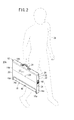
第1実施形態に係る放射線画像撮影装置10Aは、図1及び図2に示すように、外形が略矩形状の筐体で且つ放射線46(図5参照)を透過可能な材料からなるカセッテ本体部12と、カセッテ本体部12の一側面14aの両端から外方にそれぞれ突出形成された保持部材16a、16bによりカセッテ本体部12に保持される円柱状の放射線源本体部18とを有する。
As shown in FIGS. 1 and 2, the radiographic
この場合、カセッテ本体部12の一表面(照射面20)には、撮影領域及び撮影位置の基準となるガイド線22が形成されている。また、保持部材16a、16bが形成される側面14aとは反対側の側面14bには取手24が設けられている。さらに、カセッテ本体部12の残り2つの側面14c、14dのうち、一方の側面14cには、ACアダプタの入力端子26と、外部機器との間で情報の送受信が可能なインターフェース手段としてのUSB(Universal Serial Bus)端子28と、メモリカード30を装填するためのカードスロット32と、後述するロック解除ボタン(ロック解除手段)34とが設けられている。さらにまた、側面14cには、カセッテ本体部12から取り外し可能であり、且つ、表示部36と、医師又は放射線技師(以下、操作者38ともいう。)が操作する操作部40とが配置された携帯端末42が装着されている。一方、放射線源本体部18には、後述する放射線源44からの放射線46(図5参照)の出力を開始させるための曝射スイッチ48が設けられている。
In this case, a
なお、図1及び図2は、操作者38が放射線画像撮影装置10Aを搬送する際の該放射線画像撮影装置10Aの状態を示している。この場合、カセッテ本体部12と放射線源本体部18とは一体的に連結固定された状態にある。従って、操作者38は、取手24を把持した状態で放射線画像撮影装置10Aを所望の場所、例えば、災害現場や在宅看護の現場に搬送することにより、搬送先の現場において、当該放射線画像撮影装置10Aを用いた災害現場の被災者に対する放射線画像の撮影や、在宅看護が必要とされる在宅者に対する放射線画像の撮影を行うことが可能となる。以下の説明では、放射線画像の撮影対象となる前記被災者又は前記在宅者を被写体50(図6参照)ともいう。
1 and 2 show the state of the radiographic
ここで、カセッテ本体部12と放射線源本体部18との一体的な連結固定状態とは、後述する連結機構82(図3参照)によって、放射線画像撮影装置10Aが搬送可能な程度にカセッテ本体部12と放射線源本体部18とが一体的に連結されている状態をいう。
Here, the integrally connected and fixed state of the
次に、災害現場や在宅看護の現場等に可搬型の放射線画像撮影装置10Aを持ち込んだ場合の該放射線画像撮影装置10Aの状態について、図3〜図8を参照しながら説明する。
Next, the state of the radiographic
図3に示すように、カセッテ本体部12の側面14a〜14dを構成する側壁52a〜52dのうち、側壁52cに前述した入力端子26、USB端子28、カードスロット32及びロック解除ボタン34が配置されている。また、側壁52cにおけるカードスロット32とロック解除ボタン34との間の箇所は、内方に凹んだ凹部54とされ、この凹部54に携帯端末42が装着可能である。
As shown in FIG. 3, among the
ロック解除ボタン34は、操作者38(図2参照)による押圧操作に起因して側壁52aに沿って側壁52d側に変位可能である。この場合、ロック解除ボタン34の側壁52d側には、側壁52aに沿ったスライド部56が突出形成され、このスライド部56と側壁52aから内方に突出する突起58との間には、突起58から側壁52cの方向に向かって弾発するバネ部材60が介挿されている。また、スライド部56が接触する側壁52aの一部分には、カセッテ本体部12の内部と外部とを連通する孔62が形成され、該スライド部56の側部には、この孔62を貫通するフック部(フック部材、ロック手段)64が形成されている。
The
一方、図3及び図4に示すように、放射線源本体部18が保持部材16a、16bによりカセッテ本体部12に保持されているときに、該放射線源本体部18における孔62と対向する箇所には、該孔62と略同じ大きさの孔66が形成されている。従って、バネ部材60の弾発力によってフック部64が側壁52c側に変位することによりフック部64と孔66とが係合し、この結果、カセッテ本体部12に対して放射線源本体部18を一体的に連結固定することができる(図3参照)。
On the other hand, as shown in FIGS. 3 and 4, when the radiation source
また、放射線源本体部18における保持部材16a側の一方の端部には、導電性の接続端子(放射線源側接続端子)68aが装着され、保持部材16b側の他方の端部には、導電性の接続端子(放射線源側接続端子)68bが装着されている。この場合、接続端子68aは、保持部材16aに向って凸状とされ、一方で、接続端子68bは、保持部材16bに向って凹状とされている。
In addition, a conductive connection terminal (radiation source side connection terminal) 68a is attached to one end of the
これに対して、保持部材16aにおける放射線源本体部18側には、導電性の接続端子(カセッテ側接続端子)70aが装着され、保持部材16bにおける放射線源本体部18側には、導電性の接続端子(カセッテ側接続端子)70bが装着されている。この場合、接続端子70aは、接続端子68aに対応した凹状とされ、一方で、接続端子70bは、接続端子68bに対応した凸状とされている。
On the other hand, a conductive connection terminal (cassette side connection terminal) 70a is mounted on the
従って、図3に示すように、バネ部材60の弾発力によりフック部64と孔66とが係合してカセッテ本体部12と放射線源本体部18とが一体的に連結固定される状態では、凸状の接続端子68aと凹状の接続端子70aとが係合すると共に、凹状の接続端子68bと凸状の接続端子70bとが係合するので、カセッテ本体部12と放射線源本体部18との一体的な連結固定状態を確実に維持することができる。すなわち、これらの接続端子68a、68b、70a、70bは、フック部64及び孔66によるカセッテ本体部12と放射線源本体部18との一体的な連結固定状態の維持を補助するための部材としても機能する。
Therefore, as shown in FIG. 3, in a state where the
一方、図4に示すように、操作者38がロック解除ボタン34を押し、バネ部材60の弾発力に抗して該ロック解除ボタン34を側壁52dに移動させると、フック部64及びスライド部56が側壁52d側に変位して、フック部64と孔66との係合状態が解除される。従って、フック部64と孔66との係合状態が解除された状態(操作者38がロック解除ボタン34を押している状態)で、操作者38がカセッテ本体部12から放射線源本体部18を取り外す(分離する)ことにより、カセッテ本体部12と放射線源本体部18との一体的な連結固定状態が解除される。
On the other hand, as shown in FIG. 4, when the
また、カセッテ本体部12内には、メジャー(連結部材)72も配置されている。このメジャー72は、例えば、目盛74が振られた帯部材(帯)76を図示しないバネ部材の作用によってロール状に巻き取るメジャーであり、該メジャー72の側部には、メジャー72からの帯部材76の引き出し量を検出するロータリーエンコーダ(引き出し量検出部)78が取り付けられている。メジャー72から引き出された帯部材76の先端部は、側壁52aにおけるメジャー72と対向する箇所に形成された孔80を挿通して放射線源本体部18の接続端子68bの近傍に固定されている。
A measure (connecting member) 72 is also arranged in the
従って、図3に示すように、カセッテ本体部12に対して放射線源本体部18が一体的に連結固定される状態では、メジャー72内部のバネ部材の作用によって帯部材76の大部分が該メジャー72内でロール状に巻き取られる。一方、図4〜図8に示すように、カセッテ本体部12と放射線源本体部18との一体的な連結固定状態が解除されていれば、前記バネ部材の作用に抗してカセッテ本体部12から放射線源本体部18が離間することにより、メジャー72から孔80を介して帯部材76を引き出すことができる。
Therefore, as shown in FIG. 3, in the state where the radiation source
なお、上述したロック解除ボタン34、スライド部56、バネ部材60、フック部64、接続端子68a、68b、70a、70b及びメジャー72によって、放射線画像撮影装置10Aの搬送時にはカセッテ本体部12と放射線源本体部18とを一体的に連結固定し、一方で、撮影時にはカセッテ本体部12と放射線源本体部18とを離間させる連結機構82が構成される。
The cassette
また、上記の説明において、メジャー72は、目盛74が振られた帯部材76を巻取可能であるが、帯部材76に代替して、目盛74が振られた紐部材(紐)であっても帯部材76と同じ機能を奏することができることは勿論である。
Further, in the above description, the
さらに、カセッテ本体部12の内部には、図3及び図6に示すように、放射線源44から被写体50に放射線46を照射した際に、被写体50による放射線46の散乱線を除去するグリッド84、被写体50を透過した放射線46を検出する放射線検出器86、及び、放射線46のバック散乱線を吸収する鉛板88が、被写体50側の照射面20に対して順に配設される。なお、照射面20をグリッド84として構成してもよい。
Further, as shown in FIG. 3 and FIG. 6, a
この場合、放射線検出器86としては、例えば、被写体50を透過した放射線46をシンチレータにより可視光に一旦変換し、変換した前記可視光をアモルファスシリコン(a−Si)等の物質からなる固体検出素子(以下、画素ともいう。)により電気信号に変換する間接変換型の放射線検出器や、放射線46の線量をアモルファスセレン(a−Se)等の物質からなる固体検出素子により電気信号に直接変換する直接変換型の放射線検出器を採用することができる。
In this case, as the
さらに、カセッテ本体部12の内部には、図3に示すように、カセッテ本体部12を含む放射線画像撮影装置10Aの電源としてのバッテリ90と、バッテリ90から供給される電力により放射線検出器86(図6参照)を駆動制御するカセッテ制御部(制御手段)92と、放射線検出器86によって検出した放射線46の情報を含む信号を外部との間で送受信する送受信機(通信手段)94とが収容されている。なお、カセッテ制御部92及び送受信機94には、放射線46が照射されることによる損傷を回避するため、カセッテ制御部92及び送受信機94の照射面20側に鉛板等を配設しておくことが好ましい。
Further, inside the
ここで、バッテリ90は、カセッテ本体部12内のロータリーエンコーダ78、放射線検出器86、カセッテ制御部92及び送受信機94に電力を供給する。また、バッテリ90は、入力端子26を介して外部から電力供給(充電)を受けることも可能である。さらに、バッテリ90は、携帯端末42が凹部54に装着されているときに、該携帯端末42を充電することも可能である。さらにまた、バッテリ90は、接続端子70a、70bと電気的に接続されており、カセッテ本体部12に対して放射線源本体部18が一体的に連結固定された状態において、接続端子70a、70bから接続端子68a、68bを介して放射線源本体部18内のバッテリ(放射線源用バッテリ)96(図5参照)を充電することも可能である。この場合、バッテリ90、携帯端末42、及び/又は、バッテリ96の充電量や充電状態を表示部36に表示させることが望ましい。
Here, the
なお、送受信機94は、外部との信号の送受信が可能であるため、例えば、凹部54から取り外した携帯端末42の送受信機98(図11参照)との間での信号の送受信や、カセッテ本体部12から離間した放射線源本体部18の送受信機(通信手段)100との間での信号の送受信が可能である。勿論、カセッテ本体部12と放射線源本体部18とが一体的に連結固定され、及び/又は、凹部54に携帯端末42が装着されている場合であっても、各送受信機94、98、100間での信号の送受信は可能である。
Since the transmitter /
放射線源本体部18の内部には、図5に示すように、放射線源44と、バッテリ96と、送受信機100と、放射線源44を制御する線源制御部(制御手段)102と、レーザポインタ104と、カセッテ本体部12からの放射線源本体部18の離間に伴うバッテリ90からバッテリ96への充電の停止を検出する充電停止検出部105とが配置されている。
As shown in FIG. 5, the
放射線源44は、特許文献4と同様の電界放出型の放射線源である。
The
すなわち、この放射線源44は、回転機構106により回転する回転シャフト108に円盤状の回転陽極110が取り付けられ、該回転陽極110の表面には、Mo等の金属元素を主成分とする環状のターゲット層112が形成されている。一方、回転陽極110に対向して陰極114が配置され、該陰極114には、ターゲット層112と対向するように電界放出型電子源116が配設されている。
That is, in the
線源制御部102は、操作者38による曝射スイッチ48の操作に起因して、放射線46を出力させるように放射線源44を制御する。すなわち、放射線源44では、線源制御部102からの制御に従って、回転機構106が回転シャフト108を回転させることにより回転陽極110が回転し、電源部118がバッテリ96からの電力供給に基づいて電界放出型電子源116に電圧(負電圧)を印加し、且つ、電源部120がバッテリ96からの電力供給に基づいて回転陽極110と陰極114との間に電圧を印加すると(回転陽極110に正電圧を印加し、陰極114に負電圧を印加すると)、電界放出型電子源116から電子が放出され、放出された電子は、回転陽極110と陰極114との間に印加された電圧により加速されてターゲット層112に衝突する。ターゲット層112における電子の衝突面(焦点122)からは、該衝突した電子に応じた放射線46が外部に出力される。
The radiation
ここで、被写体50に放射線46を照射して、放射線画像の撮影を行う場合には、放射線源44の焦点122と該焦点122直下の放射線検出器86の位置124(図6参照)との間の距離(撮影間距離)を線源受像画間距離(SID)に予め設定し、且つ、照射面20における放射線46の照射範囲の中心位置と、ガイド線22の中心位置126(十字状に交差する2本のガイド線22の交点)とを一致させる作業を含めた撮影準備作業を行う必要がある。
Here, when a radiation image is taken by irradiating the subject 50 with the
この場合、操作者38は、図6及び図7に示すように、カセッテ本体部12から放射線源本体部18が離間した状態で、メジャー72からの帯部材76の引き出し量がSIDに応じた引き出し量l1となるまで該帯部材76を引き出す。また、レーザポインタ104は、線源制御部102からの制御に従って照射面20にレーザ光128を投光することにより、放射線46を照射面20に照射したときの該放射線46の照射範囲の中心位置を十字状のマーク130として照射面20に表示する。
In this case, as shown in FIGS. 6 and 7, the
なお、カセッテ本体部12からの放射線源本体部18の離間に伴ってバッテリ90からバッテリ96への充電が停止するので、充電停止検出部105は、バッテリ96に対する充電の停止を検出して線源制御部102に通知し、線源制御部102は、充電停止の通知を受け取ると、レーザ光128を投光するようにレーザポインタ104を制御する。
Since charging from the
また、位置124及び中心位置126と帯部材76が引き出される孔80が設けられた側面14aとの間の距離l2と、SIDに応じた引き出し量l1と、SIDとの間では、概ね、SID≒(l12+l22)1/2の関係が成り立つ。さらに、距離l2は一定である。
In addition, SID≈ is generally between the distance l2 between the
従って、引き出し量l1だけメジャー72から帯部材76を引き出した後に、照射面20に表示されたマーク130の位置と、中心位置126とが一致するように放射線源本体部18の位置を調整し、その後、図8に示すように、操作者38による曝射スイッチ48の投入に起因して、放射線源44から照射面20上に配置された被写体50に放射線46を照射することで、被写体50に対する放射線画像の撮影を適切に行うことが可能となる。なお、図8では、被写体50の手を撮影する場合について図示している。
Therefore, after the
放射線検出器86は、図9において模式的に示すように、多数の画素132が図示しない基板上に配列され、これらの画素132に対して制御信号を供給する多数のゲート線134と、多数の画素132から出力される電気信号を読み出す多数の信号線136とが配列されている。
As schematically shown in FIG. 9, the
次に、一例として、間接変換型の放射線検出器86を採用した場合のカセッテ本体部12の回路構成に関し、図10を参照しながら詳細に説明する。
Next, as an example, a circuit configuration of the
放射線検出器86は、可視光を電気信号に変換するa−Si等の物質からなる各画素132が形成された光電変換層138を、行列状のTFT140のアレイの上に配置した構造を有する。この場合、各画素132では、可視光を電気信号(アナログ信号)に変換することにより発生した電荷が蓄積され、各行毎にTFT140を順次オンにすることにより前記電荷を画像信号として読み出すことができる。
The
各画素132に接続されるTFT140には、行方向と平行に延びるゲート線134と、列方向と平行に延びる信号線136とが接続される。各ゲート線134は、ライン走査駆動部142に接続され、各信号線136は、マルチプレクサ144に接続される。ゲート線134には、行方向に配列されたTFT140をオンオフ制御する制御信号Von、Voffがライン走査駆動部142から供給される。この場合、ライン走査駆動部142は、ゲート線134を切り替える複数のスイッチSW1と、スイッチSW1の1つを選択する選択信号を出力するアドレスデコーダ146とを備える。アドレスデコーダ146には、カセッテ制御部92からアドレス信号が供給される。
To the
また、信号線136には、列方向に配列されたTFT140を介して各画素132に保持されている電荷が流出する。この電荷は、増幅器148によって増幅される。増幅器148には、サンプルホールド回路150を介してマルチプレクサ144が接続される。マルチプレクサ144は、信号線136を切り替える複数のスイッチSW2と、スイッチSW2の1つを選択する選択信号を出力するアドレスデコーダ152とを備える。アドレスデコーダ152には、カセッテ制御部92からアドレス信号が供給される。マルチプレクサ144には、A/D変換器154が接続され、A/D変換器154によってデジタル信号に変換された放射線画像がカセッテ制御部92に供給される。
In addition, the charge held in each
なお、スイッチング素子として機能するTFT140は、CMOS(Complementary Metal−Oxside Semiconductor)イメージセンサ等、他の撮像素子と組み合わせて実現してもよい。さらにまた、TFTで言うところのゲート信号に相当するシフトパルスにより電荷をシフトしながら転送するCCD(Charge−Coupled Device)イメージセンサに置き換えることも可能である。
Note that the
図11は、放射線画像撮影装置10Aのブロック図である。
FIG. 11 is a block diagram of the radiographic
なお、図11の説明では、図1〜図10において説明しなかった構成要素を中心に説明する。 In the description of FIG. 11, the description will focus on components that are not described in FIGS. 1 to 10.
カセッテ本体部12は、バッテリ90からの電力供給に基づいて凹部54に装着された携帯端末42に対する充電処理を行う携帯端末充電処理部156と、バッテリ90からの電力供給に基づいて接続端子68a、68b、70a、70bを介してバッテリ96に対する充電処理を行う放射線源充電処理部158と、操作者38がロック解除ボタン34を押すことによりフック部64と孔66との係合状態が解除されたことを検出するロック解除検出部160とをさらに有する。
The
携帯端末充電処理部156は、凹部54から携帯端末42が取り外されて、該携帯端末42に対する充電処理が行えない場合に、携帯端末42に対する充電処理の中断を示す信号をカセッテ制御部92に出力する。また、放射線源充電処理部158は、カセッテ本体部12から放射線源本体部18が離間して、接続端子68aと接続端子70aとの係合状態(電気的接続)、あるいは、接続端子68bと接続端子70bとの係合状態(電気的接続)が解除された結果、バッテリ96に対する充電処理が行えない場合に、バッテリ96に対する充電処理の中断を示す信号をカセッテ制御部92に出力する。さらに、ロック解除検出部160は、例えば、ロック解除ボタン34、スライド部56又はフック部64の位置を検出する位置検出センサであり、フック部64と孔66との係合状態が解除される位置にロック解除ボタン34、スライド部56又はフック部64が移動したときに、前記係合状態の解除を示す信号をカセッテ制御部92に出力する。
When the
また、カセッテ制御部92は、アドレス信号発生部162と、画像メモリ164と、カセッテIDメモリ166と、SID判定部(撮影間距離判定部)168と、充電制御部170とを備える。
The
アドレス信号発生部162は、ライン走査駆動部142のアドレスデコーダ146及びマルチプレクサ144のアドレスデコーダ152に対してアドレス信号を供給する。画像メモリ164は、放射線検出器86によって検出された放射線画像を記憶する。カセッテIDメモリ166は、放射線画像撮影装置10A(のカセッテ本体部12)を特定するためのカセッテID情報を記憶する。
The
SID判定部168は、ロータリーエンコーダ78から入力されるメジャー72からの帯部材76の引き出し量と、予め記憶された距離l2とに基づいて、現在の帯部材76の引き出し量で放射線源本体部18を照射面の上方に仮に配置したときの焦点122と位置124との間の撮影間距離を算出する。
The
次に、SID判定部168は、算出した撮影間距離がSIDに一致すれば、帯部材76の引き出し量をSIDに応じた引き出し量l1として、該引き出し量l1及び前記撮影間距離がSIDに一致したことを示す情報を送受信機94、98を介して表示部36に表示させる。一方、SID判定部168は、算出した撮影間距離がSIDに一致しなければ、現在の引き出し量と引き出し量l1との差及び撮影間距離がSIDに一致しないことを示す情報を送受信機94、98を介して表示部36に表示させる。
Next, if the calculated inter-shooting distance matches the SID, the
なお、SID判定部168、ロータリーエンコーダ78及びメジャー72によって撮影間距離設定手段169が構成される。
The
充電制御部170は、主として、バッテリ90から放射線検出器86への電力供給(図10に示すバイアス電圧Vbの印加)を制御する。具体的に、充電制御部170は、下記の制御処理を行う。
The
(1)放射線源充電処理部158及びロック解除検出部160からの信号の入力がない場合に、充電制御部170は、カセッテ本体部12と放射線源本体部18とが一体的に連結固定されており、従って、放射線源44からの放射線46の照射は行われない(非照射状態)と判断して、バッテリ90から放射線検出器86に対する電力供給を行わないように該バッテリ90を制御する。
(1) When there is no signal input from the radiation source charging
(2)放射線源充電処理部158又はロック解除検出部160からの信号の入力がある場合には、充電制御部170は、操作者38がカセッテ本体部12から放射線源本体部18を取り外している最中であるものと判断し、前記(1)と同様に、バッテリ90から放射線検出器86に対する電力供給を行わないように該バッテリ90を制御する。
(2) When there is a signal input from the radiation source
(3)放射線源充電処理部158及びロック解除検出部160からの信号の入力がある場合には、充電制御部170は、操作者38がカセッテ本体部12から放射線源本体部18を取り外して撮影準備作業を行っているものと判断し、放射線検出器86に電力供給を行って、該放射線検出器86を起動させるようにバッテリ90を制御する。
(3) When there is input of signals from the radiation source charging
すなわち、前記(1)又は(2)の場合には、放射線源44から放射線46が出力されることはないので、充電制御部170は、バッテリ90から放射線検出器86への電力供給を禁止して、カセッテ本体部12全体を放射線検出器86が起動しないスリープモードに維持する。一方、前記(3)の場合には、撮影準備作業の完了後に、操作者38が直ちに曝射スイッチ48を操作することで、放射線源44から放射線46が出力される可能性があるため、充電制御部170は、放射線源充電処理部158及びロック解除検出部160からの信号の入力があれば、直ちに、バッテリ90から放射線検出器86への電力供給を開始させて、放射線検出器86を起動させる。
That is, in the case of (1) or (2), since the
従って、スリープモード及び放射線検出器86の起動に関わりなく、バッテリ90は、ロータリーエンコーダ78、カセッテ制御部92、送受信機94、携帯端末充電処理部156、放射線源充電処理部158及びロック解除検出部160に対しては、常時、電力供給を行う。
Therefore, regardless of the sleep mode and the activation of the
なお、充電制御部170は、携帯端末充電処理部156からの信号の入力があれば、携帯端末42がカセッテ本体部12から取り外されているものと判断して、携帯端末充電処理部156への電力供給を禁止するように、バッテリ90を制御することも可能である。
In addition, if there is an input of a signal from the mobile terminal
また、前記(1)又は(2)の場合には、実際上、メジャー72からの帯部材76の引き出しは行われない。従って、充電制御部170は、前記(1)又は(2)の場合には、ロータリーエンコーダ78への電力供給を禁止するようにバッテリ90を制御し、一方で、前記(3)の場合には、ロータリーエンコーダ78への電力供給を開始するようにバッテリ90を制御することも可能である。
In the case of (1) or (2), the
カセッテ制御部92は、送受信機94を介して、カセッテIDメモリ166に記憶されたカセッテID情報と、画像メモリ164に記憶された放射線画像とを無線通信により携帯端末42に送信することも可能である。
The
第1実施形態に係る放射線画像撮影装置10Aは、基本的には以上のように構成されるものであり、次にその動作(放射線画像撮影方法)について、図12のフローチャートを参照しながら説明する。
The radiographic
ステップS1において、連結機構82によってカセッテ本体部12と放射線源本体部18とが一体的に連結固定された状態で、医師又は放射線技師の操作者38は、連結固定状態にある放射線画像撮影装置10Aの取手24を把持した状態で災害現場や在宅看護の現場に該放射線画像撮影装置10Aを搬送し、搬送先の現場において、携帯端末42の操作部40を操作することにより、撮影対象である被写体50に関わる被写体情報(例えば、SID)等の撮影条件を登録する。
In step S1, in the state where the cassette
この場合、操作者38は、携帯端末42を凹部54から取り外した状態で操作してもよいし、携帯端末42をカセッテ本体部12に装着した状態で操作してもよい。また、撮影部位や撮影方法が予め決まっている場合には、これらの撮影条件も予め登録しておく。なお、搬送先の現場に出向く前に、撮影対象の被写体50が予め分かっている場合には、操作者38の所属する医療機関等で携帯端末42を操作し、被写体情報を登録してもよい。
In this case, the
このようにして、操作者38が携帯端末42の操作部40を操作することにより、撮影対象である被写体50に関わる被写体情報等の撮影条件は、送受信機98から無線通信により送受信機94に送信され、カセッテ制御部92に登録される。
In this way, when the
なお、ステップS1において、カセッテ本体部12は、充電制御部170によって、バッテリ90から放射線検出器86への電力供給が禁止されたスリープモードに設定されている。従って、バッテリ90は、ロータリーエンコーダ78、カセッテ制御部92、送受信機94、携帯端末充電処理部156、放射線源充電処理部158及びロック解除検出部160に対して電力供給を行っている。
In step S <b> 1, the
次のステップS2において、操作者38がロック解除ボタン34を押すと、バネ部材60の弾発力に抗してフック部64が側壁52d側に変位するので、フック部64と孔66との係合状態が解除される。ロック解除検出部160は、前記係合状態の解除を検出し、検出結果を示す信号を充電制御部170に出力する。
In the
そして、前記係合状態の解除中(ロック解除ボタン34を押したままの状態)に、操作者38がカセッテ本体部12から放射線源本体部18を取り外すと、接続端子68aと接続端子70aとの係合状態と、接続端子68bと接続端子70bとの係合状態とが共に解除されて、カセッテ本体部12と放射線源本体部18との一体的な連結固定状態が解除される。これにより、放射線源充電処理部158は、放射線源本体部18のバッテリ96に対する充電処理の中断を示す信号を充電制御部170に出力する。
When the
ステップS3において、充電制御部170は、ロック解除検出部160及び放射線源充電処理部158からの各信号に基づいて、操作者38がカセッテ本体部12から放射線源本体部18を分離して撮影準備作業を開始したものと判断し、放射線検出器86に対する電力供給(バイアス電圧Vbの印加)を開始するようにバッテリ90を制御する。これにより、放射線検出器86は、バッテリ90からの電力供給に起因して速やかに起動し、カセッテ本体部12全体がスリープモードから起動状態へと移行する。
In step S <b> 3, the charging
次のステップS4において、操作者38は、撮影間距離の設定作業と、照射面20に表示されるマーク130とガイド線22の中心位置126とを一致させる設定作業とを行った後に、照射面20と放射線源本体部18との間に被写体50を配置して、該被写体50の位置決めを行う。
In the next step S <b> 4, the
この場合、操作者38は、先ず、放射線源本体部18を動かしてメジャー72からの帯部材76の引き出し量がSIDに応じた引き出し量l1となるまで該帯部材76を引き出す。
In this case, the
なお、引き出し量l1となるまで帯部材76を引き出す方法としては、次の2つの方法がある。
There are the following two methods for pulling out the
第1の方法は、引き出し量l1に到達したか否かをSID判定部168が自動的に判定し、該SIDに応じた引き出し量l1となるまで操作者38に帯部材76を引き出させる方法である。
The first method is a method in which the
第1の方法において、ロータリーエンコーダ78は、帯部材76の引き出し量を検出し、SID判定部168は、検出された前記引き出し量に基づいて、現在の帯部材76の引き出し量で放射線源本体部18を照射面20の上方に仮に配置したときの焦点122と位置124との間の撮影間距離を算出する。
In the first method, the
SID判定部168は、撮影間距離がSIDに一致していれば、帯部材76の引き出し量(引き出し量l1)及び撮影間距離がSIDに一致したことを示す情報を送受信機94、98を介して表示部36に表示させ、一方で、撮影間距離がSIDに一致しなければ、現在の引き出し量と引き出し量l1との差及び撮影間距離がSIDに一致しないことを示す情報を送受信機94、98を介して表示部36に表示させる。
If the distance between images matches the SID, the
そのため、第1の方法によれば、操作者38は、表示部36の表示内容に従ってメジャー72から帯部材76を引き出せばよいので、撮影間距離の設定作業を簡単に行うことができる。
Therefore, according to the first method, the
第2の方法は、引き出し量l1が予め分かっている場合に、操作者38が目盛74を見ながら、引き出し量l1となるまで帯部材76をメジャー72から引き出す方法である。
The second method is a method in which the
このようにしてSIDに応じた引き出し量l1となるまで帯部材76が引き出された後に、操作者38は、照射面20と対向するように放射線源本体部18を移動させる。
Thus, after the
この場合、充電停止検出部105は、カセッテ本体部12からの放射線源本体部18の離間に伴うバッテリ96の充電停止を検出し、検出結果を線源制御部102に通知する。従って、線源制御部102は、充電停止検出部105からの通知に基づいて、照射面20にレーザ光128を投光するようにレーザポインタ104を制御する。これにより、照射面20には、放射線46を照射面20に照射したときの該放射線46の照射範囲の中心位置が十字状のマーク130として表示される。これにより、操作者38は、マーク130の位置と、中心位置126とが一致するように放射線源本体部18の位置を調整する。
In this case, the charging
このようにして、マーク130の位置と中心位置126とが一致するように放射線源本体部18の位置を調整した後に、操作者38は、被写体50の撮影部位の中心が中心位置126(マーク130の位置)と一致するように、被写体50を照射面20上に配置(位置決め)する。
Thus, after adjusting the position of the
なお、放射線源本体部18は、上述の位置調整が行われた後は、例えば、図示しない保持部材により調整後の位置に固定される。
The
被写体50の位置決め後のステップS5において、操作者38は、曝射スイッチ48を投入して被写体50に対する撮影を開始させる。
In step S5 after the positioning of the subject 50, the
曝射スイッチ48の操作に起因して、線源制御部102は、無線通信により、カセッテ制御部92に対して撮影条件の送信を要求し、カセッテ制御部92は、受信した前記要求に基づいて、当該被写体50の撮影部位に係る撮影条件(制御信号)を、放射線源本体部18に送信する。線源制御部102は、前記撮影条件を受信すると、レーザポインタ104によるレーザ光128の投光を停止させると共に、当該撮影条件に従って、所定の線量からなる放射線46を被写体50に照射するように放射線源44を制御する。
Due to the operation of the
これにより、放射線源44内では、線源制御部102からの制御に従って、回転機構106が回転シャフト108及び回転陽極110を回転させ、一方で、電源部118がバッテリ96からの電力供給に基づいて電界放出型電子源116に負電圧を印加すると共に、電源部120がバッテリ96からの電力供給に基づいて回転陽極110と陰極114との間に電圧を印加するので、電界放出型電子源116から放出された電子は、回転陽極110と陰極114との間に印加された電圧により加速されてターゲット層112に衝突し、ターゲット層112の電子の衝突面(焦点122)からは、該衝突した電子に応じた放射線46が外部に出力される。
Thereby, in the
ステップS6において、撮影条件に基づく所定の照射時間だけ被写体50に放射線46が照射されると、該放射線46は、被写体50を透過してカセッテ本体部12内の放射線検出器86に至る。
In step S <b> 6, when the subject 50 is irradiated with the
ステップS7において、放射線検出器86が間接変換型の放射線検出器である場合に、該放射線検出器86を構成するシンチレータは、放射線46の強度に応じた強度の可視光を発光し、光電変換層138を構成する各画素132は、可視光を電気信号に変換し、電荷として蓄積する。次いで、各画素132に保持された被写体50の放射線画像である電荷情報は、カセッテ制御部92を構成するアドレス信号発生部162からライン走査駆動部142及びマルチプレクサ144に供給されるアドレス信号に従って読み出される。
In step S7, when the
すなわち、ライン走査駆動部142のアドレスデコーダ146は、アドレス信号発生部162から供給されるアドレス信号に従って選択信号を出力してスイッチSW1の1つを選択し、対応するゲート線134に接続されたTFT140のゲートに制御信号Vonを供給する。一方、マルチプレクサ144のアドレスデコーダ152は、アドレス信号発生部162から供給されるアドレス信号に従って選択信号を出力してスイッチSW2を順次切り替え、ライン走査駆動部142によって選択されたゲート線134に接続された各画素132に保持された電荷情報である放射線画像を信号線136を介して順次読み出す。
That is, the
選択されたゲート線134に接続された各画素132から読み出された放射線画像は、各増幅器148によって増幅された後、各サンプルホールド回路150によってサンプリングされ、マルチプレクサ144を介してA/D変換器154に供給され、デジタル信号に変換される。デジタル信号に変換された放射線画像は、カセッテ制御部92の画像メモリ164に一旦記憶される(ステップS8)。
The radiation image read out from each
同様にして、ライン走査駆動部142のアドレスデコーダ146は、アドレス信号発生部162から供給されるアドレス信号に従ってスイッチSW1を順次切り替え、各ゲート線134に接続されている各画素132に保持された電荷情報である放射線画像を信号線136を介して読み出し、マルチプレクサ144及びA/D変換器154を介してカセッテ制御部92の画像メモリ164に記憶させる(ステップS8)。
Similarly, the
画像メモリ164に記憶された放射線画像は、送受信機94を介して、無線通信により携帯端末42に送信され、携帯端末42は、図13に示すように、受信した放射線画像を表示部36に表示させる(ステップS9)。これにより、操作者38は、表示部36に表示された放射線画像を確認することにより、被写体50の撮影部位に対する撮影が適切に行われたか否かを把握することができる。
The radiographic image stored in the
例えば、撮影領域内に撮影部位の収まっていない放射線画像が表示された場合に、操作者38は、今回の撮影が適切に行われなかったものと判断して、被写体50に対する再撮影を実行する。
For example, when a radiographic image that does not fit in the imaging region is displayed in the imaging region, the
なお、表示部36に表示される放射線画像は、今回の撮影が適切であったか否かを判断できる程度の画像であればよいので、画像メモリ164に記憶されている放射線画像でもよいし、ローデータの画像であってもよいし、あるいは、比較的低い解像度に加工された画像であってもよい。
Note that the radiographic image displayed on the
次のステップS10において、撮影後の放射線源本体部18をカセッテ本体部12の側面14a側にまで移動させると、メジャー72内のバネ部材による帯部材76の巻き取りが開始される。そして、孔66と孔62とを対向させた状態で、接続端子68a、70aを係合させると共に、接続端子68b、70bを係合させると、孔66にフック部64が係合し、カセッテ本体部12に対して放射線源本体部18が一体的に連結固定される。
In the
これにより、ロック解除検出部160は、充電制御部170への信号の出力を停止する。また、放射線源充電処理部158は、充電制御部170への信号の出力を停止する一方で、接続端子68a、68b、70a、70bを介したバッテリ96への充電を再開する。
As a result, the lock
充電制御部170は、ロック解除検出部160及び放射線源充電処理部158からの信号の入力停止により、カセッテ本体部12と放射線源本体部18とが一体的な連結固定状態に至ったものと判断し、放射線検出器86に対する電力供給を停止するようにバッテリ90を制御する。この結果、カセッテ本体部12を含めた放射線画像撮影装置10Aは、スリープモードに移行する(ステップS11)。
The charging
そして、操作者38は、自己が所属する医療機関等に放射線画像撮影装置10Aを持ち帰り、画像メモリ164内に記憶された放射線画像を送受信機94を介した無線通信により、あるいは、USB端子28を介した有線通信により院内ネットワークの各種機器に送信するか、あるいは、メモリカード30に前記放射線画像を保存し、保存後のメモリカード30をカードスロット32から取り出して前記各種機器に提供する。これにより、前記医療機関において、前記放射線画像に対する詳細な読影診断を実施することが可能となる。
Then, the
以上説明したように、第1実施形態に係る放射線画像撮影装置10A及び放射線画像撮影方法によれば、放射線画像撮影装置10Aの移動時には、放射線源本体部18とカセッテ本体部12とを連結機構82により一体的に連結固定した状態で移動し、一方で、撮影時には、放射線源本体部18とカセッテ本体部12とを分離した後に、放射線源本体部18に収容された放射線源44から放射線46を出力して、被写体50に放射線46を照射するので、小型化及び軽量化が図られた可搬型の放射線画像撮影装置10Aであっても、撮影準備を簡単に且つ短時間で行うことが可能となる。
As described above, according to the radiographic
また、放射線源本体部18とカセッテ本体部12とが分離したときに、カセッテ制御部92の充電制御部170は、放射線検出器86に電力供給を行うようにバッテリ90を制御するので、撮影準備中に放射線検出器86を速やかに起動させることができる。
Further, when the radiation source
一方、放射線源本体部18とカセッテ本体部12とが一体的に連結固定されたときに、充電制御部170は、放射線検出器86への電力供給を停止するようにバッテリ90を制御するので、起動中の放射線検出器86を速やかに停止させることができる。
On the other hand, when the
このように、連結機構82による放射線源本体部18とカセッテ本体部12との連結固定状態、あるいは、分離状態に応じて、放射線検出器86の起動又は停止が行われるので、放射線画像撮影装置10Aの省電力化を図ることができる。
Thus, since the
また、メジャー72から帯部材76を引き出し量l1だけ引き出すことにより、撮影間距離をSIDに設定する作業を容易に行うことが可能となる。この場合、ロータリーエンコーダ78によって帯部材76の引き出し量を検出し、SID判定部168により撮影間距離とSIDとが一致するか否かを判定し、表示部36により判定結果を表示させることにより、帯部材76の引き出し量がSIDに応じた引き出し量l1であるか否かを操作者38に通知することができ、この結果、SIDの設定作業を容易に行うことが可能となる。
Further, by pulling out the
また、帯部材76には目盛74が設けられているので、操作者38は、この目盛74を見ながら引き出し量l1だけ引き出すことも可能となる。これにより、撮影時に、被写体50に対して適切な線量の放射線46を照射することが可能となる。また、目盛74が設けられていることにより、撮影準備中に被写体50の撮影部位の寸法を計測することも可能となる。さらに、引き出し量l1だけ帯部材76を引き出す場合のみならず、所定長さだけ帯部材76を引き出し、カセッテ制御部92では、前記所定長さに応じたSIDの値を撮影条件として再設定してもよい。
Further, since the
ところで、従来の放射線画像の撮影では、放射線46の照射条件として、放射線46の質に関しては放射線源44の管電圧が重要視され、放射線46の量に関してはmA・s値(電流と照射時間との積であり、放射線46の総曝射量)が重要視されていた。
By the way, in the conventional radiographic imaging, the tube voltage of the
しかしながら、線量管理上、放射線源44の焦点122と放射線検出器86の位置124との間の撮影間距離(SID)がどのような距離に設定されているのかという条件も、放射線46の照射条件として重要視されてきている。すなわち、撮影間距離の2乗に反比例して放射線46の線量が低下するため、放射線源44の管電圧及びmA・s値に応じた曝射量の放射線46を出力しても、SIDの値によって被写体50に実際に照射される放射線46の線量が異なってくるためである。
However, in terms of dose management, the conditions for the distance between images (SID) between the
そこで、第1実施形態においては、前述のように、帯部材76の引き出し量を引き出し量l1に設定するのに加え、該引き出し量l1やSID等の撮影条件を放射線画像と共に画像メモリ164を記憶し、あるいは、これらの撮影条件を放射線画像と共に表示部36に表示させるようにしてもよい。これにより、当該放射線画像がいかなる管電圧、mA・s値及びSIDにおいて撮影された画像であるのかが明らかになるので、災害現場や在宅介護の現場での撮影によって得られた放射線画像であっても、線量管理を簡便に行うことが可能となる。
Therefore, in the first embodiment, as described above, in addition to setting the pull-out amount of the
また、カセッテ本体部12に送受信機94が設けられると共に、放射線源本体部18に送受信機100が設けられているので、カセッテ制御部92と線源制御部102とは、送受信機94、100を介して信号の送受信を行うことが可能となる。従って、曝射スイッチ48の投入に起因した放射線源44からの放射線46の出力と、放射線検出器86における放射線46から前記放射線画像への変換との同期を容易に取ることができる。なお、上述の同期に合わせて、バッテリ96への電力供給を行ってもよい。
In addition, since the
さらに、フック部64と孔66とを係合させることにより、放射線源本体部18とカセッテ本体部12との一体的な連結固定状態を容易に実現することができる。
Further, by engaging the
さらにまた、保持部材16a、16bにより放射線源本体部18の両端部が保持されるので、放射線源本体部18とカセッテ本体部12との一体的な連結固定状態を維持することが可能となる。
Furthermore, since both ends of the radiation source
また、放射線源本体部18の両端部には、接続端子68a、68bがそれぞれ設けられ、保持部材16a、16bには、接続端子68a、68bに対向して接続端子70a、70bがそれぞれ設けられ、保持部材16a、16bにより放射線源本体部18の両端部が保持されたときに、接続端子68a、70aと接続端子68b、70bとがそれぞれ係合するので、放射線源本体部18とカセッテ本体部12との一体的な連結固定状態の維持を容易に図ることができる。
Further,
この場合、接続端子68a、68bと接続端子70a、70bとでは、一方が凸状であれば、他方が凹状となっているので、接続端子68a、70aと接続端子68b、70bとを確実に係合させることができる。また、一方を凸、他方を凹としているので、操作者38が誤って放射線源本体部18を左右反対にした状態で、該放射線源本体部18をカセッテ本体部12に連結固定させることを確実に防止することができる。
In this case, if one of the
しかも、接続端子70a、70bは、カセッテ本体部12内のバッテリ90に電気的に接続され、一方で、接続端子68a、68bは、放射線源本体部18内のバッテリ96に電気的に接続されている。従って、接続端子68a、70aと接続端子68b、70bとが係合していれば、バッテリ90から接続端子68a、68b、70a、70bを介してバッテリ96を確実に充電することができる。
Moreover, the
この場合、少なくとも被写体50の撮影枚数に応じた充電量だけバッテリ96を充電することにより、撮影時に、前記撮影枚数分の撮影を確実に行うことができる。
In this case, by charging the
なお、第1実施形態は、上述した説明に限定されることはなく、下記のように変更することも可能である。 In addition, 1st Embodiment is not limited to the description mentioned above, It is also possible to change as follows.
上述の説明では、放射線源本体部18とカセッテ本体部12とが分離したときに放射線検出器86が起動するようにしているが、分離したときに放射線源44も併せて起動できるようにしてもよい。この場合、放射線源本体部18とカセッテ本体部12とを連結固定したときに、放射線源44も併せて停止させるようにしてもよい。
In the above description, the
また、放射線源本体部18とカセッテ本体部12とが分離したときに放射線画像撮影装置10A全体が起動し、一方で、放射線源本体部18とカセッテ本体部12とが一体的に連結固定したときに放射線画像撮影装置10A全体が停止状態(スリープモード)になるようにしてもよい。
When the
また、上記の説明では、曝射スイッチ48の投入によって撮影が開始されるが、携帯端末42の操作部40の操作に起因して撮影が開始されてもよい。すなわち、操作部40のボタンの1つを曝射スイッチ専用のボタンにすればよい。
In the above description, shooting is started when the
さらに、カセッテ本体部12は、筐体の形状を有しているが、放射線検出器86等の箇所については、可撓性を有するシート状の形状としてもよい。シート状とすることでロール状に巻取可能となるので、カセッテ本体部12を含めた放射線画像撮影装置10A全体のさらなる小型化及び軽量化を実現することができる。
Furthermore, although the
また、撮影時の放射線源本体部18は、図示しない保持部材によって所定位置に固定されるが、少なくとも撮影中、操作者38が放射線源本体部18を手で持つようにしてもよい。
Further, the radiation source
さらに、上記の説明では、バッテリ90からバッテリ96を充電する場合について説明したが、バッテリ96を放射線画像撮影装置10A全体の電源とみなし、このバッテリ96からバッテリ90を充電してもよい。
Furthermore, in the above description, the case where the
さらにまた、上記の説明では、撮影時には、カセッテ制御部92から線源制御部102に撮影条件(制御信号)を送信することで、放射線源44からの放射線46の出力と、放射線検出器86における放射線46から放射線画像への変換との同期を取るようにしていたが、これに代えて、線源制御部102に撮影条件を予め登録する機能を具備させておき、曝射スイッチ48の投入に起因して、あるいは、カセッテ本体部12と放射線源本体部18との離間に起因して、前記撮影条件を線源制御部102からカセッテ制御部92に送信するように変更することも可能である。
Furthermore, in the above description, at the time of imaging, the imaging control (control signal) is transmitted from the
また、第1実施形態では、放射線源本体部18とカセッテ本体部12との間で、無線通信により信号の送受信が行われるので、信号を送受信するためのケーブルが不要となり、操作者38の作業に支障を来すおそれがない。従って、操作者38は、自己の作業を効率よく行うことが可能となる。
In the first embodiment, since signals are transmitted and received by radio communication between the radiation source
さらに、第1実施形態は、光読出方式の放射線検出器を利用して放射線画像を取得する場合にも適用することが可能である。この光読出方式の放射線検出器では、各固体検出素子に放射線が入射すると、その線量に応じた静電潜像が固体検出素子に蓄積記録される。静電潜像を読み取る際には、放射線検出器に読取光を照射し、発生した電流の値を放射線画像として取得する。なお、放射線検出器は、消去光を放射線検出器に照射することで、残存する静電潜像である放射線画像を消去して再使用することができる(特開2000−105297号公報参照)。 Furthermore, the first embodiment can also be applied to a case where a radiation image is acquired using an optical readout radiation detector. In this light readout type radiation detector, when radiation enters each solid detection element, an electrostatic latent image corresponding to the dose is accumulated and recorded in the solid detection element. When reading the electrostatic latent image, the radiation detector is irradiated with reading light, and the value of the generated current is acquired as a radiation image. Note that the radiation detector can erase and reuse the radiation image, which is the remaining electrostatic latent image, by irradiating the radiation detector with erasing light (see Japanese Patent Application Laid-Open No. 2000-105297).
さらにまた、放射線画像撮影装置10Aでは、血液やその他の雑菌が付着するおそれを防止するために、例えば、装置全体を防水性、密閉性を有する構造とし、必要に応じて殺菌洗浄することにより、1つの放射線画像撮影装置10Aを繰り返し続けて使用することができる。
Furthermore, in the
また、放射線画像撮影装置10Aと外部機器との間での無線通信は、通常の電波による通信に代えて、赤外線等を用いた光無線通信で行うようにしてもよい。
Further, the wireless communication between the
第1実施形態では、図14に示すように、メジャー72がない構成としてもよい。この場合であっても、メジャー72以外の構成要素による効果が容易に得られる。
In the first embodiment, as shown in FIG. 14, the
さらに、上記の説明では、連結機構82の主要な構成要素がカセッテ本体部12に配置されている場合について説明したが、放射線源本体部18に連結機構82を配置しても、上述した各効果が容易に得られる。
Further, in the above description, the case where the main components of the
図15は、ロック解除ボタン34及びフック部64等を放射線源本体部18に設けた変形例を示す。
FIG. 15 shows a modified example in which the
この場合、カセッテ本体部12の側面14aには、保持部材16a、16bが形成されておらず、一方で、放射線源本体部18における側面14a側は、側面14aに対応して平坦な形状とされている。そして、放射線源本体部18の両端部にロック解除ボタン34が設けられ、平坦部分における両端部近傍に孔62、フック部64が設けられると共に、前記平坦部分における一方の端部側に接続端子68a、68bが配置されている。
In this case, the holding
これに対して、カセッテ本体部12の側面14aには、孔62に対向して孔66が設けられると共に、接続端子68a、68bに対向して接続端子70a、70bが設けられている。
In contrast, the
図15の放射線画像撮影装置10Aでは、放射線源本体部18の平坦部分と、カセッテ本体部12の側面14aとを対向させた状態で、フック部64を孔66に係合させると共に、接続端子68a、68bと接続端子70a、70bとをそれぞれ係合させることにより、放射線源本体部18とカセッテ本体部12とが一体的に連結固定される。
In the radiographic
この変形例においても、上述した各効果を容易に得ることができる。 Also in this modified example, each effect mentioned above can be acquired easily.
また、図15の変形例では、ロック解除ボタン34が放射線源本体部18の両端部に設けられているので、操作者38は、ロック解除ボタン34を押しながらカセッテ本体部12から放射線源本体部18を取り外すだけで、放射線源本体部18とカセッテ本体部12との一体的な連結固定状態を容易に解除させることができる。
In the modification of FIG. 15, the
さらに、第1実施形態では、病院内の必要な箇所に、図16に示すように、放射線画像撮影装置10Aのバッテリ90の充電を行うクレードル180を配置すると好適である。この場合、クレードル180は、バッテリ90の充電だけでなく、クレードル180の無線通信機能又は有線通信機能を用いて、病院内の外部機器との間で必要な情報の送受信を行うようにしてもよい。送受信する情報には、クレードル180に装填された放射線画像撮影装置10Aに記録された放射線画像を含めることができる。
Furthermore, in the first embodiment, it is preferable that a
また、クレードル180に表示部182を配設し、この表示部182に対して、装填された当該放射線画像撮影装置10Aの充電状態や、放射線画像撮影装置10Aから取得した放射線画像を含む必要な情報を表示させるようにしてもよい。
In addition, a
さらに、複数のクレードル180をネットワークに接続し、各クレードル180に装填されている放射線画像撮影装置10Aの充電状態をネットワークを介して収集し、使用可能な充電状態にある放射線画像撮影装置10Aの所在を確認できるように構成することもできる。
Further, a plurality of
なお、上記の説明では、災害現場や在宅看護の現場における放射線画像の撮影について説明したが、第1実施形態は、このような医療関連の放射線画像の撮影に限定されるものではなく、例えば、各種の非破壊検査における放射線画像の撮影にも適用可能であることは勿論である。 In the above description, radiographic imaging at a disaster site or home nursing site has been described. However, the first embodiment is not limited to such medical radiographic imaging. For example, Needless to say, the present invention can also be applied to radiographic imaging in various nondestructive inspections.
次に、第2実施形態に係る放射線画像撮影装置10Bについて、図17〜図23を参照しながら説明する。
Next, a
なお、この放射線画像撮影装置10Bにおいて、第1実施形態に係る放射線画像撮影装置10A(図1〜図16参照)と同じ構成要素については、同じ参照符号を付けて、その詳細な説明を省略し、以下同様とする。
In this radiographic
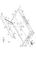
第2実施形態に係る放射線画像撮影装置10Bは、カセッテ本体部12と放射線源本体部18とがアーム(連結部材)190により連結されている点で、第1実施形態に係る放射線画像撮影装置10Aとは異なる。
The radiographic
すなわち、図17に示すように、カセッテ本体部12の各側面14c、14dにおける略中心部には、アーム190の基端部(軸)192がそれぞれ取り付けられ、該アーム190の先端部194は、放射線源本体部18の両端部にそれぞれ固定されている。従って、放射線源本体部18は、基端部192を軸としたアーム190の回動によって照射面20と対向することが可能である(図20及び図21参照)。この場合、アーム190の長さは、SIDに応じた長さに固定されているので、アーム190を回動させて放射線源本体部18を照射面20の上方に移動させることにより、撮影間距離をSIDに設定するための作業を容易に行うことができる。
That is, as shown in FIG. 17, a base end portion (shaft) 192 of the
図18A及び図18Bに示すように、フック部64は、連結部196を介してロック解除ボタン34と連結されている。この場合、連結部196の上端部にフック部64が形成され、一方で、連結部196の下端部にロック解除ボタン34が形成されている。また、カセッテ本体部12の照射面20側に形成された突起198と連結部196の上端部(フック部64)との間には、突起198からフック部64に向い弾発するバネ部材200が介挿され、一方で、カセッテ本体部12の底面202側に形成された突起204と連結部196の下端部(ロック解除ボタン34)との間には、突起204からロック解除ボタン34に向い弾発するバネ部材206が介挿されている。
As shown in FIGS. 18A and 18B, the
従って、図17及び図18Aに示すように、バネ部材200、206の弾発力によって、ロック解除ボタン34は、その一部が外部に露出すると共に、フック部64も孔62を貫通して外部に露出している。一方、バネ部材200、206の弾発力に抗して、操作者38がロック解除ボタン34を押すと、図18Bに示すように、外部に露出したフック部64の先端部が孔62内に引っ込む。
Accordingly, as shown in FIGS. 17 and 18A, a part of the
また、図19A〜図19Cに示すように、アーム190の円柱状の基端部192には、内方に向かう軸208が形成され、この軸に捩りバネ部材(アーム回動手段)210が装着されている。捩りバネ部材210の一端部212は、底面202に接触し、一方で、他端部214は、軸208に固定されている。この場合、捩りバネ部材210は、基端部192及び軸208を図19B及び図19C中の時計方向に回転させるように弾発する。
Also, as shown in FIGS. 19A to 19C, an
次に、図17及び図18Aに示すカセッテ本体部12と放射線源本体部18との一体的な連結固定状態から、図20及び図21に示す撮影時の状態にまで移行させるための放射線画像撮影装置10Bの動作について説明する。
Next, radiographic imaging for shifting from the integrally connected and fixed state of the
先ず、図17及び図18Aに示す連結固定状態において、操作者38がロック解除ボタン34を押すと、バネ部材200、206の弾発力に抗して連結部196が突起198、204側に変位し、この結果、アーム190の回動を規制するフック部64は、孔62内に一旦引っ込む(図18B参照)。
First, in the connected and fixed state shown in FIGS. 17 and 18A, when the
これにより、捩りバネ部材210の弾発力に起因して、基端部192及び軸208は、図19B及び図19Cの時計方向に回転するので、基端部192及び軸208の回転に伴ってアーム190も基端部192及び軸208を中心に回動する。この結果、カセッテ本体部12から放射線源本体部18が離間すると共に、放射線源本体部18は、照射面20の上方(中心位置126の上方)に移動するので、撮影間距離がSIDに自動的に設定されて、該撮影間距離の設定作業が完了するに至る。
Thereby, due to the elastic force of the
なお、アーム190の回動後、操作者38がロック解除ボタン34から手を離すと、連結部196は、バネ部材200、206の弾発力によって図18Aの位置に戻るので、フック部64は、再度外部に露出することになる。
When the
一方、撮影後、操作者38は、捩りバネ部材210の弾発力に抗してアーム190の先端部194を側面14a側にまで戻すと、アーム190が上方からフック部64を押圧するので、バネ部材200、206の弾発力に抗して連結部196が突起198、204側に変位し、この結果、該フック部64は孔62内に一旦引っ込む。その後、アーム190が図17及び図18Aの位置にまで下降すると、連結部196がバネ部材200、206の弾発力によって図18Aの位置に戻るので、フック部64は、外部に再度露出して、アーム190の回動を規制する。
On the other hand, after shooting, when the
以上説明したように、第2実施形態に係る放射線画像撮影装置10B及び放射線画像撮影方法によれば、フック部64とアーム190との係合を解除すると、基端部192及び軸208を中心にアーム190が回動するので、カセッテ本体部12と放射線源本体部18とが離間して、一体的な連結固定状態を自動的に解除することができる。
As described above, according to the radiographic
また、アーム190の長さがSIDに応じた長さに固定されているので、アーム190の回動によって放射線源本体部18を照射面20の上方に移動させるだけで、撮影間距離がSIDに自動的に設定される。従って、該撮影間距離の設定作業が容易になる。
Further, since the length of the
さらに、図17の位置から図20及び図21の位置にまでアーム190を回動させる捩りバネ部材210を基端部192の軸208に装着したことにより、撮影間距離の設定作業を容易に且つ正確に行うことが可能となる。
Further, since the
なお、図17〜図21では、アーム190の長さが固定である場合について説明したが、図22に示すように、テレスコピック構造のアーム190とすることにより、SIDを調整可能としてもよい。
In FIGS. 17 to 21, the case where the length of the
この場合、図23のブロック図に示すように、カセッテ本体部12内にアーム190の長さを検出するリニアエンコーダ(アーム長検出部)230を配置し、SID判定部168は、検出されたアーム190の長さに基づいてSIDを算出し、表示部36は、送受信機94、98を介して受信したSIDを表示する。これにより、操作者38は、表示部36の表示内容を見ることで、現在のアーム190の長さがどの程度のSIDの値に対応するものであるかを容易に把握することができる。
In this case, as shown in the block diagram of FIG. 23, a linear encoder (arm length detection unit) 230 for detecting the length of the
なお、第2実施形態では、アーム190の回動によって放射線源本体部18が中心位置126の上方に位置することになるので、レーザポインタ104(図11参照)が不要となる。また、図23の場合では、アーム190、リニアエンコーダ230及びSID判定部168によって撮影間距離設定手段169が構成される。
In the second embodiment, the radiation source
また、第2実施形態におけるバッテリ96に対する充電については、例えば、第1実施形態の場合と同様に、アーム190が図17の位置に固定されているときに、接続端子68a、68b、70a、70bを介して行えばよい。この場合、接続端子68a、68bは、例えば、アーム190又は放射線源本体部18に設けられ、一方で、接続端子70a、70bは、アーム190に対向する側面14c、14dの所定箇所、あるいは、放射線源本体部18に対向する側面14aの所定箇所に設けられる。従って、第2実施形態においても、第1実施形態の場合と同様に、カセッテ本体部12と放射線源本体部18との離間に起因して放射線検出器86等を起動することが可能である。
For charging the
次に、第3実施形態に係る放射線画像撮影装置10Cについて、図24〜図26を参照しながら説明する。 Next, a radiographic imaging apparatus 10C according to the third embodiment will be described with reference to FIGS.
第3実施形態に係る放射線画像撮影装置10Cは、放射線46又は該放射線46の散乱線が不用意に周囲に放射されることを防止するために、これらの放射線46又は散乱線を吸収する鉛からなるスクリーン220をロール状に巻き取って収容するロールスクリーン構造の収容ボックス(スクリーン収容部)222がカセッテ本体部12の側壁52a側に収容され、該スクリーン220の先端部が放射線源本体部18に固定されている点で、第2実施形態に係る放射線画像撮影装置10B(図17〜図23)とは異なる。
In order to prevent the
第3実施形態に係る放射線画像撮影装置10Cでは、スクリーン220を設けたことにより、撮影時に、被写体50以外の例えば操作者38が不要に被曝することを防止することができる。また、アーム190の回動に起因した放射線源本体部18の移動に伴って収容ボックス222からスクリーン220が自動的に引き出されるので、操作者38の撮影準備がより一層容易なものとなる。さらに、スクリーン220には目盛224が設けられているので、例えば、この目盛224を利用して被写体50の撮影部位の寸法を計測することも可能となる。
In the radiographic image capturing apparatus 10C according to the third embodiment, by providing the
また、収容ボックス222にロータリーエンコーダ78を取り付け、該収容ボックス222からのスクリーン220の引き出し量を検出してもよい。この場合、SID判定部168は、検出された引き出し量に基づいて撮影間距離を算出し、算出した撮影間距離とSIDとが一致するか否かを判定する。従って、スクリーン220を採用した場合であっても、撮影間距離をSIDに容易に設定することが可能である。
Alternatively, the
なお、本発明は、上述の実施の形態に限らず、本発明の要旨を逸脱することなく、種々の構成を採り得ることは勿論である。 Note that the present invention is not limited to the above-described embodiment, and it is needless to say that various configurations can be adopted without departing from the gist of the present invention.
10A〜10C…放射線画像撮影装置
12…カセッテ本体部
16a、16b…保持部材
18…放射線源本体部
34…ロック解除ボタン
36…表示部
44…放射線源
46…放射線
50…被写体
64…フック部
66…孔
68a、68b、70a、70b…接続端子
72…メジャー
76…帯部材
78…ロータリーエンコーダ
82…連結機構
86…放射線検出器
90、96…バッテリ
92…カセッテ制御部
94、98、100…送受信機
102…線源制御部
104…レーザポインタ
105…充電停止検出部
128…レーザ光
130…マーク
190…アーム
192…基端部
208…軸
210…捩りバネ部材
220…スクリーン
222…収容ボックス
10A to 10C ... Radiation
Claims (25)
前記放射線源が被写体に前記放射線を照射した際に、前記被写体を透過した放射線を検出して放射線画像に変換する放射線検出器を収容するカセッテ本体部と、
移動時には前記放射線源本体部と前記カセッテ本体部とを一体的に連結固定し、一方で、前記放射線の出力時には前記放射線源本体部と前記カセッテ本体部とを分離可能な連結機構と、
を有することを特徴とする放射線画像撮影装置。 A radiation source body that houses a radiation source that outputs radiation; and
A cassette body that houses a radiation detector that detects radiation transmitted through the subject and converts it into a radiation image when the radiation source irradiates the subject with the radiation;
A coupling mechanism capable of integrally connecting and fixing the radiation source body and the cassette body when moving, and capable of separating the radiation source body and the cassette body when outputting the radiation,
A radiographic imaging apparatus comprising:
前記連結機構が前記放射線源本体部と前記カセッテ本体部とを分離したときに、前記放射線源及び前記放射線検出器のうち、少なくとも一方を起動させる制御手段をさらに有することを特徴とする放射線画像撮影装置。 The apparatus of claim 1.
Radiographic imaging, further comprising control means for activating at least one of the radiation source and the radiation detector when the coupling mechanism separates the radiation source main body and the cassette main body. apparatus.
前記制御手段は、前記連結機構により前記放射線源本体部と前記カセッテ本体部とが一体的に連結固定されたときに、起動中の前記放射線源及び前記放射線検出器を停止させることを特徴とする放射線画像撮影装置。 The apparatus of claim 2.
The control means stops the radiation source and the radiation detector that are activated when the radiation source main body and the cassette main body are integrally connected and fixed by the connection mechanism. Radiation imaging device.
前記放射線源と前記放射線検出器との間の撮影間距離を線源受像画間距離に設定するための撮影間距離設定手段をさらに有することを特徴とする放射線画像撮影装置。 The device according to any one of claims 1 to 3,
A radiographic imaging apparatus, further comprising an inter-imaging distance setting means for setting an inter-imaging distance between the radiation source and the radiation detector as a source-receiver image distance.
前記連結機構は、前記放射線源本体部と前記カセッテ本体部とを連結する連結部材を備え、
前記連結部材は、前記放射線源本体部と前記カセッテ本体部とを離間させることにより前記撮影間距離設定手段の一部として機能することを特徴とする放射線画像撮影装置。 The apparatus of claim 4.
The coupling mechanism includes a coupling member that couples the radiation source main body and the cassette main body,
The connection member functions as a part of the inter-imaging distance setting unit by separating the radiation source main body and the cassette main body from each other.
前記連結部材は、前記放射線源本体部と前記カセッテ本体部とを連結するアーム、前記放射線源本体部及び前記カセッテ本体部のうち一方の本体部に設けられ且つ先端部が他方の本体部に固定された紐、帯又はスクリーンであることを特徴とする放射線画像撮影装置。 The apparatus of claim 5.
The connecting member is provided on one of the radiation source main body and the cassette main body, one of the radiation source main body and the cassette main body, and the tip is fixed to the other main body. A radiographic image capturing apparatus, wherein the radiographic image capturing apparatus is a string, a band, or a screen.
前記連結部材が前記アームである場合に、前記アームは、該アームの全長が前記線源受像画間距離に応じた一定の長さに設定されたアームであるか、あるいは、該アームが伸縮することにより前記撮影間距離を前記線源受像画間距離に調整することが可能なテレスコピック構造のアームであることを特徴とする放射線画像撮影装置。 The apparatus of claim 6.
When the connecting member is the arm, the arm is an arm whose entire length is set to a certain length corresponding to the distance between the source image and the arm extends or contracts. Thus, the radiographic imaging device is a telescopic arm capable of adjusting the inter-imaging distance to the radiation source-received image distance.
前記撮影間距離設定手段は、前記アームが前記テレスコピック構造のアームである場合に、伸縮した前記アームの長さを検出するアーム長検出部と、前記アーム長検出部が検出した前記アームの長さに基づいて前記撮影間距離を算出し、前記撮影間距離が前記線源受像画間距離に一致するか否かを判定する撮影間距離判定部とを備えることを特徴とする放射線画像撮影装置。 The apparatus of claim 7.
The inter-photographing distance setting means includes an arm length detection unit that detects the length of the arm that is expanded and contracted when the arm is an arm of the telescopic structure, and the length of the arm that is detected by the arm length detection unit. A radiographic imaging apparatus comprising: an inter-imaging distance determination unit that calculates the inter-imaging distance based on the image and determines whether or not the inter-imaging distance matches the source-receiver image inter-image distance.
前記連結部材が前記スクリーンである場合に、前記放射線源本体部及び前記カセッテ本体部のうち一方の本体部には、前記スクリーンをロール状に収容可能なスクリーン収容部が設けられ、
前記スクリーンの先端部は、他方の本体部に固定されていることを特徴とする放射線画像撮影装置。 The apparatus of claim 6.
When the connecting member is the screen, one of the radiation source main body and the cassette main body is provided with a screen storage capable of storing the screen in a roll shape,
A radiographic imaging apparatus, wherein a tip of the screen is fixed to the other main body.
前記撮影間距離設定手段は、前記一方の本体部からの前記紐若しくは前記帯の引き出し量、又は、前記スクリーン収容部からの前記スクリーンの引き出し量を検出する引き出し量検出部と、前記引き出し量検出部が検出した前記引き出し量に基づいて前記線源受像画間距離を算出する撮影間距離判定部とを備えることを特徴とする放射線画像撮影装置。 The device according to claim 6 or 9,
The inter-photographing distance setting means includes a pull-out amount detection unit that detects a pull-out amount of the string or the band from the one main body unit, or a pull-out amount of the screen from the screen storage unit, and the pull-out amount detection A radiographic image capturing apparatus comprising: an inter-imaging distance determination unit that calculates the distance between the source-source received images based on the drawing amount detected by the unit.
前記放射線源本体部と前記カセッテ本体部とが分離しているときに、前記放射線源からの前記放射線の出力と、前記放射線検出器における前記放射線から前記放射線画像への変換との同期を取るための制御信号を前記放射線源本体部と前記カセッテ本体部との間で送受信するための通信手段が前記放射線源本体部及び前記カセッテ本体部にそれぞれ収容されていることを特徴とする放射線画像撮影装置。 The device according to any one of claims 1 to 10,
To synchronize the output of the radiation from the radiation source and the conversion from the radiation to the radiation image in the radiation detector when the radiation source body and the cassette body are separated. A radiographic imaging apparatus, wherein communication means for transmitting / receiving the control signal between the radiation source main body and the cassette main body is accommodated in the radiation source main body and the cassette main body, respectively. .
前記連結機構は、前記放射線源本体部及び前記カセッテ本体部を一体的に連結固定させるロック手段と、前記ロック手段による前記放射線源本体部及び前記カセッテ本体部の一体的な連結固定状態を解除するロック解除手段とを備えることを特徴とする放射線画像撮影装置。 The apparatus according to any one of claims 1 to 11,
The coupling mechanism releases a unitary coupling and fixing state of the radiation source main body and the cassette main body by the locking means for integrally coupling and fixing the radiation source main body and the cassette main body, and the locking means. A radiographic imaging apparatus comprising: a lock release unit.
前記連結機構は、前記カセッテ本体部に設けられ、
前記ロック手段は、前記放射線源本体部の前記カセッテ本体部側に形成された孔に係合可能なフック部材であり、
前記ロック解除手段は、前記フック部材と前記孔との係合状態を解除して、前記カセッテ本体部から前記放射線源本体部を分離させるためのロック解除ボタンであることを特徴とする放射線画像撮影装置。 The apparatus of claim 12.
The coupling mechanism is provided in the cassette main body,
The locking means is a hook member that can be engaged with a hole formed on the cassette body part side of the radiation source body part,
The unlocking means is a lock release button for releasing the engaged state between the hook member and the hole and separating the radiation source main body from the cassette main body. apparatus.
前記カセッテ本体部には、前記放射線源本体部の両端部を保持することにより、前記フック部材及び前記孔の係合に起因した前記カセッテ本体部に対する前記放射線源本体部の一体的な連結固定状態を補助する保持部材が前記両端部に対向してそれぞれ設けられていることを特徴とする放射線画像撮影装置。 The apparatus of claim 13.
By holding both ends of the radiation source body in the cassette body, the radiation source body is integrally connected and fixed to the cassette body due to the engagement of the hook member and the hole. A radiographic imaging apparatus characterized in that holding members for assisting are provided to face both ends.
前記放射線源本体部には、前記放射線源を駆動するための放射線源用バッテリがさらに収容され、
前記放射線源本体部の両端部には、前記放射線源用バッテリに接続される放射線源側接続端子が前記各保持部材に対向してそれぞれ設けられ、
前記各保持部材には、前記放射線源本体部の両端部が保持されたときに、前記各放射線源側接続端子に接続されるカセッテ側接続端子がそれぞれ設けられていることを特徴とする放射線画像撮影装置。 The apparatus of claim 14.
The radiation source main body further contains a radiation source battery for driving the radiation source,
At both ends of the radiation source main body, radiation source side connection terminals connected to the radiation source battery are provided to face the holding members, respectively.
Each of the holding members is provided with a cassette side connection terminal that is connected to each of the radiation source side connection terminals when both ends of the radiation source main body are held. Shooting device.
前記連結機構は、前記放射線源本体部に設けられ、
前記ロック手段は、前記カセッテ本体部の前記放射線源本体部側に形成された孔に係合可能なフック部材であり、
前記ロック解除手段は、前記フック部材と前記孔との係合状態を解除して、前記放射線源本体部から前記カセッテ本体部を分離させるためのロック解除ボタンであることを特徴とする放射線画像撮影装置。 The apparatus of claim 12.
The coupling mechanism is provided in the radiation source main body,
The locking means is a hook member that can be engaged with a hole formed on the radiation source main body side of the cassette main body,
The unlocking means is a lock release button for releasing the engaged state between the hook member and the hole and separating the cassette main body from the radiation source main body. apparatus.
前記放射線源本体部には、前記放射線源を駆動するための放射線源用バッテリがさらに収容され、
前記放射線源本体部における前記カセッテ本体部側には、前記放射線源用バッテリに接続される2つの放射線源側接続端子が設けられ、
前記カセッテ本体部における前記放射線源本体部側には、前記各放射線源側接続端子と対向するように、カセッテ側接続端子がそれぞれ設けられていることを特徴とする放射線画像撮影装置。 The apparatus of claim 16.
The radiation source main body further contains a radiation source battery for driving the radiation source,
On the cassette body portion side of the radiation source body portion, two radiation source side connection terminals connected to the radiation source battery are provided,
A radiographic imaging apparatus, wherein a cassette side connection terminal is provided on the side of the radiation source body in the cassette body so as to face each of the radiation source side connection terminals.
前記各放射線源側接続端子のうち、一方の端子は凸状に形成されると共に、他方の端子は凹状に形成され、
前記各カセッテ側接続端子のうち、前記凸状の放射線源側接続端子に対向する一方の端子は凹状に形成されると共に、前記凹状の放射線源側接続端子に対向する他方の端子は凸状に形成されることを特徴とする放射線画像撮影装置。 18. Apparatus according to claim 15 or 17,
Among the radiation source side connection terminals, one terminal is formed in a convex shape, and the other terminal is formed in a concave shape,
Of each of the cassette side connection terminals, one terminal facing the convex radiation source side connection terminal is formed in a concave shape, and the other terminal facing the concave radiation source side connection terminal is in a convex shape. A radiographic image capturing device formed.
前記放射線源用バッテリは、前記各放射線源側接続端子が前記各カセッテ側接続端子にそれぞれ接続されている状態で、前記各放射線源側接続端子及び前記各カセッテ側接続端子を介して、少なくとも前記被写体の撮影枚数に応じた充電量だけ充電されることを特徴とする放射線画像撮影装置。 The apparatus according to any one of claims 15, 17 or 18,
The radiation source battery has at least the radiation source side connection terminals and the cassette side connection terminals via the radiation source side connection terminals and the cassette side connection terminals in a state where the radiation source side connection terminals are respectively connected to the cassette side connection terminals. A radiographic image capturing apparatus that is charged by a charge amount corresponding to the number of captured images of a subject.
前記連結機構は、前記放射線源本体部と前記カセッテ本体部とを連結するアームをさらに備え、
前記ロック手段は、前記放射線源本体部又は前記カセッテ本体部に接続された前記アームの基端部を中心とする該アームの回動を規制することにより、前記放射線源本体部及び前記カセッテ本体部を一体的に連結固定させ、
前記ロック解除手段は、前記ロック手段による前記アームの回動の規制状態を解除することによって、前記放射線源本体部及び前記カセッテ本体部の一体的な連結固定状態を解除することを特徴とする放射線画像撮影装置。 The apparatus of claim 12.
The connection mechanism further includes an arm that connects the radiation source main body and the cassette main body,
The locking means regulates the rotation of the arm around the base end of the arm connected to the radiation source main body or the cassette main body, whereby the radiation source main body and the cassette main body Are connected and fixed together,
The radiation releasing means releases the integrally connected and fixed state of the radiation source main body part and the cassette main body part by releasing the restricted state of the rotation of the arm by the locking means. Image shooting device.
前記連結機構は、前記ロック解除手段によって前記アームの回動の規制状態が解除されているときに、前記アームの基端部を中心として前記アームを回動させるアーム回動手段をさらに備えることを特徴とする放射線画像撮影装置。 The apparatus of claim 20.
The connection mechanism further includes arm rotation means for rotating the arm about the base end portion of the arm when the restricted state of rotation of the arm is released by the unlocking means. A radiographic imaging device as a feature.
前記ロック手段、前記ロック解除手段及び前記アーム回動手段は、前記カセッテ本体部に設けられ、
前記アームの基端部は、前記カセッテ本体部に接続されると共に、前記アームの先端部は、前記放射線源本体部に接続され、
前記ロック手段は、前記アームに係合することにより前記アーム回動手段による前記アームの回動を規制するフック部材であり、
前記ロック解除手段は、前記アームと前記フック部材との係合状態を解除することにより、前記アームを回動可能な状態とするためのロック解除ボタンであり、
前記アーム回動手段は、前記ロック解除ボタンにより前記アームが回動可能な状態となったときに、前記アームの基端部を中心として該アーム及び前記放射線源本体部を一体的に回動させる捩りバネ部材であることを特徴とする放射線画像撮影装置。 The apparatus of claim 21.
The locking means, the unlocking means, and the arm rotating means are provided in the cassette body,
The base end of the arm is connected to the cassette body, and the tip of the arm is connected to the radiation source body.
The locking means is a hook member that regulates rotation of the arm by the arm rotation means by engaging with the arm;
The unlocking means is a lock release button for releasing the engagement state between the arm and the hook member to make the arm rotatable.
The arm rotation means integrally rotates the arm and the radiation source main body around the base end portion of the arm when the arm can be rotated by the lock release button. A radiographic imaging device, characterized by being a torsion spring member.
移動後に前記放射線源本体部と前記カセッテ本体部とを分離し、
前記放射線源本体部に収容された放射線源から放射線を出力することにより、該放射線を被写体に照射し、
前記カセッテ本体部に収容された放射線検出器によって前記被写体を透過した放射線を検出して放射線画像に変換する
ことを特徴とする放射線画像撮影方法。 Move the radiation source body part and the cassette body part integrally connected and fixed by the connection mechanism,
Separating the radiation source main body and the cassette main body after movement,
By irradiating the subject with the radiation by outputting radiation from the radiation source housed in the radiation source main body,
A radiographic imaging method comprising: detecting radiation transmitted through the subject by a radiation detector housed in the cassette body and converting the radiation into a radiographic image.
前記放射線源本体部と前記カセッテ本体部との分離後に、撮影間距離設定手段により前記放射線源と前記放射線検出器との間の線源受像画間距離を設定し、
前記線源受像画間距離の設定後に前記放射線源から前記放射線を出力することを特徴とする放射線画像撮影方法。 24. The method of claim 23.
After separation of the radiation source main body and the cassette main body, the distance between the radiation source and the radiation detector between the radiation source and the radiation detector is set by an imaging distance setting means,
A radiation image capturing method, comprising: outputting the radiation from the radiation source after setting the distance between the source image and the image.
前記放射線検出器による前記放射線から前記放射線画像への変換後、前記連結機構により前記放射線源本体部と前記カセッテ本体部とを一体的に連結固定することで、起動中の前記放射線源及び前記放射線検出器を停止させることを特徴とする放射線画像撮影方法。 25. A method according to claim 23 or 24, wherein:
After the radiation detector converts the radiation into the radiation image, the radiation source main body and the cassette main body are integrally coupled and fixed by the coupling mechanism, so that the radiation source and the radiation being activated A radiographic imaging method comprising stopping a detector.
Priority Applications (2)
| Application Number | Priority Date | Filing Date | Title |
|---|---|---|---|
| JP2009178205A JP5241644B2 (en) | 2009-07-30 | 2009-07-30 | Radiation image capturing apparatus and radiation image capturing method |
| US12/805,255 US8345820B2 (en) | 2009-07-30 | 2010-07-21 | Radiographic image capturing apparatus and radiographic image capturing method |
Applications Claiming Priority (1)
| Application Number | Priority Date | Filing Date | Title |
|---|---|---|---|
| JP2009178205A JP5241644B2 (en) | 2009-07-30 | 2009-07-30 | Radiation image capturing apparatus and radiation image capturing method |
Publications (3)
| Publication Number | Publication Date |
|---|---|
| JP2011030665A JP2011030665A (en) | 2011-02-17 |
| JP2011030665A5 JP2011030665A5 (en) | 2012-02-02 |
| JP5241644B2 true JP5241644B2 (en) | 2013-07-17 |
Family
ID=43526110
Family Applications (1)
| Application Number | Title | Priority Date | Filing Date |
|---|---|---|---|
| JP2009178205A Active JP5241644B2 (en) | 2009-07-30 | 2009-07-30 | Radiation image capturing apparatus and radiation image capturing method |
Country Status (2)
| Country | Link |
|---|---|
| US (1) | US8345820B2 (en) |
| JP (1) | JP5241644B2 (en) |
Families Citing this family (14)
| Publication number | Priority date | Publication date | Assignee | Title |
|---|---|---|---|---|
| US9168016B2 (en) * | 2010-01-29 | 2015-10-27 | Fujifilm Corporation | Radiographic image capturing apparatus, radiographic image capturing system, and method of supplying electric power to radiographic image capturing apparatus |
| JP2012066062A (en) * | 2010-08-24 | 2012-04-05 | Fujifilm Corp | Radiographic image capturing system and radiographic image capturing method |
| US8576986B2 (en) | 2011-01-21 | 2013-11-05 | General Electric Company | X-ray system and method for sampling image data |
| US9629591B2 (en) * | 2011-01-21 | 2017-04-25 | General Electric Company | X-ray system and method with digital image acquisition |
| US8768035B2 (en) | 2011-04-27 | 2014-07-01 | General Electric Company | X-ray system and method for processing image data |
| JP2013070866A (en) * | 2011-09-28 | 2013-04-22 | Fujifilm Corp | Device, method, and program for assisting in initial setting of photographing condition, and radiation photographing apparatus and system |
| KR101854281B1 (en) | 2011-11-15 | 2018-05-04 | 삼성디스플레이 주식회사 | X-ray device |
| JP5917162B2 (en) * | 2012-01-19 | 2016-05-11 | キヤノン株式会社 | X-ray equipment |
| JP6021403B2 (en) * | 2012-04-19 | 2016-11-09 | キヤノン株式会社 | Radiation imaging device |
| JP6057736B2 (en) * | 2013-01-21 | 2017-01-11 | キヤノン株式会社 | X-ray equipment |
| JP6127850B2 (en) * | 2013-09-13 | 2017-05-17 | コニカミノルタ株式会社 | Portable radiography system |
| JP6050206B2 (en) * | 2013-09-17 | 2016-12-21 | 富士フイルム株式会社 | Radiation imaging system and communication environment control apparatus |
| DE102014201145A1 (en) * | 2014-01-22 | 2015-07-23 | Siemens Aktiengesellschaft | X-ray system for X-ray examination and its use |
| CN208598297U (en) * | 2017-01-26 | 2019-03-15 | 深圳洛克时代科技有限公司 | Intelligent cleaning equipment |
Family Cites Families (11)
| Publication number | Priority date | Publication date | Assignee | Title |
|---|---|---|---|---|
| JP2582593B2 (en) * | 1987-10-09 | 1997-02-19 | 富士写真フイルム 株式会社 | Radiation image information imaging device |
| JPH10225450A (en) | 1997-02-14 | 1998-08-25 | Toshiba Corp | X-ray diagnostic device |
| JP3284306B2 (en) * | 1997-08-08 | 2002-05-20 | 株式会社中日電子 | Medical X-ray equipment |
| JP3445164B2 (en) | 1997-08-19 | 2003-09-08 | 富士写真フイルム株式会社 | Electrostatic recording medium, electrostatic latent image recording device, and electrostatic latent image reading device |
| JP3465659B2 (en) * | 2000-03-10 | 2003-11-10 | 松下電器産業株式会社 | X-ray equipment |
| US7016467B2 (en) * | 2004-08-13 | 2006-03-21 | Jack Jerome Brooks | Mobile digital radiography x-ray apparatus and system |
| JP4653461B2 (en) * | 2004-11-17 | 2011-03-16 | 株式会社東芝 | Digital X-ray tomography apparatus |
| JP4515921B2 (en) * | 2005-01-07 | 2010-08-04 | 株式会社日立メディコ | Mobile X-ray device |
| JP2007103016A (en) | 2005-09-30 | 2007-04-19 | Konica Minolta Medical & Graphic Inc | X-ray image photographic system |
| JP4891096B2 (en) * | 2006-01-30 | 2012-03-07 | キヤノン株式会社 | Radiation imaging device |
| JP5296431B2 (en) * | 2007-07-30 | 2013-09-25 | 富士フイルム株式会社 | Radiation imaging system |
-
2009
- 2009-07-30 JP JP2009178205A patent/JP5241644B2/en active Active
-
2010
- 2010-07-21 US US12/805,255 patent/US8345820B2/en not_active Expired - Fee Related
Also Published As
| Publication number | Publication date |
|---|---|
| JP2011030665A (en) | 2011-02-17 |
| US8345820B2 (en) | 2013-01-01 |
| US20110024644A1 (en) | 2011-02-03 |
Similar Documents
| Publication | Publication Date | Title |
|---|---|---|
| JP5241644B2 (en) | Radiation image capturing apparatus and radiation image capturing method | |
| JP5443100B2 (en) | Radiation image capturing apparatus, radiation image capturing system, and radiation image capturing method | |
| JP5137763B2 (en) | Radiation detection apparatus and radiographic imaging system | |
| JP5665405B2 (en) | Radiation imaging system and image display method | |
| JP2010051523A (en) | Portable radiographic imaging apparatus and radiogaphic image management apparatus | |
| JP2009028449A (en) | Radiation image photographing system and radiation generator | |
| JP2009080103A (en) | Cassette system | |
| JP5325571B2 (en) | Radiation detection apparatus, radiographic imaging system, and radiographic imaging method | |
| JP5485571B2 (en) | Radiation detection apparatus, radiographic imaging system, and radiographic imaging method | |
| JP2010032980A (en) | Cassette | |
| JP2011136028A (en) | Radiographic apparatus | |
| JP5192914B2 (en) | Cassette and radiographic imaging system | |
| JP5627946B2 (en) | Radiation image capturing apparatus, radiation image capturing system, and radiation image capturing method | |
| JP5265480B2 (en) | Radiation image capturing apparatus and radiation image capturing method | |
| JP2010071726A (en) | Radiation detecting device and system of photographing radiation image | |
| JP2011136022A (en) | Radiographic image capturing apparatus and radiographic image capturing method | |
| JP4862016B2 (en) | Radiation detection cassette and radiographic imaging system | |
| JP5497618B2 (en) | Radiation image capturing apparatus, radiation image capturing system, and power supply method for radiation image capturing apparatus | |
| JP5758617B2 (en) | Radiation imaging apparatus and power supply method for radiation imaging apparatus | |
| JP5635893B2 (en) | Radiation image capturing apparatus, radiation image capturing system, and power supply method for radiation image capturing apparatus | |
| JP5635895B2 (en) | Radiation imaging apparatus and power supply method for radiation imaging apparatus | |
| JP5635894B2 (en) | Radiation imaging apparatus and power supply method for radiation imaging apparatus | |
| JP5665406B2 (en) | Radiographic imaging system and radiographic imaging method | |
| JP5514032B2 (en) | Radiation image capturing apparatus, radiation image capturing system, and radiation image capturing method | |
| JP2009050690A (en) | Radiographic system and radiation detection cassette |
Legal Events
| Date | Code | Title | Description |
|---|---|---|---|
| A521 | Request for written amendment filed |
Free format text: JAPANESE INTERMEDIATE CODE: A523 Effective date: 20111212 |
|
| A621 | Written request for application examination |
Free format text: JAPANESE INTERMEDIATE CODE: A621 Effective date: 20111212 |
|
| TRDD | Decision of grant or rejection written | ||
| A977 | Report on retrieval |
Free format text: JAPANESE INTERMEDIATE CODE: A971007 Effective date: 20130313 |
|
| A01 | Written decision to grant a patent or to grant a registration (utility model) |
Free format text: JAPANESE INTERMEDIATE CODE: A01 Effective date: 20130319 |
|
| A61 | First payment of annual fees (during grant procedure) |
Free format text: JAPANESE INTERMEDIATE CODE: A61 Effective date: 20130402 |
|
| FPAY | Renewal fee payment (event date is renewal date of database) |
Free format text: PAYMENT UNTIL: 20160412 Year of fee payment: 3 |
|
| R150 | Certificate of patent or registration of utility model |
Free format text: JAPANESE INTERMEDIATE CODE: R150 |
|
| R250 | Receipt of annual fees |
Free format text: JAPANESE INTERMEDIATE CODE: R250 |
|
| R250 | Receipt of annual fees |
Free format text: JAPANESE INTERMEDIATE CODE: R250 |
|
| R250 | Receipt of annual fees |
Free format text: JAPANESE INTERMEDIATE CODE: R250 |
|
| R250 | Receipt of annual fees |
Free format text: JAPANESE INTERMEDIATE CODE: R250 |