EP3797342B1 - Präzisionsabbildung mittels autonomer vorrichtungen - Google Patents
Präzisionsabbildung mittels autonomer vorrichtungen Download PDFInfo
- Publication number
- EP3797342B1 EP3797342B1 EP19726282.7A EP19726282A EP3797342B1 EP 3797342 B1 EP3797342 B1 EP 3797342B1 EP 19726282 A EP19726282 A EP 19726282A EP 3797342 B1 EP3797342 B1 EP 3797342B1
- Authority
- EP
- European Patent Office
- Prior art keywords
- swarm
- drones
- drone
- network
- master
- Prior art date
- Legal status (The legal status is an assumption and is not a legal conclusion. Google has not performed a legal analysis and makes no representation as to the accuracy of the status listed.)
- Active
Links
Images








Classifications
-
- G—PHYSICS
- G06—COMPUTING OR CALCULATING; COUNTING
- G06T—IMAGE DATA PROCESSING OR GENERATION, IN GENERAL
- G06T7/00—Image analysis
- G06T7/70—Determining position or orientation of objects or cameras
-
- G—PHYSICS
- G05—CONTROLLING; REGULATING
- G05D—SYSTEMS FOR CONTROLLING OR REGULATING NON-ELECTRIC VARIABLES
- G05D1/00—Control of position, course, altitude or attitude of land, water, air or space vehicles, e.g. using automatic pilots
- G05D1/10—Simultaneous control of position or course in three dimensions
- G05D1/101—Simultaneous control of position or course in three dimensions specially adapted for aircraft
- G05D1/104—Simultaneous control of position or course in three dimensions specially adapted for aircraft involving a plurality of aircrafts, e.g. formation flying
-
- G—PHYSICS
- G01—MEASURING; TESTING
- G01S—RADIO DIRECTION-FINDING; RADIO NAVIGATION; DETERMINING DISTANCE OR VELOCITY BY USE OF RADIO WAVES; LOCATING OR PRESENCE-DETECTING BY USE OF THE REFLECTION OR RERADIATION OF RADIO WAVES; ANALOGOUS ARRANGEMENTS USING OTHER WAVES
- G01S5/00—Position-fixing by co-ordinating two or more direction or position line determinations; Position-fixing by co-ordinating two or more distance determinations
-
- G—PHYSICS
- G06—COMPUTING OR CALCULATING; COUNTING
- G06T—IMAGE DATA PROCESSING OR GENERATION, IN GENERAL
- G06T17/00—Three-dimensional [3D] modelling for computer graphics
- G06T17/05—Geographic models
-
- H—ELECTRICITY
- H04—ELECTRIC COMMUNICATION TECHNIQUE
- H04W—WIRELESS COMMUNICATION NETWORKS
- H04W4/00—Services specially adapted for wireless communication networks; Facilities therefor
- H04W4/02—Services making use of location information
-
- H—ELECTRICITY
- H04—ELECTRIC COMMUNICATION TECHNIQUE
- H04W—WIRELESS COMMUNICATION NETWORKS
- H04W4/00—Services specially adapted for wireless communication networks; Facilities therefor
- H04W4/02—Services making use of location information
- H04W4/021—Services related to particular areas, e.g. point of interest [POI] services, venue services or geofences
-
- H—ELECTRICITY
- H04—ELECTRIC COMMUNICATION TECHNIQUE
- H04W—WIRELESS COMMUNICATION NETWORKS
- H04W4/00—Services specially adapted for wireless communication networks; Facilities therefor
- H04W4/30—Services specially adapted for particular environments, situations or purposes
- H04W4/38—Services specially adapted for particular environments, situations or purposes for collecting sensor information
-
- B—PERFORMING OPERATIONS; TRANSPORTING
- B64—AIRCRAFT; AVIATION; COSMONAUTICS
- B64U—UNMANNED AERIAL VEHICLES [UAV]; EQUIPMENT THEREFOR
- B64U2101/00—UAVs specially adapted for particular uses or applications
- B64U2101/30—UAVs specially adapted for particular uses or applications for imaging, photography or videography
-
- B—PERFORMING OPERATIONS; TRANSPORTING
- B64—AIRCRAFT; AVIATION; COSMONAUTICS
- B64U—UNMANNED AERIAL VEHICLES [UAV]; EQUIPMENT THEREFOR
- B64U2101/00—UAVs specially adapted for particular uses or applications
- B64U2101/35—UAVs specially adapted for particular uses or applications for science, e.g. meteorology
-
- B—PERFORMING OPERATIONS; TRANSPORTING
- B64—AIRCRAFT; AVIATION; COSMONAUTICS
- B64U—UNMANNED AERIAL VEHICLES [UAV]; EQUIPMENT THEREFOR
- B64U2201/00—UAVs characterised by their flight controls
- B64U2201/10—UAVs characterised by their flight controls autonomous, i.e. by navigating independently from ground or air stations, e.g. by using inertial navigation systems [INS]
- B64U2201/102—UAVs characterised by their flight controls autonomous, i.e. by navigating independently from ground or air stations, e.g. by using inertial navigation systems [INS] adapted for flying in formations
-
- G—PHYSICS
- G06—COMPUTING OR CALCULATING; COUNTING
- G06T—IMAGE DATA PROCESSING OR GENERATION, IN GENERAL
- G06T2207/00—Indexing scheme for image analysis or image enhancement
- G06T2207/10—Image acquisition modality
- G06T2207/10032—Satellite or aerial image; Remote sensing
-
- H—ELECTRICITY
- H04—ELECTRIC COMMUNICATION TECHNIQUE
- H04W—WIRELESS COMMUNICATION NETWORKS
- H04W84/00—Network topologies
- H04W84/18—Self-organising networks, e.g. ad-hoc networks or sensor networks
Definitions
- WU DI ET AL "ADDSEN: Adaptive Data Processing and Dissemination for Drone Swarms in Urban Sensing" describes a holistic solution for Adaptive Data processing and dissemination for Drone swarms in urban SENsing.
- a cyber-physical sensing framework using partially ordered knowledge sharing for distributed knowledge management in drone swarms.
- a reinforcement learning dissemination strategy is implemented in the framework.
- ADDSEN uses online learning techniques to adaptively balance the broadcast rate and knowledge loss rate periodically. The learned broadcast rate is adapted by executing state transitions during the process of online learning.
- a strategy function guides state transitions, incorporating a set of variables to reflect changes in link status.
- ADDSEN is implemented a cyber-physical sensing framework, and evaluation results show that it can achieve both maximal adaptive data processing and dissemination performance, presenting better results than other commonly used dissemination protocols such as periodic, uniform and neighbor protocols in both single-swarm and multi-swarm cases.
- data redundancy allows to detect and remove wrong measurements.
- UAVs unmanned aerial vehicles
- UAV swarm has the potential to distribute tasks and coordinate operation of many drones with little to no operator intervention.
- Literature regarding UAV swarm is discussed, and a swarm architecture is proposed that will allow for higher levels of swarm autonomy and reliability by utilizing cellular mobile network infrastructure. Additionally, the initial testbed development to meet this proposed architecture is chronicled.
- LEDERGERBER ANTON ET AL "A robot self-localization system using one-way ultra-wideband communication " describes a robot localization system that enables a robot to estimate its position within some space by passively receiving ultra-wideband radio signals from fixed-position modules. Communication from the fixed-position modules is one-way, allowing the system to scale to multiple robots.
- the system's high position update rate makes it suitable to be used in a feedback control system, and enables the robot to track and perform high-speed, dynamic motions.
- the algorithmic underpinnings of the system, design decisions and their impact on the performance of the resulting localization, and challenges faced during implementation are discussed.
- Performance of the localization system is experimentally verified through comparison with data from a motion-capture system.
- the system's application to robot self-localization is demonstrated through integration with a quadrocopter. The self-localization is achieved by measuring the ToA.
- RAJA NAEEM AKRAM ET AL "Security, Privacy and Safety Evaluation of Dynamic and Static Fleets of Drones " describes that interconnected everyday objects, either via public or private networks, are gradually becoming reality in modem life - often referred to as the Internet of Things (IoT) or Cyber-Physical Systems (CPS).
- IoT Internet of Things
- CPS Cyber-Physical Systems
- UAVs Unmanned Aerial Vehicles
- Drones which we refer to as UAVs in this paper, can operate either individually (solo missions) or as part of a fleet (group missions), with and without constant connection with a base station.
- the base station acts as the command centre to manage the drones' activities; however, an independent, localised and effective fleet control is necessary, potentially based on swarm intelligence, for several reasons: 1) an increase in the number of drone fleets; 2) fleet size might reach tens of UAVs; 3) making time-critical decisions by such fleets in the wild; 4) potential communication congestion and latency; and 5) in some cases, working in challenging terrains that hinders or mandates limited communication with a control centre, e.g. operations spanning long period of times or military usage of fleets in enemy territory.
- This self-aware, mission-focused and independent fleet of drones may utilise swarm intelligence for a), air-traffic or flight control management, b) obstacle avoidance, c) self-preservation (while maintaining the mission criteria), d) autonomous collaboration with other fleets in the wild, and e) assuring the security, privacy and safety of physical (drones itself) and virtual (data, software) assets.
- swarms of drones can be centralized (master drone) or de-centralized.
- SAHA HIMADRI NATH ET AL "A cloud based autonomous multipurpose system with self-communicating bots and swarm of drones " describes the concept of a Cloud based automated multipurpose system with self-communicating bots controlled by swarm of drones is a comprehensive and layered framework that caters to the needs of multiple facets of an application based project.
- Swarm robotics is an associate approach to the coordination of multi-robot systems that incorporates massive numbers of individual physical robots.
- a collective behaviour emerges from the interactions between the robots and interactions of robots with the atmosphere. This approach emerged on the sphere of artificial swarm intelligence influenced by the biological studies of insects, ants and alternative fields in nature, wherever swarm behaviour occurs.
- a key-component of this design is that the communication between the members of the cluster that build a system of constant feedback.
- the swarm intelligence has been used to devise a system of drones and bots intended for a set of tasks.
- SEIBER CARL ET AL "Tracking hazardous aerial plumes using IoT-enabled drone swarms" describes emergency response teams are charged with ensuring citizen safety from life-threatening events such as structural fires, vehicle accidents, and hazardous material spills. While managing such events is dangerous, the release of hazardous materials, such as toxic chemicals, into the atmosphere is particularly challenging. Upon arrival at a scene, response teams must quickly identify the hazardous substance and the contaminated area to limit exposure to nearby population centers.
- WO 2018/004681 A1 describes a method and apparatus for managing node failures in a mesh network is provided.
- a trigger is sent to a target node to return test data.
- the test data received from the target node is analyzed.
- the target node is classified as valid if the test data is within expected parameters.
- swarms of drones include one master drone acting as a bridge between the slave drones and the cloud, via cellular towers.
- the master drone obtains its position from GPS signals, while the slave drones use differences in time-of-arrival. Secondary master drones provide back-up.
- FIG 1 shows an illustrative environment 100 in which a swarm drone 105 communicates with a master drone 110 over a fifth generation (5G) network 120.
- the swarm and master drones are each configured as navigable and autonomous computing devices and are additionally configured with 5G network capability.
- the swarm and master drones may alternatively be externally controlled by a user or be semi-autonomous in which the drones can navigate independently or by guided behaviors.
- discussion and embodiments herein may reference an airborne drone, other methods of motion for drones are also possible including ground travel or a hybrid of ground and air configurations.
- the drones may be configured with propellers, wheels, or tank treads (also referred to as continuous tracks) for navigation or may alternatively be configured with versatility and have a hybrid of airborne and ground components for navigation. Any features and configurations discussed herein with respect to an airborne drone may likewise apply to a ground or hybrid configuration.
- the master and swarm drones are configured with radio transceivers to wirelessly receive and transmit data to other devices that are within range.
- the drones may include near field communication technologies (e.g., Bluetooth TM and Wi-Fi), the drones are specifically configured with 5G capabilities in order to increase bandwidth, decrease latency, and ascertain precise locations for the drones.
- the master drones 110 may communicate over a 5G backhaul with a remote service 115 supported on a remote server to perform some of the processing performed by the master drones, as discussed in further detail below.
- a deployable ad-hoc 5G network is created when one or more of the master drones are deployed to a physical area, such as a building, park, home, and the like.
- FIGs 2-9 show illustrative diagrams and environments which facilitate the implementation of the 5G network 120 and precise location identification.
- FIG 2 shows an illustrative diagram 200 of cells which provide the 5G network connectivity for the drones.
- the designations for the various types of cells depicted in FIG 2 are illustrative only and other types, configurations, and positioning of the cells are possible as well.
- the macrocell provides a wide range of connectivity and can include a cell tower which provides accessibility and exposure to large terrains.
- the microcell is configured to provide lesser connectivity range than the macrocell and may be, for example, a standard base station.
- the picocell provides a relatively lesser connectivity range than the microcell and may communicate with the microcell for data transmission.
- femtocells may be implemented which provide a lesser connectivity range than the picocell.
- the number, configuration, and positioning of the various cells depend on the necessary capacity for the particular coverage area.
- FIG 3 illustratively shows aspects of 5G technology 305 which provide various technical improvements over its predecessors (e.g., 4G, LTE, etc.) and thereby provide the basis to implement the present precision mapping using autonomous devices.
- 5G utilizes millimeter wave (mmWave) which operates at a high frequency and is between 30 gigahertz (gHz) and 100 gHz on the electromagnetic spectrum, and is configured to use short wavelengths between ten millimeters (mm) and one mm.
- mmWave provides greater transmission speeds, for which shorter distances between network access points (e.g., cells in FIG 2 ) and devices are implemented.
- 5G technology also utilizes massive multiple-input multiple-output (massive MIMO) which utilizes numerous antennae across devices - access points and user devices - to increase the throughput and overall efficiency of data transmissions.
- massive MIMO massive multiple-input multiple-output
- These various improvements utilized by 5G networks, devices, and access points facilitate low latency, high bandwidth, and short line of sight (LoS) across devices, which collectively create an operational 5G network environment.
- FIG 3 The features illustrated in FIG 3 are non-exhaustive representations of those which make up 5G technology.
- other characteristics that enable the benefits of 5G include 5G new radio (NR) operating on OFDMA (Orthogonal Frequency-Division Multiple Access) and beam steering, among others.
- NR new radio
- OFDMA Orthogonal Frequency-Division Multiple Access
- beam steering among others.
- the features, characteristics, and technological improvements offered by 5G technology and networking are utilized and leveraged by the swarm and master drones for real-time precise localization when collecting sensor data for a physical environment.
- FIG 4 shows an illustrative diagram of communications between the swarm drone 105, master drone 110, and picocells.
- the master drone interacts with nearby picocells which are in range of the master drone, in which the picocells provide connectivity to a larger network such as a wide area network, the internet, and ultimately to other nodes on the network.
- the master drone may be considered a network access point since it is configured with 5G capabilities. Depending on the specific configuration of and implementation for the master drone, it may be considered a deployable and navigable microcell, picocell, femtocell, etc.
- the swarm drones may not be able to communicate directly with an external macro, micro, or picocell because of obstructions or power limitations. This is particularly true at mmWave frequencies where signal propagation may be limited. Therefore, a second class of drones, that is, the master drones, provide a communications bridge between the external cell network and the area occupied by the swarm drones. To fulfil this function, master drones may operate at higher power or on additional radio frequencies relative to the swarm drones.
- the master drone's precise location 405 may be determined by its interaction with the picocells, and the precise location of the swarm drone can be determined by its interactions with the master drone.
- the known locations identified for a device in the chain enables the precise location identification for subsequent devices in the chain.
- the master drone may determine the location for the swarm drone and transmit the determined location to the swarm drone for utilization while collecting data. Therefore, the swarm drone can associate an accurate location to environmental data as it is collected.
- the detected location for the drones and collected data may be on a two- or three-dimensional scale.
- the three-dimensionality can provide greater detail in instances where a multi-story building or house are scanned and can also provide greater detail with respect to a single floor.
- the detected location of sensor data along x, y, and z axes can provide a fuller understanding of the environment. For example, if sensor data is collected on an object, such as a chair, then the three-dimensional model can indicate the heightened position of the sensor data.
- the low latency, high bandwidth, and short LoS can be utilized to determine an accurate Time of Arrival (ToA) for data or signal transmissions between devices based on a known travel velocity. For example, a known time in which a respective device transmits and receives data can be utilized to determine the distance to the receiving device from the transmitting device. As shown in FIG 5 , such techniques can be utilized for the master drone and the swarm drone to determine accurate respective locations.
- ToA Time of Arrival
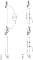
- FIG 6 shows an illustrative environment in which swarm drones 105 transmit data to the master drone 110, in which the data transmissions are received at the master drone's antennae 605 at varying angles.
- the known degree in which data transmissions are received at the master drone can be utilized as an additional tool to identify a precise location of the swarm drone in the physical environment.
- the master drone is configured with massive MIMO, the number of antennae is increased to provide greater detail as to the precise angular direction of the received signals.
- FIG 7 shows an illustrative cut-out 610 of the received signals at the antennae of FIG 6 , in which the direction of arrival (DoA) is determined at various antennae.
- DoA direction of arrival
- the varying angles among the antennae can collectively be utilized to determine a precise direction from which the signals were received.
- FIGs 8 and 9 show illustrative environments 800 and 900, respectively, in which master drones can determine a location for swarm drones using, for example, ToA and DoA as discussed above.
- Table 805 shows the representations of the master drones, swarm drones, and the determined distance from the master drone.
- the master drones when the master drones are deployed to create an ad-hoc 5G network, the master drones can utilize the 5G technologies to determine a precise location for swarm drones in the physical environment.
- FIGs 8 and 9 respectively show examples in which three and four master drones are utilized to triangulate the swarm drone's precise location using the determined distance of the swarm drone from each respective master drone.
- FIG 10 shows illustrative hardware and configurations of a swarm drone 105 in simplified form.
- the swarm drone can include a body 1005 which includes a frame 1010, arms 1015, and a motion component (e.g., propellers, wheels, tank treads, etc.) 1020 which, depending on the configuration, may be connected to the arms and used by the swarm drone to maneuver.
- a motion component e.g., propellers, wheels, tank treads, etc.
- discussion and embodiments herein may reference an airborne swarm drone, other methods of motion for swarm drones are also possible including ground travel or a hybrid of ground and air.
- Electrical components installed within the swarm drone include a battery 1025, motor 1030, and system hardware 1035 which includes one or more processors 1040, memory 1045, sensors 1050, radio transceiver 1055 with 5G capabilities 1060, and antennae with a massive MIMO configuration 1065.
- FIG 11 shows illustrative sensors 1050 which can be installed in and utilized by the swarm drone 105.
- exemplary sensors can include a global positioning system (GPS) 1105, air quality sensor 1110, Ultraviolet (UV) light detector 1115, camera 1120, thermometer 1125, magnetometer 1130, microphone 1135, carbon monoxide detector 1140, smoke detector 1145, altimeter 1150, inertial measurement unit 1155, proximity sensor 1160, barometer 1165, light sensor 1170, and depth sensor 1175.
- GPS global positioning system
- FIG 12 shows an illustrative embodiment in which the respective swarm drones 105 are configured with specific sensors for deployment.
- the respective swarm drones are configured with a camera and smoke detector.
- the respective drones can either detect smoke or capture photos or video while the drone navigates the area.
- FIG 13 shows an illustrative diagram in which the respective swarm drones 105 are assigned specific tasks, in which the sensors employed enable execution of the tasks.
- the task is to generate a structural layout of a physical environment, in which exemplary sensors which can enable execution of this task include the camera 1120 and depth sensor 1175.
- the task is to identify hazardous areas which may be inflicted with fire, in which exemplary sensors which can enable execution of this task include the smoke detector 1145 and thermometer 1125.
- the implementation of sensors allows the swarm drones to create a map of a physical environment with precise locations associated with each piece of collected sensor data. Alternatively, the created map may overlay an existing map of the physical environment, in which the created map can update aspects of the existing map including structures and environmental information picked up by the sensors (e.g., locations of carbon monoxide).
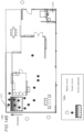
- FIGs 14A and B show respective illustrative environments 1400 and 1450 in which an ad-hoc deployable 5G network is created using the flexibly and rapidly deployed master drones, which are spread about the periphery of the building 1405.
- the master drones provide the benefit of 5G network capabilities to thereby develop a detailed map of the building's environment, negative space, and characteristics.
- the master and swarm drones can leverage the ad-hoc 5G capabilities and techniques for real-time precise localization of the swarm drones relative to the master drones ( FIGs 2-9 ).
- sensory data collected by the swarm drones can be assigned precise locations within the physical environment in which the swarm drones are deployed.
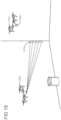
- FIG 15 shows two different scenarios in which locations for points are determined for placement in a generated map, which include remote point locations 1515 and local point locations 1520.
- Swarm drone 1505 is configured with sensors which scan the physical environment, such as the structural layout of the environment, in which the scanned points are locations remote from the swarm drone. Accordingly, the specific location of these points is to be determined so that an accurate map is generated of the environment.
- the swarm drone may be configured with sensory and positioning equipment to determine the position of the collected points and data within the physical environment.
- a depth sensor can be utilized as a complimentary sensor device to operate in conjunction with a primary sensor in order to identify the precise location for data collected by the primary sensor.
- the depth sensor can be aligned with and directed to the same location as a camera in order to pick up the precise location from which the data was collected by the camera.
- Other sensory devices which collect remote data can also use a depth sensor and the like to determine precise locations for each piece of collected data.
- the data collected by the depth sensor can be used to generate a point cloud structure, in which the data collected by the primary sensor is associated with each point in the point cloud structure.
- FIG 15 shows an example of a swarm drone collecting remote point locations 1515 for each instance of collected data in the physical environment.
- the distance between remote point locations can vary. For example, if time is of the essence, then greater distances between points can be used to expedite the scan of the physical environment. In another embodiment, if no relevant data is detected (e.g., no smoke), then greater distance can exist between points during the scan, whereas when relevant elements are detected, then the swarm drone can reduce the distance between scans to collect a sufficient number of accurate and precise points of data. Accordingly, the distance between points may be contingent on and automatically adjust according to a sliding scale based on detected sensor levels.
- FIG 15 shows an illustrative embodiment in which local point locations 1520 are determined for local sensors on the swarm drone 1510.
- certain sensors may operate and collect data without extending beyond the sensor itself (e.g., a thermometer); therefore, techniques to identify the precise location within the physical environment are implemented. Since the precise location of the swarm drone is known, the positioning of the sensor can be static and known to the swarm drone and/or the master drone. For example, the swarm drone's sensor may be a fixed location twenty degrees south and two inches from the center of the swarm drone's body.
- local points collected by local sensors are assigned locations based on the identified location of the swarm drone and adjusted according to the fixed location of the sensor relative to the identified precise location for the swarm drone (e.g., the center of the swarm drone's body).
- the swarm drones may be configured to operate autonomously such that the swarm drones traverse the environment without manual operation.
- cameras, depth sensors (e.g., LIDAR), proximity sensors, and other autonomous technologies are utilized by the swarm drone to ascertain its location in the physical environment.
- Autonomous movement by the swarm drone may be useful when the layout of the physical environment is unknown and elements hazardous for humans are present, such as fire.
- the swarm drones may be configured for external and manual control by a user in which the swarm drones are paired with a remote control or mobile computing device controllable by a user ( FIG 22 ).
- the swarm drones may be configured with a combination of independent and human-guided behaviors.
- FIG 14A illustratively shows two swarm drones which are deployed to collect data pertaining to the structural layout of the building's physical environment.
- These drones may be configured with depth sensors, cameras, and the like to capture an accurate map of the environment, including walls, floors, ceilings, and interior objects such as furniture, toys, animals, people, etc.
- FIG 14A also representatively shows a third swarm drone assigned the task of fire detection.
- This swarm drone may be configured with a smoke detector, thermometer, and the like to detect indications of a fire or other harmful elements.
- the combination of precise localization for the swarm drones and the collected sensory data provides a detailed map of all aspects for the physical environment. For example, in the illustrative area 1410 in the building 1405, the swarm drone can identify the gradual increase of smoke while traversing the area, which is graphically depicted as transitioning from white (no or low levels detected) to gray to black (high levels detected). This information is included in the created map so that users can know specifically where harmful elements exist.
- the fire detection swarm drone may be expendable as shown in FIG 14A .
- the swarm drone may be configured to travel as far as possible into the hazardous elements until the swarm drone becomes overheated, engulfed in flames, or destroyed.
- some swarm drones may be configured to navigate (e.g., turn left or right) or retreat when unsafe conditions, such as fire, are detected, some swarm drones may be configured to follow the path toward the unsafe conditions.
- the fire detection swarm drones can continue to travel toward the dangerous elements while collecting and transmitting the real-time data for generation of the map. This information can then be harnessed by fire professionals to focus their efforts.
- the fire professionals and fire responders who enter the scene can use the ad-hoc 5G network.
- the fire professionals can traverse the environment with personal computing devices which connect to the 5G ad-hoc network. This can enable location detection of the first responders relative to the generated map and allow the users to see their location. If the swarm drones are still scanning the environment (e.g., remaining unscanned areas or an updated subsequent scan being performed), the first responders can continue to receive updated map information in real time.
- FIG 14B illustratively shows a scenario in which dozens of swarm drones may be deployed to navigate and scan the building which thereby causes redundancy in localization and gathered sensor data to increase the confidence value for each point.
- the deployment of numerous swarm drones facilitates the real-time capture and mapping of the physical environment for use by professionals.
- Data pairs are developed using the collected sensor data and corresponding location data for the swarm drones which can be utilized to generate detailed and precise maps of the physical environment with high confidence that a scanned location is within centimeters of its real-world location.
- overlap and repeated scans of points by the multiple drones increase the confidence value associated with respective points.
- Localization redundancy and scan redundancy by the swarm drones and increased confidence for points facilitate the precise mapping and increased reliability of locations for the points in the physical environment.
- FIG 14B shows a scenario in which the swarm drones may be configured for traveling to relevant areas in which a relevant element has been identified (i.e., an element which the swarm drones are configured to detect).
- the additional swarm drones may each be configured to detect smoke or other fire-related elements which can be used by the master drones in building the map.
- the master drones can direct one or more swarm drones to a relevant area, such as area 1410, when another swarm drone identifies an element, such as high temperatures.
- the swarm drones can communicate with each other when the sensor for a swarm drone picks up an element, which thereby causes remote swarm drones to navigate to that area as well.
- the remote swarm drones may temporarily scan the area and then return to their previous locations to finish scanning the entire defined area. This configuration of the swarm drones can expedite the process of scanning the physical environment, which can be beneficial in dangerous situations for which it is desirable for professionals to swiftly address. As discussed in further detail below with respect to FIG 16 , the master drones shown in FIG 14B shifted positions to increase functionality and reception with the swarm drones at the relevant area 1410.
- swarm drones can be deployed to the building to identify ingress and egress routes. Localization redundancy and scan redundancy among multiple swarm drones that indicates an entranceway or staircase is free from smoke and heat provides increased confidence that humans can ingress and egress those areas.
- Confidence values associated with the sensor data can be based on the data collected at respective master drones as well. For example, if multiple master drones have localization and sensor information for distinct swarm drones, then the collective similarities among the data collected across the master drones also provide increased confidence in the data. Thus, confidence in collected data can be based on the redundancy of data collected by swarm drones, and additionally or alternatively based on similarities of data collected across master drones.
- FIG 16 illustratively shows a taxonomy of operations performable by the master drones 1605.
- Operations include receive and collect data from the swarm drones 1610, build map of the physical environment 1615, associate primary sensor data (e.g., structural layout) with location points (e.g., point cloud structure) developed from complimentary sensor devices (e.g., depth sensor) 1620, transmit and consolidate data to a single master drone to collect and generate the map 1625, transmit and consolidate data to a remote service to collect and generate the map 1630, autonomously maneuver to improve location detection of the swarm drones 1635, autonomously maneuver to maintain a functional range with swarm drones 1640, autonomously maneuver in conjunction with other master drones to improve location detection of swarm drones (e.g., triangulation) 1645, disregard the sensor data if an identified location of the swarm drone or its collected data does not satisfy a threshold confidence value 1650
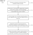
- FIG 17 is a flowchart of an illustrative method 1700 in which a swarm drone collects environmental data. Unless specifically stated, methods or steps shown in the flowcharts and described in the accompanying text are not constrained to a particular order or sequence. In addition, some of the methods or steps thereof can occur or be performed concurrently and not all the methods or steps have to be performed in a given implementation depending on the requirements of such implementation and some methods or steps may be optionally utilized.
- a plurality of swarm drones traverse a physical environment.
- using one or more sensors respectively coupled to the swarm drones scan the physical environment to generate environmental data that is associated with a given location in the physical environment.
- the swarm drones communicate with a remote computing device over respective one or more 5G network links in real time.
- the swarm drones enable the remote computing device to determine respective current locations of one or more swarm drones over the 5G network links.
- the plurality of swarm drones are deployed within the physical environment to enable utilization of redundant localization and environmental data.
- FIG 18 is a flowchart of an illustrative method 1800 in which, in step 1805, a mobile master drone utilizes a 5G radio transceiver configured for communications with a mobile swarm drone and at least one 5G cell having a fixed position.
- a location is identified for the master drone based on communications exchanged between the master drone and the at least one 5G cell.
- locations for a swarm drone are dynamically identified relative to the master drones as the swarm drone traverses a physical space.
- a spatial map of the physical environment is generated using the dynamically identified locations for the swarm drones.
- FIG 19 is a flowchart of an illustrative method 1900 in which a computing device receives real-time sensor data and generates a map using the received sensor data.
- sensor data is received which is collected from a swarm drone using 5G specific technology in real time as the swarm drone traverses the physical environment.
- a location of the swarm drone is identified that corresponds with each received instance of real-time sensor data using 5G specific technology in real time.
- the received real-time sensor data and the corresponding location for each instance of real-time sensor data is stored.
- a map of the physical environment is generated using the stored real-time sensor data and corresponding locations.
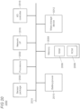
- FIG 20 shows an illustrative architecture 2000 for a device capable of executing the various components described herein for providing precision mapping for autonomous devices.
- the architecture 2000 illustrated in FIG 20 shows a system architecture that may be adapted for a swarm drone.
- the architecture 2000 illustrated in FIG 20 includes one or more processors 2002 (e.g., central processing unit, graphic processing units, etc.), a system memory 2004, including RAM (random access memory) 2006 and ROM (read only memory) 2008, and a system bus 2010 that operatively and functionally couples the components in the architecture 2000.
- processors 2002 e.g., central processing unit, graphic processing units, etc.
- system memory 2004, including RAM (random access memory) 2006 and ROM (read only memory) 2008 operatively and functionally couples the components in the architecture 2000.
- a basic input/output system containing the basic routines that help to transfer information between elements within the architecture 2000, such as during startup, is typically stored in the ROM 2008.
- the architecture 2000 further includes a mass storage device 2012 for storing software code or other computer-executed code that is utilized to implement applications, the file system, and the operating system.
- the mass storage device 2012 is connected to the processor 2002 through a mass storage controller (not shown) connected to the bus 2010.
- the mass storage device 2012 and its associated computer-readable storage media provide non-volatile storage for the architecture 2000.
- computer-readable storage media can be any available storage media that can be accessed by the architecture 2000.
- the architecture 2000 further supports a sensor package 2030 comprising one or more sensors or components that are configured to detect parameters that are descriptive of the environment.
- the sensors may be positioned directly or indirectly on the swarm drone's body.
- the sensors may be configured to run continuously, or periodically.
- the architecture further supports power and/or battery components (collectively identified by reference numeral 2015).
- one or more batteries or power packs may be rechargeable or replaceable to facilitate portability, mobility, and re-use.
- computer-readable storage media may include volatile and non-volatile, removable and non-removable media implemented in any method or technology for storage of information such as computer-readable instructions, data structures, program modules, or other data.
- computer-readable media includes, but is not limited to, RAM, ROM, EPROM (erasable programmable read only memory), EEPROM (electrically erasable programmable read only memory), Flash memory or other solid state memory technology, CD-ROM, DVDs, HD-DVD (High Definition DVD), Blu-ray, or other optical storage, magnetic cassettes, magnetic tape, magnetic disk storage or other magnetic storage devices, or any other medium which can be used to store the desired information and which can be accessed by the architecture 2000.
- the architecture 2000 may operate in a networked environment using logical connections to remote computers through a network.
- the architecture 2000 may connect to the network through a network interface unit 2016 connected to the bus 2010. It may be appreciated that the network interface unit 2016 also may be utilized to connect to other types of networks and remote computer systems.
- the architecture 2000 also may include an input/output controller 2018 for receiving and processing input from a number of other devices, including a keyboard, mouse, touchpad, touchscreen, control devices such as buttons and switches or electronic stylus (not shown in FIG 20 ). Similarly, the input/output controller 2018 may provide output to a display screen, user interface, a printer, or other type of output device (also not shown in FIG 20 ).
- the architecture 2000 may include a voice recognition unit (not shown) to facilitate user interaction with a device supporting the architecture through voice commands, a natural language interface, or through voice interactions with a personal digital assistant (such as the Cortana ® personal digital assistant provided by Microsoft Corporation).
- the architecture 2000 may include a gesture recognition unit (not shown) to facilitate user interaction with a device supporting the architecture through sensed gestures, movements, and/or other sensed inputs.
- the software components described herein may, when loaded into the processor 2002 and executed, transform the processor 2002 and the overall architecture 2000 from a general-purpose computing system into a special-purpose computing system customized to facilitate the functionality presented herein.
- the processor 2002 may be constructed from any number of transistors or other discrete circuit elements, which may individually or collectively assume any number of states. More specifically, the processor 2002 may operate as a finite-state machine, in response to executable instructions contained within the software modules disclosed herein. These computer-executable instructions may transform the processor 2002 by specifying how the processor 2002 transitions between states, thereby transforming the transistors or other discrete hardware elements constituting the processor 2002.
- Encoding the software modules presented herein also may transform the physical structure of the computer-readable storage media presented herein.
- the specific transformation of physical structure may depend on various factors, in different implementations of this description. Examples of such factors may include, but are not limited to, the technology used to implement the computer-readable storage media, whether the computer-readable storage media is characterized as primary or secondary storage, and the like.
- the computer-readable storage media is implemented as semiconductor-based memory
- the software disclosed herein may be encoded on the computer-readable storage media by transforming the physical state of the semiconductor memory.
- the software may transform the state of transistors, capacitors, or other discrete circuit elements constituting the semiconductor memory.
- the software also may transform the physical state of such components in order to store data thereupon.
- the computer-readable storage media disclosed herein may be implemented using magnetic or optical technology.
- the software presented herein may transform the physical state of magnetic or optical media, when the software is encoded therein. These transformations may include altering the magnetic characteristics of particular locations within given magnetic media. These transformations also may include altering the physical features or characteristics of particular locations within given optical media to change the optical characteristics of those locations. Other transformations of physical media are possible without departing from the scope and spirit of the present description, with the foregoing examples provided only to facilitate this discussion.
- the architecture 2000 may include other types of computing devices, including wearable devices, handheld computers, embedded computer systems, smartphones, PDAs, and other types of computing devices known to those skilled in the art. It is also contemplated that the architecture 2000 may not include all of the components shown in FIG 20 , may include other components that are not explicitly shown in FIG 20 , or may utilize an architecture completely different from that shown in FIG 20 .
- FIG 21 is a simplified block diagram of an illustrative computer system 2100 such as a server which may be used to implement the present precision mapping using autonomous devices. Additionally, the master drone may be configured as such in order to process the sensor data and build the map of the physical environment.
- Computer system 2100 includes a processor 2105, a system memory 2111, and a system bus 2114 that couples various system components including the system memory 2111 to the processor 2105.
- the system bus 2114 may be any of several types of bus structures including a memory bus or memory controller, a peripheral bus, or a local bus using any of a variety of bus architectures.
- the system memory 2111 includes read only memory (ROM) 2117 and random access memory (RAM) 2121.
- a basic input/output system (BIOS) 2125 containing the basic routines that help to transfer information between elements within the computer system 2100, such as during startup, is stored in ROM 2117.
- the computer system 2100 may further include a hard disk drive 2128 for reading from and writing to an internally disposed hard disk (not shown), a magnetic disk drive 2130 for reading from or writing to a removable magnetic disk 2133 (e.g., a floppy disk), and an optical disk drive 2138 for reading from or writing to a removable optical disk 2143 such as a CD (compact disc), DVD (digital versatile disc), or other optical media.
- the hard disk drive 2128, magnetic disk drive 2130, and optical disk drive 2138 are connected to the system bus 2114 by a hard disk drive interface 2146, a magnetic disk drive interface 2149, and an optical drive interface 2152, respectively.
- the drives and their associated computer-readable storage media provide non-volatile storage of computer-readable instructions, data structures, program modules, and other data for the computer system 2100.
- this illustrative example includes a hard disk, a removable magnetic disk 2133, and a removable optical disk 2143
- other types of computer-readable storage media which can store data that is accessible by a computer such as magnetic cassettes, Flash memory cards, digital video disks, data cartridges, random access memories (RAMs), read only memories (ROMs), and the like may also be used in some applications of the present precision mapping using autonomous devices.
- the term computer-readable storage media includes one or more instances of a media type (e.g., one or more magnetic disks, one or more CDs, etc.).
- the phrase "computer-readable storage media" and variations thereof are non-transitory and do not include waves, signals, and/or other transitory and/or intangible communication media.
- a number of program modules may be stored on the hard disk, magnetic disk, optical disk, ROM 2117, or RAM 2121, including an operating system 2155, one or more application programs 2157, other program modules 2160, and program data 2163.
- a user may enter commands and information into the computer system 2100 through input devices such as a keyboard 2166 and pointing device 2168 such as a mouse.
- Other input devices may include a microphone, joystick, game pad, satellite dish, scanner, trackball, touchpad, touchscreen, touch-sensitive device, voice-command module or device, user motion or user gesture capture device, or the like.
- serial port interface 2171 that is coupled to the system bus 2114, but may be connected by other interfaces, such as a parallel port, game port, or universal serial bus (USB).
- a monitor 2173 or other type of display device is also connected to the system bus 2114 via an interface, such as a video adapter 2175.
- wearable devices and personal computers can typically include other peripheral output devices (not shown), such as speakers and printers.
- the illustrative example shown in FIG 21 also includes a host adapter 2178, a Small Computer System Interface (SCSI) bus 2183, and an external storage device 2176 connected to the SCSI bus 2183.
- SCSI Small Computer System Interface
- the computer system 2100 is operable in a networked environment using logical connections to one or more remote computers, such as a remote computer 2188.
- the remote computer 2188 may be selected as a personal computer, a server, a router, a network PC, a peer device, or other common network node, and typically includes many or all of the elements described above relative to the computer system 2100, although only a single representative remote memory/storage device 2190 is shown in FIG 21 .
- the logical connections depicted in FIG 21 include a local area network (LAN) 2193 and a wide area network (WAN) 2195.
- LAN local area network
- WAN wide area network
- the computer system 2100 When used in a LAN networking environment, the computer system 2100 is connected to the local area network 2193 through a network interface or adapter 2196. When used in a WAN networking environment, the computer system 2100 typically includes a broadband modem 2198, network gateway, or other means for establishing communications over the wide area network 2195, such as the Internet.
- the broadband modem 2198 which may be internal or external, is connected to the system bus 2114 via a serial port interface 2171.
- program modules related to the computer system 2100, or portions thereof may be stored in the remote memory storage device 2190. It is noted that the network connections shown in FIG 21 are illustrative and other means of establishing a communications link between the computers may be used depending on the specific requirements of an application of the present precision mapping using autonomous devices.
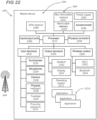
- FIG 22 is a functional block diagram of an illustrative computing device 2205 such as a mobile phone, smartphone, or other computing device including a variety of optional hardware and software components, shown generally at 2202.
- the computing device 2205 may be utilized in embodiments in which the swarm drones are manually controllable, or for users to view a real-time map of that which is generated by the swarm drone, master drone, and remote server.
- Any component 2202 in the mobile device can communicate with any other component, although, for ease of illustration, not all connections are shown.
- the mobile device can be any of a variety of computing devices (e.g., cell phone, smartphone, handheld computer, PDA, etc.) and can allow wireless two-way communications with one or more mobile communication networks 2204, such as a cellular or satellite network.
- mobile communication networks 2204 such as a cellular or satellite network.
- the illustrated device 2205 can include a controller or processor 2210 (e.g., signal processor, microprocessor, microcontroller, ASIC (Application Specific Integrated Circuit), or other control and processing logic circuitry) for performing such tasks as signal coding, data processing, input/output processing, power control, and/or other functions.
- An operating system 2212 can control the allocation and usage of the components 2202, including power states, above-lock states, and below-lock states, and provides support for one or more application programs 2214.
- the application programs can include common mobile computing applications (e.g., image-capture applications, e-mail applications, calendars, contact managers, web browsers, messaging applications), or any other computing application.
- the illustrated device 2205 can include memory 2220.
- Memory 2220 can include non-removable memory 2222 and/or removable memory 2224.
- the non-removable memory 2222 can include RAM, ROM, Flash memory, a hard disk, or other well-known memory storage technologies.
- the removable memory 2224 can include Flash memory or a Subscriber Identity Module (SIM) card, which is well known in GSM (Global System for Mobile communications) systems, or other well-known memory storage technologies, such as "smart cards.”
- SIM Subscriber Identity Module
- the memory 2220 can be used for storing data and/or code for running the operating system 2212 and the application programs 2214.
- Example data can include web pages, text, images, sound files, video data, or other data sets to be sent to and/or received from one or more network servers or other devices via one or more wired or wireless networks.
- the memory 2220 may also be arranged as, or include, one or more computer-readable storage media implemented in any method or technology for storage of information such as computer-readable instructions, data structures, program modules or other data.
- computer-readable media includes, but is not limited to, RAM, ROM, EPROM, EEPROM, Flash memory or other solid state memory technology, CD-ROM (compact-disc ROM), DVD, (Digital Versatile Disc) HD-DVD (High Definition DVD), Blu-ray, or other optical storage, magnetic cassettes, magnetic tape, magnetic disk storage or other magnetic storage devices, or any other medium which can be used to store the desired information and which can be accessed by the device 2205.
- the memory 2220 can be used to store a subscriber identifier, such as an International Mobile Subscriber Identity (IMSI), and an equipment identifier, such as an International Mobile Equipment Identifier (IMEI). Such identifiers can be transmitted to a network server to identify users and equipment.
- the device 2205 can support one or more input devices 2230- such as a touchscreen 2232; microphone 2234 for implementation of voice input for voice recognition, voice commands, and the like; camera 2236; physical keyboard 2238; trackball 2240; and/or proximity sensor 2242; and one or more output devices 2250- such as a speaker 2252 and one or more displays 2254.
- Other input devices (not shown) using gesture recognition may also be utilized in some cases.
- Other possible output devices can include piezoelectric or haptic output devices. Some devices can serve more than one input/output function. For example, touchscreen 2232 and display 2254 can be combined into a single input/output device.
- a wireless modem 2260 can be coupled to an antenna (not shown) and can support two-way communications between the processor 2210 and external devices, as is well understood in the art.
- the modem 2260 is shown generically and can include a cellular modem for communicating with the mobile communication network 2204 and/or other radio-based modems (e.g., Bluetooth 2264 or Wi-Fi 2262).
- the wireless modem 2260 is typically configured for communication with one or more cellular networks, such as a GSM network for data and voice communications within a single cellular network, between cellular networks, or between the device and a public switched telephone network (PSTN).
- GSM Global System for Mobile communications
- PSTN public switched telephone network
- the device can further include at least one input/output port 2280, a power supply 2282, a satellite navigation system receiver 2284, such as a GPS receiver, an accelerometer 2296, a gyroscope (not shown), and/or a physical connector 2290, which can be a USB port, IEEE 1394 (FireWire) port, and/or an RS-232 port.
- a satellite navigation system receiver 2284 such as a GPS receiver
- an accelerometer 2296 such as a GPS receiver
- a gyroscope not shown
- a physical connector 2290 which can be a USB port, IEEE 1394 (FireWire) port, and/or an RS-232 port.
- the illustrated components 2202 are not required or all-inclusive, as any components can be deleted and other components can be added.
Landscapes
- Engineering & Computer Science (AREA)
- Physics & Mathematics (AREA)
- General Physics & Mathematics (AREA)
- Computer Networks & Wireless Communication (AREA)
- Signal Processing (AREA)
- Remote Sensing (AREA)
- Radar, Positioning & Navigation (AREA)
- Theoretical Computer Science (AREA)
- Geometry (AREA)
- Software Systems (AREA)
- Computer Vision & Pattern Recognition (AREA)
- Computer Graphics (AREA)
- Aviation & Aerospace Engineering (AREA)
- Automation & Control Theory (AREA)
- Control Of Position, Course, Altitude, Or Attitude Of Moving Bodies (AREA)
- Testing And Monitoring For Control Systems (AREA)
- Traffic Control Systems (AREA)
Claims (14)
- Verfahren, das ein Netzwerk der fünften Generation (5G) einschließlich einer festen Infrastruktur, die einen Backhaul-Zugang zu einem Weitverkehrsnetzwerk bereitstellt, für eine Präzisionskartierung einer physischen Umgebung unter Verwendung einer Vielzahl von Schwarmdrohnen (105) verwendet, umfassend:Durchqueren der physischen Umgebung mit der Vielzahl von Schwarmdrohnen (105);Verwenden eines oder mehrerer Sensoren (1050), die jeweils mit jeder der Schwarmdrohnen (105) gekoppelt sind, Scannen der physischen Umgebung, um Umgebungsdaten zu erzeugen, die einem bestimmten Ort in der physischen Umgebung zugeordnet sind;Kommunizieren mit einer entfernten Hauptdrohne (110) über jeweilige eine oder mehrere 5G-Netzwerkverbindungen in Echtzeit, wobei die Kommunikation die erzeugten Umgebungsdaten einschließt;Ermöglichen, dass die entfernte Hauptdrohne (110) die jeweiligen aktuellen Standorte einer oder mehrerer der Schwarmdrohnen (105) unter Verwendung der Kommunikation über die 5G-Netzwerkverbindungen bestimmt, wobei die entfernte Hauptdrohne (110) angeordnet ist, um mit der festen 5G-Infrastruktur (115) zu kommunizieren, und weiter als ein mobiler 5G-Zugangspunkt für die Vielzahl der Schwarmdrohnen (105) angeordnet ist;Einsetzen der Vielzahl der Schwarmdrohnen (105) innerhalb der physischen Umgebung, um die Nutzung redundanter Lokalisierungs- und Umgebungsdaten zu ermöglichen, um dadurch die Präzision und Vertrauenswürdigkeit der erzeugten Umgebungsdaten auf einer Basis pro Standort innerhalb der physischen Umgebung zu erhöhen; undAnpassen einer Konfiguration des 5G-Netzwerks durch autonomes Ändern von Standorten einer oder mehrerer Hauptdrohnen in Bezug auf die feste 5G-Infrastruktur (115) und auf die Schwarmdrohne, um dadurch die Konnektivität zu optimieren und die Standorterkennung der einen oder mehreren Schwarmdrohnen durch die entfernte Hauptdrohne zu verbessern.
- Verfahren nach Anspruch 1, wobei die Umgebungsdaten zur Erstellung einer Karte der physischen Umgebung verwendet werden.
- Verfahren nach Anspruch 2, wobei die Schwarmdrohnen mit einer Vielzahl von 5G-Zugangspunkten in Kommunikation stehen, und das Verfahren weiter umfasst:Bestimmen einer Ankunftszeit (ToA) für Signale, die von den jeweiligen Schwarmdrohnen an einem oder mehreren Zugangspunkten der Vielzahl von Zugangspunkten empfangen werden;Verwenden der ToA, um den Standort für die jeweiligen Schwarmdrohnen in der physischen Umgebung zu bestimmen; undErstellen der Karte der physischen Umgebung unter Verwendung des durch die ToA-Bestimmung ermittelten Standorts.
- Verfahren nach Anspruch 1, wobei die physische Umgebung ein definierter Raum ist und eine äußere Umgebung die Umgebung außerhalb der physischen Umgebung ist, und eine oder beide, die physische Umgebung oder die äußere Umgebung, eine Vielzahl von Zugangspunkten umfassen, die 5G-Netzwerkkonnektivität bereitstellen und mit den Schwarmdrohnen in Kommunikation stehen, und die Vielzahl von Zugangspunkten den Standort der jeweiligen Schwarmdrohnen auf der Grundlage der erfassten Entfernung der Schwarmdrohnen zu jedem Zugangspunkt triangulieren.
- Verfahren nach Anspruch 1, wobei der eine oder die mehreren Sensoren, die von den Schwarmdrohnen verwendet werden, ein globales Positionierungssystem, einen Luftqualitätssensor, einen Ultraviolettlichtdetektor, eine Kamera, ein Thermometer, ein Magnetometer, ein Mikrofon, einen Kohlenmonoxiddetektor, einen Rauchdetektor, einen Höhenmesser, eine Trägheitsmesseinheit, einen Näherungssensor, ein Barometer, einen Lichtsensor oder einen Tiefensensor umfassen.
- Verfahren nach Anspruch 1, wobei das Einsetzen unter Verwendung autonomer Operationen einer oder mehrerer der Schwarmdrohnen, gesteuerter Operationen einer oder mehrerer Schwarmdrohnen oder Kombinationen aus autonomen und gesteuerten Operationen durchgeführt wird.
- Verfahren nach Anspruch 6,
wobei die gesteuerten Operationen auf Steuersignale reagieren, die von einer Hauptdrohne empfangen werden. - Verfahren nach Anspruch 1, weiter umfassend: Erzeugen einer räumlichen Karte einer physischen Umgebung unter Verwendung dynamisch identifizierter Standorte für die Schwarmdrohnen (105) relativ zur Hauptdrohne (110), wobei die erzeugte räumliche Karte Informationen enthält, die durch mit der Schwarmdrohne gekoppelte Sensoren erhalten werden, und jede Information einem dynamisch identifizierten Standort für die Schwarmdrohne innerhalb der physischen Umgebung zugeordnet ist.
- Verfahren nach Anspruch 8, wobei die von der Schwarmdrohne erhaltenen Informationen entweder verwendet oder außer Acht gelassen werden, wenn das Vertrauen in den Standort der Schwarmdrohne einen Schwellenwert erfüllt bzw. nicht erfüllt.
- Verfahren nach Anspruch 1, weiter umfassend das Einsetzen der Hauptdrohne in einem Ad-hoc-5G-Netzwerk, wobei eine Einsatzkonfiguration des Ad-hoc-5G-Netzwerks so angepasst wird, dass Standorte der Hauptdrohne geändert werden, um eine funktionale Reichweite mit der Schwarmdrohne aufrecht zu erhalten, während die Schwarmdrohne die physische Umgebung durchquert.
- Verfahren nach Anspruch 1, wobei die Einsatzkonfiguration des Ad-hoc-5G-Netzwerks so angepasst wird, dass Standorte der Hauptdrohne geändert werden, um die Standorterkennungsmerkmale für die Schwarmdrohne zu verbessern, wobei die Erkennungsmerkmale Ankunftszeit, Ankunftsrichtung, Sichtlinie und Triangulation einschließen.
- Verfahren nach Anspruch 1, wobei die Einsatzkonfiguration des Ad-hoc-5G-Netzwerks so angepasst wird, dass Standorte der Hauptdrohne relativ zu einer oder mehreren zusätzlichen Hauptdrohnen, die im Ad-hoc-5G-Netzwerk betrieben werden, geändert werden, um die Standorterkennung für die Schwarmdrohne zu verbessern.
- Verfahren nach Anspruch 12, wobei die Einsatzkonfiguration des Ad-hoc-5G-Netzwerks so angepasst wird, dass die Standorte der Hauptdrohne geändert werden, wobei die Hauptdrohne ihren Standort relativ zu der einen oder mehreren zusätzlichen Hauptdrohnen anpasst, um die Triangulation der Schwarmdrohne zu verbessern.
- Eine oder mehrere hardwarebasierte, nicht transitorische, computerlesbare Speichervorrichtungen (2012), die Anweisungen speichern, die, wenn sie von einem oder mehreren Prozessoren (2002) ausgeführt werden, die in einer mobilen Hauptdrohne (110) angeordnet sind, die Hauptdrohne (110) veranlassen zum:Eingesetztwerden in einem Ad-hoc-Netzwerk der fünften Generation 5G, Kommunizieren mit einer festen 5G-Infrastruktur und Bereitstellen eines mobilen 5G-Zugangspunkts für eine Vielzahl von Schwarmdrohnen, die innerhalb einer physischen Umgebung eingesetzt werden, um redundante Standort- und Umgebungsdaten zu erzeugen;Bestimmen aktueller Standorte einer oder mehrerer Schwarmdrohnen (105) mithilfe der Kommunikation über die 5G-Netzwerkverbindungen;Lenken einer oder mehrerer Schwarmdrohnen zu einem bestimmten Gebiet;Anpassen einer Konfiguration des 5G-Netzwerks durch autonomes Ändern der Standorte in Bezug auf die feste 5G-Infrastruktur (115) und auf die Schwarmdrohne, um dadurch die Konnektivität zu optimieren und die Standorterkennung der einen oder mehreren Schwarmdrohnen durch die entfernte Hauptdrohne zu verbessern.
Applications Claiming Priority (3)
| Application Number | Priority Date | Filing Date | Title |
|---|---|---|---|
| US201862674300P | 2018-05-21 | 2018-05-21 | |
| US15/989,916 US10909712B2 (en) | 2018-05-21 | 2018-05-25 | Precision mapping using autonomous devices |
| PCT/US2019/031922 WO2019226376A2 (en) | 2018-05-21 | 2019-05-13 | Precision mapping using autonomous devices |
Publications (2)
| Publication Number | Publication Date |
|---|---|
| EP3797342A2 EP3797342A2 (de) | 2021-03-31 |
| EP3797342B1 true EP3797342B1 (de) | 2023-06-28 |
Family
ID=68532641
Family Applications (1)
| Application Number | Title | Priority Date | Filing Date |
|---|---|---|---|
| EP19726282.7A Active EP3797342B1 (de) | 2018-05-21 | 2019-05-13 | Präzisionsabbildung mittels autonomer vorrichtungen |
Country Status (3)
| Country | Link |
|---|---|
| US (1) | US10909712B2 (de) |
| EP (1) | EP3797342B1 (de) |
| WO (1) | WO2019226376A2 (de) |
Cited By (1)
| Publication number | Priority date | Publication date | Assignee | Title |
|---|---|---|---|---|
| US12208930B1 (en) | 2023-11-01 | 2025-01-28 | T-Mobile Usa, Inc. | 5G-connected drone routing system capable of monitoring interior environments |
Families Citing this family (21)
| Publication number | Priority date | Publication date | Assignee | Title |
|---|---|---|---|---|
| US11487015B2 (en) | 2017-06-05 | 2022-11-01 | Bluehalo, Llc | Atmospheric characterization systems and methods |
| US10970924B2 (en) * | 2018-06-17 | 2021-04-06 | Foresight Ai Inc. | Reconstruction of a scene from a moving camera |
| CN114556133B (zh) * | 2019-10-15 | 2025-12-09 | 索尼半导体解决方案公司 | 测距设备及其光接收方法 |
| DE102020000663A1 (de) | 2020-01-31 | 2021-08-05 | Mbda Deutschland Gmbh | Verfahren zur Verbesserung einer Navigationsgüte durch aktive Gestaltung einer Bewegungsformation eines kollaborierenden Schwarms aus mobilen unbemannten Einheiten |
| US11075817B1 (en) * | 2020-05-08 | 2021-07-27 | International Business Machines Corporation | Context aware network capacity augmentation using a flying device |
| CN111650961A (zh) * | 2020-05-29 | 2020-09-11 | 西安理工大学 | 基于改进人工势场的5g网联无人机编队防碰撞方法 |
| US20210407302A1 (en) * | 2020-06-30 | 2021-12-30 | Sony Group Corporation | System of multi-drone visual content capturing |
| US20230314548A1 (en) * | 2020-08-31 | 2023-10-05 | Nanyang Technological University | Unmanned aerial vehicle and localization method for unmanned aerial vehicle |
| CN112880685A (zh) * | 2021-01-19 | 2021-06-01 | 中国人民解放军陆军边海防学院 | 无人机群对探测目标的联合定位方法 |
| US12094197B2 (en) * | 2021-06-10 | 2024-09-17 | Sony Group Corporation | Extraneous content removal from images of a scene captured by a multi-drone swarm |
| CN113359862B (zh) * | 2021-07-28 | 2023-05-16 | 北京理工大学 | 一种无人机进入封闭环境的控制方法及装置 |
| US20230055054A1 (en) * | 2021-08-23 | 2023-02-23 | Napco Security Technologies, Inc. | Security Communicator Dual Antenna System |
| CN114548148B (zh) * | 2022-01-11 | 2025-08-29 | 西安理工大学 | 三维空间中反无人机紫外光近距离探测识别方法 |
| CN114641095B (zh) * | 2022-03-10 | 2024-08-06 | 上海旷通科技有限公司 | 可自主飞行的5g室外型终端 |
| CN114610036B (zh) * | 2022-03-11 | 2024-08-13 | 中国人民解放军国防科技大学 | 一种基于自组织分组的目标围捕方法及相关设备 |
| US11733372B1 (en) * | 2022-03-28 | 2023-08-22 | Bluehalo, Llc | System and method for dynamic two-way ranging using unmanned aerial vehicles |
| US11693432B1 (en) | 2022-05-24 | 2023-07-04 | Bluehalo, Llc | System and method for autonomously controlling a set of unmanned aerial vehicles |
| US20240036153A1 (en) * | 2022-07-29 | 2024-02-01 | Mitchell Aaron Thornton | Systems and Methods for RF Emitter Location with Automatic UAS Array Reconfiguration |
| CN116680204B (zh) * | 2023-08-03 | 2023-11-14 | 中国人民解放军军事科学院国防科技创新研究院 | 一种基于4g网络的无人机集群载荷远程调试方法和系统 |
| CN120522689A (zh) * | 2025-05-20 | 2025-08-22 | 南京泰弘讯达科技有限公司 | 一种空地协同毫米波通感智能感知与决策系统 |
| US12608024B1 (en) * | 2025-07-08 | 2026-04-21 | Drone Operations LLC | Autonomous drone swarm system with AI-driven coordination and multi-modal sensor integration |
Family Cites Families (12)
| Publication number | Priority date | Publication date | Assignee | Title |
|---|---|---|---|---|
| US9075415B2 (en) | 2013-03-11 | 2015-07-07 | Airphrame, Inc. | Unmanned aerial vehicle and methods for controlling same |
| US9448073B2 (en) * | 2013-06-10 | 2016-09-20 | Google Inc. | System and method for assessing road quality using data collected from a mobile device |
| CN107531326B (zh) | 2015-03-12 | 2019-04-16 | 奈庭吉尔智慧系统公司 | 自动化无人机系统 |
| KR101685548B1 (ko) * | 2015-04-01 | 2016-12-12 | 고려대학교 산학협력단 | 드론 편대 제어 방법 |
| US10694155B2 (en) | 2015-06-25 | 2020-06-23 | Intel Corporation | Personal sensory drones |
| US9745060B2 (en) | 2015-07-17 | 2017-08-29 | Topcon Positioning Systems, Inc. | Agricultural crop analysis drone |
| US20170127606A1 (en) | 2015-11-10 | 2017-05-11 | Digi-Star, Llc | Agricultural Drone for Use in Controlling the Direction of Tillage and Applying Matter to a Field |
| GB2547416A (en) | 2016-02-10 | 2017-08-23 | Tyco Fire & Security Gmbh | A fire detection system |
| EP4047439A1 (de) * | 2016-06-21 | 2022-08-24 | Telefonaktiebolaget LM Ericsson (publ) | Verfahren zum lenken unbemannter luftfahrzeuge |
| US11356798B2 (en) | 2016-07-01 | 2022-06-07 | Intel Corporation | Internet-of-things swarm management |
| MX2019003894A (es) * | 2016-10-04 | 2019-09-04 | Walmart Apollo Llc | Sistemas y metodos para navegacion autonoma con dron. |
| US10470241B2 (en) * | 2016-11-15 | 2019-11-05 | At&T Intellectual Property I, L.P. | Multiple mesh drone communication |
-
2018
- 2018-05-25 US US15/989,916 patent/US10909712B2/en active Active
-
2019
- 2019-05-13 WO PCT/US2019/031922 patent/WO2019226376A2/en not_active Ceased
- 2019-05-13 EP EP19726282.7A patent/EP3797342B1/de active Active
Cited By (1)
| Publication number | Priority date | Publication date | Assignee | Title |
|---|---|---|---|---|
| US12208930B1 (en) | 2023-11-01 | 2025-01-28 | T-Mobile Usa, Inc. | 5G-connected drone routing system capable of monitoring interior environments |
Also Published As
| Publication number | Publication date |
|---|---|
| WO2019226376A3 (en) | 2020-01-02 |
| WO2019226376A2 (en) | 2019-11-28 |
| US10909712B2 (en) | 2021-02-02 |
| EP3797342A2 (de) | 2021-03-31 |
| US20190355145A1 (en) | 2019-11-21 |
Similar Documents
| Publication | Publication Date | Title |
|---|---|---|
| EP3797342B1 (de) | Präzisionsabbildung mittels autonomer vorrichtungen | |
| Alhafnawi et al. | A survey of indoor and outdoor uav-based target tracking systems: Current status, challenges, technologies, and future directions | |
| Motlagh et al. | Unmanned aerial vehicles for air pollution monitoring: A survey | |
| Wei et al. | UAV-assisted data collection for Internet of Things: A survey | |
| Mukherjee et al. | EdgeDrone: QoS aware MQTT middleware for mobile edge computing in opportunistic Internet of Drone Things | |
| Sharma et al. | A cooperative network framework for multi-UAV guided ground ad hoc networks | |
| US10834766B2 (en) | Unmanned vehicle controlling system and method of operating same | |
| Kim et al. | Coordinated trajectory planning for efficient communication relay using multiple UAVs | |
| Tuna et al. | An autonomous wireless sensor network deployment system using mobile robots for human existence detection in case of disasters | |
| Chowdhury et al. | RSS-based Q-learning for indoor UAV navigation | |
| Islam et al. | A path planning algorithm for collective monitoring using autonomous drones | |
| Phadke et al. | Increasing operational resiliency of uav swarms: An agent-focused search and rescue framework | |
| Abbas et al. | Integration of UAVs and FANETs in disaster management: A review on applications, challenges and future directions | |
| Awasthi et al. | Micro UAV Swarm for industrial applications in indoor environment: A systematic literature review | |
| Rasmussen et al. | Field experiment of a fully autonomous multiple UAV/UGS intruder detection and monitoring system | |
| Aminzadeh et al. | Multi-UAV cooperative search and coverage control in post-disaster assessment: experimental implementation | |
| CN112639735A (zh) | 计算量分配 | |
| Dah-Achinanon et al. | Search and rescue with sparsely connected swarms | |
| Varotto et al. | Active sensing for search and tracking: A review | |
| Ramos et al. | Advancing UAV swarm autonomy with ARCog-NET for task allocation, path planning, and formation control | |
| Chandran et al. | Heterogeneous multi-UAV ad-hoc networks for surveillance and wireless coverage in challenging terrain to enhance disaster missions | |
| Batistatos et al. | Uav swarm management platform for autonomous area and infrastructure inspection | |
| Areias et al. | A control and communications platform for procedural mission planning with multiple aerial drones | |
| Kumari et al. | Multi-UAV path planning for connectivity-based sweep coverage | |
| Choi et al. | Two tier search scheme using micro UAV swarm |
Legal Events
| Date | Code | Title | Description |
|---|---|---|---|
| STAA | Information on the status of an ep patent application or granted ep patent |
Free format text: STATUS: UNKNOWN |
|
| STAA | Information on the status of an ep patent application or granted ep patent |
Free format text: STATUS: THE INTERNATIONAL PUBLICATION HAS BEEN MADE |
|
| PUAI | Public reference made under article 153(3) epc to a published international application that has entered the european phase |
Free format text: ORIGINAL CODE: 0009012 |
|
| STAA | Information on the status of an ep patent application or granted ep patent |
Free format text: STATUS: REQUEST FOR EXAMINATION WAS MADE |
|
| 17P | Request for examination filed |
Effective date: 20201029 |
|
| AK | Designated contracting states |
Kind code of ref document: A2 Designated state(s): AL AT BE BG CH CY CZ DE DK EE ES FI FR GB GR HR HU IE IS IT LI LT LU LV MC MK MT NL NO PL PT RO RS SE SI SK SM TR |
|
| AX | Request for extension of the european patent |
Extension state: BA ME |
|
| DAV | Request for validation of the european patent (deleted) | ||
| DAX | Request for extension of the european patent (deleted) | ||
| RAP3 | Party data changed (applicant data changed or rights of an application transferred) |
Owner name: MICROSOFT TECHNOLOGY LICENSING, LLC |
|
| GRAP | Despatch of communication of intention to grant a patent |
Free format text: ORIGINAL CODE: EPIDOSNIGR1 |
|
| STAA | Information on the status of an ep patent application or granted ep patent |
Free format text: STATUS: GRANT OF PATENT IS INTENDED |
|
| RIC1 | Information provided on ipc code assigned before grant |
Ipc: H04W 4/38 20180101ALI20230123BHEP Ipc: H04W 4/021 20180101ALI20230123BHEP Ipc: B64C 39/02 20060101ALI20230123BHEP Ipc: G01S 5/00 20060101ALI20230123BHEP Ipc: G05D 1/10 20060101AFI20230123BHEP |
|
| INTG | Intention to grant announced |
Effective date: 20230208 |
|
| GRAS | Grant fee paid |
Free format text: ORIGINAL CODE: EPIDOSNIGR3 |
|
| GRAA | (expected) grant |
Free format text: ORIGINAL CODE: 0009210 |
|
| STAA | Information on the status of an ep patent application or granted ep patent |
Free format text: STATUS: THE PATENT HAS BEEN GRANTED |
|
| P01 | Opt-out of the competence of the unified patent court (upc) registered |
Effective date: 20230502 |
|
| AK | Designated contracting states |
Kind code of ref document: B1 Designated state(s): AL AT BE BG CH CY CZ DE DK EE ES FI FR GB GR HR HU IE IS IT LI LT LU LV MC MK MT NL NO PL PT RO RS SE SI SK SM TR |
|
| REG | Reference to a national code |
Ref country code: CH Ref legal event code: EP |
|
| REG | Reference to a national code |
Ref country code: AT Ref legal event code: REF Ref document number: 1583258 Country of ref document: AT Kind code of ref document: T Effective date: 20230715 |
|
| REG | Reference to a national code |
Ref country code: IE Ref legal event code: FG4D |
|
| REG | Reference to a national code |
Ref country code: DE Ref legal event code: R096 Ref document number: 602019031703 Country of ref document: DE |
|
| REG | Reference to a national code |
Ref country code: LT Ref legal event code: MG9D |
|
| PG25 | Lapsed in a contracting state [announced via postgrant information from national office to epo] |
Ref country code: SE Free format text: LAPSE BECAUSE OF FAILURE TO SUBMIT A TRANSLATION OF THE DESCRIPTION OR TO PAY THE FEE WITHIN THE PRESCRIBED TIME-LIMIT Effective date: 20230628 Ref country code: NO Free format text: LAPSE BECAUSE OF FAILURE TO SUBMIT A TRANSLATION OF THE DESCRIPTION OR TO PAY THE FEE WITHIN THE PRESCRIBED TIME-LIMIT Effective date: 20230928 |
|
| REG | Reference to a national code |
Ref country code: NL Ref legal event code: MP Effective date: 20230628 |
|
| REG | Reference to a national code |
Ref country code: AT Ref legal event code: MK05 Ref document number: 1583258 Country of ref document: AT Kind code of ref document: T Effective date: 20230628 |
|
| REG | Reference to a national code |
Ref country code: DE Ref legal event code: R079 Ref document number: 602019031703 Country of ref document: DE Free format text: PREVIOUS MAIN CLASS: G05D0001100000 Ipc: G05D0001460000 |
|
| PG25 | Lapsed in a contracting state [announced via postgrant information from national office to epo] |
Ref country code: RS Free format text: LAPSE BECAUSE OF FAILURE TO SUBMIT A TRANSLATION OF THE DESCRIPTION OR TO PAY THE FEE WITHIN THE PRESCRIBED TIME-LIMIT Effective date: 20230628 Ref country code: NL Free format text: LAPSE BECAUSE OF FAILURE TO SUBMIT A TRANSLATION OF THE DESCRIPTION OR TO PAY THE FEE WITHIN THE PRESCRIBED TIME-LIMIT Effective date: 20230628 Ref country code: LV Free format text: LAPSE BECAUSE OF FAILURE TO SUBMIT A TRANSLATION OF THE DESCRIPTION OR TO PAY THE FEE WITHIN THE PRESCRIBED TIME-LIMIT Effective date: 20230628 Ref country code: LT Free format text: LAPSE BECAUSE OF FAILURE TO SUBMIT A TRANSLATION OF THE DESCRIPTION OR TO PAY THE FEE WITHIN THE PRESCRIBED TIME-LIMIT Effective date: 20230628 Ref country code: HR Free format text: LAPSE BECAUSE OF FAILURE TO SUBMIT A TRANSLATION OF THE DESCRIPTION OR TO PAY THE FEE WITHIN THE PRESCRIBED TIME-LIMIT Effective date: 20230628 Ref country code: GR Free format text: LAPSE BECAUSE OF FAILURE TO SUBMIT A TRANSLATION OF THE DESCRIPTION OR TO PAY THE FEE WITHIN THE PRESCRIBED TIME-LIMIT Effective date: 20230929 |
|
| PG25 | Lapsed in a contracting state [announced via postgrant information from national office to epo] |
Ref country code: FI Free format text: LAPSE BECAUSE OF FAILURE TO SUBMIT A TRANSLATION OF THE DESCRIPTION OR TO PAY THE FEE WITHIN THE PRESCRIBED TIME-LIMIT Effective date: 20230628 |
|
| PG25 | Lapsed in a contracting state [announced via postgrant information from national office to epo] |
Ref country code: SK Free format text: LAPSE BECAUSE OF FAILURE TO SUBMIT A TRANSLATION OF THE DESCRIPTION OR TO PAY THE FEE WITHIN THE PRESCRIBED TIME-LIMIT Effective date: 20230628 |
|
| PG25 | Lapsed in a contracting state [announced via postgrant information from national office to epo] |
Ref country code: ES Free format text: LAPSE BECAUSE OF FAILURE TO SUBMIT A TRANSLATION OF THE DESCRIPTION OR TO PAY THE FEE WITHIN THE PRESCRIBED TIME-LIMIT Effective date: 20230628 |
|
| PG25 | Lapsed in a contracting state [announced via postgrant information from national office to epo] |
Ref country code: IS Free format text: LAPSE BECAUSE OF FAILURE TO SUBMIT A TRANSLATION OF THE DESCRIPTION OR TO PAY THE FEE WITHIN THE PRESCRIBED TIME-LIMIT Effective date: 20231028 |
|
| PG25 | Lapsed in a contracting state [announced via postgrant information from national office to epo] |
Ref country code: SM Free format text: LAPSE BECAUSE OF FAILURE TO SUBMIT A TRANSLATION OF THE DESCRIPTION OR TO PAY THE FEE WITHIN THE PRESCRIBED TIME-LIMIT Effective date: 20230628 Ref country code: SK Free format text: LAPSE BECAUSE OF FAILURE TO SUBMIT A TRANSLATION OF THE DESCRIPTION OR TO PAY THE FEE WITHIN THE PRESCRIBED TIME-LIMIT Effective date: 20230628 Ref country code: RO Free format text: LAPSE BECAUSE OF FAILURE TO SUBMIT A TRANSLATION OF THE DESCRIPTION OR TO PAY THE FEE WITHIN THE PRESCRIBED TIME-LIMIT Effective date: 20230628 Ref country code: PT Free format text: LAPSE BECAUSE OF FAILURE TO SUBMIT A TRANSLATION OF THE DESCRIPTION OR TO PAY THE FEE WITHIN THE PRESCRIBED TIME-LIMIT Effective date: 20231030 Ref country code: IS Free format text: LAPSE BECAUSE OF FAILURE TO SUBMIT A TRANSLATION OF THE DESCRIPTION OR TO PAY THE FEE WITHIN THE PRESCRIBED TIME-LIMIT Effective date: 20231028 Ref country code: ES Free format text: LAPSE BECAUSE OF FAILURE TO SUBMIT A TRANSLATION OF THE DESCRIPTION OR TO PAY THE FEE WITHIN THE PRESCRIBED TIME-LIMIT Effective date: 20230628 Ref country code: EE Free format text: LAPSE BECAUSE OF FAILURE TO SUBMIT A TRANSLATION OF THE DESCRIPTION OR TO PAY THE FEE WITHIN THE PRESCRIBED TIME-LIMIT Effective date: 20230628 Ref country code: CZ Free format text: LAPSE BECAUSE OF FAILURE TO SUBMIT A TRANSLATION OF THE DESCRIPTION OR TO PAY THE FEE WITHIN THE PRESCRIBED TIME-LIMIT Effective date: 20230628 Ref country code: AT Free format text: LAPSE BECAUSE OF FAILURE TO SUBMIT A TRANSLATION OF THE DESCRIPTION OR TO PAY THE FEE WITHIN THE PRESCRIBED TIME-LIMIT Effective date: 20230628 |
|
| PG25 | Lapsed in a contracting state [announced via postgrant information from national office to epo] |
Ref country code: PL Free format text: LAPSE BECAUSE OF FAILURE TO SUBMIT A TRANSLATION OF THE DESCRIPTION OR TO PAY THE FEE WITHIN THE PRESCRIBED TIME-LIMIT Effective date: 20230628 |
|
| REG | Reference to a national code |
Ref country code: DE Ref legal event code: R097 Ref document number: 602019031703 Country of ref document: DE |
|
| PG25 | Lapsed in a contracting state [announced via postgrant information from national office to epo] |
Ref country code: DK Free format text: LAPSE BECAUSE OF FAILURE TO SUBMIT A TRANSLATION OF THE DESCRIPTION OR TO PAY THE FEE WITHIN THE PRESCRIBED TIME-LIMIT Effective date: 20230628 |
|
| PLBE | No opposition filed within time limit |
Free format text: ORIGINAL CODE: 0009261 |
|
| STAA | Information on the status of an ep patent application or granted ep patent |
Free format text: STATUS: NO OPPOSITION FILED WITHIN TIME LIMIT |
|
| PG25 | Lapsed in a contracting state [announced via postgrant information from national office to epo] |
Ref country code: IT Free format text: LAPSE BECAUSE OF FAILURE TO SUBMIT A TRANSLATION OF THE DESCRIPTION OR TO PAY THE FEE WITHIN THE PRESCRIBED TIME-LIMIT Effective date: 20230628 |
|
| 26N | No opposition filed |
Effective date: 20240402 |
|
| PGFP | Annual fee paid to national office [announced via postgrant information from national office to epo] |
Ref country code: GB Payment date: 20240419 Year of fee payment: 6 |
|
| PGFP | Annual fee paid to national office [announced via postgrant information from national office to epo] |
Ref country code: DE Payment date: 20240418 Year of fee payment: 6 |
|
| PG25 | Lapsed in a contracting state [announced via postgrant information from national office to epo] |
Ref country code: SI Free format text: LAPSE BECAUSE OF FAILURE TO SUBMIT A TRANSLATION OF THE DESCRIPTION OR TO PAY THE FEE WITHIN THE PRESCRIBED TIME-LIMIT Effective date: 20230628 |
|
| PGFP | Annual fee paid to national office [announced via postgrant information from national office to epo] |
Ref country code: FR Payment date: 20240418 Year of fee payment: 6 |
|
| PG25 | Lapsed in a contracting state [announced via postgrant information from national office to epo] |
Ref country code: BG Free format text: LAPSE BECAUSE OF FAILURE TO SUBMIT A TRANSLATION OF THE DESCRIPTION OR TO PAY THE FEE WITHIN THE PRESCRIBED TIME-LIMIT Effective date: 20230628 |
|
| PG25 | Lapsed in a contracting state [announced via postgrant information from national office to epo] |
Ref country code: BG Free format text: LAPSE BECAUSE OF FAILURE TO SUBMIT A TRANSLATION OF THE DESCRIPTION OR TO PAY THE FEE WITHIN THE PRESCRIBED TIME-LIMIT Effective date: 20230628 |
|
| REG | Reference to a national code |
Ref country code: CH Ref legal event code: PL |
|
| PG25 | Lapsed in a contracting state [announced via postgrant information from national office to epo] |
Ref country code: MC Free format text: LAPSE BECAUSE OF FAILURE TO SUBMIT A TRANSLATION OF THE DESCRIPTION OR TO PAY THE FEE WITHIN THE PRESCRIBED TIME-LIMIT Effective date: 20230628 |
|
| PG25 | Lapsed in a contracting state [announced via postgrant information from national office to epo] |
Ref country code: LU Free format text: LAPSE BECAUSE OF NON-PAYMENT OF DUE FEES Effective date: 20240513 |
|
| PG25 | Lapsed in a contracting state [announced via postgrant information from national office to epo] |
Ref country code: MC Free format text: LAPSE BECAUSE OF FAILURE TO SUBMIT A TRANSLATION OF THE DESCRIPTION OR TO PAY THE FEE WITHIN THE PRESCRIBED TIME-LIMIT Effective date: 20230628 Ref country code: LU Free format text: LAPSE BECAUSE OF NON-PAYMENT OF DUE FEES Effective date: 20240513 Ref country code: CH Free format text: LAPSE BECAUSE OF NON-PAYMENT OF DUE FEES Effective date: 20240531 |
|
| REG | Reference to a national code |
Ref country code: BE Ref legal event code: MM Effective date: 20240531 |
|
| PG25 | Lapsed in a contracting state [announced via postgrant information from national office to epo] |
Ref country code: IE Free format text: LAPSE BECAUSE OF NON-PAYMENT OF DUE FEES Effective date: 20240513 |
|
| PG25 | Lapsed in a contracting state [announced via postgrant information from national office to epo] |
Ref country code: BE Free format text: LAPSE BECAUSE OF NON-PAYMENT OF DUE FEES Effective date: 20240531 |
|
| PG25 | Lapsed in a contracting state [announced via postgrant information from national office to epo] |
Ref country code: CY Free format text: LAPSE BECAUSE OF FAILURE TO SUBMIT A TRANSLATION OF THE DESCRIPTION OR TO PAY THE FEE WITHIN THE PRESCRIBED TIME-LIMIT; INVALID AB INITIO Effective date: 20190513 |
|
| PG25 | Lapsed in a contracting state [announced via postgrant information from national office to epo] |
Ref country code: HU Free format text: LAPSE BECAUSE OF FAILURE TO SUBMIT A TRANSLATION OF THE DESCRIPTION OR TO PAY THE FEE WITHIN THE PRESCRIBED TIME-LIMIT; INVALID AB INITIO Effective date: 20190513 |
|
| REG | Reference to a national code |
Ref country code: DE Ref legal event code: R119 Ref document number: 602019031703 Country of ref document: DE |
|
| GBPC | Gb: european patent ceased through non-payment of renewal fee |
Effective date: 20250513 |
|
| PG25 | Lapsed in a contracting state [announced via postgrant information from national office to epo] |
Ref country code: GB Free format text: LAPSE BECAUSE OF NON-PAYMENT OF DUE FEES Effective date: 20250513 |
|
| PG25 | Lapsed in a contracting state [announced via postgrant information from national office to epo] |
Ref country code: DE Free format text: LAPSE BECAUSE OF NON-PAYMENT OF DUE FEES Effective date: 20251202 |
|
| PG25 | Lapsed in a contracting state [announced via postgrant information from national office to epo] |
Ref country code: FR Free format text: LAPSE BECAUSE OF NON-PAYMENT OF DUE FEES Effective date: 20250531 |