EP3797229B1 - Brake dust particle filter and disc brake assembly comprising a brake dust particle filter - Google Patents
Brake dust particle filter and disc brake assembly comprising a brake dust particle filter Download PDFInfo
- Publication number
- EP3797229B1 EP3797229B1 EP19711524.9A EP19711524A EP3797229B1 EP 3797229 B1 EP3797229 B1 EP 3797229B1 EP 19711524 A EP19711524 A EP 19711524A EP 3797229 B1 EP3797229 B1 EP 3797229B1
- Authority
- EP
- European Patent Office
- Prior art keywords
- housing
- brake
- dust particle
- particle filter
- tongue
- Prior art date
- Legal status (The legal status is an assumption and is not a legal conclusion. Google has not performed a legal analysis and makes no representation as to the accuracy of the status listed.)
- Active
Links
- 239000002245 particle Substances 0.000 title claims description 122
- 239000000428 dust Substances 0.000 title claims description 116
- 210000002105 tongue Anatomy 0.000 claims description 92
- 230000002093 peripheral effect Effects 0.000 claims description 63
- 230000000694 effects Effects 0.000 claims description 8
- 238000001914 filtration Methods 0.000 claims description 5
- 230000005484 gravity Effects 0.000 claims description 3
- 230000007423 decrease Effects 0.000 claims description 2
- 239000002184 metal Substances 0.000 description 8
- 230000001427 coherent effect Effects 0.000 description 3
- 229910000831 Steel Inorganic materials 0.000 description 2
- 238000001816 cooling Methods 0.000 description 2
- 238000011161 development Methods 0.000 description 2
- 230000018109 developmental process Effects 0.000 description 2
- 238000004519 manufacturing process Methods 0.000 description 2
- 239000000463 material Substances 0.000 description 2
- 239000006262 metallic foam Substances 0.000 description 2
- 238000000034 method Methods 0.000 description 2
- 238000000926 separation method Methods 0.000 description 2
- 239000010959 steel Substances 0.000 description 2
- 239000004696 Poly ether ether ketone Substances 0.000 description 1
- 230000015572 biosynthetic process Effects 0.000 description 1
- 239000000919 ceramic Substances 0.000 description 1
- 230000001419 dependent effect Effects 0.000 description 1
- 239000000835 fiber Substances 0.000 description 1
- 239000011521 glass Substances 0.000 description 1
- 230000010354 integration Effects 0.000 description 1
- 239000004033 plastic Substances 0.000 description 1
- 229920002530 polyetherether ketone Polymers 0.000 description 1
- 239000011148 porous material Substances 0.000 description 1
- 230000036316 preload Effects 0.000 description 1
- 238000009419 refurbishment Methods 0.000 description 1
- 238000009420 retrofitting Methods 0.000 description 1
- 238000005245 sintering Methods 0.000 description 1
- 239000011343 solid material Substances 0.000 description 1
- 229910001220 stainless steel Inorganic materials 0.000 description 1
- 239000010935 stainless steel Substances 0.000 description 1
- 238000003466 welding Methods 0.000 description 1
Images


Classifications
-
- F—MECHANICAL ENGINEERING; LIGHTING; HEATING; WEAPONS; BLASTING
- F16—ENGINEERING ELEMENTS AND UNITS; GENERAL MEASURES FOR PRODUCING AND MAINTAINING EFFECTIVE FUNCTIONING OF MACHINES OR INSTALLATIONS; THERMAL INSULATION IN GENERAL
- F16D—COUPLINGS FOR TRANSMITTING ROTATION; CLUTCHES; BRAKES
- F16D65/00—Parts or details
- F16D65/0031—Devices for retaining friction material debris, e.g. dust collectors or filters
-
- F—MECHANICAL ENGINEERING; LIGHTING; HEATING; WEAPONS; BLASTING
- F16—ENGINEERING ELEMENTS AND UNITS; GENERAL MEASURES FOR PRODUCING AND MAINTAINING EFFECTIVE FUNCTIONING OF MACHINES OR INSTALLATIONS; THERMAL INSULATION IN GENERAL
- F16D—COUPLINGS FOR TRANSMITTING ROTATION; CLUTCHES; BRAKES
- F16D55/00—Brakes with substantially-radial braking surfaces pressed together in axial direction, e.g. disc brakes
- F16D55/02—Brakes with substantially-radial braking surfaces pressed together in axial direction, e.g. disc brakes with axially-movable discs or pads pressed against axially-located rotating members
- F16D55/22—Brakes with substantially-radial braking surfaces pressed together in axial direction, e.g. disc brakes with axially-movable discs or pads pressed against axially-located rotating members by clamping an axially-located rotating disc between movable braking members, e.g. movable brake discs or brake pads
Definitions
- the invention relates to a brake dust filter for a disc brake assembly with a brake disc and a brake caliper.
- the brake dust particle filter is designed to catch particles produced during braking.
- the invention further relates to a disk brake arrangement with such a brake dust particle filter.
- a brake dust particle filter to collect and dispose of particles produced by brake wear. Such particles are caused by friction between the brake pad and the brake disc of a disc brake.
- a brake dust particle filter is made, for example DE 10 2012 016 835 A1 known.
- this brake dust particle filter requires integration into a brake caliper housing and is therefore only suitable as a retrofit solution to a limited extent.
- a brake dust collector for a disc brake assembly is known. This has a housing which at least partially surrounds a brake caliper of the disc brake assembly, the housing having a collection chamber for brake dust, in which lamellae are arranged, which guide the brake dust to be separated into the collection chamber and at the same time prevent it from exiting the collection chamber again.
- the object of the present invention is to provide a brake dust particle filter that is designed both more efficiently for separating particles occurring during braking and is also suitable for retrofitting existing vehicles.
- the object of the present invention is furthermore to provide a disc brake arrangement with such a brake dust particle filter.
- the brake dust particle filter according to the invention is suitable for any application of disc brakes, both mobile and stationary applications. Both mobile applications, this can be used in cars, trucks, buses, rail vehicles, for example. Stationary, for example, with wave brakes, such as those used in wind turbines.
- the brake dust particle filter has a ring segment-shaped, approximately banana-shaped and/or helmet-shaped housing.
- the brake disc of a disc brake assembly is accommodated in an assembled state.
- the housing has at least two housing side walls and a housing peripheral wall.
- the peripheral wall of the housing connects the two side walls of the housing directly or indirectly.
- the brake dust particle filter has a filter medium.
- at least one tongue which is formed by the filter medium, is provided in the brake dust particle filter. This achieves a higher filter effect than in the prior art.
- the tongue preferably extends from an outer circumference to an inner circumference, i.e. radially inwards.
- the tongue extends in a housing interior at least in sections with at least one radial component away from the housing peripheral wall.
- the tongue has a flat cross-sectional shape and has a base surface facing the peripheral wall of the housing, an end surface protruding into the interior of the housing, and at least one side surface.
- flat is meant herein a cross-sectional shape whose wide side is much larger than its narrow side.
- a cross-sectional shape could also be referred to as flat or elongated.
- the flat cross-sectional shape in this sense also results from the dimensions of the filter medium, which is flat in an unprocessed state and has a predetermined thickness.
- the tongue has no supporting device components separate from the filter medium, in particular no housing components supporting the tongue.
- the filter media provides sufficient rigidity to hold the tongue structurally rigid in shape without any supporting device components.
- the tongue can extend from a housing wall, preferably the tongue extends from the housing peripheral wall. Alternatively or additionally, the at least one tongue can also extend from one or both of the housing side walls, so that it runs approximately in the axial direction.
- the brake dust particle filter can have a filter element that has the filter medium.
- the filter element may include a filter element support structure to which the filter media is attached and which may be used to mount the filter media in the housing.
- the filter element support structure can be formed from a metal mesh, for example.
- a receiving area is advantageously provided for receiving the filter element, into which the filter element can be inserted. It can be held in the receiving area, for example, by clips or other fastening elements that appear suitable.
- the filter element has a curved shape, in particular a circular arc shape, which corresponds to the inner shape or the radius of the peripheral wall of the housing.
- the tongue may have a substantially rectangular cross section, with a ratio of a wide side to a narrow side of the rectangular cross section being between 15 and 60, preferably between 20 and 40. Such values can be achieved for a large number of sizes of the brake dust particle filter with the filter media types described here.
- the at least one tongue particularly preferably extends in the interior in such a way that its base area runs parallel to an axis of rotation of the brake disc when the brake dust particle filter is in an assembled state.
- At least one further tongue is provided, which extends into the housing interior from at least one housing side wall.
- the tongue extending from the peripheral wall of the housing and the tongue extending from the side wall of the housing form a coherent tongue which has an L-shaped or U-shaped basic shape. This will the effective tongue surface increases, which contributes to an even better separation performance. Furthermore, a design that saves space in the radial direction is thereby possible, since part of the entire tongue surface can be distributed over the tongue present on the side wall of the housing.
- the filter medium can have a fold that forms the tongue, with a fold direction having in particular at least one radial component.
- Filter media including filter media that are stable at high temperatures, can easily be folded by machine. Corresponding production processes for this are known to the person skilled in the art.
- the fact that the folding direction of the tongue has a radial component does not mean that it extends exactly radially, but it can also extend exactly radially.
- the fold direction (fold valley/fold peak) can also run axially.
- the filter medium that forms the at least one tongue is in the form of a dimensionally stable form filter element that has a curved outer contour that corresponds to an inner contour of the housing peripheral wall of the housing.
- the tongue cannot be formed as a fold, but in the form of a solid material.
- Suitable porous materials with which such a body can be realized are, for example, sintered metal foams or metal fleeces, in particular made of stainless steel.
- a filter element assembly device can be present on a housing wall, in particular on the peripheral wall of the housing, in particular at least part of a quick assembly device, in particular part of a clip connection, quick assembly tab and/or a magnetic connecting element.
- a filter element mounting devices are suitable both for use with filter elements with a filter element support structure and for filter elements that are designed as shaped filters.
- the filter medium can also be welded to the housing, in particular if it has a metallic filter medium.
- the filter element can have at least one counter-assembly element that corresponds to the filter element assembly device, in particular an axially extending edge region that is bent at least in sections, in particular bent radially inward, of at least one peripheral end, which is designed to come into operative connection with the quick assembly device.
- the bent edge area is preferably a terminal edge area which has increased rigidity due to the bend and can thus transmit the fastening forces.
- At an end of the filter element facing away from the curved edge area there can be an alternative fastening element, for example on a separate housing cover, which clamps the filter element in the interior.
- the filter medium in the area of the tongue is designed in the form of a collection pocket or collection pocket for particles, with the collection pocket being closed at the bottom so that particles cannot fall out of the collection pocket due to the force of gravity acting on them.
- the brake dust particle filter can thus retain large amounts of particles.
- the shape of the collection or collecting pocket can advantageously already be impressed on the filter medium during production, so that the tongue retains this shape in a structurally rigid manner.
- a lowest point of the pocket is preferably in the mounted arrangement pointing downwards in the direction of gravity.
- the brake dust particle filter can have at least one further tongue in the interior of the housing.
- the brake dust particle filter preferably has a plurality of tongues which protrude inwards in the housing interior and are preferably arranged at a distance from one another in the circumferential direction.
- the tongues are each formed by the filter medium.
- the filter effect is further significantly increased by the arrangement or formation of a plurality of tongues.
- At least two tongues can each take a different angle to the housing peripheral wall.
- the angle to the peripheral wall of the housing is understood to be an angle between a tangent applied at an imaginary contact point of the tongue with the peripheral wall of the housing and the longitudinal extension of the tongue.
- the brake dust particle filter can have at least one opening for filtered air to exit in the housing wall, in particular in the peripheral wall of the housing.
- the brake dust particle filter preferably has a plurality of openings in the housing wall, in particular in the peripheral wall of the housing, for the outlet of filtered air.
- At least one opening is preferably provided in a housing end area which—viewed in the circumferential direction of the housing—is formed in the area of the brake caliper.
- the housing end area preferably overlaps at least one area of the brake caliper that is open radially outwards, since a high level of brake dust typically escapes there, which represents the largest emission source alongside the brake dust that leaves the brake caliper in the tangential direction.
- the filter medium is preferably a coherent strip of material that extends both over the majority of the internal tongues and over the inside of the housing peripheral wall in the housing end area.
- At least one outwardly extending rib may be arranged or formed on the housing peripheral wall.
- a plurality of outwardly projecting ribs are preferably provided on the housing wall, in particular the housing peripheral wall.
- the at least one outwardly protruding rib can preferably be provided in the area of the at least one opening, so that the rib at least partially covers the respective opening in the direction of travel, so that dynamic pressure generated by driving does not act on the opening externally protruding ribs are each provided in the area of an opening for the outlet of filtered air, preferably each of the openings is provided with a rib as described above.
- the filter medium is preferably designed in such a way that it is also stable at a temperature of more than 600° C. in order to be able to withstand the temperatures in the immediate vicinity of a disc brake.
- the filter medium can have a metal, a metal fiber fleece, glass, ceramic and/or a high-temperature-resistant plastic, in particular polyetheretherketone.
- the filter medium is preferably a sintered metal fleece that is suitable for forming a dimensionally stable filter element with integral tongues.
- the housing should also advantageously have sufficient temperature resistance; for this purpose it can be formed from sheet metal, preferably sheet steel.
- sheet steel offers the further advantage that the housing can be obtained by a simple forming process, for example by deep drawing.
- the housing in the form of a ring segment preferably covers a large angular range of the brake disc in order to achieve a high filtration effect.
- the housing preferably extends over a ring segment angle of more than 45°, in particular more than 75°, particularly preferably more than 90°.
- the housing can have a first and a second housing part.
- the two housing parts can preferably be arranged at least partially axially on both sides of the brake disc.
- the first housing part and the second housing part can be reversibly and detachably connected.
- the two housing parts can also be non-detachably connected, for example welded.
- the filter medium is advantageously already inserted before the housing parts are connected, so that at least the pre-assembly process is simplified, even if the replacement of the filter medium during service is not. In this case, however, it is conceivable to replace the entire brake dust filter (including the housing and filter medium) in the event of a service, in order to send it to a refurbishment, for example.
- a screw connection, clip connection, a folding mechanism and/or a pivoting mechanism can be provided to connect the two housing parts.
- the peripheral wall of the housing can be part of the first housing part or the second housing part, so that it is connected to one of the two side walls of the housing.
- the housing peripheral wall can also be formed at least partially from overlapping housing parts.
- a housing part can be pivotable relative to another housing part that remains stationary.
- the pivot axis of such a pivot mechanism can extend parallel to an axis connecting the two housing side walls, in particular parallel to the axis of rotation of the brake disc.
- the housing part which has the housing peripheral wall, is particularly preferably pivotable at least partially relative to the further housing.
- the pivot axis can run in the radial direction of the housing or in relation to the brake disc, i.e. normal to the axis of rotation of the brake disc.
- a first housing side wall can preferably be pivoted relative to the further housing.
- the object according to the invention is also achieved by a disc brake arrangement with a brake disc, a brake caliper and a brake dust particle filter as described above.
- the brake dust particle filter can have a stationary position relative to the brake caliper, have a wheel bearing housing and/or a splash guard.
- the brake dust particle filter can be attached to the brake caliper, to a wheel bearing housing and/or to a splash guard, with attachment to the brake caliper advantageously being provided if it is a so-called fixed caliper.
- the brake dust particle filter can be connected to the wheel bearing housing at the same attachment points as the brake caliper.
- the screws with which the brake caliper is screwed to the wheel bearing housing can have a blind hole thread at least in the area of a screw head, so that the brake dust particle filter can be connected to the screws, so that advantageously the safety-critical screw connection of the brake caliper (holder) to the wheel bearing housing is not affected (setting/change in preload force).
- a housing part of the brake dust particle filter can be a splash protection element, in particular a splash protection plate, that at least partially covers the inside of the brake disk.
- the brake dust particle filter is preferably arranged immediately adjacent to the brake caliper.
- the brake dust particle filter is preferably arranged downstream of the brake caliper, the term “downstream” referring to the direction of rotation of the brake disc when the vehicle on which the disc brake arrangement is provided is driving forward as intended.
- the brake dust particle filter preferably at least partially covers an outside of the brake caliper, particularly preferably a peripheral outside or radial outside of the brake caliper.
- the brake caliper preferably overlaps with the housing end area.
- the brake caliper is particularly preferably completely covered by the housing end area of the brake dust particle filter in the area of the outer peripheral side, where there are usually openings for cooling air supply and/or service (removal of the friction linings), at least in the area of the openings, so that there is no unfiltered outflow occurs in this area, but particle-laden air escaping from there, first through the filter medium and finally through the opening flows into the environment in the peripheral wall of the housing.
- the free end of the at least one inwardly projecting tongue is aligned towards the brake caliper.
- the tongues are aligned with their respective free ends towards the brake caliper.
- FIG. 1 shows a side view of a disc brake arrangement 10 with a brake disc 12 , which has an axis of rotation or axis of rotation 13 , with a brake caliper 14 and a brake dust particle filter 16 in a first embodiment.
- the brake dust particle filter 16 is arranged in a fixed position relative to the brake caliper 14 and/or is fastened to the brake caliper 14 .
- the disc brake assembly 10 further includes a wheel bearing housing (not shown) to which the brake caliper 14 is attached, and the brake dust particle filter 16 may be fixed in position relative to the wheel bearing housing and/or attached to the wheel bearing housing.
- the disc brake assembly 10 may have a splash guard (not shown) in the form of a splash guard plate and the brake dust particle filter 16 may be stationary in its position relative to the splash guard and/or attached to the splash guard.
- the brake dust particle filter 16 has a first housing side wall 17 which forms part of a housing 18 in the form of a ring segment.
- a second housing side wall 19 (see FIG 2 ), which also forms part of the annular segment-shaped housing 18 and between which the brake disc 12 is accommodated in the housing interior.
- the brake dust particle filter 16 can be arranged downstream of the brake caliper 14, in particular in the direction of rotation R of the brake disc 12 when a vehicle is driving forwards, on which the disc brake arrangement 10 can be arranged.
- FIG 3 a cross-section through the brake dust particle filter 16 for filtering air containing brake dust is shown in FIG 3 the associated isometric view is shown with the filter element 300 partially radially disengaged.
- the brake dust particle filter 16 can penetrate the brake disc 12 (see Fig 1 ) record at least partially in the housing interior 20 .
- the ring segment shaped Housing 18 can extend over a ring segment angle ⁇ of more than 90° in this exemplary embodiment.
- the brake dust particle filter 16 can be installed flush with the brake caliper 14 (see 1 ) are arranged so that when braking by the brake disc 12 (see 1 ) moving air can flow from the brake caliper 14 into the brake dust particle filter 16 .
- the housing 18 has a housing peripheral wall 26 which extends radially outwards in the peripheral direction of the brake dust particle filter 16 .
- the housing side walls 17 (see 1 ), 19 are connected to one another via the housing peripheral wall 26 .
- the brake dust particle filter 16 also has tongues 28a , 28b , 28c , 28d , 28e .
- These tongues 28a to 28e extend from the housing peripheral wall 26 of the brake dust particle filter 16 and are formed from the filter medium 32, which is shown in the illustration of FIG 3 can be seen particularly well.
- they protrude inward from the housing peripheral wall 26 . In doing so, they enclose an angle ⁇ 1 , ⁇ 2 , ⁇ 3 , ⁇ 4 , ⁇ 5 with the peripheral wall 26 of the housing.
- the air which flows into the brake dust particle filter 16 can be guided towards the peripheral wall 26 of the housing at these tongues 28a to 28e.
- the tongues 28a to 28e are connected with their respective free end 30a , 30b , 30c , 30d , 30e to the brake caliper 14 (see 1 ) towards.
- the filter medium 32 forms the tongues 28a to 28e in each case by a U-shaped or V-shaped fold 42a , 42b , 42c , 42d , 42e , which extends inwards with at least one radial component.
- the filter medium is a coherent strip of material that forms all of the tongues 28a to 28e and also extends over the inside of the housing peripheral wall 26 into the housing end area 52 .
- the side facing the peripheral wall 34 of the housing is labeled 34 here, for example, on the tongue 28a, and the side facing away is labeled 36 .
- the effective filter surface is thus increased in the circumferential direction of the housing interior 20 by the tongues 28a to 28e.
- the filter medium 32 is also arranged on sections 38a , 38b , 38c , 38d of the housing peripheral wall 26 between the tongues 28a to 28e.
- the filter medium 32 is connected directly to the peripheral wall 26 of the housing.
- it is attached to the housing peripheral wall 26 .
- it can also have more Intermediate layers may be connected indirectly to the wall of the housing 18, in particular by means of a filter element support structure, such as a metal mesh.
- the filter medium 32 with the tongues 28a to 28e integrally formed by it is present as a folded media section which has the folds 42a to 42e, the folded media section having sufficient inherent rigidity to be handled as a filter element 300 and for service purposes to be removed/inserted from the housing 18 of the brake dust particle filter 16 .
- the filter element 300 has a radially inwardly bent edge region 420 which is designed to come into operative connection with a filter element mounting device which is present on the housing side.
- the filter element 300 with the curved edge region 420 can be positively clamped behind a fastening tab.
- the brake dust particle filter has a further filter medium (not shown) in addition to the filter medium 32 .
- the filter medium 32 is arranged between the respective tongue 28a to 28e and the further filter medium.
- the further filter medium has a greater porosity than the first filter medium.
- the brake dust particle filter 16 can have additional filter media with different porosity.
- the brake dust particle filter 16 can be designed in such a way that the filter effect on the air moved in the circumferential direction by the brake disc 12 increases.
- the thickness of the filter medium 32 in the circumferential direction of the housing 18, starting in the area for contact with the brake caliper 14 (see 1 ) provided system area 44 of the brake dust particle filter 16 increase.
- a tongue 28a to 28e can enclose a smaller angle ⁇ 1 , ⁇ 2 , ⁇ 3 , ⁇ 4 , ⁇ 5 with the housing peripheral wall 26 than an adjacent tongue 28a to 28e, which is located further away from the contact area 44 mentioned .
- the free end 30a to 30e of a tongue 28a to 28e less far radially inwards into the interior 20 of the housing 18 than an adjacent tongue 28a to 28e, the is further away from this system area 44 .
- the surface of at least one tongue 28a to 28e protruding into the housing interior 20 can be smaller than the surface of an adjacent tongue 28a to 28e protruding into the housing interior 20, which is further away from this contact area 44.
- the brake dust particle filter 16 has openings 46a to 46e in its housing peripheral wall 26 (see FIG 3 ). The cleaned air can escape to the exterior through these openings 46a to 46e. The openings 46a to 46e are covered by the tongues 28a to 28e formed from the filter medium 32 . This ensures that only cleaned air can escape through the openings 46a, 46b to the outside.
- the brake dust particle filter 16 has a housing end area 52 .
- the housing end area 52 can at least partially have the housing side walls 17, 19 and the housing peripheral wall 26. In addition, it has the filter medium 32 arranged on the housing peripheral wall 26 .
- the housing peripheral wall 26 extends into the housing end area 52 .
- the housing end region 52 can be designed to cover the brake caliper 14, in particular a gap 56 of the brake caliper 14, in the circumferential direction of the brake dust particle filter 16 starting from the radial outside of the brake dust particle filter 54 (see 4 ), to cover.
- the housing end area has a recess that can be adapted to the respective shape of the brake caliper, here a brake caliper with at least two pistons.
- the filter element 300 is not a pleated filter element, but a monolithic body of filter media 32 having the tongues 28a to 28e, ie a molded filter element.
- a shaped filter element 300 of this type can be obtained, for example, by sintering and offers the advantage over a folded design that greater rigidity tends to be achieved.
- it can be a sintered metal foam or a sintered metal fleece.
- the filter element 300 corresponds to what has been described above with regard to its geometry and function.
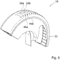
- figure 5 12 shows an isometric view of the brake dust particle filter 16.
- the outwardly directed ribs 50a, 50b and the openings 46a, 46b can be seen.
- the housing 18 can be made in one piece, ie in one piece.
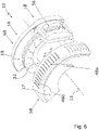
- the housing 18 of the brake dust particle filter 16 can have a first housing part 58 and a second housing part 60 in a second embodiment of the disc brake assembly 10 .
- the first housing part 58 has the first housing side wall 17 .
- the second housing part 60 has the second housing side wall 19 which is axially offset relative to the first housing side wall 17 .
- the first housing side wall 17 along the axis of rotation 13 of the brake disc 12 can be arranged axially offset to the brake disc 12 and the second housing side wall 19 can be arranged on the side of the brake disc 12 facing away from the first housing side wall 17 .
- the first housing part 58 has openings 46a, 46b.
- the second housing part 60, in particular the second housing side wall 19, can be designed in the form of a splash guard, so that in case of doubt a separate splash guard for the brake disc can be dispensed with, which is of particular interest for OE applications.
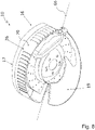
- the first housing part 58 and the second housing part 60 can be connected and/or connected to one another by a pivoting mechanism and/or a folding mechanism in order to be able to quickly open and close the brake dust particle filter 16 again.
- the pivot axis 66 of the pivot mechanism can be arranged parallel to an axis 68 which connects the two housing side walls 17, 19 or runs through them, which in this case also runs parallel to the axis of rotation of the brake disc.
- the peripheral wall 26 of the housing can then be pivoted relative to the two side walls 17, 19 of the housing.
- the pivot axis 66 of the pivot mechanism can extend perpendicularly to the outer peripheral side 70 of the housing peripheral wall 26 of the brake dust particle filter 16 in the assembled state, as shown in FIG 8 is shown. Then the first housing side wall 17 can be pivoted relative to the second housing side wall 19 and the housing peripheral wall 26 .
- the invention relates in summary to a brake dust particle filter 16 for a disc brake arrangement 10 with a brake disc 12 and a brake caliper 14.
- a brake dust particle filter 16 for a disc brake arrangement 10 with a brake disc 12 and a brake caliper 14.
- the housing interior 20 of the housing 18 of the brake dust particle filter 16 at least one tongue 28a to 28e is arranged or formed, with at least one section of this tongue 28a to 28e protruding radially inwards.
- the tongue 28a to 28e is formed through the filter medium 32 of the brake dust particle filter 16 .
- the housing 18 has the shape of a ring segment. It can be used at least for partially accommodating the brake disc 12 in the housing interior 20 .
- a first housing side wall 17 and a second housing side wall 19 and a housing peripheral wall 26, 62, 64 each form parts of the housing 18.
- the housing side walls 17, 19 are spaced axially from one another.
- the housing peripheral wall 26, 62, 64 is arranged radially on the outside in the circumferential direction of the housing 18.
- the housing peripheral wall 26, 62, 64 is arranged or formed between the first housing side wall 17 and the second housing side wall 19.
- the brake dust particle filter 16 is designed to catch particles produced during braking.
Description
Die Erfindung betrifft einen Bremsstaubfilter für eine Scheibenbremsenanordnung mit einer Bremsscheibe und einem Bremssattel. Der Bremstaubpartikelfilter ist zum Auffangen von beim Bremsen entstehenden Partikeln ausgebildet. Die Erfindung betrifft weiterhin eine Schreibenbremsenanordnung mit einem solchen Bremsstaubpartikelfilter.The invention relates to a brake dust filter for a disc brake assembly with a brake disc and a brake caliper. The brake dust particle filter is designed to catch particles produced during braking. The invention further relates to a disk brake arrangement with such a brake dust particle filter.
Es ist bekannt, Partikel, die durch Bremsabrieb entstehen, mit einem Bremsstaubpartikelfilter aufzufangen und zu entsorgen. Derlei Partikel entstehen durch Reibung zwischen Bremsbelag und Bremsscheibe einer Scheibenbremse. Ein solcher Bremsstaubpartikelfilter ist beispielsweise aus
Aus der
Aufgabe der vorliegenden Erfindung ist es demgegenüber, einen Bremsstaubpartikelfilter bereitzustellen, der sowohl effizienter zur Abscheidung von beim Bremsen anfallenden Partikeln ausgebildet ist, als auch zur Nachrüstung bestehender Fahrzeuge geeignet ist. Aufgabe der vorliegenden Erfindung ist es weiterhin, eine Scheibenbremsenanordnung mit einem solchen Bremsstaubpartikelfilter bereitzustellen.In contrast, the object of the present invention is to provide a brake dust particle filter that is designed both more efficiently for separating particles occurring during braking and is also suitable for retrofitting existing vehicles. The object of the present invention is furthermore to provide a disc brake arrangement with such a brake dust particle filter.
Der erfindungsgemäße Bremsstaubpartikelfilter ist für beliebige Anwendungen von Scheibenbremsen geeignet, sowohl mobile als auch stationäre Anwendungen. Bei den mobilen Anwendungen kann dieser beispielsweise in PKW, LKW, Bussen, Schienenfahrzeugen eingesetzt werden. Stationär beispielsweise bei Wellenbremsen, wie sie bei Windkraftanlagen eingesetzt werden.The brake dust particle filter according to the invention is suitable for any application of disc brakes, both mobile and stationary applications. Both mobile applications, this can be used in cars, trucks, buses, rail vehicles, for example. Stationary, for example, with wave brakes, such as those used in wind turbines.
Diese Aufgabe wird durch einen Bremsstaubpartikelfilter gemäß Patentanspruch 1 sowie eine Scheibenbremsenanordnung gemäß Patentanspruch 19 gelöst. Die abhängigen Ansprüche geben bevorzugte Weiterbildungen wieder.This object is achieved by a brake dust particle filter according to patent claim 1 and a disk brake arrangement according to
Der Bremsstaubpartikelfilter weist ein ringsegmentförmiges, etwa bananenförmiges und/oder helmförmiges, Gehäuse auf. In dem Gehäuse wird in einem Montagezustand die Bremsscheibe einer Scheibenbremsenanordnung aufgenommen. Das Gehäuse weist zumindest zwei Gehäuseseitenwände und eine Gehäuseumfangswand auf. Die Gehäuseumfangswand verbindet im montierten Zustand des Bremsstaubpartikelfilters die beiden Gehäuseseitenwände mittelbar oder unmittelbar. Im Innenraum des Gehäuses, d.h. der Bremsscheibe zugewandt, weist der Bremsstaubpartikelfilter ein Filtermedium auf. Um die effektive Filterfläche des Filtermediums zu vergrößern, ist im Bremsstaubpartikelfilter zumindest eine Zunge vorgesehen, die durch das Filtermedium gebildet wird. Hierdurch wird eine höhere Filterwirkung als im Stand der Technik erreicht. Die Zunge erstreckt sich dabei bevorzugt von einem äußeren Umfang zu einem inneren Umfang, d.h. nach radial innen.The brake dust particle filter has a ring segment-shaped, approximately banana-shaped and/or helmet-shaped housing. In the housing, the brake disc of a disc brake assembly is accommodated in an assembled state. The housing has at least two housing side walls and a housing peripheral wall. When the brake dust particle filter is installed, the peripheral wall of the housing connects the two side walls of the housing directly or indirectly. In the interior of the housing, i.e. facing the brake disc, the brake dust particle filter has a filter medium. In order to increase the effective filter surface of the filter medium, at least one tongue, which is formed by the filter medium, is provided in the brake dust particle filter. This achieves a higher filter effect than in the prior art. The tongue preferably extends from an outer circumference to an inner circumference, i.e. radially inwards.
Die Zunge erstreckt sich erfindungsgemäß in einem Gehäuseinnenraum zumindest abschnittsweise mit zumindest einer Radialkomponente von der Gehäuseumfangswand weg. Die Zunge hat erfindungsgemäß eine flache Querschnittsform und weist eine der Gehäuseumfangswand zugewandte Grundfläche, eine in den Gehäuseinnenraum ragende Stirnfläche sowie zumindest eine Seitenfläche auf. Unter flach wird hierin eine Querschnittsform verstanden, deren breite Seite viel größer ist als deren schmale Seite. Alternativ könnte eine solche Querschnittsform auch als platt oder länglich bezeichnet werden. Die in diesem Sinne flache Querschnittsform ergibt des Weiteren aus den Abmessungen des in einem unverarbeiteten Zustand flachen Filtermediums, das eben eine vorbestimmte Dicke aufweist.According to the invention, the tongue extends in a housing interior at least in sections with at least one radial component away from the housing peripheral wall. According to the invention, the tongue has a flat cross-sectional shape and has a base surface facing the peripheral wall of the housing, an end surface protruding into the interior of the housing, and at least one side surface. By flat is meant herein a cross-sectional shape whose wide side is much larger than its narrow side. Alternatively, such a cross-sectional shape could also be referred to as flat or elongated. The flat cross-sectional shape in this sense also results from the dimensions of the filter medium, which is flat in an unprocessed state and has a predetermined thickness.
Die Zunge weist erfindungsgemäß keine von dem Filtermedium separaten stützenden Vorrichtungsbestandteile auf, insbesondere keine die Zunge stützenden Gehäusebestandteile. Das Filtermedium stellt eine ausreichende Steifigkeit bereit, um die Zunge ohne stützende Vorrichtungsbestandteile selbst struktursteif in Form zu halten.According to the invention, the tongue has no supporting device components separate from the filter medium, in particular no housing components supporting the tongue. The filter media provides sufficient rigidity to hold the tongue structurally rigid in shape without any supporting device components.
Die Zunge kann sich von einer Gehäusewand erstrecken, vorzugsweise erstreckt sich die Zunge von der Gehäuseumfangswand. Alternativ oder zusätzlich kann sich die zumindest eine Zunge auch von einer oder beiden der Gehäuseseitenwände erstrecken, so dass diese in etwa in Axialrichtung verläuft. Ferner kann der Bremsstaubpartikelfilter ein Filterelement aufweisen, das das Filtermedium aufweist. Das Filterelement kann eine Filterelement-Stützstruktur aufweisen, auf bzw. an der das Filtermedium befestigt ist und die der Anbringung des Filtermediums im Gehäuse dienen kann. Die Filterelement-Stützstruktur kann beispielsweise aus einem Metallgitter gebildet sein. Beim Vorsehen eines Filterelements ist das Filtermedium besonders leicht und umweltfreundlich austauschbar, da bei einer Beladung des Filtermediums lediglich das Filterelement getauscht werden muss und nicht das komplette Gehäuseteil. Zur Aufnahme des Filterelements ist gemäß dieser Ausführungsform vorteilhaft ein Aufnahmebereich vorgesehen, in den das Filterelement eingesetzt werden kann. In dem Aufnahmebereich kann es beispielsweise durch Clipse oder andere geeignet erscheinende Befestigungselemente gehalten werden. Besonders vorteilhaft weist das Filterelement eine gebogene Form auf, insbesondere eine Kreisbogenform, die mit der Innenform bzw. dem Radius der Gehäuseumfangswand korrespondiert.The tongue can extend from a housing wall, preferably the tongue extends from the housing peripheral wall. Alternatively or additionally, the at least one tongue can also extend from one or both of the housing side walls, so that it runs approximately in the axial direction. Furthermore, the brake dust particle filter can have a filter element that has the filter medium. The filter element may include a filter element support structure to which the filter media is attached and which may be used to mount the filter media in the housing. The filter element support structure can be formed from a metal mesh, for example. When a filter element is provided, the filter medium can be exchanged particularly easily and in an environmentally friendly manner, since when the filter medium is loaded, only the filter element has to be exchanged and not the entire housing part. According to this embodiment, a receiving area is advantageously provided for receiving the filter element, into which the filter element can be inserted. It can be held in the receiving area, for example, by clips or other fastening elements that appear suitable. Particularly advantageously, the filter element has a curved shape, in particular a circular arc shape, which corresponds to the inner shape or the radius of the peripheral wall of the housing.
In einer bevorzugten Ausführungsform kann die Zunge einen im Wesentlichen rechteckförmigen Querschnitt haben, wobei ein Verhältnis einer breiten Seite zu einer schmalen Seite des rechteckförmigen Querschnitts zwischen 15 und 60, bevorzugt zwischen 20 und 40, liegt. Derartige Werte lassen sich für eine Vielzahl von Baugrößen des Bremsstaubpartikelfilters mit den hierin beschriebenen Filtermedientypen erreichen.In a preferred embodiment, the tongue may have a substantially rectangular cross section, with a ratio of a wide side to a narrow side of the rectangular cross section being between 15 and 60, preferably between 20 and 40. Such values can be achieved for a large number of sizes of the brake dust particle filter with the filter media types described here.
Besonders bevorzugt erstreckt sich die zumindest eine Zunge derart in dem Innenraum, dass deren Grundfläche in einem Montagezustand des Bremsstaubpartikelfilters parallel zu einer Drehachse der Bremsscheibe verläuft.The at least one tongue particularly preferably extends in the interior in such a way that its base area runs parallel to an axis of rotation of the brake disc when the brake dust particle filter is in an assembled state.
Gemäß einer weiteren bevorzugten Ausführungsform ist zumindest eine weitere Zunge vorgesehen, die sich in den Gehäuseinnenraum von zumindest einer Gehäuseseitenwand erstreckt. Bevorzugt bilden die sich von der Gehäuseumfangswand erstreckende Zunge und die sich von der Gehäuseseitenwand erstreckende Zunge eine zusammenhängende Zunge, die eine L-förmige oder U-förmige Grundform aufweist. Hierdurch wird die effektive Zungenoberfläche erhöht, was zu einer nochmals verbesserten Abscheideleistung beiträgt. Ferner ist dadurch eine in Radialrichtung Platz sparende Bauweise möglich, da ein Teil der gesamten Zungenoberfläche auf die an der Gehäuseseitenwand vorliegende Zunge verteilt werden kann.According to a further preferred embodiment, at least one further tongue is provided, which extends into the housing interior from at least one housing side wall. Preferably, the tongue extending from the peripheral wall of the housing and the tongue extending from the side wall of the housing form a coherent tongue which has an L-shaped or U-shaped basic shape. This will the effective tongue surface increases, which contributes to an even better separation performance. Furthermore, a design that saves space in the radial direction is thereby possible, since part of the entire tongue surface can be distributed over the tongue present on the side wall of the housing.
Gemäß einer weiteren Ausführungsform kann das Filtermedium eine Faltung aufweisen, die die Zunge bildet, wobei eine Faltenrichtung insbesondere zumindest eine Radialkomponente aufweist. Filtermedien, auch hochtemperaturstabile Filtermedien, lassen sich problemlos maschinell in eine gefaltete Form bringen. Entsprechende Herstellverfahren hierzu sind dem Fachmann bekannt. Dass die Faltenrichtung der Zunge eine Radialkomponente aufweist bedeutet nicht, dass sich diese genau radial erstreckt, sie kann sich jedoch auch genau radial erstrecken. In einer Ausführungsform, bei der sich die Zunge von einer der Gehäuseseitenwände erstreckt, kann die Faltenrichtung (Faltental/Faltenberg) auch axial verlaufen.According to a further embodiment, the filter medium can have a fold that forms the tongue, with a fold direction having in particular at least one radial component. Filter media, including filter media that are stable at high temperatures, can easily be folded by machine. Corresponding production processes for this are known to the person skilled in the art. The fact that the folding direction of the tongue has a radial component does not mean that it extends exactly radially, but it can also extend exactly radially. In an embodiment in which the tongue extends from one of the housing side walls, the fold direction (fold valley/fold peak) can also run axially.
Gemäß einer noch weiteren Ausführungsform kann vorgesehen sein, dass das Filtermedium, das die zumindest eine Zunge bildet, in Form eines formsteifen Formfilterelements vorliegt, das eine gebogene Außenkontur hat, die mit einer Innenkontur der Gehäuseumfangswand des Gehäuses korrespondiert. Gemäß dieser Ausführungsform kann die Zunge nicht als Faltung gebildet sein, sondern in Form eines Vollmaterials. Geeignete poröse Materialien, mit denen sich ein derartiger Körper realisieren lässt, sind beispielsweise gesinterte Metallschäume oder Metallvliese, insbesondere aus Edelstahl.According to yet another embodiment, it can be provided that the filter medium that forms the at least one tongue is in the form of a dimensionally stable form filter element that has a curved outer contour that corresponds to an inner contour of the housing peripheral wall of the housing. According to this embodiment, the tongue cannot be formed as a fold, but in the form of a solid material. Suitable porous materials with which such a body can be realized are, for example, sintered metal foams or metal fleeces, in particular made of stainless steel.
In einer bevorzugten Weiterbildung kann an einer Gehäusewand, insbesondere an der Gehäuseumfangswand, zumindest ein Teil einer Filterelementmontagevorrichtung vorliegen, insbesondere zumindest ein Teil einer Schnellmontagevorrichtung, insbesondere ein Teil einer Clipsverbindung, Schnellmontagelasche und/oder ein magnetisches Verbindungselement. Hierüber können die vorgenannten Filterelemente im Servicefall schnell und einfach getauscht werden. Derartige Filterelementmontagevorrichtungen eignen sich sowohl für die Verwendung mit Filterelementen mit Filterelement-Stützstruktur als auch für Filterelemente, die als Formfilter ausgebildet sind. Alternativ kann das Filtermedium, insbesondere, wenn es ein metallisches Filtermedium aufweist, auch mit dem Gehäuse verschweißt sein.In a preferred development, at least part of a filter element assembly device can be present on a housing wall, in particular on the peripheral wall of the housing, in particular at least part of a quick assembly device, in particular part of a clip connection, quick assembly tab and/or a magnetic connecting element. This allows the aforementioned filter elements to be replaced quickly and easily in the event of service. Such filter element mounting devices are suitable both for use with filter elements with a filter element support structure and for filter elements that are designed as shaped filters. Alternatively, the filter medium can also be welded to the housing, in particular if it has a metallic filter medium.
Darüber hinaus kann das Filterelement zumindest ein mit der Filterelementmontagevorrichtung korrespondierendes Montagegegenelement aufweisen, insbesondere einen zumindest abschnittsweise gebogenen, insbesondere nach radial innen gebogenen, axial verlaufenden Randbereich zumindest eines Umfangsendes, der dazu ausgebildet ist, mit der Schnellmontagevorrichtung in Wirkverbindung zu treten. Bei dem gebogenen Randbereich handelt es sich bevorzugt um einen endständigen Randbereich, der durch die Biegung eine erhöhte Steifigkeit aufweist und so die Befestigungskräfte übertragen kann. An einem dem gebogenen Randbereich abgewandten Ende des Filterelements kann ein alternatives Befestigungselement vorliegen, bspw. an einem separaten Gehäusedeckel, das das Filterelement in dem Innenraum verklemmt.In addition, the filter element can have at least one counter-assembly element that corresponds to the filter element assembly device, in particular an axially extending edge region that is bent at least in sections, in particular bent radially inward, of at least one peripheral end, which is designed to come into operative connection with the quick assembly device. The bent edge area is preferably a terminal edge area which has increased rigidity due to the bend and can thus transmit the fastening forces. At an end of the filter element facing away from the curved edge area, there can be an alternative fastening element, for example on a separate housing cover, which clamps the filter element in the interior.
In weiter bevorzugter Ausgestaltung der Erfindung ist das Filtermedium im Bereich der Zunge in Form einer Sammeltasche bzw. Auffangtasche für Partikel ausgebildet, wobei die Auffangtasche nach unten hin geschlossen ist, so dass Partikel aufgrund der auf sie wirkenden Schwerkraft nicht aus der Auffangtasche fallen können. Der Bremsstaubpartikelfilter kann hierdurch große Partikelmengen zurückhalten. Dem Filtermedium kann die Form der Sammel- bzw. Auffangtasche vorteilhaft bereits bei der Herstellung aufgeprägt werden, so dass die Zunge diese Form struktursteif beibehält. Bevorzugt befindet sich ein tiefster Punkt der Tasche in Montageanordnung in Schwererichtung nach unten weisend.In a further preferred embodiment of the invention, the filter medium in the area of the tongue is designed in the form of a collection pocket or collection pocket for particles, with the collection pocket being closed at the bottom so that particles cannot fall out of the collection pocket due to the force of gravity acting on them. The brake dust particle filter can thus retain large amounts of particles. The shape of the collection or collecting pocket can advantageously already be impressed on the filter medium during production, so that the tongue retains this shape in a structurally rigid manner. A lowest point of the pocket is preferably in the mounted arrangement pointing downwards in the direction of gravity.
Der Bremsstaubpartikelfilter kann zusätzlich zu der zuvor beschriebenen Zunge zumindest eine weitere Zunge im Gehäuseinnenraum aufweisen. Mit anderen Worten weist der Bremsstaubpartikelfilter vorzugsweise eine Mehrzahl von im Gehäuseinnenraum nach innen ragenden Zungen auf, die vorzugsweise in Umfangsrichtung beabstandet angeordnet sind. Die Zungen sind jeweils durch das Filtermedium gebildet. Durch die Anordnung bzw. Ausbildung mehrerer Zungen wird die Filterwirkung weiter signifikant erhöht. Zumindest zwei Zungen können dabei einen jeweils unterschiedlichen Winkel zur Gehäuseumfangswand einnehmen. Unter Winkel zur Gehäuseumfangswand wird hierbei ein Winkel zwischen einer in einem gedachten Kontaktpunkt der Zunge mit der Gehäuseumfangswand angelegten Tangente und der Längserstreckung der Zunge verstanden.In addition to the tongue described above, the brake dust particle filter can have at least one further tongue in the interior of the housing. In other words, the brake dust particle filter preferably has a plurality of tongues which protrude inwards in the housing interior and are preferably arranged at a distance from one another in the circumferential direction. The tongues are each formed by the filter medium. The filter effect is further significantly increased by the arrangement or formation of a plurality of tongues. At least two tongues can each take a different angle to the housing peripheral wall. The angle to the peripheral wall of the housing is understood to be an angle between a tangent applied at an imaginary contact point of the tongue with the peripheral wall of the housing and the longitudinal extension of the tongue.
Der Bremsstaubpartikelfilter ist vorzugsweise so ausgebildet, dass die filternde Wirkung in Umfangsrichtung des Gehäuses zunimmt. Die Zunahme erfolgt dabei bevorzugt von einem Anlagebereich des Gehäuses weg, wobei der Anlagebereich zur Anlage am Bremssattel der Scheibenbremsenanordnung vorgesehen ist. Mit anderen Worten ist der Bremsstaubpartikelfilter vorzugsweise so ausgebildet, dass die Filterwirkung mit zunehmendem Abstand vom Bremssattel bzw. von dem Anlagebereich zur Anlage am Bremssattel, zunimmt. Unter einer besseren Filterwirkung wird hierin beispielsweise die Abscheidbarkeit feinerer Partikelfraktionen verstanden. Dies erfolgt insbesondere durch eine oder mehrere folgender Maßnahmen:
- Die Porosität des Filtermediums nimmt in Umfangsrichtung des Gehäuses ab. Insbesondere weist das Filtermedium an einer Zunge eine größere Porosität auf als das Filtermedium an der nächsten benachbarten Zunge, die sich weiter weg vom Anlagebereich des Bremsstaubpartikelfilters befindet.
- Die Dicke des Filtermediums nimmt in Umfangsrichtung des Gehäuses zu.
- Eine Zunge schließt einen kleineren Winkel mit der Gehäuseumfangswand ein als eine benachbarte Zunge, die sich weiter weg vom Anlagebereich befindet.
- Eine Zunge weist mit ihrem freien Ende weniger weit in den Innenraum des Gehäuses als eine benachbarte Zunge, die sich weiter weg vom Anlagebereich des Bremsstaubpartikelfilters befindet.
- Die Fläche einer Zunge ist kleiner als die Fläche einer benachbarten Zunge, die sich weiter vom Anlagebereich des Bremsstaubpartikelfilters entfernt befindet.
- The porosity of the filter medium decreases in the circumferential direction of the housing. In particular, the filter medium on one tongue has a greater porosity than the filter medium on the next adjacent tongue, which is located further away from the contact area of the brake dust particle filter.
- The thickness of the filter medium increases in the circumferential direction of the housing.
- One tab makes a smaller angle with the housing perimeter wall than an adjacent tab that is further away from the abutment area.
- The free end of one tongue points less far into the interior of the housing than an adjacent tongue, which is located further away from the contact area of the brake dust particle filter.
- The area of one tab is smaller than the area of an adjacent tab that is farther from the contact area of the brake dust particle filter.
Der Bremsstaubpartikelfilter kann zumindest eine Öffnung zum Austritt gefilterter Luft in der Gehäusewand, insbesondere in der Gehäuseumfangswand, aufweisen. Vorzugsweise weist der Bremsstaubpartikelfilter eine Mehrzahl an Öffnungen zum Austritt gefilterter Luft in der Gehäusewand, insbesondere in der Gehäuseumfangswand, auf.The brake dust particle filter can have at least one opening for filtered air to exit in the housing wall, in particular in the peripheral wall of the housing. The brake dust particle filter preferably has a plurality of openings in the housing wall, in particular in the peripheral wall of the housing, for the outlet of filtered air.
Zumindest eine Öffnung ist vorzugsweise in einem Gehäuseendbereich vorgesehen, der - in Umfangsrichtung des Gehäuses betrachtet - im Bereich des Bremssattels ausgebildet ist. Der Gehäuseendbereich übergreift vorzugsweise zumindest einen nach radial außen offenen Bereich des Bremssattels, da dort typischerweise ein hoher Bremsstaubaustritt erfolgt, der neben dem Bremsenabrieb, der den Bremssattel in Tangentialrichtung verlässt, die größte Emissionsquelle darstellt. Bevorzugt handelt es sich bei dem Filtermedium um einen zusammenhängenden Materialstreifen, der sich sowohl über die Mehrzahl der innenliegenden Zungen als auch über die Innenseite der Gehäuseumfangswand im Gehäuseendbereich erstreckt.At least one opening is preferably provided in a housing end area which—viewed in the circumferential direction of the housing—is formed in the area of the brake caliper. The housing end area preferably overlaps at least one area of the brake caliper that is open radially outwards, since a high level of brake dust typically escapes there, which represents the largest emission source alongside the brake dust that leaves the brake caliper in the tangential direction. The filter medium is preferably a coherent strip of material that extends both over the majority of the internal tongues and over the inside of the housing peripheral wall in the housing end area.
Um zu verhindern, dass Luft durch den Staudruck bei der Fahrt entgegen der Filtrationsrichtung durch das Filtermedium gepresst wird, kann an der Gehäusewand, insbesondere an der Gehäuseumfangswand, zumindest eine sich nach außen erstreckende Rippe angeordnet oder ausgebildet sein. Vorzugsweise sind eine Mehrzahl von nach außen ragenden Rippen an der Gehäusewand, insbesondere der Gehäuseumfangswand, vorgesehen. Die zumindest eine nach außen ragende Rippe kann bevorzugt im Bereich der zumindest einen Öffnung vorgesehen sein, so dass die Rippe die jeweilige Öffnung in Fahrtrichtung zumindest teilweise verdeckt, so dass ein durch die Fahrt erzeugter dynamischer Druck nicht auf die Öffnung einwirkt.Vorzugsweise sind mehrere nach außen ragende Rippen jeweils im Bereich einer Öffnung zum Austritt gefilterter Luft vorgesehen, bevorzugt ist jede der Öffnungen mit einer vorbeschriebenen Rippe versehen.In order to prevent air from being forced through the filter medium counter to the filtration direction by the dynamic pressure when driving, on the housing wall, in particular at least one outwardly extending rib may be arranged or formed on the housing peripheral wall. A plurality of outwardly projecting ribs are preferably provided on the housing wall, in particular the housing peripheral wall. The at least one outwardly protruding rib can preferably be provided in the area of the at least one opening, so that the rib at least partially covers the respective opening in the direction of travel, so that dynamic pressure generated by driving does not act on the opening externally protruding ribs are each provided in the area of an opening for the outlet of filtered air, preferably each of the openings is provided with a rib as described above.
Das Filtermedium ist vorzugsweise derart ausgebildet, dass es auch bei einer Temperatur von mehr als 600°C stabil ist, um den Temperaturen in unmittelbarer Umgebung einer Scheibenbremse widerstehen zu können. Das Filtermedium kann dabei ein Metall, ein Metallfaservlies, Glas, Keramik und/oder einen hochtemperaturbeständigen Kunststoff, insbesondere Polyetheretherketon, aufweisen. Bevorzugt handelt es sich bei dem Filtermedium um ein gesintertes Metallvlies, das sich zur Ausbildung eines formstabilen Filterelements mit integralen Zungen eignet.The filter medium is preferably designed in such a way that it is also stable at a temperature of more than 600° C. in order to be able to withstand the temperatures in the immediate vicinity of a disc brake. The filter medium can have a metal, a metal fiber fleece, glass, ceramic and/or a high-temperature-resistant plastic, in particular polyetheretherketone. The filter medium is preferably a sintered metal fleece that is suitable for forming a dimensionally stable filter element with integral tongues.
Jedoch auch das Gehäuse soll vorteilhaft über eine hinreichende Temperaturbeständigkeit verfügen; zu diesem Zweck kann es aus einem Metallblech, bevorzugt Stahlblech, ausgebildet sein. Neben der hervorragenden Temperaturbeständigkeit bietet Stahlblech den weiteren Vorteil, dass das Gehäuse durch einen einfachen Umformprozess erhalten werden kann, beispielsweise durch Tiefziehen.However, the housing should also advantageously have sufficient temperature resistance; for this purpose it can be formed from sheet metal, preferably sheet steel. In addition to the excellent temperature resistance, sheet steel offers the further advantage that the housing can be obtained by a simple forming process, for example by deep drawing.
Das ringsegmentförmige Gehäuse deckt vorzugsweise einen großen Winkelbereich der Bremsscheibe ab, um eine hohe Filtrationswirkung zu erzielen. Das Gehäuse erstreckt sich dabei vorzugsweise über einen Ringsegmentwinkel von mehr als 45°, insbesondere von mehr als 75°, besonders bevorzugt von mehr als 90°. Es ist bei der Wahl eines geeigneten Umgriffswinkels ein Zielkonflikt zwischen dem Anteil abzufiltrierender Partikel sowie der der Scheibenbremse zur Verfügung stellbaren Kühlleistung zu lösen.The housing in the form of a ring segment preferably covers a large angular range of the brake disc in order to achieve a high filtration effect. The housing preferably extends over a ring segment angle of more than 45°, in particular more than 75°, particularly preferably more than 90°. When choosing a suitable wrap angle, a conflict of objectives between the proportion of particles to be filtered and the cooling capacity that can be made available to the disc brake must be resolved.
Zur Erleichterung der Montage des Gehäuses kann das Gehäuse ein erstes und ein zweites Gehäuseteil aufweisen. Die beiden Gehäuseteile sind dabei vorzugsweise zumindest teilweise axial beidseitig der Bremsscheibe anordenbar. Besonders bevorzugt sind das erste Gehäuseteil und das zweite Gehäuseteil reversibel lösbar verbindbar.To facilitate assembly of the housing, the housing can have a first and a second housing part. The two housing parts can preferably be arranged at least partially axially on both sides of the brake disc. Particularly preferably, the first housing part and the second housing part can be reversibly and detachably connected.
Alternativ können die beiden Gehäuseteile auch unlösbar verbunden sein, beispielsweise verschweißt. Vorteilhaft wird gemäß dieser Ausführungsform das Filtermedium bereits vor dem Verbinden der Gehäuseteile eingelegt, so dass zumindest der Vormontageprozess vereinfacht ist, wenn auch nicht der Austausch des Filtermediums im Service. Es ist in diesem Fall jedoch denkbar, im Servicefall den gesamten Bremsstaubfilter (inkl. Gehäuse und Filtermedium) auszutauschen, um diesen beispielsweise einer Aufarbeitung zuzuführen. Alternativ zu einer Verschweißung kann vorgesehen sein, dass das erste Gehäuseteil und das zweite Gehäuseteil miteinander über eine Bördelverbindung verbunden sind.Alternatively, the two housing parts can also be non-detachably connected, for example welded. According to this embodiment, the filter medium is advantageously already inserted before the housing parts are connected, so that at least the pre-assembly process is simplified, even if the replacement of the filter medium during service is not. In this case, however, it is conceivable to replace the entire brake dust filter (including the housing and filter medium) in the event of a service, in order to send it to a refurbishment, for example. As an alternative to welding, it can be provided that the first housing part and the second housing part are connected to one another via a flanged connection.
Zur Verbindung der beiden Gehäuseteile kann eine Schraubverbindung, Clipverbindung, ein Klappmechanismus und/oder ein Schwenkmechanismus vorgesehen sein.A screw connection, clip connection, a folding mechanism and/or a pivoting mechanism can be provided to connect the two housing parts.
Die Gehäuseumfangswand kann Teil des ersten Gehäuseteils oder des zweiten Gehäuseteils sein, so dass diese mit einer der beiden Gehäuseseitenwände verbunden ist. Die Gehäuseumfangswand kann ferner zumindest teilweise aus sich überlappenden Gehäuseteilen ausgebildet sein.The peripheral wall of the housing can be part of the first housing part or the second housing part, so that it is connected to one of the two side walls of the housing. The housing peripheral wall can also be formed at least partially from overlapping housing parts.
Ein Gehäuseteil kann relativ zu einem ortsfest verbleibenden weiteren Gehäuseteil verschwenkbar sein. Die Schwenkachse eines solchen Schwenkmechanismus kann sich parallel zu einer die beiden Gehäuseseitenwände verbindenden Achse, insbesondere parallel zur Rotationsachse der Bremsscheibe, erstrecken. In diesem Fall ist besonders bevorzugt das Gehäuseteil, das die Gehäuseumfangswand aufweist, zumindest teilweise relativ zu dem weiteren Gehäuse verschwenkbar. Alternativ oder zusätzlich dazu kann die Schwenkachse in radialer Richtung des Gehäuses bzw. in Bezug zur Bremsscheibe verlaufen, d.h. normal zur Rotationsachse der Bremsscheibe. In diesem Fall ist vorzugsweise eine erste Gehäuseseitenwand relativ zu dem weiteren Gehäuse verschwenkbar.A housing part can be pivotable relative to another housing part that remains stationary. The pivot axis of such a pivot mechanism can extend parallel to an axis connecting the two housing side walls, in particular parallel to the axis of rotation of the brake disc. In this case, the housing part, which has the housing peripheral wall, is particularly preferably pivotable at least partially relative to the further housing. Alternatively or additionally, the pivot axis can run in the radial direction of the housing or in relation to the brake disc, i.e. normal to the axis of rotation of the brake disc. In this case, a first housing side wall can preferably be pivoted relative to the further housing.
Die vorbeschriebene Verschwenkbarkeit vereinfacht einen Austausch des Filtermediums im Servicefall deutlich.The above-described pivotability significantly simplifies replacement of the filter medium in the event of service.
Die erfindungsgemäße Aufgabe wird weiterhin gelöst durch eine Scheibenbremsenanordnung mit einer Bremsscheibe, einem Bremssattel und einem zuvor beschriebenen Bremsstaubpartikelfilter.The object according to the invention is also achieved by a disc brake arrangement with a brake disc, a brake caliper and a brake dust particle filter as described above.
Der Bremsstaubpartikelfilter kann eine ortsfeste Position relativ zu dem Bremssattel, einem Radlagergehäuse und/oder einem Spritzschutz aufweisen. Alternativ oder zusätzlich dazu kann der Bremsstaubpartikelfilter am Bremssattel, an einem Radlagergehäuse und/oder an einem Spritzschutz befestigt sein, wobei eine Befestigung am Bremssattel vorteilhaft vorgesehen werden kann, wenn es sich um einen sog. Festsattel handelt. Besonders vorteilhaft kann der Bremsstaubpartikelfilter an den selben Befestigungspunkten mit dem Radlagergehäuse verbunden werden, wie auch der Bremssattel. Ferner können die Schrauben, mit denen der Bremssattel mit dem Radlagergehäuse verschraubt ist, zumindest im Bereich eines Schraubenkopfs ein Sacklochgewinde aufweisen, so dass der Bremsstaubpartikelfilter mit den Schrauben verbindbar ist, so dass vorteilhaft nicht die sicherheitskritische Verschraubung des Bremssattel(halters) mit dem Radlagergehäuse beeinflusst wird (Setzen/Vorspannkraftänderung).The brake dust particle filter can have a stationary position relative to the brake caliper, have a wheel bearing housing and/or a splash guard. Alternatively or additionally, the brake dust particle filter can be attached to the brake caliper, to a wheel bearing housing and/or to a splash guard, with attachment to the brake caliper advantageously being provided if it is a so-called fixed caliper. The brake dust particle filter can be connected to the wheel bearing housing at the same attachment points as the brake caliper. Furthermore, the screws with which the brake caliper is screwed to the wheel bearing housing can have a blind hole thread at least in the area of a screw head, so that the brake dust particle filter can be connected to the screws, so that advantageously the safety-critical screw connection of the brake caliper (holder) to the wheel bearing housing is not affected (setting/change in preload force).
In besonders bevorzugter Ausgestaltung der Erfindung kann es sich bei einem Gehäuseteil des Bremsstaubpartikelfilters um ein die Bremsscheibe innenliegend zumindest teilweise bedeckendes Spritzschutzelement, insbesondere Spritzschutzblech, handeln. Hierdurch kann auf ein zusätzliches Spritzschutzblech verzichtet werden, so dass Gewicht eingespart werden kann, was aufgrund einer Anordnung im ungefederten Bereich eines Fahrwerks fahrdynamische Vorteile bietet.In a particularly preferred embodiment of the invention, a housing part of the brake dust particle filter can be a splash protection element, in particular a splash protection plate, that at least partially covers the inside of the brake disk. As a result, an additional splash guard can be dispensed with, so that weight can be saved, which offers advantages in terms of driving dynamics due to an arrangement in the unsprung area of a chassis.
Um eine besonders effektive Partikelabscheidung zu bewirken, ist der Bremsstaubpartikelfilter vorzugsweise unmittelbar an den Bremssattel anschließend angeordnet. Der Bremsstaubpartikelfilter ist dabei vorzugsweise dem Bremssattel nachgelagert angeordnet, wobei sich der Begriff "nachgelagert" auf die Rotationsrichtung der Bremsscheibe bei einer bestimmungsgemäßen Vorwärtsfahrt des Fahrzeuges bezieht, an dem die Scheibenbremsenanordnung vorgesehen ist.In order to bring about a particularly effective particle separation, the brake dust particle filter is preferably arranged immediately adjacent to the brake caliper. The brake dust particle filter is preferably arranged downstream of the brake caliper, the term “downstream” referring to the direction of rotation of the brake disc when the vehicle on which the disc brake arrangement is provided is driving forward as intended.
Der Bremsstaubpartikelfilter bedeckt vorzugsweise zumindest teilweise eine Außenseite des Bremssattels, besonders bevorzugt eine Umfangs-Außenseite bzw. radiale Außenseite des Bremssattels. Die Überdeckung des Bremssattels erfolgt dabei vorzugsweise mit dem Gehäuseendbereich. Besonders bevorzugt ist der Bremssattel im Bereich der Umfangs-Außenseite, an der meist Öffnungen zur Kühlluftzufuhr und/oder Service (Entnahme der Reibbeläge) vorliegen, vollständig, zumindest jedoch im Bereich der Öffnungen, von dem Gehäuseendbereich des Bremsstaubpartikelfilters überdeckt, so dass keine ungefilterte Abströmung in diesem Bereich auftritt, sondern von dort austretende, partikelbeladene Luft zunächst durch das Filtermedium und schließlich durch die Öffnung in der Gehäuseumfangswand in die Umgebung strömt.The brake dust particle filter preferably at least partially covers an outside of the brake caliper, particularly preferably a peripheral outside or radial outside of the brake caliper. The brake caliper preferably overlaps with the housing end area. The brake caliper is particularly preferably completely covered by the housing end area of the brake dust particle filter in the area of the outer peripheral side, where there are usually openings for cooling air supply and/or service (removal of the friction linings), at least in the area of the openings, so that there is no unfiltered outflow occurs in this area, but particle-laden air escaping from there, first through the filter medium and finally through the opening flows into the environment in the peripheral wall of the housing.
In weiter bevorzugter Ausgestaltung der Scheibenbremsenanordnung ist die zumindest eine nach innen ragende Zunge mit ihrem freien Ende zum Bremssattel hin ausgerichtet. Vorzugsweise sind mehrere, insbesondere alle, Zungen mit ihren jeweils freien Enden zum Bremssattel hin ausgerichtet. Hierdurch kann die Filtereffektivität weiter erhöht werden, da Bremsstaubpartikel, die von der Rotation tangential mitgenommen werden, quasi durch die Form der Zungen aufgefangen werden können.In a further preferred embodiment of the disc brake arrangement, the free end of the at least one inwardly projecting tongue is aligned towards the brake caliper. Preferably, several, in particular all, tongues are aligned with their respective free ends towards the brake caliper. As a result, the filter effectiveness can be further increased, since brake dust particles that are carried along tangentially by the rotation can be caught by the shape of the tongues.
Weitere Merkmale und Vorteile der Erfindung ergeben sich aus der nachfolgenden Beschreibung mehrerer Ausführungsbeispiele der Erfindung, aus den Patentansprüchen sowie den Figuren, die erfindungswesentliche Einzelheiten zeigen. Die in den Figuren gezeigten Merkmale sind derart dargestellt, dass die erfindungsgemäßen Besonderheiten deutlich sichtbar gemacht werden können. Die verschiedenen Merkmale können je einzeln für sich oder zu mehreren in beliebigen Kombinationen bei Varianten der Erfindung verwirklicht sein und sind demgemäß miteinander kombinierbar.Further features and advantages of the invention result from the following description of several exemplary embodiments of the invention, from the patent claims and the figures, which show details essential to the invention. The features shown in the figures are presented in such a way that the special features according to the invention can be made clearly visible. The various features can each be implemented individually or collectively in any combination in variants of the invention and can accordingly be combined with one another.
In der Zeichnung zeigen:
- Fig. 1
- eine Seitenansicht auf eine erfindungsgemäße Scheibenbremsenanordnung mit einer ersten Ausführungsform des Bremsstaubpartikelfilters;
- Fig. 2
- eine isometrische Ansicht eines Bremsstaubpartikelfilters gemäß einer weiteren Ausführungsform;
- Fig. 3
- eine Querschnittsansicht des Bremsstaubpartikelfilters gemäß
Fig. 2 . - Fig. 4
- eine isometrische Ansicht eines Bremsstaubpartikelfilters gemäß einer noch weiteren Ausführungsform;
- Fig. 5
- eine isometrische Ansicht des Bremsstaubpartikelfilters gemäß
Fig. 1 ; - Fig. 6
- eine isometrische Ansicht eines ersten Gehäuseteils und eines zweiten Gehäuseteils des Gehäuses eines Bremsstaubpartikelfilters in einer zweiten Ausführungsform der Scheibenbremsenanordnung;
- Fig. 7
- eine isometrische Ansicht auf die Verbindung eines ersten Gehäuseteils und eines zweiten Gehäuseteils einer vierten Ausführungsform der Scheibenbremsenanordnung durch einen Schwenkmechanismus und/oder einen Klappmechanismus; und
- Fig. 8
- eine isometrische Ansicht auf die Verbindung des ersten Gehäuseteils und des zweiten Gehäuseteils durch einen Schwenkmechanismus und/oder einen Klappmechanismus entlang einer weiteren Schwenkachse in einer fünften Ausführungsform der Scheibenbremsenanordnung.
- 1
- a side view of a disc brake assembly according to the invention with a first embodiment of the brake dust particle filter;
- 2
- an isometric view of a brake dust particle filter according to another embodiment;
- 3
- a cross-sectional view of the brake dust particle filter according to FIG
2 . - 4
- 14 is an isometric view of a brake dust particle filter according to yet another embodiment;
- figure 5
- an isometric view of the brake dust particle filter according to FIG
1 ; - 6
- an isometric view of a first housing part and a second housing part of the housing of a brake dust particle filter in a second embodiment of the disc brake assembly;
- 7
- an isometric view of the connection of a first housing part and a second housing part of a fourth embodiment of the disc brake assembly by a pivoting mechanism and/or a folding mechanism; and
- 8
- an isometric view of the connection of the first housing part and the second housing part by a pivot mechanism and/or a folding mechanism along a further pivot axis in a fifth embodiment of the disc brake assembly.
Der Bremstaubpartikelfilter 16 weist eine erste Gehäuseseitenwand 17 auf, welche einen Teil eines ringsegmentförmigen Gehäuses 18 bildet. Zur ersten Gehäuseseitenwand 17 befindet sich entlang der Drehachse 13 der Bremsscheibe 12 axial beabstandet eine zweite Gehäuseseitenwand 19 (siehe
Der Bremsstaubpartikelfilter 16 kann insbesondere in Rotationsrichtung R der Bremsscheibe 12 bei Vorwärtsfahrt eines Fahrzeugs, an dem die Scheibenbremsenanordnung 10 angeordnet werden kann, dem Bremssattel 14 nachgelagert angeordnet sein.The brake
In
Das Gehäuse 18 weist eine sich radial außen in Umfangsrichtung des Bremsstaubpartikelfilters 16 erstreckende Gehäuseumfangswand 26 auf. Die Gehäuseseitenwände 17 (siehe
Der Bremsstaubpartikelfilter 16 weist ferner Zungen 28a, 28b, 28c, 28d, 28e auf. Diese Zungen 28a bis 28e erstrecken sich von der Gehäuseumfangswand 26 des Bremsstaubpartikelfilters 16 und sind aus dem Filtermedium 32 gebildet, was in der Abbildung der
Das Filtermedium 32 bildet die Zungen 28a bis 28e jeweils durch eine U-förmige bzw. V-förmige Faltung 42a, 42b, 42c, 42d, 42e aus, die sich mit zumindest einer Radialkomponente nach innen erstreckt.The
Bei dem Filtermedium handelt es sich um einen zusammenhängenden Materialstreifen, der sowohl alle Zungen 28a bis 28e bildet als sich auch über die Innenseite der Gehäuseumfangswand 26 in den Gehäuseendbereich 52 erstreckt.The filter medium is a coherent strip of material that forms all of the
Die der Gehäuseumfangswand 34 zugewandte Seite ist hier beispielhaft an der Zunge 28a mit 34 und die abgewandte Seite mit 36 bezeichnet. Die effektive Filterfläche ist somit in Umfangsrichtung des Gehäuseinnenraums 20 durch die Zungen 28a bis 28e vergrößert. Das Filtermedium 32 ist ferner an Abschnitten 38a, 38b, 38c, 38d der Gehäuseumfangswand 26 zwischen den Zungen 28a bis 28e angeordnet. Hierdurch ist das Filtermedium 32 unmittelbar mit der Gehäuseumfangswand 26 verbunden. Insbesondere ist es an der Gehäuseumfangswand 26 befestigt. Alternativ dazu kann es auch über weitere Zwischenschichten mittelbar mit der Wand des Gehäuses 18 verbunden sein, insbesondere mittels einer Filterelement-Stützstruktur, etwa aus einem Metallgitter.The side facing the
Das Filtermedium 32 mit den durch dieses integral ausgebildeten Zungen 28a bis 28e liegt gemäß dieser Ausführungsform als gefalteter Medienabschnitt vor, der die Faltungen 42a bis 42e aufweist, wobei der gefaltete Medienabschnitt eine ausreichende Eigensteifigkeit aufweist, um als Filterelement 300 gehandhabt zu werden und zu Servicezwecken aus dem Gehäuse 18 des Bremsstaubpartikelfilters 16 entnommen /eingesetzt zu werden. An einem seiner in Umfangsrichtung gesehen axial verlaufenden Endkanten weist das Filterelement 300 einen radial nach innen gebogenen Randbereich 420 auf, der dazu ausgebildet ist, mit einer Filterelementmontagevorrichtung, die auf Seite des Gehäuses vorliegt, in Wirkverbindung zu treten. So kann das Filterelement 300 mit dem gebogenen Randbereich 420 beispielsweise hinter einer Befestigungslasche formschlüssig verklemmt werden.According to this embodiment, the
Bei einer weiteren Ausführungsform weist der Bremsstaubpartikelfilter zusätzlich zu dem Filtermedium 32 ein weiteres Filtermedium auf (nicht gezeigt). Hierbei ist das Filtermedium 32 zwischen der jeweiligen Zunge 28a bis 28e und dem weiteren Filtermedium angeordnet. Das weitere Filtermedium weist eine größere Porosität auf als das erste Filtermedium. Bei einer alternativen Ausführungsform kann der Bremsstaubpartikelfilter 16 zusätzliche Filtermedien mit unterschiedlicher Porosität aufweisen.In a further embodiment, the brake dust particle filter has a further filter medium (not shown) in addition to the
Der Bremsstaubpartikelfilter 16 kann derart ausgebildet sein, dass die Filterwirkung auf die durch die Bremsscheibe 12 in Umfangsrichtung bewegte Luft zunimmt. Hierzu kann die Porosität des Filtermediums 32 in Umfangsrichtung des Gehäuses, beginnend in einem zur Anlage am Bremssattel 14 (siehe
Der Bremsstaubpartikelfilter 16 weist in seiner Gehäuseumfangswand 26 Öffnungen 46a bis 46e auf (siehe
Gemäß der in
Wie in
Wie in
Alternativ oder zusätzlich dazu kann sich in einer vierten Ausführungsform der Scheibenbremsenanordnung 10 die Schwenkachse 66 des Schwenkmechanismus senkrecht zur Außenumfangsseite 70 der Gehäuseumfangswand 26 des Bremsstaubpartikelfilters 16 im montierten Zustand erstrecken, wie in
Unter Vornahme einer Zusammenschau aller Figuren der Zeichnung betrifft die Erfindung zusammenfassend einen Bremsstaubpartikelfilter 16 für eine Scheibenbremsenanordnung 10 mit einer Bremsscheibe 12 und einem Bremssattel 14. Im Gehäuseinnenraum 20 des Gehäuses 18 des Bremsstaubpartikelfilters 16 ist zumindest eine Zunge 28a bis 28e angeordnet oder ausgebildet, wobei zumindest ein Abschnitt dieser Zunge 28a bis 28e radial nach innen ragt. Die Zunge 28a bis 28e ist durch das Filtermedium 32 des Bremsstaubpartikelfilters 16 ausgebildet. Das Gehäuse 18 weist die Form eines Ringsegments auf. Es kann zumindest zur teilweisen Aufnahme der Bremsscheibe 12 im Gehäuseinnenraum 20 verwendet werden. Eine erste Gehäuseseitenwand 17 und eine zweite Gehäuseseitenwand 19 sowie eine Gehäuseumfangswand 26, 62, 64 bilden jeweils Teile des Gehäuses 18. Die Gehäuseseitenwände 17, 19 sind axial voneinander beabstandet. Die Gehäuseumfangswand 26, 62, 64 ist radial außen in Umfangsrichtung des Gehäuses 18 angeordnet. Die Gehäuseumfangswand 26, 62, 64 ist zwischen der ersten Gehäuseseitenwand 17 und der zweiten Gehäuseseitenwand 19 angeordnet oder ausgebildet. Der Bremsstaubpartikelfilter 16 ist zum Auffangen von beim Bremsen entstehenden Partikeln ausgebildet.Taking all the figures of the drawing together, the invention relates in summary to a brake
Claims (15)
- Brake dust particle filter (16) for a disk brake arrangement (10) having a brake disk (12) and a brake caliper (14), wherein the brake dust particle filter (16) is configured to capture particles generated during braking, and wherein the brake dust particle filter (16) comprises the following:- A ring segment-shaped housing (18) for at least partially receiving the brake disk (12) in a housing interior space (20), wherein the housing (18) features two housing side walls (17, 19) axially spaced apart from each other and a housing peripheral wall (26, 62, 64) extending radially outwardly in circumferential direction, and wherein the housing peripheral wall (26, 62, 64) is disposed or formed between the housing side walls (17, 19);- at least one tongue (28a, 28b, 28c, 28d, 28e) projecting inwardly in the housing interior space (20) from the housing peripheral wall (26, 62, 64) at least in sections with at least one radial component;characterized in that- the tongue (28a, 28b, 28c, 28d) features a flat cross-sectional shape and at least one base surface facing the housing peripheral wall (26, 62, 64), a front face projecting into the housing interior space (20), and at least one side face, and- at least one filter media (32);wherein the tongue (28a, 28b, 28c, 28d, 28e) is formed by the filter media (32) and wherein the tongue (28a, 28b, 28c, 28d) does not feature any supporting apparatus components, in particular housing components, separate from the filter media (32) and the filter media (32) provides a sufficient rigidity to keep the tongue (28a, 28b, 28c, 28d) structurally rigid in shape.
- Brake dust particle filter according to claim 1,
wherein the tongue (28a, 28b, 28c, 28d) has a substantially rectangular cross-section, wherein a proportion of a wide side with respect to a narrow side of the rectangular cross-section is between 15 and 60, preferably between 20 and 40. - Brake dust particle filter according to claim 1 or 2,- in which the tongue (28a, 28b, 28c, 28d, 28e) extends from a housing wall (17, 19, 26, 62, 64), in particular along the housing peripheral wall (26, 62, 64) and/or- which features a filter element (300) with the filter media (32), wherein the filter element (300) preferably features a filter element support structure on which the filter media (32) is attached and the filter element is disposed, in particular reversibly replaceably, in the housing (18).
- Brake dust particle filter according to one of the claims 1 to 3, wherein at least one further tongue is provided which extends into the housing interior space (20) from at least one housing side wall (17, 19), wherein preferably the tongue (28a, 28b, 28c, 28d) extending from the housing peripheral wall (26, 62, 64) and the tongue extending from the housing side wall form a continuous tongue which has an L-shaped or U-shaped basic form.
- Brake dust particle filter according to one of the claims 1 to 4, in which the filter media (32) features a folding (42a, 42b, 42c, 42d, 42e) forming the tongue (28a, 28b, 28c, 28d, 28e), wherein a folding direction features in particular at least one radial component.
- Brake dust particle filter according to one of the claims 1 to 5, in which the filter media (32), which forms the at least one tongue (28a, 28b, 28c, 28d, 28e), is provided as a dimensionally stable shaped filter element (300) having a curved outer contour, which corresponds with an inner contour of the housing peripheral wall (26, 62, 64) of the housing (18).
- Brake dust particle filter according to claim 6, wherein at least one part of a filter element mounting device, in particular at least one part of a quick mounting device, in particular one part of a clip connection, quick mounting tongue and/or a magnetic connecting element, is provided on a housing wall (17, 19, 26, 62, 64), in particular on the housing peripheral wall (26, 62, 64).
- Brake dust particle filter according to claim 6 and 7, wherein the filter element (300) features at least one mounting counter element corresponding with the filter element mounting device, in particular an at least sectionwise curved, in particular radially inwardly curved, axially extending peripheral area (420) designed to establish an operative connection with a filter element mounting device.
- Brake dust particle filter according to one of the preceding claims, in which the filter media (32) is designed in the area of the tongue (28a, 28b, 28c, 28d, 28e) in the shape of a collecting pocket for particles, wherein the collecting pocket is closed at the bottom in the assembled state of the brake dust particle filter in order to prevent the particles from escaping due to the force of gravity acting on the particles.
- Brake dust particle filter according to one of the preceding claims, characterized in that the brake dust particle filter (16) features a plurality of tongues (28a, 28b, 28c, 28d, 28e) projecting inwardly in the housing interior space (20) and which are disposed spaced apart in the circumferential direction, wherein the tongues (28a, 28b, 28c, 28d, 28e) are each formed by the filter media (32), wherein preferably at least two tongues (28a, 28b, 28c, 28d, 28e) enclose a different angle (β1, β2, β3, β4, β5) with the housing peripheral wall (26, 62, 64).
- Brake dust particle filter according to one of the preceding claims, in which the brake dust particle filter (16) is designed in such a way that the filtering effect on the air flowing through the brake disk (12) in the circumferential direction of the housing (18) increases, in particular as- the porosity of the filter media (32) decreases in the circumferential direction of the housing (18), beginning in an abutment area (44) of the brake dust particle filter (16) intended for abutment against the brake caliper (14); in particular in combination with claim 7, the filter media (32) features at a tongue (28a, 28b, 28c, 28d, 28e) a greater porosity than the filter media (32) at the next adjacent tongue (28a, 28b, 28c, 28d, 28e) which is located further away from an abutment area (44) of the brake dust particle filter (16) intended for abutment against the brake caliper (14);- the thickness of the filter media (32) increases in the circumferential direction of the housing (18), starting in an abutment area (44) of the brake dust particle filter (16) intended for abutment against the brake caliper (14);- in combination with claim 7, at least one tongue (28a, 28b, 28c, 28d, 28e) encloses a smaller angle (β1, β2, β3, β4, β5) with the housing peripheral wall (26) to an abutment area (44) intended for abutment against the brake caliper (14) than an adjacent tongue (28a, 28b, 28c, 28d, 28e) which is located further away from the abutment area (44) of the brake dust particle filter (16) intended for abutment against the brake caliper (14);- in combination with claim 10, the free end (30a, 30b, 30c, 30d, 30e) of at least one tongue (28a, 28b, 28c, 28d, 28e) projects radially inwardly into the interior space of the housing less than an adjacent tongue (28a, 28b, 28c, 28d, 28e) located in particular further away from an abutment area (44) of the brake dust particulate filter (16) intended for abutment against the brake caliper (14); and/or- in combination with claim 10, the area of at least one tongue (28a, 28b, 28c, 28d, 28e) projecting into the housing interior space (20) is smaller than the area of an adjacent tongue (28a, 28b, 28c, 28d, 28e) projecting into the housing interior space (20), which tongue is located in particular further away from an abutment area (44) of the brake dust particle filter (16) intended for abutment against the brake caliper (14).
- Brake dust particle filter according to one of the preceding claims, in which the brake dust particle filter (16) features at least one opening (46a - 46e) for the exit of filtered air in the housing wall (17, 19, 26), in particular in the housing peripheral wall (26, 62, 64), wherein the brake dust particle filter (16) preferably features a plurality of openings (46a - 46e) for the exit of filtered air in the housing wall (17, 19, 26), in particular in the housing peripheral wall (26, 62, 64).
- Brake dust particle filter according to claim 12, in which the brake dust particle filter (16) features a housing end area (52) as seen in the circumferential direction of the housing (18) for at least partially covering the brake caliper (14) on an outer periphery, wherein at least one opening (46a - 46e) is provided in the housing end area (52) for the exit of filtered air, in particular a plurality of openings (46a - 46e) for the exit of filtered air.
- Brake dust particle filter according to one of the preceding claims, in which at least one outwardly projecting rib (50a, 50b) is disposed or formed on the housing wall (17, 19, 26), in particular on the housing peripheral wall (26), preferably a plurality of outwardly projecting ribs (50a, 50b) are disposed or formed on the housing wall (17, 19, 26), in particular on the housing peripheral wall (26), wherein the rib (50a, 50b) or the ribs (50a, 50b) are preferably each disposed adjacent to an opening and at least partially cover it with respect to a predetermined inflow direction.
- Disk brake arrangement (10), with a brake disk (12), a brake caliper (14), and a brake dust particle filter (16) according to one of the claims 1 to 14.
Applications Claiming Priority (2)
| Application Number | Priority Date | Filing Date | Title |
|---|---|---|---|
| DE102018112261 | 2018-05-22 | ||
| PCT/EP2019/055790 WO2019223914A1 (en) | 2018-05-22 | 2019-03-07 | Brake dust particle filter and disc brake assembly comprising a brake dust particle filter |
Publications (2)
| Publication Number | Publication Date |
|---|---|
| EP3797229A1 EP3797229A1 (en) | 2021-03-31 |
| EP3797229B1 true EP3797229B1 (en) | 2022-10-19 |
Family
ID=65812272
Family Applications (1)
| Application Number | Title | Priority Date | Filing Date |
|---|---|---|---|
| EP19711524.9A Active EP3797229B1 (en) | 2018-05-22 | 2019-03-07 | Brake dust particle filter and disc brake assembly comprising a brake dust particle filter |
Country Status (6)
| Country | Link |
|---|---|
| US (1) | US11773929B2 (en) |
| EP (1) | EP3797229B1 (en) |
| KR (1) | KR20210014102A (en) |
| CN (1) | CN112219040B (en) |
| DE (1) | DE102019105862A1 (en) |
| WO (1) | WO2019223914A1 (en) |
Families Citing this family (19)
| Publication number | Priority date | Publication date | Assignee | Title |
|---|---|---|---|---|
| DE102019128470A1 (en) * | 2019-10-22 | 2021-04-22 | Mann+Hummel Gmbh | Brake dust particle filter arrangement, disc brake arrangement with a brake dust particle filter arrangement and vehicle with a disc brake arrangement |
| DE102019128762A1 (en) * | 2019-10-24 | 2021-04-29 | Mann+Hummel Gmbh | Brake dust particle filter |
| DE102020100346A1 (en) * | 2020-01-09 | 2021-07-15 | Mann+Hummel Gmbh | Filter housing for a brake dust particle filter |
| DE102020203059A1 (en) * | 2020-03-10 | 2021-09-16 | Continental Teves Ag & Co. Ohg | Motor vehicle part lined disc brake comprising an interface configuration for an attached additional component |
| DE102020107076A1 (en) * | 2020-03-16 | 2021-09-16 | Mann+Hummel Gmbh | Method of manufacturing a filter and filter |
| DE102020111811A1 (en) | 2020-04-30 | 2021-11-04 | Mann+Hummel Gmbh | Brake dust particle filter, disc brake assembly and use of a brake dust particle filter |
| DE102020111809A1 (en) | 2020-04-30 | 2021-11-04 | Mann+Hummel Gmbh | Brake dust particle filter, disc brake assembly and use of a brake dust particle filter |
| DE102020125273A1 (en) | 2020-09-28 | 2022-03-31 | Mann+Hummel Gmbh | Brake Dust Particle Filter, Disc Brake Assembly and Filter Insert Part |
| DE102020125399A1 (en) | 2020-09-29 | 2022-03-31 | Mann+Hummel Gmbh | Disc brake assembly, caliper assembly and caliper bracket |
| KR102538298B1 (en) | 2020-12-29 | 2023-05-30 | 한국세라믹기술원 | Dust collecting apparatus for capturing dust generated in break apparatus of transportation means and manufacturing method of dust collecting apparatus |
| DE102021200322A1 (en) | 2021-01-14 | 2022-07-14 | Mann+Hummel Gmbh | Disc brake assembly with brake dust particle filter |
| DE102021102775A1 (en) * | 2021-02-05 | 2022-08-11 | Mann+Hummel Gmbh | Filter housing of a brake dust particle filter for a brake disc assembly |
| DE102021114798A1 (en) | 2021-06-09 | 2022-12-15 | Mann+Hummel Gmbh | Disc brake assembly and brake dust particle filter |
| DE102021115650B3 (en) | 2021-06-17 | 2022-09-29 | Audi Aktiengesellschaft | Device for ensuring friction values in a vehicle brake and vehicle with a device for ensuring friction values in a vehicle brake |
| DE102021210124A1 (en) * | 2021-09-14 | 2023-03-16 | Continental Reifen Deutschland Gmbh | Device for collecting debris |
| KR102631279B1 (en) * | 2021-11-26 | 2024-01-30 | 주식회사 에스에이치솔루션 | Dust collecting apparatus for brake of vehicle |
| FR3130001B1 (en) * | 2021-12-03 | 2024-02-02 | Hitachi Astemo France | Disc brake for a motor vehicle comprising a particle filter |
| CN114368376B (en) * | 2021-12-13 | 2023-04-14 | 浙江吉利控股集团有限公司 | Automobile brake dust absorption device |
| DE102022109239A1 (en) | 2022-04-14 | 2023-10-19 | Mann+Hummel Gmbh | Dimensionally stable filter element, filter cartridge and brake dust particle filter as well as method and tool for producing the filter element |
Family Cites Families (29)
| Publication number | Priority date | Publication date | Assignee | Title |
|---|---|---|---|---|
| US4253552A (en) * | 1978-12-26 | 1981-03-03 | Toyota Jidosha Kogyo Kabushiki Kaisha | Anti-rust cover for a disc rotor of a vehicle disc brake |
| CH675899A5 (en) * | 1988-10-25 | 1990-11-15 | Karl Boesch | |
| SE523925C2 (en) * | 2002-02-20 | 2004-06-01 | Volvo Lastvagnar Ab | Disc braking device |
| DE10301033A1 (en) * | 2003-01-13 | 2004-07-22 | Hjs Fahrzeugtechnik Gmbh & Co. | Process for joining porous metal parts |
| US8025132B2 (en) * | 2004-03-09 | 2011-09-27 | Jeffrey Krantz | System and method for removing brake dust and other pollutants |
| AU2005227137A1 (en) * | 2004-03-09 | 2005-10-06 | 3K Technologies, Inc. | System and method for removing brake dust and other pollutants |
| DE202005006844U1 (en) * | 2005-04-27 | 2005-07-07 | Bost, Bernd | Brake dust trap for vehicle braking system has housing in which brake disk is encapsulated and through which air flows |
| DE102006051972A1 (en) * | 2006-11-03 | 2008-05-08 | Konstantinos Tsiberidis | Brake dust collector |
| DE202007000244U1 (en) * | 2007-01-08 | 2008-05-21 | Mann+Hummel Gmbh | Brake dust absorbing device for motor vehicles |
| US8893863B2 (en) * | 2007-08-22 | 2014-11-25 | Tech M3, Inc. | Reduction of particulate emissions from vehicle braking systems |
| DE102008022967A1 (en) * | 2008-05-09 | 2009-11-12 | Knorr-Bremse Systeme für Nutzfahrzeuge GmbH | Brake disc cover for a disc brake disc |
| DE202008009717U1 (en) * | 2008-07-18 | 2009-11-26 | Mann+Hummel Gmbh | Brake dust absorbing device for motor vehicles |
| EP2151596B1 (en) * | 2008-07-31 | 2011-11-02 | Baumüller Nürnberg GmbH | Device for capturing and/or retaining brake dust of a braking unit and corresponding brake unit |
| US8191691B2 (en) * | 2008-10-20 | 2012-06-05 | Joseph Gelb | Disc brake debris collection system |
| US8926738B2 (en) * | 2010-09-20 | 2015-01-06 | Idlos B.V. | Brake pad assembly and method for collecting brake particles |
| EP2460717B1 (en) * | 2010-12-02 | 2014-01-22 | Brake Force One GmbH | Brake calliper of a hydraulic disc brake assembly for a two-wheeler |
| DE102010053879A1 (en) * | 2010-12-09 | 2012-06-14 | Kt Projektentwicklungs Gmbh | Collection device for brake dust |
| DE102012022886A1 (en) * | 2012-04-25 | 2013-10-31 | Dik Demali | Disk brake assembly for motor vehicle, has brake disk that is provided partially engaging around collecting device for brake dust, where collecting device has discharge port directed in direction of wheel suspension for collected brake dust |
| DE102012016853A1 (en) * | 2012-08-25 | 2014-02-27 | Saurer Germany Gmbh & Co. Kg | Method for connecting upper and lower threads at winding station of cross-winding machine, involves pivoting nozzle at thread run after head part is rotated into position, and rotating part into another position after nozzle passes run |
| DE102012016835B4 (en) | 2012-08-27 | 2019-04-25 | Mann+Hummel Gmbh | Brake accumulation device for motor vehicles and filter element |
| DE102013215251A1 (en) * | 2012-08-27 | 2014-05-15 | Ford Global Technologies, Llc | Motor vehicle, has brake dust guide device connected with wheel cover and air flow unit that are connected with vehicle main body, where air flow of air flow unit is passed through wheel rim that is connected with vehicle main body |
| DE102012016836B4 (en) * | 2012-08-27 | 2022-05-19 | Mann+Hummel Gmbh | Brake dust collector for motor vehicles |
| DE202014010485U1 (en) * | 2014-08-20 | 2015-09-28 | Knorr-Bremse Systeme für Nutzfahrzeuge GmbH | Disc brake, caliper and brake lever |
| DE102014016235A1 (en) * | 2014-11-04 | 2016-05-04 | Man Truck & Bus Ag | Shielding device for a brake disc |
| US10107343B2 (en) * | 2015-01-22 | 2018-10-23 | Ford Global Technologies, Llc | Thermoelectric energy recovery from a brake system |
| GB201504165D0 (en) * | 2015-03-12 | 2015-04-29 | Lee Jonathan And Bransby Gareth And Lee Esther | Brake and/or disc protection device and method of use thereof |
| PL3254927T3 (en) * | 2016-04-13 | 2019-05-31 | Meishan Crrc Brake Science & Tecnology Co Ltd | Dustproof cover for brake cylinder and waterproof brake cylinder using dustproof cover |
| DE102017005619A1 (en) * | 2016-06-16 | 2017-12-21 | Mann + Hummel Gmbh | Hollow filter element, filter and housing part of a filter |
| DE102017008421A1 (en) * | 2017-09-08 | 2019-03-14 | Mann+Hummel Gmbh | Brake dust particle filter and disc brake assembly with a brake dust particulate filter |
-
2019
- 2019-03-07 CN CN201980034135.0A patent/CN112219040B/en active Active
- 2019-03-07 EP EP19711524.9A patent/EP3797229B1/en active Active
- 2019-03-07 DE DE102019105862.7A patent/DE102019105862A1/en active Pending
- 2019-03-07 WO PCT/EP2019/055790 patent/WO2019223914A1/en unknown
- 2019-03-07 KR KR1020207033319A patent/KR20210014102A/en not_active Application Discontinuation
-
2020
- 2020-11-20 US US17/100,419 patent/US11773929B2/en active Active
Also Published As
| Publication number | Publication date |
|---|---|
| EP3797229A1 (en) | 2021-03-31 |
| CN112219040B (en) | 2022-09-27 |
| US11773929B2 (en) | 2023-10-03 |
| DE102019105862A1 (en) | 2019-11-28 |
| KR20210014102A (en) | 2021-02-08 |
| US20210140497A1 (en) | 2021-05-13 |
| WO2019223914A1 (en) | 2019-11-28 |
| CN112219040A (en) | 2021-01-12 |
Similar Documents
| Publication | Publication Date | Title |
|---|---|---|
| EP3797229B1 (en) | Brake dust particle filter and disc brake assembly comprising a brake dust particle filter | |
| EP3679265B1 (en) | Brake dust particle filter and disc brake assembly comprising a brake dust particle filter | |
| WO2019048377A1 (en) | Brake dust particle filter and disc brake assembly comprising a brake dust particle filter | |
| DE102012016835B4 (en) | Brake accumulation device for motor vehicles and filter element | |
| EP2720775B1 (en) | Filter element | |
| EP4217621A1 (en) | Brake dust particle filter, disc brake assembly, and filter insert part | |
| DE112019005296T5 (en) | AIR FILTER ASSEMBLY WITH PERMEABLE GUIDE PLATE | |
| WO2022069138A1 (en) | Disk brake unit, brake caliper assembly and brake caliper bracket | |
| EP3874176A1 (en) | Brake dust particle filter, brake caliper and disk brake assembly | |
| WO2021245041A1 (en) | Brake caliper device, disc brake assembly, use of a brake caliper device and method for radially retaining air | |
| DE102019111004A1 (en) | Brake disk assembly with a brake dust particle filter | |
| WO2021083622A1 (en) | Brake dust particle filter, disk brake assembly, use of a filter and method for filtering air loaded with brake dust | |
| DE102018130179A1 (en) | Brake dust particle filter for a brake disc assembly | |
| DE102020111809A1 (en) | Brake dust particle filter, disc brake assembly and use of a brake dust particle filter | |
| EP2627890B1 (en) | Filter element and air filter | |
| EP4102094A1 (en) | Brake dust particle filter, disc brake assembly, use of a filter and method for filtering brake dust laden air | |
| DE102018004158A1 (en) | Intermediate cover of a filter housing of a filter for cleaning liquid fluids and filter cartridge | |
| WO2023066869A1 (en) | Disk brake | |
| DE102021114797A1 (en) | Brake dust particle filter with a filter insert | |
| DE102020126781B3 (en) | Brake dust particle filter for a brake disc assembly | |
| WO2022167200A1 (en) | Filter housing for a brake dust particle filter for a brake disc arrangement | |
| DE102021126787A1 (en) | Disc brake and suction assembly | |
| WO2022078810A1 (en) | Brake lining for a disc brake assembly | |
| DE102019128762A1 (en) | Brake dust particle filter | |
| DE102020111811A1 (en) | Brake dust particle filter, disc brake assembly and use of a brake dust particle filter |
Legal Events
| Date | Code | Title | Description |
|---|---|---|---|
| STAA | Information on the status of an ep patent application or granted ep patent |
Free format text: STATUS: UNKNOWN |
|
| STAA | Information on the status of an ep patent application or granted ep patent |
Free format text: STATUS: THE INTERNATIONAL PUBLICATION HAS BEEN MADE |
|
| STAA | Information on the status of an ep patent application or granted ep patent |
Free format text: STATUS: THE INTERNATIONAL PUBLICATION HAS BEEN MADE |
|
| PUAI | Public reference made under article 153(3) epc to a published international application that has entered the european phase |
Free format text: ORIGINAL CODE: 0009012 |
|
| STAA | Information on the status of an ep patent application or granted ep patent |
Free format text: STATUS: REQUEST FOR EXAMINATION WAS MADE |
|
| 17P | Request for examination filed |
Effective date: 20201030 |
|
| AK | Designated contracting states |
Kind code of ref document: A1 Designated state(s): AL AT BE BG CH CY CZ DE DK EE ES FI FR GB GR HR HU IE IS IT LI LT LU LV MC MK MT NL NO PL PT RO RS SE SI SK SM TR |
|
| AX | Request for extension of the european patent |
Extension state: BA ME |
|
| RAP3 | Party data changed (applicant data changed or rights of an application transferred) |
Owner name: MANN+HUMMEL GMBH |
|
| DAV | Request for validation of the european patent (deleted) | ||
| DAX | Request for extension of the european patent (deleted) | ||
| GRAP | Despatch of communication of intention to grant a patent |
Free format text: ORIGINAL CODE: EPIDOSNIGR1 |
|
| STAA | Information on the status of an ep patent application or granted ep patent |
Free format text: STATUS: GRANT OF PATENT IS INTENDED |
|
| INTG | Intention to grant announced |
Effective date: 20220209 |
|
| GRAS | Grant fee paid |
Free format text: ORIGINAL CODE: EPIDOSNIGR3 |
|
| GRAJ | Information related to disapproval of communication of intention to grant by the applicant or resumption of examination proceedings by the epo deleted |
Free format text: ORIGINAL CODE: EPIDOSDIGR1 |
|
| GRAL | Information related to payment of fee for publishing/printing deleted |
Free format text: ORIGINAL CODE: EPIDOSDIGR3 |
|
| STAA | Information on the status of an ep patent application or granted ep patent |
Free format text: STATUS: REQUEST FOR EXAMINATION WAS MADE |
|
| INTC | Intention to grant announced (deleted) | ||
| GRAP | Despatch of communication of intention to grant a patent |
Free format text: ORIGINAL CODE: EPIDOSNIGR1 |
|
| STAA | Information on the status of an ep patent application or granted ep patent |
Free format text: STATUS: GRANT OF PATENT IS INTENDED |
|
| GRAS | Grant fee paid |
Free format text: ORIGINAL CODE: EPIDOSNIGR3 |
|
| GRAA | (expected) grant |
Free format text: ORIGINAL CODE: 0009210 |
|
| STAA | Information on the status of an ep patent application or granted ep patent |
Free format text: STATUS: THE PATENT HAS BEEN GRANTED |
|
| INTG | Intention to grant announced |
Effective date: 20220909 |
|
| RIN1 | Information on inventor provided before grant (corrected) |
Inventor name: JESSBERGER, THOMAS Inventor name: KUEMMERLING, VOLKER Inventor name: BECK, ANDREAS Inventor name: WELLER, BENEDIKT Inventor name: CORBA, JAN Inventor name: THEBAULT, ERIC Inventor name: EVLEKLI, COSKUN Inventor name: BOCK, LUKAS |
|
| AK | Designated contracting states |
Kind code of ref document: B1 Designated state(s): AL AT BE BG CH CY CZ DE DK EE ES FI FR GB GR HR HU IE IS IT LI LT LU LV MC MK MT NL NO PL PT RO RS SE SI SK SM TR |
|
| REG | Reference to a national code |
Ref country code: GB Ref legal event code: FG4D Free format text: NOT ENGLISH |
|
| REG | Reference to a national code |
Ref country code: CH Ref legal event code: EP |
|
| REG | Reference to a national code |
Ref country code: IE Ref legal event code: FG4D Free format text: LANGUAGE OF EP DOCUMENT: GERMAN |
|
| REG | Reference to a national code |
Ref country code: DE Ref legal event code: R096 Ref document number: 502019005963 Country of ref document: DE |
|
| REG | Reference to a national code |
Ref country code: AT Ref legal event code: REF Ref document number: 1525719 Country of ref document: AT Kind code of ref document: T Effective date: 20221115 |
|
| REG | Reference to a national code |
Ref country code: LT Ref legal event code: MG9D |
|
| REG | Reference to a national code |
Ref country code: NL Ref legal event code: MP Effective date: 20221019 |
|
| PG25 | Lapsed in a contracting state [announced via postgrant information from national office to epo] |
Ref country code: NL Free format text: LAPSE BECAUSE OF FAILURE TO SUBMIT A TRANSLATION OF THE DESCRIPTION OR TO PAY THE FEE WITHIN THE PRESCRIBED TIME-LIMIT Effective date: 20221019 |
|
| PG25 | Lapsed in a contracting state [announced via postgrant information from national office to epo] |
Ref country code: SE Free format text: LAPSE BECAUSE OF FAILURE TO SUBMIT A TRANSLATION OF THE DESCRIPTION OR TO PAY THE FEE WITHIN THE PRESCRIBED TIME-LIMIT Effective date: 20221019 Ref country code: PT Free format text: LAPSE BECAUSE OF FAILURE TO SUBMIT A TRANSLATION OF THE DESCRIPTION OR TO PAY THE FEE WITHIN THE PRESCRIBED TIME-LIMIT Effective date: 20230220 Ref country code: NO Free format text: LAPSE BECAUSE OF FAILURE TO SUBMIT A TRANSLATION OF THE DESCRIPTION OR TO PAY THE FEE WITHIN THE PRESCRIBED TIME-LIMIT Effective date: 20230119 Ref country code: LT Free format text: LAPSE BECAUSE OF FAILURE TO SUBMIT A TRANSLATION OF THE DESCRIPTION OR TO PAY THE FEE WITHIN THE PRESCRIBED TIME-LIMIT Effective date: 20221019 Ref country code: FI Free format text: LAPSE BECAUSE OF FAILURE TO SUBMIT A TRANSLATION OF THE DESCRIPTION OR TO PAY THE FEE WITHIN THE PRESCRIBED TIME-LIMIT Effective date: 20221019 Ref country code: ES Free format text: LAPSE BECAUSE OF FAILURE TO SUBMIT A TRANSLATION OF THE DESCRIPTION OR TO PAY THE FEE WITHIN THE PRESCRIBED TIME-LIMIT Effective date: 20221019 |
|
| PGFP | Annual fee paid to national office [announced via postgrant information from national office to epo] |
Ref country code: FR Payment date: 20230327 Year of fee payment: 5 |
|
| PG25 | Lapsed in a contracting state [announced via postgrant information from national office to epo] |
Ref country code: RS Free format text: LAPSE BECAUSE OF FAILURE TO SUBMIT A TRANSLATION OF THE DESCRIPTION OR TO PAY THE FEE WITHIN THE PRESCRIBED TIME-LIMIT Effective date: 20221019 Ref country code: PL Free format text: LAPSE BECAUSE OF FAILURE TO SUBMIT A TRANSLATION OF THE DESCRIPTION OR TO PAY THE FEE WITHIN THE PRESCRIBED TIME-LIMIT Effective date: 20221019 Ref country code: LV Free format text: LAPSE BECAUSE OF FAILURE TO SUBMIT A TRANSLATION OF THE DESCRIPTION OR TO PAY THE FEE WITHIN THE PRESCRIBED TIME-LIMIT Effective date: 20221019 Ref country code: IS Free format text: LAPSE BECAUSE OF FAILURE TO SUBMIT A TRANSLATION OF THE DESCRIPTION OR TO PAY THE FEE WITHIN THE PRESCRIBED TIME-LIMIT Effective date: 20230219 Ref country code: HR Free format text: LAPSE BECAUSE OF FAILURE TO SUBMIT A TRANSLATION OF THE DESCRIPTION OR TO PAY THE FEE WITHIN THE PRESCRIBED TIME-LIMIT Effective date: 20221019 Ref country code: GR Free format text: LAPSE BECAUSE OF FAILURE TO SUBMIT A TRANSLATION OF THE DESCRIPTION OR TO PAY THE FEE WITHIN THE PRESCRIBED TIME-LIMIT Effective date: 20230120 |
|
| PGFP | Annual fee paid to national office [announced via postgrant information from national office to epo] |
Ref country code: GB Payment date: 20230322 Year of fee payment: 5 Ref country code: DE Payment date: 20230321 Year of fee payment: 5 |
|
| REG | Reference to a national code |
Ref country code: DE Ref legal event code: R097 Ref document number: 502019005963 Country of ref document: DE |
|
| PG25 | Lapsed in a contracting state [announced via postgrant information from national office to epo] |
Ref country code: SM Free format text: LAPSE BECAUSE OF FAILURE TO SUBMIT A TRANSLATION OF THE DESCRIPTION OR TO PAY THE FEE WITHIN THE PRESCRIBED TIME-LIMIT Effective date: 20221019 Ref country code: RO Free format text: LAPSE BECAUSE OF FAILURE TO SUBMIT A TRANSLATION OF THE DESCRIPTION OR TO PAY THE FEE WITHIN THE PRESCRIBED TIME-LIMIT Effective date: 20221019 Ref country code: EE Free format text: LAPSE BECAUSE OF FAILURE TO SUBMIT A TRANSLATION OF THE DESCRIPTION OR TO PAY THE FEE WITHIN THE PRESCRIBED TIME-LIMIT Effective date: 20221019 Ref country code: DK Free format text: LAPSE BECAUSE OF FAILURE TO SUBMIT A TRANSLATION OF THE DESCRIPTION OR TO PAY THE FEE WITHIN THE PRESCRIBED TIME-LIMIT Effective date: 20221019 Ref country code: CZ Free format text: LAPSE BECAUSE OF FAILURE TO SUBMIT A TRANSLATION OF THE DESCRIPTION OR TO PAY THE FEE WITHIN THE PRESCRIBED TIME-LIMIT Effective date: 20221019 |
|
| PLBE | No opposition filed within time limit |
Free format text: ORIGINAL CODE: 0009261 |
|
| STAA | Information on the status of an ep patent application or granted ep patent |
Free format text: STATUS: NO OPPOSITION FILED WITHIN TIME LIMIT |
|
| PG25 | Lapsed in a contracting state [announced via postgrant information from national office to epo] |
Ref country code: SK Free format text: LAPSE BECAUSE OF FAILURE TO SUBMIT A TRANSLATION OF THE DESCRIPTION OR TO PAY THE FEE WITHIN THE PRESCRIBED TIME-LIMIT Effective date: 20221019 Ref country code: AL Free format text: LAPSE BECAUSE OF FAILURE TO SUBMIT A TRANSLATION OF THE DESCRIPTION OR TO PAY THE FEE WITHIN THE PRESCRIBED TIME-LIMIT Effective date: 20221019 |
|
| 26N | No opposition filed |
Effective date: 20230720 |
|
| PG25 | Lapsed in a contracting state [announced via postgrant information from national office to epo] |
Ref country code: MC Free format text: LAPSE BECAUSE OF FAILURE TO SUBMIT A TRANSLATION OF THE DESCRIPTION OR TO PAY THE FEE WITHIN THE PRESCRIBED TIME-LIMIT Effective date: 20221019 |
|
| REG | Reference to a national code |
Ref country code: CH Ref legal event code: PL |
|
| PG25 | Lapsed in a contracting state [announced via postgrant information from national office to epo] |
Ref country code: SI Free format text: LAPSE BECAUSE OF FAILURE TO SUBMIT A TRANSLATION OF THE DESCRIPTION OR TO PAY THE FEE WITHIN THE PRESCRIBED TIME-LIMIT Effective date: 20221019 |
|
| REG | Reference to a national code |
Ref country code: BE Ref legal event code: MM Effective date: 20230331 |
|
| PG25 | Lapsed in a contracting state [announced via postgrant information from national office to epo] |
Ref country code: LU Free format text: LAPSE BECAUSE OF NON-PAYMENT OF DUE FEES Effective date: 20230307 |
|
| REG | Reference to a national code |
Ref country code: IE Ref legal event code: MM4A |
|
| PG25 | Lapsed in a contracting state [announced via postgrant information from national office to epo] |
Ref country code: LI Free format text: LAPSE BECAUSE OF NON-PAYMENT OF DUE FEES Effective date: 20230331 Ref country code: IE Free format text: LAPSE BECAUSE OF NON-PAYMENT OF DUE FEES Effective date: 20230307 Ref country code: CH Free format text: LAPSE BECAUSE OF NON-PAYMENT OF DUE FEES Effective date: 20230331 |
|
| PG25 | Lapsed in a contracting state [announced via postgrant information from national office to epo] |
Ref country code: BE Free format text: LAPSE BECAUSE OF NON-PAYMENT OF DUE FEES Effective date: 20230331 |