EP3796769A1 - Shield case - Google Patents
Shield case Download PDFInfo
- Publication number
- EP3796769A1 EP3796769A1 EP18919059.8A EP18919059A EP3796769A1 EP 3796769 A1 EP3796769 A1 EP 3796769A1 EP 18919059 A EP18919059 A EP 18919059A EP 3796769 A1 EP3796769 A1 EP 3796769A1
- Authority
- EP
- European Patent Office
- Prior art keywords
- metal plate
- base portion
- shield case
- thickness
- electronic component
- Prior art date
- Legal status (The legal status is an assumption and is not a legal conclusion. Google has not performed a legal analysis and makes no representation as to the accuracy of the status listed.)
- Granted
Links
Images



Classifications
-
- H—ELECTRICITY
- H05—ELECTRIC TECHNIQUES NOT OTHERWISE PROVIDED FOR
- H05K—PRINTED CIRCUITS; CASINGS OR CONSTRUCTIONAL DETAILS OF ELECTRIC APPARATUS; MANUFACTURE OF ASSEMBLAGES OF ELECTRICAL COMPONENTS
- H05K9/00—Screening of apparatus or components against electric or magnetic fields
- H05K9/0007—Casings
- H05K9/0049—Casings being metallic containers
-
- H—ELECTRICITY
- H05—ELECTRIC TECHNIQUES NOT OTHERWISE PROVIDED FOR
- H05K—PRINTED CIRCUITS; CASINGS OR CONSTRUCTIONAL DETAILS OF ELECTRIC APPARATUS; MANUFACTURE OF ASSEMBLAGES OF ELECTRICAL COMPONENTS
- H05K9/00—Screening of apparatus or components against electric or magnetic fields
- H05K9/0007—Casings
- H05K9/0009—Casings with provisions to reduce EMI leakage through the joining parts
-
- H—ELECTRICITY
- H05—ELECTRIC TECHNIQUES NOT OTHERWISE PROVIDED FOR
- H05K—PRINTED CIRCUITS; CASINGS OR CONSTRUCTIONAL DETAILS OF ELECTRIC APPARATUS; MANUFACTURE OF ASSEMBLAGES OF ELECTRICAL COMPONENTS
- H05K7/00—Constructional details common to different types of electric apparatus
- H05K7/20—Modifications to facilitate cooling, ventilating, or heating
- H05K7/2089—Modifications to facilitate cooling, ventilating, or heating for power electronics, e.g. for inverters for controlling motor
- H05K7/20927—Liquid coolant without phase change
-
- H—ELECTRICITY
- H05—ELECTRIC TECHNIQUES NOT OTHERWISE PROVIDED FOR
- H05K—PRINTED CIRCUITS; CASINGS OR CONSTRUCTIONAL DETAILS OF ELECTRIC APPARATUS; MANUFACTURE OF ASSEMBLAGES OF ELECTRICAL COMPONENTS
- H05K9/00—Screening of apparatus or components against electric or magnetic fields
- H05K9/0007—Casings
- H05K9/0015—Gaskets or seals
Definitions
- the present invention relates to a shield case in which an electronic component is storable.
- a shield case is configured such that an electronic component is stored therein, and the shield case prevents an electromagnetic wave generated from the electronic component from being radiated to outside the case and prevents the electromagnetic wave from entering the case from outside the case.
- the shield case is formed by use of a thick metal material, a shielding property improves. However, this is unfavorable from the viewpoint of weight reduction, cost, and processability. It is necessary to provide, in a base portion on which an electronic component is to be mounted, a passage for cooling the component. In a case where the base portion is made of a nonmetal material, it is difficult to incorporate a metal plate for shielding into the base portion, and it is necessary to incorporate a metal material into an outer periphery of the base portion. Further, in order to secure insulation from the electronic component, it is preferable that the base portion be made of a nonmetal material.
- a metal plate is provided inside the nonmetal material in consideration of a shielding property.
- side walls of the shield case are manufactured by use of resin, and a metal plate is provided inside the resin, so that a shielding property is secured.
- the metal plate is provided inside the resin, thereby causing such a problem that machining is difficult and a manufacturing cost increases. Further, in a case where the technology of JP 2013-110358 A is applied to a base portion on which an electronic component is to be mounted, a metal plate having a shape that avoids a cooling passage should be provided inside the base portion made of a nonmetal material such as resin, so that a shielding property decreases.
- An object of the present invention is to provide a shield case which can be easily machined and which has an excellent shielding property.
- a shield case including a base portion made of a nonmetal material and having a mounting surface on which the electronic component is mounted, a cover portion made of a metal material and covering surroundings of the electronic component and a metal plate abutting with an outer surface of the base portion and having an end portion projecting outward from the base portion.
- a side-wall end portion of the cover member includes a first end abutting with the mounting surface of the base portion, and a second end extending in a thickness direction of the base portion and abutting with the end portion of the metal plate.
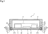
- FIG. 1 is a schematic configuration diagram illustrating a shield case 1 according to a first embodiment.
- the shield case 1 illustrated in FIG. 1 is a case in which an electronic component 2 is stored.
- the shield case 1 is constituted by a base portion 3 on which the electronic component 2 is mounted, a cover portion 4 covering the surroundings of the electronic component 2, and a metal plate 5 abutting with an outer surface 31 of the base portion 3.
- the electronic component 2 is an inverter mounted in a vehicle or the like, for example.
- the shield case 1 prevents an electromagnetic wave generated from the electronic component 2 from being radiated to outside the case and also prevents the electromagnetic wave from entering the case from outside the case and causing malfunction of the electronic component 2.
- the base portion 3 is made of an insulating nonmetal material such as resin, for example, and the electronic component 2 is mounted on a mounting surface 32 of the base portion 3.
- a cooling passage (not shown) through which refrigerant to cool off the electronic component 2 flows is formed inside the base portion 3.
- the cover portion 4 is made of a metal material such as aluminum, for example, and covers the surroundings of the electronic component 2.
- An end portion 41 (a side-wall end portion 41) of a side wall 40 of the cover portion 4 abuts with the mounting surface 32 of the base portion 3 and an end portion 51 of the metal plate 5. Note that details of an abutment structure for the cover portion 4, the base portion 3, and the metal plate 5 will be described later.
- the metal plate 5 is provided so as to abut with the outer surface 31 of the base portion 3.
- An outer shape of the metal plate 5 is formed to be larger than an outer shape of the outer surface 31 of the base portion 3, and the end portion 51 placed on an outer peripheral edge of the metal plate 5 projects outward from the base portion 3.
- the cover portion 4 is configured such that the end portion 41 (the side-wall end portion 41) of the side wall 40 abuts with an end portion 33 placed on an outer peripheral edge of the mounting surface 32 of the base portion 3 and the end portion 51 placed on the outer peripheral edge of the metal plate 5.
- the cover portion 4, the base portion 3, and the metal plate 5 are fastened jointly by a bolt 6 (a fastening member).
- the side-wall end portion 41 of the cover portion 4 includes a first end 411 an end surface 414 of which abuts with the mounting surface 32 of the base portion 3, and a second end 412 extending in a thickness direction of the base portion 3 from a part outward from the first end 411.
- An inner side face, in the thickness direction of the base portion 3, of the second end 412 abuts with the base portion 3, and a distal surface 415 of the second end 412 abuts with the end portion 51 of the metal plate 5.
- the inner side face of the second end 412 may not necessarily abut with the base portion 3.
- An internal thread is cut in a central part of the end surface 414 of the first end 411 so that a bolt can be fastened, and respective through-holes for the bolt are provided in the base portion 3 and the metal plate 5, at respective positions corresponding to the internal thread, the positions being close to the end portions of the base portion 3 and the metal plate 5.
- a cylindrical collar made of metal or the like is inserted into the through-hole provided in the base portion 3 so as to prevent the fastened bolt from being loosened.
- the metal plate 5 have a thickness that allows the metal plate 5 to deform by a fastening force when the metal plate 5 is fastened jointly by the bolt 6.
- the thickness of the metal plate 5 is not limited to this.
- a seal groove (not shown) is provided in the first end 411, at a position closer to an inner side than the position where the bolt 6 is screwed, and a sealing member such as an O-ring is fitted into the seal groove.
- the shield case 1 of the first embodiment described above can yield the following effects.
- the shield case 1 includes the metal plate 5 abutting with the outer surface 31 of the base portion 3 made of a nonmetal material.
- machining can be easily performed, and a cost reduction can be achieved.
- the metal plate 5 is provided so as to abut with the outer surface 31 of the base portion 3, it is not necessary to provide the metal plate 5 having a shape that avoids a cooling passage formed inside the base portion 3.
- the metal plate 5 is provided inside the base portion 3, it is possible to secure an excellent shielding property.
- the side-wall end portion 41 of the cover portion 4 made of a metal material includes the second end 412 extending in the thickness direction of the base portion 3.
- the distal surface 415 of the second end 412 abuts with the end portion 51 of the metal plate 5.
- the electronic component 2 is completely covered with metal members, that is, the cover portion 4 and the metal plate 5. Accordingly, even in a case where the base portion 3 is made of a nonmetal material, it is possible to secure an excellent shielding property.
- a setting direction of the shield case 1 can be determined to be any direction.
- the shield case 1 may be provided in a reverse manner in the up-down direction from the state in FIG. 1 so that the metal plate 5 is placed on the upper side and the cover portion 4 is placed on the lower side, or the shield case 1 may be provided in an inclined state.
- the following describes the shield case 1 according to a second embodiment.
- FIG. 2 is a schematic configuration diagram illustrating the shield case 1 according to the second embodiment.
- the second embodiment is different from the shield case 1 of the first embodiment in that the side-wall end portion 41 of the cover portion 4 includes an extension portion 413 extending toward an outside direction of the shield case 1.
- a constituent having the same function as a constituent in the first embodiment has the same reference sign as the constituent in the first embodiment, and descriptions are made by omitting redundant descriptions appropriately.
- the side-wall end portion 41 of the cover portion 4 includes the first end 411 the end surface 414 of which abuts with the mounting surface 32 of the base portion 3, the extension portion 413 extending toward the outside direction of the shield case 1 from the first end 411, and the second end 412 extending from the extension portion 413 toward the metal plate 5 such that the distal surface 415 abuts with the end portion 51 of the metal plate 5.
- the extension portion 413 connects the first end 411 to the second end 412.
- a bottom face 416 of the extension portion 413 and the end surface 414 of the first end 411 form one plane and abut with the mounting surface 32 of the base portion 3.
- a width of an abutment plane between the side-wall end portion 41 of the cover portion 4 and the mounting surface 32 of the base portion 3 becomes large.
- An internal thread is cut in a central part of the bottom face 416 of the extension portion 413 so that a bolt can be fastened thereto, and respective through-holes for the bolt are provided in the base portion 3 and the metal plate 5, at respective positions corresponding to the internal thread, the positions being close to the end portions of the base portion 3 and the metal plate 5.
- a cylindrical collar made of metal or the like is inserted into the through-hole provided in the base portion 3.
- a seal groove 71 is provided on the bottom face 416 of the extension portion 413, at a position closer to the inner side than the position where the bolt 6 is screwed, and a sealing member such as a gasket 7 is fitted into the seal groove 71.
- the seal groove 71 is formed on the bottom face 416 of the extension portion 413.
- the position where the seal groove 71 is formed is not limited to this, provided that the position is closer to the inner side than the position where the bolt 6 is screwed.
- the seal groove 71 may be formed on the end surface 414 of the first end 411 or may be formed over the end surface 414 of the first end 411 and the bottom face 416 of the extension portion 413.
- the shield case 1 of the second embodiment described above can yield the following effects.
- the side-wall end portion 41 of the cover portion 4 includes the extension portion 413 extending toward the outside direction of the shield case 1 and connecting the first end 411 to the second end 412.
- the bolt 6 by which the cover portion 4, the base portion 3, and the metal plate 5 are fastened jointly is screwed into the internal thread cut in the extension portion 413. Accordingly, it is not necessary to secure the width of the end surface 414 of the first end 411 so that the bolt 6 is screwed into the end surface 414, thereby resulting in that the thickness of the side wall 40 can be made thin.
- the side-wall end portion 41 of the cover portion 4 does not include the extension portion 413, it is possible to achieve a weight reduction and a cost reduction.
- the shield case 1 includes the extension portion 413 extending toward the outside direction of the shield case 1, and the bottom face 416 of the extension portion 413 and the end surface 414 of the first end 411 form one plane and abut with the mounting surface 32 of the base portion 3.
- the width of the abutment plane between the side-wall end portion 41 of the cover portion 4 and the mounting surface 32 of the base portion 3 becomes large.
- the seal groove 71 can be provided as a gasket groove, and a rubber gasket can be selected as a sealing member. This improves a sealing property of the cover portion 4 and the base portion 3.
- the setting direction of the shield case 1 can be determined to be any direction.
- the shield case 1 may be provided in a reverse manner in the up-down direction from the state in FIG. 2 so that the metal plate 5 is placed on the upper side and the cover portion 4 is placed on the lower side, or the shield case 1 may be provided in an inclined state.
- the orientation of the bolt 6 be also reversed in the up-down direction, and the cover portion 4, the base portion 3, and the metal plate 5 be fastened jointly by the bolt 6 by use of a weld nut from the extension portion 413 side of the side-wall end portion 41 of the cover portion.
- the following describes the shield case 1 according to a third embodiment.
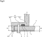
- FIG. 3 is a partial enlarged view illustrating abutment parts of the cover portion 4 with the base portion 3 and the metal plate 5 in the shield case 1 according to the third embodiment.
- the third embodiment is different from the shield case 1 of the second embodiment in that a length Hi, in the thickness direction of the base portion 3, of the second end 412 in the side-wall end portion 41 of the cover portion 4 is longer than a thickness H 2 of the base portion 3.
- the length Hi, in the thickness direction of the base portion 3, of the second end 412 in the side-wall end portion 41 of the cover portion 4 is made longer than the thickness H 2 of the base portion 3.
- a cylindrical collar made of metal or the like is inserted into the through-hole, in the base portion 3, through which the bolt 6 is passed.
- the collar may project from one end of the through-hole of the base portion 3.
- the length Hi, in the thickness direction of the base portion 3, of the second end 412 in the side-wall end portion 41 of the cover portion is formed to be longer than a length of the collar in its cylindrical direction.
- the thickness of the metal plate 5 is set to a thickness t that allows the metal plate 5 to deform when the cover portion 4, the base portion 3, and the metal plate 5 are fastened jointly by the bolt 6.
- the end portion 51 of the metal plate 5 is pressed against the base portion 3 while the end portion 51 abuts with the distal surface 415 of the second end 412 in the side-wall end portion 41 of the cover portion 4, and then, as illustrated in FIG. 3 , the end portion 51 deforms while the end portion 51 abuts with the distal surface 415 of the second end 412.
- the cover portion 4 abuts with the metal plate 5 more firmly without any gap, so that a high shielding property is secured.
- the thickness t of the metal plate 5 is determined based on a shielding characteristic, a deformation characteristic, and stress of a material of the metal 5.
- the shielding characteristic of the material is a characteristic of each type of material in terms of a relationship between the thickness t and the shielding property of the metal plate 5
- the deformation characteristic of the material is a characteristic of each type of material in terms of a relationship between the thickness t of the metal plate 5 and a deformation amount d of the metal plate 5 in a case where the same force is applied to the metal plate 5.
- the stress as used herein is a resisting force caused in a deformed part when the metal plate 5 deforms.
- the following describes a validity range of the thickness t of the metal plate 5.
- the material of the metal plate 5 aluminum, iron, copper, and so on can be considered.
- FIG. 4 is a graph illustrating a relationship between the material, the thickness t, and the shielding property of the metal plate 5.
- the shielding property of the metal plate 5 is taken as a reference value 1 when the metal plate 5 is made of an aluminum material and the thickness t of the metal plate 5 is 0.8 mm
- the relationship between each material, the thickness t, and the shielding property of the metal plate 5 exhibits a tendency illustrated in FIG. 4 .
- the shielding property improves.
- the metal plate 5 has a shielding property equivalent to that in the case where the aluminum material having a thickness of 0.8 mm is used.
- FIG. 5 is a partial enlarged view illustrating the abutment parts of the cover portion 4 with the base portion 3 and the metal plate 5 in the shield case 1
- FIG. 6 is a graph illustrating the stress and the deformation amount d to the thickness t of the metal plate 5 when the metal plate 5 deforms.
- the calculation is performed by use of a formula of a general rectangular beam in strength of materials.
- a distance (a fastening pitch length) between a bolt by which the cover portion 4, the base portion 3, and the metal plate 5 are fastened jointly and its adjacent bolt is taken as a width of the rectangular beam, and here, the distance is 100 mm.
- a length (a length indicated by L in FIG. 5 ) from a point where the cover portion 4 makes contact with the metal plate 5 to a flange outer periphery of the bolt 6 is taken as a length of the rectangular beam, and here, the length is 18 mm.
- a force to deform the metal plate 5 is a part of a fastening force of the bolt 6, but when a large force is used for deformation of the metal plate 5, a force to fix a component becomes insufficient.
- the fastening force of the bolt 6 is also required as a sealing force between the cover portion 4 and the base portion 3, and therefore, a bolt fastening force to be used for deformation of the metal plate 5 cannot be made so large.
- a force to be used for deformation of the metal plate 5 is 10% of the fastening force of the bolt 6 and is calculated as 474 N.
- the relationship between the material, the thickness t, and the deformation amount d of the metal plate 5 when the above force is applied to the metal plate 5 is as illustrated in FIG. 6 .
- the thickness t of the metal plate 5 should be equal to or less than about 1.2 mm in the case of iron, the thickness t of the metal plate 5 should be equal to or less than about 1.4 mm in the case of copper, and the thickness t of the metal plate 5 should be equal to or less than about 1.7 mm in the case of aluminum.
- the stress is determined by a shape and does not have relation with the type of material. Accordingly, the relationship between the stress caused in a deformed part when the metal plate 5 deforms and the thickness of the metal plate 5 is indicated by one curve illustrated in FIG. 6 . In terms of the stress, it is necessary to determine the thickness t of the metal plate 5 within a range where the stress does not exceed the strength limit of each material.
- FIG. 7 is a graph illustrating an example of a validity range of the thickness t of the metal plate 5.
- the shielding property a case where the shielding property is equal to or more than the reference value 1 is assumed as an achievable range.
- the stress a range where the stress does not exceed the strength limit of each material is assumed as an achievable range.
- the deformation amount d a case where the deformation amount is equal to or more than 0.3 mm is assumed as an achievable range.
- a part where respective achievable ranges of the shielding property, the stress, and the deformation amount overlap each other is the validity range of the thickness t of the metal plate 5, and the thickness t of the metal plate 5 can be determined freely within the range.
- the validity range of the thickness t of the metal plate 5 is determined based on the shielding characteristic and the deformation characteristic of the material of the metal 5 and the stress.
- the shield case 1 according to the third embodiment can yield the following effect in addition to the effects obtained by the shield cases 1 of the first and second embodiments.
- the length H 1 , in the thickness direction of the base portion 3, of the second end 412 of the cover portion 4 is made longer than the thickness H 2 of the base portion 3. Accordingly, when the cover portion 4, the base portion 3, and the metal plate 5 are fastened jointly by the bolt 6, the metal plate 5 deforms while the metal plate 5 abuts with the distal surface 415 of the second end 412. Hereby, the cover portion 4 can abut with the metal plate 5 more firmly without any gap, so that a high shielding property can be secured.
Landscapes
- Engineering & Computer Science (AREA)
- Microelectronics & Electronic Packaging (AREA)
- Shielding Devices Or Components To Electric Or Magnetic Fields (AREA)
- Casings For Electric Apparatus (AREA)
Abstract
Description
- The present invention relates to a shield case in which an electronic component is storable.
- A shield case is configured such that an electronic component is stored therein, and the shield case prevents an electromagnetic wave generated from the electronic component from being radiated to outside the case and prevents the electromagnetic wave from entering the case from outside the case. When the shield case is formed by use of a thick metal material, a shielding property improves. However, this is unfavorable from the viewpoint of weight reduction, cost, and processability. It is necessary to provide, in a base portion on which an electronic component is to be mounted, a passage for cooling the component. In a case where the base portion is made of a nonmetal material, it is difficult to incorporate a metal plate for shielding into the base portion, and it is necessary to incorporate a metal material into an outer periphery of the base portion. Further, in order to secure insulation from the electronic component, it is preferable that the base portion be made of a nonmetal material.
- In a case where a shield case in which an electronic component is stored is made of a nonmetal material, such a technology has been known that a metal plate is provided inside the nonmetal material in consideration of a shielding property. For example, in
JP 2013-110358 A - However, in the shield case described above, the metal plate is provided inside the resin, thereby causing such a problem that machining is difficult and a manufacturing cost increases. Further, in a case where the technology of
JP 2013-110358 A - An object of the present invention is to provide a shield case which can be easily machined and which has an excellent shielding property.
- According to an aspect of this invention, there is provided a shield case including a base portion made of a nonmetal material and having a mounting surface on which the electronic component is mounted, a cover portion made of a metal material and covering surroundings of the electronic component and a metal plate abutting with an outer surface of the base portion and having an end portion projecting outward from the base portion. A side-wall end portion of the cover member includes a first end abutting with the mounting surface of the base portion, and a second end extending in a thickness direction of the base portion and abutting with the end portion of the metal plate.
-
-
FIG. 1 is a schematic configuration diagram illustrating a shield case according to a first embodiment. -
FIG. 2 is a schematic configuration diagram illustrating a shield case according to a second embodiment. -
FIG. 3 is a partial enlarged view illustrating abutment parts of a cover portion with a base portion and a metal plate in a shield case according to a third embodiment. -
FIG. 4 is a graph illustrating a relationship between a material, a thickness, and a shielding property of a metal plate. -
FIG. 5 is a partial enlarged view illustrating the abutment parts of the cover portion with the base portion and the metal plate in the shield case. -
FIG. 6 is a graph illustrating a thickness of the metal plate, a stress caused when the metal plate deforms, and a deformation amount. -
FIG. 7 is a graph illustrating an example of a validity range of the thickness of a metal plate. - With reference to the drawings, the following describes embodiments of the present invention.
-
FIG. 1 is a schematic configuration diagram illustrating ashield case 1 according to a first embodiment. Theshield case 1 illustrated inFIG. 1 is a case in which anelectronic component 2 is stored. - As illustrated in
FIG. 1 , theshield case 1 is constituted by abase portion 3 on which theelectronic component 2 is mounted, acover portion 4 covering the surroundings of theelectronic component 2, and ametal plate 5 abutting with anouter surface 31 of thebase portion 3. - The
electronic component 2 is an inverter mounted in a vehicle or the like, for example. Theshield case 1 prevents an electromagnetic wave generated from theelectronic component 2 from being radiated to outside the case and also prevents the electromagnetic wave from entering the case from outside the case and causing malfunction of theelectronic component 2. - The
base portion 3 is made of an insulating nonmetal material such as resin, for example, and theelectronic component 2 is mounted on amounting surface 32 of thebase portion 3. A cooling passage (not shown) through which refrigerant to cool off theelectronic component 2 flows is formed inside thebase portion 3. - The
cover portion 4 is made of a metal material such as aluminum, for example, and covers the surroundings of theelectronic component 2. An end portion 41 (a side-wall end portion 41) of aside wall 40 of thecover portion 4 abuts with themounting surface 32 of thebase portion 3 and anend portion 51 of themetal plate 5. Note that details of an abutment structure for thecover portion 4, thebase portion 3, and themetal plate 5 will be described later. - The
metal plate 5 is provided so as to abut with theouter surface 31 of thebase portion 3. An outer shape of themetal plate 5 is formed to be larger than an outer shape of theouter surface 31 of thebase portion 3, and theend portion 51 placed on an outer peripheral edge of themetal plate 5 projects outward from thebase portion 3. - Next will be described the abutment structure for the
cover portion 4, thebase portion 3, and themetal plate 5. - As illustrated in
FIG. 1 , thecover portion 4 is configured such that the end portion 41 (the side-wall end portion 41) of theside wall 40 abuts with anend portion 33 placed on an outer peripheral edge of themounting surface 32 of thebase portion 3 and theend portion 51 placed on the outer peripheral edge of themetal plate 5. As will be described later, thecover portion 4, thebase portion 3, and themetal plate 5 are fastened jointly by a bolt 6 (a fastening member). - The side-
wall end portion 41 of thecover portion 4 includes afirst end 411 anend surface 414 of which abuts with themounting surface 32 of thebase portion 3, and asecond end 412 extending in a thickness direction of thebase portion 3 from a part outward from thefirst end 411. An inner side face, in the thickness direction of thebase portion 3, of thesecond end 412 abuts with thebase portion 3, and adistal surface 415 of thesecond end 412 abuts with theend portion 51 of themetal plate 5. Note that the inner side face of thesecond end 412 may not necessarily abut with thebase portion 3. - An internal thread is cut in a central part of the
end surface 414 of thefirst end 411 so that a bolt can be fastened, and respective through-holes for the bolt are provided in thebase portion 3 and themetal plate 5, at respective positions corresponding to the internal thread, the positions being close to the end portions of thebase portion 3 and themetal plate 5. A cylindrical collar made of metal or the like is inserted into the through-hole provided in thebase portion 3 so as to prevent the fastened bolt from being loosened. - When the
bolt 6 is screwed into the internal thread of thefirst end 411 of the side-wall end portion 41 through the through-holes of themetal plate 5 and thebase portion 3 from anouter surface 52 of themetal plate 5, thecover portion 4, thebase portion 3, and themetal plate 5 are fastened jointly and fixed in an integrated manner. Note that it is preferable that themetal plate 5 have a thickness that allows themetal plate 5 to deform by a fastening force when themetal plate 5 is fastened jointly by thebolt 6. However, the thickness of themetal plate 5 is not limited to this. - A seal groove (not shown) is provided in the
first end 411, at a position closer to an inner side than the position where thebolt 6 is screwed, and a sealing member such as an O-ring is fitted into the seal groove. By providing the sealing member at the position closer to the inner side than thebolt 6, it is possible to prevent water or the like from entering theshield case 1 from outside. - The
shield case 1 of the first embodiment described above can yield the following effects. - The
shield case 1 includes themetal plate 5 abutting with theouter surface 31 of thebase portion 3 made of a nonmetal material. Hereby, in comparison with a case where themetal plate 5 is provided inside thebase portion 3, machining can be easily performed, and a cost reduction can be achieved. Further, since themetal plate 5 is provided so as to abut with theouter surface 31 of thebase portion 3, it is not necessary to provide themetal plate 5 having a shape that avoids a cooling passage formed inside thebase portion 3. Hereby, in comparison with a case where themetal plate 5 is provided inside thebase portion 3, it is possible to secure an excellent shielding property. - In the
shield case 1, the side-wall end portion 41 of thecover portion 4 made of a metal material includes thesecond end 412 extending in the thickness direction of thebase portion 3. Thedistal surface 415 of thesecond end 412 abuts with theend portion 51 of themetal plate 5. Hereby, theelectronic component 2 is completely covered with metal members, that is, thecover portion 4 and themetal plate 5. Accordingly, even in a case where thebase portion 3 is made of a nonmetal material, it is possible to secure an excellent shielding property. - Note that a setting direction of the
shield case 1 can be determined to be any direction. For example, theshield case 1 may be provided in a reverse manner in the up-down direction from the state inFIG. 1 so that themetal plate 5 is placed on the upper side and thecover portion 4 is placed on the lower side, or theshield case 1 may be provided in an inclined state. - Referring to
FIG. 2 , the following describes theshield case 1 according to a second embodiment. -
FIG. 2 is a schematic configuration diagram illustrating theshield case 1 according to the second embodiment. The second embodiment is different from theshield case 1 of the first embodiment in that the side-wall end portion 41 of thecover portion 4 includes anextension portion 413 extending toward an outside direction of theshield case 1. Note that, in the following embodiment, a constituent having the same function as a constituent in the first embodiment has the same reference sign as the constituent in the first embodiment, and descriptions are made by omitting redundant descriptions appropriately. - As illustrated in
FIG. 2 , the side-wall end portion 41 of thecover portion 4 includes thefirst end 411 theend surface 414 of which abuts with the mountingsurface 32 of thebase portion 3, theextension portion 413 extending toward the outside direction of theshield case 1 from thefirst end 411, and thesecond end 412 extending from theextension portion 413 toward themetal plate 5 such that thedistal surface 415 abuts with theend portion 51 of themetal plate 5. - The
extension portion 413 connects thefirst end 411 to thesecond end 412. Abottom face 416 of theextension portion 413 and theend surface 414 of thefirst end 411 form one plane and abut with the mountingsurface 32 of thebase portion 3. Hereby, in comparison with a case where the side-wall end portion 41 of thecover portion 4 does not include theextension portion 413, a width of an abutment plane between the side-wall end portion 41 of thecover portion 4 and the mountingsurface 32 of thebase portion 3 becomes large. - An internal thread is cut in a central part of the
bottom face 416 of theextension portion 413 so that a bolt can be fastened thereto, and respective through-holes for the bolt are provided in thebase portion 3 and themetal plate 5, at respective positions corresponding to the internal thread, the positions being close to the end portions of thebase portion 3 and themetal plate 5. A cylindrical collar made of metal or the like is inserted into the through-hole provided in thebase portion 3. - When the
bolt 6 is screwed into the internal thread of theextension portion 413 in the side-wall end portion 41 through the through-holes of themetal plate 5 and thebase portion 3 from theouter surface 52 of themetal plate 5, thecover portion 4, thebase portion 3, and themetal plate 5 are fastened jointly and fixed in an integrated manner. When thebolt 6 is screwed into thefirst end 411, a large width of theend surface 414 of thefirst end 411 into which thebolt 6 is screwed should be secured by thickening a thickness of theside wall 40. In the meantime, in the present embodiment, thebolt 6 is screwed into theextension portion 413. On this account, it is not necessary to secure the width of theend surface 414 of thefirst end 411 so that thebolt 6 is screwed into theend surface 414, thereby resulting in that the thickness of theside wall 40 can be made thin. - A
seal groove 71 is provided on thebottom face 416 of theextension portion 413, at a position closer to the inner side than the position where thebolt 6 is screwed, and a sealing member such as agasket 7 is fitted into theseal groove 71. By providing the sealing member at the position closer to the inner side than thebolt 6, it is possible to prevent water or the like from entering theshield case 1 from outside. - Note that, in the present embodiment, the
seal groove 71 is formed on thebottom face 416 of theextension portion 413. However, the position where theseal groove 71 is formed is not limited to this, provided that the position is closer to the inner side than the position where thebolt 6 is screwed. For example, theseal groove 71 may be formed on theend surface 414 of thefirst end 411 or may be formed over theend surface 414 of thefirst end 411 and thebottom face 416 of theextension portion 413. - The
shield case 1 of the second embodiment described above can yield the following effects. - In the
shield case 1, the side-wall end portion 41 of thecover portion 4 includes theextension portion 413 extending toward the outside direction of theshield case 1 and connecting thefirst end 411 to thesecond end 412. Thebolt 6 by which thecover portion 4, thebase portion 3, and themetal plate 5 are fastened jointly is screwed into the internal thread cut in theextension portion 413. Accordingly, it is not necessary to secure the width of theend surface 414 of thefirst end 411 so that thebolt 6 is screwed into theend surface 414, thereby resulting in that the thickness of theside wall 40 can be made thin. Hereby, in comparison with a case where thebolt 6 is screwed into thefirst end 411, that is, the side-wall end portion 41 of thecover portion 4 does not include theextension portion 413, it is possible to achieve a weight reduction and a cost reduction. - The
shield case 1 includes theextension portion 413 extending toward the outside direction of theshield case 1, and thebottom face 416 of theextension portion 413 and theend surface 414 of thefirst end 411 form one plane and abut with the mountingsurface 32 of thebase portion 3. Hereby, in comparison with a case where the side-wall end portion 41 of thecover portion 4 does not include theextension portion 413, the width of the abutment plane between the side-wall end portion 41 of thecover portion 4 and the mountingsurface 32 of thebase portion 3 becomes large. Hereby, it is possible to secure a large width of a plane for sealing thecover portion 4 and thebase portion 3. On this account, a degree of freedom of a sealing structure increases. For example, theseal groove 71 can be provided as a gasket groove, and a rubber gasket can be selected as a sealing member. This improves a sealing property of thecover portion 4 and thebase portion 3. - Note that, similarly to the first embodiment, the setting direction of the
shield case 1 can be determined to be any direction. For example, theshield case 1 may be provided in a reverse manner in the up-down direction from the state inFIG. 2 so that themetal plate 5 is placed on the upper side and thecover portion 4 is placed on the lower side, or theshield case 1 may be provided in an inclined state. In a case where theshield case 1 is provided in a reverse manner in the up-down direction, in order to prevent water or the like from entering theshield case 1 through the through-hole for thebolt 6, it is preferable that the orientation of thebolt 6 be also reversed in the up-down direction, and thecover portion 4, thebase portion 3, and themetal plate 5 be fastened jointly by thebolt 6 by use of a weld nut from theextension portion 413 side of the side-wall end portion 41 of the cover portion. - Referring to
FIGS. 3 and4 , the following describes theshield case 1 according to a third embodiment. -
FIG. 3 is a partial enlarged view illustrating abutment parts of thecover portion 4 with thebase portion 3 and themetal plate 5 in theshield case 1 according to the third embodiment. The third embodiment is different from theshield case 1 of the second embodiment in that a length Hi, in the thickness direction of thebase portion 3, of thesecond end 412 in the side-wall end portion 41 of thecover portion 4 is longer than a thickness H2 of thebase portion 3. - As illustrated in
FIG. 3 , the length Hi, in the thickness direction of thebase portion 3, of thesecond end 412 in the side-wall end portion 41 of thecover portion 4 is made longer than the thickness H2 of thebase portion 3. - Similarly to the first and second embodiments, a cylindrical collar made of metal or the like is inserted into the through-hole, in the
base portion 3, through which thebolt 6 is passed. The collar may project from one end of the through-hole of thebase portion 3. In this case, the length Hi, in the thickness direction of thebase portion 3, of thesecond end 412 in the side-wall end portion 41 of the cover portion is formed to be longer than a length of the collar in its cylindrical direction. - The thickness of the
metal plate 5 is set to a thickness t that allows themetal plate 5 to deform when thecover portion 4, thebase portion 3, and themetal plate 5 are fastened jointly by thebolt 6. - When the
cover portion 4, thebase portion 3, and themetal plate 5 are fastened jointly by thebolt 6, theend portion 51 of themetal plate 5 is pressed against thebase portion 3 while theend portion 51 abuts with thedistal surface 415 of thesecond end 412 in the side-wall end portion 41 of thecover portion 4, and then, as illustrated inFIG. 3 , theend portion 51 deforms while theend portion 51 abuts with thedistal surface 415 of thesecond end 412. Hereby, thecover portion 4 abuts with themetal plate 5 more firmly without any gap, so that a high shielding property is secured. - Note that, the thickness t of the
metal plate 5 is determined based on a shielding characteristic, a deformation characteristic, and stress of a material of themetal 5. The shielding characteristic of the material is a characteristic of each type of material in terms of a relationship between the thickness t and the shielding property of themetal plate 5, and the deformation characteristic of the material is a characteristic of each type of material in terms of a relationship between the thickness t of themetal plate 5 and a deformation amount d of themetal plate 5 in a case where the same force is applied to themetal plate 5. Further, the stress as used herein is a resisting force caused in a deformed part when themetal plate 5 deforms. - With reference to
FIGS. 4 to 6 , the following describes a validity range of the thickness t of themetal plate 5. As the material of themetal plate 5, aluminum, iron, copper, and so on can be considered. -
FIG. 4 is a graph illustrating a relationship between the material, the thickness t, and the shielding property of themetal plate 5. In a case where the shielding property of themetal plate 5 is taken as areference value 1 when themetal plate 5 is made of an aluminum material and the thickness t of themetal plate 5 is 0.8 mm, the relationship between each material, the thickness t, and the shielding property of themetal plate 5 exhibits a tendency illustrated inFIG. 4 . As illustrated inFIG. 4 , in any material, as the thickness t of themetal plate 5 is larger, the shielding property improves. Further, it is found that, in a case of iron or copper, when the thickness is around 0.15 mm, themetal plate 5 has a shielding property equivalent to that in the case where the aluminum material having a thickness of 0.8 mm is used. -
FIG. 5 is a partial enlarged view illustrating the abutment parts of thecover portion 4 with thebase portion 3 and themetal plate 5 in theshield case 1, andFIG. 6 is a graph illustrating the stress and the deformation amount d to the thickness t of themetal plate 5 when themetal plate 5 deforms. Here, the calculation is performed by use of a formula of a general rectangular beam in strength of materials. - A distance (a fastening pitch length) between a bolt by which the
cover portion 4, thebase portion 3, and themetal plate 5 are fastened jointly and its adjacent bolt is taken as a width of the rectangular beam, and here, the distance is 100 mm. Secondly, a length (a length indicated by L inFIG. 5 ) from a point where thecover portion 4 makes contact with themetal plate 5 to a flange outer periphery of thebolt 6 is taken as a length of the rectangular beam, and here, the length is 18 mm. - A force to deform the
metal plate 5 is a part of a fastening force of thebolt 6, but when a large force is used for deformation of themetal plate 5, a force to fix a component becomes insufficient. The fastening force of thebolt 6 is also required as a sealing force between thecover portion 4 and thebase portion 3, and therefore, a bolt fastening force to be used for deformation of themetal plate 5 cannot be made so large. In view of this, a force to be used for deformation of themetal plate 5 is 10% of the fastening force of thebolt 6 and is calculated as 474 N. - The relationship between the material, the thickness t, and the deformation amount d of the
metal plate 5 when the above force is applied to themetal plate 5 is as illustrated inFIG. 6 . As illustrated inFIG. 6 , even with the same thickness t, for example, iron has a smaller deformation amount d than those of copper and aluminum. Further, for example, when it is considered that a deformation amount d equal to or more than 0.3 mm is required, the thickness t of themetal plate 5 should be equal to or less than about 1.2 mm in the case of iron, the thickness t of themetal plate 5 should be equal to or less than about 1.4 mm in the case of copper, and the thickness t of themetal plate 5 should be equal to or less than about 1.7 mm in the case of aluminum. - The stress is determined by a shape and does not have relation with the type of material. Accordingly, the relationship between the stress caused in a deformed part when the
metal plate 5 deforms and the thickness of themetal plate 5 is indicated by one curve illustrated inFIG. 6 . In terms of the stress, it is necessary to determine the thickness t of themetal plate 5 within a range where the stress does not exceed the strength limit of each material. -
FIG. 7 is a graph illustrating an example of a validity range of the thickness t of themetal plate 5. In terms of the shielding property, a case where the shielding property is equal to or more than thereference value 1 is assumed as an achievable range. In terms of the stress, a range where the stress does not exceed the strength limit of each material is assumed as an achievable range. In terms of the deformation amount d, a case where the deformation amount is equal to or more than 0.3 mm is assumed as an achievable range. A part where respective achievable ranges of the shielding property, the stress, and the deformation amount overlap each other is the validity range of the thickness t of themetal plate 5, and the thickness t of themetal plate 5 can be determined freely within the range. - As such, the validity range of the thickness t of the
metal plate 5 is determined based on the shielding characteristic and the deformation characteristic of the material of themetal 5 and the stress. - The
shield case 1 according to the third embodiment can yield the following effect in addition to the effects obtained by theshield cases 1 of the first and second embodiments. - The length H1, in the thickness direction of the
base portion 3, of thesecond end 412 of thecover portion 4 is made longer than the thickness H2 of thebase portion 3. Accordingly, when thecover portion 4, thebase portion 3, and themetal plate 5 are fastened jointly by thebolt 6, themetal plate 5 deforms while themetal plate 5 abuts with thedistal surface 415 of thesecond end 412. Hereby, thecover portion 4 can abut with themetal plate 5 more firmly without any gap, so that a high shielding property can be secured. - The embodiments of the present invention have been described above, but the embodiments just show some applications of the present invention and are not intended to limit the technical scope of the present invention to the concrete configurations of the embodiments.
- Each of the embodiments described above has been described as an independent embodiment, but the embodiments may be combined appropriately.
Claims (6)
- A shield case in which an electronic component is storable, the shield case comprising:a base portion made of a nonmetal material and having a mounting surface on which the electronic component is mounted;a cover portion made of a metal material and covering surroundings of the electronic component; anda metal plate abutting with an outer surface of the base portion and having an end portion projecting outward from the base portion, whereina side-wall end portion of the cover member includes a first end abutting with the mounting surface of the base portion, and a second end extending in a thickness direction of the base portion and abutting with the end portion of the metal plate.
- The shield case according to claim 1, further comprising
a fastening member by which the metal plate, the base portion, and the first end of the cover portion are fastened jointly in the thickness direction of the base portion, wherein
the metal plate is configured to have a thickness that allows the metal plate to deform when the metal plate is fastened jointly. - The shield case according to claim 1, wherein:the cover portion further includes an extension portion connecting the first end to the second end; andthe extension portion extends toward an outside direction of the shield case and has a bottom face abutting with the mounting surface of the base portion.
- The shield case according to claim 3, further comprising
a fastening member by which the metal plate, the base portion, and the extension portion of the cover portion are fastened jointly in the thickness direction of the base portion, wherein
the metal plate is configured to have a thickness that allows the metal plate to deform when the metal plate is fastened jointly. - The shield case according to any one of claims 1 to 4, wherein
a length of the second end in the thickness direction of the base portion is longer than a thickness of the base portion. - The shield case according to any one of claims 1 to 5, wherein
the thickness of the metal plate is determined based on a shielding characteristic and a deformation characteristic of a material of the metal plate and a stress caused in a deformed part when the metal plate deforms.
Applications Claiming Priority (1)
| Application Number | Priority Date | Filing Date | Title |
|---|---|---|---|
| PCT/IB2018/000713 WO2019220166A1 (en) | 2018-05-18 | 2018-05-18 | Shield case |
Publications (3)
| Publication Number | Publication Date |
|---|---|
| EP3796769A1 true EP3796769A1 (en) | 2021-03-24 |
| EP3796769A4 EP3796769A4 (en) | 2021-05-19 |
| EP3796769B1 EP3796769B1 (en) | 2023-02-15 |
Family
ID=68539612
Family Applications (1)
| Application Number | Title | Priority Date | Filing Date |
|---|---|---|---|
| EP18919059.8A Active EP3796769B1 (en) | 2018-05-18 | 2018-05-18 | Shield case |
Country Status (5)
| Country | Link |
|---|---|
| US (1) | US11589485B2 (en) |
| EP (1) | EP3796769B1 (en) |
| JP (1) | JP7220212B2 (en) |
| CN (1) | CN112136372B (en) |
| WO (1) | WO2019220166A1 (en) |
Families Citing this family (2)
| Publication number | Priority date | Publication date | Assignee | Title |
|---|---|---|---|---|
| JP7478637B2 (en) * | 2020-09-29 | 2024-05-07 | ダイキョーニシカワ株式会社 | Electromagnetic wave shielding box |
| JP7512320B2 (en) * | 2022-04-11 | 2024-07-08 | 株式会社ソニー・インタラクティブエンタテインメント | Electronics |
Family Cites Families (24)
| Publication number | Priority date | Publication date | Assignee | Title |
|---|---|---|---|---|
| JPS51113145U (en) | 1975-02-20 | 1976-09-13 | ||
| DE4218112B4 (en) | 1992-01-21 | 2012-03-01 | Robert Bosch Gmbh | Electrical apparatus, in particular switching and control apparatus for motor vehicles |
| JPH05243695A (en) | 1992-03-03 | 1993-09-21 | Fujitsu Ltd | Printed wiring board unit with built-in heat pipe |
| JP2586966Y2 (en) | 1993-07-30 | 1998-12-14 | 株式会社ケーヒン | Electronic component storage case |
| JP2845817B2 (en) * | 1996-06-24 | 1999-01-13 | 福島日本電気株式会社 | Electronic board shield structure and manufacturing method |
| US6065530A (en) * | 1997-05-30 | 2000-05-23 | Alcatel Usa Sourcing, L.P. | Weatherproof design for remote transceiver |
| JP4140100B2 (en) | 1998-10-29 | 2008-08-27 | ソニー株式会社 | Printed wiring board with built-in heat pipe |
| JP2003069270A (en) * | 2001-08-24 | 2003-03-07 | Nissan Motor Co Ltd | Cooling enclosure |
| JP3931620B2 (en) * | 2001-10-25 | 2007-06-20 | 日産自動車株式会社 | Electronic unit housing structure |
| DE10233318C1 (en) * | 2002-07-22 | 2003-09-25 | Siemens Ag | Interference suppression device for electronic apparatus uses capacitor connected between plug element for apparatus circuit and housing potential |
| JP4124137B2 (en) * | 2004-02-23 | 2008-07-23 | 日産自動車株式会社 | Electronic unit housing |
| JP2006245421A (en) | 2005-03-04 | 2006-09-14 | Nissan Motor Co Ltd | Cooling enclosure |
| JP2006294754A (en) * | 2005-04-07 | 2006-10-26 | Denso Corp | Heat dissipation structure for electronic devices |
| JP5287492B2 (en) * | 2009-05-18 | 2013-09-11 | 株式会社デンソー | Electronic equipment |
| HUE030974T2 (en) * | 2010-04-20 | 2017-06-28 | Interplex Prec Tech (Singapore) Pte Ltd | Electromagnetic interference shielding arrangement |
| JP2011233726A (en) * | 2010-04-28 | 2011-11-17 | Kojima Press Industry Co Ltd | Cooling case for electronic parts |
| JP2013110358A (en) | 2011-11-24 | 2013-06-06 | Nissan Motor Co Ltd | Shield case and attachment structure |
| JP6020054B2 (en) * | 2012-11-05 | 2016-11-02 | 株式会社デンソー | High frequency module |
| US9215833B2 (en) * | 2013-03-15 | 2015-12-15 | Apple Inc. | Electronic device with heat dissipating electromagnetic interference shielding structures |
| JP6077928B2 (en) | 2013-05-20 | 2017-02-08 | 富士重工業株式会社 | Electronic device storage case |
| JP6251381B2 (en) * | 2014-03-25 | 2017-12-20 | 京セラ株式会社 | Channel member and semiconductor module |
| CN105992477A (en) * | 2015-01-29 | 2016-10-05 | 鸿富锦精密工业(武汉)有限公司 | Electronic device shell |
| US10225964B2 (en) * | 2016-03-31 | 2019-03-05 | Apple Inc. | Component shielding structures with magnetic shielding |
| EP3768051B1 (en) | 2018-03-12 | 2023-02-15 | Nissan Motor Co., Ltd. | Housing for electronic component |
-
2018
- 2018-05-18 WO PCT/IB2018/000713 patent/WO2019220166A1/en not_active Ceased
- 2018-05-18 EP EP18919059.8A patent/EP3796769B1/en active Active
- 2018-05-18 JP JP2020519192A patent/JP7220212B2/en active Active
- 2018-05-18 CN CN201880093288.8A patent/CN112136372B/en active Active
- 2018-05-18 US US17/055,296 patent/US11589485B2/en active Active
Also Published As
| Publication number | Publication date |
|---|---|
| US11589485B2 (en) | 2023-02-21 |
| EP3796769A4 (en) | 2021-05-19 |
| EP3796769B1 (en) | 2023-02-15 |
| WO2019220166A1 (en) | 2019-11-21 |
| CN112136372B (en) | 2023-07-14 |
| US20210185864A1 (en) | 2021-06-17 |
| JP7220212B2 (en) | 2023-02-09 |
| JPWO2019220166A1 (en) | 2021-05-27 |
| CN112136372A (en) | 2020-12-25 |
Similar Documents
| Publication | Publication Date | Title |
|---|---|---|
| JP4124137B2 (en) | Electronic unit housing | |
| CN103597683B (en) | Sealing ring | |
| JP6472462B2 (en) | Electronic control unit | |
| US9941809B2 (en) | Inverter device | |
| KR20200007043A (en) | Electric drive and electric power steering | |
| US11589485B2 (en) | Shield case | |
| US20080011001A1 (en) | Outdoor unit of air conditioner | |
| KR20190059818A (en) | Lower grille assembly preventing light leakage | |
| US11480184B2 (en) | Hermetic compressor | |
| US11439048B2 (en) | Electronic component housing | |
| US9901004B2 (en) | Housing for electronic control unit | |
| WO2019031172A1 (en) | Electric power conversion device | |
| JP6636363B2 (en) | Mounting structure of mounting member and mounting structure of electronic control unit | |
| JP2016197687A (en) | Electronic control device | |
| JP6950253B2 (en) | Electronic device | |
| JP2008279847A (en) | Electronic equipment | |
| US20240396400A1 (en) | Rotary electric machine | |
| US20130200075A1 (en) | Casing | |
| JP5113648B2 (en) | Assembly parts | |
| JP2019200837A (en) | Fitting structure of connector assembly to frame | |
| US20250253633A1 (en) | Cover tabs for electromagnetic compatibility in junction box | |
| JP2015094434A (en) | Fastening structure for dissimilar metal parts | |
| WO1998053655A1 (en) | Shielded case | |
| WO2022176900A1 (en) | Power conversion device | |
| JP2019176108A (en) | Module case |
Legal Events
| Date | Code | Title | Description |
|---|---|---|---|
| STAA | Information on the status of an ep patent application or granted ep patent |
Free format text: STATUS: THE INTERNATIONAL PUBLICATION HAS BEEN MADE |
|
| PUAI | Public reference made under article 153(3) epc to a published international application that has entered the european phase |
Free format text: ORIGINAL CODE: 0009012 |
|
| STAA | Information on the status of an ep patent application or granted ep patent |
Free format text: STATUS: REQUEST FOR EXAMINATION WAS MADE |
|
| 17P | Request for examination filed |
Effective date: 20201118 |
|
| AK | Designated contracting states |
Kind code of ref document: A1 Designated state(s): AL AT BE BG CH CY CZ DE DK EE ES FI FR GB GR HR HU IE IS IT LI LT LU LV MC MK MT NL NO PL PT RO RS SE SI SK SM TR |
|
| AX | Request for extension of the european patent |
Extension state: BA ME |
|
| A4 | Supplementary search report drawn up and despatched |
Effective date: 20210420 |
|
| RIC1 | Information provided on ipc code assigned before grant |
Ipc: H05K 9/00 20060101AFI20210414BHEP Ipc: H05K 5/02 20060101ALI20210414BHEP Ipc: H05K 5/04 20060101ALI20210414BHEP |
|
| DAV | Request for validation of the european patent (deleted) | ||
| DAX | Request for extension of the european patent (deleted) | ||
| RAP3 | Party data changed (applicant data changed or rights of an application transferred) |
Owner name: RENAULT S.A.S Owner name: NISSAN MOTOR CO., LTD. |
|
| RAP3 | Party data changed (applicant data changed or rights of an application transferred) |
Owner name: RENAULT S.A.S Owner name: NISSAN MOTOR CO., LTD. |
|
| GRAP | Despatch of communication of intention to grant a patent |
Free format text: ORIGINAL CODE: EPIDOSNIGR1 |
|
| STAA | Information on the status of an ep patent application or granted ep patent |
Free format text: STATUS: GRANT OF PATENT IS INTENDED |
|
| INTG | Intention to grant announced |
Effective date: 20221129 |
|
| GRAS | Grant fee paid |
Free format text: ORIGINAL CODE: EPIDOSNIGR3 |
|
| GRAA | (expected) grant |
Free format text: ORIGINAL CODE: 0009210 |
|
| STAA | Information on the status of an ep patent application or granted ep patent |
Free format text: STATUS: THE PATENT HAS BEEN GRANTED |
|
| AK | Designated contracting states |
Kind code of ref document: B1 Designated state(s): AL AT BE BG CH CY CZ DE DK EE ES FI FR GB GR HR HU IE IS IT LI LT LU LV MC MK MT NL NO PL PT RO RS SE SI SK SM TR |
|
| REG | Reference to a national code |
Ref country code: CH Ref legal event code: EP Ref country code: GB Ref legal event code: FG4D |
|
| REG | Reference to a national code |
Ref country code: DE Ref legal event code: R096 Ref document number: 602018046299 Country of ref document: DE |
|
| REG | Reference to a national code |
Ref country code: AT Ref legal event code: REF Ref document number: 1548940 Country of ref document: AT Kind code of ref document: T Effective date: 20230315 Ref country code: IE Ref legal event code: FG4D |
|
| REG | Reference to a national code |
Ref country code: LT Ref legal event code: MG9D |
|
| REG | Reference to a national code |
Ref country code: NL Ref legal event code: MP Effective date: 20230215 |
|
| REG | Reference to a national code |
Ref country code: AT Ref legal event code: MK05 Ref document number: 1548940 Country of ref document: AT Kind code of ref document: T Effective date: 20230215 |
|
| PG25 | Lapsed in a contracting state [announced via postgrant information from national office to epo] |
Ref country code: RS Free format text: LAPSE BECAUSE OF FAILURE TO SUBMIT A TRANSLATION OF THE DESCRIPTION OR TO PAY THE FEE WITHIN THE PRESCRIBED TIME-LIMIT Effective date: 20230215 Ref country code: PT Free format text: LAPSE BECAUSE OF FAILURE TO SUBMIT A TRANSLATION OF THE DESCRIPTION OR TO PAY THE FEE WITHIN THE PRESCRIBED TIME-LIMIT Effective date: 20230615 Ref country code: NO Free format text: LAPSE BECAUSE OF FAILURE TO SUBMIT A TRANSLATION OF THE DESCRIPTION OR TO PAY THE FEE WITHIN THE PRESCRIBED TIME-LIMIT Effective date: 20230515 Ref country code: NL Free format text: LAPSE BECAUSE OF FAILURE TO SUBMIT A TRANSLATION OF THE DESCRIPTION OR TO PAY THE FEE WITHIN THE PRESCRIBED TIME-LIMIT Effective date: 20230215 Ref country code: LV Free format text: LAPSE BECAUSE OF FAILURE TO SUBMIT A TRANSLATION OF THE DESCRIPTION OR TO PAY THE FEE WITHIN THE PRESCRIBED TIME-LIMIT Effective date: 20230215 Ref country code: LT Free format text: LAPSE BECAUSE OF FAILURE TO SUBMIT A TRANSLATION OF THE DESCRIPTION OR TO PAY THE FEE WITHIN THE PRESCRIBED TIME-LIMIT Effective date: 20230215 Ref country code: HR Free format text: LAPSE BECAUSE OF FAILURE TO SUBMIT A TRANSLATION OF THE DESCRIPTION OR TO PAY THE FEE WITHIN THE PRESCRIBED TIME-LIMIT Effective date: 20230215 Ref country code: ES Free format text: LAPSE BECAUSE OF FAILURE TO SUBMIT A TRANSLATION OF THE DESCRIPTION OR TO PAY THE FEE WITHIN THE PRESCRIBED TIME-LIMIT Effective date: 20230215 Ref country code: AT Free format text: LAPSE BECAUSE OF FAILURE TO SUBMIT A TRANSLATION OF THE DESCRIPTION OR TO PAY THE FEE WITHIN THE PRESCRIBED TIME-LIMIT Effective date: 20230215 |
|
| PG25 | Lapsed in a contracting state [announced via postgrant information from national office to epo] |
Ref country code: SE Free format text: LAPSE BECAUSE OF FAILURE TO SUBMIT A TRANSLATION OF THE DESCRIPTION OR TO PAY THE FEE WITHIN THE PRESCRIBED TIME-LIMIT Effective date: 20230215 Ref country code: PL Free format text: LAPSE BECAUSE OF FAILURE TO SUBMIT A TRANSLATION OF THE DESCRIPTION OR TO PAY THE FEE WITHIN THE PRESCRIBED TIME-LIMIT Effective date: 20230215 Ref country code: IS Free format text: LAPSE BECAUSE OF FAILURE TO SUBMIT A TRANSLATION OF THE DESCRIPTION OR TO PAY THE FEE WITHIN THE PRESCRIBED TIME-LIMIT Effective date: 20230615 Ref country code: GR Free format text: LAPSE BECAUSE OF FAILURE TO SUBMIT A TRANSLATION OF THE DESCRIPTION OR TO PAY THE FEE WITHIN THE PRESCRIBED TIME-LIMIT Effective date: 20230516 Ref country code: FI Free format text: LAPSE BECAUSE OF FAILURE TO SUBMIT A TRANSLATION OF THE DESCRIPTION OR TO PAY THE FEE WITHIN THE PRESCRIBED TIME-LIMIT Effective date: 20230215 |
|
| PG25 | Lapsed in a contracting state [announced via postgrant information from national office to epo] |
Ref country code: SM Free format text: LAPSE BECAUSE OF FAILURE TO SUBMIT A TRANSLATION OF THE DESCRIPTION OR TO PAY THE FEE WITHIN THE PRESCRIBED TIME-LIMIT Effective date: 20230215 Ref country code: RO Free format text: LAPSE BECAUSE OF FAILURE TO SUBMIT A TRANSLATION OF THE DESCRIPTION OR TO PAY THE FEE WITHIN THE PRESCRIBED TIME-LIMIT Effective date: 20230215 Ref country code: DK Free format text: LAPSE BECAUSE OF FAILURE TO SUBMIT A TRANSLATION OF THE DESCRIPTION OR TO PAY THE FEE WITHIN THE PRESCRIBED TIME-LIMIT Effective date: 20230215 Ref country code: CZ Free format text: LAPSE BECAUSE OF FAILURE TO SUBMIT A TRANSLATION OF THE DESCRIPTION OR TO PAY THE FEE WITHIN THE PRESCRIBED TIME-LIMIT Effective date: 20230215 |
|
| REG | Reference to a national code |
Ref country code: DE Ref legal event code: R097 Ref document number: 602018046299 Country of ref document: DE |
|
| PG25 | Lapsed in a contracting state [announced via postgrant information from national office to epo] |
Ref country code: SK Free format text: LAPSE BECAUSE OF FAILURE TO SUBMIT A TRANSLATION OF THE DESCRIPTION OR TO PAY THE FEE WITHIN THE PRESCRIBED TIME-LIMIT Effective date: 20230215 |
|
| PLBE | No opposition filed within time limit |
Free format text: ORIGINAL CODE: 0009261 |
|
| STAA | Information on the status of an ep patent application or granted ep patent |
Free format text: STATUS: NO OPPOSITION FILED WITHIN TIME LIMIT |
|
| REG | Reference to a national code |
Ref country code: CH Ref legal event code: PL |
|
| PG25 | Lapsed in a contracting state [announced via postgrant information from national office to epo] |
Ref country code: MC Free format text: LAPSE BECAUSE OF FAILURE TO SUBMIT A TRANSLATION OF THE DESCRIPTION OR TO PAY THE FEE WITHIN THE PRESCRIBED TIME-LIMIT Effective date: 20230215 |
|
| 26N | No opposition filed |
Effective date: 20231116 |
|
| REG | Reference to a national code |
Ref country code: BE Ref legal event code: MM Effective date: 20230531 |
|
| PG25 | Lapsed in a contracting state [announced via postgrant information from national office to epo] |
Ref country code: SI Free format text: LAPSE BECAUSE OF FAILURE TO SUBMIT A TRANSLATION OF THE DESCRIPTION OR TO PAY THE FEE WITHIN THE PRESCRIBED TIME-LIMIT Effective date: 20230215 Ref country code: MC Free format text: LAPSE BECAUSE OF FAILURE TO SUBMIT A TRANSLATION OF THE DESCRIPTION OR TO PAY THE FEE WITHIN THE PRESCRIBED TIME-LIMIT Effective date: 20230215 Ref country code: LU Free format text: LAPSE BECAUSE OF NON-PAYMENT OF DUE FEES Effective date: 20230518 Ref country code: LI Free format text: LAPSE BECAUSE OF NON-PAYMENT OF DUE FEES Effective date: 20230531 Ref country code: CH Free format text: LAPSE BECAUSE OF NON-PAYMENT OF DUE FEES Effective date: 20230531 |
|
| REG | Reference to a national code |
Ref country code: IE Ref legal event code: MM4A |
|
| PG25 | Lapsed in a contracting state [announced via postgrant information from national office to epo] |
Ref country code: IE Free format text: LAPSE BECAUSE OF NON-PAYMENT OF DUE FEES Effective date: 20230518 |
|
| PG25 | Lapsed in a contracting state [announced via postgrant information from national office to epo] |
Ref country code: IE Free format text: LAPSE BECAUSE OF NON-PAYMENT OF DUE FEES Effective date: 20230518 |
|
| PG25 | Lapsed in a contracting state [announced via postgrant information from national office to epo] |
Ref country code: IT Free format text: LAPSE BECAUSE OF FAILURE TO SUBMIT A TRANSLATION OF THE DESCRIPTION OR TO PAY THE FEE WITHIN THE PRESCRIBED TIME-LIMIT Effective date: 20230215 Ref country code: BE Free format text: LAPSE BECAUSE OF NON-PAYMENT OF DUE FEES Effective date: 20230531 |
|
| PG25 | Lapsed in a contracting state [announced via postgrant information from national office to epo] |
Ref country code: BG Free format text: LAPSE BECAUSE OF FAILURE TO SUBMIT A TRANSLATION OF THE DESCRIPTION OR TO PAY THE FEE WITHIN THE PRESCRIBED TIME-LIMIT Effective date: 20230215 |
|
| PG25 | Lapsed in a contracting state [announced via postgrant information from national office to epo] |
Ref country code: BG Free format text: LAPSE BECAUSE OF FAILURE TO SUBMIT A TRANSLATION OF THE DESCRIPTION OR TO PAY THE FEE WITHIN THE PRESCRIBED TIME-LIMIT Effective date: 20230215 |
|
| PGFP | Annual fee paid to national office [announced via postgrant information from national office to epo] |
Ref country code: DE Payment date: 20250423 Year of fee payment: 8 |
|
| PGFP | Annual fee paid to national office [announced via postgrant information from national office to epo] |
Ref country code: GB Payment date: 20250423 Year of fee payment: 8 |
|
| PG25 | Lapsed in a contracting state [announced via postgrant information from national office to epo] |
Ref country code: EE Free format text: LAPSE BECAUSE OF FAILURE TO SUBMIT A TRANSLATION OF THE DESCRIPTION OR TO PAY THE FEE WITHIN THE PRESCRIBED TIME-LIMIT Effective date: 20230215 |
|
| PGFP | Annual fee paid to national office [announced via postgrant information from national office to epo] |
Ref country code: FR Payment date: 20250423 Year of fee payment: 8 |
|
| PG25 | Lapsed in a contracting state [announced via postgrant information from national office to epo] |
Ref country code: CY Free format text: LAPSE BECAUSE OF FAILURE TO SUBMIT A TRANSLATION OF THE DESCRIPTION OR TO PAY THE FEE WITHIN THE PRESCRIBED TIME-LIMIT; INVALID AB INITIO Effective date: 20180518 |
|
| PG25 | Lapsed in a contracting state [announced via postgrant information from national office to epo] |
Ref country code: HU Free format text: LAPSE BECAUSE OF FAILURE TO SUBMIT A TRANSLATION OF THE DESCRIPTION OR TO PAY THE FEE WITHIN THE PRESCRIBED TIME-LIMIT; INVALID AB INITIO Effective date: 20180518 |
|
| PG25 | Lapsed in a contracting state [announced via postgrant information from national office to epo] |
Ref country code: TR Free format text: LAPSE BECAUSE OF FAILURE TO SUBMIT A TRANSLATION OF THE DESCRIPTION OR TO PAY THE FEE WITHIN THE PRESCRIBED TIME-LIMIT Effective date: 20230215 |