EP3796330A1 - Methods for operating mode transitions and related infusion devices and systems - Google Patents
Methods for operating mode transitions and related infusion devices and systems Download PDFInfo
- Publication number
- EP3796330A1 EP3796330A1 EP20197746.9A EP20197746A EP3796330A1 EP 3796330 A1 EP3796330 A1 EP 3796330A1 EP 20197746 A EP20197746 A EP 20197746A EP 3796330 A1 EP3796330 A1 EP 3796330A1
- Authority
- EP
- European Patent Office
- Prior art keywords
- operating mode
- operating
- destination
- user
- control module
- Prior art date
- Legal status (The legal status is an assumption and is not a legal conclusion. Google has not performed a legal analysis and makes no representation as to the accuracy of the status listed.)
- Pending
Links
Images


Classifications
-
- G—PHYSICS
- G16—INFORMATION AND COMMUNICATION TECHNOLOGY [ICT] SPECIALLY ADAPTED FOR SPECIFIC APPLICATION FIELDS
- G16H—HEALTHCARE INFORMATICS, i.e. INFORMATION AND COMMUNICATION TECHNOLOGY [ICT] SPECIALLY ADAPTED FOR THE HANDLING OR PROCESSING OF MEDICAL OR HEALTHCARE DATA
- G16H20/00—ICT specially adapted for therapies or health-improving plans, e.g. for handling prescriptions, for steering therapy or for monitoring patient compliance
- G16H20/10—ICT specially adapted for therapies or health-improving plans, e.g. for handling prescriptions, for steering therapy or for monitoring patient compliance relating to drugs or medications, e.g. for ensuring correct administration to patients
- G16H20/17—ICT specially adapted for therapies or health-improving plans, e.g. for handling prescriptions, for steering therapy or for monitoring patient compliance relating to drugs or medications, e.g. for ensuring correct administration to patients delivered via infusion or injection
-
- A—HUMAN NECESSITIES
- A61—MEDICAL OR VETERINARY SCIENCE; HYGIENE
- A61B—DIAGNOSIS; SURGERY; IDENTIFICATION
- A61B5/00—Measuring for diagnostic purposes; Identification of persons
- A61B5/145—Measuring characteristics of blood in vivo, e.g. gas concentration, pH value; Measuring characteristics of body fluids or tissues, e.g. interstitial fluid, cerebral tissue
- A61B5/14532—Measuring characteristics of blood in vivo, e.g. gas concentration, pH value; Measuring characteristics of body fluids or tissues, e.g. interstitial fluid, cerebral tissue for measuring glucose, e.g. by tissue impedance measurement
-
- A—HUMAN NECESSITIES
- A61—MEDICAL OR VETERINARY SCIENCE; HYGIENE
- A61M—DEVICES FOR INTRODUCING MEDIA INTO, OR ONTO, THE BODY; DEVICES FOR TRANSDUCING BODY MEDIA OR FOR TAKING MEDIA FROM THE BODY; DEVICES FOR PRODUCING OR ENDING SLEEP OR STUPOR
- A61M5/00—Devices for bringing media into the body in a subcutaneous, intra-vascular or intramuscular way; Accessories therefor, e.g. filling or cleaning devices, arm-rests
- A61M5/14—Infusion devices, e.g. infusing by gravity; Blood infusion; Accessories therefor
- A61M5/142—Pressure infusion, e.g. using pumps
- A61M5/14212—Pumping with an aspiration and an expulsion action
- A61M5/1424—Manually operated pumps
-
- A—HUMAN NECESSITIES
- A61—MEDICAL OR VETERINARY SCIENCE; HYGIENE
- A61M—DEVICES FOR INTRODUCING MEDIA INTO, OR ONTO, THE BODY; DEVICES FOR TRANSDUCING BODY MEDIA OR FOR TAKING MEDIA FROM THE BODY; DEVICES FOR PRODUCING OR ENDING SLEEP OR STUPOR
- A61M5/00—Devices for bringing media into the body in a subcutaneous, intra-vascular or intramuscular way; Accessories therefor, e.g. filling or cleaning devices, arm-rests
- A61M5/14—Infusion devices, e.g. infusing by gravity; Blood infusion; Accessories therefor
- A61M5/142—Pressure infusion, e.g. using pumps
- A61M5/14244—Pressure infusion, e.g. using pumps adapted to be carried by the patient, e.g. portable on the body
-
- A—HUMAN NECESSITIES
- A61—MEDICAL OR VETERINARY SCIENCE; HYGIENE
- A61M—DEVICES FOR INTRODUCING MEDIA INTO, OR ONTO, THE BODY; DEVICES FOR TRANSDUCING BODY MEDIA OR FOR TAKING MEDIA FROM THE BODY; DEVICES FOR PRODUCING OR ENDING SLEEP OR STUPOR
- A61M5/00—Devices for bringing media into the body in a subcutaneous, intra-vascular or intramuscular way; Accessories therefor, e.g. filling or cleaning devices, arm-rests
- A61M5/14—Infusion devices, e.g. infusing by gravity; Blood infusion; Accessories therefor
- A61M5/168—Means for controlling media flow to the body or for metering media to the body, e.g. drip meters, counters ; Monitoring media flow to the body
- A61M5/172—Means for controlling media flow to the body or for metering media to the body, e.g. drip meters, counters ; Monitoring media flow to the body electrical or electronic
- A61M5/1723—Means for controlling media flow to the body or for metering media to the body, e.g. drip meters, counters ; Monitoring media flow to the body electrical or electronic using feedback of body parameters, e.g. blood-sugar, pressure
-
- G—PHYSICS
- G16—INFORMATION AND COMMUNICATION TECHNOLOGY [ICT] SPECIALLY ADAPTED FOR SPECIFIC APPLICATION FIELDS
- G16H—HEALTHCARE INFORMATICS, i.e. INFORMATION AND COMMUNICATION TECHNOLOGY [ICT] SPECIALLY ADAPTED FOR THE HANDLING OR PROCESSING OF MEDICAL OR HEALTHCARE DATA
- G16H20/00—ICT specially adapted for therapies or health-improving plans, e.g. for handling prescriptions, for steering therapy or for monitoring patient compliance
- G16H20/10—ICT specially adapted for therapies or health-improving plans, e.g. for handling prescriptions, for steering therapy or for monitoring patient compliance relating to drugs or medications, e.g. for ensuring correct administration to patients
- G16H20/13—ICT specially adapted for therapies or health-improving plans, e.g. for handling prescriptions, for steering therapy or for monitoring patient compliance relating to drugs or medications, e.g. for ensuring correct administration to patients delivered from dispensers
-
- G—PHYSICS
- G16—INFORMATION AND COMMUNICATION TECHNOLOGY [ICT] SPECIALLY ADAPTED FOR SPECIFIC APPLICATION FIELDS
- G16H—HEALTHCARE INFORMATICS, i.e. INFORMATION AND COMMUNICATION TECHNOLOGY [ICT] SPECIALLY ADAPTED FOR THE HANDLING OR PROCESSING OF MEDICAL OR HEALTHCARE DATA
- G16H40/00—ICT specially adapted for the management or administration of healthcare resources or facilities; ICT specially adapted for the management or operation of medical equipment or devices
- G16H40/60—ICT specially adapted for the management or administration of healthcare resources or facilities; ICT specially adapted for the management or operation of medical equipment or devices for the operation of medical equipment or devices
- G16H40/63—ICT specially adapted for the management or administration of healthcare resources or facilities; ICT specially adapted for the management or operation of medical equipment or devices for the operation of medical equipment or devices for local operation
-
- A—HUMAN NECESSITIES
- A61—MEDICAL OR VETERINARY SCIENCE; HYGIENE
- A61M—DEVICES FOR INTRODUCING MEDIA INTO, OR ONTO, THE BODY; DEVICES FOR TRANSDUCING BODY MEDIA OR FOR TAKING MEDIA FROM THE BODY; DEVICES FOR PRODUCING OR ENDING SLEEP OR STUPOR
- A61M5/00—Devices for bringing media into the body in a subcutaneous, intra-vascular or intramuscular way; Accessories therefor, e.g. filling or cleaning devices, arm-rests
- A61M5/14—Infusion devices, e.g. infusing by gravity; Blood infusion; Accessories therefor
- A61M5/142—Pressure infusion, e.g. using pumps
- A61M2005/14208—Pressure infusion, e.g. using pumps with a programmable infusion control system, characterised by the infusion program
-
- A—HUMAN NECESSITIES
- A61—MEDICAL OR VETERINARY SCIENCE; HYGIENE
- A61M—DEVICES FOR INTRODUCING MEDIA INTO, OR ONTO, THE BODY; DEVICES FOR TRANSDUCING BODY MEDIA OR FOR TAKING MEDIA FROM THE BODY; DEVICES FOR PRODUCING OR ENDING SLEEP OR STUPOR
- A61M2205/00—General characteristics of the apparatus
- A61M2205/50—General characteristics of the apparatus with microprocessors or computers
- A61M2205/52—General characteristics of the apparatus with microprocessors or computers with memories providing a history of measured variating parameters of apparatus or patient
Definitions
- Embodiments of the subject matter described herein relate generally to medical devices, and more particularly, embodiments of the subject matter relate to managing transitions into fluid infusion device operating modes.
- Infusion pump devices and systems are relatively well known in the medical arts, for use in delivering or dispensing an agent, such as insulin or another prescribed medication, to a patient.
- a typical infusion pump includes a pump drive system which typically includes a small motor and drive train components that convert rotational motor motion to a translational displacement of a plunger (or stopper) in a reservoir that delivers medication from the reservoir to the body of a user via a fluid path created between the reservoir and the body of a user.
- Use of infusion pump therapy has been increasing, especially for delivering insulin for diabetics.
- Continuous insulin infusion provides greater control of a diabetic's condition, and hence, control schemes are being developed that allow insulin infusion pumps to monitor and regulate a user's blood glucose level in a substantially continuous and autonomous manner.
- an insulin infusion pump may operate in a closed-loop operating mode overnight while a user is sleeping to regulate the user's glucose level to a target glucose level.
- multiple different operating modes for providing continuous insulin infusion may be supported by an infusion pump. However, care must be taken when transitioning between operating modes to avoid potentially compromising a user's condition and ensure compliance with applicable regulatory requirements.
- one or more preconditions must be satisfied before entering to a particular operating mode is allowed.
- entry into the operating mode may be denied, which may frustrate a user who would like to operate the infusion pump in that particular operating mode at that particular moment in time.
- various conditions may be encountered while operating the infusion pump in that operating mode that result in generation of alerts, which could be disruptive or distracting to the user.
- One exemplary method involves operating an infusion device to deliver fluid to a user in accordance with a first operating mode of a plurality of operating modes, obtaining operational information pertaining to the first operating mode, and obtaining clinical information pertaining to the user. The method continues by determining a destination operating mode of the plurality of operating modes based at least in part on the operational information and the clinical information, and operating the infusion device to deliver the fluid in accordance with the destination operating mode in a manner that is influenced by at least a portion of the operational information pertaining to the first operating mode.
- an infusion device includes a data storage element to maintain operational information pertaining to a first operating mode of a plurality of operating modes and clinical information pertaining to a user, a motor operable to deliver fluid influencing a physiological condition to a body of the user, and a control system coupled to the motor and the data storage element.
- the control system operates the motor to deliver the fluid in accordance with the first operating mode, determines a destination operating mode of the plurality of operating modes based at least in part on the operational information and the clinical information, and operates the infusion device to deliver the fluid in accordance with the destination operating mode in a manner that is influenced by at least a portion of the operational information pertaining to the first operating mode.
- a method of operating an infusion device operable to deliver insulin to a user involves operating the infusion device to deliver the insulin in accordance with a first operating mode of a plurality of operating modes, obtaining operational information pertaining to the first operating mode, and obtaining one or more glucose values for the user.
- the method continues by determining a set of one or more possible operating modes from the plurality of operating modes based at least in part on the one or more glucose values and the operational information.
- the method selects a destination operating mode from the set of one or more possible operating modes and operates the infusion device to deliver the insulin in accordance with the destination operating mode in a manner that is influenced by at least a portion of the operational information pertaining to the first operating mode.
- the invention also provides an infusion device for a medicinal fluid, the device including: a motor operable to deliver the fluid in response to commands; a management system coupled to the motor for generating said commands; wherein the management system includes: a plurality of control modules each configured to generate said commands in accordance with a different respective operating mode; a supervisory module connected to each of the control modules and configured to monitor the status of the control modules, and to receive a mode transition signal; a command multiplexer connected to each of the control modules, to the motor, and to the supervisory module and configured to direct the said commands from a selected one of the control modules to the motor, in accordance with a selection signal from the supervisory module; the supervisory module being further configured to change the selection signal, upon receipt of the mode transition signal thereby causing the command multiplexer to direct the commands from a different selected one of the control modules to the motor.
- the infusion device may further include a user interface and the mode transition signal may be generated by a user manipulating the user interface.
- the management system may be configured to generate the mode transition signal in response to a predetermined maximum operation time limit being reached by a control module that is generating the commands being sent to the motor.
- the management system may be configured to generate the mode transition signal in response to a unreliability being detected in a control module that is generating the commands being sent to the motor.
- the supervisory module maybe configured to inhibit the selection on receipt of the mode transition signal, of a control module in which an unreliability has been detected.
- the said status may include a prediction of future commands that would be directed to the motor if a respective control module were selected, and the supervisory module may be configured to inhibit the selection on receipt of the mode transition signal, of a control module where the future commands would result in one or more of transgression of a pre-specified maximum suspension time, transgression of a pre-specified maximum delivery limit, and failure to meet a pre-specified minimum delivery threshold.
- the operating modes may be selected from a list comprising open-loop mode, closed-loop mode, LGS mode in which a basal rate of delivery of the medicinal fluid is provided while a physiological analyte level that is controlled by the medicinal fluid is above a threshold and suspended while it is not, and PLGM mode in which a basal rate of delivery of the medicinal fluid is provided while a predicted level of the physiological analyte that is controlled by the medicinal fluid is above a threshold and suspended while it is not.
- the medicinal fluid may be insulin.
- infusion pumps may be of the type described in, but not limited to, United States Patent numbers: 4,562,751 ; 4,685,903 ; 5,080,653 ; 5,505,709 ; 5,097,122 ; 6,485,465 ; 6,554,798 ; 6,558,320 ; 6,558,351 ; 6,641,533 ; 6,659,980 ; 6,752,787 ; 6,817,990 ; 6,932,584 ; and 7,621,893 ; each of which are herein incorporated by reference.
- a fluid infusion devices including a motor that is operable to linearly displace a plunger (or stopper) of a reservoir provided within the fluid infusion device to deliver a dosage of fluid, such as insulin, to the body of a user.
- a dosage of fluid such as insulin
- Dosage commands that govern operation of the motor i.e. the device responsible for directly or indirectly imparting motion to the fluid, may be generated in an automated manner in accordance with the delivery control scheme associated with a particular operating mode.
- the fluid infusion device may be operated in any one of a number of operating modes and be able to switch between the modes.
- Examples of operating modes are closed-loop, predictive, and open-loop.
- the device typically contains algorithms which when executed implement respective ones of the operating modes. In that case switching modes involves switching from one algorithm to another.
- a closed-loop operating mode for example, the dosage commands are generated based on a difference between a current (or most recent) measurement of a physiological condition in the body of the user (e.g., an interstitial fluid glucose level in the case of diabetes management by infusion of insulin) and a target (or reference) value for that physiological condition.
- a predictive operating mode the dosage commands may be influenced by a predicted value (or anticipated measurement) for that physiological condition in the body of the user at some point in the future.
- the dosage commands may be configured to implement a predetermined delivery rate. Such rate may be substantially independent of the current or predicted measurements of the physiological condition of the user.
- transitions between operating modes implemented by the infusion device are also supervised or otherwise managed to maintain satisfactory control of the user's physiological condition and ensure compliance with applicable delivery control rules.
- the delivery control rules may be dictated by regulatory requirements, manufacturer requirements, device settings, user preferences, or the like.
- the destination operating mode is initialized using operational information pertaining to the current operation of the infusion device in the initial operating mode being transitioned from to provide a relatively seamless transition between operating modes.
- information pertaining to the operating mode currently being implemented is obtained before transitioning to the destination operating mode.
- the operational information characterizes the current instance of the current operating mode and may include, for example, delivery or suspension information (e.g., whether or not delivery was suspended at any time, the duration delivery was suspended, and the like), the values of any active timers (e.g., the duration of a current instance of delivery suspension, the duration of a current refractory period, and the like), alert information (e.g., whether or not any alerts where generated, and information identifying what types of alerts were generated or the root cause) and information indicating why the current instance of the current operating mode is being exited.
- delivery or suspension information e.g., whether or not delivery was suspended at any time, the duration delivery was suspended, and the like
- the values of any active timers e.g., the duration of a current instance of delivery suspension, the duration of a current refractory period, and the like
- alert information e.g., whether or not any alerts where generated, and information identifying what types of alerts were generated or the root cause
- At least a portion of the operational information is provided to the destination operating mode upon the transition from the previous operating mode, with the operation of the infusion device in accordance with the destination operating mode being influenced by that operational information.
- the destination operating mode may be initialized with the same timer values or counter values from the preceding operating mode to ensure that no time constraints or other applicable maximum limits are violated by the destination operating mode.
- clinical status information pertaining to the physiological condition of the user is also obtained.
- the clinical information may include, for example, recent or historical sensor measurement values of the physiological condition of the user, reference measurement values of the physiological condition of the user, sensor calibration history for the user, and the like.
- the destination operating mode is automatically determined based at least in part on portions of the clinical information and the operational information for the current operating mode along with the device settings or user preferences establishing a hierarchical order for the operating modes.
- the clinical information and/or the operational information may be used to identify and exclude operating modes that are likely to violate any applicable constraints or requirements upon entry, with the hierarchical information for the operating modes being used to select the most preferable operating mode from among the remaining potential operating modes.
- an infusion system 100 includes, without limitation, a fluid infusion device (or infusion pump) 102, a sensing arrangement 104, a command control device (CCD) 106, and a computer 108.
- the components of an infusion system 100 may be realized using different platforms, designs, and configurations, and the embodiment shown in FIG. 1 is not exhaustive or limiting.
- the infusion device 102 and the sensing arrangement 104 are secured at desired locations on the body of a user (or patient), as illustrated in FIG. 1 .
- the locations at which the infusion device 102 and the sensing arrangement 104 are secured to the body of the user in FIG. 1 are provided only as a representative, non-limiting, example.
- the elements of the infusion system 100 may be similar to those described in United States Patent No. 8,674,288 , the subject matter of which is hereby incorporated by reference in its entirety.
- the infusion device 102 is designed as a portable medical device suitable for infusing a fluid, a liquid, a gel, or other agent into the body of a user.
- the infused fluid is insulin, although many other fluids may be administered through infusion such as, but not limited to, HIV drugs, drugs to treat pulmonary hypertension, iron chelation drugs, pain medications, anti-cancer treatments, medications, vitamins, hormones, or the like.
- the fluid may include a nutritional supplement, a dye, a tracing medium, a saline medium, a hydration medium, or the like.
- the sensing arrangement 104 generally represents the components of the infusion system 100 configured to sense, detect, measure or otherwise quantify a condition of the user, and may include a sensor, a monitor, or the like, for providing data indicative of the condition that is sensed, detected, measured or otherwise monitored by the sensing arrangement.
- the sensing arrangement 104 may include electronics and enzymes reactive to a biological condition, such as a blood glucose level, or the like, of the user, and provide data indicative of the blood glucose level to the infusion device 102, the CCD 106 and/or the computer 108.
- the infusion device 102, the CCD 106 and/or the computer 108 may include a display for presenting information or data to the user based on the sensor data received from the sensing arrangement 104, such as, for example, a current glucose level of the user, a graph or chart of the user's glucose level versus time, device status indicators, alert messages, or the like.
- the infusion device 102, the CCD 106 and/or the computer 108 may include electronics and software that are configured to analyze sensor data and operate the infusion device 102 to deliver fluid to the body of the user based on the sensor data and/or preprogrammed delivery routines.
- one or more of the infusion device 102, the sensing arrangement 104, the CCD 106, and/or the computer 108 includes a transmitter, a receiver, and/or other transceiver electronics that allow for communication with other components of the infusion system 100, so that the sensing arrangement 104 may transmit sensor data or monitor data to one or more of the infusion device 102, the CCD 106 and/or the computer 108.
- the sensing arrangement 104 may be secured to the body of the user or embedded in the body of the user at a location that is remote from the location at which the infusion device 102 is secured to the body of the user. In various other embodiments, the sensing arrangement 104 may be incorporated within the infusion device 102. In other embodiments, the sensing arrangement 104 may be separate and apart from the infusion device 102, and may be, for example, part of the CCD 106. In such embodiments, the sensing arrangement 104 may be configured to receive a biological sample, analyte, or the like, to measure a condition of the user.
- the CCD 106 and/or the computer 108 may include electronics and other components configured to perform processing, delivery routine storage, and to control the infusion device 102 in a manner that is influenced by sensor data measured by and/or received from the sensing arrangement 104.
- the infusion device 102 may be made with more simplified electronics.
- the infusion device 102 may include all control functions, and may operate without the CCD 106 and/or the computer 108.
- the CCD 106 may be a portable electronic device.
- the infusion device 102 and/or the sensing arrangement 104 may be configured to transmit data to the CCD 106 and/or the computer 108 for display or processing of the data by the CCD 106 and/or the computer 108.
- the CCD 106 and/or the computer 108 may provide information to the user that facilitates the user's subsequent use of the infusion device 102.
- the CCD 106 may provide information to the user to allow the user to determine the rate or dose of medication to be administered into the user's body.
- the CCD 106 may provide information to the infusion device 102 to autonomously control the rate or dose of medication administered into the body of the user.
- the sensing arrangement 104 may be integrated into the CCD 106. Such embodiments may allow the user to monitor a condition by providing, for example, a sample of his or her blood to the sensing arrangement 104 to assess his or her condition.
- the sensing arrangement 104 and the CCD 106 may be used for determining glucose levels in the blood and/or body fluids of the user without the use of, or necessity of, a wire or cable connection between the infusion device 102 and the sensing arrangement 104 and/or the CCD 106.
- the sensing arrangement 104 and/or the infusion device 102 are cooperatively configured to utilize a closed-loop system for delivering fluid to the user.
- a closed-loop system for delivering fluid to the user.
- Examples of sensing devices and/or infusion pumps utilizing closed-loop systems may be found at, but are not limited to, the following United States patent numbers: 6,088,608 , 6,119,028 , 6,589,229 , 6,740,072 , 6,827,702 , 7,323,142 , and 7,402, 153 , all of which are incorporated herein by reference in their entirety.
- the sensing arrangement 104 is configured to sense or measure a condition of the user, such as, blood glucose level or the like.
- the infusion device 102 is configured to deliver fluid in response to the condition sensed by the sensing arrangement 104.
- the sensing arrangement 104 continues to sense or otherwise quantify a current condition of the user, thereby allowing the infusion device 102 to deliver fluid continuously in response to the condition currently (or most recently) sensed by the sensing arrangement 104 indefinitely.
- the sensing arrangement 104 and/or the infusion device 102 may be configured to utilize the closed-loop system only for a portion of the day, for example only when the user is asleep or awake.
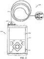
- FIGS. 2-4 depict one exemplary embodiment of a fluid infusion device 200 (or alternatively, infusion pump) suitable for use in an infusion system, such as, for example, as infusion device 102 in the infusion system 100 of FIG. 1 .
- the fluid infusion device 200 is a portable medical device designed to be carried or worn by a patient (or user), and the fluid infusion device 200 may leverage any number of conventional features, components, elements, and characteristics of existing fluid infusion devices, such as, for example, some of the features, components, elements, and/or characteristics described in United States Patent numbers 6,485,465 and 7,621,893 . It should be appreciated that FIGS. 2-4 depict some aspects of the infusion device 200 in a simplified manner; in practice, the infusion device 200 could include additional elements, features, or components that are not shown or described in detail herein.
- the illustrated embodiment of the fluid infusion device 200 includes a housing 202 adapted to receive a fluid-containing reservoir 205.
- An opening 220 in the housing 202 accommodates a fitting 223 (or cap) for the reservoir 205, with the fitting 223 being configured to mate or otherwise interface with tubing 221 of an infusion set 225 that provides a fluid path to/from the body of the user.
- tubing 2221 tubing 2221
- the illustrated fluid infusion device 200 includes a human-machine interface (HMI) 230 (or user interface) that includes elements 232, 234 that can be manipulated by the user to administer a bolus of fluid (e.g., insulin), to change therapy settings, to change user preferences, to select display features, and the like.
- HMI human-machine interface
- the infusion device also includes a display element 226, such as a liquid crystal display (LCD) or another suitable display element, that can be used to present various types of information or data to the user, such as, without limitation: the current glucose level of the patient; the time; a graph or chart of the patient's glucose level versus time; device status indicators; etc.
- LCD liquid crystal display
- the housing 202 is formed from a substantially rigid material having a hollow interior 214 adapted to allow an electronics assembly 204, a sliding member (or slide) 206, a drive system 208, a sensor assembly 210, and a drive system capping member 212 to be disposed therein in addition to the reservoir 205, with the contents of the housing 202 being enclosed by a housing capping member 216.
- the opening 220, the slide 206, and the drive system 208 are coaxially aligned in an axial direction (indicated by arrow 218), whereby the drive system 208 facilitates linear displacement of the slide 206 in the axial direction 218 to dispense fluid from the reservoir 205 (after the reservoir 205 has been inserted into opening 220), with the sensor assembly 210 being configured to measure axial forces (e.g., forces aligned with the axial direction 218) exerted on the sensor assembly 210 responsive to operating the drive system 208 to displace the slide 206.
- axial forces e.g., forces aligned with the axial direction 218
- the sensor assembly 210 may be utilized to detect one or more of the following: an occlusion in a fluid path that slows, prevents, or otherwise degrades fluid delivery from the reservoir 205 to a user's body; when the reservoir 205 is empty; when the slide 206 is properly seated with the reservoir 205; when a fluid dose has been delivered; when the infusion pump 200 is subjected to shock or vibration; when the infusion pump 200 requires maintenance.
- the fluid-containing reservoir 205 may be realized as a syringe, a vial, a cartridge, a bag, or the like.
- the infused fluid is insulin, although many other fluids may be administered through infusion such as, but not limited to, HIV drugs, drugs to treat pulmonary hypertension, iron chelation drugs, pain medications, anti-cancer treatments, medications, vitamins, hormones, or the like.
- the reservoir 205 typically includes a reservoir barrel 219 that contains the fluid and is concentrically and/or coaxially aligned with the slide 206 (e.g., in the axial direction 218) when the reservoir 205 is inserted into the infusion pump 200.
- the end of the reservoir 205 proximate the opening 220 may include or otherwise mate with the fitting 223, which secures the reservoir 205 in the housing 202 and prevents displacement of the reservoir 205 in the axial direction 218 with respect to the housing 202 after the reservoir 205 is inserted into the housing 202.
- the fitting 223 extends from (or through) the opening 220 of the housing 202 and mates with tubing 221 to establish fluid communication from the interior of the reservoir 205 (e.g., reservoir barrel 219) to the user via the tubing 221 and infusion set 225.
- the opposing end of the reservoir 205 proximate the slide 206 includes a plunger 217 (or stopper) positioned to push fluid from inside the barrel 219 of the reservoir 205 along a fluid path through tubing 221 to a user.
- the slide 206 is configured to mechanically couple or otherwise engage with the plunger 217, thereby becoming seated with the plunger 217 and/or reservoir 205. Fluid is forced from the reservoir 205 via tubing 221 as the drive system 208 is operated to displace the slide 206 in the axial direction 218 toward the opening 220 in the housing 202.
- the drive system 208 includes a motor assembly 207 and a drive screw 209.
- the motor assembly 207 includes a motor that is coupled to drive train components of the drive system 208 that are configured to convert rotational motor motion to a translational displacement of the slide 206 in the axial direction 218, and thereby engaging and displacing the plunger 217 of the reservoir 205 in the axial direction 218.
- the motor assembly 207 may also be powered to translate the slide 206 in the opposing direction (e.g., the direction opposite direction 218) to retract and/or detach from the reservoir 205 to allow the reservoir 205 to be replaced.
- the motor assembly 207 includes a brushless DC (BLDC) motor having one or more permanent magnets mounted, affixed, or otherwise disposed on its rotor.
- BLDC brushless DC
- the motor may be realized as a solenoid motor, an AC motor, a stepper motor, a piezoelectric caterpillar drive, a shape memory actuator drive, an electrochemical gas cell, a thermally driven gas cell, a bimetallic actuator, or the like.
- the drive train components may comprise one or more lead screws, cams, ratchets, jacks, pulleys, pawls, clamps, gears, nuts, slides, bearings, levers, beams, stoppers, plungers, sliders, brackets, guides, bearings, supports, bellows, caps, diaphragms, bags, heaters, or the like.
- the illustrated embodiment of the infusion pump utilizes a coaxially aligned drive train
- the motor could be arranged in an offset or otherwise non-coaxial manner, relative to the longitudinal axis of the reservoir 205.
- the drive screw 209 mates with threads 402 internal to the slide 206.
- the motor assembly 207 is powered and operated, the drive screw 209 rotates, and the slide 206 is forced to translate in the axial direction 218.
- the infusion pump 200 includes a sleeve 211 to prevent the slide 206 from rotating when the drive screw 209 of the drive system 208 rotates.
- rotation of the drive screw 209 causes the slide 206 to extend or retract relative to the drive motor assembly 207.
- the slide 206 contacts the plunger 217 to engage the reservoir 205 and control delivery of fluid from the infusion pump 200.
- the shoulder portion 215 of the slide 206 contacts or otherwise engages the plunger 217 to displace the plunger 217 in the axial direction 218.
- the slide 206 may include a threaded tip 213 capable of being detachably engaged with internal threads 404 on the plunger 217 of the reservoir 205, as described in detail in United States patent numbers 6,248,093 and 6,485,465 , which are incorporated by reference herein.
- the electronics assembly 204 includes control electronics 224 coupled to the display element 226, with the housing 202 including a transparent window portion 228 that is aligned with the display element 226 to allow the display 226 to be viewed by the user when the electronics assembly 204 is disposed within the interior 214 of the housing 202.
- the control electronics 224 generally represent the hardware, firmware, processing logic and/or software (or combinations thereof) configured to control operation of the motor assembly 207 and/or drive system 208, as described in greater detail below in the context of FIG. 5 . Whether such functionality is implemented as hardware, firmware, a state machine, or software depends upon the particular application and design constraints imposed on the embodiment.
- control electronics 224 includes one or more programmable controllers that may be programmed to control operation of the infusion pump 200.
- the motor assembly 207 includes one or more electrical leads 236 adapted to be electrically coupled to the electronics assembly 204 to establish communication between the control electronics 224 and the motor assembly 207.
- a motor driver e.g., a power converter
- the motor actuates the drive train components of the drive system 208 to displace the slide 206 in the axial direction 218 to force fluid from the reservoir 205 along a fluid path (including tubing 221 and an infusion set), thereby administering doses of the fluid contained in the reservoir 205 into the user's body.
- the power supply is realized one or more batteries contained within the housing 202.
- the power supply may be a solar panel, capacitor, AC or DC power supplied through a power cord, or the like.
- the control electronics 224 may operate the motor of the motor assembly 207 and/or drive system 208 in a stepwise manner, typically on an intermittent basis; to administer discrete precise doses of the fluid to the user according to programmed delivery profiles.
- the user interface 230 includes HMI elements, such as buttons 232 and a directional pad 234, that are formed on a graphic keypad overlay 231 that overlies a keypad assembly 233, which includes features corresponding to the buttons 232, directional pad 234 or other user interface items indicated by the graphic keypad overlay 231.
- the keypad assembly 233 is coupled to the control electronics 224, thereby allowing the HMI elements 232, 234 to be manipulated by the user to interact with the control electronics 224 and control operation of the infusion pump 200, for example, to administer a bolus of insulin, to change therapy settings, to change user preferences, to select display features, to set or disable alarms and reminders, and the like.
- the control electronics 224 maintains and/or provides information to the display 226 regarding program parameters, delivery profiles, pump operation, alarms, warnings, statuses, or the like, which may be adjusted using the HMI elements 232, 234.
- the HMI elements 232, 234 may be realized as physical objects (e.g., buttons, knobs, joysticks, and the like) or virtual objects (e.g., using touch-sensing and/or proximity-sensing technologies).
- the display 226 may be realized as a touch screen or touch-sensitive display, and in such embodiments, the features and/or functionality of the HMI elements 232, 234 may be integrated into the display 226 and the HMI 230 may not be present.
- the electronics assembly 204 may also include alert generating elements coupled to the control electronics 224 and suitably configured to generate one or more types of feedback, such as, without limitation: audible feedback; visual feedback; haptic (physical) feedback; or the like.
- the sensor assembly 210 includes a back plate structure 250 and a loading element 260.
- the loading element 260 is disposed between the capping member 212 and a beam structure 270 that includes one or more beams having sensing elements disposed thereon that are influenced by compressive force applied to the sensor assembly 210 that deflects the one or more beams, as described in greater detail in United States Patent No. 8,474,332 , which is incorporated by reference herein.
- the back plate structure 250 is affixed, adhered, mounted, or otherwise mechanically coupled to the bottom surface 238 of the drive system 208 such that the back plate structure 250 resides between the bottom surface 238 of the drive system 208 and the housing cap 216.
- the drive system capping member 212 is contoured to accommodate and conform to the bottom of the sensor assembly 210 and the drive system 208.
- the drive system capping member 212 may be affixed to the interior of the housing 202 to prevent displacement of the sensor assembly 210 in the direction opposite the direction of force provided by the drive system 208 (e.g., the direction opposite direction 218).
- the sensor assembly 210 is positioned between the motor assembly 207 and secured by the capping member 212, which prevents displacement of the sensor assembly 210 in a downward direction opposite the direction of arrow 218, such that the sensor assembly 210 is subjected to a reactionary compressive force when the drive system 208 and/or motor assembly 207 is operated to displace the slide 206 in the axial direction 218 in opposition to the fluid pressure in the reservoir 205.
- the compressive force applied to the sensor assembly 210 is correlated with the fluid pressure in the reservoir 205.
- electrical leads 240 are adapted to electrically couple the sensing elements of the sensor assembly 210 to the electronics assembly 204 to establish communication to the control electronics 224, wherein the control electronics 224 are configured to measure, receive, or otherwise obtain electrical signals from the sensing elements of the sensor assembly 210 that are indicative of the force applied by the drive system 208 in the axial direction 218.
- FIG. 5 depicts an exemplary embodiment of a control system 500 suitable for use with an infusion device 502, such as the infusion device 102 in FIG. 1 or the infusion device 200 of FIG. 2 .
- the control system 500 is configured to control or otherwise regulate a physiological condition in the body 501 of a user.
- the condition being regulated is sensed, detected, measured or otherwise quantified by a sensing arrangement 504 (e.g., sensing arrangement 104) communicatively coupled to the infusion device 502.
- a sensing arrangement 504 e.g., sensing arrangement 104
- the condition being regulated by the control system 500 may be correlative to the measured values obtained by the sensing arrangement 504.
- the sensing arrangement 504 being realized as a glucose sensing arrangement that senses, detects, measures or otherwise quantifies the user's glucose level, which is being regulated in the body 501 of the user by the control system 500.
- the sensing arrangement 504 includes one or more interstitial glucose sensing elements that generate or otherwise output electrical signals having a signal characteristic that is correlative to, influenced by, or otherwise indicative of the relative interstitial fluid glucose level in the body 501 of the user.
- the output electrical signals are filtered or otherwise processed to obtain a measurement value indicative of the user's interstitial fluid glucose level.
- a blood glucose meter 530 such as a finger stick device, is utilized to directly sense, detect, measure or otherwise quantify the blood glucose in the body 501 of the user.
- the blood glucose meter 530 outputs or otherwise provides a measured blood glucose value that may be utilized as a reference measurement for calibrating the sensing arrangement 504 and converting a measurement value indicative of the user's interstitial fluid glucose level into a corresponding calibrated blood glucose measurement value.
- sensor glucose value, sensed glucose value, or variants thereof should be understood to encompass any glucose value indicative of a current glucose level in the body of the user that is based on the electrical signals output by the sensing element(s) of the sensing arrangement 504.
- the pump control system 520 generally represents the electronics and other components of the infusion device 502 that control operation of the fluid infusion device 502 according to a desired infusion delivery program in a manner that may be influenced by the sensed glucose value indicative of a current glucose level in the body 501 of the user.
- the particular operating mode being implemented by the pump control system 520 influences the generated dosage commands for operating the motor 507 to displace the plunger 517 and deliver insulin to the body 501 of the user.
- the pump control system 520 in a closed-loop (CL) operating mode, the pump control system 520 generates or otherwise determines dosage commands for operating the motor 507 based on the difference between a sensed glucose value and the target (or commanded) glucose value to regulate the sensed glucose value to the target.
- CL closed-loop
- the pump control system 520 may generate or otherwise determine dosage commands configured to maintain the sensed glucose value below an upper glucose limit, above a lower glucose limit, or otherwise within a desired range of glucose values.
- a predictive low glucose management (PLGM) operating mode the pump control system 520 calculates or otherwise determines a predicted glucose value based on the currently sensed glucose value, and generates dosage commands configured to provide a basal infusion rate when the predicted glucose value is greater than a predictive suspend threshold and automatically suspends delivery (e.g., by providing dosage commands equal to zero) when the predicted glucose value is less than the predictive suspend threshold.
- PLGM predictive low glucose management
- the pump control system 520 In a low glucose suspend (LGS) operating mode, the pump control system 520 generates dosage commands configured to provide a basal infusion rate when the sensed glucose value is greater than a suspend threshold (which may be different from the predictive suspend threshold) and automatically suspends delivery when the sensed glucose value is less than the suspend threshold.
- a suspend threshold which may be different from the predictive suspend threshold
- OL open-loop
- the pump control system 520 In an open-loop (OL) operating mode, the pump control system 520 generates dosage commands configured to provide a predetermined open-loop basal infusion rate independent of the sensed glucose value.
- the infusion device 502 may store or otherwise maintain the target value, suspension threshold values, and/or other glucose threshold value(s) in a data storage element accessible to the pump control system 520.
- the target glucose value and other threshold values may be received from an external component (e.g., CCD 106 and/or computing device 108) or be input by a user via a user interface element 540 associated with the infusion device 502.
- the one or more user interface element(s) 540 associated with the infusion device 502 typically include at least one input user interface element, such as, for example, a button, a keypad, a keyboard, a knob, a joystick, a mouse, a touch panel, a touchscreen, a microphone or another audio input device, and/or the like.
- the one or more user interface element(s) 540 include at least one output user interface element, such as, for example, a display element (e.g., a light-emitting diode or the like), a display device (e.g., a liquid crystal display or the like), a speaker or another audio output device, a haptic feedback device, or the like, for providing notifications or other information to the user.
- a display element e.g., a light-emitting diode or the like
- a display device e.g., a liquid crystal display or the like
- speaker or another audio output device e.g., a speaker or another audio output device, a haptic feedback device, or the like
- FIG. 5 depicts the user interface element(s) 540 as being separate from the infusion device 502, in practice, one or more of the user interface element(s) 540 may be integrated with the infusion device 502.
- one or more user interface element(s) 540 are integrated with the sensing arrangement 504 in addition to and/or in alternative to the user interface element(s) 540 integrated with the infusion device 502.
- the user interface element(s) 540 may be manipulated by the user to operate the infusion device 502 to deliver correction boluses, adjust target and/or threshold values, modify the delivery control scheme or operating mode, and the like, as desired.
- the pump control system 520 includes or otherwise accesses a data storage element, memory, or other non-transitory computer-readable medium capable of storing programming instructions for execution by the pump control system 520.
- the computer-executable programming instructions when read and executed, cause the pump control system 520 to determine dosage commands in accordance with a particular operating mode and perform various additional tasks, operations, functions, and processes described herein in the context of FIGS. 7-10 .
- the infusion device 502 includes a motor control module 512 coupled to a motor 507 (e.g., motor assembly 207) that is operable to displace a plunger 517 (e.g., plunger 217) in a reservoir (e.g., reservoir 205) and provide a desired amount of fluid to the body 501 of a user.
- a motor 507 e.g., motor assembly 207
- a plunger 517 e.g., plunger 217
- a reservoir e.g., reservoir 205
- a motor driver module 514 is coupled between an energy source 503 and the motor 507.
- the motor control module 512 is coupled to the motor driver module 514, and the motor control module 512 generates or otherwise provides command signals that operate the motor driver module 514 to provide current (or power) from the energy source 503 to the motor 507 to displace the plunger 517 in response to receiving, from a pump control system 520, a dosage command indicative of the desired amount of fluid to be delivered.
- the energy source 503 is realized as a battery housed within the infusion device 502 (e.g., within housing 202) that provides direct current (DC) power.
- the motor driver module 514 generally represents the combination of circuitry, hardware and/or other electrical components configured to convert or otherwise transfer DC power provided by the energy source 503 into alternating electrical signals applied to respective phases of the stator windings of the motor 507 that result in current flowing through the stator windings that generates a stator magnetic field and causes the rotor of the motor 507 to rotate.
- the motor control module 512 is configured to receive or otherwise obtain a commanded dosage from the pump control system 520, convert the commanded dosage to a commanded translational displacement of the plunger 517, and command, signal, or otherwise operate the motor driver module 514 to cause the rotor of the motor 507 to rotate by an amount that produces the commanded translational displacement of the plunger 517.
- the motor control module 512 may determine an amount of rotation of the rotor required to produce translational displacement of the plunger 517 that achieves the commanded dosage received from the pump control system 520.
- the motor control module 512 determines the appropriate sequence of alternating electrical signals to be applied to the respective phases of the stator windings that should rotate the rotor by the determined amount of rotation from its current position (or orientation).
- the alternating electrical signals commutate the respective phases of the stator windings at the appropriate orientation of the rotor magnetic poles with respect to the stator and in the appropriate order to provide a rotating stator magnetic field that rotates the rotor in the desired direction.
- the motor control module 512 operates the motor driver module 514 to apply the determined alternating electrical signals (e.g., the command signals) to the stator windings of the motor 507 to achieve the desired delivery of fluid to the user.
- the motor control module 512 When the motor control module 512 is operating the motor driver module 514, current flows from the energy source 503 through the stator windings of the motor 507 to produce a stator magnetic field that interacts with the rotor magnetic field. In some embodiments, after the motor control module 512 operates the motor driver module 514 and/or motor 507 to achieve the commanded dosage, the motor control module 512 ceases operating the motor driver module 514 and/or motor 507 until a subsequent dosage command is received. In this regard, the motor driver module 514 and the motor 507 enter an idle state during which the motor driver module 514 effectively disconnects or isolates the stator windings of the motor 507 from the energy source 503. In other words, current does not flow from the energy source 503 through the stator windings of the motor 507 when the motor 507 is idle, and thus, the motor 507 does not consume power from the energy source 503 in the idle state, thereby improving efficiency.
- the motor control module 512 may be implemented or realized with a general purpose processor, a microprocessor, a controller, a microcontroller, a state machine, a content addressable memory, an application specific integrated circuit, a field programmable gate array, any suitable programmable logic device, discrete gate or transistor logic, discrete hardware components, or any combination thereof, designed to perform the functions described herein.
- the steps of a method or algorithm described in connection with the embodiments disclosed herein may be embodied directly in hardware, in firmware, in a software module executed by the motor control module 512, or in any practical combination thereof.
- the motor control module 512 includes or otherwise accesses a data storage element or memory, including any sort of random access memory (RAM), read only memory (ROM), flash memory, registers, hard disks, removable disks, magnetic or optical mass storage, or any other short or long term storage media or other non-transitory computer-readable medium, which is capable of storing programming instructions for execution by the motor control module 512.
- RAM random access memory
- ROM read only memory
- flash memory registers, hard disks, removable disks, magnetic or optical mass storage, or any other short or long term storage media or other non-transitory computer-readable medium, which is capable of storing programming instructions for execution by the motor control module 512.
- the computer-executable programming instructions when read and executed by the motor control module 512, cause the motor control module 512 to perform the tasks, operations, functions, and processes described herein.
- FIG. 5 is a simplified representation of the infusion device 502 for purposes of explanation and is not intended to limit the subject matter described herein in any way.
- some features and/or functionality of the sensing arrangement 504 may be implemented by or otherwise integrated into the pump control system 520, or vice versa.
- the features and/or functionality of the motor control module 512 may be implemented by or otherwise integrated into the pump control system 520, or vice versa.
- the features and/or functionality of the pump control system 520 may be implemented by control electronics 224 located in the fluid infusion device 200, while in alternative embodiments, the pump control system 520 may be implemented by a remote computing device that is physically distinct and/or separate from the infusion device 502, such as, for example, the CCD 106 or the computing device 108.
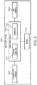
- FIG. 6 depicts an exemplary embodiment of a pump control system 600 suitable for use as the pump control system 520 in FIG. 5 in accordance with one or more embodiments.
- the illustrated pump control system 600 includes, without limitation, a pump control module 602, a communications interface 604, and a data storage element (or memory) 606.
- the pump control module 602 is coupled to the communications interface 604 and the memory 606, and the pump control module 602 is suitably configured to support the operations, tasks, and/or processes described herein.
- the pump control module 602 is also coupled to one or more user interface elements 608 (e.g., user interface 230, 540) for receiving bolus or other delivery instructions and providing notifications or other information to the user.
- FIG. 6 depicts an exemplary embodiment of a pump control system 600 suitable for use as the pump control system 520 in FIG. 5 in accordance with one or more embodiments.
- the illustrated pump control system 600 includes, without limitation, a pump control module 602, a communications interface 604, and a data storage element (or
- FIG. 6 depicts the user interface element 608 as being integrated with the pump control system 600 (e.g., as part of the infusion device 200, 502), in various alternative embodiments, the user interface element 608 may be integrated with the sensing arrangement 504 or another element of an infusion system 100 (e.g., the computer 108 or CCD 106).
- the communications interface 604 generally represents the hardware, circuitry, logic, firmware and/or other components of the pump control system 600 that are coupled to the pump control module 602 and configured to support communications between the pump control system 600 and the sensing arrangement 504.
- the communications interface 604 may include or otherwise be coupled to one or more transceiver modules capable of supporting wireless communications between the pump control system 520, 600 and the sensing arrangement 504 or another electronic device 106, 108 in an infusion system 100.
- the communications interface 604 may be configured to support wired communications to/from the sensing arrangement 504.
- the pump control module 602 generally represents the hardware, circuitry, logic, firmware and/or other component of the pump control system 600 that is coupled to the communications interface 604 and configured to determine dosage commands for operating the motor 507 to deliver fluid to the body 501 based on data received from the sensing arrangement 504 and perform various additional tasks, operations, functions and/or operations described herein.
- pump control module 602 implements or otherwise executes a command generation module 614 that automatically calculates or otherwise determines a dosage command for operating the motor 507 of the infusion device 502 in accordance with a particular operating mode.
- the command generation module 614 supports multiple different operating modes having different delivery control schemes associated therewith.
- command generation module 614 may generate dosage commands for delivering boluses that are manually-initiated or otherwise instructed by a user via a user interface element 608.
- the illustrated pump control module 602 also implements or otherwise executes a diagnostics module 612 that generates or otherwise provides user notifications or alerts via a user interface element 608.
- the pump control module 602 may be implemented or realized with a general purpose processor, a microprocessor, a controller, a microcontroller, a state machine, a content addressable memory, an application specific integrated circuit, a field programmable gate array, any suitable programmable logic device, discrete gate or transistor logic, discrete hardware components, or any combination thereof, designed to perform the functions described herein.
- the steps of a method or algorithm described in connection with the embodiments disclosed herein may be embodied directly in hardware, in firmware, in a software module executed by the pump control module 602, or in any practical combination thereof.
- the pump control module 602 includes or otherwise accesses the data storage element or memory 606, which may be realized using any sort of non-transitory computer-readable medium capable of storing programming instructions for execution by the pump control module 602.
- the computer-executable programming instructions when read and executed by the pump control module 602, cause the pump control module 602 to perform the tasks, operations, functions, and processes described in greater detail below.
- FIG. 6 is a simplified representation of a pump control system 600 for purposes of explanation and is not intended to limit the subject matter described herein in any way.
- the features and/or functionality of the motor control module 512 may be implemented by or otherwise integrated into the pump control system 600 and/or the pump control module 602, for example, by the command generation module 614 converting the dosage command into a corresponding motor command, in which case, the separate motor control module 512 may be absent from an embodiment of the infusion device 502.
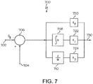
- FIG. 7 depicts an exemplary closed-loop control system 700 that may be implemented by a pump control system 520, 600 to regulate a condition in the body of a user to a desired (or target) value. It should be appreciated that FIG. 7 is a simplified representation of the control system 700 for purposes of explanation and is not intended to limit the subject matter described herein in any way.
- the control system 700 receives or otherwise obtains a target glucose value at input 702.
- the target glucose value may be stored or otherwise maintained by the infusion device 502 (e.g., in memory 606), however, in some alternative embodiments, the target value may be received from an external component (e.g., CCD 106 and/or computer 108).
- the target glucose value may be dynamically calculated or otherwise determined prior to entering the closed-loop operating mode based on one or more patient-specific control parameters.
- the target blood glucose value may be calculated based at least in part on a patient-specific reference basal rate and a patient-specific daily insulin requirement, which are determined based on historical delivery information over a preceding interval of time (e.g., the amount of insulin delivered over the preceding 24 hours).
- the control system 700 also receives or otherwise obtains a current glucose measurement value from the sensing arrangement 504 at input 704.
- the illustrated control system 700 implements or otherwise provides proportional-integral-derivative (PID) control to determine or otherwise generate delivery commands for operating the motor 510 based at least in part on the difference between the target glucose value and the current glucose measurement value.
- PID proportional-integral-derivative
- the PID control attempts to minimize the difference between the measured value and the target value, and thereby regulates the measured value to the desired value.
- PID control parameters are applied to the difference between the target glucose level at input 702 and the measured glucose level at input 704 to generate or otherwise determine a dosage (or delivery) command provided at output 730.
- the motor control module 512 operates the motor 510 to deliver insulin to the body of the user to influence the user's glucose level, and thereby reduce the difference between a subsequently measured glucose level and the target glucose level.
- the illustrated control system 700 includes or otherwise implements a summation block 706 configured to determine a difference between the target value obtained at input 702 and the measured value obtained from the sensing arrangement 504 at input 704, for example, by subtracting the target value from the measured value.
- the output of the summation block 706 represents the difference between the measured and target values, which is then provided to each of a proportional term path, an integral term path, and a derivative term path.
- the proportional term path includes a gain block 720 that multiplies the difference by a proportional gain coefficient, K P , to obtain the proportional term.
- the integral term path includes an integration block 708 that integrates the difference and a gain block 722 that multiplies the integrated difference by an integral gain coefficient, K I , to obtain the integral term.
- the derivative term path includes a derivative block 710 that determines the derivative of the difference and a gain block 724 that multiplies the derivative of the difference by a derivative gain coefficient, K D , to obtain the derivative term.
- the proportional term, the integral term, and the derivative term are then added or otherwise combined to obtain a delivery command that is utilized to operate the motor at output 730.
- Various implementation details pertaining to closed-loop PID control and determine gain coefficients are described in greater detail in United States patent number 7,402,153 , which is incorporated by reference.
- the PID gain coefficients are user-specific (or patient-specific) and dynamically calculated or otherwise determined prior to entering the closed-loop operating mode based on historical insulin delivery information (e.g., amounts and/or timings of previous dosages, historical correction bolus information, or the like), historical sensor measurement values, historical reference blood glucose measurement values, user-reported or user-input events (e.g., meals, exercise, and the like), and the like.
- historical insulin delivery information e.g., amounts and/or timings of previous dosages, historical correction bolus information, or the like
- historical sensor measurement values e.g., blood glucose measurement values
- user-reported or user-input events e.g., meals, exercise, and the like
- one or more patient-specific control parameters may be utilized to compensate, correct, or otherwise adjust the PID gain coefficients to account for various operating conditions experienced and/or exhibited by the infusion device 502.
- the PID gain coefficients may be maintained by the memory 606 accessible to the pump control module 602.
- the memory 606 may include a plurality of registers associated with the control parameters for the PID control.
- a first parameter register may store the target glucose value and be accessed by or otherwise coupled to the summation block 706 at input 702, and similarly, a second parameter register accessed by the proportional gain block 720 may store the proportional gain coefficient, a third parameter register accessed by the integration gain block 722 may store the integration gain coefficient, and a fourth parameter register accessed by the derivative gain block 724 may store the derivative gain coefficient.
- a management system 800 manages transitions between operating modes supported by an infusion device.
- the management system 800 is implemented by a pump control system 520, 600 and/or pump control module 602.
- the various modules 802, 804, 806, 808, 810 may be subcomponents of the pump control module 602 or the command generation module 614.
- the command generation module 614 includes or otherwise implements the management system 800.
- the illustrated system 800 includes a plurality of operating mode control modules 802, 804, 806, 808 along with a supervisory control module 810 that manages transitions between the respective operating modes.
- the supervisory control module 810 operates a command multiplexer 820, which is coupled to the motor control module 512 to output a dosage command from the selected operating mode control module 802, 804, 806, 808 corresponding to the operating mode currently being implemented by the infusion device 502.
- the closed-loop control module 802 generally represents the components of the pump control system 520, 600 that are configured to support the closed-loop operating mode.
- the closed-loop control module 802 may implement the closed-loop control system 700 of FIG. 7 and generate a dosage command based on a difference between the current (or most recent) measurement of the user's interstitial fluid glucose level and a target (or reference) interstitial fluid glucose value.
- the predictive low glucose control module 804 generally represents the components of the pump control system 520, 600 that are configured to support a PLGM operating mode. As described above, the PLGM control module 804 generates dosage commands to provide a basal infusion rate when a predicted glucose value is greater than a predictive suspend threshold and automatically suspends delivery (or generates dosage commands equal to zero) when the predicted glucose value is less than the predictive suspend threshold.
- the low glucose control module 806 generally represents the components of the pump control system 520, 600 that are configured to support a LGS operating mode. As described above, the LGS control module 806 by generates dosage commands to provide a basal infusion rate when the current (or most recent) measurement of the user's interstitial fluid glucose level is greater than a suspend threshold and automatically suspends delivery when the current measurement value is less than the suspend threshold.
- the open-loop control module 808 generally represents the components of the pump control system 520, 600 that are configured to support an open-loop operating mode. In this regard, the open-loop control module 808 generates dosage commands configured to provide a predetermined open-loop basal infusion rate.
- the command multiplexer 820 is coupled to the outputs of the respective control modules 802, 804, 806, 808 to selectively output the dosage command from one of the modules 802, 804, 806, 808 to the motor control module 512 in response to a selection signal from the supervisory control module 810.
- the selection signal identifies the operating mode that is currently being implemented by the infusion device 102, 200, 502.
- the supervisory control module 810 generally represents the components of the pump control system 520, 600 that are coupled to the control modules 802, 804, 806, 808 and configured to support the operating mode transition process 900 and perform the tasks, operations, functions, and processes described herein managing transitions between operating modes associated with the respective control modules 802, 804, 806, 808.
- FIG. 8 is a simplified representation of the management system 800 for purposes of explanation and is not intended to limit the subject matter described herein in any way.
- any number of operating mode control modules may be present to support any number of operating modes.
- the features and/or functionality of the command multiplexer 820 may be implemented by or otherwise integrated into the supervisory control module 810.
- the features and/or functionality of the management system 800 are implemented by control electronics 224 located in the fluid infusion device 200, 502
- various aspects of the management system 800 may be implemented by a remote computing device that is physically distinct and/or separate from the infusion device 200, 502, such as, for example, the CCD 106 or the computing device 108.
- FIG. 9 depicts an exemplary operating mode transition process 900 suitable for implementation by a control system associated with a fluid infusion device to manage transitions between operating modes supported by the device.
- Various tasks performed in connection with the operating mode transition process 900 may be performed by hardware, firmware, software executed by processing circuitry, or any combination thereof.
- the following description refers to elements mentioned above in connection with FIGS. 1-7 .
- portions of the operating mode transition process 900 may be performed by different elements of the control system 500, such as, for example, the infusion device 502, the pump control system 520, 600, the diagnostics module 612, the command generation module 614, the management system 800, the supervisory control module 810 and/or the command multiplexer 820.
- the operating mode transition process 900 may include any number of additional or alternative tasks, the tasks need not be performed in the illustrated order and/or the tasks may be performed concurrently, and/or the operating mode transition process 900 may be incorporated into a more comprehensive procedure or process having additional functionality not described in detail herein. Moreover, one or more of the tasks shown and described in the context of FIG. 9 could be omitted from a practical embodiment of the operating mode transition process 900 as long as the intended overall functionality remains intact.
- the operating mode transition process 900 initializes or otherwise begins in response to detecting or otherwise identifying a desire to exit a particular operating mode.
- the operating mode transition process 900 may be initiated in response to a user manipulating the user interface 540, 608 to indicate a desire to exit one operating mode and enter another operating mode.
- the operating mode transition process 900 may be initiated in response to a particular operating mode automatically determining it should be exited and providing a corresponding indication to the supervisory module 810.
- a maximum time limit may be imposed for one or more of the control modules 802, 804, 806, 808, with the respective control module 802, 804, 806, 808 implementing a timer and automatically notifying the supervisory control module 810 when the maximum time limit has been reached.
- the supervisory control module 810 may implement the appropriate timers and identify when the maximum time limit for a particular operating mode has been reached.
- one or more of the control modules 802, 804, 806, 808 may be configured to continually monitor or analyze its performance and detect or otherwise identify that its operating mode should be terminated when its performance appears to be unreliable.
- the closed-loop control module 802 may automatically identify that the closed-loop operating mode should exit when one or more of the closed-loop control parameters appears to be invalid or unreliable, when measurement values from the sensing arrangement 504 appear to be invalid or unreliable, or the like.
- the operating mode transition process 900 receives or otherwise obtains operational information pertaining to the operating mode being exited along with clinical information pertaining to the physiological condition of the user (tasks 902, 904).
- the supervisory module 810 obtains operational information from the control module 802, 804, 806, 808 associated with the operating mode currently being implemented.
- the operational information includes timer values (e.g., a delivery suspend time, a refractory period time, and the like), delivery status (e.g., whether or not delivery has been suspended), alert or event information (e.g., hypoglycemic events or alerts, hyperglycemic events or alerts, and the like), the reason the operating mode is terminating (e.g., manually-initiated, timeout, invalid control parameters and/or invalid measurement values, an anomalous condition, or the like), and other information characterizing the current instance of the operating mode.
- the supervisory module 810 obtains clinical information for the user, such as, for example, recent sensor glucose measurement values, predicted glucose measurement values, blood glucose reference measurement values, sensor calibration data, other historical data, and the like, from memory 606.
- the mode transition process 900 identifies or otherwise determines the available operating modes for the transition destination (task 906).
- the supervisory module 810 utilizes the clinical information in conjunction with the operational information to identify which other operating modes are viable destinations for the transition while excluding any operating modes that are likely to violate one or more applicable constraints or otherwise are not likely to be viable.
- the mode transition process 900 increases the likelihood that the destination operating mode will not result in violations of applicable delivery control rules, constraints, limits, or the like.
- the mode transition process 900 also reduces the likelihood that the destination operating mode will generate alerts that could degrade the user experience, and reduces the likelihood that the destination operating mode will automatically terminate or exit after being activated.
- a maximum suspension time limit may be imposed on the infusion device 502 across all operating modes, with the supervisory module 810 excluding operating modes that would likely result in the minimum suspension time being violated based on the current suspend duration for the initial operating mode and the current or predicted glucose values for the user. For example, if transitioning from a closed-loop operating mode that has been suspending delivery for a period of time, and the user's predicted glucose value indicates the PLGM operating mode will likely suspend delivery for an additional amount of time such that the sum of the current suspend duration for the closed-loop operating mode and the expected suspend duration for the PLGM operating mode exceeds the maximum suspension time, the supervisory module 8 10 may exclude the PLGM operating mode from consideration as a possible destination operating mode.
- a maximum insulin delivery limit over a particular timeframe may be imposed, with the supervisory module 810 excluding operating modes that would likely result in the maximum insulin delivery limit being delivered based on the amount of insulin delivered for the initial operating mode and the current or predicted glucose values for the user. For example, if the difference between current and/or predicted glucose values for the user and the target glucose value for the closed-loop operating mode indicates that the closed-loop operating mode is likely to result in an amount of fluid delivery that would cause a maximum insulin delivery limit to be violated, the supervisory module 810 may exclude the closed-loop operating mode from consideration as a possible destination operating mode.
- a safe basal delivery mode (or hybrid closed-loop delivery mode) may be identified as a possible destination operating mode.
- the safe basal delivery mode may be realized as a hybrid closed-loop operating mode that configured to maintain a delivery rate that does not violate either the maximum insulin delivery limit or a minimum insulin delivery limit independent of the current or predicted measurements of the user's glucose.
- the safe basal delivery mode may impose a maximum delivery rate that is less than or equal to the maximum insulin delivery limit divided by its applicable timeframe and impose a minimum delivery rate that is greater than the minimum insulin delivery limit divided by its applicable timeframe.
- the delivery commands generated in the safe basal delivery mode based on the difference between the current sensor glucose measurement value and the target glucose measurement value are bounded such that they will not violate applicable delivery limits.
- the supervisory module 810 may exclude operating modes that would likely result in the minimum insulin delivery limit being violated based on the amount of insulin delivered for the initial operating mode and the current or predicted glucose values for the user. For example, if the difference between current and/or predicted glucose values for the user and the target glucose value indicates the closed-loop operating mode is unlikely to deliver fluid for an amount of time that would cause the minimum insulin delivery limit to be violated, the supervisory module 810 may exclude the closed-loop operating mode from consideration as a possible destination operating mode. In some embodiments, if the mode transition process 900 is initiated in response to the minimum insulin delivery limit being reached during implementation of a current operating mode, a safe basal delivery mode may be identified as a possible destination operating mode in lieu of the closed-loop operating mode.
- the supervisory module 810 may exclude operating modes that utilize sensor glucose measurement values based on sensor health information.
- recent sensor glucose measurement values or historical calibration information for the sensing arrangement 504 indicating that the sensing arrangement 504 may not be viable for the particular operating mode.
- the supervisory module 810 prevents entry of operating modes that would otherwise be relying potentially unreliable sensor measurement values.
- the supervisory module 810 may exclude the closed-loop operating mode from consideration as a possible destination operating mode if a difference between the current sensor glucose measurement value and a predicted glucose value is greater than a threshold value, a calibration factor for the sensing arrangement 504 has expired, communications with the sensing arrangement 504 have been interrupted, a difference between the current calibration factor and the preceding calibration factor is greater than a threshold amount (e.g., a difference of more than 35%), or a difference between reference blood glucose measurement value and the corresponding sensor measurement value used for the current calibration factor is greater than a threshold amount (e.g., the sensor measurement value is more than 35% greater than or less than the reference blood glucose measurement value).
- a threshold amount e.g., a difference of more than 35%
- a difference between reference blood glucose measurement value and the corresponding sensor measurement value used for the current calibration factor is greater than a threshold amount (e.g., the sensor measurement value is more than 35% greater than or less than the reference blood glucose measurement value).
- a desired maximum number of alerts over a particular timeframe could be designated by the user, with the supervisory module 810 excluding operating modes that would likely result in that maximum number of alerts being exceeded.
- the operational information obtained by the supervisory module 810 may include a current number of user notifications or alerts that have been generated by the current operating mode (e.g., by the respective control module 802, 804, 806, 808 implementing a corresponding counter).
- the supervisory module 810 may determine an expected number of user notifications or alerts to be generated by a particular operating mode based on the current and/or predicted glucose values for the user, and exclude that operating mode from the set of possible destination operating modes when the sum of the expected number of alerts and the current number of alerts exceeds the maximum number chosen by the user.
- the supervisory module 810 excludes operating modes based on the status of user notifications previously generated by the infusion device 502. For example, if a user notification has been generated that indicates the user should recalibrate or replace the sensing arrangement 504, and the user has not responded to the user notification by recalibrating or replacing the sensing arrangement 504 within a threshold amount of time (e.g., 90 minutes), the supervisory module 810 may exclude the closed-loop operating mode or other operating modes that rely on the sensing arrangement 504 from consideration as possible destination modes until the user responds to the notification.
- a threshold amount of time e.g. 90 minutes
- the mode transition process 900 continues by identifying or otherwise selecting a destination operating mode from among the group of available operating modes (task 908).
- the supervisory module 810 automatically selects the available operating mode to that is most preferable or most highly ranked based on device settings or user preferences maintained in memory 606.
- the user may manipulate a user interface 540, 608 to establish a hierarchical ordering of the operating modes in the user's order of preference, with the hierarchical information being stored in the memory 606 along with other user preferences.
- the user may identify the closed-loop operating mode as the most preferred operating mode, followed by the PLGM operating mode as the next most preferred operating mode, the LGS operating mode as the next most preferred operating mode, and the open-loop operating mode as the least preferred operating mode.
- default settings for the infusion device 102, 200, 502 may specify a default hierarchical order of operating modes. It should be appreciated, however, that the subject matter described herein is not limited to any particular type of selection criteria used to identify the most preferable operating mode from among the available operating modes.
- the mode transition process 900 continues by identifying or otherwise determining the types or subset of operational information pertaining to the current operating mode to be provided to the destination operating mode and providing that identified operational information to the destination operating mode (tasks 910, 912).
- the supervisory module 810 passes at least a portion of the operational information obtained from the current operating mode control module 802, 804, 806, 808 to the destination module 802, 804, 806, 808 such that the implementation of the destination operating mode does not violate any delivery rules, constraints, limits, or the like.
- the supervisory module 810 may obtain the current refractory period timer value, the current suspend duration timer value, or the like, from the control module 802, 804, 806, 808 corresponding to the current operating mode and provide those values to the control module 802, 804, 806, 808 corresponding to the destination operating mode to ensure that the destination operating mode does not violate a minimum refractory time period between suspending delivery, a maximum suspend duration, a minimum suspend duration, or the like. Additionally, the supervisory module 810 may provide the exit reason for the current operating mode, the current delivery status, information about alerts or events that occurred during the current operating mode, active insulin estimates, sensor health status and/or calibration information, and/or other historical delivery information to the destination operating mode control module 802, 804, 806, 808. The destination operating mode generates dosage commands in accordance with the operational information received from the preceding operating mode to provide a relatively seamless transition among operating modes.
- the mode transition process 900 continues by providing, to the infusion device motor control module, the dosage (or delivery) commands generated by the destination operating mode in accordance with the provided operational information (task 914).
- the supervisory module 810 signals, commands or otherwise operates the command multiplexer 820 to output dosage commands generated by the destination operating mode control module 802, 804, 806, 808 and cease outputting dosage commands from the previously-active operating mode.
- the supervisory module 810 signals, commands or otherwise operates the command multiplexer 820 to output dosage commands generated by the PLGM control module 804 instead of the closed-loop control module 802.
- the supervisory module 810 may assert or otherwise provide interrupt signals that indicate, to the respective control modules 802, 804, 806, 808, whether or not the respective control module 802, 804, 806, 808 should generate dosage commands.
- the supervisory module 810 may deactivate the closed-loop control module 802 (e.g., by providing a logical high interrupt signal to the closed-loop control module 802) and activate the PLGM control module 804 (e.g., by providing a logical low interrupt signal to the PLGM control module 804) while maintaining the other control modules 806, 808 deactivated.
- the supervisory module 810 when transitioning from the closed-loop operating mode to the PLGM operating mode, the supervisory module 810 obtains information identifying the exit reason (e.g., manual or auto), the amount of time delivery has been suspended in the preceding sixty minutes, and the current value of the closed-loop refractory timer from the closed-loop control module 802. In some embodiments, the supervisory module 810 calculates the refractory time based on the amount of continuous delivery commands that precede the transition. The supervisory module 810 provides the obtained values and information to the PLGM control module 804, and thereafter, the PLGM control module 804 generates dosage commands in accordance with the operational information from the closed-loop control module 802.
- the exit reason e.g., manual or auto
- the supervisory module 810 calculates the refractory time based on the amount of continuous delivery commands that precede the transition.
- the supervisory module 810 provides the obtained values and information to the PLGM control module 804, and thereafter, the PLGM control module 804
- the PLGM control module 804 may set its refractory timer to the value of the closed-loop refractory timer and maintain delivery until the total refractory time exceeds the minimum refractory time period before suspending delivery. Thus, even if the user's predicted glucose level is below the predictive suspend threshold, the PLGM control module 804 may continue providing dosage commands that result in a basal rate of infusion until the value of the PLGM refractory timer is greater than or equal to the minimum refractory time period. In some embodiments, the PLGM control module 804 may utilize the exit reason to determine whether to continue providing dosage commands until the value of the PLGM refractory timer is greater than or equal to the minimum refractory time period.
- the PLGM control module 804 may provide dosage commands until the minimum refractory time period is observed, however, if the exit reason is automatic, the PLGM control module 804 may suspend dosage commands before the minimum refractory time period is observed and reset the PLGM refractory timer as appropriate.
- the sensor health status and/or calibration information, estimated active insulin information, and/or other operational information from the closed-loop operating mode may be utilized in conjunction with the exit reason when determining whether to observe the minimum refractory time period in the PLGM operating mode.
- the PLGM control module 804 may allow dosage commands to be suspended only if the sensing arrangement 504 was calibrated less than a threshold amount of time before the transition (e.g., within the last hour) and the estimated active insulin is greater than a safe threshold value, which may be manually set by a user or a default value maintained by the infusion device 502.
- the minimum refractory time period may still be observed for an automatic transition if the sensing arrangement 504 was not calibrated recently or the estimated active insulin is too low.
- the PLGM control module 804 may automatically suspend delivery when the refractory time from the closed-loop control module 802 is less than the minimum refractory time period in response to determining the active insulin estimate from the closed-loop control module 802 is greater than the threshold value.
- the PLGM control module 804 may set its delivery suspend timer to the value of the closed-loop suspend timer (e.g., the amount of time delivery has been suspended in the preceding sixty minutes). Thus, even if the user's predicted glucose level is below the predictive suspend threshold, the PLGM control module 804 may begin providing dosage commands once the value of the PLGM delivery suspend timer is greater than the maximum suspension time period. Additionally, in some embodiments, the exit reason may be utilized by the PLGM control module 804 to determine whether to suspend delivery or resume delivery, either independently or in conjunction with the sensor health status and/or calibration information, estimated active insulin information, and/or other operational information, in a similar manner as described above.
- the exit reason may be utilized by the PLGM control module 804 to determine whether to suspend delivery or resume delivery, either independently or in conjunction with the sensor health status and/or calibration information, estimated active insulin information, and/or other operational information, in a similar manner as described above.
- the PLGM control module 804 may resume providing dosage commands even though the maximum suspension time period may not have been met.
- the supervisory module 810 When transitioning from the closed-loop operating mode to the LGS operating mode, the supervisory module 810 obtains information identifying the exit reason (e.g., manual or auto), the amount of time delivery has been suspended in the preceding sixty minutes, and the current value of the closed-loop refractory timer from the closed-loop control module 802 and provides the obtained values and information to the LGS control module 806 for generating dosage commands in accordance therewith, in a similar manner as described above for transitions to the PLGM operating mode.
- the exit reason e.g., manual or auto
- the supervisory module 810 may only provide the refractory timer values from the closed-loop control module 802 to the open-loop control module 808.
- the open-loop control module 808 provides dosage commands that result in an open-loop basal rate of infusion while dynamically updating the refractory timer value for a subsequent transition to another operating mode.
- the refractory timer value is updated so that if the infusion device 502 subsequently transitions from the open-loop operating mode to another operating mode where delivery could be suspended, the minimum refractory period is still observed by the control module 802, 804, 806 associated with that subsequent operating mode before delivery is suspended.
- the supervisory module 810 may independently manage and dynamically update the refractory time information, and subsequently provide the refractory time information to another destination control module 802, 804, 806 when transitioning from the open-loop operating mode.
- the supervisory module 810 may provide suspension information to the open-loop control module 808 (e.g., the amount of time delivery was suspended over a preceding time interval) for dynamically updating the suspension time information to ensure any maximum suspension limits are still observed by a control module 802, 804, 806 associated with that subsequent operating mode.
- the supervisory module 810 may also independently manage and dynamically update the refractory time information, and subsequently provide the refractory time information to a destination control module 802, 804, 806 when transitioning from the open-loop operating mode.
- the supervisory module 810 when transitioning from the PLGM operating mode or the LGS operating mode to the closed-loop operating mode, the supervisory module 810 obtains information identifying the exit reason (e.g., manual or auto) and the current value of the respective refractory timer from the respective control module 804, 806 and provides the obtained values and information to the closed-loop control module 802.
- the closed-loop control module 802 sets its refractory timer to the value of the refractory timer of the respective control module 804, 806 and may maintain delivery until the total refractory time exceeds the minimum refractory time period before suspending delivery.
- the closed-loop control module 802 may suspend delivery even though the total refractory time is less than the minimum refractory time period. For example, the closed-loop control module 802 may obtain sensor calibration information from the preceding operating mode and determine whether a duration of time that has elapsed since the most recent calibration exceeds a threshold value corresponding to the reliable lifetime of a calibration factor for purposes of the closed-loop mode. When the duration of time that has elapsed since the most recent calibration exceeds the threshold value, the closed-loop control module 802 may generate a notification via the user interface 540 that prompts the user to obtain a new blood glucose reference measurement value for recalibrating the sensing arrangement 504 upon transitioning to the closed-loop mode.
- the closed-loop control module 802 may suspend delivery even though the total refractory time does not exceed the minimum refractory time period. Alternatively, in the absence of a new blood glucose reference measurement value that indicates delivery should be suspended, the closed-loop control module 802 may generate dosage commands to provide a minimum basal rate of infusion while the closed-loop refractory timer value is less than the minimum refractory time period even though the user's current glucoses measurement value may be less than the target glucose value for the closed-loop control system.
- the supervisory module 810 when transitioning from the open-loop operating mode to another operating mode, the supervisory module 810 obtains information identifying the exit reason (e.g., manual or auto) and the current value of the refractory timer from the open-loop module 808 and provides the obtained value to the particular destination operating mode control module 802, 804, 806.
- the destination operating mode control module 802, 804, 806 sets its refractory timer to the value provided by the supervisory module 810 to maintain delivery until the total refractory time exceeds the minimum refractory time period before allowing delivery to be suspended.
- control modules 802, 804, 806, 808 may exchanged among control modules 802, 804, 806, 808 to achieve a desired manner of transitioning and comply with the particular constraints, rules, and/or limits for a particular application. Accordingly, the above examples are provided merely to aid in understanding of the subject matter and are not intended to be limiting.
- the subject matter described herein facilitates transitioning between operating modes in a manner that enhances the user experience (e.g., by enabling the user to proactively increase viability of a desired operating mode and/or excluding operating modes that are likely to generate alerts from possible destinations for automatic transitions) and ensures compliance with applicable delivery control rules and other constraints (e.g., by excluding operating modes that are otherwise likely to result in a violation and transferring timer and/or counter values across operating modes).
Abstract
Description
- This PCT application claims the benefit of, and claims priority to: United States Patent Application Serial Number
14/561,133, filed December 4, 2014 - Embodiments of the subject matter described herein relate generally to medical devices, and more particularly, embodiments of the subject matter relate to managing transitions into fluid infusion device operating modes.
- Infusion pump devices and systems are relatively well known in the medical arts, for use in delivering or dispensing an agent, such as insulin or another prescribed medication, to a patient. A typical infusion pump includes a pump drive system which typically includes a small motor and drive train components that convert rotational motor motion to a translational displacement of a plunger (or stopper) in a reservoir that delivers medication from the reservoir to the body of a user via a fluid path created between the reservoir and the body of a user. Use of infusion pump therapy has been increasing, especially for delivering insulin for diabetics.
- Continuous insulin infusion provides greater control of a diabetic's condition, and hence, control schemes are being developed that allow insulin infusion pumps to monitor and regulate a user's blood glucose level in a substantially continuous and autonomous manner. For example, an insulin infusion pump may operate in a closed-loop operating mode overnight while a user is sleeping to regulate the user's glucose level to a target glucose level. In practice, multiple different operating modes for providing continuous insulin infusion may be supported by an infusion pump. However, care must be taken when transitioning between operating modes to avoid potentially compromising a user's condition and ensure compliance with applicable regulatory requirements.
- Additionally, in some situations, one or more preconditions must be satisfied before entering to a particular operating mode is allowed. When preconditions are not satisfied, entry into the operating mode may be denied, which may frustrate a user who would like to operate the infusion pump in that particular operating mode at that particular moment in time. Additionally, after entering a particular operating mode, various conditions may be encountered while operating the infusion pump in that operating mode that result in generation of alerts, which could be disruptive or distracting to the user. Thus, it is desirable to provide multiple different operating modes that facilitate greater and more customizable control over the user's physiological condition without degrading the user experience.
- Infusion devices, systems and related methods of operation in accordance with various operating modes are provided. One exemplary method involves operating an infusion device to deliver fluid to a user in accordance with a first operating mode of a plurality of operating modes, obtaining operational information pertaining to the first operating mode, and obtaining clinical information pertaining to the user. The method continues by determining a destination operating mode of the plurality of operating modes based at least in part on the operational information and the clinical information, and operating the infusion device to deliver the fluid in accordance with the destination operating mode in a manner that is influenced by at least a portion of the operational information pertaining to the first operating mode.
- Another embodiment of an infusion device includes a data storage element to maintain operational information pertaining to a first operating mode of a plurality of operating modes and clinical information pertaining to a user, a motor operable to deliver fluid influencing a physiological condition to a body of the user, and a control system coupled to the motor and the data storage element. The control system operates the motor to deliver the fluid in accordance with the first operating mode, determines a destination operating mode of the plurality of operating modes based at least in part on the operational information and the clinical information, and operates the infusion device to deliver the fluid in accordance with the destination operating mode in a manner that is influenced by at least a portion of the operational information pertaining to the first operating mode.
- In yet another embodiment, a method of operating an infusion device operable to deliver insulin to a user involves operating the infusion device to deliver the insulin in accordance with a first operating mode of a plurality of operating modes, obtaining operational information pertaining to the first operating mode, and obtaining one or more glucose values for the user. In response to an indication to terminate the first operating mode, the method continues by determining a set of one or more possible operating modes from the plurality of operating modes based at least in part on the one or more glucose values and the operational information. The method selects a destination operating mode from the set of one or more possible operating modes and operates the infusion device to deliver the insulin in accordance with the destination operating mode in a manner that is influenced by at least a portion of the operational information pertaining to the first operating mode.
- The invention also provides an infusion device for a medicinal fluid, the device including: a motor operable to deliver the fluid in response to commands; a management system coupled to the motor for generating said commands; wherein the management system includes: a plurality of control modules each configured to generate said commands in accordance with a different respective operating mode; a supervisory module connected to each of the control modules and configured to monitor the status of the control modules, and to receive a mode transition signal; a command multiplexer connected to each of the control modules, to the motor, and to the supervisory module and configured to direct the said commands from a selected one of the control modules to the motor, in accordance with a selection signal from the supervisory module; the supervisory module being further configured to change the selection signal, upon receipt of the mode transition signal thereby causing the command multiplexer to direct the commands from a different selected one of the control modules to the motor.
- The infusion device may further include a user interface and the mode transition signal may be generated by a user manipulating the user interface. The management system may be configured to generate the mode transition signal in response to a predetermined maximum operation time limit being reached by a control module that is generating the commands being sent to the motor. In addition, or instead, the management system may be configured to generate the mode transition signal in response to a unreliability being detected in a control module that is generating the commands being sent to the motor. The supervisory module maybe configured to inhibit the selection on receipt of the mode transition signal, of a control module in which an unreliability has been detected.
- The said status may include a prediction of future commands that would be directed to the motor if a respective control module were selected, and the supervisory module may be configured to inhibit the selection on receipt of the mode transition signal, of a control module where the future commands would result in one or more of transgression of a pre-specified maximum suspension time, transgression of a pre-specified maximum delivery limit, and failure to meet a pre-specified minimum delivery threshold.
- The operating modes may be selected from a list comprising open-loop mode, closed-loop mode, LGS mode in which a basal rate of delivery of the medicinal fluid is provided while a physiological analyte level that is controlled by the medicinal fluid is above a threshold and suspended while it is not, and PLGM mode in which a basal rate of delivery of the medicinal fluid is provided while a predicted level of the physiological analyte that is controlled by the medicinal fluid is above a threshold and suspended while it is not. The medicinal fluid may be insulin.
- This summary is provided to introduce a selection of concepts in a simplified form that are further described below in the detailed description. This summary is not intended to identify key features or essential features of the claimed subject matter, nor is it intended to be used as an aid in determining the scope of the claimed subject matter.
- A more complete understanding of the subject matter may be derived by referring to the detailed description and claims when considered in conjunction with the following figures, wherein like reference numbers refer to similar elements throughout the figures, which may be illustrated for simplicity and clarity and are not necessarily drawn to scale.
-
FIG. 1 depicts an exemplary embodiment of an infusion system; -
FIG. 2 depicts a plan view of an exemplary embodiment of a fluid infusion device suitable for use in the infusion system ofFIG. 1 ; -
FIG. 3 is an exploded perspective view of the fluid infusion device ofFIG. 2 ; -
FIG. 4 is a cross-sectional view of the fluid infusion device ofFIGS. 2-3 as viewed along line 4-4 inFIG. 3 when assembled with a reservoir inserted in the infusion device; -
FIG. 5 is a block diagram of an exemplary control system suitable for use in a fluid infusion device, such as the fluid infusion device ofFIG. 1 orFIG. 2 ; -
FIG. 6 is a block diagram of an exemplary pump control system suitable for use in the control system ofFIG. 5 ; -
FIG. 7 is a block diagram of a closed-loop control system that may be implemented or otherwise supported by the pump control system in the fluid infusion device ofFIG. 5 in one or more exemplary embodiments; -
FIG. 8 is a block diagram of an exemplary management system that may be implemented or otherwise supported by the pump control system in the fluid infusion device ofFIG. 5 in one or more exemplary embodiments; and -
FIG. 9 is a flow diagram of an exemplary operating mode transition process suitable for use with the control system ofFIG. 5 . - The following detailed description is merely illustrative in nature and is not intended to limit the embodiments of the subject matter or the application and uses of such embodiments. As used herein, the word "exemplary" means "serving as an example, instance, or illustration." Any implementation described herein as exemplary is not necessarily to be construed as preferred or advantageous over other implementations. Furthermore, there is no intention to be bound by any expressed or implied theory presented in the preceding technical field, background, brief summary or the following detailed description.
- While the subject matter described herein can be implemented in any electronic device that includes a motor, exemplary embodiments described below are implemented in the form of medical devices, such as portable electronic medical devices. Although many different applications are possible, the following description focuses on a fluid infusion device (or infusion pump) as part of an infusion system deployment. For the sake of brevity, conventional techniques related to infusion system operation, insulin pump and/or infusion set operation, and other functional aspects of the systems (and the individual operating components of the systems) may not be described in detail here. Examples of infusion pumps may be of the type described in, but not limited to, United States Patent numbers:
4,562,751 ;4,685,903 ;5,080,653 ;5,505,709 ;5,097,122 ;6,485,465 ;6,554,798 ;6,558,320 ;6,558,351 ;6,641,533 ;6,659,980 ;6,752,787 ;6,817,990 ;6,932,584 ; and7,621,893 ; each of which are herein incorporated by reference. - Described herein is a fluid infusion devices including a motor that is operable to linearly displace a plunger (or stopper) of a reservoir provided within the fluid infusion device to deliver a dosage of fluid, such as insulin, to the body of a user. However, as the invention relates to the operation of the infusion device and the structure necessary for that operation detail of any mechanical structures for conveying or propelling the fluid is given as an example only. Dosage commands that govern operation of the motor, i.e. the device responsible for directly or indirectly imparting motion to the fluid, may be generated in an automated manner in accordance with the delivery control scheme associated with a particular operating mode. The fluid infusion device may be operated in any one of a number of operating modes and be able to switch between the modes. Examples of operating modes are closed-loop, predictive, and open-loop. The device typically contains algorithms which when executed implement respective ones of the operating modes. In that case switching modes involves switching from one algorithm to another. In a closed-loop operating mode, for example, the dosage commands are generated based on a difference between a current (or most recent) measurement of a physiological condition in the body of the user (e.g., an interstitial fluid glucose level in the case of diabetes management by infusion of insulin) and a target (or reference) value for that physiological condition. In a predictive operating mode, the dosage commands may be influenced by a predicted value (or anticipated measurement) for that physiological condition in the body of the user at some point in the future. Conversely, in an open-loop operating mode, the dosage commands may be configured to implement a predetermined delivery rate. Such rate may be substantially independent of the current or predicted measurements of the physiological condition of the user.
- As described in greater detail below primarily in the context of
FIGS. 8-9 , in exemplary embodiments, transitions between operating modes implemented by the infusion device are also supervised or otherwise managed to maintain satisfactory control of the user's physiological condition and ensure compliance with applicable delivery control rules. The delivery control rules may be dictated by regulatory requirements, manufacturer requirements, device settings, user preferences, or the like. In this regard, the destination operating mode is initialized using operational information pertaining to the current operation of the infusion device in the initial operating mode being transitioned from to provide a relatively seamless transition between operating modes. In exemplary embodiments, before transitioning to the destination operating mode, information pertaining to the operating mode currently being implemented is obtained. The operational information characterizes the current instance of the current operating mode and may include, for example, delivery or suspension information (e.g., whether or not delivery was suspended at any time, the duration delivery was suspended, and the like), the values of any active timers (e.g., the duration of a current instance of delivery suspension, the duration of a current refractory period, and the like), alert information (e.g., whether or not any alerts where generated, and information identifying what types of alerts were generated or the root cause) and information indicating why the current instance of the current operating mode is being exited. At least a portion of the operational information is provided to the destination operating mode upon the transition from the previous operating mode, with the operation of the infusion device in accordance with the destination operating mode being influenced by that operational information. For example, the destination operating mode may be initialized with the same timer values or counter values from the preceding operating mode to ensure that no time constraints or other applicable maximum limits are violated by the destination operating mode. - In exemplary embodiments, before transitioning into a destination operating mode, clinical status information pertaining to the physiological condition of the user is also obtained. As described above, the clinical information may include, for example, recent or historical sensor measurement values of the physiological condition of the user, reference measurement values of the physiological condition of the user, sensor calibration history for the user, and the like. In one or more embodiments, the destination operating mode is automatically determined based at least in part on portions of the clinical information and the operational information for the current operating mode along with the device settings or user preferences establishing a hierarchical order for the operating modes. In this regard, the clinical information and/or the operational information may be used to identify and exclude operating modes that are likely to violate any applicable constraints or requirements upon entry, with the hierarchical information for the operating modes being used to select the most preferable operating mode from among the remaining potential operating modes.
- Turning now to
FIG. 1 , one exemplary embodiment of aninfusion system 100 includes, without limitation, a fluid infusion device (or infusion pump) 102, asensing arrangement 104, a command control device (CCD) 106, and acomputer 108. The components of aninfusion system 100 may be realized using different platforms, designs, and configurations, and the embodiment shown inFIG. 1 is not exhaustive or limiting. In practice, theinfusion device 102 and thesensing arrangement 104 are secured at desired locations on the body of a user (or patient), as illustrated inFIG. 1 . In this regard, the locations at which theinfusion device 102 and thesensing arrangement 104 are secured to the body of the user inFIG. 1 are provided only as a representative, non-limiting, example. The elements of theinfusion system 100 may be similar to those described in United States Patent No.8,674,288 , the subject matter of which is hereby incorporated by reference in its entirety. - In the illustrated embodiment of
FIG. 1 , theinfusion device 102 is designed as a portable medical device suitable for infusing a fluid, a liquid, a gel, or other agent into the body of a user. In exemplary embodiments, the infused fluid is insulin, although many other fluids may be administered through infusion such as, but not limited to, HIV drugs, drugs to treat pulmonary hypertension, iron chelation drugs, pain medications, anti-cancer treatments, medications, vitamins, hormones, or the like. In some embodiments, the fluid may include a nutritional supplement, a dye, a tracing medium, a saline medium, a hydration medium, or the like. - The
sensing arrangement 104 generally represents the components of theinfusion system 100 configured to sense, detect, measure or otherwise quantify a condition of the user, and may include a sensor, a monitor, or the like, for providing data indicative of the condition that is sensed, detected, measured or otherwise monitored by the sensing arrangement. In this regard, thesensing arrangement 104 may include electronics and enzymes reactive to a biological condition, such as a blood glucose level, or the like, of the user, and provide data indicative of the blood glucose level to theinfusion device 102, theCCD 106 and/or thecomputer 108. For example, theinfusion device 102, theCCD 106 and/or thecomputer 108 may include a display for presenting information or data to the user based on the sensor data received from thesensing arrangement 104, such as, for example, a current glucose level of the user, a graph or chart of the user's glucose level versus time, device status indicators, alert messages, or the like. In other embodiments, theinfusion device 102, theCCD 106 and/or thecomputer 108 may include electronics and software that are configured to analyze sensor data and operate theinfusion device 102 to deliver fluid to the body of the user based on the sensor data and/or preprogrammed delivery routines. Thus, in exemplary embodiments, one or more of theinfusion device 102, thesensing arrangement 104, theCCD 106, and/or thecomputer 108 includes a transmitter, a receiver, and/or other transceiver electronics that allow for communication with other components of theinfusion system 100, so that thesensing arrangement 104 may transmit sensor data or monitor data to one or more of theinfusion device 102, theCCD 106 and/or thecomputer 108. - Still referring to
FIG. 1 , in various embodiments, thesensing arrangement 104 may be secured to the body of the user or embedded in the body of the user at a location that is remote from the location at which theinfusion device 102 is secured to the body of the user. In various other embodiments, thesensing arrangement 104 may be incorporated within theinfusion device 102. In other embodiments, thesensing arrangement 104 may be separate and apart from theinfusion device 102, and may be, for example, part of theCCD 106. In such embodiments, thesensing arrangement 104 may be configured to receive a biological sample, analyte, or the like, to measure a condition of the user. - As described above, in some embodiments, the
CCD 106 and/or thecomputer 108 may include electronics and other components configured to perform processing, delivery routine storage, and to control theinfusion device 102 in a manner that is influenced by sensor data measured by and/or received from thesensing arrangement 104. By including control functions in theCCD 106 and/or thecomputer 108, theinfusion device 102 may be made with more simplified electronics. However, in other embodiments, theinfusion device 102 may include all control functions, and may operate without theCCD 106 and/or thecomputer 108. In various embodiments, theCCD 106 may be a portable electronic device. In addition, in various embodiments, theinfusion device 102 and/or thesensing arrangement 104 may be configured to transmit data to theCCD 106 and/or thecomputer 108 for display or processing of the data by theCCD 106 and/or thecomputer 108. - In some embodiments, the
CCD 106 and/or thecomputer 108 may provide information to the user that facilitates the user's subsequent use of theinfusion device 102. For example, theCCD 106 may provide information to the user to allow the user to determine the rate or dose of medication to be administered into the user's body. In other embodiments, theCCD 106 may provide information to theinfusion device 102 to autonomously control the rate or dose of medication administered into the body of the user. In some embodiments, thesensing arrangement 104 may be integrated into theCCD 106. Such embodiments may allow the user to monitor a condition by providing, for example, a sample of his or her blood to thesensing arrangement 104 to assess his or her condition. In some embodiments, thesensing arrangement 104 and theCCD 106 may be used for determining glucose levels in the blood and/or body fluids of the user without the use of, or necessity of, a wire or cable connection between theinfusion device 102 and thesensing arrangement 104 and/or theCCD 106. - In some embodiments, the
sensing arrangement 104 and/or theinfusion device 102 are cooperatively configured to utilize a closed-loop system for delivering fluid to the user. Examples of sensing devices and/or infusion pumps utilizing closed-loop systems may be found at, but are not limited to, the following United States patent numbers:6,088,608 ,6,119,028 ,6,589,229 ,6,740,072 ,6,827,702 ,7,323,142 , and7,402, 153 , all of which are incorporated herein by reference in their entirety. In such embodiments, thesensing arrangement 104 is configured to sense or measure a condition of the user, such as, blood glucose level or the like. Theinfusion device 102 is configured to deliver fluid in response to the condition sensed by thesensing arrangement 104. In turn, thesensing arrangement 104 continues to sense or otherwise quantify a current condition of the user, thereby allowing theinfusion device 102 to deliver fluid continuously in response to the condition currently (or most recently) sensed by thesensing arrangement 104 indefinitely. In some embodiments, thesensing arrangement 104 and/or theinfusion device 102 may be configured to utilize the closed-loop system only for a portion of the day, for example only when the user is asleep or awake. -
FIGS. 2-4 depict one exemplary embodiment of a fluid infusion device 200 (or alternatively, infusion pump) suitable for use in an infusion system, such as, for example, asinfusion device 102 in theinfusion system 100 ofFIG. 1 . Thefluid infusion device 200 is a portable medical device designed to be carried or worn by a patient (or user), and thefluid infusion device 200 may leverage any number of conventional features, components, elements, and characteristics of existing fluid infusion devices, such as, for example, some of the features, components, elements, and/or characteristics described in United States Patent numbers6,485,465 and7,621,893 . It should be appreciated thatFIGS. 2-4 depict some aspects of theinfusion device 200 in a simplified manner; in practice, theinfusion device 200 could include additional elements, features, or components that are not shown or described in detail herein. - As best illustrated in
FIGS. 2-3 , the illustrated embodiment of thefluid infusion device 200 includes ahousing 202 adapted to receive a fluid-containingreservoir 205. Anopening 220 in thehousing 202 accommodates a fitting 223 (or cap) for thereservoir 205, with the fitting 223 being configured to mate or otherwise interface withtubing 221 of an infusion set 225 that provides a fluid path to/from the body of the user. In this manner, fluid communication from the interior of thereservoir 205 to the user is established via thetubing 221. The illustratedfluid infusion device 200 includes a human-machine interface (HMI) 230 (or user interface) that includeselements display element 226, such as a liquid crystal display (LCD) or another suitable display element, that can be used to present various types of information or data to the user, such as, without limitation: the current glucose level of the patient; the time; a graph or chart of the patient's glucose level versus time; device status indicators; etc. - The
housing 202 is formed from a substantially rigid material having ahollow interior 214 adapted to allow anelectronics assembly 204, a sliding member (or slide) 206, adrive system 208, asensor assembly 210, and a drivesystem capping member 212 to be disposed therein in addition to thereservoir 205, with the contents of thehousing 202 being enclosed by ahousing capping member 216. Theopening 220, theslide 206, and thedrive system 208 are coaxially aligned in an axial direction (indicated by arrow 218), whereby thedrive system 208 facilitates linear displacement of theslide 206 in theaxial direction 218 to dispense fluid from the reservoir 205 (after thereservoir 205 has been inserted into opening 220), with thesensor assembly 210 being configured to measure axial forces (e.g., forces aligned with the axial direction 218) exerted on thesensor assembly 210 responsive to operating thedrive system 208 to displace theslide 206. In various embodiments, thesensor assembly 210 may be utilized to detect one or more of the following: an occlusion in a fluid path that slows, prevents, or otherwise degrades fluid delivery from thereservoir 205 to a user's body; when thereservoir 205 is empty; when theslide 206 is properly seated with thereservoir 205; when a fluid dose has been delivered; when theinfusion pump 200 is subjected to shock or vibration; when theinfusion pump 200 requires maintenance. - Depending on the embodiment, the fluid-containing
reservoir 205 may be realized as a syringe, a vial, a cartridge, a bag, or the like. In certain embodiments, the infused fluid is insulin, although many other fluids may be administered through infusion such as, but not limited to, HIV drugs, drugs to treat pulmonary hypertension, iron chelation drugs, pain medications, anti-cancer treatments, medications, vitamins, hormones, or the like. As best illustrated inFIGS. 3-4 , thereservoir 205 typically includes areservoir barrel 219 that contains the fluid and is concentrically and/or coaxially aligned with the slide 206 (e.g., in the axial direction 218) when thereservoir 205 is inserted into theinfusion pump 200. The end of thereservoir 205 proximate theopening 220 may include or otherwise mate with the fitting 223, which secures thereservoir 205 in thehousing 202 and prevents displacement of thereservoir 205 in theaxial direction 218 with respect to thehousing 202 after thereservoir 205 is inserted into thehousing 202. As described above, the fitting 223 extends from (or through) theopening 220 of thehousing 202 and mates withtubing 221 to establish fluid communication from the interior of the reservoir 205 (e.g., reservoir barrel 219) to the user via thetubing 221 and infusion set 225. The opposing end of thereservoir 205 proximate theslide 206 includes a plunger 217 (or stopper) positioned to push fluid from inside thebarrel 219 of thereservoir 205 along a fluid path throughtubing 221 to a user. Theslide 206 is configured to mechanically couple or otherwise engage with theplunger 217, thereby becoming seated with theplunger 217 and/orreservoir 205. Fluid is forced from thereservoir 205 viatubing 221 as thedrive system 208 is operated to displace theslide 206 in theaxial direction 218 toward theopening 220 in thehousing 202. - In the illustrated embodiment of
FIGS. 3-4 , thedrive system 208 includes amotor assembly 207 and adrive screw 209. Themotor assembly 207 includes a motor that is coupled to drive train components of thedrive system 208 that are configured to convert rotational motor motion to a translational displacement of theslide 206 in theaxial direction 218, and thereby engaging and displacing theplunger 217 of thereservoir 205 in theaxial direction 218. In some embodiments, themotor assembly 207 may also be powered to translate theslide 206 in the opposing direction (e.g., the direction opposite direction 218) to retract and/or detach from thereservoir 205 to allow thereservoir 205 to be replaced. In exemplary embodiments, themotor assembly 207 includes a brushless DC (BLDC) motor having one or more permanent magnets mounted, affixed, or otherwise disposed on its rotor. However, the subject matter described herein is not necessarily limited to use with BLDC motors, and in alternative embodiments, the motor may be realized as a solenoid motor, an AC motor, a stepper motor, a piezoelectric caterpillar drive, a shape memory actuator drive, an electrochemical gas cell, a thermally driven gas cell, a bimetallic actuator, or the like. The drive train components may comprise one or more lead screws, cams, ratchets, jacks, pulleys, pawls, clamps, gears, nuts, slides, bearings, levers, beams, stoppers, plungers, sliders, brackets, guides, bearings, supports, bellows, caps, diaphragms, bags, heaters, or the like. In this regard, although the illustrated embodiment of the infusion pump utilizes a coaxially aligned drive train, the motor could be arranged in an offset or otherwise non-coaxial manner, relative to the longitudinal axis of thereservoir 205. - As best shown in
FIG. 4 , thedrive screw 209 mates withthreads 402 internal to theslide 206. When themotor assembly 207 is powered and operated, thedrive screw 209 rotates, and theslide 206 is forced to translate in theaxial direction 218. In an exemplary embodiment, theinfusion pump 200 includes asleeve 211 to prevent theslide 206 from rotating when thedrive screw 209 of thedrive system 208 rotates. Thus, rotation of thedrive screw 209 causes theslide 206 to extend or retract relative to thedrive motor assembly 207. When the fluid infusion device is assembled and operational, theslide 206 contacts theplunger 217 to engage thereservoir 205 and control delivery of fluid from theinfusion pump 200. In an exemplary embodiment, theshoulder portion 215 of theslide 206 contacts or otherwise engages theplunger 217 to displace theplunger 217 in theaxial direction 218. In alternative embodiments, theslide 206 may include a threadedtip 213 capable of being detachably engaged withinternal threads 404 on theplunger 217 of thereservoir 205, as described in detail in United States patent numbers6,248,093 and6,485,465 , which are incorporated by reference herein. - As illustrated in
FIG. 3 , theelectronics assembly 204 includescontrol electronics 224 coupled to thedisplay element 226, with thehousing 202 including atransparent window portion 228 that is aligned with thedisplay element 226 to allow thedisplay 226 to be viewed by the user when theelectronics assembly 204 is disposed within theinterior 214 of thehousing 202. Thecontrol electronics 224 generally represent the hardware, firmware, processing logic and/or software (or combinations thereof) configured to control operation of themotor assembly 207 and/ordrive system 208, as described in greater detail below in the context ofFIG. 5 . Whether such functionality is implemented as hardware, firmware, a state machine, or software depends upon the particular application and design constraints imposed on the embodiment. Those familiar with the concepts described here may implement such functionality in a suitable manner for each particular application, but such implementation decisions should not be interpreted as being restrictive or limiting. In an exemplary embodiment, thecontrol electronics 224 includes one or more programmable controllers that may be programmed to control operation of theinfusion pump 200. - The
motor assembly 207 includes one or more electrical leads 236 adapted to be electrically coupled to theelectronics assembly 204 to establish communication between thecontrol electronics 224 and themotor assembly 207. In response to command signals from thecontrol electronics 224 that operate a motor driver (e.g., a power converter) to regulate the amount of power supplied to the motor from a power supply, the motor actuates the drive train components of thedrive system 208 to displace theslide 206 in theaxial direction 218 to force fluid from thereservoir 205 along a fluid path (includingtubing 221 and an infusion set), thereby administering doses of the fluid contained in thereservoir 205 into the user's body. Preferably, the power supply is realized one or more batteries contained within thehousing 202. Alternatively, the power supply may be a solar panel, capacitor, AC or DC power supplied through a power cord, or the like. In some embodiments, thecontrol electronics 224 may operate the motor of themotor assembly 207 and/ordrive system 208 in a stepwise manner, typically on an intermittent basis; to administer discrete precise doses of the fluid to the user according to programmed delivery profiles. - Referring to
FIGS. 2-4 , as described above, theuser interface 230 includes HMI elements, such asbuttons 232 and adirectional pad 234, that are formed on agraphic keypad overlay 231 that overlies akeypad assembly 233, which includes features corresponding to thebuttons 232,directional pad 234 or other user interface items indicated by thegraphic keypad overlay 231. When assembled, thekeypad assembly 233 is coupled to thecontrol electronics 224, thereby allowing theHMI elements control electronics 224 and control operation of theinfusion pump 200, for example, to administer a bolus of insulin, to change therapy settings, to change user preferences, to select display features, to set or disable alarms and reminders, and the like. In this regard, thecontrol electronics 224 maintains and/or provides information to thedisplay 226 regarding program parameters, delivery profiles, pump operation, alarms, warnings, statuses, or the like, which may be adjusted using theHMI elements HMI elements display 226 may be realized as a touch screen or touch-sensitive display, and in such embodiments, the features and/or functionality of theHMI elements display 226 and theHMI 230 may not be present. In some embodiments, theelectronics assembly 204 may also include alert generating elements coupled to thecontrol electronics 224 and suitably configured to generate one or more types of feedback, such as, without limitation: audible feedback; visual feedback; haptic (physical) feedback; or the like. - Referring to
FIGS. 3-4 , in accordance with one or more embodiments, thesensor assembly 210 includes aback plate structure 250 and aloading element 260. Theloading element 260 is disposed between the cappingmember 212 and abeam structure 270 that includes one or more beams having sensing elements disposed thereon that are influenced by compressive force applied to thesensor assembly 210 that deflects the one or more beams, as described in greater detail in United States Patent No.8,474,332 , which is incorporated by reference herein. In exemplary embodiments, theback plate structure 250 is affixed, adhered, mounted, or otherwise mechanically coupled to thebottom surface 238 of thedrive system 208 such that theback plate structure 250 resides between thebottom surface 238 of thedrive system 208 and thehousing cap 216. The drivesystem capping member 212 is contoured to accommodate and conform to the bottom of thesensor assembly 210 and thedrive system 208. The drivesystem capping member 212 may be affixed to the interior of thehousing 202 to prevent displacement of thesensor assembly 210 in the direction opposite the direction of force provided by the drive system 208 (e.g., the direction opposite direction 218). Thus, thesensor assembly 210 is positioned between themotor assembly 207 and secured by the cappingmember 212, which prevents displacement of thesensor assembly 210 in a downward direction opposite the direction ofarrow 218, such that thesensor assembly 210 is subjected to a reactionary compressive force when thedrive system 208 and/ormotor assembly 207 is operated to displace theslide 206 in theaxial direction 218 in opposition to the fluid pressure in thereservoir 205. Under normal operating conditions, the compressive force applied to thesensor assembly 210 is correlated with the fluid pressure in thereservoir 205. As shown,electrical leads 240 are adapted to electrically couple the sensing elements of thesensor assembly 210 to theelectronics assembly 204 to establish communication to thecontrol electronics 224, wherein thecontrol electronics 224 are configured to measure, receive, or otherwise obtain electrical signals from the sensing elements of thesensor assembly 210 that are indicative of the force applied by thedrive system 208 in theaxial direction 218. -
FIG. 5 depicts an exemplary embodiment of acontrol system 500 suitable for use with aninfusion device 502, such as theinfusion device 102 inFIG. 1 or theinfusion device 200 ofFIG. 2 . Thecontrol system 500 is configured to control or otherwise regulate a physiological condition in thebody 501 of a user. In one or more exemplary embodiments, the condition being regulated is sensed, detected, measured or otherwise quantified by a sensing arrangement 504 (e.g., sensing arrangement 104) communicatively coupled to theinfusion device 502. However, it should be noted that in alternative embodiments, the condition being regulated by thecontrol system 500 may be correlative to the measured values obtained by thesensing arrangement 504. That said, for clarity and purposes of explanation, the subject matter may be described herein in the context of thesensing arrangement 504 being realized as a glucose sensing arrangement that senses, detects, measures or otherwise quantifies the user's glucose level, which is being regulated in thebody 501 of the user by thecontrol system 500. - In exemplary embodiments, the
sensing arrangement 504 includes one or more interstitial glucose sensing elements that generate or otherwise output electrical signals having a signal characteristic that is correlative to, influenced by, or otherwise indicative of the relative interstitial fluid glucose level in thebody 501 of the user. The output electrical signals are filtered or otherwise processed to obtain a measurement value indicative of the user's interstitial fluid glucose level. In exemplary embodiments, ablood glucose meter 530, such as a finger stick device, is utilized to directly sense, detect, measure or otherwise quantify the blood glucose in thebody 501 of the user. In this regard, theblood glucose meter 530 outputs or otherwise provides a measured blood glucose value that may be utilized as a reference measurement for calibrating thesensing arrangement 504 and converting a measurement value indicative of the user's interstitial fluid glucose level into a corresponding calibrated blood glucose measurement value. For purposes of explanation, sensor glucose value, sensed glucose value, or variants thereof should be understood to encompass any glucose value indicative of a current glucose level in the body of the user that is based on the electrical signals output by the sensing element(s) of thesensing arrangement 504. - The
pump control system 520 generally represents the electronics and other components of theinfusion device 502 that control operation of thefluid infusion device 502 according to a desired infusion delivery program in a manner that may be influenced by the sensed glucose value indicative of a current glucose level in thebody 501 of the user. The particular operating mode being implemented by thepump control system 520 influences the generated dosage commands for operating themotor 507 to displace theplunger 517 and deliver insulin to thebody 501 of the user. For example, in a closed-loop (CL) operating mode, thepump control system 520 generates or otherwise determines dosage commands for operating themotor 507 based on the difference between a sensed glucose value and the target (or commanded) glucose value to regulate the sensed glucose value to the target. In other operating modes, thepump control system 520 may generate or otherwise determine dosage commands configured to maintain the sensed glucose value below an upper glucose limit, above a lower glucose limit, or otherwise within a desired range of glucose values. For example, in a predictive low glucose management (PLGM) operating mode, thepump control system 520 calculates or otherwise determines a predicted glucose value based on the currently sensed glucose value, and generates dosage commands configured to provide a basal infusion rate when the predicted glucose value is greater than a predictive suspend threshold and automatically suspends delivery (e.g., by providing dosage commands equal to zero) when the predicted glucose value is less than the predictive suspend threshold. In a low glucose suspend (LGS) operating mode, thepump control system 520 generates dosage commands configured to provide a basal infusion rate when the sensed glucose value is greater than a suspend threshold (which may be different from the predictive suspend threshold) and automatically suspends delivery when the sensed glucose value is less than the suspend threshold. In an open-loop (OL) operating mode, thepump control system 520 generates dosage commands configured to provide a predetermined open-loop basal infusion rate independent of the sensed glucose value. In practice, theinfusion device 502 may store or otherwise maintain the target value, suspension threshold values, and/or other glucose threshold value(s) in a data storage element accessible to thepump control system 520. - The target glucose value and other threshold values may be received from an external component (e.g.,
CCD 106 and/or computing device 108) or be input by a user via auser interface element 540 associated with theinfusion device 502. In practice, the one or more user interface element(s) 540 associated with theinfusion device 502 typically include at least one input user interface element, such as, for example, a button, a keypad, a keyboard, a knob, a joystick, a mouse, a touch panel, a touchscreen, a microphone or another audio input device, and/or the like. Additionally, the one or more user interface element(s) 540 include at least one output user interface element, such as, for example, a display element (e.g., a light-emitting diode or the like), a display device (e.g., a liquid crystal display or the like), a speaker or another audio output device, a haptic feedback device, or the like, for providing notifications or other information to the user. It should be noted that althoughFIG. 5 depicts the user interface element(s) 540 as being separate from theinfusion device 502, in practice, one or more of the user interface element(s) 540 may be integrated with theinfusion device 502. Furthermore, in some embodiments, one or more user interface element(s) 540 are integrated with thesensing arrangement 504 in addition to and/or in alternative to the user interface element(s) 540 integrated with theinfusion device 502. The user interface element(s) 540 may be manipulated by the user to operate theinfusion device 502 to deliver correction boluses, adjust target and/or threshold values, modify the delivery control scheme or operating mode, and the like, as desired. - In exemplary embodiments, the
pump control system 520 includes or otherwise accesses a data storage element, memory, or other non-transitory computer-readable medium capable of storing programming instructions for execution by thepump control system 520. The computer-executable programming instructions, when read and executed, cause thepump control system 520 to determine dosage commands in accordance with a particular operating mode and perform various additional tasks, operations, functions, and processes described herein in the context ofFIGS. 7-10 . - Still referring to
FIG. 5 , in the illustrated embodiment, theinfusion device 502 includes amotor control module 512 coupled to a motor 507 (e.g., motor assembly 207) that is operable to displace a plunger 517 (e.g., plunger 217) in a reservoir (e.g., reservoir 205) and provide a desired amount of fluid to thebody 501 of a user. In this regard, displacement of theplunger 517 results in the delivery of a fluid that is capable of influencing the condition in thebody 501 of the user to thebody 501 of the user via a fluid delivery path (e.g., viatubing 221 of an infusion set 225). Amotor driver module 514 is coupled between anenergy source 503 and themotor 507. Themotor control module 512 is coupled to themotor driver module 514, and themotor control module 512 generates or otherwise provides command signals that operate themotor driver module 514 to provide current (or power) from theenergy source 503 to themotor 507 to displace theplunger 517 in response to receiving, from apump control system 520, a dosage command indicative of the desired amount of fluid to be delivered. - In exemplary embodiments, the
energy source 503 is realized as a battery housed within the infusion device 502 (e.g., within housing 202) that provides direct current (DC) power. In this regard, themotor driver module 514 generally represents the combination of circuitry, hardware and/or other electrical components configured to convert or otherwise transfer DC power provided by theenergy source 503 into alternating electrical signals applied to respective phases of the stator windings of themotor 507 that result in current flowing through the stator windings that generates a stator magnetic field and causes the rotor of themotor 507 to rotate. Themotor control module 512 is configured to receive or otherwise obtain a commanded dosage from thepump control system 520, convert the commanded dosage to a commanded translational displacement of theplunger 517, and command, signal, or otherwise operate themotor driver module 514 to cause the rotor of themotor 507 to rotate by an amount that produces the commanded translational displacement of theplunger 517. For example, themotor control module 512 may determine an amount of rotation of the rotor required to produce translational displacement of theplunger 517 that achieves the commanded dosage received from thepump control system 520. Based on the current rotational position (or orientation) of the rotor with respect to the stator that is indicated by the output of therotor sensing arrangement 516, themotor control module 512 determines the appropriate sequence of alternating electrical signals to be applied to the respective phases of the stator windings that should rotate the rotor by the determined amount of rotation from its current position (or orientation). In embodiments where themotor 507 is realized as a BLDC motor, the alternating electrical signals commutate the respective phases of the stator windings at the appropriate orientation of the rotor magnetic poles with respect to the stator and in the appropriate order to provide a rotating stator magnetic field that rotates the rotor in the desired direction. Thereafter, themotor control module 512 operates themotor driver module 514 to apply the determined alternating electrical signals (e.g., the command signals) to the stator windings of themotor 507 to achieve the desired delivery of fluid to the user. - When the
motor control module 512 is operating themotor driver module 514, current flows from theenergy source 503 through the stator windings of themotor 507 to produce a stator magnetic field that interacts with the rotor magnetic field. In some embodiments, after themotor control module 512 operates themotor driver module 514 and/ormotor 507 to achieve the commanded dosage, themotor control module 512 ceases operating themotor driver module 514 and/ormotor 507 until a subsequent dosage command is received. In this regard, themotor driver module 514 and themotor 507 enter an idle state during which themotor driver module 514 effectively disconnects or isolates the stator windings of themotor 507 from theenergy source 503. In other words, current does not flow from theenergy source 503 through the stator windings of themotor 507 when themotor 507 is idle, and thus, themotor 507 does not consume power from theenergy source 503 in the idle state, thereby improving efficiency. - Depending on the embodiment, the
motor control module 512 may be implemented or realized with a general purpose processor, a microprocessor, a controller, a microcontroller, a state machine, a content addressable memory, an application specific integrated circuit, a field programmable gate array, any suitable programmable logic device, discrete gate or transistor logic, discrete hardware components, or any combination thereof, designed to perform the functions described herein. Furthermore, the steps of a method or algorithm described in connection with the embodiments disclosed herein may be embodied directly in hardware, in firmware, in a software module executed by themotor control module 512, or in any practical combination thereof. In exemplary embodiments, themotor control module 512 includes or otherwise accesses a data storage element or memory, including any sort of random access memory (RAM), read only memory (ROM), flash memory, registers, hard disks, removable disks, magnetic or optical mass storage, or any other short or long term storage media or other non-transitory computer-readable medium, which is capable of storing programming instructions for execution by themotor control module 512. The computer-executable programming instructions, when read and executed by themotor control module 512, cause themotor control module 512 to perform the tasks, operations, functions, and processes described herein. - It should be appreciated that
FIG. 5 is a simplified representation of theinfusion device 502 for purposes of explanation and is not intended to limit the subject matter described herein in any way. In this regard, depending on the embodiment, some features and/or functionality of thesensing arrangement 504 may be implemented by or otherwise integrated into thepump control system 520, or vice versa. Similarly, in practice, the features and/or functionality of themotor control module 512 may be implemented by or otherwise integrated into thepump control system 520, or vice versa. Furthermore, the features and/or functionality of thepump control system 520 may be implemented bycontrol electronics 224 located in thefluid infusion device 200, while in alternative embodiments, thepump control system 520 may be implemented by a remote computing device that is physically distinct and/or separate from theinfusion device 502, such as, for example, theCCD 106 or thecomputing device 108. -
FIG. 6 depicts an exemplary embodiment of apump control system 600 suitable for use as thepump control system 520 inFIG. 5 in accordance with one or more embodiments. The illustratedpump control system 600 includes, without limitation, apump control module 602, acommunications interface 604, and a data storage element (or memory) 606. Thepump control module 602 is coupled to thecommunications interface 604 and thememory 606, and thepump control module 602 is suitably configured to support the operations, tasks, and/or processes described herein. In exemplary embodiments, thepump control module 602 is also coupled to one or more user interface elements 608 (e.g.,user interface 230, 540) for receiving bolus or other delivery instructions and providing notifications or other information to the user. AlthoughFIG. 6 depicts theuser interface element 608 as being integrated with the pump control system 600 (e.g., as part of theinfusion device 200, 502), in various alternative embodiments, theuser interface element 608 may be integrated with thesensing arrangement 504 or another element of an infusion system 100 (e.g., thecomputer 108 or CCD 106). - Referring to
FIG. 6 and with reference toFIG. 5 , thecommunications interface 604 generally represents the hardware, circuitry, logic, firmware and/or other components of thepump control system 600 that are coupled to thepump control module 602 and configured to support communications between thepump control system 600 and thesensing arrangement 504. In this regard, thecommunications interface 604 may include or otherwise be coupled to one or more transceiver modules capable of supporting wireless communications between thepump control system sensing arrangement 504 or anotherelectronic device infusion system 100. In other embodiments, thecommunications interface 604 may be configured to support wired communications to/from thesensing arrangement 504. - The
pump control module 602 generally represents the hardware, circuitry, logic, firmware and/or other component of thepump control system 600 that is coupled to thecommunications interface 604 and configured to determine dosage commands for operating themotor 507 to deliver fluid to thebody 501 based on data received from thesensing arrangement 504 and perform various additional tasks, operations, functions and/or operations described herein. For example, in exemplary embodiments,pump control module 602 implements or otherwise executes acommand generation module 614 that automatically calculates or otherwise determines a dosage command for operating themotor 507 of theinfusion device 502 in accordance with a particular operating mode. In exemplary embodiments described herein, thecommand generation module 614 supports multiple different operating modes having different delivery control schemes associated therewith. Additionally, thecommand generation module 614 may generate dosage commands for delivering boluses that are manually-initiated or otherwise instructed by a user via auser interface element 608. The illustratedpump control module 602 also implements or otherwise executes adiagnostics module 612 that generates or otherwise provides user notifications or alerts via auser interface element 608. - Still referring to
FIG. 6 , depending on the embodiment, thepump control module 602 may be implemented or realized with a general purpose processor, a microprocessor, a controller, a microcontroller, a state machine, a content addressable memory, an application specific integrated circuit, a field programmable gate array, any suitable programmable logic device, discrete gate or transistor logic, discrete hardware components, or any combination thereof, designed to perform the functions described herein. In this regard, the steps of a method or algorithm described in connection with the embodiments disclosed herein may be embodied directly in hardware, in firmware, in a software module executed by thepump control module 602, or in any practical combination thereof. In exemplary embodiments, thepump control module 602 includes or otherwise accesses the data storage element ormemory 606, which may be realized using any sort of non-transitory computer-readable medium capable of storing programming instructions for execution by thepump control module 602. The computer-executable programming instructions, when read and executed by thepump control module 602, cause thepump control module 602 to perform the tasks, operations, functions, and processes described in greater detail below. - It should be understood that
FIG. 6 is a simplified representation of apump control system 600 for purposes of explanation and is not intended to limit the subject matter described herein in any way. For example, in some embodiments, the features and/or functionality of themotor control module 512 may be implemented by or otherwise integrated into thepump control system 600 and/or thepump control module 602, for example, by thecommand generation module 614 converting the dosage command into a corresponding motor command, in which case, the separatemotor control module 512 may be absent from an embodiment of theinfusion device 502. -
FIG. 7 depicts an exemplary closed-loop control system 700 that may be implemented by apump control system FIG. 7 is a simplified representation of thecontrol system 700 for purposes of explanation and is not intended to limit the subject matter described herein in any way. - In exemplary embodiments, the
control system 700 receives or otherwise obtains a target glucose value atinput 702. In some embodiments, the target glucose value may be stored or otherwise maintained by the infusion device 502 (e.g., in memory 606), however, in some alternative embodiments, the target value may be received from an external component (e.g.,CCD 106 and/or computer 108). In one or more embodiments, the target glucose value may be dynamically calculated or otherwise determined prior to entering the closed-loop operating mode based on one or more patient-specific control parameters. For example, the target blood glucose value may be calculated based at least in part on a patient-specific reference basal rate and a patient-specific daily insulin requirement, which are determined based on historical delivery information over a preceding interval of time (e.g., the amount of insulin delivered over the preceding 24 hours). Thecontrol system 700 also receives or otherwise obtains a current glucose measurement value from thesensing arrangement 504 atinput 704. The illustratedcontrol system 700 implements or otherwise provides proportional-integral-derivative (PID) control to determine or otherwise generate delivery commands for operating the motor 510 based at least in part on the difference between the target glucose value and the current glucose measurement value. In this regard, the PID control attempts to minimize the difference between the measured value and the target value, and thereby regulates the measured value to the desired value. PID control parameters are applied to the difference between the target glucose level atinput 702 and the measured glucose level atinput 704 to generate or otherwise determine a dosage (or delivery) command provided atoutput 730. Based on that delivery command, themotor control module 512 operates the motor 510 to deliver insulin to the body of the user to influence the user's glucose level, and thereby reduce the difference between a subsequently measured glucose level and the target glucose level. - The illustrated
control system 700 includes or otherwise implements asummation block 706 configured to determine a difference between the target value obtained atinput 702 and the measured value obtained from thesensing arrangement 504 atinput 704, for example, by subtracting the target value from the measured value. The output of the summation block 706 represents the difference between the measured and target values, which is then provided to each of a proportional term path, an integral term path, and a derivative term path. The proportional term path includes again block 720 that multiplies the difference by a proportional gain coefficient, KP, to obtain the proportional term. The integral term path includes anintegration block 708 that integrates the difference and again block 722 that multiplies the integrated difference by an integral gain coefficient, KI , to obtain the integral term. The derivative term path includes aderivative block 710 that determines the derivative of the difference and again block 724 that multiplies the derivative of the difference by a derivative gain coefficient, KD , to obtain the derivative term. The proportional term, the integral term, and the derivative term are then added or otherwise combined to obtain a delivery command that is utilized to operate the motor atoutput 730. Various implementation details pertaining to closed-loop PID control and determine gain coefficients are described in greater detail in United States patent number7,402,153 , which is incorporated by reference. - In one or more exemplary embodiments, the PID gain coefficients are user-specific (or patient-specific) and dynamically calculated or otherwise determined prior to entering the closed-loop operating mode based on historical insulin delivery information (e.g., amounts and/or timings of previous dosages, historical correction bolus information, or the like), historical sensor measurement values, historical reference blood glucose measurement values, user-reported or user-input events (e.g., meals, exercise, and the like), and the like. In this regard, one or more patient-specific control parameters (e.g., an insulin sensitivity factor, a daily insulin requirement, an insulin limit, a reference basal rate, a reference fasting glucose, an active insulin action duration, pharmodynamical time constants, or the like) may be utilized to compensate, correct, or otherwise adjust the PID gain coefficients to account for various operating conditions experienced and/or exhibited by the
infusion device 502. The PID gain coefficients may be maintained by thememory 606 accessible to thepump control module 602. In this regard, thememory 606 may include a plurality of registers associated with the control parameters for the PID control. For example, a first parameter register may store the target glucose value and be accessed by or otherwise coupled to the summation block 706 atinput 702, and similarly, a second parameter register accessed by theproportional gain block 720 may store the proportional gain coefficient, a third parameter register accessed by theintegration gain block 722 may store the integration gain coefficient, and a fourth parameter register accessed by thederivative gain block 724 may store the derivative gain coefficient. - Turning now to
FIG. 8 , in accordance with one or more embodiments, amanagement system 800 manages transitions between operating modes supported by an infusion device. In one or more exemplary embodiments described herein, themanagement system 800 is implemented by apump control system control module 602. In this regard, thevarious modules pump control module 602 or thecommand generation module 614. For example, in one embodiment, thecommand generation module 614 includes or otherwise implements themanagement system 800. The illustratedsystem 800 includes a plurality of operatingmode control modules supervisory control module 810 that manages transitions between the respective operating modes. In the illustrated embodiment, thesupervisory control module 810 operates acommand multiplexer 820, which is coupled to themotor control module 512 to output a dosage command from the selected operatingmode control module infusion device 502. - The closed-
loop control module 802 generally represents the components of thepump control system loop control module 802 may implement the closed-loop control system 700 ofFIG. 7 and generate a dosage command based on a difference between the current (or most recent) measurement of the user's interstitial fluid glucose level and a target (or reference) interstitial fluid glucose value. - The predictive low
glucose control module 804 generally represents the components of thepump control system PLGM control module 804 generates dosage commands to provide a basal infusion rate when a predicted glucose value is greater than a predictive suspend threshold and automatically suspends delivery (or generates dosage commands equal to zero) when the predicted glucose value is less than the predictive suspend threshold. - The low
glucose control module 806 generally represents the components of thepump control system LGS control module 806 by generates dosage commands to provide a basal infusion rate when the current (or most recent) measurement of the user's interstitial fluid glucose level is greater than a suspend threshold and automatically suspends delivery when the current measurement value is less than the suspend threshold. - The open-
loop control module 808 generally represents the components of thepump control system loop control module 808 generates dosage commands configured to provide a predetermined open-loop basal infusion rate. - In the illustrated embodiment, the
command multiplexer 820 is coupled to the outputs of therespective control modules modules motor control module 512 in response to a selection signal from thesupervisory control module 810. In this regard, the selection signal identifies the operating mode that is currently being implemented by theinfusion device supervisory control module 810 generally represents the components of thepump control system control modules mode transition process 900 and perform the tasks, operations, functions, and processes described herein managing transitions between operating modes associated with therespective control modules - It should be appreciated that
FIG. 8 is a simplified representation of themanagement system 800 for purposes of explanation and is not intended to limit the subject matter described herein in any way. In this regard, depending on the embodiment, any number of operating mode control modules may be present to support any number of operating modes. In some embodiments, the features and/or functionality of thecommand multiplexer 820 may be implemented by or otherwise integrated into thesupervisory control module 810. Furthermore, while in some embodiments the features and/or functionality of themanagement system 800 are implemented bycontrol electronics 224 located in thefluid infusion device management system 800 may be implemented by a remote computing device that is physically distinct and/or separate from theinfusion device CCD 106 or thecomputing device 108. -
FIG. 9 depicts an exemplary operatingmode transition process 900 suitable for implementation by a control system associated with a fluid infusion device to manage transitions between operating modes supported by the device. Various tasks performed in connection with the operatingmode transition process 900 may be performed by hardware, firmware, software executed by processing circuitry, or any combination thereof. For illustrative purposes, the following description refers to elements mentioned above in connection withFIGS. 1-7 . In practice, portions of the operatingmode transition process 900 may be performed by different elements of thecontrol system 500, such as, for example, theinfusion device 502, thepump control system diagnostics module 612, thecommand generation module 614, themanagement system 800, thesupervisory control module 810 and/or thecommand multiplexer 820. It should be appreciated that the operatingmode transition process 900 may include any number of additional or alternative tasks, the tasks need not be performed in the illustrated order and/or the tasks may be performed concurrently, and/or the operatingmode transition process 900 may be incorporated into a more comprehensive procedure or process having additional functionality not described in detail herein. Moreover, one or more of the tasks shown and described in the context ofFIG. 9 could be omitted from a practical embodiment of the operatingmode transition process 900 as long as the intended overall functionality remains intact. - Referring to
FIG. 9 , and with continued reference toFIG. 8 , the operatingmode transition process 900 initializes or otherwise begins in response to detecting or otherwise identifying a desire to exit a particular operating mode. For example, the operatingmode transition process 900 may be initiated in response to a user manipulating theuser interface mode transition process 900 may be initiated in response to a particular operating mode automatically determining it should be exited and providing a corresponding indication to thesupervisory module 810. For example, a maximum time limit may be imposed for one or more of thecontrol modules respective control module supervisory control module 810 when the maximum time limit has been reached. Alternatively, thesupervisory control module 810 may implement the appropriate timers and identify when the maximum time limit for a particular operating mode has been reached. Additionally, in some embodiments, one or more of thecontrol modules loop control module 802 may automatically identify that the closed-loop operating mode should exit when one or more of the closed-loop control parameters appears to be invalid or unreliable, when measurement values from thesensing arrangement 504 appear to be invalid or unreliable, or the like. - In response to detecting or otherwise identifying a desire to exit a particular operating mode, the operating
mode transition process 900 receives or otherwise obtains operational information pertaining to the operating mode being exited along with clinical information pertaining to the physiological condition of the user (tasks 902, 904). In this regard, thesupervisory module 810 obtains operational information from thecontrol module supervisory module 810 obtains clinical information for the user, such as, for example, recent sensor glucose measurement values, predicted glucose measurement values, blood glucose reference measurement values, sensor calibration data, other historical data, and the like, frommemory 606. - Using the operational information and the clinical information, the
mode transition process 900 identifies or otherwise determines the available operating modes for the transition destination (task 906). In this regard, thesupervisory module 810 utilizes the clinical information in conjunction with the operational information to identify which other operating modes are viable destinations for the transition while excluding any operating modes that are likely to violate one or more applicable constraints or otherwise are not likely to be viable. In this manner, themode transition process 900 increases the likelihood that the destination operating mode will not result in violations of applicable delivery control rules, constraints, limits, or the like. Themode transition process 900 also reduces the likelihood that the destination operating mode will generate alerts that could degrade the user experience, and reduces the likelihood that the destination operating mode will automatically terminate or exit after being activated. - For example, in one or more embodiments, a maximum suspension time limit may be imposed on the
infusion device 502 across all operating modes, with thesupervisory module 810 excluding operating modes that would likely result in the minimum suspension time being violated based on the current suspend duration for the initial operating mode and the current or predicted glucose values for the user. For example, if transitioning from a closed-loop operating mode that has been suspending delivery for a period of time, and the user's predicted glucose value indicates the PLGM operating mode will likely suspend delivery for an additional amount of time such that the sum of the current suspend duration for the closed-loop operating mode and the expected suspend duration for the PLGM operating mode exceeds the maximum suspension time, the supervisory module 8 10 may exclude the PLGM operating mode from consideration as a possible destination operating mode. - As another example, a maximum insulin delivery limit over a particular timeframe (e.g., the preceding 24 hours) may be imposed, with the
supervisory module 810 excluding operating modes that would likely result in the maximum insulin delivery limit being delivered based on the amount of insulin delivered for the initial operating mode and the current or predicted glucose values for the user. For example, if the difference between current and/or predicted glucose values for the user and the target glucose value for the closed-loop operating mode indicates that the closed-loop operating mode is likely to result in an amount of fluid delivery that would cause a maximum insulin delivery limit to be violated, thesupervisory module 810 may exclude the closed-loop operating mode from consideration as a possible destination operating mode. In lieu of the closed-loop operating mode, in some embodiments, if themode transition process 900 is initiated in response to the maximum insulin delivery limit being reached during implementation of a current operating mode, a safe basal delivery mode (or hybrid closed-loop delivery mode) may be identified as a possible destination operating mode. The safe basal delivery mode may be realized as a hybrid closed-loop operating mode that configured to maintain a delivery rate that does not violate either the maximum insulin delivery limit or a minimum insulin delivery limit independent of the current or predicted measurements of the user's glucose. In this regard, the safe basal delivery mode may impose a maximum delivery rate that is less than or equal to the maximum insulin delivery limit divided by its applicable timeframe and impose a minimum delivery rate that is greater than the minimum insulin delivery limit divided by its applicable timeframe. Thus, the delivery commands generated in the safe basal delivery mode based on the difference between the current sensor glucose measurement value and the target glucose measurement value are bounded such that they will not violate applicable delivery limits. - Similarly, the
supervisory module 810 may exclude operating modes that would likely result in the minimum insulin delivery limit being violated based on the amount of insulin delivered for the initial operating mode and the current or predicted glucose values for the user. For example, if the difference between current and/or predicted glucose values for the user and the target glucose value indicates the closed-loop operating mode is unlikely to deliver fluid for an amount of time that would cause the minimum insulin delivery limit to be violated, thesupervisory module 810 may exclude the closed-loop operating mode from consideration as a possible destination operating mode. In some embodiments, if themode transition process 900 is initiated in response to the minimum insulin delivery limit being reached during implementation of a current operating mode, a safe basal delivery mode may be identified as a possible destination operating mode in lieu of the closed-loop operating mode. - As another example, the
supervisory module 810 may exclude operating modes that utilize sensor glucose measurement values based on sensor health information. In this regard, recent sensor glucose measurement values or historical calibration information for thesensing arrangement 504 indicating that thesensing arrangement 504 may not be viable for the particular operating mode. In this regard, if the previous sensor glucose measurement values or historical calibration information indicates thesensing arrangement 504 is unhealthy or may require recalibration or replacement, thesupervisory module 810 prevents entry of operating modes that would otherwise be relying potentially unreliable sensor measurement values. For example, thesupervisory module 810 may exclude the closed-loop operating mode from consideration as a possible destination operating mode if a difference between the current sensor glucose measurement value and a predicted glucose value is greater than a threshold value, a calibration factor for thesensing arrangement 504 has expired, communications with thesensing arrangement 504 have been interrupted, a difference between the current calibration factor and the preceding calibration factor is greater than a threshold amount (e.g., a difference of more than 35%), or a difference between reference blood glucose measurement value and the corresponding sensor measurement value used for the current calibration factor is greater than a threshold amount (e.g., the sensor measurement value is more than 35% greater than or less than the reference blood glucose measurement value). In other embodiments, an operating mode that utilizes sensor glucose measurement values may be excluded when a duration of time that has elapsed since the most recent calibration exceeds a threshold value. - In one exemplary embodiment, a desired maximum number of alerts over a particular timeframe (e.g., the preceding 24 hours) could be designated by the user, with the
supervisory module 810 excluding operating modes that would likely result in that maximum number of alerts being exceeded. For example, the operational information obtained by thesupervisory module 810 may include a current number of user notifications or alerts that have been generated by the current operating mode (e.g., by therespective control module supervisory module 810 may determine an expected number of user notifications or alerts to be generated by a particular operating mode based on the current and/or predicted glucose values for the user, and exclude that operating mode from the set of possible destination operating modes when the sum of the expected number of alerts and the current number of alerts exceeds the maximum number chosen by the user. - In one or more embodiments, the
supervisory module 810 excludes operating modes based on the status of user notifications previously generated by theinfusion device 502. For example, if a user notification has been generated that indicates the user should recalibrate or replace thesensing arrangement 504, and the user has not responded to the user notification by recalibrating or replacing thesensing arrangement 504 within a threshold amount of time (e.g., 90 minutes), thesupervisory module 810 may exclude the closed-loop operating mode or other operating modes that rely on thesensing arrangement 504 from consideration as possible destination modes until the user responds to the notification. - Still referring to
FIG. 9 , after identifying the available operating modes for a potential transition destination, themode transition process 900 continues by identifying or otherwise selecting a destination operating mode from among the group of available operating modes (task 908). In exemplary embodiments, thesupervisory module 810 automatically selects the available operating mode to that is most preferable or most highly ranked based on device settings or user preferences maintained inmemory 606. In this regard, the user may manipulate auser interface memory 606 along with other user preferences. For example, the user may identify the closed-loop operating mode as the most preferred operating mode, followed by the PLGM operating mode as the next most preferred operating mode, the LGS operating mode as the next most preferred operating mode, and the open-loop operating mode as the least preferred operating mode. In other embodiments, default settings for theinfusion device - After selecting the destination operating mode, the
mode transition process 900 continues by identifying or otherwise determining the types or subset of operational information pertaining to the current operating mode to be provided to the destination operating mode and providing that identified operational information to the destination operating mode (tasks 910, 912). In this regard, thesupervisory module 810 passes at least a portion of the operational information obtained from the current operatingmode control module destination module supervisory module 810 may obtain the current refractory period timer value, the current suspend duration timer value, or the like, from thecontrol module control module supervisory module 810 may provide the exit reason for the current operating mode, the current delivery status, information about alerts or events that occurred during the current operating mode, active insulin estimates, sensor health status and/or calibration information, and/or other historical delivery information to the destination operatingmode control module - Referring again to
FIG. 9 , themode transition process 900 continues by providing, to the infusion device motor control module, the dosage (or delivery) commands generated by the destination operating mode in accordance with the provided operational information (task 914). In this regard, thesupervisory module 810 signals, commands or otherwise operates thecommand multiplexer 820 to output dosage commands generated by the destination operatingmode control module supervisory module 810 signals, commands or otherwise operates thecommand multiplexer 820 to output dosage commands generated by thePLGM control module 804 instead of the closed-loop control module 802. Additionally, in some embodiments, thesupervisory module 810 may assert or otherwise provide interrupt signals that indicate, to therespective control modules respective control module supervisory module 810 may deactivate the closed-loop control module 802 (e.g., by providing a logical high interrupt signal to the closed-loop control module 802) and activate the PLGM control module 804 (e.g., by providing a logical low interrupt signal to the PLGM control module 804) while maintaining theother control modules - Referring to
FIG. 8 , in accordance with one embodiment, when transitioning from the closed-loop operating mode to the PLGM operating mode, thesupervisory module 810 obtains information identifying the exit reason (e.g., manual or auto), the amount of time delivery has been suspended in the preceding sixty minutes, and the current value of the closed-loop refractory timer from the closed-loop control module 802. In some embodiments, thesupervisory module 810 calculates the refractory time based on the amount of continuous delivery commands that precede the transition. Thesupervisory module 810 provides the obtained values and information to thePLGM control module 804, and thereafter, thePLGM control module 804 generates dosage commands in accordance with the operational information from the closed-loop control module 802. - For example, the
PLGM control module 804 may set its refractory timer to the value of the closed-loop refractory timer and maintain delivery until the total refractory time exceeds the minimum refractory time period before suspending delivery. Thus, even if the user's predicted glucose level is below the predictive suspend threshold, thePLGM control module 804 may continue providing dosage commands that result in a basal rate of infusion until the value of the PLGM refractory timer is greater than or equal to the minimum refractory time period. In some embodiments, thePLGM control module 804 may utilize the exit reason to determine whether to continue providing dosage commands until the value of the PLGM refractory timer is greater than or equal to the minimum refractory time period. For example, if the exit reason is manual (e.g., the user manually transitioned theinfusion device 502 to the PLGM mode), thePLGM control module 804 may provide dosage commands until the minimum refractory time period is observed, however, if the exit reason is automatic, thePLGM control module 804 may suspend dosage commands before the minimum refractory time period is observed and reset the PLGM refractory timer as appropriate. - In some embodiments, the sensor health status and/or calibration information, estimated active insulin information, and/or other operational information from the closed-loop operating mode may be utilized in conjunction with the exit reason when determining whether to observe the minimum refractory time period in the PLGM operating mode. For example, the
PLGM control module 804 may allow dosage commands to be suspended only if thesensing arrangement 504 was calibrated less than a threshold amount of time before the transition (e.g., within the last hour) and the estimated active insulin is greater than a safe threshold value, which may be manually set by a user or a default value maintained by theinfusion device 502. Thus, the minimum refractory time period may still be observed for an automatic transition if thesensing arrangement 504 was not calibrated recently or the estimated active insulin is too low. Conversely, thePLGM control module 804 may automatically suspend delivery when the refractory time from the closed-loop control module 802 is less than the minimum refractory time period in response to determining the active insulin estimate from the closed-loop control module 802 is greater than the threshold value. - Similarly, if delivery is currently being suspended, the
PLGM control module 804 may set its delivery suspend timer to the value of the closed-loop suspend timer (e.g., the amount of time delivery has been suspended in the preceding sixty minutes). Thus, even if the user's predicted glucose level is below the predictive suspend threshold, thePLGM control module 804 may begin providing dosage commands once the value of the PLGM delivery suspend timer is greater than the maximum suspension time period. Additionally, in some embodiments, the exit reason may be utilized by thePLGM control module 804 to determine whether to suspend delivery or resume delivery, either independently or in conjunction with the sensor health status and/or calibration information, estimated active insulin information, and/or other operational information, in a similar manner as described above. For example, if thesensing arrangement 504 was calibrated less than a threshold amount of time before the transition (e.g., within the last hour) and the estimated active insulin is less than a threshold value, thePLGM control module 804 may resume providing dosage commands even though the maximum suspension time period may not have been met. - When transitioning from the closed-loop operating mode to the LGS operating mode, the
supervisory module 810 obtains information identifying the exit reason (e.g., manual or auto), the amount of time delivery has been suspended in the preceding sixty minutes, and the current value of the closed-loop refractory timer from the closed-loop control module 802 and provides the obtained values and information to theLGS control module 806 for generating dosage commands in accordance therewith, in a similar manner as described above for transitions to the PLGM operating mode. - In another example embodiment, when transitioning from the closed-loop operating mode to the open-loop operating mode, the
supervisory module 810 may only provide the refractory timer values from the closed-loop control module 802 to the open-loop control module 808. In such an embodiment, the open-loop control module 808 provides dosage commands that result in an open-loop basal rate of infusion while dynamically updating the refractory timer value for a subsequent transition to another operating mode. In this regard, the refractory timer value is updated so that if theinfusion device 502 subsequently transitions from the open-loop operating mode to another operating mode where delivery could be suspended, the minimum refractory period is still observed by thecontrol module loop control module 808, thesupervisory module 810 may independently manage and dynamically update the refractory time information, and subsequently provide the refractory time information to anotherdestination control module supervisory module 810 may provide suspension information to the open-loop control module 808 (e.g., the amount of time delivery was suspended over a preceding time interval) for dynamically updating the suspension time information to ensure any maximum suspension limits are still observed by acontrol module supervisory module 810 may also independently manage and dynamically update the refractory time information, and subsequently provide the refractory time information to adestination control module - In other exemplary embodiments, when transitioning from the PLGM operating mode or the LGS operating mode to the closed-loop operating mode, the
supervisory module 810 obtains information identifying the exit reason (e.g., manual or auto) and the current value of the respective refractory timer from therespective control module loop control module 802. In this regard, the closed-loop control module 802 sets its refractory timer to the value of the refractory timer of therespective control module loop control module 802 may suspend delivery even though the total refractory time is less than the minimum refractory time period. For example, the closed-loop control module 802 may obtain sensor calibration information from the preceding operating mode and determine whether a duration of time that has elapsed since the most recent calibration exceeds a threshold value corresponding to the reliable lifetime of a calibration factor for purposes of the closed-loop mode. When the duration of time that has elapsed since the most recent calibration exceeds the threshold value, the closed-loop control module 802 may generate a notification via theuser interface 540 that prompts the user to obtain a new blood glucose reference measurement value for recalibrating thesensing arrangement 504 upon transitioning to the closed-loop mode. In response to the user manipulating theblood glucose meter 530 to obtain a new blood glucose reference measurement value, and the new blood glucose reference measurement value indicates delivery should be suspended, the closed-loop control module 802 may suspend delivery even though the total refractory time does not exceed the minimum refractory time period. Alternatively, in the absence of a new blood glucose reference measurement value that indicates delivery should be suspended, the closed-loop control module 802 may generate dosage commands to provide a minimum basal rate of infusion while the closed-loop refractory timer value is less than the minimum refractory time period even though the user's current glucoses measurement value may be less than the target glucose value for the closed-loop control system. - In yet other exemplary embodiments, when transitioning from the open-loop operating mode to another operating mode, the
supervisory module 810 obtains information identifying the exit reason (e.g., manual or auto) and the current value of the refractory timer from the open-loop module 808 and provides the obtained value to the particular destination operatingmode control module mode control module supervisory module 810 to maintain delivery until the total refractory time exceeds the minimum refractory time period before allowing delivery to be suspended. - It will be appreciated that in practice there are numerous different types of information that may be exchanged among
control modules - To briefly summarize, the subject matter described herein facilitates transitioning between operating modes in a manner that enhances the user experience (e.g., by enabling the user to proactively increase viability of a desired operating mode and/or excluding operating modes that are likely to generate alerts from possible destinations for automatic transitions) and ensures compliance with applicable delivery control rules and other constraints (e.g., by excluding operating modes that are otherwise likely to result in a violation and transferring timer and/or counter values across operating modes).
- For the sake of brevity, conventional techniques related to glucose sensing and/or monitoring, closed-loop glucose control, predictive glucose management, sensor calibration and/or compensation, and other functional aspects of the subject matter may not be described in detail herein. In addition, certain terminology may also be used in the herein for the purpose of reference only, and thus is not intended to be limiting. For example, terms such as "first", "second", and other such numerical terms referring to structures do not imply a sequence or order unless clearly indicated by the context. The foregoing description may also refer to elements or nodes or features being "connected" or "coupled" together. As used herein, unless expressly stated otherwise, "coupled" means that one element/node/feature is directly or indirectly joined to (or directly or indirectly communicates with) another element/node/feature, and not necessarily mechanically.
- While at least one exemplary embodiment has been presented in the foregoing detailed description, it should be appreciated that a vast number of variations exist. It should also be appreciated that the exemplary embodiment or embodiments described herein are not intended to limit the scope, applicability, or configuration of the claimed subject matter in any way. For example, the subject matter described herein is not limited to the infusion devices and related systems described herein. Moreover, the foregoing detailed description will provide those skilled in the art with a convenient road map for implementing the described embodiment or embodiments. It should be understood that various changes can be made in the function and arrangement of elements without departing from the scope defined by the claims, which includes known equivalents and foreseeable equivalents at the time of filing this patent application. Accordingly, details of the exemplary embodiments or other limitations described above should not be read into the claims absent a clear intention to the contrary.
The following paragraphs set out further embodiments forming part of the present disclosure. - Paragraph 1. A method of operating an infusion device operable to deliver fluid to a user, the method comprising:
- operating the infusion device to deliver the fluid in accordance with a first operating mode of a plurality of operating modes; and
- obtaining operational information pertaining to the first operating mode;
- obtaining clinical information pertaining to the user;
- determining a destination operating mode of the plurality of operating modes based at least in part on the operational information and the clinical information; and
- operating the infusion device to deliver the fluid in accordance with the destination operating mode in a manner that is influenced by at least a portion of the operational information pertaining to the first operating mode.
- Paragraph 2. The method of paragraph 1, wherein determining the destination operating mode comprises:
- identifying a set of one or more possible operating modes of the plurality of operating modes based at least in part on the operational information and the clinical information; and
- selecting the destination operating mode from the set.
- Paragraph 3. The method of paragraph 2, wherein identifying the set of one or more possible operating modes comprises excluding an operating mode of the plurality of operating modes when the clinical information indicates the operating mode will violate a delivery control rule based on the operational information.
-
Paragraph 4. The method of paragraph 3, the clinical information including a current glucose measurement value and the operational information including a suspended delivery time for the first operating mode, wherein excluding the operating mode comprises excluding the operating mode when the current glucose measurement value indicates the operating mode will violate a suspension time limit based on the suspended delivery time. - Paragraph 5. The method of paragraph 3, the clinical information including a current glucose measurement value and an insulin delivered, wherein excluding the operating mode comprises excluding the operating mode when the current glucose measurement value indicates the operating mode will violate an insulin delivery limit.
- Paragraph 6. The method of paragraph 2, wherein identifying the set of one or more possible operating modes comprises excluding an operating mode of the plurality of operating modes when the clinical information indicates the operating mode will generate a user notification.
- Paragraph 7. The method of paragraph 2, the operational information including a first number of user notifications generated by the first operating mode, wherein identifying the set of one or more possible operating modes comprises:
- determining an operating mode of the plurality of operating modes is likely to generate a second number of user notifications based on the clinical information; and
- excluding the operating mode of the plurality of operating modes from the set when a sum of the first number and the second number is greater than a threshold number of user notifications.
- Paragraph 8. The method of paragraph 2, wherein identifying the set of one or more possible operating modes comprises excluding an operating mode of the plurality of operating modes when the clinical information indicates the operating mode will automatically terminate.
- Paragraph 9. The method of paragraph 2, wherein identifying the set of one or more possible operating modes comprises excluding an operating mode of the plurality of operating modes in response to determining the operating mode is not viable for an expected duration based at least in part on the clinical information.
-
Paragraph 10. The method of paragraph 2, the portion of the operational information including sensor health information, wherein identifying the set of one or more possible operating modes comprises excluding an operating mode of the plurality of operating modes based on the sensor health information. - Paragraph 11. The method of paragraph 1, the portion of the operational information including a value for a first timer of the first operating mode, wherein operating the infusion device to deliver the fluid in accordance with the destination operating mode comprises setting the first timer of the destination operating mode to the value.
- Paragraph 12. The method of paragraph 1, the portion of the operational information including an insulin estimate and a refractory time, wherein operating the infusion device comprises suspending delivery when the refractory time is less than a minimum refractory period in response to determining the insulin estimate is greater than a threshold amount.
- Paragraph 13. An infusion device comprising:
- a data storage element to maintain operational information pertaining to a first operating mode of a plurality of operating modes and clinical information pertaining to a user;
- a motor operable to deliver fluid to a body of the user, the fluid influencing a physiological condition of the user; and
- a control system coupled to the motor and the data storage element to:
- operate the motor to deliver the fluid in accordance with the first operating mode;
- determine a destination operating mode of the plurality of operating modes based at least in part on the operational information and the clinical information; and
- operate the infusion device to deliver the fluid in accordance with the destination operating mode in a manner that is influenced by at least a portion of the operational information pertaining to the first operating mode.
- Paragraph 14. The infusion device of paragraph 13, further comprising a user interface to receive an indication to exit the first operating mode from the user, wherein the control system determines the destination operating mode and transitions from the first operating mode to the destination operating mode in response to the indication.
- Paragraph 15. The infusion device of paragraph 13, wherein the control system includes a supervisory module to select the destination operating mode from among the plurality of operating modes and provide the portion of the operational information from a first module associated with the first module to a second module associated with the destination operating mode.
- Paragraph 16. The infusion device of paragraph 13, wherein:
- the data storage element maintains user preferences; and
- the control system identifies a set of one or more possible operating modes of the plurality of operating modes based at least in part on the operational information and the clinical information and selects the destination operating mode from the set based on the user preferences.
- Paragraph 17. A method of operating an infusion device operable to deliver insulin to a user, the method comprising:
- operating the infusion device to deliver the insulin in accordance with a first operating mode of a plurality of operating modes; and
- obtaining operational information pertaining to the first operating mode;
- obtaining one or more glucose values for the user; and
- in response to an indication to terminate the first operating mode:
- determining a set of one or more possible operating modes from the plurality of operating modes based at least in part on the one or more glucose values and the operational information;
- selecting a destination operating mode from the set of one or more possible operating modes; and
- operating the infusion device to deliver the insulin in accordance with the destination operating mode in a manner that is influenced by at least a portion of the operational information pertaining to the first operating mode.
- Paragraph 18. The method of paragraph 17, the portion of the operational information including a current value for a refractory timer of the first operating mode, wherein operating the infusion device to deliver the insulin in accordance with the destination operating mode comprises:
- setting the refractory timer of the destination operating mode to the current value for the refractory timer of the first operating mode; and
- delivering the insulin at least until a value of the refractory timer of the destination operating mode is greater than or equal to a minimum refractory period.
- Paragraph 19. The method of paragraph 17, the one or more glucose values including a predicted glucose value and the operational information including a current delivery suspension time for the first operating mode, wherein determining the set of one or more possible operating modes comprises:
- determining an expected delivery suspension time for a predictive low glucose suspend operating mode of the plurality of operating modes based at least in part on the predicted glucose value; and
- excluding the predictive low glucose suspend operating mode from the set when a sum of the expected delivery suspension time and the current delivery suspension time is greater than a maximum delivery suspension threshold.
- Paragraph 20. The method of paragraph 17, the one or more glucose values including a current glucose measurement value and the operational information including a current delivery suspension time for the first operating mode, wherein determining the set of one or more possible operating modes comprises:
- determining an expected delivery suspension time for a low glucose suspend operating mode of the plurality of operating modes based at least in part on the current glucose measurement value; and
- excluding the low glucose suspend operating mode from the set when a sum of the expected delivery suspension time and the current delivery suspension time is greater than a maximum delivery suspension threshold.
- The following further paragraphs set out yet further embodiments forming part of the present disclosure.
- Further paragraph 1. A method of operating an infusion device operable to deliver fluid to a user, the method comprising:
- operating the infusion device to deliver the fluid in accordance with a first operating mode of a plurality of operating modes; and
- obtaining operational information pertaining to the first operating mode;
- obtaining clinical information pertaining to the user;
- determining a destination operating mode of the plurality of operating modes based at least in part on the operational information and the clinical information; and
- operating the infusion device to deliver the fluid in accordance with the destination operating mode in a manner that is influenced by at least a portion of the operational information pertaining to the first operating mode.
- Further paragraph 2. The method of further paragraph 1, wherein determining the destination operating mode comprises:
- identifying a set of one or more possible operating modes of the plurality of operating modes based at least in part on the operational information and the clinical information; and
- selecting the destination operating mode from the set.
- Further paragraph 3. The method of further paragraph 2, wherein identifying the set of one or more possible operating modes comprises excluding an operating mode of the plurality of operating modes when the clinical information indicates the operating mode will violate a delivery control rule based on the operational information.
-
Further paragraph 4. The method of further paragraph 3, the clinical information including a current glucose measurement value and the operational information including a suspended delivery time for the first operating mode, wherein excluding the operating mode comprises excluding the operating mode when the current glucose measurement value indicates the operating mode will violate a suspension time limit based on the suspended delivery time. - Further paragraph 5. The method of further paragraph 3, the clinical information including a current glucose measurement value and an insulin delivered, wherein excluding the operating mode comprises excluding the operating mode when the current glucose measurement value indicates the operating mode will violate an insulin delivery limit.
- Further paragraph 6. The method of further paragraph 2, wherein identifying the set of one or more possible operating modes comprises excluding an operating mode of the plurality of operating modes when the clinical information indicates the operating mode will generate a user notification.
- Further paragraph 7. The method of further paragraph 2, the operational information including a first number of user notifications generated by the first operating mode, wherein identifying the set of one or more possible operating modes comprises:
- determining an operating mode of the plurality of operating modes is likely to generate a second number of user notifications based on the clinical information; and
- excluding the operating mode of the plurality of operating modes from the set when a sum of the first number and the second number is greater than a threshold number of user notifications.
- Further paragraph 8. The method of further paragraph 2, wherein identifying the set of one or more possible operating modes comprises excluding an operating mode of the plurality of operating modes when the clinical information indicates the operating mode will automatically terminate.
- Further paragraph 9. The method of further paragraph 2, wherein identifying the set of one or more possible operating modes comprises excluding an operating mode of the plurality of operating modes in response to determining the operating mode is not viable for an expected duration based at least in part on the clinical information.
-
Further paragraph 10. The method of further paragraph 2, the portion of the operational information including sensor health information, wherein identifying the set of one or more possible operating modes comprises excluding an operating mode of the plurality of operating modes based on the sensor health information. - Further paragraph 11. The method of further paragraph 1, the portion of the operational information including a value for a first timer of the first operating mode, wherein operating the infusion device to deliver the fluid in accordance with the destination operating mode comprises setting the first timer of the destination operating mode to the value.
- Further paragraph 12. The method of any of further paragraphs 1 - 11, the portion of the operational information including an insulin estimate and a refractory time, wherein operating the infusion device comprises suspending delivery when the refractory time is less than a minimum refractory period in response to determining the insulin estimate is greater than a threshold amount.
- Further paragraph 13. An infusion device comprising:
- a data storage element to maintain operational information pertaining to a first operating mode of a plurality of operating modes and clinical information pertaining to a user;
- a motor operable to deliver fluid to a body of the user, the fluid influencing a physiological condition of the user; and
- a control system coupled to the motor and the data storage element to:
- operate the motor to deliver the fluid in accordance with the first operating mode;
- determine a destination operating mode of the plurality of operating modes based at least in part on the operational information and the clinical information; and
- operate the infusion device to deliver the fluid in accordance with the destination operating mode in a manner that is influenced by at least a portion of the operational information pertaining to the first operating mode.
- Further paragraph 14. The infusion device of further paragraph 13, further comprising a user interface to receive an indication to exit the first operating mode from the user, wherein the control system determines the destination operating mode and transitions from the first operating mode to the destination operating mode in response to the indication.
- Further paragraph 15. The infusion device of further paragraph 13 or 14, wherein the control system includes a supervisory module to select the destination operating mode from among the plurality of operating modes and provide the portion of the operational information from a first module associated with the first module to a second module associated with the destination operating mode.
- Further paragraph 16. The infusion device of further paragraph 13, 14 or 15, wherein:
- the data storage element maintains user preferences; and
- the control system identifies a set of one or more possible operating modes of the plurality of operating modes based at least in part on the operational information and the clinical information and selects the destination operating mode from the set based on the user preferences.
- Further paragraph 17. A method of operating an infusion device operable to deliver insulin to a user, the method comprising:
- operating the infusion device to deliver the insulin in accordance with a first operating mode of a plurality of operating modes; and
- obtaining operational information pertaining to the first operating mode;
- obtaining one or more glucose values for the user; and
- in response to an indication to terminate the first operating mode:
- determining a set of one or more possible operating modes from the plurality of operating modes based at least in part on the one or more glucose values and the operational information;
- selecting a destination operating mode from the set of one or more possible operating modes; and
- operating the infusion device to deliver the insulin in accordance with the destination operating mode in a manner that is influenced by at least a portion of the operational information pertaining to the first operating mode.
- Further paragraph 18. The method of further paragraph 17, the portion of the operational information including a current value for a refractory timer of the first operating mode, wherein operating the infusion device to deliver the insulin in accordance with the destination operating mode comprises:
- setting the refractory timer of the destination operating mode to the current value for the refractory timer of the first operating mode; and
- delivering the insulin at least until a value of the refractory timer of the destination operating mode is greater than or equal to a minimum refractory period.
- Further paragraph 19. The method of further paragraph 17, the one or more glucose values including a predicted glucose value and the operational information including a current delivery suspension time for the first operating mode, wherein determining the set of one or more possible operating modes comprises:
- determining an expected delivery suspension time for a predictive low glucose suspend operating mode of the plurality of operating modes based at least in part on the predicted glucose value; and
- excluding the predictive low glucose suspend operating mode from the set when a sum of the expected delivery suspension time and the current delivery suspension time is greater than a maximum delivery suspension threshold.
- Further paragraph 20. The method of further paragraph 17, the one or more glucose values including a current glucose measurement value and the operational information including a current delivery suspension time for the first operating mode, wherein determining the set of one or more possible operating modes comprises:
- determining an expected delivery suspension time for a low glucose suspend operating mode of the plurality of operating modes based at least in part on the current glucose measurement value; and
- excluding the low glucose suspend operating mode from the set when a sum of the expected delivery suspension time and the current delivery suspension time is greater than a maximum delivery suspension threshold.
- Further paragraph 21. An infusion device (502) for a medicinal fluid, the device (502) including:
- a motor (507) operable to deliver the fluid in response to commands;
- a management system (800) coupled to the motor (507) for generating said commands;
- wherein the management system (800) includes:
- a plurality of control modules (802, 804, 806, 808) each configured to generate said commands in accordance with a different respective operating mode;
- a supervisory module (810) connected to each of the control modules (802, 804, 806, 808) and configured to monitor the status of the control modules, and to receive a mode transition signal;
- a command multiplexer (820) connected to each of the control modules (802, 804, 806, 808), to the motor (507), and to the supervisory module (810) and configured to direct the said commands from a selected one of the control modules (802, 804, 806, 808) to the motor (507), in accordance with a selection signal from the supervisory module (810);
- the supervisory module (810) being further configured to change the selection signal, upon receipt of the mode transition signal thereby causing the command multiplexer to direct the commands from a different selected one of the control modules (802, 804, 806, 808) to the motor (507).
- Further paragraph 22. The infusion system of further paragraph 21 wherein the infusion device further includes a user interface (540) and the mode transition signal is generated by a user manipulating the user interface (540).
- Further paragraph 23. The infusion system of further paragraph 21 wherein the management system (800) is configured to generate the mode transition signal in response to a predetermined maximum operation time limit being reached by a control module (802, 804, 806, 808) that is generating the commands being sent to the motor (507).
- Further paragraph 24. The infusion system of further paragraph 21 wherein the management system (800) is configured to generate the mode transition signal in response to a unreliability being detected in a control module (802, 804, 806, 808) that is generating the commands being sent to the motor (507).
- Further paragraph 25. The infusion system of any of further paragraphs 21 to 23 wherein the supervisory module is configured to inhibit the selection on receipt of the mode transition signal, of a control module (802, 804, 806, 808) in which an unreliability has been detected.
- Further paragraph 26. The infusion system of any of further paragraphs 21 to 25 wherein the said status includes a prediction of future commands that would be directed to the motor (507) if a respective control module (802, 804, 806, 808) were selected, and the supervisory module (810) is configured to inhibit the selection on receipt of the mode transition signal, of a control module (802, 804, 806, 808) where the future commands would result in one or more of transgression of a pre-specified maximum suspension time, transgression of a pre-specified maximum delivery limit, and failure to meet a pre-specified minimum delivery threshold.
- Further paragraph 27. The infusion system of any one of further paragraphs 21 to 26 wherein the operating modes are selected from a list comprising open-loop mode, closed-loop mode, LGS mode in which a basal rate of delivery of the medicinal fluid is provided while a physiological analyte level that is controlled by the medicinal fluid is above a threshold and suspended while it is not, and PLGM mode in which a basal rate of delivery of the medicinal fluid is provided while a predicted level of the physiological analyte that is controlled by the medicinal fluid is above a threshold and suspended while it is not.
- Further paragraph 28. The infusion system of any one of further paragraphs 21 to 27 wherein the medicinal fluid is insulin.
Claims (15)
- A method of operating an infusion device operable to deliver fluid to a user, the method comprising:operating the infusion device to deliver the fluid in an automated manner in accordance with a first operating mode of a plurality of different operating modes, each operating mode of the plurality of different operating modes generating commands for delivering the fluid to the user in an automated manner in accordance with a different delivery control scheme associated therewith;obtaining operational information pertaining to the operating of the infusion device in accordance with the first operating mode;obtaining clinical information pertaining to the user;determining a destination operating mode of the plurality of different operating modes based at least in part on the operational information and the clinical information;transitioning operation of the infusion device from the first operating mode to the destination operating mode, wherein the destination operating mode is initialized using at least a portion of the operational information pertaining to the operating of the infusion device in accordance with the first operating mode; andoperating the infusion device to deliver the fluid in accordance with the destination operating mode in a manner that is influenced by the portion of the operational information pertaining to the first operating mode.
- The method of claim 1, wherein:the first operating mode comprises one of a closed-loop operating mode which may be an overnight closed loop operating mode, a predictive low glucose management operating mode, and a low glucose suspend operating mode; andthe destination operating mode comprises a different one of the closed-loop operating mode, the predictive low glucose management operating mode, and the low glucose suspend operating mode.
- The method of claim 1, the first operating mode having a first control module associated therewith and the destination operating mode having a second control module associated therewith, wherein transitioning operation of the infusion device from the first operating mode to the destination operating mode comprises a supervisory control module operating a command multiplexer to output second dosage commands generated by the second control module and cease outputting first dosage commands generated by the first control module, and / or
providing the portion of the operational information from the first control module to the second control module. - The method of claim 1, the portion of the operational information comprising an exit reason for the first operating mode, wherein operating the infusion device to deliver the fluid in accordance with the destination operating mode in a manner that is influenced by the portion of the operational information pertaining to the first operating mode comprises the destination operating mode determining whether to suspend or resume delivery of the fluid based at least in part on the exit reason.
- The method of claim 1, wherein determining the destination operating mode comprises:identifying a set of one or more possible operating modes of the plurality of different operating modes by excluding an operating mode of the plurality of different operating modes when the clinical information indicates the operating mode will violate a delivery control rule based on the operational information or will generate a user notification; andselecting the destination operating mode from the set.
- The method of claim 5, the clinical information including a current glucose measurement value and the operational information including a suspended delivery time for the first operating mode, wherein excluding the operating mode comprises excluding the operating mode when the current glucose measurement value indicates the operating mode will violate a suspension time limit based on the suspended delivery time, and/or the clinical information includes an insulin delivered value, wherein excluding the operating mode comprises excluding the operating mode when the current glucose measurement value indicates the operating mode will violate an insulin delivery limit.
- The method of claim 1, wherein:the operational information includes a first number of user notifications generated by the first operating mode; anddetermining the destination operating mode comprises:determining an operating mode of the plurality of different operating modes is likely to generate a second number of user notifications based on the clinical information;identifying a set of one or more possible operating modes of the plurality of different operating modes by excluding the operating mode of the plurality of different operating modes from the set when a sum of the first number and the second number is greater than a threshold number of user notifications; andselecting the destination operating mode from the set.
- The method of claim 1, wherein determining the destination operating mode comprises:identifying a set of one or more possible operating modes of the plurality of different operating modes by excluding an operating mode of the plurality of different operating modes when the clinical information indicates the operating mode will automatically terminate, and /or in response to determining the operating mode is not viable for an expected duration based at least in part on the clinical information; andselecting the destination operating mode from the set.
- The method of claim 1, wherein:the portion of the operational information includes sensor health information; anddetermining the destination operating mode comprises:identifying a set of one or more possible operating modes of the plurality of different operating modes by excluding an operating mode of the plurality of different operating modes based on the sensor health information; andselecting the destination operating mode from the set.
- The method of claim 9, wherein excluding the operating mode comprises excluding the operating mode that utilizes sensor glucose measurement values when at least one of:a first difference between a current sensor glucose measurement value and a predicted glucose value is greater than a first threshold;a calibration factor for a sensing arrangement has expired;communications with the sensing arrangement have been interrupted;a second difference between a current calibration factor and a preceding calibration factor is greater than a second threshold;a third difference between a reference blood glucose measurement value and a corresponding sensor measurement value used for the current calibration factor is greater than a third threshold; ora duration of time that has elapsed since a most recent calibration exceeds a fourth threshold.
- The method of claim 1, wherein determining the destination operating mode comprises:identifying a set of one or more possible operating modes of the plurality of different operating modes;selecting a highest ranked operating mode from a hierarchical ordering of the set as the destination operating mode; and optionally determining the hierarchical ordering of the one or more possible operating modes of the set based on user preferences.
- An infusion device comprising a reservoir for fluid to be infused into a patient and a control system, the control system being configured to operate the infusion device in accordance with the method according to any of claims 1 to 11 above.
- An infusion device comprising:a data storage element to maintain operational information pertaining to a first operating mode of a plurality of different operating modes and clinical information pertaining to a user;a motor operable to deliver fluid to a body of the user, the fluid influencing a physiological condition of the user; anda control system coupled to the motor and the data storage element to:operate the motor to deliver the fluid in an automated manner in accordance with the first operating mode;determine a destination operating mode of the plurality of different operating modes based at least in part on the operational information and the clinical information; andtransition from the first operating mode to the destination operating mode to operate the motor to deliver the fluid in an automated manner in accordance with the destination operating mode, wherein:the destination operating mode is initialized using at least a portion of the operational information pertaining to the first operating mode; andeach different operating mode of the plurality of different operating modes generates commands for delivering the fluid to the user in an automated manner in accordance with a different delivery control scheme.
- The infusion device of claim 13, further comprising:a first control module associated with the first operating mode; anda second control module associated with the destination operating mode, wherein the control system transitions from the first operating mode to the destination operating mode by providing the portion of the operational information pertaining to the first operating mode to the second control module.
- The infusion device of claim 13, further comprising:a first control module associated with the first operating mode;a second control module associated with the destination operating mode; anda command multiplexer coupled to the first control module and the second control module, wherein the control system is coupled to the command multiplexer and transitions from the first operating mode to the destination operating mode by operating the command multiplexer to output second dosage commands generated by the second control module and cease outputting first dosage commands generated by the first control module.
Applications Claiming Priority (3)
| Application Number | Priority Date | Filing Date | Title |
|---|---|---|---|
| US14/561,133 US9943645B2 (en) | 2014-12-04 | 2014-12-04 | Methods for operating mode transitions and related infusion devices and systems |
| EP15805083.1A EP3226937B1 (en) | 2014-12-04 | 2015-11-25 | Methods for operating mode transitions and related infusion devices and systems |
| PCT/US2015/062750 WO2016089702A1 (en) | 2014-12-04 | 2015-11-25 | Methods for operating mode transitions and related infusion devices and systems |
Related Parent Applications (2)
| Application Number | Title | Priority Date | Filing Date |
|---|---|---|---|
| EP15805083.1A Division EP3226937B1 (en) | 2014-12-04 | 2015-11-25 | Methods for operating mode transitions and related infusion devices and systems |
| EP15805083.1A Division-Into EP3226937B1 (en) | 2014-12-04 | 2015-11-25 | Methods for operating mode transitions and related infusion devices and systems |
Publications (1)
| Publication Number | Publication Date |
|---|---|
| EP3796330A1 true EP3796330A1 (en) | 2021-03-24 |
Family
ID=54782883
Family Applications (2)
| Application Number | Title | Priority Date | Filing Date |
|---|---|---|---|
| EP20197746.9A Pending EP3796330A1 (en) | 2014-12-04 | 2015-11-25 | Methods for operating mode transitions and related infusion devices and systems |
| EP15805083.1A Active EP3226937B1 (en) | 2014-12-04 | 2015-11-25 | Methods for operating mode transitions and related infusion devices and systems |
Family Applications After (1)
| Application Number | Title | Priority Date | Filing Date |
|---|---|---|---|
| EP15805083.1A Active EP3226937B1 (en) | 2014-12-04 | 2015-11-25 | Methods for operating mode transitions and related infusion devices and systems |
Country Status (9)
| Country | Link |
|---|---|
| US (3) | US9943645B2 (en) |
| EP (2) | EP3796330A1 (en) |
| JP (1) | JP6588982B2 (en) |
| KR (4) | KR102212661B1 (en) |
| CN (1) | CN107209800B (en) |
| AU (1) | AU2015355252B2 (en) |
| CA (2) | CA2969218C (en) |
| DK (1) | DK3226937T3 (en) |
| WO (1) | WO2016089702A1 (en) |
Families Citing this family (41)
| Publication number | Priority date | Publication date | Assignee | Title |
|---|---|---|---|---|
| US7959598B2 (en) | 2008-08-20 | 2011-06-14 | Asante Solutions, Inc. | Infusion pump systems and methods |
| WO2015061690A1 (en) | 2013-10-24 | 2015-04-30 | Trustees Of Boston University | Infusion system for preventing mischanneling of multiple medicaments |
| GB2523989B (en) | 2014-01-30 | 2020-07-29 | Insulet Netherlands B V | Therapeutic product delivery system and method of pairing |
| US9943645B2 (en) | 2014-12-04 | 2018-04-17 | Medtronic Minimed, Inc. | Methods for operating mode transitions and related infusion devices and systems |
| CN111905188B (en) | 2015-02-18 | 2022-07-22 | 英赛罗公司 | Fluid delivery and infusion device and method of use |
| US10307528B2 (en) | 2015-03-09 | 2019-06-04 | Medtronic Minimed, Inc. | Extensible infusion devices and related methods |
| US20160339175A1 (en) * | 2015-05-20 | 2016-11-24 | Medtronic Minimed, Inc. | Infusion devices and related methods for therapy recommendations |
| JP7125204B2 (en) | 2015-07-08 | 2022-08-24 | トラスティーズ オブ ボストン ユニバーシティ | Infusion system and its components |
| EP3374905A1 (en) | 2016-01-13 | 2018-09-19 | Bigfoot Biomedical, Inc. | User interface for diabetes management system |
| CN112933333B (en) | 2016-01-14 | 2023-03-28 | 比格福特生物医药公司 | Adjusting insulin delivery rate |
| US10765807B2 (en) | 2016-09-23 | 2020-09-08 | Insulet Corporation | Fluid delivery device with sensor |
| BR112019013985A2 (en) | 2017-01-06 | 2020-03-03 | Trustees Of Boston University | INFUSION SYSTEM AND COMPONENTS OF THE SAME |
| DK3618713T3 (en) | 2017-05-05 | 2022-01-24 | Lilly Co Eli | Control of physiological glucose in closed loop |
| EP3438858A1 (en) | 2017-08-02 | 2019-02-06 | Diabeloop | Closed-loop blood glucose control systems and methods |
| US11901060B2 (en) | 2017-12-21 | 2024-02-13 | Ypsomed Ag | Closed loop control of physiological glucose |
| USD928199S1 (en) | 2018-04-02 | 2021-08-17 | Bigfoot Biomedical, Inc. | Medication delivery device with icons |
| AU2019263490A1 (en) | 2018-05-04 | 2020-11-26 | Insulet Corporation | Safety constraints for a control algorithm-based drug delivery system |
| CN112789070A (en) | 2018-09-28 | 2021-05-11 | 英赛罗公司 | Mode of activity of the artificial pancreas System |
| WO2020077223A1 (en) | 2018-10-11 | 2020-04-16 | Insulet Corporation | Event detection for drug delivery system |
| USD920343S1 (en) | 2019-01-09 | 2021-05-25 | Bigfoot Biomedical, Inc. | Display screen or portion thereof with graphical user interface associated with insulin delivery |
| WO2021011699A1 (en) | 2019-07-16 | 2021-01-21 | Beta Bionics, Inc. | Ambulatory device and components thereof |
| US11801344B2 (en) | 2019-09-13 | 2023-10-31 | Insulet Corporation | Blood glucose rate of change modulation of meal and correction insulin bolus quantity |
| US11935637B2 (en) | 2019-09-27 | 2024-03-19 | Insulet Corporation | Onboarding and total daily insulin adaptivity |
| US11957875B2 (en) | 2019-12-06 | 2024-04-16 | Insulet Corporation | Techniques and devices providing adaptivity and personalization in diabetes treatment |
| US20210178063A1 (en) * | 2019-12-13 | 2021-06-17 | Medtronic Minimed, Inc. | Controlling medication delivery system operation and features based on automatically detected user stress level |
| EP4076154A1 (en) * | 2019-12-20 | 2022-10-26 | Insulet Corporation | Techniques for improved automatic drug delivery performance using delivery tendencies from past delivery history and use patterns |
| US11833329B2 (en) | 2019-12-20 | 2023-12-05 | Insulet Corporation | Techniques for improved automatic drug delivery performance using delivery tendencies from past delivery history and use patterns |
| US11551802B2 (en) | 2020-02-11 | 2023-01-10 | Insulet Corporation | Early meal detection and calorie intake detection |
| US11547800B2 (en) | 2020-02-12 | 2023-01-10 | Insulet Corporation | User parameter dependent cost function for personalized reduction of hypoglycemia and/or hyperglycemia in a closed loop artificial pancreas system |
| US11324889B2 (en) | 2020-02-14 | 2022-05-10 | Insulet Corporation | Compensation for missing readings from a glucose monitor in an automated insulin delivery system |
| US11278661B2 (en) | 2020-03-10 | 2022-03-22 | Beta Bionics, Inc. | Infusion system and components thereof |
| KR102474292B1 (en) * | 2020-03-23 | 2022-12-06 | 이오플로우(주) | Method of injecting chemical solution and computer program |
| US11607493B2 (en) | 2020-04-06 | 2023-03-21 | Insulet Corporation | Initial total daily insulin setting for user onboarding |
| US11583631B2 (en) | 2020-04-23 | 2023-02-21 | Medtronic Minimed, Inc. | Intuitive user interface features and related functionality for a therapy delivery system |
| US11690955B2 (en) | 2020-04-23 | 2023-07-04 | Medtronic Minimed, Inc. | Continuous analyte sensor quality measures and related therapy actions for an automated therapy delivery system |
| WO2021216155A1 (en) * | 2020-04-23 | 2021-10-28 | Medtronic Minimed, Inc. | Analyte sensor quality measures and related therapy actions for an automated therapy delivery system |
| US11684716B2 (en) | 2020-07-31 | 2023-06-27 | Insulet Corporation | Techniques to reduce risk of occlusions in drug delivery systems |
| US11904140B2 (en) | 2021-03-10 | 2024-02-20 | Insulet Corporation | Adaptable asymmetric medicament cost component in a control system for medicament delivery |
| US11738144B2 (en) | 2021-09-27 | 2023-08-29 | Insulet Corporation | Techniques enabling adaptation of parameters in aid systems by user input |
| US11439754B1 (en) | 2021-12-01 | 2022-09-13 | Insulet Corporation | Optimizing embedded formulations for drug delivery |
| WO2023215258A1 (en) * | 2022-05-02 | 2023-11-09 | Aclara Technologies Llc | Systems and methods for temporary pausing of utility alarm |
Citations (29)
| Publication number | Priority date | Publication date | Assignee | Title |
|---|---|---|---|---|
| US4562751A (en) | 1984-01-06 | 1986-01-07 | Nason Clyde K | Solenoid drive apparatus for an external infusion pump |
| US4685903A (en) | 1984-01-06 | 1987-08-11 | Pacesetter Infusion, Ltd. | External infusion pump apparatus |
| US4756706A (en) * | 1985-01-23 | 1988-07-12 | American Hospital Supply Corporation | Centrally managed modular infusion pump system |
| US5080653A (en) | 1990-04-16 | 1992-01-14 | Pacesetter Infusion, Ltd. | Infusion pump with dual position syringe locator |
| US5097122A (en) | 1990-04-16 | 1992-03-17 | Pacesetter Infusion, Ltd. | Medication infusion system having optical motion sensor to detect drive mechanism malfunction |
| US5505709A (en) | 1994-09-15 | 1996-04-09 | Minimed, Inc., A Delaware Corporation | Mated infusion pump and syringe |
| US6088608A (en) | 1997-10-20 | 2000-07-11 | Alfred E. Mann Foundation | Electrochemical sensor and integrity tests therefor |
| US6119028A (en) | 1997-10-20 | 2000-09-12 | Alfred E. Mann Foundation | Implantable enzyme-based monitoring systems having improved longevity due to improved exterior surfaces |
| US6248093B1 (en) | 1998-10-29 | 2001-06-19 | Minimed Inc. | Compact pump drive system |
| US6485465B2 (en) | 2000-03-29 | 2002-11-26 | Medtronic Minimed, Inc. | Methods, apparatuses, and uses for infusion pump fluid pressure and force detection |
| US6554798B1 (en) | 1998-08-18 | 2003-04-29 | Medtronic Minimed, Inc. | External infusion device with remote programming, bolus estimator and/or vibration alarm capabilities |
| US6558351B1 (en) | 1999-06-03 | 2003-05-06 | Medtronic Minimed, Inc. | Closed loop system for controlling insulin infusion |
| US6558320B1 (en) | 2000-01-20 | 2003-05-06 | Medtronic Minimed, Inc. | Handheld personal data assistant (PDA) with a medical device and method of using the same |
| US6589229B1 (en) | 2000-07-31 | 2003-07-08 | Becton, Dickinson And Company | Wearable, self-contained drug infusion device |
| US6740072B2 (en) | 2001-09-07 | 2004-05-25 | Medtronic Minimed, Inc. | System and method for providing closed loop infusion formulation delivery |
| US6752787B1 (en) | 1999-06-08 | 2004-06-22 | Medtronic Minimed, Inc., | Cost-sensitive application infusion device |
| US6817990B2 (en) | 1998-10-29 | 2004-11-16 | Medtronic Minimed, Inc. | Fluid reservoir piston |
| US6827702B2 (en) | 2001-09-07 | 2004-12-07 | Medtronic Minimed, Inc. | Safety limits for closed-loop infusion pump control |
| US6932584B2 (en) | 2002-12-26 | 2005-08-23 | Medtronic Minimed, Inc. | Infusion device and driving mechanism and process for same with actuator for multiple infusion uses |
| EP1703143A1 (en) * | 2005-03-14 | 2006-09-20 | Husco International, Inc. | Hydraulic control system with cross function regeneration |
| US7323142B2 (en) | 2001-09-07 | 2008-01-29 | Medtronic Minimed, Inc. | Sensor substrate and method of fabricating same |
| US7402153B2 (en) | 1997-06-09 | 2008-07-22 | Medtronic Minimed, Inc. | Closed-loop method for controlling insulin infusion |
| US7621893B2 (en) | 1998-10-29 | 2009-11-24 | Medtronic Minimed, Inc. | Methods and apparatuses for detecting occlusions in an ambulatory infusion pump |
| US20110257627A1 (en) * | 2008-12-09 | 2011-10-20 | Cambridge Enterprise Limited | Substance monitoring and control in human or animal bodies |
| US8474332B2 (en) | 2010-10-20 | 2013-07-02 | Medtronic Minimed, Inc. | Sensor assembly and medical device incorporating same |
| US20130317753A1 (en) * | 2012-05-24 | 2013-11-28 | Deka Products Limited Partnership | System, Method, and Apparatus for Electronic Patient Care |
| US20140066889A1 (en) * | 2012-08-30 | 2014-03-06 | Medtronic Minimed, Inc. | Generation and application of an insulin limit for a closed-loop operating mode of an insulin infusion system |
| US8674288B2 (en) | 2010-03-24 | 2014-03-18 | Medtronic Minimed, Inc. | Motor assembly sensor capture systems and methods |
| US20140107607A1 (en) * | 2012-10-16 | 2014-04-17 | Asante Solutions, Inc. | Infusion Pump System and Methods |
Family Cites Families (291)
| Publication number | Priority date | Publication date | Assignee | Title |
|---|---|---|---|---|
| US5935099A (en) | 1992-09-09 | 1999-08-10 | Sims Deltec, Inc. | Drug pump systems and methods |
| US5338157B1 (en) | 1992-09-09 | 1999-11-02 | Sims Deltec Inc | Systems and methods for communicating with ambulat |
| US3631847A (en) | 1966-03-04 | 1972-01-04 | James C Hobbs | Method and apparatus for injecting fluid into the vascular system |
| FR2385406A1 (en) | 1977-03-28 | 1978-10-27 | Akzo Nv | ARTIFICIAL KIDNEY |
| FR2387659A1 (en) * | 1977-04-21 | 1978-11-17 | Armines | GLYCEMIA CONTROL AND REGULATION DEVICE |
| DE2758467C2 (en) | 1977-12-28 | 1985-04-04 | Siemens AG, 1000 Berlin und 8000 München | Device for the pre-programmable infusion of liquids |
| US4559037A (en) | 1977-12-28 | 1985-12-17 | Siemens Aktiengesellschaft | Device for the pre-programmable infusion of liquids |
| DE2758368C2 (en) | 1977-12-28 | 1985-10-17 | Siemens AG, 1000 Berlin und 8000 München | Device for the pre-programmable infusion of liquids |
| FR2444064A1 (en) | 1978-12-15 | 1980-07-11 | Sodip Sa | MIXTURE OF VINYL CHLORIDE POLYMER AND POLYETHERURETHANE WITH A TERTIARY AND / OR AMMONIUM AMINE GROUP, IN PARTICULAR FOR A CONFORMED OBJECT FOR MEDICAL USE |
| US4731051A (en) | 1979-04-27 | 1988-03-15 | The Johns Hopkins University | Programmable control means for providing safe and controlled medication infusion |
| US4373527B1 (en) | 1979-04-27 | 1995-06-27 | Univ Johns Hopkins | Implantable programmable medication infusion system |
| DE3035670A1 (en) | 1980-09-22 | 1982-04-29 | Siemens AG, 1000 Berlin und 8000 München | DEVICE FOR INFUSING LIQUIDS IN HUMAN OR ANIMAL BODIES |
| US4494950A (en) | 1982-01-19 | 1985-01-22 | The Johns Hopkins University | Plural module medication delivery system |
| US4443218A (en) | 1982-09-09 | 1984-04-17 | Infusaid Corporation | Programmable implantable infusate pump |
| US4826810A (en) | 1983-12-16 | 1989-05-02 | Aoki Thomas T | System and method for treating animal body tissues to improve the dietary fuel processing capabilities thereof |
| US4678408A (en) | 1984-01-06 | 1987-07-07 | Pacesetter Infusion, Ltd. | Solenoid drive apparatus for an external infusion pump |
| US5100380A (en) | 1984-02-08 | 1992-03-31 | Abbott Laboratories | Remotely programmable infusion system |
| US4550731A (en) | 1984-03-07 | 1985-11-05 | Cordis Corporation | Acquisition circuit for cardiac pacer |
| US4542532A (en) | 1984-03-09 | 1985-09-17 | Medtronic, Inc. | Dual-antenna transceiver |
| CA1254091A (en) | 1984-09-28 | 1989-05-16 | Vladimir Feingold | Implantable medication infusion system |
| US4781798A (en) | 1985-04-19 | 1988-11-01 | The Regents Of The University Of California | Transparent multi-oxygen sensor array and method of using same |
| US4671288A (en) | 1985-06-13 | 1987-06-09 | The Regents Of The University Of California | Electrochemical cell sensor for continuous short-term use in tissues and blood |
| US5003298A (en) | 1986-01-15 | 1991-03-26 | Karel Havel | Variable color digital display for emphasizing position of decimal point |
| US4755173A (en) | 1986-02-25 | 1988-07-05 | Pacesetter Infusion, Ltd. | Soft cannula subcutaneous injection set |
| US4731726A (en) | 1986-05-19 | 1988-03-15 | Healthware Corporation | Patient-operated glucose monitor and diabetes management system |
| US4803625A (en) | 1986-06-30 | 1989-02-07 | Buddy Systems, Inc. | Personal health monitor |
| EP0290683A3 (en) | 1987-05-01 | 1988-12-14 | Diva Medical Systems B.V. | Diabetes management system and apparatus |
| US5011468A (en) | 1987-05-29 | 1991-04-30 | Retroperfusion Systems, Inc. | Retroperfusion and retroinfusion control apparatus, system and method |
| US4809697A (en) | 1987-10-14 | 1989-03-07 | Siemens-Pacesetter, Inc. | Interactive programming and diagnostic system for use with implantable pacemaker |
| US5041086A (en) | 1987-12-04 | 1991-08-20 | Pacesetter Infusion, Ltd. | Clinical configuration of multimode medication infusion system |
| US5025374A (en) | 1987-12-09 | 1991-06-18 | Arch Development Corp. | Portable system for choosing pre-operative patient test |
| US4898578A (en) | 1988-01-26 | 1990-02-06 | Baxter International Inc. | Drug infusion system with calculator |
| GB2218831A (en) | 1988-05-17 | 1989-11-22 | Mark John Newland | Personal medical apparatus |
| US5153827A (en) | 1989-01-30 | 1992-10-06 | Omni-Flow, Inc. | An infusion management and pumping system having an alarm handling system |
| US5262035A (en) | 1989-08-02 | 1993-11-16 | E. Heller And Company | Enzyme electrodes |
| US5264104A (en) | 1989-08-02 | 1993-11-23 | Gregg Brian A | Enzyme electrodes |
| US5320725A (en) | 1989-08-02 | 1994-06-14 | E. Heller & Company | Electrode and method for the detection of hydrogen peroxide |
| US5264105A (en) | 1989-08-02 | 1993-11-23 | Gregg Brian A | Enzyme electrodes |
| US5101814A (en) | 1989-08-11 | 1992-04-07 | Palti Yoram Prof | System for monitoring and controlling blood glucose |
| US5050612A (en) | 1989-09-12 | 1991-09-24 | Matsumura Kenneth N | Device for computer-assisted monitoring of the body |
| US5108819A (en) | 1990-02-14 | 1992-04-28 | Eli Lilly And Company | Thin film electrical component |
| US5165407A (en) | 1990-04-19 | 1992-11-24 | The University Of Kansas | Implantable glucose sensor |
| US5078683A (en) | 1990-05-04 | 1992-01-07 | Block Medical, Inc. | Programmable infusion system |
| US5262305A (en) | 1991-03-04 | 1993-11-16 | E. Heller & Company | Interferant eliminating biosensors |
| JPH04278450A (en) | 1991-03-04 | 1992-10-05 | Adam Heller | Biosensor and method for analyzing subject |
| US5593852A (en) | 1993-12-02 | 1997-01-14 | Heller; Adam | Subcutaneous glucose electrode |
| US5247434A (en) | 1991-04-19 | 1993-09-21 | Althin Medical, Inc. | Method and apparatus for kidney dialysis |
| US5322063A (en) | 1991-10-04 | 1994-06-21 | Eli Lilly And Company | Hydrophilic polyurethane membranes for electrochemical glucose sensors |
| US5284140A (en) | 1992-02-11 | 1994-02-08 | Eli Lilly And Company | Acrylic copolymer membranes for biosensors |
| JPH08275927A (en) | 1992-02-13 | 1996-10-22 | Seta:Kk | Homestay medical care system and medical device used in this system |
| US5788669A (en) | 1995-11-22 | 1998-08-04 | Sims Deltec, Inc. | Pump tracking system |
| US5376070A (en) | 1992-09-29 | 1994-12-27 | Minimed Inc. | Data transfer system for an infusion pump |
| US5960403A (en) | 1992-11-17 | 1999-09-28 | Health Hero Network | Health management process control system |
| US5933136A (en) | 1996-12-23 | 1999-08-03 | Health Hero Network, Inc. | Network media access control system for encouraging patient compliance with a treatment plan |
| US5899855A (en) | 1992-11-17 | 1999-05-04 | Health Hero Network, Inc. | Modular microprocessor-based health monitoring system |
| US5940801A (en) | 1994-04-26 | 1999-08-17 | Health Hero Network, Inc. | Modular microprocessor-based diagnostic measurement apparatus and method for psychological conditions |
| US5997476A (en) | 1997-03-28 | 1999-12-07 | Health Hero Network, Inc. | Networked system for interactive communication and remote monitoring of individuals |
| US5307263A (en) | 1992-11-17 | 1994-04-26 | Raya Systems, Inc. | Modular microprocessor-based health monitoring system |
| US5956501A (en) | 1997-01-10 | 1999-09-21 | Health Hero Network, Inc. | Disease simulation system and method |
| US5879163A (en) | 1996-06-24 | 1999-03-09 | Health Hero Network, Inc. | On-line health education and feedback system using motivational driver profile coding and automated content fulfillment |
| US5897493A (en) | 1997-03-28 | 1999-04-27 | Health Hero Network, Inc. | Monitoring system for remotely querying individuals |
| US6101478A (en) | 1997-04-30 | 2000-08-08 | Health Hero Network | Multi-user remote health monitoring system |
| US5832448A (en) | 1996-10-16 | 1998-11-03 | Health Hero Network | Multiple patient monitoring system for proactive health management |
| US5918603A (en) | 1994-05-23 | 1999-07-06 | Health Hero Network, Inc. | Method for treating medical conditions using a microprocessor-based video game |
| US5913310A (en) | 1994-05-23 | 1999-06-22 | Health Hero Network, Inc. | Method for diagnosis and treatment of psychological and emotional disorders using a microprocessor-based video game |
| US5371687A (en) | 1992-11-20 | 1994-12-06 | Boehringer Mannheim Corporation | Glucose test data acquisition and management system |
| ZA938555B (en) | 1992-11-23 | 1994-08-02 | Lilly Co Eli | Technique to improve the performance of electrochemical sensors |
| US5545143A (en) | 1993-01-21 | 1996-08-13 | T. S. I. Medical | Device for subcutaneous medication delivery |
| US5299571A (en) | 1993-01-22 | 1994-04-05 | Eli Lilly And Company | Apparatus and method for implantation of sensors |
| DK25793A (en) | 1993-03-09 | 1994-09-10 | Pharma Plast Int As | Infusion set for intermittent or continuous administration of a therapeutic agent |
| US5357427A (en) | 1993-03-15 | 1994-10-18 | Digital Equipment Corporation | Remote monitoring of high-risk patients using artificial intelligence |
| US5350411A (en) | 1993-06-28 | 1994-09-27 | Medtronic, Inc. | Pacemaker telemetry system |
| US5368562A (en) | 1993-07-30 | 1994-11-29 | Pharmacia Deltec, Inc. | Systems and methods for operating ambulatory medical devices such as drug delivery devices |
| DE4329229A1 (en) | 1993-08-25 | 1995-03-09 | Meditech Medizintechnik Gmbh | Adaptive controlled pump control, in particular for adaptive patient-controlled analgesia (APCA) |
| US5497772A (en) | 1993-11-19 | 1996-03-12 | Alfred E. Mann Foundation For Scientific Research | Glucose monitoring system |
| US5791344A (en) | 1993-11-19 | 1998-08-11 | Alfred E. Mann Foundation For Scientific Research | Patient monitoring system |
| US5594638A (en) | 1993-12-29 | 1997-01-14 | First Opinion Corporation | Computerized medical diagnostic system including re-enter function and sensitivity factors |
| US5660176A (en) | 1993-12-29 | 1997-08-26 | First Opinion Corporation | Computerized medical diagnostic and treatment advice system |
| US5543326A (en) | 1994-03-04 | 1996-08-06 | Heller; Adam | Biosensor including chemically modified enzymes |
| US5536249A (en) | 1994-03-09 | 1996-07-16 | Visionary Medical Products, Inc. | Pen-type injector with a microprocessor and blood characteristic monitor |
| US5630710A (en) | 1994-03-09 | 1997-05-20 | Baxter International Inc. | Ambulatory infusion pump |
| US5391250A (en) | 1994-03-15 | 1995-02-21 | Minimed Inc. | Method of fabricating thin film sensors |
| US5390671A (en) | 1994-03-15 | 1995-02-21 | Minimed Inc. | Transcutaneous sensor insertion set |
| US5569186A (en) | 1994-04-25 | 1996-10-29 | Minimed Inc. | Closed loop infusion pump system with removable glucose sensor |
| US5370622A (en) | 1994-04-28 | 1994-12-06 | Minimed Inc. | Proctective case for a medication infusion pump |
| US5482473A (en) | 1994-05-09 | 1996-01-09 | Minimed Inc. | Flex circuit connector |
| US5704366A (en) | 1994-05-23 | 1998-01-06 | Enact Health Management Systems | System for monitoring and reporting medical measurements |
| US5582593A (en) | 1994-07-21 | 1996-12-10 | Hultman; Barry W. | Ambulatory medication delivery system |
| US5569187A (en) | 1994-08-16 | 1996-10-29 | Texas Instruments Incorporated | Method and apparatus for wireless chemical supplying |
| US5687734A (en) | 1994-10-20 | 1997-11-18 | Hewlett-Packard Company | Flexible patient monitoring system featuring a multiport transmitter |
| IE72524B1 (en) | 1994-11-04 | 1997-04-23 | Elan Med Tech | Analyte-controlled liquid delivery device and analyte monitor |
| US5573506A (en) | 1994-11-25 | 1996-11-12 | Block Medical, Inc. | Remotely programmable infusion system |
| US6749586B2 (en) | 1994-11-25 | 2004-06-15 | I-Flow Corporation | Remotely programmable infusion system |
| US5685844A (en) | 1995-01-06 | 1997-11-11 | Abbott Laboratories | Medicinal fluid pump having multiple stored protocols |
| US5586553A (en) | 1995-02-16 | 1996-12-24 | Minimed Inc. | Transcutaneous sensor insertion set |
| US5814015A (en) | 1995-02-24 | 1998-09-29 | Harvard Clinical Technology, Inc. | Infusion pump for at least one syringe |
| US5609060A (en) | 1995-04-28 | 1997-03-11 | Dentsleeve Pty Limited | Multiple channel perfused manometry apparatus and a method of operation of such a device |
| US5772635A (en) | 1995-05-15 | 1998-06-30 | Alaris Medical Systems, Inc. | Automated infusion system with dose rate calculator |
| US5665065A (en) | 1995-05-26 | 1997-09-09 | Minimed Inc. | Medication infusion device with blood glucose data input |
| US6018289A (en) | 1995-06-15 | 2000-01-25 | Sekura; Ronald D. | Prescription compliance device and method of using device |
| US5750926A (en) | 1995-08-16 | 1998-05-12 | Alfred E. Mann Foundation For Scientific Research | Hermetically sealed electrical feedthrough for use with implantable electronic devices |
| JP3019750B2 (en) | 1995-08-21 | 2000-03-13 | 株式会社村田製作所 | Dielectric resonator device |
| US5754111A (en) | 1995-09-20 | 1998-05-19 | Garcia; Alfredo | Medical alerting system |
| US5612837A (en) | 1995-09-21 | 1997-03-18 | Iomega Corporation | Snap-in chassis for tape drive |
| US5972199A (en) | 1995-10-11 | 1999-10-26 | E. Heller & Company | Electrochemical analyte sensors using thermostable peroxidase |
| US6689265B2 (en) | 1995-10-11 | 2004-02-10 | Therasense, Inc. | Electrochemical analyte sensors using thermostable soybean peroxidase |
| US5665222A (en) | 1995-10-11 | 1997-09-09 | E. Heller & Company | Soybean peroxidase electrochemical sensor |
| WO1997019188A1 (en) | 1995-11-22 | 1997-05-29 | Minimed, Inc. | Detection of biological molecules using chemical amplification and optical sensors |
| US6766183B2 (en) | 1995-11-22 | 2004-07-20 | Medtronic Minimed, Inc. | Long wave fluorophore sensor compounds and other fluorescent sensor compounds in polymers |
| AUPN707195A0 (en) | 1995-12-12 | 1996-01-11 | University Of Melbourne, The | Field programmable intravenous infusion system |
| FI118509B (en) | 1996-02-12 | 2007-12-14 | Nokia Oyj | A method and apparatus for predicting blood glucose levels in a patient |
| FR2748588B1 (en) | 1996-05-07 | 1998-08-07 | Soc Et Tech Set | DEVICE COMPRISING AT LEAST ONE ARRAY OF NEURONES FOR DETERMINING THE QUANTITY OF A SUBSTANCE TO BE ADMINISTERED TO A PATIENT, IN PARTICULAR INSULIN |
| US5861018A (en) | 1996-05-28 | 1999-01-19 | Telecom Medical Inc. | Ultrasound transdermal communication system and method |
| US5885245A (en) | 1996-08-02 | 1999-03-23 | Sabratek Corporation | Medical apparatus with remote virtual input device |
| US5807336A (en) | 1996-08-02 | 1998-09-15 | Sabratek Corporation | Apparatus for monitoring and/or controlling a medical device |
| US5800490A (en) | 1996-11-07 | 1998-09-01 | Patz; Herbert Samuel | Lightweight portable cooling or heating device with multiple applications |
| WO1998020439A1 (en) | 1996-11-08 | 1998-05-14 | Roman Linda L | System for providing comprehensive health care and support |
| WO1998024358A2 (en) | 1996-12-04 | 1998-06-11 | Enact Health Management Systems | System for downloading and reporting medical information |
| US6043437A (en) | 1996-12-20 | 2000-03-28 | Alfred E. Mann Foundation | Alumina insulation for coating implantable components and other microminiature devices |
| US6032119A (en) | 1997-01-16 | 2000-02-29 | Health Hero Network, Inc. | Personalized display of health information |
| ID23796A (en) | 1997-01-31 | 2000-05-11 | Silver Power Conversion Llc | POWER SUPPLIERS THAT CANNOT BE DISCONNECTED |
| US6607509B2 (en) | 1997-12-31 | 2003-08-19 | Medtronic Minimed, Inc. | Insertion device for an insertion set and method of using the same |
| ATE227844T1 (en) | 1997-02-06 | 2002-11-15 | Therasense Inc | SMALL VOLUME SENSOR FOR IN-VITRO DETERMINATION |
| US6009339A (en) | 1997-02-27 | 1999-12-28 | Terumo Cardiovascular Systems Corporation | Blood parameter measurement device |
| AU8938598A (en) | 1997-03-27 | 1999-04-23 | Medtronic, Inc. | Implantable Medical Device Remote Expert Communications System For Coordina ted Implant And Follow-Up |
| US5960085A (en) | 1997-04-14 | 1999-09-28 | De La Huerga; Carlos | Security badge for automated access control and secure data gathering |
| DE19717107B4 (en) | 1997-04-23 | 2005-06-23 | Disetronic Licensing Ag | System of container and drive device for a piston, which is held in the container containing a drug fluid |
| US6186982B1 (en) | 1998-05-05 | 2001-02-13 | Elan Corporation, Plc | Subcutaneous drug delivery device with improved filling system |
| US5779665A (en) | 1997-05-08 | 1998-07-14 | Minimed Inc. | Transdermal introducer assembly |
| TW357517B (en) | 1997-05-29 | 1999-05-01 | Koji Akai | Monitoring system |
| WO1998059487A1 (en) | 1997-06-23 | 1998-12-30 | Enact Health Management Systems | Improved system for downloading and reporting medical information |
| US6130620A (en) | 1997-08-11 | 2000-10-10 | Electronic Monitoring Systems, Inc. | Remote monitoring system |
| WO1999010801A1 (en) | 1997-08-22 | 1999-03-04 | Apex Inc. | Remote computer control system |
| US5999848A (en) | 1997-09-12 | 1999-12-07 | Alfred E. Mann Foundation | Daisy chainable sensors and stimulators for implantation in living tissue |
| US6071391A (en) | 1997-09-12 | 2000-06-06 | Nok Corporation | Enzyme electrode structure |
| US5999849A (en) | 1997-09-12 | 1999-12-07 | Alfred E. Mann Foundation | Low power rectifier circuit for implantable medical device |
| US6259937B1 (en) | 1997-09-12 | 2001-07-10 | Alfred E. Mann Foundation | Implantable substrate sensor |
| US5917346A (en) | 1997-09-12 | 1999-06-29 | Alfred E. Mann Foundation | Low power current to frequency converter circuit for use in implantable sensors |
| EP1019117B2 (en) | 1997-10-02 | 2015-03-18 | Micromed Technology, Inc. | Controller module for implantable pump system |
| US6081736A (en) | 1997-10-20 | 2000-06-27 | Alfred E. Mann Foundation | Implantable enzyme-based monitoring systems adapted for long term use |
| FI107080B (en) | 1997-10-27 | 2001-05-31 | Nokia Mobile Phones Ltd | measuring device |
| US6579690B1 (en) | 1997-12-05 | 2003-06-17 | Therasense, Inc. | Blood analyte monitoring through subcutaneous measurement |
| US6103033A (en) | 1998-03-04 | 2000-08-15 | Therasense, Inc. | Process for producing an electrochemical biosensor |
| US6134461A (en) | 1998-03-04 | 2000-10-17 | E. Heller & Company | Electrochemical analyte |
| WO1999047190A1 (en) | 1998-03-16 | 1999-09-23 | Medtronic, Inc. | Hemostatic system and components for extracorporeal circuit |
| US5904708A (en) | 1998-03-19 | 1999-05-18 | Medtronic, Inc. | System and method for deriving relative physiologic signals |
| US7647237B2 (en) | 1998-04-29 | 2010-01-12 | Minimed, Inc. | Communication station and software for interfacing with an infusion pump, analyte monitor, analyte meter, or the like |
| US6175752B1 (en) | 1998-04-30 | 2001-01-16 | Therasense, Inc. | Analyte monitoring device and methods of use |
| US6294281B1 (en) | 1998-06-17 | 2001-09-25 | Therasense, Inc. | Biological fuel cell and method |
| US6736797B1 (en) | 1998-06-19 | 2004-05-18 | Unomedical A/S | Subcutaneous infusion set |
| US6355021B1 (en) | 1998-07-14 | 2002-03-12 | Maersk Medical A/S | Medical puncturing device |
| US6248067B1 (en) | 1999-02-05 | 2001-06-19 | Minimed Inc. | Analyte sensor and holter-type monitor system and method of using the same |
| US6591125B1 (en) | 2000-06-27 | 2003-07-08 | Therasense, Inc. | Small volume in vitro analyte sensor with diffusible or non-leachable redox mediator |
| EP1119285A1 (en) | 1998-10-08 | 2001-08-01 | Minimed Inc. | Telemetered characteristic monitor system |
| US6338790B1 (en) | 1998-10-08 | 2002-01-15 | Therasense, Inc. | Small volume in vitro analyte sensor with diffusible or non-leachable redox mediator |
| CA2533850C (en) | 1998-10-29 | 2009-09-01 | Medtronic Minimed, Inc. | Reservoir connector |
| US7193521B2 (en) | 1998-10-29 | 2007-03-20 | Medtronic Minimed, Inc. | Method and apparatus for detecting errors, fluid pressure, and occlusions in an ambulatory infusion pump |
| US20040158193A1 (en) | 1999-02-10 | 2004-08-12 | Baxter International Inc. | Medical apparatus using selective graphical interface |
| JP2002536103A (en) | 1999-02-12 | 2002-10-29 | シグナス, インコーポレイテッド | Devices and methods for frequent measurement of analytes present in biological systems |
| US6560741B1 (en) | 1999-02-24 | 2003-05-06 | Datastrip (Iom) Limited | Two-dimensional printed code for storing biometric information and integrated off-line apparatus for reading same |
| US6424847B1 (en) | 1999-02-25 | 2002-07-23 | Medtronic Minimed, Inc. | Glucose monitor calibration methods |
| DK1154719T3 (en) | 1999-02-25 | 2012-07-23 | Medtronic Minimed Inc | Sample connector and cable for a glucose monitor |
| US6360888B1 (en) | 1999-02-25 | 2002-03-26 | Minimed Inc. | Glucose sensor package system |
| US7806886B2 (en) | 1999-06-03 | 2010-10-05 | Medtronic Minimed, Inc. | Apparatus and method for controlling insulin infusion with state variable feedback |
| EP1192269A2 (en) | 1999-06-18 | 2002-04-03 | Therasense, Inc. | MASS TRANSPORT LIMITED i IN VIVO /i ANALYTE SENSOR |
| US7247138B2 (en) | 1999-07-01 | 2007-07-24 | Medtronic Minimed, Inc. | Reusable analyte sensor site and method of using the same |
| US6804558B2 (en) | 1999-07-07 | 2004-10-12 | Medtronic, Inc. | System and method of communicating between an implantable medical device and a remote computer system or health care provider |
| US6553263B1 (en) | 1999-07-30 | 2003-04-22 | Advanced Bionics Corporation | Implantable pulse generators using rechargeable zero-volt technology lithium-ion batteries |
| US6616819B1 (en) | 1999-11-04 | 2003-09-09 | Therasense, Inc. | Small volume in vitro analyte sensor and methods |
| US6453956B2 (en) | 1999-11-05 | 2002-09-24 | Medtronic Minimed, Inc. | Needle safe transfer guard |
| EP1230249B1 (en) | 1999-11-15 | 2004-06-02 | Therasense, Inc. | Transition metal complexes with bidentate ligand having an imidazole ring |
| US6484045B1 (en) | 2000-02-10 | 2002-11-19 | Medtronic Minimed, Inc. | Analyte sensor and method of making the same |
| US7003336B2 (en) | 2000-02-10 | 2006-02-21 | Medtronic Minimed, Inc. | Analyte sensor method of making the same |
| US20030060765A1 (en) | 2000-02-16 | 2003-03-27 | Arthur Campbell | Infusion device menu structure and method of using the same |
| US7890295B2 (en) | 2000-02-23 | 2011-02-15 | Medtronic Minimed, Inc. | Real time self-adjusting calibration algorithm |
| US6895263B2 (en) | 2000-02-23 | 2005-05-17 | Medtronic Minimed, Inc. | Real time self-adjusting calibration algorithm |
| US20010041869A1 (en) | 2000-03-23 | 2001-11-15 | Causey James D. | Control tabs for infusion devices and methods of using the same |
| US6623501B2 (en) | 2000-04-05 | 2003-09-23 | Therasense, Inc. | Reusable ceramic skin-piercing device |
| AU2001263022A1 (en) | 2000-05-12 | 2001-11-26 | Therasense, Inc. | Electrodes with multilayer membranes and methods of using and making the electrodes |
| AU2001261723B2 (en) | 2000-05-18 | 2007-10-25 | Aesynt Incorporated | Distributed remote asset and medication management drug delivery system |
| WO2001089362A2 (en) | 2000-05-19 | 2001-11-29 | Welch Allyn Protocol Inc. | Patient monitoring system |
| US6659947B1 (en) | 2000-07-13 | 2003-12-09 | Ge Medical Systems Information Technologies, Inc. | Wireless LAN architecture for integrated time-critical and non-time-critical services within medical facilities |
| ES2287156T3 (en) | 2000-09-08 | 2007-12-16 | Insulet Corporation | DEVICES AND SYSTEMS FOR THE INFUSION OF A PATIENT. |
| US20020055857A1 (en) | 2000-10-31 | 2002-05-09 | Mault James R. | Method of assisting individuals in lifestyle control programs conducive to good health |
| US6560471B1 (en) | 2001-01-02 | 2003-05-06 | Therasense, Inc. | Analyte monitoring device and methods of use |
| CN1556716A (en) | 2001-02-22 | 2004-12-22 | ���Ͽع�����˾ | Modular infusion device and method |
| WO2002078512A2 (en) | 2001-04-02 | 2002-10-10 | Therasense, Inc. | Blood glucose tracking apparatus and methods |
| JP4450556B2 (en) | 2001-04-06 | 2010-04-14 | ディセトロニック・ライセンシング・アクチェンゲゼルシャフト | Injection device |
| US20020071225A1 (en) | 2001-04-19 | 2002-06-13 | Minimed Inc. | Direct current motor safety circuits for fluid delivery systems |
| US6748250B1 (en) | 2001-04-27 | 2004-06-08 | Medoptix, Inc. | Method and system of monitoring a patient |
| US6676816B2 (en) | 2001-05-11 | 2004-01-13 | Therasense, Inc. | Transition metal complexes with (pyridyl)imidazole ligands and sensors using said complexes |
| US6932894B2 (en) | 2001-05-15 | 2005-08-23 | Therasense, Inc. | Biosensor membranes composed of polymers containing heterocyclic nitrogens |
| WO2003001329A2 (en) | 2001-06-20 | 2003-01-03 | Power Medical Interventions, Inc. | A method and system for integrated medical tracking |
| US20030208113A1 (en) | 2001-07-18 | 2003-11-06 | Mault James R | Closed loop glycemic index system |
| US6747556B2 (en) | 2001-07-31 | 2004-06-08 | Medtronic Physio-Control Corp. | Method and system for locating a portable medical device |
| US6544212B2 (en) | 2001-07-31 | 2003-04-08 | Roche Diagnostics Corporation | Diabetes management system |
| US7025760B2 (en) | 2001-09-07 | 2006-04-11 | Medtronic Minimed, Inc. | Method and system for non-vascular sensor implantation |
| US6671554B2 (en) | 2001-09-07 | 2003-12-30 | Medtronic Minimed, Inc. | Electronic lead for a medical implant device, method of making same, and method and apparatus for inserting same |
| US6728576B2 (en) | 2001-10-31 | 2004-04-27 | Medtronic, Inc. | Non-contact EKG |
| US7399277B2 (en) * | 2001-12-27 | 2008-07-15 | Medtronic Minimed, Inc. | System for monitoring physiological characteristics |
| US20050027182A1 (en) | 2001-12-27 | 2005-02-03 | Uzair Siddiqui | System for monitoring physiological characteristics |
| US9247901B2 (en) * | 2003-08-22 | 2016-02-02 | Dexcom, Inc. | Systems and methods for replacing signal artifacts in a glucose sensor data stream |
| US8010174B2 (en) | 2003-08-22 | 2011-08-30 | Dexcom, Inc. | Systems and methods for replacing signal artifacts in a glucose sensor data stream |
| US20030212379A1 (en) | 2002-02-26 | 2003-11-13 | Bylund Adam David | Systems and methods for remotely controlling medication infusion and analyte monitoring |
| US7041082B2 (en) | 2002-02-28 | 2006-05-09 | Smiths Medical Md, Inc. | Syringe pump control systems and methods |
| WO2003088830A1 (en) | 2002-04-16 | 2003-10-30 | Carematix, Inc. | Method and apparatus for remotely monitoring the condition of a patient |
| US6960192B1 (en) | 2002-04-23 | 2005-11-01 | Insulet Corporation | Transcutaneous fluid delivery system |
| AU2003231776B2 (en) | 2002-04-30 | 2009-03-26 | Baxter International Inc. | System and method for identifying data streams associated with medical equipment |
| US20040167465A1 (en) | 2002-04-30 | 2004-08-26 | Mihai Dan M. | System and method for medical device authentication |
| US7278983B2 (en) | 2002-07-24 | 2007-10-09 | Medtronic Minimed, Inc. | Physiological monitoring device for controlling a medication infusion device |
| US20040068230A1 (en) | 2002-07-24 | 2004-04-08 | Medtronic Minimed, Inc. | System for providing blood glucose measurements to an infusion device |
| US7736309B2 (en) | 2002-09-27 | 2010-06-15 | Medtronic Minimed, Inc. | Implantable sensor method and system |
| US7162289B2 (en) | 2002-09-27 | 2007-01-09 | Medtronic Minimed, Inc. | Method and apparatus for enhancing the integrity of an implantable sensor device |
| US7138330B2 (en) | 2002-09-27 | 2006-11-21 | Medtronic Minimed, Inc. | High reliability multilayer circuit substrates and methods for their formation |
| US20040061232A1 (en) | 2002-09-27 | 2004-04-01 | Medtronic Minimed, Inc. | Multilayer substrate |
| EP2386758A1 (en) | 2002-10-09 | 2011-11-16 | Abbott Diabetes Care Inc. | A method of pumping a predetermined dose of a medical fluid |
| US20040074785A1 (en) | 2002-10-18 | 2004-04-22 | Holker James D. | Analyte sensors and methods for making them |
| US6931328B2 (en) | 2002-11-08 | 2005-08-16 | Optiscan Biomedical Corp. | Analyte detection system with software download capabilities |
| US20040122353A1 (en) | 2002-12-19 | 2004-06-24 | Medtronic Minimed, Inc. | Relay device for transferring information between a sensor system and a fluid delivery system |
| US20050038680A1 (en) | 2002-12-19 | 2005-02-17 | Mcmahon Kevin Lee | System and method for glucose monitoring |
| US7396330B2 (en) | 2003-01-07 | 2008-07-08 | Triage Data Networks | Wireless, internet-based medical-diagnostic system |
| WO2004084720A2 (en) | 2003-03-21 | 2004-10-07 | Welch Allyn, Inc. | Personal status physiologic monitor system and architecture and related monitoring methods |
| WO2004090661A2 (en) | 2003-04-08 | 2004-10-21 | Medic4All A.G | A portable wireless gateway for remote medical examination |
| US7488601B2 (en) | 2003-06-20 | 2009-02-10 | Roche Diagnostic Operations, Inc. | System and method for determining an abused sensor during analyte measurement |
| US7519408B2 (en) | 2003-11-19 | 2009-04-14 | Dexcom, Inc. | Integrated receiver for continuous analyte sensor |
| US7591801B2 (en) | 2004-02-26 | 2009-09-22 | Dexcom, Inc. | Integrated delivery device for continuous glucose sensor |
| US8275437B2 (en) | 2003-08-01 | 2012-09-25 | Dexcom, Inc. | Transcutaneous analyte sensor |
| US20050038331A1 (en) | 2003-08-14 | 2005-02-17 | Grayson Silaski | Insertable sensor assembly having a coupled inductor communicative system |
| US7699807B2 (en) | 2003-11-10 | 2010-04-20 | Smiths Medical Asd, Inc. | Device and method for insertion of a cannula of an infusion device |
| EP2316331B1 (en) | 2003-12-09 | 2016-06-29 | Dexcom, Inc. | Signal processing for continuous analyte sensor |
| GB0329161D0 (en) | 2003-12-16 | 2004-01-21 | Precisense As | Reagant for detecting an analyte |
| GB0329849D0 (en) | 2003-12-23 | 2004-01-28 | Precisense As | Fluorometers |
| EP1719293A1 (en) | 2004-02-19 | 2006-11-08 | Koninklijke Philips Electronics N.V. | Method and associated system for wireless medical monitoring and patient monitoring device |
| US8282625B2 (en) | 2004-04-30 | 2012-10-09 | Medtronic, Inc. | Implantable medical device with time for therapeutic output replenishment determination and method therefore |
| US7344500B2 (en) | 2004-07-27 | 2008-03-18 | Medtronic Minimed, Inc. | Sensing system with auxiliary display |
| US8313433B2 (en) | 2004-08-06 | 2012-11-20 | Medtronic Minimed, Inc. | Medical data management system and process |
| JP2006065690A (en) | 2004-08-27 | 2006-03-09 | Ntt Docomo Inc | Device authentication apparatus, service controller, service request apparatus, device authentication method, service control method, and service request method |
| US7468033B2 (en) | 2004-09-08 | 2008-12-23 | Medtronic Minimed, Inc. | Blood contacting sensor |
| EP1815370A2 (en) | 2004-11-12 | 2007-08-08 | Koninklijke Philips Electronics N.V. | Message integrity for secure communication of wireless medical devices |
| EP1815372A1 (en) | 2004-11-16 | 2007-08-08 | Koninklijke Philips Electronics N.V. | Time synchronization in wireless ad hoc networks of medical devices and sensors |
| EP1863559A4 (en) | 2005-03-21 | 2008-07-30 | Abbott Diabetes Care Inc | Method and system for providing integrated medication infusion and analyte monitoring system |
| EP1877116A1 (en) | 2005-04-13 | 2008-01-16 | Novo Nordisk A/S | Medical skin mountable device and system |
| US7641649B2 (en) | 2005-05-06 | 2010-01-05 | Medtronic Minimed, Inc. | Reservoir support and method for infusion device |
| US8277415B2 (en) | 2006-08-23 | 2012-10-02 | Medtronic Minimed, Inc. | Infusion medium delivery device and method with drive device for driving plunger in reservoir |
| US8137314B2 (en) | 2006-08-23 | 2012-03-20 | Medtronic Minimed, Inc. | Infusion medium delivery device and method with compressible or curved reservoir or conduit |
| US20080097291A1 (en) | 2006-08-23 | 2008-04-24 | Hanson Ian B | Infusion pumps and methods and delivery devices and methods with same |
| US20060276771A1 (en) * | 2005-06-06 | 2006-12-07 | Galley Paul J | System and method providing for user intervention in a diabetes control arrangement |
| US20060293571A1 (en) | 2005-06-23 | 2006-12-28 | Skanda Systems | Distributed architecture for remote patient monitoring and caring |
| US7713240B2 (en) | 2005-09-13 | 2010-05-11 | Medtronic Minimed, Inc. | Modular external infusion device |
| WO2007056504A1 (en) | 2005-11-08 | 2007-05-18 | M2 Medical A/S | Infusion pump system |
| CN100446724C (en) | 2005-11-28 | 2008-12-31 | 中国科学院电子学研究所 | Non-invasive blood sugar instrument for closed-loop insulin injection |
| US20070135866A1 (en) | 2005-12-14 | 2007-06-14 | Welch Allyn Inc. | Medical device wireless adapter |
| US8114269B2 (en) | 2005-12-30 | 2012-02-14 | Medtronic Minimed, Inc. | System and method for determining the point of hydration and proper time to apply potential to a glucose sensor |
| US8114268B2 (en) | 2005-12-30 | 2012-02-14 | Medtronic Minimed, Inc. | Method and system for remedying sensor malfunctions detected by electrochemical impedance spectroscopy |
| US7985330B2 (en) | 2005-12-30 | 2011-07-26 | Medtronic Minimed, Inc. | Method and system for detecting age, hydration, and functional states of sensors using electrochemical impedance spectroscopy |
| US7942844B2 (en) | 2006-04-28 | 2011-05-17 | Medtronic Minimed, Inc. | Remote monitoring for networked fluid infusion systems |
| US7828764B2 (en) | 2006-08-23 | 2010-11-09 | Medtronic Minimed, Inc. | Systems and methods allowing for reservoir filling and infusion medium delivery |
| US7455663B2 (en) | 2006-08-23 | 2008-11-25 | Medtronic Minimed, Inc. | Infusion medium delivery system, device and method with needle inserter and needle inserter device and method |
| US20080125700A1 (en) | 2006-11-29 | 2008-05-29 | Moberg Sheldon B | Methods and apparatuses for detecting medical device acceleration, temperature, and humidity conditions |
| US7946985B2 (en) | 2006-12-29 | 2011-05-24 | Medtronic Minimed, Inc. | Method and system for providing sensor redundancy |
| US20080269714A1 (en) * | 2007-04-25 | 2008-10-30 | Medtronic Minimed, Inc. | Closed loop/semi-closed loop therapy modification system |
| US8323250B2 (en) | 2007-04-30 | 2012-12-04 | Medtronic Minimed, Inc. | Adhesive patch systems and methods |
| US7963954B2 (en) | 2007-04-30 | 2011-06-21 | Medtronic Minimed, Inc. | Automated filling systems and methods |
| US20100145262A1 (en) * | 2007-05-03 | 2010-06-10 | Novo Nordisk A/S | Safety system for insulin delivery advisory algorithms |
| US20080300572A1 (en) | 2007-06-01 | 2008-12-04 | Medtronic Minimed, Inc. | Wireless monitor for a personal medical device system |
| DK2183006T3 (en) | 2007-07-20 | 2019-04-01 | Hoffmann La Roche | Portable infusion device with manual control |
| US8290559B2 (en) * | 2007-12-17 | 2012-10-16 | Dexcom, Inc. | Systems and methods for processing sensor data |
| US8207860B2 (en) | 2008-04-28 | 2012-06-26 | Medtronic Minimed, Inc. | Automobile physiological monitoring system and method for using the same |
| US9135397B2 (en) * | 2008-07-18 | 2015-09-15 | Koninklijke Philips N.V. | System and method for enabling therapeutic delivery of aerosolized medicament to a plurality of subjects to be monitored |
| US8181849B2 (en) | 2008-12-30 | 2012-05-22 | Medtronic Minimed, Inc. | Color detection system for detecting reservoir presence and content in device |
| EP4243032A3 (en) | 2009-02-25 | 2023-12-06 | University Of Virginia Patent Foundation | Method, system and computer program product for cgm-based prevention of hypoglycemia via hypoglycemia risk assessment and smooth reduction insulin delivery |
| EP2413781B1 (en) | 2009-03-31 | 2019-07-24 | Abbott Diabetes Care Inc. | Overnight closed-loop insulin delivery with model predictive control and glucose measurement error model |
| WO2010138848A1 (en) * | 2009-05-29 | 2010-12-02 | University Of Virginia Patent Foundation | System coordinator and modular architecture for open-loop and closed-loop control of diabetes |
| EP2724739B1 (en) | 2009-07-30 | 2015-07-01 | Tandem Diabetes Care, Inc. | Portable infusion pump system |
| US8308679B2 (en) | 2009-12-30 | 2012-11-13 | Medtronic Minimed, Inc. | Alignment systems and methods |
| US20110098674A1 (en) * | 2009-10-27 | 2011-04-28 | Medtronic Minimed, Inc. | Method and System for Programming an Infusion Device |
| US20110118578A1 (en) * | 2009-11-17 | 2011-05-19 | Roche Diagnostics Operations, Inc. | Hypoglycemic treatment methods and systems |
| US10561785B2 (en) | 2010-06-22 | 2020-02-18 | Medtronic Minimed, Inc. | Method and/or system for closed-loop control of glucose to a treatment range |
| CN201996544U (en) | 2010-11-15 | 2011-10-05 | 普林斯顿医疗科技(珠海)有限公司 | Minimally invasive and continuous type monitoring sensor for glucose |
| EP2720735A4 (en) | 2011-06-20 | 2015-03-11 | Renaudia Medical Llc | Distributed medication delivery system and method having autonomous delivery devices |
| SG10202001294PA (en) | 2011-12-21 | 2020-04-29 | Deka Products Lp | Infusion system with peristaltic pump |
| US20130338630A1 (en) * | 2012-06-07 | 2013-12-19 | Medtronic Minimed, Inc. | Diabetes therapy management system for recommending adjustments to an insulin infusion device |
| WO2014036177A1 (en) | 2012-08-30 | 2014-03-06 | Abbott Diabetes Care Inc. | Optimizing medication dosage based on analyte sensor data |
| CA2885003C (en) | 2012-08-30 | 2021-06-22 | Medtronic Minimed, Inc. | Safeguarding techniques for a closed-loop insulin infusion system |
| WO2014100736A2 (en) | 2012-12-21 | 2014-06-26 | Deka Products Limited Partnership | Computer-implemented method, system, and apparatus for electronic patient care |
| US9227014B2 (en) * | 2013-02-07 | 2016-01-05 | The Board Of Trustees Of The Laland Stanford Junior University | Kalman filter based on-off switch for insulin pump |
| US9795737B2 (en) * | 2013-03-15 | 2017-10-24 | Animas Corporation | Method and system for closed-loop control of an artificial pancreas |
| US10105488B2 (en) * | 2013-12-12 | 2018-10-23 | Medtronic Minimed, Inc. | Predictive infusion device operations and related methods and systems |
| JP6243546B2 (en) * | 2014-01-31 | 2017-12-06 | トラスティーズ オブ ボストン ユニバーシティ | Offline glucose level control based on preceding period |
| US10274349B2 (en) * | 2014-05-19 | 2019-04-30 | Medtronic Minimed, Inc. | Calibration factor adjustments for infusion devices and related methods and systems |
| US9943645B2 (en) | 2014-12-04 | 2018-04-17 | Medtronic Minimed, Inc. | Methods for operating mode transitions and related infusion devices and systems |
-
2014
- 2014-12-04 US US14/561,133 patent/US9943645B2/en active Active
-
2015
- 2015-11-25 CA CA2969218A patent/CA2969218C/en active Active
- 2015-11-25 WO PCT/US2015/062750 patent/WO2016089702A1/en active Application Filing
- 2015-11-25 KR KR1020207014231A patent/KR102212661B1/en active IP Right Grant
- 2015-11-25 KR KR1020197022331A patent/KR20190091388A/en not_active Application Discontinuation
- 2015-11-25 CA CA3119515A patent/CA3119515C/en active Active
- 2015-11-25 CN CN201580075262.7A patent/CN107209800B/en active Active
- 2015-11-25 KR KR1020217002969A patent/KR102260690B1/en active IP Right Grant
- 2015-11-25 JP JP2017529985A patent/JP6588982B2/en active Active
- 2015-11-25 DK DK15805083.1T patent/DK3226937T3/en active
- 2015-11-25 EP EP20197746.9A patent/EP3796330A1/en active Pending
- 2015-11-25 EP EP15805083.1A patent/EP3226937B1/en active Active
- 2015-11-25 KR KR1020177016604A patent/KR20170085109A/en active Application Filing
- 2015-11-25 AU AU2015355252A patent/AU2015355252B2/en active Active
-
2018
- 2018-02-28 US US15/908,757 patent/US11031114B2/en active Active
-
2021
- 2021-05-25 US US17/329,408 patent/US11636938B2/en active Active
Patent Citations (31)
| Publication number | Priority date | Publication date | Assignee | Title |
|---|---|---|---|---|
| US4562751A (en) | 1984-01-06 | 1986-01-07 | Nason Clyde K | Solenoid drive apparatus for an external infusion pump |
| US4685903A (en) | 1984-01-06 | 1987-08-11 | Pacesetter Infusion, Ltd. | External infusion pump apparatus |
| US4756706A (en) * | 1985-01-23 | 1988-07-12 | American Hospital Supply Corporation | Centrally managed modular infusion pump system |
| US5080653A (en) | 1990-04-16 | 1992-01-14 | Pacesetter Infusion, Ltd. | Infusion pump with dual position syringe locator |
| US5097122A (en) | 1990-04-16 | 1992-03-17 | Pacesetter Infusion, Ltd. | Medication infusion system having optical motion sensor to detect drive mechanism malfunction |
| US5505709A (en) | 1994-09-15 | 1996-04-09 | Minimed, Inc., A Delaware Corporation | Mated infusion pump and syringe |
| US7402153B2 (en) | 1997-06-09 | 2008-07-22 | Medtronic Minimed, Inc. | Closed-loop method for controlling insulin infusion |
| US6088608A (en) | 1997-10-20 | 2000-07-11 | Alfred E. Mann Foundation | Electrochemical sensor and integrity tests therefor |
| US6119028A (en) | 1997-10-20 | 2000-09-12 | Alfred E. Mann Foundation | Implantable enzyme-based monitoring systems having improved longevity due to improved exterior surfaces |
| US6641533B2 (en) | 1998-08-18 | 2003-11-04 | Medtronic Minimed, Inc. | Handheld personal data assistant (PDA) with a medical device and method of using the same |
| US6554798B1 (en) | 1998-08-18 | 2003-04-29 | Medtronic Minimed, Inc. | External infusion device with remote programming, bolus estimator and/or vibration alarm capabilities |
| US6248093B1 (en) | 1998-10-29 | 2001-06-19 | Minimed Inc. | Compact pump drive system |
| US6817990B2 (en) | 1998-10-29 | 2004-11-16 | Medtronic Minimed, Inc. | Fluid reservoir piston |
| US7621893B2 (en) | 1998-10-29 | 2009-11-24 | Medtronic Minimed, Inc. | Methods and apparatuses for detecting occlusions in an ambulatory infusion pump |
| US6558351B1 (en) | 1999-06-03 | 2003-05-06 | Medtronic Minimed, Inc. | Closed loop system for controlling insulin infusion |
| US6752787B1 (en) | 1999-06-08 | 2004-06-22 | Medtronic Minimed, Inc., | Cost-sensitive application infusion device |
| US6558320B1 (en) | 2000-01-20 | 2003-05-06 | Medtronic Minimed, Inc. | Handheld personal data assistant (PDA) with a medical device and method of using the same |
| US6485465B2 (en) | 2000-03-29 | 2002-11-26 | Medtronic Minimed, Inc. | Methods, apparatuses, and uses for infusion pump fluid pressure and force detection |
| US6659980B2 (en) | 2000-03-29 | 2003-12-09 | Medtronic Minimed Inc | Methods, apparatuses, and uses for infusion pump fluid pressure and force detection |
| US6589229B1 (en) | 2000-07-31 | 2003-07-08 | Becton, Dickinson And Company | Wearable, self-contained drug infusion device |
| US6740072B2 (en) | 2001-09-07 | 2004-05-25 | Medtronic Minimed, Inc. | System and method for providing closed loop infusion formulation delivery |
| US6827702B2 (en) | 2001-09-07 | 2004-12-07 | Medtronic Minimed, Inc. | Safety limits for closed-loop infusion pump control |
| US7323142B2 (en) | 2001-09-07 | 2008-01-29 | Medtronic Minimed, Inc. | Sensor substrate and method of fabricating same |
| US6932584B2 (en) | 2002-12-26 | 2005-08-23 | Medtronic Minimed, Inc. | Infusion device and driving mechanism and process for same with actuator for multiple infusion uses |
| EP1703143A1 (en) * | 2005-03-14 | 2006-09-20 | Husco International, Inc. | Hydraulic control system with cross function regeneration |
| US20110257627A1 (en) * | 2008-12-09 | 2011-10-20 | Cambridge Enterprise Limited | Substance monitoring and control in human or animal bodies |
| US8674288B2 (en) | 2010-03-24 | 2014-03-18 | Medtronic Minimed, Inc. | Motor assembly sensor capture systems and methods |
| US8474332B2 (en) | 2010-10-20 | 2013-07-02 | Medtronic Minimed, Inc. | Sensor assembly and medical device incorporating same |
| US20130317753A1 (en) * | 2012-05-24 | 2013-11-28 | Deka Products Limited Partnership | System, Method, and Apparatus for Electronic Patient Care |
| US20140066889A1 (en) * | 2012-08-30 | 2014-03-06 | Medtronic Minimed, Inc. | Generation and application of an insulin limit for a closed-loop operating mode of an insulin infusion system |
| US20140107607A1 (en) * | 2012-10-16 | 2014-04-17 | Asante Solutions, Inc. | Infusion Pump System and Methods |
Also Published As
| Publication number | Publication date |
|---|---|
| CN107209800B (en) | 2021-01-01 |
| KR20210013374A (en) | 2021-02-03 |
| AU2015355252A1 (en) | 2017-06-22 |
| CA2969218A1 (en) | 2016-06-09 |
| US11636938B2 (en) | 2023-04-25 |
| JP6588982B2 (en) | 2019-10-09 |
| US20180185578A1 (en) | 2018-07-05 |
| EP3226937A1 (en) | 2017-10-11 |
| CA2969218C (en) | 2021-07-13 |
| KR102212661B1 (en) | 2021-02-05 |
| CN107209800A (en) | 2017-09-26 |
| DK3226937T3 (en) | 2020-12-07 |
| US9943645B2 (en) | 2018-04-17 |
| AU2015355252B2 (en) | 2018-06-28 |
| KR20200057117A (en) | 2020-05-25 |
| EP3226937B1 (en) | 2020-11-11 |
| WO2016089702A1 (en) | 2016-06-09 |
| KR20190091388A (en) | 2019-08-05 |
| US20160158441A1 (en) | 2016-06-09 |
| KR102260690B1 (en) | 2021-06-07 |
| US20210280292A1 (en) | 2021-09-09 |
| CA3119515A1 (en) | 2016-06-09 |
| CA3119515C (en) | 2023-08-15 |
| US11031114B2 (en) | 2021-06-08 |
| JP2017537705A (en) | 2017-12-21 |
| KR20170085109A (en) | 2017-07-21 |
Similar Documents
| Publication | Publication Date | Title |
|---|---|---|
| EP3226937B1 (en) | Methods for operating mode transitions and related infusion devices and systems | |
| US11633536B2 (en) | Advance diagnosis of operating mode viability | |
| US10307535B2 (en) | Infusion devices and related methods and systems for preemptive alerting | |
| US10265031B2 (en) | Infusion devices and related methods and systems for automatic alert clearing | |
| CN108136114B (en) | Infusion device and associated first aid detection method | |
| CN107787232B (en) | Infusion device for treatment recommendation |
Legal Events
| Date | Code | Title | Description |
|---|---|---|---|
| PUAI | Public reference made under article 153(3) epc to a published international application that has entered the european phase |
Free format text: ORIGINAL CODE: 0009012 |
|
| STAA | Information on the status of an ep patent application or granted ep patent |
Free format text: STATUS: THE APPLICATION HAS BEEN PUBLISHED |
|
| AC | Divisional application: reference to earlier application |
Ref document number: 3226937 Country of ref document: EP Kind code of ref document: P |
|
| AK | Designated contracting states |
Kind code of ref document: A1 Designated state(s): AL AT BE BG CH CY CZ DE DK EE ES FI FR GB GR HR HU IE IS IT LI LT LU LV MC MK MT NL NO PL PT RO RS SE SI SK SM TR |
|
| RIN1 | Information on inventor provided before grant (corrected) |
Inventor name: TORRES, LINDA I. Inventor name: YAN, JIN Inventor name: LINTEREUR, LOUIS J. Inventor name: MONIRABBASI, SALMAN |
|
| STAA | Information on the status of an ep patent application or granted ep patent |
Free format text: STATUS: REQUEST FOR EXAMINATION WAS MADE |
|
| 17P | Request for examination filed |
Effective date: 20210922 |
|
| RBV | Designated contracting states (corrected) |
Designated state(s): AL AT BE BG CH CY CZ DE DK EE ES FI FR GB GR HR HU IE IS IT LI LT LU LV MC MK MT NL NO PL PT RO RS SE SI SK SM TR |
|
| STAA | Information on the status of an ep patent application or granted ep patent |
Free format text: STATUS: EXAMINATION IS IN PROGRESS |
|
| 17Q | First examination report despatched |
Effective date: 20230406 |