EP3796279A1 - Verfahren zur überwachung von funktionen eines systems und sonifikationsmodul - Google Patents
Verfahren zur überwachung von funktionen eines systems und sonifikationsmodul Download PDFInfo
- Publication number
- EP3796279A1 EP3796279A1 EP20196442.6A EP20196442A EP3796279A1 EP 3796279 A1 EP3796279 A1 EP 3796279A1 EP 20196442 A EP20196442 A EP 20196442A EP 3796279 A1 EP3796279 A1 EP 3796279A1
- Authority
- EP
- European Patent Office
- Prior art keywords
- function
- data
- functions
- monitoring
- information
- Prior art date
- Legal status (The legal status is an assumption and is not a legal conclusion. Google has not performed a legal analysis and makes no representation as to the accuracy of the status listed.)
- Withdrawn
Links
Images




Classifications
-
- G—PHYSICS
- G08—SIGNALLING
- G08B—SIGNALLING SYSTEMS, e.g. PERSONAL CALLING SYSTEMS; ORDER TELEGRAPHS; ALARM SYSTEMS
- G08B3/00—Audible signalling systems, e.g. audible personal calling systems
- G08B3/10—Audible signalling systems, e.g. audible personal calling systems using electric transmission; using electromagnetic transmission
-
- G—PHYSICS
- G01—MEASURING; TESTING
- G01S—RADIO DIRECTION-FINDING; RADIO NAVIGATION; DETERMINING DISTANCE OR VELOCITY BY USE OF RADIO WAVES; LOCATING OR PRESENCE-DETECTING BY USE OF THE REFLECTION OR RERADIATION OF RADIO WAVES; ANALOGOUS ARRANGEMENTS USING OTHER WAVES
- G01S13/00—Systems using the reflection or reradiation of radio waves, e.g. radar systems; Analogous systems using reflection or reradiation of waves whose nature or wavelength is irrelevant or unspecified
- G01S13/88—Radar or analogous systems specially adapted for specific applications
- G01S13/91—Radar or analogous systems specially adapted for specific applications for traffic control
-
- G—PHYSICS
- G06—COMPUTING OR CALCULATING; COUNTING
- G06F—ELECTRIC DIGITAL DATA PROCESSING
- G06F3/00—Input arrangements for transferring data to be processed into a form capable of being handled by the computer; Output arrangements for transferring data from processing unit to output unit, e.g. interface arrangements
- G06F3/16—Sound input; Sound output
- G06F3/165—Management of the audio stream, e.g. setting of volume, audio stream path
-
- G—PHYSICS
- G08—SIGNALLING
- G08B—SIGNALLING SYSTEMS, e.g. PERSONAL CALLING SYSTEMS; ORDER TELEGRAPHS; ALARM SYSTEMS
- G08B21/00—Alarms responsive to a single specified undesired or abnormal condition and not otherwise provided for
- G08B21/18—Status alarms
- G08B21/182—Level alarms, e.g. alarms responsive to variables exceeding a threshold
-
- G—PHYSICS
- G01—MEASURING; TESTING
- G01S—RADIO DIRECTION-FINDING; RADIO NAVIGATION; DETERMINING DISTANCE OR VELOCITY BY USE OF RADIO WAVES; LOCATING OR PRESENCE-DETECTING BY USE OF THE REFLECTION OR RERADIATION OF RADIO WAVES; ANALOGOUS ARRANGEMENTS USING OTHER WAVES
- G01S13/00—Systems using the reflection or reradiation of radio waves, e.g. radar systems; Analogous systems using reflection or reradiation of waves whose nature or wavelength is irrelevant or unspecified
- G01S13/02—Systems using reflection of radio waves, e.g. primary radar systems; Analogous systems
- G01S13/06—Systems determining position data of a target
- G01S13/42—Simultaneous measurement of distance and other co-ordinates
- G01S13/424—Stacked beam radar
-
- G—PHYSICS
- G01—MEASURING; TESTING
- G01S—RADIO DIRECTION-FINDING; RADIO NAVIGATION; DETERMINING DISTANCE OR VELOCITY BY USE OF RADIO WAVES; LOCATING OR PRESENCE-DETECTING BY USE OF THE REFLECTION OR RERADIATION OF RADIO WAVES; ANALOGOUS ARRANGEMENTS USING OTHER WAVES
- G01S13/00—Systems using the reflection or reradiation of radio waves, e.g. radar systems; Analogous systems using reflection or reradiation of waves whose nature or wavelength is irrelevant or unspecified
- G01S13/02—Systems using reflection of radio waves, e.g. primary radar systems; Analogous systems
- G01S13/06—Systems determining position data of a target
- G01S13/42—Simultaneous measurement of distance and other co-ordinates
- G01S13/426—Scanning radar, e.g. 3D radar
-
- G—PHYSICS
- G01—MEASURING; TESTING
- G01S—RADIO DIRECTION-FINDING; RADIO NAVIGATION; DETERMINING DISTANCE OR VELOCITY BY USE OF RADIO WAVES; LOCATING OR PRESENCE-DETECTING BY USE OF THE REFLECTION OR RERADIATION OF RADIO WAVES; ANALOGOUS ARRANGEMENTS USING OTHER WAVES
- G01S13/00—Systems using the reflection or reradiation of radio waves, e.g. radar systems; Analogous systems using reflection or reradiation of waves whose nature or wavelength is irrelevant or unspecified
- G01S13/66—Radar-tracking systems; Analogous systems
- G01S13/72—Radar-tracking systems; Analogous systems for two-dimensional [2D] tracking, e.g. combination of angle and range tracking, track-while-scan radar
-
- G—PHYSICS
- G01—MEASURING; TESTING
- G01S—RADIO DIRECTION-FINDING; RADIO NAVIGATION; DETERMINING DISTANCE OR VELOCITY BY USE OF RADIO WAVES; LOCATING OR PRESENCE-DETECTING BY USE OF THE REFLECTION OR RERADIATION OF RADIO WAVES; ANALOGOUS ARRANGEMENTS USING OTHER WAVES
- G01S13/00—Systems using the reflection or reradiation of radio waves, e.g. radar systems; Analogous systems using reflection or reradiation of waves whose nature or wavelength is irrelevant or unspecified
- G01S13/88—Radar or analogous systems specially adapted for specific applications
- G01S13/886—Radar or analogous systems specially adapted for specific applications for alarm systems
-
- G—PHYSICS
- G01—MEASURING; TESTING
- G01S—RADIO DIRECTION-FINDING; RADIO NAVIGATION; DETERMINING DISTANCE OR VELOCITY BY USE OF RADIO WAVES; LOCATING OR PRESENCE-DETECTING BY USE OF THE REFLECTION OR RERADIATION OF RADIO WAVES; ANALOGOUS ARRANGEMENTS USING OTHER WAVES
- G01S7/00—Details of systems according to groups G01S13/00, G01S15/00, G01S17/00
- G01S7/02—Details of systems according to groups G01S13/00, G01S15/00, G01S17/00 of systems according to group G01S13/00
- G01S7/04—Display arrangements
Definitions
- the present invention relates to a method for monitoring functions of a system and a sonification module.
- Civil and military systems such as B. radar systems, communication systems, weapon systems, vehicles, etc. are becoming increasingly complex.
- a vehicle such. B. an aircraft or a military emergency vehicle on a large number of subsystems, such. B. a drive system for driving the vehicle, a communication system for communicating with other communication participants, a navigation system, possibly a weapon system and the like.
- Similar situations occur, for example, in power plants, in air surveillance, in communication or data networks and similar systems.
- Such systems are able to carry out a large number of different functions simultaneously or in succession and typically have a high degree of networking.
- the functions of the system are usually monitored. For example, it can be monitored whether certain system functions are being carried out at all and how certain system resources are being carried out the respective function are used to full capacity.
- functional information of the system is converted into data records, which are typically output as a visual representation on graphical user interfaces such as screens. Occasionally, such visual representations are supplemented by acoustic signals in the form of alarms, with a warning signal being generated if a failure of a function or an overload of a system resource due to a function is detected.
- the monitoring of the functions of a system is a challenging task for the operating personnel.
- the simultaneous acquisition of different information from a visual representation requires a high level of concentration.
- the US 2017/0330427 A1 a method for the acoustic representation of a system status, whereby various system statuses of a system are determined and a representative system status is generated therefrom, which is converted into a musical reproduction by means of a converter module.
- a binary distinction is made between an "acceptable” and an “unacceptable” system state, in that these states are output acoustically as a consonant or dissonant sound.
- a method for monitoring functions of a system comprises determining function information for at least one function of the system for a current time step, the function information including one or more of the following information: an execution status of the function, a function resource index, which represents a utilization of a resource provided by the system by the respective function, a system resource index which represents a proportion of the function in the utilization of the system.
- data of the system are recorded which describe a state of a respective function of the system.
- the function can be performed by a physical component of the system. In particular, this component can perform one or more functions and for this purpose appropriate resources such. B. in the form of electrical power, computing power, etc. provide.
- the function information represents, as described, whether a function is being executed at all and / or which resources the function currently requires during execution.
- the resources that the function currently requires during execution it is possible, for example, to record the percentage of the function using the resources made available to it by the executing component, which corresponds to a function resource index. Alternatively or additionally, it can be recorded what proportion of the resources provided by the executing component or the system as a whole is required by the execution of the respective function compared to other functions. This share corresponds to a system resource key figure.
- a system status data record is generated for the respective time step, which has the function information of the at least one function as data content. Furthermore, acoustic parameters are determined according to a predetermined assignment of acoustic parameters to the data contents of the system status data set and an audio signal representing the acoustic parameters is generated for each time step.
- a monitoring system for monitoring functions of a system has a monitoring module with a system interface for connection to the system to be monitored, the monitoring module being set up to determine function information for at least one function of the system for a current time step and to generate a system status data record which contains the function information for at least one Function of the system at a respective time step, the function information containing one or more of the following information: an execution status of the function, a function resource index, which represents the utilization of a resource provided by the system by the respective function, a system resource index, which represents a portion of the function represented in the utilization of the system.
- the monitoring system further comprises a sonification module with an input interface connected to the monitoring module for receiving the system status data set, with an output interface and with a processing unit which is set up to determine acoustic parameters according to a predetermined assignment of acoustic parameters to the data contents of the system status data set, a generate an audio signal representing acoustic parameters and output it to the output interface.
- a sonification module with an input interface connected to the monitoring module for receiving the system status data set, with an output interface and with a processing unit which is set up to determine acoustic parameters according to a predetermined assignment of acoustic parameters to the data contents of the system status data set, a generate an audio signal representing acoustic parameters and output it to the output interface.
- the monitoring system is thus set up in particular to carry out the method according to the first aspect of the invention.
- the features and advantages disclosed for the method thus also apply to the monitoring system as disclosed and vice versa.
- One idea on which the invention is based is to continuously monitor the functions of a system and to convert the key figures that describe a status of the function into an audio signal and thus to sonify them.
- the information or data relationships of the system status data record can be converted into perceptible relationships in an acoustic signal.
- a system status data record is generated for each time step, in which the function resource code and / or the system resource code and / or the execution status of the function is contained for the monitored functions.
- This information contained as content in the data record is assigned to acoustic parameters in accordance with a predetermined assignment. Based on the content of the system status data record, e.g. B.
- a set of acoustic parameters such as B. pitch, timbre, rhythm, volume, chord, modulation, staccato and the like are determined and an electrical or electromagnetic signal representing these determined parameters is generated, which can be converted into a signal perceptible by a human user by means of an electroacoustic transducer.
- the sonification of the key figures contained in the system status data record for a current time step in each case with a continuous or iterative execution of the method results in a continuous sonic representation of the development of the key figures.
- One of the advantages of the invention is that the capabilities of human hearing are incorporated into the system monitoring.
- the sonification of the key figures contained in the system status data set enables the monitoring staff to make changes, e.g. B. to perceive a change in the execution status of a function without having to rely solely on a visual representation for this.
- the ability of the human ear to perceive even minimal changes or differences in sounds is advantageously used. This makes it easier for the operator or user to easily maintain an overview even with a very large number of monitored functions.
- a parallelization of the monitoring with other tasks is also made easier. Since hearing is practically "incidental" for human users, it is made considerably easier for the user to grasp a situation.
- the system can have one or more of the following system components, each of which performs one or more functions: a sensor that measures a physical variable, a transceiver that sends and receives electrical, optical or electromagnetic signals, an actuator, which is another component of the system or a working medium, e.g. B. a fluid or bulk material, mechanically applied with a force, z. B. a valve or a pump, a data network that transmits data between various components of the system, a processor that processes incoming electrical signals and outputs processed signals as output values.
- a sensor that measures a physical variable
- a transceiver that sends and receives electrical, optical or electromagnetic signals
- an actuator which is another component of the system or a working medium, e.g. B. a fluid or bulk material, mechanically applied with a force, z. B. a valve or a pump
- a data network that transmits data between various components of the system
- a processor that processes incoming electrical signals and outputs processed signals as output values
- the system can have a radar system which performs one or more of the following functions within a predetermined time window, for example one after the other: a basic search for the detection of new objects, a rough search for the classification of objects, a fine search for the detection of objects in a predetermined spatial area, target tracking of a recognized object, the execution status and / or the system resource index being determined as function information for each of the functions, and the system resource index being defined by a time portion of the time window for which the respective function is carried out during the time window becomes.
- the radar system generates a certain number of directional electromagnetic radar beams within a time window, with this number of beams covering a certain angular range in elevation and azimuth.
- the radar system can perform various functions in which the beams each perform different tasks, namely the task of a basic search, a coarse search, a fine search or target tracking.
- the system resource index thus includes the amount of time that the radar system spent generating the beams required for the respective task.
- the sonification of this characteristic number contained in the system data record makes it easier for a user who monitors the radar system to perceive when one of the functions is no longer being carried out with the required amount of time.
- each function of the radar system can be assigned a tone at a specific pitch as an acoustic parameter which, depending on the execution status of the function, is or is not contained in the audio signal.
- z. B vary the volume of this tone depending on the amount of time that this function needs within the time window.
- the system can have a communication system with at least two communication nodes, the communication nodes performing at least the following functions: sending and receiving communication data to a further communication node, routing of received communication data to a further communication node, with the functional information being the Function resource metric is determined for each of the functions.
- the functional resource index for sending and receiving communication data can be defined by one or more of the following indexes: a data transmission rate, a data transmission time, a transmission waiting time, a signal-to-noise ratio (SNR, Signal to Noise Ratio), an MCS index ( Modulation and Coding Scheme), a UDP (User Datagram Protocol) data throughput or the like.
- the number of functional resources for routing can optionally be defined by a number of data packets per time unit that are routed through the respective communication node.
- an absolute or relative key figure is specified in each case, which describes the proportion to which the function uses the resources made available to it by the node.
- the sonification of these key figures makes it much easier to monitor the functionality of a communication system.
- the communication nodes can be formed by different subsystems. For example, one or more nodes could be determined by a sensor system, e.g. B. be formed by radar systems as described above, by a weapon system (effector) and / or by a command post.
- the acoustic parameters can include one or more of the following parameters: Pitch, timbre, rhythm, volume, chord, modulation, staccato or the like.
- the sonification module can have a control interface and, in addition, an operating device connected to the control interface of the sonification module can be provided, which is set up to generate a control command based on a user input, the sonification module being set up to generate the audio signal adjust according to the control command.
- the operating device of the monitoring system can generally have an input device for the input of control commands by the user, e.g. B. in the form of a keyboard or corresponding buttons on a touch-sensitive display, the sonification module being set up to adapt the generation of the audio signal in accordance with the control commands entered.
- the operating device can thus be used to modify settings of the sonification module.
- a control command contains control data, on the basis of which the sonification module adapts the generation of the audio signal.
- the predetermined assignment of acoustic parameters to the functional information can be specified based on the control commands. For example, it can be provided that the user can change the assignment of a certain tone to a certain function resource code or a certain system resource code or an execution status of a respective function. In this way, the sonification can be individually adapted to the needs of the user.
- the operating device can be a sensor device for detecting movements of the Have user and / or spoken utterances of a user as user input and be set up to generate the control command based on the detected movement and / or on the recorded utterance.
- the input device can thus also be designed as an interactive input device which has a sensor with which gestures, movements, spoken utterances or the like can be detected, to which a control command is assigned.
- the sensor can be used, for example, as an optical sensor such.
- the second operating device facilitates the intuitive operation of the monitoring system for the user.
- the sonification module can be set up to change the assignment of acoustic parameters to the data contents of the system status data set based on the control command.
- the monitoring module is set up to determine function information for a plurality of functions of the system for a current time step and to generate a system status data record which contains the function information for the plurality of functions of the system at a respective time step, the control command being control data which contain a function selection consisting of at least one function from the plurality of functions, and wherein the sonification module is set up to select function information for the function selection based on the control data from the system status data set and to generate the audio signal only for the function information of the selected function information.
- Fig. 1 shows, by way of example, a monitoring system 1 for monitoring functions F of a system S.
- the system S to be monitored can have various system components K, which each carry out one or more functions F.
- the system S can be or have a radar system 100 which, as system components K, has a radar transceiver 101 for generating an electromagnetic signal and an antenna 102 for the directional emission of the signal, as exemplified in FIG Fig. 2 is shown.
- the system S can be a communication system 200 with a plurality of communication nodes 201, 202, 203, 204 as system components or can have such a communication system 200.
- the system S can have as system components K, for example, a sensor that measures a physical variable, a transceiver that sends and receives electrical, optical or electromagnetic signals, an actuator that mechanically connects a further component of the system or a working medium with a Force is applied to a data network which transmits data between various components of the system, a processor which processes incoming electrical signals and outputs processed signals as output values.
- K system components
- a sensor that measures a physical variable
- a transceiver that sends and receives electrical, optical or electromagnetic signals
- an actuator that mechanically connects a further component of the system or a working medium with a Force is applied to a data network which transmits data between various components of the system
- a processor which processes incoming electrical signals and outputs processed signals as output values.
- function information can in particular contain an execution status of the function F, that is to say the information as to whether the respective function is being executed at the current point in time.
- functional information can be contained in a functional resource index, which represents the utilization of a resource provided by the system by the respective function, or in a system resource index, which represents a share of the function in the utilization of the system.
- the monitoring system 1 has a monitoring module 10, a sonification module 20 and an operating device 30.
- the monitoring module 10 has a system interface 11 and a transfer interface 12.
- the monitoring module 10 can have at least one processor (not shown), which can be implemented, for example, by an ASIC, FPGA, PLD, a digital signal processor, a microcontroller or another suitable computing device that is able to process incoming signals at the system interface 11 to process and convert processed signals into output values that can be output at the transfer interface 12.
- the processor of the monitoring module 10 can also have an internal memory. It may also be possible that a separate (in Fig. 1 not explicitly shown) memory chip is provided which is coupled to the processor, and from which the processor can retrieve stored data for processing.
- Transfer interface 12 can each be set up for wired or wireless data or signal transmission.
- the system interface 11 and / or the transfer interface 12 can be used as a bus interface, e.g. B. be implemented as a USB interface or as a CAN bus interface or the like. It is also conceivable to implement the system interface 11 and / or the transfer interface 12 as a WiFi interface, as a Bluetooth® interface, as an optical interface or the like.
- the system interface 11 is provided for connection to the system S to be monitored.
- the system interface 11 can be connected to sensors (not shown) of the system S, which detect physical variables and provide them as functional information.
- the monitoring module 10 is set up to determine function information for at least one function F of the system S for a current time step and to generate a system status data set x which contains the function information for at least one function F of the system for a respective time step.
- the monitoring module 10 thus receives from the monitored system S received data of the various system functions F, z. B.
- a system status data record x is symbolically in Fig. 11 shown. As in Fig. 11 Represented symbolically and purely by way of example, the system status data record x contains various functional information as data contents x1, x2 ... xN.
- the data content x1 as value v1 can indicate the execution status of a function F in the form of "0" (“is not executed”) or “1” (“is executed”)
- the data content x2 contains a system resource identification number or a function resource identification number as value v2, etc.
- each data content xN has a value vN.
- the function information can be contained for one or more functions F in the system status data set x as data contents xN.
- a system data record is generated for each current time step.
- an operating device 30, as in Fig. 1 shown can be connected to a control interface 24 of the sonification module 20 in order, for. B. to initiate a configuration of the sonification, as will be explained in detail below.
- the sonification module 20 has an input interface 21, an output interface 22, a control interface 24 and a processing unit 23.
- the input interface 21 is connected to the transfer interface 12 of the monitoring module 10 and can be implemented as a data interface for wired or wireless data transmission.
- the input interface 21 can be used as a wired bus interface, e.g. B. be implemented as a USB interface or as a CAN bus interface. It is also conceivable to implement the input interface 21 as a WiFi interface, as a Bluetooth® interface, as an optical interface or the like.
- the output interface 22 and the control interface 24 can also be implemented as a data interface for wired or wireless data transmission.
- the processing unit 23 can be implemented as a computer with at least one processor 23A and at least one data memory 23B.
- the processor 23A can be, for example, an ASIC, FPGA, PLD, a digital signal processor, a microcontroller or another suitable computing device which is able to process incoming signals containing the functional information and to convert processed functional information into audio signals transform.
- the data memory 23B can in particular be a non-volatile data memory, such as e.g. B. be an EEPROM or a hard disk which stores a software program which is designed to cause the processor 23A to carry out steps for sonifying the functional information.
- the sonification module 20 can also be implemented purely as a software module or software program, which is designed to cause a processor to carry out steps for sonifying the functional information. For example, it is conceivable that the monitoring module 10 and the processing unit 23 of the sonification module 20 access the same processor and / or data memory.
- Fig. 11 shows schematically the functioning of the processing unit 23 of the sonification module 20.
- the processing unit 23 determines for each data content xl ... xN of the system status data set x received from the monitoring module 10 at the input interface 21 acoustic parameters P1, P2 ... PN.
- the acoustic parameters P1, P2 ... PN can e.g. B. a pitch, a timbre, a rhythm, a volume, a chord, a modulation, a staccato or similar parameters.
- a look-up table is available in which certain acoustic parameters P1, P2 ... PN are stored for each value v1.
- a specific pitch and a specific timbre can be stored as parameters P1, P2 in the look-up table.
- the processing unit 23 determines the acoustic parameters in accordance with this predetermined, systematic assignment of acoustic parameters to the functional information.
- the processing unit 23 generates an audio signal y representing the determined acoustic parameters and outputs the audio signal y at the output interface 22, as shown in FIG Fig. 11 is represented symbolically.
- the functional information is thus encoded as an audio signal by the processing unit 23 in accordance with a predetermined rule as a function of the data content containing the functional information. It can be provided here, for example, that the assignment of the parameters to the data contents provides a sequential sequence, according to which the parameters assigned to the data contents x1-xN, i.e. tones, volume, etc., are coded consecutively in the acoustic signal.
- the acoustic parameter set P1, ..., PN for data content x1 can be output in the acoustic signal.
- two or more data contents x1, x2,... XN are simultaneously, e.g. B. be coded as multi-sound in the acoustic signal.
- the audio signal y is provided at the output interface 22 and can be converted by means of an optional electroacoustic converter 40, which z. B. as in Fig. 1 shown as headphones can be converted into an acoustic signal perceptible by a human user.
- the optional electroacoustic converter 40 generally has at least one sound source, optionally at least two or more sound sources, which are set up to generate sound based on the audio signal y.
- the operating device 30 is connected to the sonification module 20.
- the operating device 30 can be connected to the control interface 24 of the sonification module 20.
- the operating device 30 can, in particular, be a computer with at least one processor (not shown) and at least one data memory (not shown) shown).
- the processor can be, for example, an ASIC, FPGA, PLD, digital signal processor, a microcontroller or another suitable computing device that is able to process incoming signals and convert processed signals into output values.
- the operating device 30 can in particular have a separate processor or can access a processor and / or data memory together with the sonification module 20 and / or with the monitoring module 10.
- the operating device 30 can in particular have an input device 31 which, for. B.
- the operating device 30 is implemented as a keyboard or generally as an input interface via which a user can enter user inputs in the form of control commands.
- the operating device 30 can generate control data or control signals based on the control commands, on the basis of which the sonification module 20 is caused to carry out predetermined steps. This is explained in detail below.
- the operating device 30 can have a sensor device 32 for detecting movements of the user and / or spoken utterances of a user as user input and can be configured to issue the control command C based on the detected movement and / or on the recorded utterance to create.
- the optional acoustic transducer 40 has a microphone 41 which forms a sensor device 32 for detecting spoken utterances.
- the sensor device 32 can, for example, also be implemented as an optical sensor, by capacitive sensors integrated in a so-called data glove, or in a similar manner.
- the operating device 30 can have a processor or generally a signal converter (not shown) which is set up to convert the data recorded by the sensor device 32 into control commands.
- the sonification module 20 can in particular be set up to change the assignment of acoustic parameters to the data contents of the system status data set x based on the control command C generated by the operating device 30.
- the user can thus configure an assignment of the acoustic parameters to the data contents of the system status data record x.
- the user can set a pitch and / or tone color for a specific function, e.g. B. select the sound of a guitar side in a user input.
- the operating device 30 generates, based on the input, a corresponding control command C, which causes the processing unit 23 of the sonification module 20, the z. B.
- a control command C can optionally be generated by means of the operating device 30, e.g. B. by a corresponding user input which contains control data that contain a function selection consisting of at least one function F from the plurality of functions F. The user can thus select one or more monitored functions of the system via the operating device 30.
- the sonification module 20 is set up to select the function information for the function selection based on the control data from the system status data set x and to generate the audio signal only for the function information of the selected function information.
- a selection can be made via the control command that defines of which functions F of the system S the functional information is to be sonicated by the sonification module 20. This means that the depth of detail of the sonification can be changed variably.
- FIG. 2 A system S to be monitored, which has a radar system 100, is shown purely schematically and merely by way of example in view (A).
- the radar system 100 has a radar transceiver 101 which is set up to generate an electromagnetic signal with a predetermined frequency and to determine a response signal reflected from an object (not shown).
- the radar system 100 also has a radar antenna 102 which is connected to the radar transceiver 101 and which radiates the signal generated by the radar transceiver 101 as a radar beam RB in a directed manner.
- a radar transceiver 101 which is set up to generate an electromagnetic signal with a predetermined frequency and to determine a response signal reflected from an object (not shown).
- the radar system 100 also has a radar antenna 102 which is connected to the radar transceiver 101 and which radiates the signal generated by the radar transceiver 101 as a radar beam RB in a directed manner.
- the radar system 100 can within the predetermined time window that is used to cover the hemisphere by the individual beams RB and thus a basic search for the detection of new objects and / or a rough search for the classification of objects and / or a fine search for the detection of objects in a predetermined spatial area and / or carry out target tracking of a recognized object as functions F.
- the monitoring module 10 can be connected to the radar transceiver 101 or generally to the radar system 100 via its system interface 11, as shown in view (A) of FIG Fig. 2 is shown schematically.
- Monitoring module 10 accesses data from radar system 100, e.g. B. in the form of raw data and determines for each of the functions that the radar system 100 executes with respect to the individual beams RB, the execution status and / or the system resource code as function information.
- the system resource key figure is defined here by a time share in the time window for which the respective function is carried out during the time window.
- the monitoring module 10 For each time step, whereby a time step can correspond in particular to the duration of the predetermined time window, the monitoring module 10 generates a system status data set x in which the mentioned functional information is contained as data content xN. As shown in view (A) of Fig.
- the system status data set x is forwarded to the sonification module 20, which generates an audio signal y based thereon, as is generally done on the basis of FIG Figs. 1 and 11 was explained.
- an operating device 30, as in Fig. 1 shown and, as already explained, are connected to the sonification module 20 in order to, for. B. to initiate a configuration of the sonification, for example by making a function selection in order to sonify only certain functions of the radar system, or by adapting the assignment of acoustic parameters.
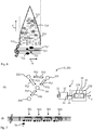
- FIGs. 3 to 6 A possible sonification of the ascertained functional information of the radar system 100 is shown purely by way of example.
- the upper part of the Figs. 3 to 6 is indicated symbolically in each case which functions F the radar system 100 carries out with respect to azimuth ⁇ and elevation ⁇ .
- a line of notes is shown in each case, in which the acoustic signal generated by the processing unit 23 of the sonification module 20 is shown in the form of notes.
- Fig. 3 it is shown by way of example that the radar system 100 carries out a basic search F11 over the entire azimuth range of 360 degrees, with the exception of a short section BS in the range of 180 degrees. This section BS is referred to as the blanking sector.
- the radar system also carries out a fine search F13 and a target tracking F14.
- a sonification of the execution status of the respective functions F11, F13 and F14 is shown.
- the execution status "function is being executed” is coded for each function F11, F13, F14 by a tone of a certain pitch.
- the tone representing the execution status is only generated when the respective function F11, F13, F14 is executed.
- the basic search F11 is in the example of Fig.
- the tone T11 is assigned and, according to the execution status of the basic search F11, is generated permanently and only interrupted by a pause during the blanking sector BS.
- the fine search F13 is in the example of Fig. 3 the tone T13 is assigned and is only generated briefly in accordance with the execution status of the fine search F13.
- the target tracking F14 is in the example of Fig. 3 the tone T14 is assigned and is only generated briefly in accordance with the execution status of the target tracking F14.
- the sonification of the system resource index of the radar system 100 is shown by way of example.
- the number of circles shown in each case in the upper part of the figures symbolically symbolizes the number of rays RB that are used for the respective function basic search F11, coarse search F12, fine search F13 and target tracking F14. Since the number of beams RB that can be generated within the time window and thus used for the various functions F11, F12, F13, F14 is limited, the time components of the respective function F11, F12, F13, F14 represent a system resource index. In Fig. 4 it is shown that only a basic search F11 and a coarse search F12 are carried out.
- a tone T11 assigned to the basic search F11 and a tone T12 assigned to the coarse search F12 are generated one after the other. These can also be generated as a two-tone sound at the same time.
- the mere generation of these tones T11, T12 represents the execution status of the functions.
- the functions basic search F11 and coarse search F12 are carried out at approximately the same time proportions. The tones T11, T12 are therefore generated with approximately the same volume.
- a fine search F13 is also carried out.
- the number of beams RB that are used for the coarse search F12 was compared to Fig. 4 decreased.
- a tone T13 is generated for the fine search, which sonifies the execution status of the fine search function F13. Since the time portion of the fine search F13 is small, which is represented by the system resource index of this function, the volume of the tone T13 is relatively low, which is shown in FIG Fig. 5 is symbolically represented by the size of the note representing the tone T13.
- the volume of the tone T12 belonging to the coarse search F12 is compared to Fig. 4 also decreased according to the decrease in the system resource metric.
- Fig. 6 is shown by way of example that in addition to the basic search F11, coarse search F12, fine search F13, target tracking F14 is also carried out.
- the number of rays RB used for the basic search F11 was reduced.
- the number of beams RB for the coarse search F12 has been reduced.
- the execution status of the target tracking F14 is sonicated by an additional tone T11.
- the volume of the tones T11 and T12 was corresponding to the reduced number of for the Functions basic search F11 and coarse search F12 reduced beams RB used.
- the assignment of the acoustic parameter volume to the system resource index and the acoustic parameter pitch to a respective function is purely exemplary and can be selected in any way.
- a user of the monitoring system 1 can configure the assignment via a corresponding input on the operating device 30.
- Fig. 7 shows in view (A) purely schematically and merely by way of example a communication system 200 which has a first communication node 201, e.g. B. a central control device (z. B. in the form of a command post), a second communication hub 202, z. B. in the form of a sensor, a third communication node 203, z. In the form of an effector, and a fourth communication hub 204, e.g. B. in the form of another sensor.
- a first communication node 201 e.g. B. a central control device (z. B. in the form of a command post)
- a second communication hub 202 e.g. B. in the form of a sensor
- a third communication node 203 e.g. B. in the form of another sensor.
- a fourth communication hub 204 e.g. B. in the form of another sensor.
- the first communication node 201 is connected to each of the further communication nodes 202, 203, 204 and can send data to or receive data from them. Furthermore, the first communication node 201 can forward or route the data received from in each case one of the further communication nodes 202, 203, 204 to a respective other communication node 202, 203, 204.
- the second communication node 202 is connected to the first and the third communication node 201, 203 and can accordingly Send data to and receive data from them and route data between the first and third communication nodes 201, 203.
- the third communication node 203 is connected to the first and second communication nodes 201, 202 and can accordingly send and receive data to and from them and route data between the first and second communication nodes 201, 202.
- the fourth communication node 204 is only connected to the first communication node 201 and can accordingly receive data from it and send it to it.
- the monitoring system 1 can be connected to the communication system 200 by means of the system interface 11 of the monitoring device 10, e.g. B. via a wireless connection or in that the monitoring system 1 is an integral part of one of the communication nodes 201-204 and is connected to this accordingly.
- the first communication node 201 is, for example, a central control device, the first communication node 201 enables the optionally integrated or connected monitoring system 1 that the monitoring device 10 receives functional information from all communication nodes 201-204, from which the monitoring device 10 generates a system status data set x for each time step.
- the sonification module 20 generates an associated audio signal y based on this system status data set x in accordance with the functional information contained therein as data content.
- the monitoring system 1 can also be used in communication systems that different from view (A) of Fig. 7 are constructed.
- the communication system 200 comprises at least two communication nodes 201, 202, 203, 204, the communication nodes performing at least the following functions: sending and receiving communication data to a further communication node 201, 202, 203, 204 and routing of received communication data to another Communication hub.
- Sending data from one communication hub to another is shown in view (A) of Fig. 7 symbolically represented by the arrows P12, P13, P14, P21, P23, P31, P32, P41.
- the monitoring module 10 determines, as function information, the function resource code for each of the functions, optionally for each communication node 201-204.
- the functional resource index for sending and receiving communication data can be defined, for example, by one or more of the following indexes: a data transmission rate, a data transmission time, a transmission waiting time, a signal-to-noise ratio (SNR, Signal to Noise Ratio), an MCS index ( Modulation and Coding Scheme), a UDP (User Datagram Protocol) data throughput or the like.
- the number of functional resources for routing can be defined, for example, by a number of data packets per time unit that are routed through the respective communication node.
- a line of notes is also shown in view (B), in which, purely by way of example and symbolically, the acoustic signal generated by the processing unit 23 of the sonification module 20 is shown in the form of notes.
- a functional resource code for the routing function and a functional resource code for sending to the further nodes connected to the respective node are determined for each communication node 201-204 and converted accordingly into an audio signal.
- the staves shown in each case show that one tone sequence SE1-SE4 is encoded in the audio signal one after the other for each node 201-204.
- a sequence of tone sequences SE1-SE4 is thus generated in accordance with a predetermined order of the nodes 201-204.
- the first tone of the respective sequence SE1-SE4 represents the functional resource code for the routing function of the respective node 201-204
- the further tones of the respective sequence SE1-SE4 represent the functional resource code for sending data from the respective node to a further node.
- a signal tone T0 can also be generated, which represents the start of a sequence.
- the tone sequence SE1 belonging to the first node 201 contains a tone of a predetermined length and pitch as the first note, which represents the function resource code for routing, and as the second note a tone of a predetermined length and pitch which is the function resource code for sending data from the first node 201 to the second node 202 represents, as the third note, a tone of a predetermined length and pitch, which represents the functional resource index for sending data from the first node 201 to the third node 203, and as the fourth note, a tone of a predetermined length and pitch which represents the functional resource index for sending data from the first node 201 to the fourth node 204.
- the tone sequence SE2 belonging to the second node 202 contains as the first note a tone of a predetermined length and pitch, which represents the functional resource index for the routing, as the second note a tone of a predetermined length and pitch, which the functional resource index for sending data from the second node 202 to the first node 201, and, as the third note, a tone of a predetermined length and pitch representing the functional resource index for sending data from the second node 202 to the third node 203. Since the second node 202 is not connected to the fourth node 204, the fourth note of the tone sequence SE2 is replaced by a rest.
- the tone sequence SE3 belonging to the third node 203 contains a tone of a predetermined length and pitch as the first note, which represents the functional resource index for routing, and as the second note a tone of a predetermined length and pitch, which represents the functional resource index for sending data from the third node 203 to the first node 201, and as the third note a tone of a predetermined length and pitch which is the functional resource index for sending data from the third node 203 to the second node 202 represents. Since the third node 203 is not connected to the fourth node 204, the fourth note of the tone sequence SE3 is replaced by a rest.
- the tone sequence SE4 belonging to the fourth node 204 contains as the first note a tone of a predetermined length and pitch, which represents the functional resource index for routing, and as the second note a tone of a predetermined length and pitch, which represents the functional resource index for the transmission represented by data from the fourth node 204 to the first node 201. Since the fourth node 204 is connected neither to the second node 202 nor to the third node 203, the third and fourth notes of the tone sequence SE4 are replaced by a rest.
- the fourth node 204 and the arrow P41 symbolizing the sending of data from the fourth node 204 to the first node 201 are each shown as dashed lines. This is intended to symbolize that the function code for routing node 204 is in a second area and the function code for sending data is also in a second area.
- the number of data packets routed through the fourth node 204, 201 may have risen above a first limit value and the data transmission rate for sending data from the fourth to the first node 204, 201 can be below one first limit value fell.
- tone sequence SE4 belonging to the fourth node 204 this can be perceived by the fact that the first note of the sequence SE4, which by its pitch represents the functional resource code for routing, and the second note of the sequence SE4, which by its pitch represents the functional resource code for sending of data at the first node 201, in view (B) of FIG Fig. 8 are each notated with a higher note than in view (B) of Fig. 7 .
- This change can be clearly perceived by a user of the monitoring system 1 when the audio signal y is converted by the electroacoustic converter 40.
- the first node 201, the arrow P14 symbolizing the sending of data from the first node 201 to the fourth node 204 and the arrow P21 symbolizing the sending of data from the second node 202 to the first node 201 are each shown as dashed lines. This is intended to symbolize that the function code for routing the first node 201 is in a second range and the function code for sending data from the first to the fourth node 201, 204 and for sending from the second to the first node 202, 201 is likewise lie in a second area.
- the number of data packets routed through the first node 201 may have risen above a first limit value and the data transmission rate for sending data from the second to the first node 202, 201 and for sending data from the first to the fourth node 201, 204 can each have fallen below a first limit value.
- the fourth node 204 and the arrow P41 symbolizing the transmission of data from the fourth node 204 to the first node 201 are each shown as dash-dot lines. This is to symbolize that the function code for the routing of Node 204 is in a third area and the function code for sending data is also in a third area.
- the number of data packets routed through the fourth node 204 may have risen above a second limit value that is higher than the first limit value for this, and the data transmission rate for sending data from the fourth to the first node 204, 201 can be below a second limit value may have fallen, which is smaller than the first limit value for this.
- FIG. 10 In view (A) of Fig. 10 is compared to view (A) of Fig. 9 It can be seen that the arrows P23 and P32, which symbolize the transmission of data from the second to the third node 202, 203 and from the third to the second node 203, 202, and the arrows P13 and P31, which symbolize the transmission of data from the first symbolize the third node 201, 203 and from the third to the first node 203, 201, are replaced by lines L13, L23. This is intended to symbolize that no data exchange takes place between the first and the third node 201, 203 and between the second and the third node 202, 203.
- the third node 203 thus no longer routes any data, nor does it send data to or receives data from the first and second nodes 201, 202.
- this can be perceived by the fact that the first note of the sequence SE3, which represents the functional resource code for routing by its pitch, the second note of the sequence SE3, which by its pitch represents the functional resource code for sending data to the first node 201, and the third note of the sequence SE3, which by its pitch represents the functional resource code for sending data to the second node 202, in view (B) of FIG Fig. 10 are each notated with a higher note than in the views (B) of Figs.
- a pitch changes continuously with the functional resource index.
- other acoustic parameters can also change continuously depending on the functional resource index.
- a flow chart of a method for monitoring functions F of a system S is shown schematically. This method can be carried out, for example, with the aid of a monitoring system 1 as described above.
- a first step M1 function information for at least one function F of the monitored system S is determined M1 for a current time step.
- the function information can contain one or more of the following information: an execution status of the function F, a function resource index, which represents the utilization of a resource provided by the system by the respective function, a system resource index F, which shows a proportion of the function in the utilization of the system S represents.
- a system status data record x is generated for the respective time step.
- the system status data set x contains the functional information of the at least one function F as data content, as has already been done with reference to FIG Fig. 10 was explained.
- the steps M1 and M2 can be carried out with the aid of the monitoring module 10, for example.
- acoustic parameters are determined in accordance with a predetermined one Assignment of acoustic parameters to the data contents of the system status data set x, e.g. B. using the processing unit 23 of the sonification module 20, as with reference to FIG Fig. 10 described by way of example.
- an audio signal y representing the acoustic parameters is generated for the respective time step, e.g. B. also with the aid of the processing unit 23 of the sonification module 20.
- the audio signal y can be converted into an output that can be perceived by a human user with the aid of an electroacoustic converter 30. Since a system status data set x is generated continuously for each time step and, as described, sonicated, information about the functions F of the monitored system S is continuously supplied to the user in the form of sounds. This advantageously integrates the ability of human hearing into the monitoring of system functions.
- the continuous monitoring resolved according to time steps in which the functional information is also continuously set to music according to a predetermined, systematic-functional assignment, offers the advantage that a complex acoustic image of the functions of the monitored system is created. This enables the human user to monitor a complex system in a simple, intuitive way.
Landscapes
- Engineering & Computer Science (AREA)
- Physics & Mathematics (AREA)
- General Physics & Mathematics (AREA)
- Radar, Positioning & Navigation (AREA)
- Remote Sensing (AREA)
- Electromagnetism (AREA)
- Theoretical Computer Science (AREA)
- Emergency Management (AREA)
- Business, Economics & Management (AREA)
- Multimedia (AREA)
- Health & Medical Sciences (AREA)
- Audiology, Speech & Language Pathology (AREA)
- General Health & Medical Sciences (AREA)
- Human Computer Interaction (AREA)
- General Engineering & Computer Science (AREA)
- Computer Networks & Wireless Communication (AREA)
- Selective Calling Equipment (AREA)
- Radar Systems Or Details Thereof (AREA)
Abstract
Ein Verfahren zur Überwachung von Funktionen eines Systems umfasst ein Ermitteln von Funktionsinformationen für zumindest eine Funktion des Systems für einen aktuellen Zeitschritt, wobei die Funktionsinformationen eine oder mehrere der folgenden Informationen beinhalten: einen Ausführungsstatus der Funktion, eine Funktionsressourcenkennzahl, welche eine Auslastung einer vom System bereitgestellten Ressource durch die jeweilige Funktion repräsentiert, eine Systemressourcenkennzahl, welche einen Anteil der Funktion an der Auslastung des Systems repräsentiert, ein Erzeugen eines Systemzustandsdatensatzes für den jeweiligen Zeitschritt, welcher die Funktionsinformationen der zumindest einen Funktion als Dateninhalte aufweist, ein Ermitteln akustischer Parameter gemäß einer vorbestimmten Zuordnung von akustischen Parametern zu den Dateninhalten des Systemzustandsdatensatzes und ein Erzeugen eines die akustischen Parameter repräsentierenden Audiosignals für den jeweiligen Zeitschritt.
Description
- Die vorliegende Erfindung betrifft ein Verfahren zur Überwachung von Funktionen eines Systems und ein Sonifikationsmodul.
- Zivile und militärische Systeme, wie z. B. Radarsysteme, Kommunikationssysteme, Waffensysteme, Fahrzeuge etc. werden zunehmend komplexer. Beispielsweise weist ein Fahrzeug, wie z. B. ein Luftfahrzeug oder ein militärisches Einsatzfahrzeug eine hohe Anzahl an Subsystemen auf, wie z. B. ein Antriebssystem zum Antrieb des Fahrzeugs, ein Kommunikationssystem zum Kommunizieren mit anderen Kommunikationsteilnehmern, ein Navigationssystem, gegebenenfalls ein Waffensystem und dergleichen. Ähnliche Situationen treten beispielsweise in Kraftwerken, bei der Luftraumüberwachung, in Kommunikations- oder Datennetzwerken und ähnlichen Systemen auf. Derartige Systeme sind in der Lage, eine Vielzahl verschiedener Funktionen gleichzeitig oder nacheinander auszuführen und weisen typischerweise einen hohen Vernetzungsgrad auf.
- Um einen effizienten und zuverlässigen Betrieb komplexer Systeme sicherzustellen, findet in der Regel eine Überwachung der Funktionen des Systems statt. Beispielsweise kann überwacht werden, ob bestimmte Systemfunktionen überhaupt ausgeführt werden und wie bestimmte Ressourcen des Systems durch die jeweilige Funktion ausgelastet werden. Um dem Bedienpersonal bzw. dem Überwachungspersonal die Überwachung der Systemfunktionen zu vereinfachen, werden Funktionsinformationen des Systems in Datensätze umgewandelt, welche typischerweise an graphischen Benutzerschnittstellen wie Bildschirmen als visuelle Darstellung ausgegeben werden. Gelegentlich werden solche visuellen Darstellungen durch akustische Signale in Form von Alarmen ergänzt, wobei ein Warnsignal erzeugt wird, wenn ein Ausfall einer Funktion oder eine Überlastung einer Systemressource durch eine Funktion festgestellt wird.
- Die Überwachung der Funktionen eines Systems stellt für das Bedienpersonal eine herausfordernde Aufgabe dar. Insbesondere die gleichzeitige Erfassung verschiedener Informationen aus einer visuellen Darstellung erfordert eine hohe Konzentrationsleistung.
- Vor diesem Hintergrund beschreibt die
US 2017/0330427 A1 ein Verfahren zur akustischen Darstellung eines Systemstatus, wobei verschiedene Systemzustände eines Systems ermittelt und daraus ein repräsentativer Systemstatus erzeugt wird, welcher mittels eines Wandlermoduls in eine musikalische Wiedergabe umgewandelt wird. Hierbei wird binär zwischen einem "akzeptablen" und einem "inakzeptablen" Systemzustand unterschieden, indem diese Zustände als konsonanter oder dissonanter Klang akustisch ausgegeben werden. - Es ist Aufgabe der vorliegenden Erfindung, verbesserte Lösungen zur Überwachung von Funktionen eines Systems zu finden.
- Diese Aufgabe wird jeweils durch die Gegenstände der unabhängigen Ansprüche gelöst.
- Gemäß einem ersten Aspekt der Erfindung umfasst ein Verfahren zur Überwachung von Funktionen eines Systems ein Ermitteln von Funktionsinformationen für zumindest eine Funktion des Systems für einen aktuellen Zeitschritt, wobei die Funktionsinformationen eine oder mehrere der folgenden Informationen beinhalten: einen Ausführungsstatus der Funktion, eine Funktionsressourcenkennzahl, welche eine Auslastung einer vom System bereitgestellten Ressource durch die jeweilige Funktion repräsentiert, eine Systemressourcenkennzahl, welche einen Anteil der Funktion an der Auslastung des Systems repräsentiert. In diesem Schritt werden somit Daten des Systems erfasst, welche einen Zustand einer jeweiligen Funktion des Systems beschreiben. Die Funktion kann hierbei durch eine physische Komponente des Systems ausgeführt werden. Insbesondere kann diese Komponente eine oder mehrere Funktionen ausführen und hierfür entsprechende Ressourcen, z. B. in Form elektrischer Leistung, Rechenleistung, etc. bereitstellen. Die Funktionsinformationen repräsentieren, wie beschrieben, ob eine Funktion überhaupt ausgeführt wird und/oder welche Ressourcen die Funktion bei der Ausführung aktuell benötigt. In Bezug auf die Ressourcen, welche die Funktion bei der Ausführung aktuell benötigt, kann beispielsweise erfasst werden, zu welchem Prozentsatz die Funktion die ihr von der ausführenden Komponente zur Verfügung gestellten Ressourcen ausnutzt, was einer Funktionsressourcenkennzahl entspricht. Alternativ oder zusätzlich kann erfasst werden, welchen Anteil die Ausführung der jeweiligen Funktion an durch die ausführende Komponente oder das System insgesamt bereitgestellten Ressourcen im Vergleich zu anderen Funktionen beansprucht. Dieser Anteil entspricht einer Systemressourcenkennzahl.
- In einem weiteren Schritt des Verfahrens erfolgt ein Erzeugen eines Systemzustandsdatensatzes für den jeweiligen Zeitschritt, welcher die Funktionsinformationen der zumindest einen Funktion als Dateninhalte aufweist. Weiterhin erfolgen ein Ermitteln akustischer Parameter gemäß einer vorbestimmten Zuordnung von akustischen Parametern zu den Dateninhalten des Systemzustandsdatensatzes und ein Erzeugen eines die akustischen Parameter repräsentierenden Audiosignals für jeden Zeitschritt.
- Gemäß einem zweiten Aspekt der Erfindung ist ein Überwachungssystem zur Überwachung von Funktionen eines Systems vorgesehen. Das erfindungsgemäße Überwachungssystem weist ein Überwachungsmodul mit einer Systemschnittstelle zum Anschluss an das zu überwachende System auf, wobei das Überwachungsmodul dazu eingerichtet ist, für einen aktuellen Zeitschritt Funktionsinformationen für zumindest eine Funktion des Systems zu ermitteln und einen Systemzustandsdatensatz zu erzeugen, welcher die Funktionsinformationen für zumindest eine Funktion des Systems zu einem jeweiligen Zeitschritt enthält, wobei die Funktionsinformationen eine oder mehrere der folgenden Informationen beinhalten: einen Ausführungsstatus der Funktion, eine Funktionsressourcenkennzahl, welche eine Auslastung einer vom System bereitgestellten Ressource durch die jeweilige Funktion repräsentiert, eine Systemressourcenkennzahl, welche einen Anteil der Funktion an der Auslastung des Systems repräsentiert.
- Das Überwachungssystem umfasst ferner ein Sonifikationsmodul mit einer mit dem Überwachungsmodul verbundenen Eingangsschnittstelle zum Empfang des Systemzustandsdatensatzes, mit einer Ausgangsschnittstelle und mit einer Verarbeitungseinheit, welche dazu eingerichtet ist, akustische Parameter gemäß einer vorbestimmten Zuordnung von akustischen Parametern zu den Dateninhalten des Systemzustandsdatensatzes zu ermitteln, ein die akustischen Parameter repräsentierendes Audiosignal zu erzeugen und an der Ausgangsschnittstelle auszugeben.
- Das Überwachungssystem ist somit insbesondere zur Ausführung des Verfahrens gemäß dem ersten Aspekt der Erfindung eingerichtet. Die für das Verfahren offenbarten Merkmale und Vorteile gelten somit auch für das Überwachungssystem als offenbart und umgekehrt.
- Eine der Erfindung zugrundeliegende Idee ist es, die Funktionen eines Systems kontinuierlich zu überwachen und die Kennzahlen, die einen Status der Funktion beschreiben, in ein Audiosignal umzuwandeln und somit zu sonifizieren. Dadurch können die Informationen bzw. Datenbeziehungen des Systemzustandsdatensatzes in wahrnehmbare Beziehungen in einem akustischen Signal umgewandelt werden. Insbesondere wird für jeden Zeitschritt ein Systemzustandsdatensatz erzeugt, in welchem für die überwachten Funktionen jeweils die Funktionsressourcenkennzahl und/oder die Systemressourcenkennzahl und/oder der Ausführungsstatus der Funktion enthalten ist. Diese als Inhalt in dem Datensatz enthaltenen Informationen werden gemäß einer vorbestimmten Zuordnung akustischen Parametern zugeordnet. Anhand des Inhalts des Systemzustandsdatensatzes, also z. B. anhand einer darin enthaltenen Funktionsressourcenkennzahl, wird gemäß einem vorbestimmten Algorithmus bzw. einer vorbestimmten Zuordnung ein Satz akustischer Parameter, wie z. B. Tonhöhe, Klangfarbe, Rhythmus, Lautstärke, Akkord, Modulation, Staccato u. ä. ermittelt und ein diese ermittelten Parameter repräsentierendes elektrisches oder elektromagnetisches Signal erzeugt, welches mittels eines elektroakustischen Wandlers in ein durch einen menschlichen Benutzer wahrnehmbares Signal umwandelbar ist. Insbesondere erfolgt durch die Sonifikation der im Systemzustandsdatensatz enthaltenen Kennzahlen für jeweils einen aktuellen Zeitschritt bei einer kontinuierlichen bzw. iterativen Ausführung des Verfahrens eine kontinuierliche klangliche Darstellung der Entwicklung der Kennzahlen.
- Einer der Vorteile der Erfindung ist es, dass die Fähigkeiten des menschlichen Gehörs in die Systemüberwachung eingebunden werden. Durch die Sonifikation der im Systemzustandsdatensatz enthaltenen Kennzahlen wird das Überwachungspersonal in die Lage versetzt, Änderungen, z. B. eine Änderung eines Ausführungsstatus einer Funktion, wahrzunehmen, ohne hierfür ausschließlich auf eine visuelle Darstellung angewiesen zu sein. Ferner wird die Fähigkeit des menschlichen Gehörs vorteilhaft ausgenutzt, bereits minimale Änderungen bzw. Unterschiede in Klängen wahrzunehmen. Damit wird es dem Bediener oder Benutzer erleichtert, auch bei einer sehr großen Anzahl an überwachten Funktionen auf einfache Weise den Überblick zu behalten. Eine Parallelisierung der Überwachung mit anderen Aufgaben wird damit ebenfalls erleichtert. Da bei menschlichen Benutzern Hören praktisch "nebenbei" erfolgt, wird es dem Benutzer erheblich erleichtert, eine Situation zu erfassen.
- Vorteilhafte Ausgestaltungen und Weiterbildungen ergeben sich aus den auf die unabhängigen Ansprüche rückbezogenen Unteransprüchen in Verbindung mit der Beschreibung.
- Gemäß einer Ausführungsform des Verfahrens kann das System eine oder mehrere der folgenden Systemkomponenten aufweisen, welche jeweils eine oder mehrere Funktionen ausführen: ein Sensor, welcher eine physikalische Größe misst, ein Transceiver, welcher elektrische, optische oder elektromagnetische Signale sendet und empfängt, ein Aktuator, welcher eine weitere Komponente des Systems oder ein Arbeitsmedium, z. B. ein Fluid oder Schüttgut, mechanisch mit einer Kraft beaufschlagt, z. B. ein Ventil oder eine Pumpe, ein Datennetzwerk, welches Daten zwischen verschiedenen Komponenten des Systems überträgt, ein Prozessor, welcher eingehende elektrische Signale verarbeitet und verarbeitete Signale als Ausgabewerte ausgibt.
- Gemäß einer weiteren Ausführungsform des Verfahrens kann das System ein Radarsystem aufweisen, welches innerhalb eines vorbestimmten Zeitfensters, beispielsweise nacheinander, eine oder mehrere der folgenden Funktionen ausführt: eine Basissuche zur Detektion neuer Objekte, Grobsuche zur Klassifizierung von Objekten, eine Feinsuche zur Erkennung von Objekten in einem vorbestimmten räumlichen Bereich, eine Zielverfolgung eines erkannten Objekts, wobei als Funktionsinformationen für jede der Funktionen der Ausführungsstatus und/oder die Systemressourcenkennzahl ermittelt werden, und wobei die Systemressourcenkennzahl durch einen Zeitanteil an dem Zeitfenster definiert ist, für welchen die jeweilige Funktion während des Zeitfensters ausgeführt wird. Das Radarsystem erzeugt innerhalb eines Zeitfensters eine bestimmte Anzahl an gerichteten, elektromagnetischen Radarstrahlen, wobei mit dieser Anzahl an Strahlen ein bestimmter Winkelbereich in Elevation und Azimut abgedeckt wird. Das Radarsystem kann verschiedene Funktionen ausführen, in welchen die Strahlen jeweils verschiedene Aufgaben erfüllen, nämlich die Aufgabe einer Basissuche, einer Grobsuche, einer Feinsuche oder einer Zielverfolgung. Die Systemressourcenkennzahl beinhaltet somit den Anteil an Zeit, den das Radarsystem darauf verwendet hat, die für die jeweilige Aufgabe erforderlichen Strahlen zu erzeugen. Durch die Sonifikation dieser im Systemdatensatz enthaltenen Kennzahl wird es einem Benutzer, der das Radarsystem überwacht, erleichtert, wahrzunehmen, wenn eine der Funktionen nicht mehr mit dem erforderlichen Zeitanteil ausgeführt wird. Beispielsweise kann jeder Funktion des Radarsystems ein Ton in einer bestimmten Tonhöhe als akustischer Parameter zugeordnet sein, welcher abhängig vom Ausführungsstatus der Funktion im Audiosignal enthalten ist oder nicht. Ferner kann z. B. die Lautstärke dieses Tons abhängig vom Zeitanteil, den diese Funktion innerhalb des Zeitfensters benötigt, variieren.
- Gemäß einer weiteren Ausführungsform des Verfahrens kann das System ein Kommunikationssystem mit zumindest zwei Kommunikationsknotenpunkten aufweisen, wobei die Kommunikationsknotenpunkte zumindest folgende Funktionen ausführen: ein Senden und Empfangen von Kommunikationsdaten an einen weiteren Kommunikationsknotenpunkt, ein Routing von empfangenen Kommunikationsdaten an einen weiteren Kommunikationsknotenpunkt, wobei als Funktionsinformationen die Funktionsressourcenkennzahl für jede der Funktionen ermittelt wird. Optional kann die Funktionsressourcenkennzahl für das Senden und Empfangen von Kommunikationsdaten durch eine oder mehrere der folgenden Kennzahlen definiert sein: eine Datenübertragungsrate, eine Datensendezeit, eine Sendewartezeit, ein Signal-Rausch-Verhältnis (SNR, Signal to Noise Ratio), ein MCS-Index (Modulation and Coding Scheme), ein UDP (User Datagram Protocol) Datendurchsatz oder dergleichen. Die Funktionsressourcenzahl für das Routing kann optional durch eine Anzahl an Datenpaketen pro Zeiteinheit definiert sein, die durch den jeweiligen Kommunikationsknotenpunkt geleitet werden. Auf diese Weise wird jeweils eine absolute oder relative Kennzahl angegeben, die beschreibt, zu welchem Anteil die Funktion die ihr von dem Knoten zur Verfügung gestellten Ressourcen ausnutzt. Die Sonifikation dieser Kennzahlen erleichtert erheblich die Überwachung der Funktionsfähigkeit eines Kommunikationssystems. Die Kommunikationsknotenpunkte können hierbei durch verschiedene Subsysteme gebildet sein. Beispielsweise könnten einer oder mehrere Knotenpunkte durch ein Sensorsystem, z. B. durch Radarsysteme wie oben beschrieben, durch ein Waffensystem (Effektor) und/oder durch einen Gefechtsstand gebildet sein.
- Gemäß einer weiteren Ausführungsform des Verfahrens können die akustischen Parameter einen oder mehrere der folgenden Parameter umfassen:
Tonhöhe, Klangfarbe, Rhythmus, Lautstärke, Akkord, Modulation, Staccato oder dergleichen. - Gemäß einer Ausführungsform des Überwachungssystem kann das Sonifikationsmodul eine Steuerschnittstelle aufweisen und zusätzlich kann eine mit der Steuerschnittstelle des Sonifikationsmoduls verbundene Bedieneinrichtung vorgesehen sein, welche dazu eingerichtet ist, basierend auf einer Benutzereingabe einen Steuerbefehl zu erzeugen, wobei das Sonifikationsmodul dazu eingerichtet ist, die Erzeugung des Audiosignals gemäß dem Steuerbefehl anzupassen. Die Bedieneinrichtung des Überwachungssystems kann allgemein eine Eingabeeinrichtung zur Eingabe von Steuerbefehlen durch den Benutzer aufweisen, z. B. in Form einer Tastatur oder entsprechender Schaltflächen auf einem berührungssensitiven Display, wobei das Sonifikationsmodul dazu eingerichtet ist, die Erzeugung des Audiosignals gemäß den eingegebenen Steuerbefehlen anzupassen. Die Bedieneinrichtung kann damit zum Modifizieren von Einstellungen des Sonifikationsmoduls genutzt werden. Allgemein enthält ein Steuerbefehl Steuerdaten, auf denen basierend das Sonifikationsmodul die Erzeugung des Audiosignals anpasst. Insbesondere ist denkbar, dass die vorbestimmte Zuordnung von akustischen Parametern zu den Funktionsinformationen basierend auf den Steuerbefehlen vorgebbar ist. Beispielsweise kann vorgesehen sein, dass der Benutzer die Zuordnung eines bestimmten Tons zu einer bestimmten Funktionsressourcenkennzahl oder eine bestimmten Systemressourcenkennzahl oder einem Ausführungsstatus einer jeweiligen Funktion ändern kann. Somit kann die Sonifikation individuell an die Wünsche des Benutzers angepasst werden.
- Gemäß einer weiteren Ausführungsform des Überwachungssystem kann die Bedieneinrichtung eine Sensoreinrichtung zum Erfassen von Bewegungen des Benutzers und/oder sprachlichen Äußerungen eines Benutzers als Benutzereingabe aufweisen und dazu eingerichtet sein, den Steuerbefehl basierend auf der erfassten Bewegung und/oder auf der erfassten Äußerung zu erzeugen. Die Eingabeeinrichtung kann somit auch als interaktive Eingabeeinrichtung gestaltet sein, welche einen Sensor aufweist, mit dem Gesten, Bewegungen, sprachliche Äußerungen oder dergleichen erfassbar sind, welchen ein Steuerbefehl zugeordnet ist. Der Sensor kann beispielsweise als optischer Sensor wie z. B. eine Kamera, als Eyetracker, als Datenhandschuh, als Mikrophon zur Spracherkennung oder dergleichen realisiert sein. Die zweite Bedieneinrichtung erleichtert dem Benutzer die intuitive Bedienung des Überwachungssystems.
- Gemäß einer Ausführungsform des Überwachungssystems kann das Sonifikationsmodul dazu eingerichtet sein, basierend auf dem Steuerbefehl, die Zuordnung von akustischen Parametern zu den Dateninhalten des Systemzustandsdatensatzes zu ändern.
- Gemäß einer weiteren Ausführungsform ist das Überwachungsmodul dazu eingerichtet, für einen aktuellen Zeitschritt Funktionsinformationen für eine Vielzahl von Funktionen des Systems zu ermitteln und einen Systemzustandsdatensatz zu erzeugen, welcher die Funktionsinformationen für die Vielzahl von Funktion des Systems zu einem jeweiligen Zeitschritt enthält, wobei der Steuerbefehl Steuerdaten enthält, welche eine Funktionsauswahl bestehend aus zumindest einer Funktion aus der Vielzahl von Funktion enthalten, und wobei das Sonifikationsmodul dazu eingerichtet ist, basierend auf den Steuerdaten aus dem Systemzustandsdatensatz Funktionsinformationen für die Funktionsauswahl auszuwählen und das Audiosignal nur für die Funktionsinformationen der ausgewählten Funktionsinformationen zu erzeugen. Demnach kann Funktionsüberwachung eines Systems, welches eine Vielzahl von Teilsystemen mit verschiedenen Funktionen aufweist, welche optional ihrerseits weitere Teilsysteme mit Funktionen aufweisen können, flexibel angepasst werden. Durch einen Steuerbefehl kann ein Benutzer diejenigen Funktionen, deren Funktionskennzahlen sonifiziert werden sollen, gezielt auswählen. Somit kann eine Detailtiefe der Funktionsüberwachung auf einfache und effiziente Weise angepasst werden.
- Im Folgenden wird die Erfindung unter Bezugnahme auf die Figuren der Zeichnungen erläutert. Von den Figuren zeigen:
- Fig. 1
- eine schematische Darstellung eines Überwachungssystems gemäß einem Ausführungsbeispiel der Erfindung als Blockschaltbild;
- Fig. 2
- eine schematische Darstellung eines Überwachungssystems gemäß einem Ausführungsbeispiel der Erfindung, welches zur Überwachung eines Radarsystems verwendet wird;
- Fig. 3
- eine symbolisch-funktionale Darstellung einer Sonifikation von Funktionsinformationen eines Radarsystems in einem Verfahren gemäß einem Ausführungsbeispiel der Erfindung mittels des Überwachungssystems gemäß
Fig. 2 ; - Fig. 4
- eine symbolisch-funktionale Darstellung einer Sonifikation von Funktionsinformationen eines Radarsystems in einem Verfahren gemäß einem Ausführungsbeispiel der Erfindung mittels des Überwachungssystems gemäß
Fig. 2 ; - Fig. 5
- eine symbolisch-funktionale Darstellung einer Sonifikation von Funktionsinformationen eines Radarsystems in einem Verfahren gemäß einem Ausführungsbeispiel der Erfindung mittels des Überwachungssystems gemäß
Fig. 2 ; - Fig. 6
- eine symbolisch-funktionale Darstellung einer Sonifikation von Funktionsinformationen eines Radarsystems in einem Verfahren gemäß einem Ausführungsbeispiel der Erfindung mittels des Überwachungssystems gemäß
Fig. 2 ; - Fig. 7
- eine schematische Darstellung eines Überwachungssystems gemäß einem Ausführungsbeispiel der Erfindung, welches zur Überwachung eines Kommunikationssystems verwendet wird;
- Fig. 8
- eine symbolisch-funktionale Darstellung einer Sonifikation von Funktionsinformationen eines Kommunikationssystems in einem Verfahren gemäß einem Ausführungsbeispiel der Erfindung mittels des Überwachungssystems gemäß
Fig. 7 ; - Fig. 9
- eine symbolisch-funktionale Darstellung einer Sonifikation von Funktionsinformationen eines Kommunikationssystems in einem Verfahren gemäß einem Ausführungsbeispiel der Erfindung mittels des Überwachungssystems gemäß
Fig. 7 ; - Fig. 10
- eine symbolisch-funktionale Darstellung einer Sonifikation von Funktionsinformationen eines Kommunikationssystems in einem Verfahren gemäß einem Ausführungsbeispiel der Erfindung mittels des Überwachungssystems gemäß
Fig. 7 ; - Fig. 11
- eine schematische Darstellung der Funktionsweise eines Sonifikationsmoduls eines Überwachungssystems gemäß einem Ausführungsbeispiel der Erfindung; und
- Fig. 12
- ein Ablaufdiagramm eines Verfahrens gemäß einem Ausführungsbeispiel der Erfindung.
- In den Figuren bezeichnen dieselben Bezugszeichen gleiche oder funktionsgleiche Komponenten, soweit nichts Gegenteiliges angegeben ist.
-
Fig. 1 zeigt beispielhaft ein Überwachungssystem 1 zur Überwachung von Funktionen F eines Systems S. Das zu überwachende System S kann verschiedene Systemkomponenten K aufweisen, welche jeweils eine oder mehrere Funktionen F ausführen. Beispielsweise kann das System S ein Radarsystem 100 sein oder aufweisen, welches als Systemkomponenten K einen Radartransceiver 101 zum Erzeugen eines elektromagnetischen Signals und eine Antenne 102 zum gerichteten Abstrahlen des Signals aufweist, wie dies beispielhaft inFig. 2 dargestellt ist. Weiterhin beispielhaft kann das System S ein Kommunikationssystem 200 mit mehreren Kommunikationsknotenpunkten 201, 202, 203, 204 als Systemkomponenten sein oder ein solches Kommunikationssystem 200 aufweisen. Weiterhin kommen als System S beispielsweise Fahrzeuge, insbesondere Luftfahrzeuge, Kraftwerke, Materialfördersysteme oder dergleichen in Frage. Allgemein kann das System S als Systemkomponenten K beispielsweise aufweisen einen Sensor, welcher eine physikalischen Größe misst, einen Transceiver, welcher elektrische, optische oder elektromagnetische Signale sendet und empfängt, einen Aktuator, welcher eine weitere Komponente des Systems oder ein Arbeitsmedium mechanisch mit einer Kraft beaufschlagt, ein Datennetzwerk, welches Daten zwischen verschiedenen Komponenten des Systems überträgt, einen Prozessor, welcher eingehende elektrische Signale verarbeitet und verarbeitetet Signale als Ausgabewerte ausgibt. - Innerhalb des überwachten Systems S wird der Zustand einer jeweiligen Funktion F zu jedem Zeitpunkt oder aktuellen Zeitschritt durch Funktionsinformationen beschrieben. Diese Funktionsinformationen können insbesondere einen Ausführungsstatus der Funktion F, also die Information, ob die jeweilige Funktion zu dem aktuellen Zeitpunkt ausgeführt wird, beinhalten. Eine Funktionsinformation kann alternativ oder zusätzlich in einer Funktionsressourcenkennzahl beinhaltet sein, welche eine Auslastung einer vom System bereitgestellten Ressource durch die jeweilige Funktion repräsentiert, oder in einer Systemressourcenkennzahl, welche einen Anteil der Funktion an der Auslastung des Systems repräsentiert.
- Wie in
Fig. 1 rein beispielhaft dargestellt ist, weist das Überwachungssystem 1 ein Überwachungsmodul 10, ein Sonifikationsmodul 20 und eine Bedieneinrichtung 30 auf. Das Überwachungsmodul 10 weist eine Systemschnittstelle 11 und eine Übergabeschnittstelle 12 auf. Das Überwachungsmodul 10 kann zumindest einen Prozessor (nicht dargestellt) aufweisen, welcher beispielsweise durch ein ASIC, FPGA, PLD, einen digitalen Signalprozessor, einen Mikrocontroller oder eine andere geeignete Recheneinrichtung realisiert sein kann, die in der Lage ist, an der Systemschnittstelle 11 eingehende Signale zu verarbeiten und verarbeitete Signale in Ausgabewerte zu verwandeln, die an der Übergabeschnittstelle 12 ausgegeben werden können. Der Prozessor des Überwachungsmoduls 10 kann überdies über einen internen Speicher verfügen. Es kann auch möglich sein, dass ein separater (inFig. 1 nicht explizit gezeigter) Speicherbaustein vorgesehen ist, der mit dem Prozessor gekoppelt ist, und von dem der Prozessor gespeicherte Daten zur Verarbeitung abrufen kann. Die Systemschnittstelle 11 und die - Übergabeschnittstelle 12 können jeweils zur kabelgebundenen oder kabellosen Daten- bzw. Signalübertragung eingerichtet sein. Beispielsweise können die Systemschnittstelle 11 und/oder die Übergabeschnittstelle 12 als Bus-Schnittstelle, z. B. als USB-Schnittstelle oder als CAN-Bus-Schnittstelle oder dergleichen realisiert sein. Auch ist denkbar, die Systemschnittstelle 11 und/oder die Übergabeschnittstelle 12 als WiFi-Schnittstelle, als Bluetooth® Schnittstelle, als optische Schnittstelle oder dergleichen zu realisieren.
- Wie in
Fig. 1 symbolisch dargestellt ist, ist die Systemschnittstelle 11 zur Verbindung mit dem zu überwachenden System S vorgesehen. Beispielsweise kann die Systemschnittstelle 11 mit Sensoren (nicht dargestellt) des Systems S verbunden sein, welche physikalische Größen erfassen und als Funktionsinformationen bereitstellen. Das Überwachungsmodul 10 ist dazu eingerichtet, für einen aktuellen Zeitschritt Funktionsinformationen für zumindest eine Funktion F des Systems S zu ermitteln und einen Systemzustandsdatensatz x zu erzeugen, welcher die Funktionsinformationen für zumindest eine Funktion F des Systems zu einem jeweiligen Zeitschritt enthält. Das Überwachungsmodul 10 erhält somit von dem überwachten System S erhaltenen Daten der verschiedenen Systemfunktionen F, z. B. in Form von Sensordaten oder in Form von vorverarbeiteten Daten, und ermittelt daraus die Funktionsinformationen, das heißt, den Ausführungsstatus der jeweiligen Funktion F, die Funktionsressourcenkennzahl und/oder die Systemressourcenkennzahl. Die ermittelten Funktionsinformationen werden dann in einem Systemzustandsdatensatz x zusammengefasst. Ein Systemzustandsdatensatz x ist symbolisch inFig. 11 dargestellt. Wie inFig. 11 symbolisch und rein beispielhaft dargestellt, enthält der Systemzustandsdatensatz x verschiedene Funktionsinformationen als Dateninhalte x1, x2...xN. Beispielsweise kann der Dateninhalt x1 als Wert v1 den Ausführungsstatus einer Funktion F in Form von "0" ("wird nicht ausgeführt") oder "1" ("wird ausgeführt") enthalten, der Dateninhalt x2 als Wert v2 eine Systemressourcenkennzahl oder eine Funktionsressourcenkennzahl enthalten usw. Allgemein weist jeder Dateninhalt xN einen Wert vN auf. Die Funktionsinformationen können für eine oder mehrere Funktionen F in dem Systemzustandsdatensatz x als Dateninhalte xN enthalten sein. Für einen aktuellen Zeitschritt wird je ein Systemdatensatz erzeugt. Optional kann eine Bedieneinrichtung 30, wie inFig. 1 dargestellt, an eine Steuerschnittstelle 24 des Sonifikationsmoduls 20 angeschlossen werden, um z. B. eine Konfiguration der Sonifikation zu veranlassen, wie dies nachfolgend noch im Detail erläutert wird. - Das Sonifikationsmodul 20 weist eine Eingangsschnittstelle 21, eine Ausgangsschnittstelle 22, eine Steuerschnittstelle 24 und eine Verarbeitungseinheit 23 auf. Die Eingangsschnittstelle 21 ist mit der Übergabeschnittstelle 12 des Überwachungsmoduls 10 verbunden und kann als Datenschnittstelle zur kabelgebundenen oder kabellosen Datenübertragung realisiert sein. Beispielsweise kann die Eingangsschnittstelle 21 als kabelgebundene Bus-Schnittstelle, z. B. als USB-Schnittstelle oder als CAN-Bus-Schnittstelle realisiert sein. Auch ist denkbar, die Eingangsschnittstelle 21 als WiFi-Schnittstelle, als Bluetooth® Schnittstelle, als optische Schnittstelle oder dergleichen zu realisieren. Die Ausgangsschnittstelle 22 und die Steuerschnittstelle 24 können ebenfalls als Datenschnittstelle zur kabelgebundenen oder kabellosen Datenübertragung realisiert sein.
- Die Verarbeitungseinheit 23 kann als ein Computer mit zumindest einem Prozessor 23A und zumindest einem Datenspeicher 23B realisiert sein. Der Prozessor 23A kann beispielsweise ein ASIC, FPGA, PLD, ein digitaler Signalprozessor, ein Mikrocontroller oder eine andere geeignete Recheneinrichtung sein, die in der Lage ist, eingehende, die Funktionsinformationen enthaltende Signale zu verarbeiten und verarbeitete Funktionsinformationen in Audiosignale zu verwandeln. Der Datenspeicher 23B kann insbesondere ein nicht-flüchtiger Datenspeicher, wie z. B. ein EEPROM oder eine Festplatte sein, welcher ein Softwareprogramm speichert, welches dazu ausgelegt ist, den Prozessor 23A zur Ausführung von Schritten zur Sonifikation der Funktionsinformationen zu veranlassen. Das Sonifikationsmodul 20 kann auch rein als Softwaremodul bzw. Softwareprogramm realisiert sein, welches dazu ausgelegt ist, einen Prozessor zur Ausführung von Schritten zur Sonifikation der Funktionsinformationen zu veranlassen. Beispielsweise ist denkbar, dass das Überwachungsmodul 10 und die Verarbeitungseinheit 23 des Sonifikationsmoduls 20 auf denselben Prozessor und/oder Datenspeicher zurückgreifen.
-
Fig. 11 zeigt schematisch die Funktionsweise der Verarbeitungseinheit 23 des Sonifikationsmoduls 20. Die Verarbeitungseinheit 23 ermittelt für jeden Dateninhalt xl...xN des an der Eingangsschnittstelle 21 von dem Überwachungsmodul 10 erhaltenen Systemzustandsdatensatz x akustische Parameter P1, P2...PN. Die akustischen Parameter P1, P2...PN können z. B. eine Tonhöhe, eine Klangfarbe, ein Rhythmus, eine Lautstärke, ein Akkord, eine Modulation, ein Staccato oder ähnliche Parameter sein. Für jeden Dateninhalt xl...xN kann z. B. eine Look-up-Tabelle vorliegen, in welchem für jeden Wert v1 bestimmte akustische Parameter P1, P2...PN hinterlegt sind. Z. B. können für den Dateninhalt x2, welcher beispielsweise die Systemressourcenkennzahl einer Funktion F enthalten kann, bei einem Wert v2, eine bestimmte Tonhöhe und eine bestimmte Klangfarbe als Parameter P1, P2 in der Look-up-Tabelle hinterlegt sein. Gemäß dieser jeweils vorbestimmten, systematischen Zuordnung von akustischen Parametern zu den Funktionsinformationen ermittelt die Verarbeitungseinheit 23 die akustischen Parameter. - Ferner erzeugt die Verarbeitungseinheit 23 ein die ermittelten akustischen Parameter repräsentierendes Audiosignal y und gibt das Audiosignal y an der Ausgangsschnittstelle 22 aus, wie dies in
Fig. 11 symbolisch dargestellt ist. Damit werden die Funktionsinformationen durch die Verarbeitungseinheit 23 gemäß einer vorbestimmten Regel abhängig von den die Funktionsinformationen enthaltenden Dateninhalten als Audiosignal codiert. Es kann hierbei beispielsweise vorgesehen sein, dass die Zuordnung der Parameter zu den Dateninhalten eine sequenzielle Abfolge vorsieht, wonach die den Dateninhalten x1-xN zugeordneten Parameter, also Töne, Lautstärke etc. aufeinander folgend in dem akustischen Signal codiert werden. Beispielsweise kann zuerst das akustische Parameterset P1,...,PN zu Dateninhalt x1, danach das akustische Parameterset P1,...,PN zu Dateninhalt x2, usw. in dem akustischen Signal ausgegeben werden. Alternativ oder zusätzlich ist auch denkbar, dass zwei oder mehr Dateninhalte x1, x2,...xN gleichzeitig, z. B. als Mehrklang in das akustische Signal codiert werden. - Das Audiosignal y wird an der Ausgangsschnittstelle 22 bereitgestellt und kann mittels eines optionalen elektroakustischen Wandlers 40, welcher z. B. wie in
Fig. 1 dargestellt als Kopfhörer realisiert sein kann, in ein durch einen menschlichen Benutzer wahrnehmbares akustisches Signal umgewandelt werden. Der optionale elektroakustische Wandler 40 weist allgemein zumindest eine Schallquelle, optional zumindest zwei oder mehr Schallquellen auf, welche dazu eingerichtet sind, Schall basierend auf dem Audiosignal y zu erzeugen. - Wie in
Fig. 1 weiterhin dargestellt ist, ist die Bedieneinrichtung 30 mit dem Sonifikationsmodul 20 verbunden. Insbesondere kann die Bedieneinrichtung 30 mit der Steuerschnittstelle 24 des Sonifikationsmoduls 20 verbunden sein. Die Bedieneinrichtung 30 kann insbesondere als ein Computer mit zumindest einem Prozessor (nicht dargestellt) und zumindest einem Datenspeicher (nicht dargestellt) realisiert sein. Der Prozessor kann beispielsweise ein ASIC, FPGA, PLD, digitaler Signalprozessor, ein Mikrocontroller oder eine andere geeignete Recheneinrichtung sein, die in der Lage ist, eingehende Signale zu verarbeiten und verarbeitete Signale in Ausgabewerte zu verwandeln. Die Bedieneinrichtung 30 kann insbesondere einen separaten Prozessor aufweisen oder mit dem Sonifikationsmodul 20 und/oder mit dem Überwachungsmodul 10 gemeinsam auf einen Prozessor und/oder Datenspeicher zurückgreifen.
Die Bedieneinrichtung 30 kann insbesondere eine Eingabeeinrichtung 31 aufweisen, welche z. B. als Tastatur oder allgemein als Eingabeschnittstelle realisiert ist, über welche ein Benutzer Benutzereingaben in Form von Steuerbefehlen eingeben kann. Die Bedieneinrichtung 30 kann basierend auf den Steuerbefehlen Steuerdaten bzw. Steuersignale erzeugen, auf Basis derer das Sonifikationsmodul 20 zur Ausführung vorbestimmter Schritte veranlasst wird. Dies wird nachfolgend noch im Detail erläutert. Die Bedieneinrichtung 30 kann alternativ oder zusätzlich zu der Eingabeeinrichtung 31 eine Sensoreinrichtung 32 zum Erfassen von Bewegungen des Benutzers und/oder sprachlichen Äußerungen eines Benutzers als Benutzereingabe aufweisen und dazu eingerichtet sein, den Steuerbefehl C basierend auf der erfassten Bewegung und/oder auf der erfassten Äußerung zu erzeugen. InFig. 1 ist symbolisch dargestellt, dass der optionale akustische Wandler 40 ein Mikrophon 41 aufweist, welcher eine Sensoreinrichtung 32 zum Erfassen sprachlicher Äußerungen bildet. Die Sensoreinrichtung 32 kann beispielsweise auch als optischer Sensor, durch in einen sogenannten Datenhandschuh integrierte kapazitive Sensoren oder in ähnlicher Weise realisiert sein. Optional kann die Bedieneinrichtung 30 einen Prozessor oder allgemein einen Signalwandler (nicht dargestellt) aufweisen, welcher zur Umwandlung der von der Sensoreinrichtung 32 erfassten Daten in Steuerbefehle eingerichtet ist. - Das Sonifikationsmodul 20 kann insbesondere dazu eingerichtet sein, basierend auf dem durch die Bedieneinrichtung 30 erzeugten Steuerbefehl C die Zuordnung von akustischen Parametern zu den Dateninhalten des Systemzustandsdatensatzes x zu ändern. Durch einen entsprechenden Steuerbefehl, den der Benutzer als Bedienereingabe an der Bedieneinrichtung 30 tätigt, kann der Benutzer somit eine Zuordnung der akustischen Parameter zu den Dateninhalten des Systemzustandsdatensatzes x konfigurieren. Beispielsweise kann der Benutzer für eine bestimmte Funktion eine Tonhöhe und/oder eine Klangfarbe, also z. B. den Klang einer Gitarrenseite, in einer Benutzereingabe auswählen. Die Bedieneinrichtung 30 erzeugt basierend auf der Eingabe einen entsprechenden Steuerbefehl C, welcher die Verarbeitungseinheit 23 des Sonifikationsmoduls 20 veranlasst, die z. B. in einer Look-up-Tabelle gespeicherte Zuordnung von Dateninhalt zu akustischem Parameter entsprechend dem Steuerbefehl C zu ändern. Das Audiosignal y wird dann dementsprechend erzeugt.
Wenn durch das Überwachungsmodul 10 Funktionsinformationen für eine Vielzahl von Funktionen F des Systems S ermittelt werden, wird vorzugsweise ein Systemzustandsdatensatz x erzeugt, welcher die Funktionsinformationen für die gesamte Vielzahl von Funktion F des Systems zu dem jeweiligen Zeitschritt enthält. Mittels der Bedieneinrichtung 30 kann optional ein Steuerbefehl C erzeugt werden, z. B. durch eine entsprechende Benutzereingabe, welcher Steuerdaten enthält, die eine Funktionsauswahl bestehend aus zumindest einer Funktion F aus der Vielzahl von Funktion F enthalten. Über die Bedieneinrichtung 30 kann der Benutzer somit eine oder mehrere überwachte Funktionen des Systems auswählen. Optional ist das Sonifikationsmodul 20 dazu eingerichtet, basierend auf den Steuerdaten aus dem Systemzustandsdatensatz x die Funktionsinformationen für die Funktionsauswahl auszuwählen und das Audiosignal nur für die Funktionsinformationen der ausgewählten Funktionsinformationen zu erzeugen. Somit kann über den Steuerbefehl eine Auswahl getroffen werden, die definiert, von welchen Funktionen F des Systems S die Funktionsinformationen durch das Sonifikationsmodul 20 sonifiziert werden sollen. Damit kann die Detailtiefe der Sonifikation variabel verändert werden. - In
Fig. 2 ist in Ansicht (A) rein schematisch und lediglich beispielhaft ein zu überwachendes System S gezeigt, welches ein Radarsystem 100 aufweist. Das Radarsystem 100 weist einen Radartransceiver 101 auf, der dazu eingerichtet ist, ein elektromagnetisches Signal mit einer vorbestimmten Frequenz zu erzeugen und ein von einem Objekt (nicht dargestellt) reflektiertes Antwortsignal zu ermitteln. Das Radarsystem 100 weist außerdem eine mit dem Radartransceiver 101 verbundene Radarantenne 102 auf, welche das vom Radartransceiver 101 erzeugte Signal als Radarstrahl RB in gerichteter Weise abstrahlt. Wie dies in Ansicht (B) vonFig. 2 in vereinfachter Weise dargestellt ist, werden zur Abdeckung eines hemisphärischen Raums um das Radarsystem 100 eine Vielzahl einzelner Strahlen RB in verschiedenen Richtungen, welche jeweils durch einen Azimutwinkel Ψ und einen Elevationswinkel α definiert sind, gleichzeitig oder nacheinander abgestrahlt. Die Einzelstrahlen RB können jeweils für verschiedene Aufgaben des Radarsystems 100 verwendet werden. Das Radarsystem 100 kann innerhalb des vorbestimmten Zeitfensters, das zur Abdeckung der Hemisphäre durch die einzelnen Strahlen RB und damit eine Basissuche zur Detektion neuer Objekte und/oder ein Grobsuche zur Klassifizierung von Objekten und/oder eine Feinsuche zur Erkennung von Objekten in einem vorbestimmten räumlichen Bereich und/oder eine Zielverfolgung eines erkannten Objekts als Funktionen F ausführen. - Zur Überwachung der Funktionen F des Radarsystems 100 kann das Überwachungsmodul 10 über dessen Systemschnittstelle 11 mit dem Radartransceiver 101 oder allgemein mit dem Radarsystem 100 verbunden sein, wie dies in Ansicht (A) von
Fig. 2 schematisch dargestellt ist. Das - Überwachungsmodul 10 greift am Radarsystem 100 Daten ab, z. B. in Form von Rohdaten und ermittelt für jede der Funktionen, die das Radarsystem 100 in Bezug auf die Einzelstrahlen RB ausführt, den Ausführungsstatus und/oder die Systemressourcenkennzahl als Funktionsinformation. Die Systemressourcenkennzahl ist hierbei durch einen Zeitanteil an dem Zeitfenster definiert, für welchen die jeweilige Funktion während des Zeitfensters ausgeführt wird. Für jeden Zeitschritt, wobei ein Zeitschritt hierbei insbesondere der Dauer des vorbestimmten Zeitfensters entsprechen kann, erzeugt das Überwachungsmodul 10 jeweils einen Systemzustandsdatensatz x, in dem die genannten Funktionsinformationen als Dateninhalte xN enthalten sind. Wie dies in Ansicht (A) von
Fig. 2 schematisch dargestellt ist, wird der Systemzustandsdatensatz x an das Sonifikationsmodul 20 weitergeleitet, welches darauf basierend ein Audiosignal y erzeugt, wie dies allgemein anhand derFign. 1 und11 erläutert wurde. Optional kann eine Bedieneinrichtung 30, wie inFig. 1 dargestellt und wie bereits erläutert, an das Sonifikationsmodul 20 angeschlossen werden, um z. B. eine Konfiguration der Sonifikation zu veranlassen, z.B. indem eine Funktionsauswahl getroffen, um nur bestimmte Funktionen des Radarsystems zu sonifizieren, oder indem die Zuordnung akustischer Parameter angepasst wird. - In den
Fign. 3 bis 6 ist rein beispielhaft eine mögliche Sonifikation der ermittelten Funktionsinformationen des Radarsystems 100 dargestellt. In dem oberen Teil derFign. 3 bis 6 ist jeweils symbolisch angedeutet, welche Funktionen F das Radarsystem 100 in Bezug auf Azimut Ψ und Elevation α ausführt. Im unteren Teil derFign. 3 bis 6 ist jeweils eine Notenzeile dargestellt, in welcher das durch die Verarbeitungseinheit 23 des Sonifikationsmoduls 20 erzeugte akustische Signal in Form von Noten dargestellt ist. - In
Fig. 3 ist beispielhaft dargestellt, dass das Radarsystem 100 eine Basissuche F11 über den gesamten Azimutbereich von 360 Grad ausführt, mit Ausnahme eines kurzen Abschnitts BS im Bereich von 180 Grad. Dieser Abschnitt BS wird als Blanking Sektor bezeichnet. Ferner führt das Radarsystem eine Feinsuche F13 und eine Zielverfolgung F14 durch. In der inFig. 3 gezeigten Notenzeile ist eine Sonifikation des Ausführungsstatus der jeweiligen Funktionen F11, F13 und F14 dargestellt. Der Ausführungsstatus "Funktion wird ausgeführt" wird für jede Funktion F11, F13, F14 durch einen Ton einer bestimmten Tonhöhe codiert. Der den Ausführungsstatus repräsentierende Ton wird nur erzeugt, wenn die jeweilige Funktion F11, F13, F14 ausgeführt wird. Der Basissuche F11 ist im Beispiel vonFig. 3 der Ton T11 zugeordnet und wird, entsprechend dem Ausführungsstatus der Basissuche F11, dauerhaft erzeugt und nur während des Blanking Sektors BS durch eine Pause unterbrochen. Der Feinsuche F13 ist im Beispiel vonFig. 3 der Ton T13 zugeordnet und wird, entsprechend dem Ausführungsstatus der Feinsuche F13, nur kurz erzeugt. Der Zielverfolgung F14 ist im Beispiel vonFig. 3 der Ton T14 zugeordnet und wird, entsprechend dem Ausführungsstatus der Zielverfolgung F14, nur kurz erzeugt. - In den
Fign. 4 bis 6 ist beispielhaft die Sonifikation der Systemressourcenkennzahl des Radarsystems 100 dargestellt. In denFign. 4 bis 6 symbolisiert die Anzahl der im oberen Teil der Figuren jeweils dargestellten Kreise rein symbolisch die Anzahl der Strahlen RB, die für die jeweilige Funktion Basissuche F11, Grobsuche F12, Feinsuche F13 und Zielverfolgung F14 verwendet werden. Da die Anzahl der Strahlen RB, die innerhalb des Zeitfensters erzeugt und damit für die verschiedenen Funktionen F11, F12, F13, F14 verwendet werden können, begrenzt ist, stellen die Zeitanteile der jeweiligen Funktion F11, F12, F13, F14 eine Systemressourcenkennzahl dar. InFig. 4 ist dargestellt, dass lediglich eine Basissuche F11 und eine Grobsuche F12 durchgeführt werden. Dementsprechend werden nacheinander ein der Basissuche F11 zugeordneter Ton T11 und ein der Grobsuche F12 zugeordneter Ton T12 erzeugt. Diese können auch als Zweiklang gleichzeitig erzeugt werden. Die bloße Erzeugung dieser Töne T11, T12 repräsentiert den Ausführungsstatus der Funktionen. InFig. 4 werden zu etwa gleichen Zeitanteilen die Funktionen Basissuche F11 und Grobsuche F12 ausgeführt. Die Töne T11, T12 werden daher in etwa mit gleicher Lautstärke erzeugt. - In
Fig. 5 ist erkennbar, dass zusätzlich eine Feinsuche F13 durchgeführt wird. Hierzu wurde die Anzahl der Strahlen RB, die zur Grobsuche F12 verwendet werden, im Vergleich zuFig. 4 verringert. Wie inFig. 5 zudem beispielhaft dargestellt wird, wird für die Feinsuche ein Ton T13 erzeugt, was den Ausführungsstatus der Funktion Feinsuche F13 sonifiziert. Da der Zeitanteil der Feinsuche F13 klein ist, was durch die Systemressourcenkennzahl dieser Funktion repräsentiert ist, ist Lautstärke des Tons T13 relativ gering, was inFig. 5 symbolisch durch die Größe der den Ton T13 darstellenden Note dargestellt ist. Die Lautstärke des Tons T12, der zur Grobsuche F12 gehört, ist im Vergleich zuFig. 4 entsprechend der Verkleinerung der Systemressourcenkennzahl ebenfalls verringert. - In
Fig. 6 ist beispielhaft dargestellt, dass zusätzlich zur Basissuche F11, Grobsuche F12, Feinsuche F13 noch eine Zielverfolgung F14 durchgeführt wird. Um die Zielverfolgung F14 mit den im Zeitfenster zur Verfügung stehenden Strahlen RB durchführen zu können, wurde die Anzahl der für die Basissuche F11 verwendeten Strahlen RB verringert. Ferner wurde die Anzahl der Strahlen RB für die Grobsuche F12 verringert. Wie inFig. 6 erkennbar, wird der Ausführungsstatus der Zielverfolgung F14 durch einen zusätzlichen Ton T11 sonifiziert. Die Lautstärke der Töne T11 und T12 wurde entsprechend der verringerten Anzahl der für die Funktionen Basissuche F11 und Grobsuche F12 verwendeten Strahlen RB verringert. - Die Zuordnung des akustischen Parameters Lautstärke zu der Systemressourcenkennzahl und des akustischen Parameters Tonhöhe zu einer jeweiligen Funktion ist rein beispielhaft und kann in beliebiger Weise gewählt werden. Beispielsweise kann ein Benutzer des Überwachungssystems 1 die Zuordnung über eine entsprechende Eingabe an der Bedieneinrichtung 30 konfigurieren.
-
Fig. 7 zeigt in Ansicht (A) rein schematisch und lediglich beispielhaft ein Kommunikationssystem 200, welches einen ersten Kommunikationsknotenpunkt 201, z. B. eine zentrale Steuereinrichtung (z. B. in Form eines Gefechtsstands), einen zweiten Kommunikationsknotenpunkt 202, z. B. in Form eines Sensors, einen dritten Kommunikationsknotenpunkt 203, z. B. in Form eines Effektors, und einen vierten Kommunikationsknotenpunkt 204, z. B. in Form eines weiteren Sensors, aufweist. - Der erste Kommunikationskontenpunkt 201 ist mit jedem der weiteren Kommunikationsknotenpunkte 202, 203, 204 verbunden und kann Daten zu diesen senden oder von diesen empfangen. Ferner kann der erste Kommunikationsknotenpunkt 201 die von jeweils einem der weiteren Kommunikationsknotenpunkte 202, 203, 204 empfangenen Daten zu jeweils einem anderen Kommunikationsknotenpunkt 202, 203, 204 weiterleiten bzw. routen.
- Der zweite Kommunikationsknotenpunkt 202 ist mit dem ersten und dem dritten Kommunikationsknotenpunkt 201, 203 verbunden und kann dementsprechend Daten an diese senden und von diesen empfangen sowie Daten zwischen dem ersten und dem dritten Kommunikationsknotenpunkt 201, 203 routen.
- Der dritte Kommunikationsknotenpunkt 203 ist mit dem ersten und dem zweiten Kommunikationsknotenpunkt 201, 202 verbunden und kann dementsprechend Daten an diese senden und von diesen empfangen sowie Daten zwischen dem ersten und dem zweiten Kommunikationsknotenpunkt 201, 202 routen.
- Der vierte Kommunikationsknotenpunkt 204 ist lediglich mit dem ersten Kommunikationsknotenpunkt 201 verbunden und kann dementsprechend von diesem Daten empfangen und an diesen Senden.
- Wie in Ansicht (A) von
Fig. 7 schematisch dargestellt ist, kann das Überwachungssystem 1 mittels der Systemschnittstelle 11 der Überwachungseinrichtung 10 mit dem Kommunikationssystem 200 verbunden werden, z. B. über eine drahtlose Verbindung oder indem das Überwachungssystem 1 integraler Bestandteil eines der Kommunikationsknotenpunkte 201-204 ist und an diesen entsprechend angebunden ist. Wenn der erste Kommunikationsknotenpunkt 201 beispielsweise eine zentrale Steuereinrichtung ist, ermöglicht der erste Kommunikationsknotenpunkt 201 dem optional integrierten oder angeschlossenen Überwachungssystem 1, dass die Überwachungseinrichtung 10 Funktionsinformationen aller Kommunikationsknotenpunkte 201-204 erhält, woraus die Überwachungseinrichtung 10 für jeden Zeitschritt einen Systemzustandsdatensatz x erzeugt. Das Sonifikationsmodul 20 erzeugt basierend auf diesem Systemzustandsdatensatz x entsprechend den in diesem als Dateninhalt enthaltenen Funktionsinformationen ein zugehöriges Audiosignal y. Optional kann eine Bedieneinrichtung 30, wie inFig. 1 dargestellt und wie bereits erläutert, an das Sonifikationsmodul 20 angeschlossen werden, um z. B. eine Konfiguration der Sonifikation zu veranlassen, z.B. indem eine Funktionsauswahl getroffen, um nur bestimmte Kommunikationsknotenpunkte bzw. nur bestimmte Funktionen des jeweiligen Knotenpunkts zu sonifizieren, oder indem die Zuordnung akustischer Parameter angepasst wird Selbstverständlich kann das Überwachungssystem 1 auch bei Kommunikationssystemen verwendet werden, die anders als in Ansicht (A) vonFig. 7 dargestellt aufgebaut sind. Allgemein umfasst das Kommunikationssystem 200 zumindest zwei Kommunikationsknotenpunkte 201, 202, 203, 204, wobei die Kommunikationsknotenpunkte zumindest folgende Funktionen ausführen: ein Senden und Empfangen von Kommunikationsdaten an einen weiteren Kommunikationsknotenpunkt 201, 202, 203, 204 und ein Routing von empfangenen Kommunikationsdaten an einen weiteren Kommunikationsknotenpunkt. Das Senden von Daten von einem Kommunikationsknotenpunkt zu einem anderen ist in Ansicht (A) vonFig. 7 symbolisch durch die Pfeile P12, P13, P14, P21, P23, P31, P32, P41 dargestellt. - Das Überwachungsmodul 10 ermittelt als Funktionsinformationen die Funktionsressourcenkennzahl für jede der Funktionen, optional für jeden Kommunikationsknotenpunkt 201-204. Die Funktionsressourcenkennzahl für das Senden und Empfangen von Kommunikationsdaten kann beispielsweise durch eine oder mehrere der folgenden Kennzahlen definiert sein: eine Datenübertragungsrate, eine Datensendezeit, eine Sendewartezeit, ein Signal-Rausch-Verhältnis (SNR, Signal to Noise Ratio), ein MCS-Index (Modulation and Coding Scheme), ein UDP (User Datagram Protocol) Datendurchsatz oder dergleichen. Die Funktionsressourcenzahl für das Routing kann beispielsweise durch eine Anzahl an Datenpaketen pro Zeiteinheit definiert sein, die durch den jeweiligen Kommunikationsknotenpunkt geleitet werden.
- In den
Fign. 7 bis 10 ist in Ansicht (B) ferner jeweils eine Notenzeile dargestellt, in welcher rein beispielhaft und symbolisch das durch die Verarbeitungseinheit 23 des Sonifikationsmoduls 20 erzeugte akustische Signal in Form von Noten dargestellt ist. Bei der Überwachung der Funktionen F des in denFign. 7 bis 10 rein beispielhaft erläuterten Kommunikationssystems 200 werden für jeden Kommunikationsknotenpunkt 201-204 jeweils eine Funktionsressourcenkennzahl für die Funktion Routing und eine Funktionsressourcenkennzahl für das Senden an die mit dem jeweiligen Knotenpunkt verbundenen weiteren Knotenpunkte ermittelt und entsprechend in ein Audiosignal umgewandelt. Rein beispielhaft ist in den in den Ansichten (B) vonFign. 7 bis 10 gezeigten Notenzeilen jeweils dargestellt, dass nacheinander für jeden Knotenpunkt 201-204 jeweils eine Tonabfolge SE1-SE4 im Audiosignal codiert wird. Somit wird eine Sequenz von Tonabfolgen SE1-SE4 entsprechend einer vorbestimmten Reihenfolge der Knotenpunkte 201-204 erzeugt. Der erste Ton der jeweiligen Abfolge SE1-SE4 repräsentiert die Funktionsressourcenkennzahl für die Funktion Routing des jeweiligen Knotenpunkts 201-204, die weiteren Töne der jeweiligen Abfolge SE1-SE4 repräsentieren die Funktionsressourcenkennzahl für das Senden von Daten von dem jeweiligen Knotenpunkt an jeweils einen weiteren Knotenpunkt. Optional kann zusätzlich ein Signalton T0 erzeugt werden, welcher den Beginn einer Sequenz repräsentiert. - Bei dem in Ansicht (A) von
Fig. 7 beispielhaft dargestellten Zustand liegen die Funktionsressourcenkennzahlen alle innerhalb eines ersten Bereichs. Die zum ersten Knotenpunkt 201 gehörige Tonabfolge SE1 enthält als erste Note einen Ton einer vorbestimmten Länge und Tonhöhe, welcher die Funktionsressourcenkennzahl für das Routing repräsentiert, als zweite Note einen Ton einer vorbestimmten Länge und Tonhöhe, der die Funktionsressourcenkennzahl für das Senden von Daten vom ersten Knotenpunkt 201 an den zweiten Knotenpunkt 202 repräsentiert, als dritte Note einen Ton einer vorbestimmten Länge und Tonhöhe, der die Funktionsressourcenkennzahl für das Senden von Daten vom ersten Knotenpunkt 201 an den dritten Knotenpunkt 203 repräsentiert und als vierte Note einen Ton einer vorbestimmten Länge und Tonhöhe, der die Funktionsressourcenkennzahl für das Senden von Daten vom ersten Knotenpunkt 201 an den vierten Knotenpunkt 204 repräsentiert. - Wie in Ansicht (B) von
Fig. 7 weiterhin erkennbar, enthält die zum zweiten Knotenpunkt 202 gehörige Tonabfolge SE2 als erste Note einen Ton einer vorbestimmten Länge und Tonhöhe, welcher die Funktionsressourcenkennzahl für das Routing repräsentiert, als zweite Note einen Ton einer vorbestimmten Länge und Tonhöhe, der die Funktionsressourcenkennzahl für das Senden von Daten vom zweiten Knotenpunkt 202 an den ersten Knotenpunkt 201 repräsentiert, und als dritte Note einen Ton einer vorbestimmten Länge und Tonhöhe, der die Funktionsressourcenkennzahl für das Senden von Daten vom zweiten Knotenpunkt 202 an den dritten Knotenpunkt 203 repräsentiert. Da der zweite Knotenpunkt 202 nicht mit dem vierten Knotenpunkt 204 verbunden ist, ist die vierte Note der Tonabfolge SE2 durch eine Pause ersetzt. - Analog zur ersten und zweiten Abfolge SE1, SE2 ist in Ansicht (B) von
Fig. 7 dargestellt, dass die zum dritten Knotenpunkt 203 gehörige Tonabfolge SE3 als erste Note einen Ton einer vorbestimmten Länge und Tonhöhe enthält, welcher die Funktionsressourcenkennzahl für das Routing repräsentiert, als zweite Note einen Ton einer vorbestimmten Länge und Tonhöhe, der die Funktionsressourcenkennzahl für das Senden von Daten vom dritten Knotenpunkt 203 an den ersten Knotenpunkt 201 repräsentiert, und als dritte Note einen Ton einer vorbestimmten Länge und Tonhöhe, der die Funktionsressourcenkennzahl für das Senden von Daten vom dritten Knotenpunkt 203 an den zweiten Knotenpunkt 202 repräsentiert. Da der dritte Knotenpunkt 203 nicht mit dem vierten Knotenpunkt 204 verbunden ist, ist die vierte Note der Tonabfolge SE3 durch eine Pause ersetzt. - Wie in Ansicht (B) von
Fig. 7 weiterhin erkennbar ist, enthält die zum vierten Knotenpunkt 204 gehörige Tonabfolge SE4 als erste Note einen Ton einer vorbestimmten Länge und Tonhöhe, welcher die Funktionsressourcenkennzahl für das Routing repräsentiert, und als zweite Note einen Ton einer vorbestimmten Länge und Tonhöhe, der die Funktionsressourcenkennzahl für das Senden von Daten vom vierten Knotenpunkt 204 an den ersten Knotenpunkt 201 repräsentiert. Da der vierte Knotenpunkt 204 weder mit dem zweiten Knotenpunkt 202 noch mit dem dritten Knotenpunkt 203 verbunden ist, sind die dritte und die vierte Note der Tonabfolge SE4 durch eine Pause ersetzt. - In Ansicht (B) von
Fig. 7 sind die Noten der Tonfolgen SE1-SE4 jeweils mit gleicher Tonhöhe notiert, was in diesem Beispiel anzeigt, dass die Funktionsressourcenkennzahlen, die durch diese Töne repräsentiert sind, jeweils innerhalb des vorbestimmten ersten Bereichs liegen. - In Ansicht (A) von
Fig. 8 sind der vierte Knotenpunkt 204 und der das Senden von Daten vom vierten Knotenpunkt 204 an den ersten Knotenpunkt 201 symbolisierende Pfeil P41 jeweils als gestrichelte Linien dargestellt. Dies soll symbolisieren, dass die Funktionskennzahl für das Routing von Knotenpunkt 204 in einem zweiten Bereich liegt und die Funktionskennzahl für das Senden von Daten ebenfalls in einem zweiten Bereich liegt. Beispielsweise kann die Anzahl an Datenpaketen, die durch den vierten Knotenpunkt 204 geroutet werden über einen ersten Grenzwert gestiegen sein und die Datenübertragungsrate für das Senden von Daten vom vierten an den ersten Knotenpunkt 204, 201 kann unter einen ersten Grenzwert gefallen sein. In der zum vierten Knotenpunkt 204 gehörigen Tonabfolge SE4 ist dies dadurch wahrnehmbar, dass die erste Note der Abfolge SE4, welche durch ihre Tonhöhe die Funktionsressourcenkennzahl für das Routing repräsentiert, und die zweite Note der Abfolge SE4, welche durch ihre Tonhöhe die Funktionsressourcenkennzahl für das Senden von Daten an den ersten Knotenpunkt 201 repräsentiert, in Ansicht (B) vonFig. 8 jeweils mit einem höheren Ton notiert sind als in Ansicht (B) vonFig. 7 . Diese Änderung ist für einen Benutzer des Überwachungssystems 1 deutlich wahrnehmbar, wenn das Audiosignal y durch den elektroakustischen Wandler 40 umgewandelt wird. - In Ansicht (A) von
Fig. 9 sind der erste Knotenpunkt 201, der das Senden von Daten vom ersten Knotenpunkt 201 an den vierten Knotenpunkt 204 symbolisierende Pfeil P14 und der das Senden von Daten vom zweiten Knotenpunkt 202 an den ersten Knotenpunkt 201 symbolisierende Pfeil P21 jeweils als gestrichelte Linien dargestellt. Dies soll symbolisieren, dass die Funktionskennzahl für das Routing des ersten Knotenpunkts 201 in einem zweiten Bereich liegt und die Funktionskennzahl für das Senden von Daten vom ersten an den vierten Knotenpunkt 201, 204 sowie für das Senden vom zweiten an den ersten Knotenpunkt 202, 201 ebenfalls in einem zweiten Bereich liegen. Beispielsweise kann die Anzahl an Datenpaketen, die durch den ersten Knotenpunkt 201 geroutet werden über einen ersten Grenzwert gestiegen sein und die Datenübertragungsrate für das Senden von Daten vom zweiten an den ersten Knotenpunkt 202, 201 und für das Senden von Daten vom ersten an den vierten Knotenpunkt 201, 204 können jeweils unter einen ersten Grenzwert gefallen sein. In Ansicht (A) vonFig. 9 sind ferner der vierte Knotenpunkt 204 und der das Senden von Daten vom vierten Knotenpunkt 204 an den ersten Knotenpunkt 201 symbolisierende Pfeil P41 jeweils als Strichpunktlinien dargestellt. Dies soll symbolisieren, dass die Funktionskennzahl für das Routing von Knotenpunkt 204 in einem dritten Bereich liegt und die Funktionskennzahl für das Senden von Daten ebenfalls in einem dritten Bereich liegt. Beispielsweise kann die Anzahl an Datenpaketen, die durch den vierten Knotenpunkt 204 geroutet werden über einen zweiten Grenzwert gestiegen sein, der höher ist als der erste Grenzwert hierfür, und die Datenübertragungsrate für das Senden von Daten vom vierten an den ersten Knotenpunkt 204, 201 kann unter einen zweiten Grenzwert gefallen sein, der kleiner als der erste Grenzwert hierfür ist. - Diese im Vergleich zu Ansicht (B) von
Fig. 8 geänderte Situation ist in der in Ansicht (B) vonFig. 9 beispielhaft dargestellten Sequenz der Tonabfolgen SE1-SE4 wie folgt erkennbar: - In der zum ersten Knotenpunkt 201 gehörigen Tonabfolge SE1 sind die erste Note der Abfolge SE1, welche durch ihre Tonhöhe die Funktionsressourcenkennzahl für das Routing repräsentiert, und die vierte Note der Abfolge SE1, welche durch ihre Tonhöhe die Funktionsressourcenkennzahl für das Senden von Daten vom ersten Knotenpunkt 201 an den vierten Knotenpunkt 204 repräsentiert, in Ansicht (B) von
Fig. 9 jeweils mit einem höheren Ton notiert als in den Ansichten (B) vonFign. 7 und8 ; - In der zum zweiten Knotenpunkt 202 gehörigen Tonabfolge SE2 ist die zweite Note, welche durch ihre Tonhöhe die Funktionsressourcenkennzahl für das Senden von Daten vom zweiten Knotenpunkt 202 an den ersten Knotenpunkt 201 repräsentiert, in Ansicht (B) von
Fig. 9 jeweils mit einem höheren Ton notiert als in den Ansichten (B) vonFign. 7 und8 ; - In der zum vierten Knotenpunkt 204 gehörigen Tonabfolge SE4 sind die erste Note der Abfolge SE4, welche durch ihre Tonhöhe die Funktionsressourcenkennzahl für das Routing repräsentiert, und die zweite Note der Abfolge SE4, welche durch ihre Tonhöhe die Funktionsressourcenkennzahl für das Senden von Daten an den ersten Knotenpunkt 201 repräsentiert, in Ansicht (B) von
Fig. 9 jeweils mit einem höheren Ton notiert als in Ansicht (B) vonFig. 8 . - Diese Änderungen sind für einen Benutzer des Überwachungssystems 1 deutlich wahrnehmbar, wenn das Audiosignal y durch den elektroakustischen Wandler 40 umgewandelt wird.
- In Ansicht (A) von
Fig. 10 ist im Vergleich zu Ansicht (A) vonFig. 9 erkennbar, dass die Pfeile P23 und P32, welche das Senden von Daten vom zweiten an den dritten Knotenpunkt 202, 203 und vom dritten an den zweiten Knotenpunkt 203, 202 symbolisieren, und die Pfeile P13 und P31, welche das Senden von Daten vom ersten an den dritten Knotenpunkt 201, 203 und vom dritten an den ersten Knotenpunkt 203, 201 symbolisieren, durch Linien L13, L23 ersetzt sind. Dies soll symbolisieren, dass zwischen dem ersten und dem dritten Knotenpunkt 201, 203 und zwischen dem zweiten und dem dritten Knotenpunkt 202, 203 kein Datenaustausch mehr stattfindet. Der dritte Knotenpunkt 203 routet somit keine Daten mehr noch sendet dieser Daten an oder empfängt Daten von dem ersten und dem zweiten Knotenpunkt 201, 202. In der zum dritten Knotenpunkt 203 gehörigen Tonabfolge SE3 ist dies dadurch wahrnehmbar, dass die erste Note der Abfolge SE3, welche durch ihre Tonhöhe die Funktionsressourcenkennzahl für das Routing repräsentiert, die zweite Note der Abfolge SE3, welche durch ihre Tonhöhe die Funktionsressourcenkennzahl für das Senden von Daten an den ersten Knotenpunkt 201 repräsentiert, und die dritte Note der Abfolge SE3, welche durch ihre Tonhöhe die Funktionsressourcenkennzahl für das Senden von Daten an den zweiten Knotenpunkt 202 repräsentiert, in Ansicht (B) vonFig. 10 jeweils mit einem höheren Ton notiert sind als in den Ansichten (B) vonFign. 7 ,8 und 9 dargestellt und dieser Ton höher ist als die Töne der zum vierten Knotenpunkt 204 gehörigen Tonabfolge SE4. Durch diese hohen Töne in der zum dritten Knotenpunkt 203 gehörigen Tonabfolge SE3 wird somit akustisch deutlich die fehlende Funktionsfähigkeit des dritten Knotenpunkts 203 herausgehoben. - Allgemein kann demnach zum Beispiel vorgesehen sein, dass sich eine Tonhöhe kontinuierlich mit der Funktionsressourcenkennzahl ändert. Selbstverständlich können sich auch andere akustische Parameter kontinuierlich abhängig von der Funktionsressourcenkennzahl ändern.
- In
Fig. 12 ist schematisch ein Ablaufdiagramm eines Verfahrens zur Überwachung von Funktionen F eines Systems S dargestellt. Dieses Verfahren kann beispielsweise mithilfe eines Überwachungssystems 1, wie es voranstehend beschrieben wurde durchgeführt werden. In einem ersten Schritt M1 erfolgt ein Ermitteln M1 von Funktionsinformationen für zumindest eine Funktion F des überwachten Systems S für einen aktuellen Zeitschritt. Wie voranstehend bereits allgemein und anhand der Beispiele des Radarsystems 100 inFig. 2 und des Kommunikationssystems inFig. 7 beschrieben, können die Funktionsinformationen eine oder mehrere der folgenden Informationen beinhalten: einen Ausführungsstatus der Funktion F, eine Funktionsressourcenkennzahl, welche eine Auslastung einer vom System bereitgestellten Ressource durch die jeweilige Funktion repräsentiert, eine Systemressourcenkennzahl F, welche einen Anteil der Funktion an der Auslastung des Systems S repräsentiert. In einem weiteren Schritt M2 wird ein Systemzustandsdatensatz x für den jeweiligen Zeitschritt erzeugt. Der Systemzustandsdatensatz x enthält die Funktionsinformationen der zumindest einen Funktion F als Dateninhalte, wie dies bereits mit Bezugnahme aufFig. 10 erläutert wurde. Die Schritte M1 und M2 können beispielsweise mithilfe des Überwachungsmoduls 10 durchgeführt werden. In einem weiteren Schritt M3 erfolgt ein Ermitteln akustischer Parameter gemäß einer vorbestimmten Zuordnung von akustischen Parametern zu den Dateninhalten des Systemzustandsdatensatzes x, z. B. mithilfe der Verarbeitungseinheit 23 des Sonifikationsmoduls 20, wie unter Bezugnahme aufFig. 10 beispielhaft beschrieben. Abschließend wird in einem Schritt M4 ein die akustischen Parameter repräsentierendes Audiosignal y für den jeweiligen Zeitschritt erzeugt, z. B. ebenfalls mithilfe der Verarbeitungseinheit 23 des Sonifikationsmoduls 20. Das Audiosignal y kann mithilfe eines elektroakustischen Wandlers 30 in eine für einen menschlichen Benutzer wahrnehmbare Ausgabe umgewandelt werden. Da für jeden Zeitschritt, also kontinuierlich ein Systemzustandsdatensatz x erzeugt und, wie beschrieben, sonifiziert wird, werden dem Benutzer kontinuierlich Informationen über die Funktionen F des überwachten System S in Form von Klängen geliefert. Damit wird vorteilhaft die Fähigkeit des menschlichen Gehörs in die Überwachung von Systemfunktionen eingebunden. Im Unterschied zu klassischen Alarmen oder anderen rein binären akustischen Zustandsdarstellungen bietet die nach Zeitschritten aufgelöste, kontinuierliche Überwachung, bei der zusätzlich die Funktionsinformationen gemäß einer vorbestimmten, systematischfunktionalen Zuordnung stetig vertont werden, den Vorteil, dass ein komplexes akustisches Bild der Funktionen des überwachten Systems entsteht. Dies ermöglicht es dem menschlichen Benutzer auf einfache, intuitive Weise ein komplexes System zu überwachen. - Obwohl die vorliegende Erfindung vorstehend anhand von Ausführungsbeispielen exemplarisch erläutert wurde, ist sie darauf nicht beschränkt, sondern auf vielfältige Weise modifizierbar. Insbesondere sind auch Kombinationen der voranstehenden Ausführungsbeispiele denkbar.
-
- 1
- Überwachungssystem
- 10
- Überwachungsmodul
- 11
- Systemschnittstelle
- 12
- Übergabeschnittstelle
- 20
- Sonifikationsmodul
- 21
- Eingangsschnittstelle
- 22
- Ausgangsschnittstelle
- 23
- Verarbeitungseinheit
- 24
- Steuerschnittstelle
- 30
- Bedieneinrichtung
- 31
- Eingabeeinrichtung
- 32
- Sensoreinrichtung
- 40
- elektroakustischer Wandler
- 41
- Mikrophon
- 100
- Radarsystem
- 101
- Radartransceiver
- 102
- Radarantenne
- 200
- Kommunikationssystem
- 201-204
- Kommunikationsknotenpunkte
- RB
- Radarstrahl
- BS
- Blanking Sektor
- C
- Steuerbefehl
- F
- Funktionen
- F11
- Basissuche
- F12
- Grobsuche
- F13
- Feinsuche
- F14
- Zielverfolgung
- K
- Systemkomponenten
- L13, L32
- Linien
- M1-M4
- Verfahrensschritte
- P12
- Pfeil
- P13
- Pfeil
- P14
- Pfeil
- P21
- Pfeil
- P23
- Pfeil
- P31
- Pfeil
- P32
- Pfeil
- P41
- Pfeil
- S
- System
- SE1-SE4
- Tonabfolge
- x
- Systemzustandsdatensatz
- y
- Audiosignal
- Ψ
- Azimut
- α
- Elevation
Claims (12)
- Verfahren zur Überwachung von Funktionen (F) eines Systems (S) mit folgenden Schritten:Ermitteln (M1) von Funktionsinformationen für zumindest eine Funktion (F) des Systems (S) für einen aktuellen Zeitschritt, wobei die Funktionsinformationen eine oder mehrere der folgenden Informationen beinhalten: einen Ausführungsstatus der Funktion (F), eine Funktionsressourcenkennzahl, welche eine Auslastung einer vom System bereitgestellten Ressource durch die jeweilige Funktion repräsentiert, eine Systemressourcenkennzahl (F), welche einen Anteil der Funktion an der Auslastung des Systems (S) repräsentiert;Erzeugen (M2), eines Systemzustandsdatensatzes (x) für den jeweiligen Zeitschritt, welcher die Funktionsinformationen der zumindest einen Funktion (F) als Dateninhalte aufweist;Ermitteln (M3) akustischer Parameter gemäß einer vorbestimmten Zuordnung von akustischen Parametern zu den Dateninhalten des Systemzustandsdatensatzes (x); undErzeugen (M4) eines die akustischen Parameter repräsentierenden Audiosignals (y) für den jeweiligen Zeitschritt.
- Verfahren nach Anspruch 1, wobei das System (S) eine oder mehrere der folgenden Systemkomponenten (K) aufweist, welche jeweils eine oder mehrere Funktionen (F) ausführen:
ein Sensor, welcher eine physikalische Größe misst, ein Transceiver, welcher elektrische, optische oder elektromagnetische Signale sendet und empfängt, ein Aktuator, welcher eine weitere Komponente des Systems oder ein Arbeitsmedium mechanisch mit einer Kraft beaufschlagt, ein Datennetzwerk, welches Daten zwischen verschiedenen Komponenten des Systems überträgt, ein Prozessor, welcher eingehende elektrische Signale verarbeitet und verarbeitete Signale als Ausgabewerte ausgibt. - Verfahren nach Anspruch 1 oder 2, wobei das System (S) ein Radarsystem (100) aufweist, welches innerhalb eines vorbestimmten Zeitfensters eine oder mehrere der folgenden Funktionen ausführt: eine Basissuche zur Detektion neuer Objekte, Grobsuche zur Klassifizierung von Objekten, eine Feinsuche zur Erkennung von Objekten in einem vorbestimmten räumlichen Bereich, eine Zielverfolgung eines erkannten Objekts;
wobei als Funktionsinformationen für jede der Funktionen der Ausführungsstatus und/oder die Systemressourcenkennzahl ermittelt werden, wobei die Systemressourcenkennzahl durch einen Zeitanteil an dem Zeitfenster definiert ist, für welchen die jeweilige Funktion während des Zeitfensters ausgeführt wird. - Verfahren nach einem der voranstehenden Ansprüche, wobei das System (S) ein Kommunikationssystem (200) mit zumindest zwei Kommunikationsknotenpunkten (201, 202, 203, 204) aufweist, wobei die Kommunikationsknotenpunkte zumindest folgende Funktionen ausführen:ein Senden und Empfangen von Kommunikationsdaten an/von einen/m weiteren Kommunikationsknotenpunkt (201, 202, 203, 204), ein Routing von empfangenen Kommunikationsdaten an einen weiteren Kommunikationsknotenpunkt;wobei als Funktionsinformationen die Funktionsressourcenkennzahl für jede der Funktionen ermittelt wird.
- Verfahren nach Anspruch 4, wobei die Funktionsressourcenkennzahl für das Senden und Empfangen von Kommunikationsdaten durch eine oder mehrere der folgenden Kennzahlen definiert ist: eine Datenübertragungsrate, eine Datensendezeit, eine Sendewartezeit, ein Signal-Rausch-Verhältnis, ein MCS-Index, ein UDP Datendurchsatz oder dergleichen.
- Verfahren nach Anspruch 4 oder 5, wobei die Funktionsressourcenzahl für das Routing durch eine Anzahl an Datenpaketen pro Zeiteinheit definiert ist, die durch den jeweiligen Kommunikationsknotenpunkt geleitet werden.
- Verfahren nach einem der voranstehenden Ansprüche, wobei die akustischen Parameter einen oder mehrere der folgenden Parameter umfassen:
Tonhöhe, Klangfarbe, Rhythmus, Lautstärke, Akkord, Modulation, Staccato oder dergleichen. - Überwachungssystem (1) zur Überwachung von Funktionen (F) eines Systems (S), mit:einem Überwachungsmodul (10) mit einer Systemschnittstelle (11) zum Anschluss an das zu überwachende System (S), wobei das Überwachungsmodul (10) dazu eingerichtet ist, für einen aktuellen Zeitschritt Funktionsinformationen für zumindest eine Funktion (F) des Systems (S) zu ermitteln und einen Systemzustandsdatensatz (x) zu erzeugen, welcher die Funktionsinformationen für zumindest eine Funktion (F) des Systems zu einem jeweiligen Zeitschritt als Dateninhalt enthält, wobei die Funktionsinformationen eine oder mehrere der folgenden Informationen beinhalten: einen Ausführungsstatus der Funktion (F), eine Funktionsressourcenkennzahl, welche eine Auslastung einer vom System bereitgestellten Ressource durch die jeweilige Funktion repräsentiert, eine Systemressourcenkennzahl, welche einen Anteil der Funktion an der Auslastung des Systems (S) repräsentiert; undeinem Sonifikationsmodul (20), welches aufweist:eine mit dem Überwachungsmodul (10) verbundene Eingangsschnittstelle (21) zum Empfang des Systemzustandsdatensatzes (x),eine Ausgangsschnittstelle (22),eine Verarbeitungseinheit (23), welche dazu eingerichtet ist, akustische Parameter gemäß einer vorbestimmten Zuordnung von akustischen Parametern zu den Dateninhalten des Systemzustandsdatensatzes (x) zu ermitteln, ein die akustischen Parameter repräsentierendes Audiosignals (y) zu erzeugen und an der Ausgangsschnittstelle (22) auszugeben.
- Überwachungssystem (1) nach Anspruch 8, zusätzlich aufweisend:
eine mit einer Steuerschnittstelle (24) des Sonifikationsmoduls (20) verbundene Bedieneinrichtung (30), welche dazu eingerichtet ist, basierend auf einer Benutzereingabe einen Steuerbefehl (C) zu erzeugen, wobei das Sonifikationsmodul (10) dazu eingerichtet ist, die Erzeugung des Audiosignals (y) gemäß dem Steuerbefehl (C) anzupassen. - Überwachungssystem (1) nach Anspruch 9, wobei die Bedieneinrichtung (30) eine Sensoreinrichtung (32) zum Erfassen von Bewegungen des Benutzers und/oder sprachlichen Äußerungen eines Benutzers als Benutzereingabe aufweist und dazu eingerichtet ist, den Steuerbefehl (C) basierend auf der erfassten Bewegung und/oder auf der erfassten Äußerung zu erzeugen.
- Überwachungssystem (1) nach Anspruch 9 oder 10, wobei das Sonifikationsmodul (20) dazu eingerichtet ist, basierend auf dem Steuerbefehl (C) die Zuordnung von akustischen Parametern zu den Dateninhalten des Systemzustandsdatensatzes (x) zu ändern.
- Überwachungssystem (1) nach einem der Ansprüche 9 bis 11, wobei das Überwachungsmodul (10) dazu eingerichtet ist, für einen aktuellen Zeitschritt Funktionsinformationen für eine Vielzahl von Funktionen (F) des Systems (S) zu ermitteln und einen Systemzustandsdatensatz (x) zu erzeugen, welcher die Funktionsinformationen für die Vielzahl von Funktion (F) des Systems zu einem jeweiligen Zeitschritt enthält,
wobei der Steuerbefehl (C) Steuerdaten enthält, welche eine Funktionsauswahl bestehend aus zumindest einer Funktion (F) aus der Vielzahl von Funktion (F) enthalten, und
wobei das Sonifikationsmodul (20) dazu eingerichtet ist, basierend auf den Steuerdaten aus dem Systemzustandsdatensatz (x) Funktionsinformationen für die Funktionsauswahl auszuwählen und das Audiosignal nur für die Funktionsinformationen der ausgewählten Funktionsinformationen zu erzeugen.
Applications Claiming Priority (1)
| Application Number | Priority Date | Filing Date | Title |
|---|---|---|---|
| DE102019006676.6A DE102019006676B3 (de) | 2019-09-23 | 2019-09-23 | Verfahren zur Überwachung von Funktionen eines Systems und Überwachungssystems |
Publications (1)
| Publication Number | Publication Date |
|---|---|
| EP3796279A1 true EP3796279A1 (de) | 2021-03-24 |
Family
ID=72521531
Family Applications (1)
| Application Number | Title | Priority Date | Filing Date |
|---|---|---|---|
| EP20196442.6A Withdrawn EP3796279A1 (de) | 2019-09-23 | 2020-09-16 | Verfahren zur überwachung von funktionen eines systems und sonifikationsmodul |
Country Status (2)
| Country | Link |
|---|---|
| EP (1) | EP3796279A1 (de) |
| DE (1) | DE102019006676B3 (de) |
Citations (4)
| Publication number | Priority date | Publication date | Assignee | Title |
|---|---|---|---|---|
| DE10338512A1 (de) * | 2003-08-22 | 2005-03-17 | Daimlerchrysler Ag | Unterstützungsverfahren für Sprachdialoge zur Bedienung von Kraftfahrzeugfunktionen |
| DE102005062124A1 (de) * | 2005-12-23 | 2007-06-28 | Robert Bosch Gmbh | Verfahren und Vorrichtung zur Zuordnung von einem akustischen Signal und/oder Tonfolge zu einem Fahrzeugereignis |
| US20150054657A1 (en) * | 2013-08-20 | 2015-02-26 | Deere & Company | Sound feedback system for vehicles |
| EP3244232A1 (de) * | 2016-05-10 | 2017-11-15 | GE Aviation Systems LLC | System und verfahren zur hörbaren kommunikation eines status einer verbundenen vorrichtung oder system |
Family Cites Families (2)
| Publication number | Priority date | Publication date | Assignee | Title |
|---|---|---|---|---|
| DE102005025090A1 (de) * | 2005-06-01 | 2006-12-14 | Bayerische Motoren Werke Ag | Vorrichtung zur zustandsabhängigen Ausgabe von Klangfolgen in einem Kraftfahrzeug |
| US20140111335A1 (en) * | 2012-10-19 | 2014-04-24 | General Electric Company | Methods and systems for providing auditory messages for medical devices |
-
2019
- 2019-09-23 DE DE102019006676.6A patent/DE102019006676B3/de active Active
-
2020
- 2020-09-16 EP EP20196442.6A patent/EP3796279A1/de not_active Withdrawn
Patent Citations (5)
| Publication number | Priority date | Publication date | Assignee | Title |
|---|---|---|---|---|
| DE10338512A1 (de) * | 2003-08-22 | 2005-03-17 | Daimlerchrysler Ag | Unterstützungsverfahren für Sprachdialoge zur Bedienung von Kraftfahrzeugfunktionen |
| DE102005062124A1 (de) * | 2005-12-23 | 2007-06-28 | Robert Bosch Gmbh | Verfahren und Vorrichtung zur Zuordnung von einem akustischen Signal und/oder Tonfolge zu einem Fahrzeugereignis |
| US20150054657A1 (en) * | 2013-08-20 | 2015-02-26 | Deere & Company | Sound feedback system for vehicles |
| EP3244232A1 (de) * | 2016-05-10 | 2017-11-15 | GE Aviation Systems LLC | System und verfahren zur hörbaren kommunikation eines status einer verbundenen vorrichtung oder system |
| US20170330427A1 (en) | 2016-05-10 | 2017-11-16 | Ge Aviation Systems, Llc | System and method for audibly communicating a status of a connected device or system |
Also Published As
| Publication number | Publication date |
|---|---|
| DE102019006676B3 (de) | 2020-12-03 |
Similar Documents
| Publication | Publication Date | Title |
|---|---|---|
| EP3938807B1 (de) | Verfahren zur detektion von hindernisobjekten durch ein sensor system mittels neuronaler netze | |
| WO2001020965A2 (de) | Verfahren zur bestimmung einer momentanen akustischen umgebungssituation, anwendung des verfharens und ein hörgerät | |
| DE102019200954A1 (de) | Signalverarbeitungseinrichtung, System und Verfahren zur Verarbeitung von Audiosignalen | |
| DE10008226C2 (de) | Vorrichtung zur Sprachsteuerung und Verfahren zur Sprachsteuerung | |
| DE102014012184A1 (de) | Vorrichtung und Verfahren zur automatischen Erkennung und Klassifizierung von akustischen Signalen in einem Überwachungsbereich | |
| EP3386215B1 (de) | Verfahren zum betrieb einer hörvorrichtung und hörvorrichtung | |
| DE102019009487B4 (de) | Verfahren zur Übertragung HMM-Modell-komprimierter Sensordaten eines Ultraschallsensors von einem Sensor zu einem Rechnersystem in einem Fahrzeug | |
| DE102017126792A1 (de) | Fahrzeuggeräuschaktivierung | |
| DE112017007793T5 (de) | Anomalieerkennung im innenraum eines autonomen fahrzeugs | |
| DE102019105651B4 (de) | Klassifikation von Signalobjekten innerhalb von Ultraschallempfangssignalen und komprimierte Übertragung von Symbolen als Repräsentanten dieser Signalobjekte an eine Rechnereinheit zur Objekterkennung | |
| DE102018102541A1 (de) | Fahrzeuginternes, multidimensionales audiowiedergabesystem und -verfahren | |
| DE102019006676B3 (de) | Verfahren zur Überwachung von Funktionen eines Systems und Überwachungssystems | |
| EP2483755A1 (de) | Akustische repräsentation von zuständen einer industriellen anlage | |
| DE102025117197A1 (de) | Verteilte audioaufnahme mit mehreren vorrichtungen in einer gemeinsam genutzen akustischen umgebung | |
| DE102013205357A1 (de) | Verfahren zum automatischen Einstellen eines Geräts und Klassifikator | |
| DE112007003199T5 (de) | Vorrichtung und Verfahren zur Verwaltung von Audiomeldungen in einem Fahrzeug | |
| DE102012201158A1 (de) | Anpassung einer Hörvorrichtung | |
| DE102019006679B4 (de) | Systeme und Verfahren zur Situationserkennung bezüglich sich in einem Überwachungsraum befindlicher mobiler Objekte | |
| DE102020208309A1 (de) | Verfahren und Vorrichtung zum Erstellen eines maschinellen Lernsystems | |
| DE102019009130A1 (de) | Approximierendes Kompressionsverfahren für Ultraschallsensordaten | |
| DE102024133810A1 (de) | Automatisiertes Designsystem und Verfahren zum Mensch-Maschine-Schnittstellen (HMI)-Konfigurieren und -Betreiben | |
| EP1348315A2 (de) | Verfahren zur bestimmung einer momentanen akustischen umgebungssituation, anwendung des verfharens und ein hörgerät | |
| DE102025106211A1 (de) | Mehrklassen-Audioquellentrennung mit neuronalen Netzen | |
| DE102024003834A1 (de) | Verfahren zur akustischen Umfeldwiedergabe in einem Kraftfahrzeug, Computerprogrammprodukt sowie Kraftfahrzeug | |
| DE102024207833A1 (de) | Verfahren zum Steuern eines zumindest teilautonomen Fahrzeugs mittels sprachlicher Eingabe |
Legal Events
| Date | Code | Title | Description |
|---|---|---|---|
| PUAI | Public reference made under article 153(3) epc to a published international application that has entered the european phase |
Free format text: ORIGINAL CODE: 0009012 |
|
| STAA | Information on the status of an ep patent application or granted ep patent |
Free format text: STATUS: THE APPLICATION HAS BEEN PUBLISHED |
|
| AK | Designated contracting states |
Kind code of ref document: A1 Designated state(s): AL AT BE BG CH CY CZ DE DK EE ES FI FR GB GR HR HU IE IS IT LI LT LU LV MC MK MT NL NO PL PT RO RS SE SI SK SM TR |
|
| AX | Request for extension of the european patent |
Extension state: BA ME |
|
| STAA | Information on the status of an ep patent application or granted ep patent |
Free format text: STATUS: THE APPLICATION IS DEEMED TO BE WITHDRAWN |
|
| 18D | Application deemed to be withdrawn |
Effective date: 20210925 |