EP3795966A1 - Circuit interrupter and method of estimating a temperature of a busbar in a circuit interrupter - Google Patents
Circuit interrupter and method of estimating a temperature of a busbar in a circuit interrupter Download PDFInfo
- Publication number
- EP3795966A1 EP3795966A1 EP20196551.4A EP20196551A EP3795966A1 EP 3795966 A1 EP3795966 A1 EP 3795966A1 EP 20196551 A EP20196551 A EP 20196551A EP 3795966 A1 EP3795966 A1 EP 3795966A1
- Authority
- EP
- European Patent Office
- Prior art keywords
- output
- frequency
- structured
- component
- rogowski coil
- Prior art date
- Legal status (The legal status is an assumption and is not a legal conclusion. Google has not performed a legal analysis and makes no representation as to the accuracy of the status listed.)
- Granted
Links
Images



Classifications
-
- G—PHYSICS
- G01—MEASURING; TESTING
- G01K—MEASURING TEMPERATURE; MEASURING QUANTITY OF HEAT; THERMALLY-SENSITIVE ELEMENTS NOT OTHERWISE PROVIDED FOR
- G01K7/00—Measuring temperature based on the use of electric or magnetic elements directly sensitive to heat ; Power supply therefor, e.g. using thermoelectric elements
- G01K7/16—Measuring temperature based on the use of electric or magnetic elements directly sensitive to heat ; Power supply therefor, e.g. using thermoelectric elements using resistive elements
-
- G—PHYSICS
- G01—MEASURING; TESTING
- G01R—MEASURING ELECTRIC VARIABLES; MEASURING MAGNETIC VARIABLES
- G01R15/00—Details of measuring arrangements of the types provided for in groups G01R17/00 - G01R29/00, G01R33/00 - G01R33/26 or G01R35/00
- G01R15/14—Adaptations providing voltage or current isolation, e.g. for high-voltage or high-current networks
- G01R15/18—Adaptations providing voltage or current isolation, e.g. for high-voltage or high-current networks using inductive devices, e.g. transformers
- G01R15/181—Adaptations providing voltage or current isolation, e.g. for high-voltage or high-current networks using inductive devices, e.g. transformers using coils without a magnetic core, e.g. Rogowski coils
-
- H—ELECTRICITY
- H01—ELECTRIC ELEMENTS
- H01H—ELECTRIC SWITCHES; RELAYS; SELECTORS; EMERGENCY PROTECTIVE DEVICES
- H01H71/00—Details of the protective switches or relays covered by groups H01H73/00 - H01H83/00
-
- G—PHYSICS
- G01—MEASURING; TESTING
- G01K—MEASURING TEMPERATURE; MEASURING QUANTITY OF HEAT; THERMALLY-SENSITIVE ELEMENTS NOT OTHERWISE PROVIDED FOR
- G01K7/00—Measuring temperature based on the use of electric or magnetic elements directly sensitive to heat ; Power supply therefor, e.g. using thermoelectric elements
-
- G—PHYSICS
- G01—MEASURING; TESTING
- G01R—MEASURING ELECTRIC VARIABLES; MEASURING MAGNETIC VARIABLES
- G01R23/00—Arrangements for measuring frequencies; Arrangements for analysing frequency spectra
- G01R23/02—Arrangements for measuring frequency, e.g. pulse repetition rate; Arrangements for measuring period of current or voltage
-
- G—PHYSICS
- G01—MEASURING; TESTING
- G01R—MEASURING ELECTRIC VARIABLES; MEASURING MAGNETIC VARIABLES
- G01R31/00—Arrangements for testing electric properties; Arrangements for locating electric faults; Arrangements for electrical testing characterised by what is being tested not provided for elsewhere
- G01R31/28—Testing of electronic circuits, e.g. by signal tracer
- G01R31/2851—Testing of integrated circuits [IC]
- G01R31/2855—Environmental, reliability or burn-in testing
- G01R31/2872—Environmental, reliability or burn-in testing related to electrical or environmental aspects, e.g. temperature, humidity, vibration, nuclear radiation
- G01R31/2874—Environmental, reliability or burn-in testing related to electrical or environmental aspects, e.g. temperature, humidity, vibration, nuclear radiation related to temperature
-
- H—ELECTRICITY
- H01—ELECTRIC ELEMENTS
- H01H—ELECTRIC SWITCHES; RELAYS; SELECTORS; EMERGENCY PROTECTIVE DEVICES
- H01H9/00—Details of switching devices, not covered by groups H01H1/00 - H01H7/00
- H01H9/54—Circuit arrangements not adapted to a particular application of the switching device and for which no provision exists elsewhere
-
- H—ELECTRICITY
- H03—ELECTRONIC CIRCUITRY
- H03H—IMPEDANCE NETWORKS, e.g. RESONANT CIRCUITS; RESONATORS
- H03H7/00—Multiple-port networks comprising only passive electrical elements as network components
- H03H7/01—Frequency selective two-port networks
- H03H7/12—Bandpass or bandstop filters with adjustable bandwidth and fixed centre frequency
-
- G—PHYSICS
- G01—MEASURING; TESTING
- G01K—MEASURING TEMPERATURE; MEASURING QUANTITY OF HEAT; THERMALLY-SENSITIVE ELEMENTS NOT OTHERWISE PROVIDED FOR
- G01K2217/00—Temperature measurement using electric or magnetic components already present in the system to be measured
Definitions
- the disclosed concept relates generally to circuit interrupters, and in particular, to estimating the temperature of a busbar of a circuit interrupter.
- Circuit interrupters such as for example and without limitation, circuit breakers, are typically used to protect electrical circuitry from damage due to an overcurrent condition, such as an overload condition, a short circuit, or another fault condition, such as an arc fault or a ground fault.
- Circuit breakers typically include separable contacts. The separable contacts may be operated either manually by way of an operator handle or automatically in response to a detected fault condition.
- circuit breakers include an operating mechanism, which is designed to rapidly open and close the separable contacts, and a trip mechanism, such as a trip unit, which senses a number of fault conditions to trip the breaker automatically. Upon sensing a fault condition, the trip unit causes the operating mechanism to trip open the separable contacts.
- Busbar temperature data can be used to diagnose the health of a circuit and assess whether the circuit is operating as intended. For example, if the connections between conductors on a busbar are not sufficiently tight, the additional resistance will heat the busbar, leading to accelerated wear of breaker parts.
- a Rogowski coil is disposed around the busbar of a circuit breaker to sense the current flowing through the busbar and the resistance of the Rogowski coil is used to determine the temperature of the busbar without the use of a temperature sensor.
- a circuit interrupter comprises: a busbar; a Rogowski coil disposed around the busbar and structured to sense current having a first frequency flowing through the busbar; a test injector circuit structured to input a test signal having a second frequency to the Rogowski coil; high pass or band pass filter circuitry structured to receive an output of the Rogowski coil, the output including a first component having the first frequency and being proportional to the current flowing through the busbar and a second component having the second frequency and being proportional to a temperature of the Rogowski coil, and to attenuate the first component of the output of the Rogowski coil; and an electronic trip unit including a temperature measurement unit structured to receive an output of the high pass or band pass filter circuitry and to estimate the temperature of the busbar based on the output of the high pass or band pass filter circuitry.
- a method for estimating a temperature of a busbar in a circuit interrupter comprises: providing a Rogowski coil disposed around the busbar and structured to sense current having a first frequency flowing through the busbar; injecting a test input signal having a second frequency into the Rogowski coil disposed around the busbar; receiving an output of the Rogowski coil with high pass or band pass filter circuitry, the output including a first component having the first frequency and being proportional to the current flowing through the busbar and a second component having the second frequency and being proportional to a temperature of the Rogowski coil; filtering the output of the Rogowski coil with the high pass or band pass filter circuitry and attenuating the first component of the output of the Rogowski coil; receiving an output of the high pass or band pass filter circuitry with a temperature measurement unit in an electronic trip unit of the circuit interrupter; and estimating the temperature of the busbar based on the output of the high pass or band pass filter circuitry.
- a circuit interrupter comprises: a busbar; a Rogowski coil disposed around the busbar and structured to sense current flowing through the busbar; a test injector circuit structured to input a test signal to the Rogowski coil; high pass or band pass filter circuitry structured to receive and high pass or band pass filter an output of the Rogowski coil; and an electronic trip unit including a temperature measurement unit structured to receive an output of the high pass or band pass filter circuitry and to estimate the temperature of the busbar based on the output of the high pass or band pass filter circuitry and a current measurement unit structured to receive an output of the Rogowski coil and estimate the current flowing through the busbar based on the output of the Rogowski coil.
- FIG. 1 is a schematic diagram of a circuit interrupter 10 in accordance with an example embodiment of the disclosed concept and FIG. 2 is a schematic diagram of the circuit interrupter 10 of FIG. 1 shown in more detail in accordance with an example embodiment of the disclosed concept.
- the circuit interrupter 10 includes a first terminal 11, a second terminal 12, and separable contacts 16.
- the circuit interrupter 10 further includes a line conductor 14, connecting the first and second terminals 11 and 12.
- the line conductor 14 may be comprised of one or more busbars.
- the separable contacts 16 are disposed along the line conductor 14 and tripping open the separable contacts 16 stops current from flowing through the line conductor 14 from the first terminal 11 to the second terminal 12.
- the circuit interrupter 10 further includes an operating mechanism 18 structured to trip open the separable contacts 16.
- the circuit interrupter 10 further includes a Rogowski coil 20 disposed around and structured to sense current flowing through the line conductor 14 (i.e., the busbars of the line conductor 14) of the circuit interrupter 10.
- the Rogowski coil may also be employed to sense current flowing through a neutral conductor without departing from the scope of the disclosed concept.
- the current flowing through the line conductor 14 is expected to have a frequency of about 60 Hz, or the standard frequency of current provided by a utility.
- the circuit interrupter 10 further includes a signal conditioner 27 electrically connected to the Rogowski coil 20, and a current measurement unit 26 used to determine the current flowing through the line conductor 14 based on the output of the signal conditioner 27.
- the signal conditioner 27 may be analog or digital, and may perform amplification and/or integration functions.
- the circuit interrupter 10 further includes a test injector circuit 21 electrically connected to the Rogowski coil 20.
- the test injector circuit 21 is structured to input a test signal to the Rogowski coil 20 to be processed by a temperature measurement unit 28 in order to determine the temperature of the Rogowski coil 20, which provides an estimate of the temperature of the line conductor 14.
- the test signal input to the Rogowski coil 20 has a frequency substantially higher than the frequency of the current flowing through the line conductor 14.
- the higher frequency test signal is attenuated by the current measurement components such as the signal conditioner 27 and the current measurement unit 26 such that the test signal does not interfere with the measurement of current flowing through the line conductor 14.
- the circuit interrupter 10 further includes high pass or band pass filter circuitry 22 electrically connected to the Rogowski coil 20.
- the high pass or band pass filter circuitry 22 is structured to receive the output of the Rogowski coil 20, which is comprised of two component signals.
- the first component signal is proportional to the utility current flowing through the line conductor 14.
- the first component is induced in the Rogowski coil 20 by the current flowing through the line conductor 14.
- the second component signal is the test signal input to the Rogowski coil 20 by the test injector circuit 21 and is proportional to the temperature of the Rogowski coil 20.
- the resistance of the coils in the Rogowski coil 20 changes. Such changes in resistance cause changes in the magnitude of the test signal.
- the high pass or band pass filter circuitry 22 passes and amplifies the second component (i.e., the test input signal proportional to the temperature of the Rogowski coil) and attenuates the first component (i.e. the signal induced by the utility current flowing through the line conductor 14).
- the second component i.e., the test input signal proportional to the temperature of the Rogowski coil
- the first component i.e. the signal induced by the utility current flowing through the line conductor 14.
- FIG. 3A shows a graph of a waveform 32 of a test signal generated by the test injector circuit 21 and having a frequency of 4800 Hz that is input to the Rogowski coil 20 of the circuit interrupter 10.
- FIG. 3B shows a graph of a waveform 34 of a 4800 Hz signal output by the high pass or band pass filter circuitry 22 after receiving the 4800 Hz output of the Rogowski coil 20.
- the amplitude difference between the FIG. 3B graph of waveform 34 of the output of the high pass or band pass filter circuitry 22 and the FIG. 3A graph of test signal waveform 32 demonstrates that a test input signal with a properly chosen frequency will be passed by the high pass or band pass filter circuitry 22, while the utility current signal will be attenuated.
- While 4800 Hz is an example of a frequency that a test signal and output of the high pass or band pass filter circuitry may have, it will be appreciated that other frequencies may be employed without departing from the scope of the disclosed concept. While 1.5 V is used in FIG. 3A as an example of an amplitude that waveform 32 may have and 100 mV is used in FIG. 3B as an example of an amplitude that waveform 34 may have, it will be appreciated that other voltage amplitudes may be employed without departing from the scope of the disclosed concept.
- the circuit interrupter 10 further includes an electronic trip unit 29, which contains the test injector circuit 21, the high pass or band pass filter circuitry 22, the temperature measurement unit 28, the signal conditioner 27, and the current measurement unit 26.
- the current measurement unit 26 receives the output of the signal conditioner 27 and is structured to measure current flowing through the line conductor 14 based on the output of the signal conditioner 27.
- the temperature measurement unit 28 receives the output of the high pass or band pass filter circuitry 22 and is structured to estimate a temperature of the line conductor 14 based on the output of the high pass or band pass filter circuitry 22.
- the electronic trip unit 29 is structured to detect faults in the circuit interrupter 10 based on the sensed current. In response to detecting a fault, the electronic trip unit 29 is structured to cause the operating mechanism 18 to trip open the separable contacts 16.
- the temperature of the line conductor 14 estimated by the temperature measurement unit 28 can be used to detect an overtemperature condition.
- An overtemperature condition may be indicative of loose wiring connections on the busbar. The detection of an overtemperature condition will cause an alarm to sound or produce another type of alert, indicating that the busbar wiring may need to be inspected.
- the temperature measurement unit 28 includes a sampling component 23 (shown in FIG. 2 ) structured to receive the output of the high pass or band pass filter circuitry 22.
- the sampling component 23 is structured to sample the output of the high pass or band pass filter circuitry 22 at a sampling rate that results in a sampling output signal with substantially the same amplitude of the input signal to the sampling component 23.
- the sampling rate used by the sampling component 23 may be either greater than or less than the Nyquist rate. If a sampling rate less than the Nyquist rate is used, the sampling output signal will be an alias of the original test signal. In some example embodiments, using a sampling rate lower than the Nyquist rate can use less processing resources in the electronic trip unit 29.
- the sampling rate can be chosen to be consistent with the rate already being used by the electronic trip unit to read currents and may result in aliasing of the high pass or band pass filter circuitry 22 output. It will be appreciated by those having ordinary skill in the art that undersampling at a properly chosen rate will result in a sampling output signal that preserves the RMS amplitude information about the input signal to the sampling component 23.
- a 4800 Hz test injection signal (shown in FIG. 2 ) is input to the Rogowski coil 20 and the output of the Rogowski coil 20 is input to the high pass or band pass filter circuitry 22, a 4800 Hz output signal 34 is output from the high pass or band pass filter circuitry 22.
- the 4800 Hz high pass or band pass filter output signal 34 is input to the sampling component 23, which undersamples signal 34 at a rate of 4000 Hz (shown in FIG. 2 ). This results in an 800 Hz sampling component output signal 52 with an amplitude proportional to the test injection signal input waveform.
- While 4000 Hz is an example of a frequency at which a sampling component may sample and an example of a rate which may already be employed by the electronic trip unit to read currents, it will be appreciated that other frequencies may be employed by the sampling component without departing from the scope of the disclosed concept. While sampling a 4800 Hz high pass filter output signal at a rate of 4000 Hz results in an example 800 Hz sampling component output signal, it will be appreciated that sampling component output signals of other frequencies may be produced without departing from the scope of the disclosed concept, as the frequency of the sampling component output signal is dependent upon both the frequency of the high pass or band pass filter output signal and the sampling rate employed by the sampling component.
- the temperature measurement unit 28 further includes a frequency multiplier or mixer component 24 structured to receive the output of the sampling component 23.
- the multiplier or frequency mixer component 24 is structured to either multiply the output of the sampling component 23 by sine and cosine signals of the same frequency as the sampling component output signal or frequency mix the output of the sampling component 23 in order to eliminate any unwanted signals of other frequencies that may be components of the output signal of the sampling component, such as harmonics of the utility current signal. It will be appreciated by those of ordinary skill in the art that unwanted signals and their harmonics can be removed by choosing a proper averaging time. For example, by averaging the output of the sampling component 23 over an integer multiple of the utility period and its harmonics, the net resultant signal at the unwanted utility frequency and its harmonic frequencies will be zero.
- the temperature sensing unit 26 further includes a frequency averaging function component 25 structured to remove all but the DC component from the output signal of the multiplier or frequency mixer component 24.
- the temperature sensing unit 26 also includes a processor that computes the resistance of the Rogowski coil 20 from the output of the frequency averaging function component 25 using the current through the Rogowski coil 20, the ambient temperature, and the temperature coefficient of the windings of the Rogowski coil 20. As the resistance of the windings of the Rogowski coil 20 varies with temperature, the resistance is indicative of the temperature of the windings of the Rogowski coil 20, which in turn is an estimate of the temperature of the busbar 14.
- the temperature measurement unit 28 may output an alarm when the estimated temperature (based on the resistance of the windings of the Rogowski coil 20) meets or exceeds a predetermined threshold level.
- FIG. 5 is a flowchart of a method of estimating a temperature of a busbar in accordance with an example embodiment of the disclosed concept.
- the method of FIG. 5 may be employed, for example, with the circuit interrupter 10 shown in FIGS. 1 and 2 , and is described in conjunction with the circuit interrupter 10 shown in FIGS. 1 and 2 .
- the method may be employed in other devices as well without departing from the scope of the disclosed concept.
- the method begins at 100 where the Rogowski coil 20 disposed around the busbar 14 of the circuit interrupter 10 is provided.
- a test input signal is injected into the Rogowski coil 20.
- an output of the Rogowski coil 20 is received by the high pass or band pass filter circuitry 22.
- the output of the Rogowski coil 20 is filtered with the high pass or band pass filter circuitry 22.
- an output of the high pass or band pass filter circuitry 22 is received by the temperature measurement unit 28.
- the temperature of the busbar 14 is estimated with the temperature measurement unit 28.
Landscapes
- Engineering & Computer Science (AREA)
- Physics & Mathematics (AREA)
- General Physics & Mathematics (AREA)
- Environmental & Geological Engineering (AREA)
- Power Engineering (AREA)
- Health & Medical Sciences (AREA)
- Toxicology (AREA)
- Computer Hardware Design (AREA)
- Microelectronics & Electronic Packaging (AREA)
- General Engineering & Computer Science (AREA)
- Measurement Of Current Or Voltage (AREA)
- Measuring Instrument Details And Bridges, And Automatic Balancing Devices (AREA)
Abstract
Description
- The disclosed concept relates generally to circuit interrupters, and in particular, to estimating the temperature of a busbar of a circuit interrupter.
- Circuit interrupters, such as for example and without limitation, circuit breakers, are typically used to protect electrical circuitry from damage due to an overcurrent condition, such as an overload condition, a short circuit, or another fault condition, such as an arc fault or a ground fault. Circuit breakers typically include separable contacts. The separable contacts may be operated either manually by way of an operator handle or automatically in response to a detected fault condition. Typically, such circuit breakers include an operating mechanism, which is designed to rapidly open and close the separable contacts, and a trip mechanism, such as a trip unit, which senses a number of fault conditions to trip the breaker automatically. Upon sensing a fault condition, the trip unit causes the operating mechanism to trip open the separable contacts.
- Busbar temperature data can be used to diagnose the health of a circuit and assess whether the circuit is operating as intended. For example, if the connections between conductors on a busbar are not sufficiently tight, the additional resistance will heat the busbar, leading to accelerated wear of breaker parts.
- Although having a system in place to measure the temperature of a busbar for diagnostics is useful, implementing such a system using temperature sensors presents several challenges. The high voltage present on conductors within a circuit interrupter necessitates that a sensor used to measure temperature of a busbar be electrically isolated. A busbar temperature sensor also needs to be capable of operating at high temperatures during standard breaker operation. In addition to the electrical and thermal constraints presented by using temperature sensors to measure the temperature of the local bus, use of temperature sensors in a circuit breaker presents nontrivial design difficulties, as the ability to run sensors on the busbar and run cables back to the electronic trip unit for communication is constrained by the limited internal space in the breaker. There is room for improvement in sensing temperatures of busbars in circuit interrupters.
- These needs and others are met by embodiments of the disclosed concept in which a Rogowski coil is disposed around the busbar of a circuit breaker to sense the current flowing through the busbar and the resistance of the Rogowski coil is used to determine the temperature of the busbar without the use of a temperature sensor.
- In accordance with one aspect of the disclosed concept, a circuit interrupter comprises: a busbar; a Rogowski coil disposed around the busbar and structured to sense current having a first frequency flowing through the busbar; a test injector circuit structured to input a test signal having a second frequency to the Rogowski coil; high pass or band pass filter circuitry structured to receive an output of the Rogowski coil, the output including a first component having the first frequency and being proportional to the current flowing through the busbar and a second component having the second frequency and being proportional to a temperature of the Rogowski coil, and to attenuate the first component of the output of the Rogowski coil; and an electronic trip unit including a temperature measurement unit structured to receive an output of the high pass or band pass filter circuitry and to estimate the temperature of the busbar based on the output of the high pass or band pass filter circuitry.
- In accordance with another aspect of the disclosed concept, a method for estimating a temperature of a busbar in a circuit interrupter comprises: providing a Rogowski coil disposed around the busbar and structured to sense current having a first frequency flowing through the busbar; injecting a test input signal having a second frequency into the Rogowski coil disposed around the busbar; receiving an output of the Rogowski coil with high pass or band pass filter circuitry, the output including a first component having the first frequency and being proportional to the current flowing through the busbar and a second component having the second frequency and being proportional to a temperature of the Rogowski coil; filtering the output of the Rogowski coil with the high pass or band pass filter circuitry and attenuating the first component of the output of the Rogowski coil; receiving an output of the high pass or band pass filter circuitry with a temperature measurement unit in an electronic trip unit of the circuit interrupter; and estimating the temperature of the busbar based on the output of the high pass or band pass filter circuitry.
- In accordance with another aspect of the disclosed concept, a circuit interrupter comprises: a busbar; a Rogowski coil disposed around the busbar and structured to sense current flowing through the busbar; a test injector circuit structured to input a test signal to the Rogowski coil; high pass or band pass filter circuitry structured to receive and high pass or band pass filter an output of the Rogowski coil; and an electronic trip unit including a temperature measurement unit structured to receive an output of the high pass or band pass filter circuitry and to estimate the temperature of the busbar based on the output of the high pass or band pass filter circuitry and a current measurement unit structured to receive an output of the Rogowski coil and estimate the current flowing through the busbar based on the output of the Rogowski coil.
- A full understanding of the disclosed concept can be gained from the following description of the preferred embodiments when read in conjunction with the accompanying drawings in which:
-
FIG. 1 is a schematic view of a circuit interrupter in accordance with an example embodiment of the disclosed concept; -
FIG. 2 is a schematic diagram of the circuit interrupter ofFIG. 1 shown in more detail in accordance with an example embodiment of the disclosed concept; -
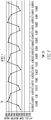
FIG. 3A is a graph of the waveform of a test signal input to a Rogowski coil disposed around a busbar of a circuit interrupter in accordance with an example embodiment of the disclosed concept; -
FIG. 3B is a graph of the waveform of a signal proportional to a temperature of the Rogowski coil after high pass or band pass filtering in accordance with an example embodiment of the disclosed concept; -
FIG. 4 is a graph of an output signal of a sampling component of a temperature measurement unit of an electronic trip unit of a circuit interrupter in accordance with an example embodiment of the disclosed concept; -
FIG. 5 is a flow chart of a method of estimating the temperature of a busbar in a circuit interrupter in accordance with an example embodiment of the disclosed concept. - Directional phrases used herein, such as, for example, left, right, front, back, top, bottom and derivatives thereof, relate to the orientation of the elements shown in the drawings and are not limiting upon the claims unless expressly recited therein.
-
FIG. 1 is a schematic diagram of acircuit interrupter 10 in accordance with an example embodiment of the disclosed concept andFIG. 2 is a schematic diagram of thecircuit interrupter 10 ofFIG. 1 shown in more detail in accordance with an example embodiment of the disclosed concept. Thecircuit interrupter 10 includes afirst terminal 11, asecond terminal 12, andseparable contacts 16. Thecircuit interrupter 10 further includes aline conductor 14, connecting the first andsecond terminals line conductor 14 may be comprised of one or more busbars. Theseparable contacts 16 are disposed along theline conductor 14 and tripping open theseparable contacts 16 stops current from flowing through theline conductor 14 from thefirst terminal 11 to thesecond terminal 12. Thecircuit interrupter 10 further includes anoperating mechanism 18 structured to trip open theseparable contacts 16. - The
circuit interrupter 10 further includes aRogowski coil 20 disposed around and structured to sense current flowing through the line conductor 14 (i.e., the busbars of the line conductor 14) of thecircuit interrupter 10. However, it will be appreciated that the Rogowski coil may also be employed to sense current flowing through a neutral conductor without departing from the scope of the disclosed concept. The current flowing through theline conductor 14 is expected to have a frequency of about 60 Hz, or the standard frequency of current provided by a utility. Thecircuit interrupter 10 further includes asignal conditioner 27 electrically connected to the Rogowskicoil 20, and acurrent measurement unit 26 used to determine the current flowing through theline conductor 14 based on the output of thesignal conditioner 27. Thesignal conditioner 27 may be analog or digital, and may perform amplification and/or integration functions. - The
circuit interrupter 10 further includes atest injector circuit 21 electrically connected to the Rogowskicoil 20. Thetest injector circuit 21 is structured to input a test signal to the Rogowskicoil 20 to be processed by atemperature measurement unit 28 in order to determine the temperature of the Rogowskicoil 20, which provides an estimate of the temperature of theline conductor 14. In some example embodiments, the test signal input to the Rogowskicoil 20 has a frequency substantially higher than the frequency of the current flowing through theline conductor 14. The higher frequency test signal is attenuated by the current measurement components such as thesignal conditioner 27 and thecurrent measurement unit 26 such that the test signal does not interfere with the measurement of current flowing through theline conductor 14. - The
circuit interrupter 10 further includes high pass or bandpass filter circuitry 22 electrically connected to the Rogowskicoil 20. The high pass or bandpass filter circuitry 22 is structured to receive the output of the Rogowskicoil 20, which is comprised of two component signals. The first component signal is proportional to the utility current flowing through theline conductor 14. The first component is induced in the Rogowskicoil 20 by the current flowing through theline conductor 14. The second component signal is the test signal input to the Rogowskicoil 20 by thetest injector circuit 21 and is proportional to the temperature of the Rogowskicoil 20. For example, as the temperature of the Rogowskicoil 20 increases or decreases, the resistance of the coils in the Rogowskicoil 20 changes. Such changes in resistance cause changes in the magnitude of the test signal. The high pass or bandpass filter circuitry 22 passes and amplifies the second component (i.e., the test input signal proportional to the temperature of the Rogowski coil) and attenuates the first component (i.e. the signal induced by the utility current flowing through the line conductor 14). - For example,
FIG. 3A shows a graph of awaveform 32 of a test signal generated by thetest injector circuit 21 and having a frequency of 4800 Hz that is input to the Rogowskicoil 20 of thecircuit interrupter 10.FIG. 3B shows a graph of awaveform 34 of a 4800 Hz signal output by the high pass or bandpass filter circuitry 22 after receiving the 4800 Hz output of the Rogowskicoil 20. The amplitude difference between theFIG. 3B graph ofwaveform 34 of the output of the high pass or bandpass filter circuitry 22 and theFIG. 3A graph oftest signal waveform 32 demonstrates that a test input signal with a properly chosen frequency will be passed by the high pass or bandpass filter circuitry 22, while the utility current signal will be attenuated. While 4800 Hz is an example of a frequency that a test signal and output of the high pass or band pass filter circuitry may have, it will be appreciated that other frequencies may be employed without departing from the scope of the disclosed concept. While 1.5 V is used inFIG. 3A as an example of an amplitude thatwaveform 32 may have and 100 mV is used inFIG. 3B as an example of an amplitude that waveform 34 may have, it will be appreciated that other voltage amplitudes may be employed without departing from the scope of the disclosed concept. - The
circuit interrupter 10 further includes anelectronic trip unit 29, which contains thetest injector circuit 21, the high pass or bandpass filter circuitry 22, thetemperature measurement unit 28, thesignal conditioner 27, and thecurrent measurement unit 26. Thecurrent measurement unit 26 receives the output of thesignal conditioner 27 and is structured to measure current flowing through theline conductor 14 based on the output of thesignal conditioner 27. Thetemperature measurement unit 28 receives the output of the high pass or bandpass filter circuitry 22 and is structured to estimate a temperature of theline conductor 14 based on the output of the high pass or bandpass filter circuitry 22. Theelectronic trip unit 29 is structured to detect faults in thecircuit interrupter 10 based on the sensed current. In response to detecting a fault, theelectronic trip unit 29 is structured to cause theoperating mechanism 18 to trip open theseparable contacts 16. Independently of the fault detection function, the temperature of theline conductor 14 estimated by thetemperature measurement unit 28 can be used to detect an overtemperature condition. An overtemperature condition may be indicative of loose wiring connections on the busbar. The detection of an overtemperature condition will cause an alarm to sound or produce another type of alert, indicating that the busbar wiring may need to be inspected. - The
temperature measurement unit 28 includes a sampling component 23 (shown inFIG. 2 ) structured to receive the output of the high pass or bandpass filter circuitry 22. Thesampling component 23 is structured to sample the output of the high pass or bandpass filter circuitry 22 at a sampling rate that results in a sampling output signal with substantially the same amplitude of the input signal to thesampling component 23. It will be appreciated by those having ordinary skill in the art that the sampling rate used by thesampling component 23 may be either greater than or less than the Nyquist rate. If a sampling rate less than the Nyquist rate is used, the sampling output signal will be an alias of the original test signal. In some example embodiments, using a sampling rate lower than the Nyquist rate can use less processing resources in theelectronic trip unit 29. The sampling rate can be chosen to be consistent with the rate already being used by the electronic trip unit to read currents and may result in aliasing of the high pass or bandpass filter circuitry 22 output. It will be appreciated by those having ordinary skill in the art that undersampling at a properly chosen rate will result in a sampling output signal that preserves the RMS amplitude information about the input signal to thesampling component 23. - For example, in
FIG. 3B , after a 4800 Hz test injection signal (shown inFIG. 2 ) is input to theRogowski coil 20 and the output of theRogowski coil 20 is input to the high pass or bandpass filter circuitry 22, a 4800Hz output signal 34 is output from the high pass or bandpass filter circuitry 22. InFIG. 4 , the 4800 Hz high pass or band passfilter output signal 34 is input to thesampling component 23, which undersamples signal 34 at a rate of 4000 Hz (shown inFIG. 2 ). This results in an 800 Hz samplingcomponent output signal 52 with an amplitude proportional to the test injection signal input waveform. While 4000 Hz is an example of a frequency at which a sampling component may sample and an example of a rate which may already be employed by the electronic trip unit to read currents, it will be appreciated that other frequencies may be employed by the sampling component without departing from the scope of the disclosed concept. While sampling a 4800 Hz high pass filter output signal at a rate of 4000 Hz results in an example 800 Hz sampling component output signal, it will be appreciated that sampling component output signals of other frequencies may be produced without departing from the scope of the disclosed concept, as the frequency of the sampling component output signal is dependent upon both the frequency of the high pass or band pass filter output signal and the sampling rate employed by the sampling component. - The
temperature measurement unit 28 further includes a frequency multiplier ormixer component 24 structured to receive the output of thesampling component 23. The multiplier orfrequency mixer component 24 is structured to either multiply the output of thesampling component 23 by sine and cosine signals of the same frequency as the sampling component output signal or frequency mix the output of thesampling component 23 in order to eliminate any unwanted signals of other frequencies that may be components of the output signal of the sampling component, such as harmonics of the utility current signal. It will be appreciated by those of ordinary skill in the art that unwanted signals and their harmonics can be removed by choosing a proper averaging time. For example, by averaging the output of thesampling component 23 over an integer multiple of the utility period and its harmonics, the net resultant signal at the unwanted utility frequency and its harmonic frequencies will be zero. - The
temperature sensing unit 26 further includes a frequency averagingfunction component 25 structured to remove all but the DC component from the output signal of the multiplier orfrequency mixer component 24. Thetemperature sensing unit 26 also includes a processor that computes the resistance of theRogowski coil 20 from the output of the frequency averagingfunction component 25 using the current through theRogowski coil 20, the ambient temperature, and the temperature coefficient of the windings of theRogowski coil 20. As the resistance of the windings of theRogowski coil 20 varies with temperature, the resistance is indicative of the temperature of the windings of theRogowski coil 20, which in turn is an estimate of the temperature of thebusbar 14. In an example embodiment, thetemperature measurement unit 28 may output an alarm when the estimated temperature (based on the resistance of the windings of the Rogowski coil 20) meets or exceeds a predetermined threshold level. -
FIG. 5 is a flowchart of a method of estimating a temperature of a busbar in accordance with an example embodiment of the disclosed concept. The method ofFIG. 5 may be employed, for example, with thecircuit interrupter 10 shown inFIGS. 1 and2 , and is described in conjunction with thecircuit interrupter 10 shown inFIGS. 1 and2 . However, it will be appreciated that the method may be employed in other devices as well without departing from the scope of the disclosed concept. - The method begins at 100 where the
Rogowski coil 20 disposed around thebusbar 14 of thecircuit interrupter 10 is provided. At 102, a test input signal is injected into theRogowski coil 20. At 104, an output of theRogowski coil 20 is received by the high pass or bandpass filter circuitry 22. At 106, the output of theRogowski coil 20 is filtered with the high pass or bandpass filter circuitry 22. At 108, an output of the high pass or bandpass filter circuitry 22 is received by thetemperature measurement unit 28. At 110, the temperature of thebusbar 14 is estimated with thetemperature measurement unit 28. - While specific embodiments of the disclosed concept have been described in detail, it will be appreciated by those skilled in the art that various modifications and alternatives to those details could be developed in light of the overall teachings of the disclosure. Accordingly, the particular arrangements disclosed are meant to be illustrative only and not limiting as to the scope of the disclosed concept which is to be given the full breadth of the claims appended and any and all equivalents thereof.
Claims (15)
- A circuit interrupter comprising:a busbar;a Rogowski coil disposed around the busbar and structured to sense current having a first frequency flowing through the busbar;a test injector circuit structured to input a test signal having a second frequency to the Rogowski coil;high pass or band pass filter circuitry structured to receive an output of the Rogowski coil, the output including a first component having the first frequency and being proportional to the current flowing through the busbar and a second component having the second frequency and being proportional to a temperature of the Rogowski coil, and to attenuate the first component of the output of the Rogowski coil; andan electronic trip unit including a temperature measurement unit structured to receive an output of the high pass or band pass filter circuitry and to estimate the temperature of the busbar based on the output of the high pass or band pass filter circuitry.
- The circuit interrupter of claim 1, wherein the second frequency is substantially higher than the first frequency.
- The circuit interrupter of claim 2, wherein the electronic trip unit includes current measurement circuitry structured to receive the output of the Rogowski coil and to attenuate the second component having the second frequency.
- The circuit interrupter of claim 1, wherein the temperature measurement unit includes a sampling component structured to sample the output of the high pass or band pass filter circuitry at a third frequency,
wherein an output of the sampling component has a fourth frequency,
wherein the temperature measurement unit includes a frequency multiplier or frequency mixer component structured to multiply or frequency mix the output of the sampling component by sines and cosines of the fourth frequency,
wherein the temperature measurement unit includes a frequency averaging function component structured to remove all but a DC component from an output of the frequency multiplier or frequency mixer component, and
wherein the temperature measurement unit includes a temperature calculation component structured to calculate the temperature of the Rogowski coil. - The circuit interrupter of claim 4, wherein the output of the sampling component is a signal with an amplitude proportional to an amplitude of the output of the high pass or band pass filter circuitry.
- The circuit interrupter of claim 1, further comprising:a first terminal;a second terminal;separable contacts moveable between a closed position and an open position, the first and second terminals being electrically disconnected from each other when the separable contacts are in the open position;an operating mechanism structured to open said separable contacts; andan actuator structured to cooperate with said operating mechanism to trip open said separable contacts.
- A method for estimating a temperature of a busbar in a circuit interrupter, the method comprising:providing a Rogowski coil disposed around the busbar and structured to sense current having a first frequency flowing through the busbar;injecting a test input signal having a second frequency into the Rogowski coil disposed around the busbar;receiving an output of the Rogowski coil with high pass or band pass filter circuitry, the output including a first component having the first frequency and being proportional to the current flowing through the busbar and a second component having the second frequency and being proportional to a temperature of the Rogowski coil;filtering the output of the Rogowski coil with the high pass or band pass filter circuitry and attenuating the first component of the output of the Rogowski coil;receiving an output of the high pass or band pass filter circuitry with a temperature measurement unit in an electronic trip unit of the circuit interrupter; andestimating the temperature of the busbar based on the output of the high pass or band pass filter circuitry.
- The method of claim 7, wherein the second frequency is substantially higher than the first frequency.
- The method of claim 7, wherein the electronic trip unit includes current measurement circuitry structured to receive the output of the Rogowski coil and to attenuate the second component having the second frequency.
- The method of claim 7, wherein the temperature measurement unit includes a sampling component structured to sample the output of the high pass or band pass filter circuitry at a third frequency,
wherein an output of the sampling component has a fourth frequency,
wherein the temperature measurement unit includes a frequency multiplier or frequency mixer component structured to multiply or frequency mix the output of the sampling component by sines and cosines of the fourth frequency,
wherein the temperature measurement unit includes a frequency averaging function component structured to remove all but a DC component from an output of the frequency multiplier or frequency mixer component, and
wherein the temperature measurement unit includes a temperature calculation component structured to calculate the temperature of the Rogowski coil. - The method of claim 10, wherein the output of the sampling component is a signal with an amplitude proportional to an amplitude of the output of the high pass or band pass filter circuitry.
- The method of claim 7, wherein the circuit interrupter includes:a first terminal;a second terminal;separable contacts moveable between a closed position and an open position, the first and second terminals being electrically disconnected from each other when the separable contacts are in the open position;an operating mechanism structured to open said separable contacts; andan actuator structured to cooperate with said operating mechanism to trip open said separable contacts.
- A circuit interrupter comprising:a busbar;a Rogowski coil disposed around the busbar and structured to sense current flowing through the busbar;a test injector circuit structured to input a test signal to the Rogowski coil;high pass or band pass filter circuitry structured to receive and high pass or band pass filter an output of the Rogowski coil; andan electronic trip unit including a temperature measurement unit structured to receive an output of the high pass or band pass filter circuitry and to estimate the temperature of the busbar based on the output of the high pass or band pass filter circuitry and a current measurement unit structured to receive an output of the Rogowski coil and estimate the current flowing through the busbar based on the output of the Rogowski coil.
- The circuit interrupter of claim 13, wherein the temperature measurement unit includes a sampling component structured to sample the output of the high pass or band pass filter circuitry,
wherein the temperature measurement unit includes a frequency multiplier or frequency mixer component structured to frequency multiply or frequency mix an output of the sampling component,
wherein the temperature measurement unit includes a frequency averaging function component structured to remove all but a DC component from an output of the frequency multiplier or frequency mixer component, and
wherein the temperature measurement unit includes a temperature calculation component structured to calculate the temperature of the Rogowski coil. - The circuit interrupter of claim 13, further comprising:a first terminal;a second terminal;separable contacts moveable between a closed position and an open position, the first and second terminals being electrically disconnected from each other when the separable contacts are in the open position;an operating mechanism structured to open said separable contacts; andan actuator structured to cooperate with said operating mechanism to trip open said separable contacts.
Applications Claiming Priority (1)
| Application Number | Priority Date | Filing Date | Title |
|---|---|---|---|
| US16/578,971 US11268987B2 (en) | 2019-09-23 | 2019-09-23 | Circuit interrupter and method of estimating a temperature of a busbar in a circuit interrupter |
Publications (2)
| Publication Number | Publication Date |
|---|---|
| EP3795966A1 true EP3795966A1 (en) | 2021-03-24 |
| EP3795966B1 EP3795966B1 (en) | 2023-10-25 |
Family
ID=72560381
Family Applications (1)
| Application Number | Title | Priority Date | Filing Date |
|---|---|---|---|
| EP20196551.4A Active EP3795966B1 (en) | 2019-09-23 | 2020-09-16 | Circuit interrupter and method of estimating a temperature of a busbar in a circuit interrupter |
Country Status (3)
| Country | Link |
|---|---|
| US (1) | US11268987B2 (en) |
| EP (1) | EP3795966B1 (en) |
| CN (1) | CN112542357B (en) |
Families Citing this family (2)
| Publication number | Priority date | Publication date | Assignee | Title |
|---|---|---|---|---|
| EP4125106A1 (en) * | 2021-07-27 | 2023-02-01 | Abb Schweiz Ag | Monitoring system for a low voltage, medium voltage, or high voltage circuit breaker |
| EP4530649A1 (en) * | 2023-09-26 | 2025-04-02 | General Electric Technology GmbH | Device and method for testing protection circuits in high-voltage gear/switchgear |
Citations (5)
| Publication number | Priority date | Publication date | Assignee | Title |
|---|---|---|---|---|
| US5461309A (en) * | 1992-09-10 | 1995-10-24 | Gec Alsthom T&D Sa | Device for measuring temperature using a Rogowski coil |
| JP2005003601A (en) * | 2003-06-13 | 2005-01-06 | Fuji Electric Holdings Co Ltd | Hybrid sensor |
| US20120105052A1 (en) * | 2010-10-29 | 2012-05-03 | Siemens Aktiengesellschaft | Method for measuring the current level of an alternating current |
| US20150372478A1 (en) * | 2014-06-24 | 2015-12-24 | Eaton Corporation | Thermal trip assembly and circuit interrutper including the same |
| US20170122995A1 (en) * | 2015-10-30 | 2017-05-04 | Landis+Gyr, Inc. | Method and arrangement for detecting a meter maintenance condition using winding resistance |
Family Cites Families (8)
| Publication number | Priority date | Publication date | Assignee | Title |
|---|---|---|---|---|
| US4855671A (en) * | 1983-04-13 | 1989-08-08 | Fernandes Roosevelt A | Electrical power line and substation monitoring apparatus |
| JP3410043B2 (en) * | 1999-04-28 | 2003-05-26 | 三菱電機株式会社 | Current detection system |
| US6678137B1 (en) * | 2000-08-04 | 2004-01-13 | General Electric Company | Temperature compensation circuit for an arc fault current interrupting circuit breaker |
| JP2004119926A (en) * | 2002-09-30 | 2004-04-15 | Toshiba Corp | Current transformer and current transformer system |
| US9410990B2 (en) * | 2013-03-08 | 2016-08-09 | Deere & Company | Method and sensor for sensing current in a conductor |
| US9520254B2 (en) * | 2014-06-24 | 2016-12-13 | Eaton Corporation | Circuit interrupter including thermal trip assembly and printed circuit board Rogowski coil |
| KR101623366B1 (en) * | 2015-07-03 | 2016-05-24 | (주)서전기전 | Self-diagnostic switch gear having history information, operation data and diagnostic information |
| JP6919447B2 (en) * | 2017-09-14 | 2021-08-18 | 株式会社デンソー | Reactor temperature estimation method |
-
2019
- 2019-09-23 US US16/578,971 patent/US11268987B2/en active Active
-
2020
- 2020-09-07 CN CN202010926115.9A patent/CN112542357B/en active Active
- 2020-09-16 EP EP20196551.4A patent/EP3795966B1/en active Active
Patent Citations (5)
| Publication number | Priority date | Publication date | Assignee | Title |
|---|---|---|---|---|
| US5461309A (en) * | 1992-09-10 | 1995-10-24 | Gec Alsthom T&D Sa | Device for measuring temperature using a Rogowski coil |
| JP2005003601A (en) * | 2003-06-13 | 2005-01-06 | Fuji Electric Holdings Co Ltd | Hybrid sensor |
| US20120105052A1 (en) * | 2010-10-29 | 2012-05-03 | Siemens Aktiengesellschaft | Method for measuring the current level of an alternating current |
| US20150372478A1 (en) * | 2014-06-24 | 2015-12-24 | Eaton Corporation | Thermal trip assembly and circuit interrutper including the same |
| US20170122995A1 (en) * | 2015-10-30 | 2017-05-04 | Landis+Gyr, Inc. | Method and arrangement for detecting a meter maintenance condition using winding resistance |
Also Published As
| Publication number | Publication date |
|---|---|
| EP3795966B1 (en) | 2023-10-25 |
| CN112542357B (en) | 2025-08-08 |
| US11268987B2 (en) | 2022-03-08 |
| CN112542357A (en) | 2021-03-23 |
| US20210088556A1 (en) | 2021-03-25 |
Similar Documents
| Publication | Publication Date | Title |
|---|---|---|
| US7638999B2 (en) | Protective relay device, system and methods for Rogowski coil sensors | |
| KR100299015B1 (en) | Ground fault and sputtering arc trip device of self-test circuit breaker | |
| CN101685130B (en) | Directional detection of a ground fault | |
| CN106415286B (en) | System and method for impulse ground fault detection and localization | |
| CN100427887C (en) | Transient overcurrent element for severe saturation current in power system | |
| US7944213B2 (en) | Ground fault detection device | |
| CN101208845B (en) | Fault current analyzer and device with fault current detection | |
| CN110967571B (en) | Method for diagnosing the cause of tripping of an electrical protection device, auxiliary device and electrical system | |
| US12387884B2 (en) | Circuit interrupting device having printed circuit board coils | |
| US20040264094A1 (en) | Protective control method and apparatus for power devices | |
| EP3795966B1 (en) | Circuit interrupter and method of estimating a temperature of a busbar in a circuit interrupter | |
| US20180159310A1 (en) | Arc fault circuit interrupter apparatus and methods using symmetrical component harmonic detection | |
| EP3560054A1 (en) | A method for detecting inrush and ct saturation and an inteligent electronic device therfor | |
| CN105359365B (en) | Method and apparatus for complex, universal ground fault protection in medium and high voltage power systems | |
| JP2002311061A (en) | Processor for electric power | |
| EP2681572B1 (en) | Method for adaptation of ground fault detection | |
| JP2011217588A (en) | Ground fault detection apparatus for electric circuit of non-grounded system and ground fault protective relay using the apparatus, and method of detecting ground fault | |
| US20250321292A1 (en) | Method to detect single-phase-to-ground faults in electric power systems | |
| JP5072084B2 (en) | Device for detecting resistance ground fault current | |
| CN100385761C (en) | Electronic trip device with phase reconfiguration function and circuit breaker including the trip device | |
| US8228103B2 (en) | Circuit breaker | |
| JP5190635B2 (en) | Device for detecting resistance ground fault current | |
| US6154687A (en) | Modified cosine filters | |
| US7724488B2 (en) | Method for controlling an electronic overcurrent trip for low-voltage circuit breakers | |
| JP5072085B2 (en) | Device for detecting resistance ground fault current |
Legal Events
| Date | Code | Title | Description |
|---|---|---|---|
| PUAI | Public reference made under article 153(3) epc to a published international application that has entered the european phase |
Free format text: ORIGINAL CODE: 0009012 |
|
| STAA | Information on the status of an ep patent application or granted ep patent |
Free format text: STATUS: REQUEST FOR EXAMINATION WAS MADE |
|
| 17P | Request for examination filed |
Effective date: 20200916 |
|
| AK | Designated contracting states |
Kind code of ref document: A1 Designated state(s): AL AT BE BG CH CY CZ DE DK EE ES FI FR GB GR HR HU IE IS IT LI LT LU LV MC MK MT NL NO PL PT RO RS SE SI SK SM TR |
|
| AX | Request for extension of the european patent |
Extension state: BA ME |
|
| GRAP | Despatch of communication of intention to grant a patent |
Free format text: ORIGINAL CODE: EPIDOSNIGR1 |
|
| STAA | Information on the status of an ep patent application or granted ep patent |
Free format text: STATUS: GRANT OF PATENT IS INTENDED |
|
| INTG | Intention to grant announced |
Effective date: 20230330 |
|
| GRAS | Grant fee paid |
Free format text: ORIGINAL CODE: EPIDOSNIGR3 |
|
| P01 | Opt-out of the competence of the unified patent court (upc) registered |
Effective date: 20230521 |
|
| GRAA | (expected) grant |
Free format text: ORIGINAL CODE: 0009210 |
|
| STAA | Information on the status of an ep patent application or granted ep patent |
Free format text: STATUS: THE PATENT HAS BEEN GRANTED |
|
| AK | Designated contracting states |
Kind code of ref document: B1 Designated state(s): AL AT BE BG CH CY CZ DE DK EE ES FI FR GB GR HR HU IE IS IT LI LT LU LV MC MK MT NL NO PL PT RO RS SE SI SK SM TR |
|
| REG | Reference to a national code |
Ref country code: GB Ref legal event code: FG4D |
|
| REG | Reference to a national code |
Ref country code: CH Ref legal event code: EP |
|
| REG | Reference to a national code |
Ref country code: DE Ref legal event code: R096 Ref document number: 602020019735 Country of ref document: DE |
|
| REG | Reference to a national code |
Ref country code: IE Ref legal event code: FG4D |
|
| REG | Reference to a national code |
Ref country code: LT Ref legal event code: MG9D |
|
| REG | Reference to a national code |
Ref country code: NL Ref legal event code: MP Effective date: 20231025 |
|
| REG | Reference to a national code |
Ref country code: AT Ref legal event code: MK05 Ref document number: 1625111 Country of ref document: AT Kind code of ref document: T Effective date: 20231025 |
|
| PG25 | Lapsed in a contracting state [announced via postgrant information from national office to epo] |
Ref country code: NL Free format text: LAPSE BECAUSE OF FAILURE TO SUBMIT A TRANSLATION OF THE DESCRIPTION OR TO PAY THE FEE WITHIN THE PRESCRIBED TIME-LIMIT Effective date: 20231025 |
|
| PG25 | Lapsed in a contracting state [announced via postgrant information from national office to epo] |
Ref country code: GR Free format text: LAPSE BECAUSE OF FAILURE TO SUBMIT A TRANSLATION OF THE DESCRIPTION OR TO PAY THE FEE WITHIN THE PRESCRIBED TIME-LIMIT Effective date: 20240126 |
|
| PG25 | Lapsed in a contracting state [announced via postgrant information from national office to epo] |
Ref country code: IS Free format text: LAPSE BECAUSE OF FAILURE TO SUBMIT A TRANSLATION OF THE DESCRIPTION OR TO PAY THE FEE WITHIN THE PRESCRIBED TIME-LIMIT Effective date: 20240225 |
|
| PG25 | Lapsed in a contracting state [announced via postgrant information from national office to epo] |
Ref country code: LT Free format text: LAPSE BECAUSE OF FAILURE TO SUBMIT A TRANSLATION OF THE DESCRIPTION OR TO PAY THE FEE WITHIN THE PRESCRIBED TIME-LIMIT Effective date: 20231025 |
|
| PG25 | Lapsed in a contracting state [announced via postgrant information from national office to epo] |
Ref country code: AT Free format text: LAPSE BECAUSE OF FAILURE TO SUBMIT A TRANSLATION OF THE DESCRIPTION OR TO PAY THE FEE WITHIN THE PRESCRIBED TIME-LIMIT Effective date: 20231025 |
|
| PG25 | Lapsed in a contracting state [announced via postgrant information from national office to epo] |
Ref country code: ES Free format text: LAPSE BECAUSE OF FAILURE TO SUBMIT A TRANSLATION OF THE DESCRIPTION OR TO PAY THE FEE WITHIN THE PRESCRIBED TIME-LIMIT Effective date: 20231025 |
|
| PG25 | Lapsed in a contracting state [announced via postgrant information from national office to epo] |
Ref country code: LT Free format text: LAPSE BECAUSE OF FAILURE TO SUBMIT A TRANSLATION OF THE DESCRIPTION OR TO PAY THE FEE WITHIN THE PRESCRIBED TIME-LIMIT Effective date: 20231025 Ref country code: IS Free format text: LAPSE BECAUSE OF FAILURE TO SUBMIT A TRANSLATION OF THE DESCRIPTION OR TO PAY THE FEE WITHIN THE PRESCRIBED TIME-LIMIT Effective date: 20240225 Ref country code: GR Free format text: LAPSE BECAUSE OF FAILURE TO SUBMIT A TRANSLATION OF THE DESCRIPTION OR TO PAY THE FEE WITHIN THE PRESCRIBED TIME-LIMIT Effective date: 20240126 Ref country code: ES Free format text: LAPSE BECAUSE OF FAILURE TO SUBMIT A TRANSLATION OF THE DESCRIPTION OR TO PAY THE FEE WITHIN THE PRESCRIBED TIME-LIMIT Effective date: 20231025 Ref country code: BG Free format text: LAPSE BECAUSE OF FAILURE TO SUBMIT A TRANSLATION OF THE DESCRIPTION OR TO PAY THE FEE WITHIN THE PRESCRIBED TIME-LIMIT Effective date: 20240125 Ref country code: AT Free format text: LAPSE BECAUSE OF FAILURE TO SUBMIT A TRANSLATION OF THE DESCRIPTION OR TO PAY THE FEE WITHIN THE PRESCRIBED TIME-LIMIT Effective date: 20231025 Ref country code: PT Free format text: LAPSE BECAUSE OF FAILURE TO SUBMIT A TRANSLATION OF THE DESCRIPTION OR TO PAY THE FEE WITHIN THE PRESCRIBED TIME-LIMIT Effective date: 20240226 |
|
| PG25 | Lapsed in a contracting state [announced via postgrant information from national office to epo] |
Ref country code: SE Free format text: LAPSE BECAUSE OF FAILURE TO SUBMIT A TRANSLATION OF THE DESCRIPTION OR TO PAY THE FEE WITHIN THE PRESCRIBED TIME-LIMIT Effective date: 20231025 Ref country code: RS Free format text: LAPSE BECAUSE OF FAILURE TO SUBMIT A TRANSLATION OF THE DESCRIPTION OR TO PAY THE FEE WITHIN THE PRESCRIBED TIME-LIMIT Effective date: 20231025 Ref country code: PL Free format text: LAPSE BECAUSE OF FAILURE TO SUBMIT A TRANSLATION OF THE DESCRIPTION OR TO PAY THE FEE WITHIN THE PRESCRIBED TIME-LIMIT Effective date: 20231025 Ref country code: NO Free format text: LAPSE BECAUSE OF FAILURE TO SUBMIT A TRANSLATION OF THE DESCRIPTION OR TO PAY THE FEE WITHIN THE PRESCRIBED TIME-LIMIT Effective date: 20240125 Ref country code: LV Free format text: LAPSE BECAUSE OF FAILURE TO SUBMIT A TRANSLATION OF THE DESCRIPTION OR TO PAY THE FEE WITHIN THE PRESCRIBED TIME-LIMIT Effective date: 20231025 Ref country code: HR Free format text: LAPSE BECAUSE OF FAILURE TO SUBMIT A TRANSLATION OF THE DESCRIPTION OR TO PAY THE FEE WITHIN THE PRESCRIBED TIME-LIMIT Effective date: 20231025 |
|
| PG25 | Lapsed in a contracting state [announced via postgrant information from national office to epo] |
Ref country code: DK Free format text: LAPSE BECAUSE OF FAILURE TO SUBMIT A TRANSLATION OF THE DESCRIPTION OR TO PAY THE FEE WITHIN THE PRESCRIBED TIME-LIMIT Effective date: 20231025 |
|
| PG25 | Lapsed in a contracting state [announced via postgrant information from national office to epo] |
Ref country code: CZ Free format text: LAPSE BECAUSE OF FAILURE TO SUBMIT A TRANSLATION OF THE DESCRIPTION OR TO PAY THE FEE WITHIN THE PRESCRIBED TIME-LIMIT Effective date: 20231025 |
|
| REG | Reference to a national code |
Ref country code: DE Ref legal event code: R097 Ref document number: 602020019735 Country of ref document: DE |
|
| PG25 | Lapsed in a contracting state [announced via postgrant information from national office to epo] |
Ref country code: SK Free format text: LAPSE BECAUSE OF FAILURE TO SUBMIT A TRANSLATION OF THE DESCRIPTION OR TO PAY THE FEE WITHIN THE PRESCRIBED TIME-LIMIT Effective date: 20231025 |
|
| PG25 | Lapsed in a contracting state [announced via postgrant information from national office to epo] |
Ref country code: SM Free format text: LAPSE BECAUSE OF FAILURE TO SUBMIT A TRANSLATION OF THE DESCRIPTION OR TO PAY THE FEE WITHIN THE PRESCRIBED TIME-LIMIT Effective date: 20231025 Ref country code: SK Free format text: LAPSE BECAUSE OF FAILURE TO SUBMIT A TRANSLATION OF THE DESCRIPTION OR TO PAY THE FEE WITHIN THE PRESCRIBED TIME-LIMIT Effective date: 20231025 Ref country code: RO Free format text: LAPSE BECAUSE OF FAILURE TO SUBMIT A TRANSLATION OF THE DESCRIPTION OR TO PAY THE FEE WITHIN THE PRESCRIBED TIME-LIMIT Effective date: 20231025 Ref country code: EE Free format text: LAPSE BECAUSE OF FAILURE TO SUBMIT A TRANSLATION OF THE DESCRIPTION OR TO PAY THE FEE WITHIN THE PRESCRIBED TIME-LIMIT Effective date: 20231025 Ref country code: DK Free format text: LAPSE BECAUSE OF FAILURE TO SUBMIT A TRANSLATION OF THE DESCRIPTION OR TO PAY THE FEE WITHIN THE PRESCRIBED TIME-LIMIT Effective date: 20231025 Ref country code: CZ Free format text: LAPSE BECAUSE OF FAILURE TO SUBMIT A TRANSLATION OF THE DESCRIPTION OR TO PAY THE FEE WITHIN THE PRESCRIBED TIME-LIMIT Effective date: 20231025 |
|
| PLBE | No opposition filed within time limit |
Free format text: ORIGINAL CODE: 0009261 |
|
| STAA | Information on the status of an ep patent application or granted ep patent |
Free format text: STATUS: NO OPPOSITION FILED WITHIN TIME LIMIT |
|
| 26N | No opposition filed |
Effective date: 20240726 |
|
| PG25 | Lapsed in a contracting state [announced via postgrant information from national office to epo] |
Ref country code: SI Free format text: LAPSE BECAUSE OF FAILURE TO SUBMIT A TRANSLATION OF THE DESCRIPTION OR TO PAY THE FEE WITHIN THE PRESCRIBED TIME-LIMIT Effective date: 20231025 |
|
| PG25 | Lapsed in a contracting state [announced via postgrant information from national office to epo] |
Ref country code: SI Free format text: LAPSE BECAUSE OF FAILURE TO SUBMIT A TRANSLATION OF THE DESCRIPTION OR TO PAY THE FEE WITHIN THE PRESCRIBED TIME-LIMIT Effective date: 20231025 |
|
| PG25 | Lapsed in a contracting state [announced via postgrant information from national office to epo] |
Ref country code: MC Free format text: LAPSE BECAUSE OF FAILURE TO SUBMIT A TRANSLATION OF THE DESCRIPTION OR TO PAY THE FEE WITHIN THE PRESCRIBED TIME-LIMIT Effective date: 20231025 |
|
| REG | Reference to a national code |
Ref country code: CH Ref legal event code: PL |
|
| PG25 | Lapsed in a contracting state [announced via postgrant information from national office to epo] |
Ref country code: LU Free format text: LAPSE BECAUSE OF NON-PAYMENT OF DUE FEES Effective date: 20240916 |
|
| GBPC | Gb: european patent ceased through non-payment of renewal fee |
Effective date: 20240916 |
|
| PG25 | Lapsed in a contracting state [announced via postgrant information from national office to epo] |
Ref country code: GB Free format text: LAPSE BECAUSE OF NON-PAYMENT OF DUE FEES Effective date: 20240916 |
|
| REG | Reference to a national code |
Ref country code: BE Ref legal event code: MM Effective date: 20240930 |
|
| PG25 | Lapsed in a contracting state [announced via postgrant information from national office to epo] |
Ref country code: BE Free format text: LAPSE BECAUSE OF NON-PAYMENT OF DUE FEES Effective date: 20240930 |
|
| PG25 | Lapsed in a contracting state [announced via postgrant information from national office to epo] |
Ref country code: CH Free format text: LAPSE BECAUSE OF NON-PAYMENT OF DUE FEES Effective date: 20240930 |
|
| PG25 | Lapsed in a contracting state [announced via postgrant information from national office to epo] |
Ref country code: IE Free format text: LAPSE BECAUSE OF NON-PAYMENT OF DUE FEES Effective date: 20240916 |
|
| PG25 | Lapsed in a contracting state [announced via postgrant information from national office to epo] |
Ref country code: FI Free format text: LAPSE BECAUSE OF FAILURE TO SUBMIT A TRANSLATION OF THE DESCRIPTION OR TO PAY THE FEE WITHIN THE PRESCRIBED TIME-LIMIT Effective date: 20231025 |
|
| PGFP | Annual fee paid to national office [announced via postgrant information from national office to epo] |
Ref country code: DE Payment date: 20250820 Year of fee payment: 6 |
|
| PGFP | Annual fee paid to national office [announced via postgrant information from national office to epo] |
Ref country code: IT Payment date: 20250820 Year of fee payment: 6 |
|
| PGFP | Annual fee paid to national office [announced via postgrant information from national office to epo] |
Ref country code: FR Payment date: 20250820 Year of fee payment: 6 |
|
| PG25 | Lapsed in a contracting state [announced via postgrant information from national office to epo] |
Ref country code: CY Free format text: LAPSE BECAUSE OF FAILURE TO SUBMIT A TRANSLATION OF THE DESCRIPTION OR TO PAY THE FEE WITHIN THE PRESCRIBED TIME-LIMIT; INVALID AB INITIO Effective date: 20200916 |
|
| PG25 | Lapsed in a contracting state [announced via postgrant information from national office to epo] |
Ref country code: HU Free format text: LAPSE BECAUSE OF FAILURE TO SUBMIT A TRANSLATION OF THE DESCRIPTION OR TO PAY THE FEE WITHIN THE PRESCRIBED TIME-LIMIT; INVALID AB INITIO Effective date: 20200916 |