EP3795957A1 - Load detector, method for manufacturing same, and load detecting system - Google Patents
Load detector, method for manufacturing same, and load detecting system Download PDFInfo
- Publication number
- EP3795957A1 EP3795957A1 EP19802962.1A EP19802962A EP3795957A1 EP 3795957 A1 EP3795957 A1 EP 3795957A1 EP 19802962 A EP19802962 A EP 19802962A EP 3795957 A1 EP3795957 A1 EP 3795957A1
- Authority
- EP
- European Patent Office
- Prior art keywords
- load
- load detector
- plate portion
- placing part
- placing
- Prior art date
- Legal status (The legal status is an assumption and is not a legal conclusion. Google has not performed a legal analysis and makes no representation as to the accuracy of the status listed.)
- Granted
Links
Images





Classifications
-
- G—PHYSICS
- G01—MEASURING; TESTING
- G01G—WEIGHING
- G01G19/00—Weighing apparatus or methods adapted for special purposes not provided for in the preceding groups
- G01G19/44—Weighing apparatus or methods adapted for special purposes not provided for in the preceding groups for weighing persons
- G01G19/445—Weighing apparatus or methods adapted for special purposes not provided for in the preceding groups for weighing persons in a horizontal position
-
- G—PHYSICS
- G01—MEASURING; TESTING
- G01L—MEASURING FORCE, STRESS, TORQUE, WORK, MECHANICAL POWER, MECHANICAL EFFICIENCY, OR FLUID PRESSURE
- G01L1/00—Measuring force or stress, in general
- G01L1/20—Measuring force or stress, in general by measuring variations in ohmic resistance of solid materials or of electrically-conductive fluids; by making use of electrokinetic cells, i.e. liquid-containing cells wherein an electrical potential is produced or varied upon the application of stress
- G01L1/22—Measuring force or stress, in general by measuring variations in ohmic resistance of solid materials or of electrically-conductive fluids; by making use of electrokinetic cells, i.e. liquid-containing cells wherein an electrical potential is produced or varied upon the application of stress using resistance strain gauges
-
- G—PHYSICS
- G01—MEASURING; TESTING
- G01G—WEIGHING
- G01G19/00—Weighing apparatus or methods adapted for special purposes not provided for in the preceding groups
- G01G19/44—Weighing apparatus or methods adapted for special purposes not provided for in the preceding groups for weighing persons
-
- A—HUMAN NECESSITIES
- A61—MEDICAL OR VETERINARY SCIENCE; HYGIENE
- A61B—DIAGNOSIS; SURGERY; IDENTIFICATION
- A61B5/00—Measuring for diagnostic purposes; Identification of persons
- A61B5/68—Arrangements of detecting, measuring or recording means, e.g. sensors, in relation to patient
- A61B5/6887—Arrangements of detecting, measuring or recording means, e.g. sensors, in relation to patient mounted on external non-worn devices, e.g. non-medical devices
- A61B5/6891—Furniture
-
- G—PHYSICS
- G01—MEASURING; TESTING
- G01G—WEIGHING
- G01G19/00—Weighing apparatus or methods adapted for special purposes not provided for in the preceding groups
- G01G19/52—Weighing apparatus combined with other objects, e.g. furniture
-
- G—PHYSICS
- G01—MEASURING; TESTING
- G01G—WEIGHING
- G01G21/00—Details of weighing apparatus
- G01G21/02—Arrangements of bearings
-
- G—PHYSICS
- G01—MEASURING; TESTING
- G01G—WEIGHING
- G01G21/00—Details of weighing apparatus
- G01G21/22—Weigh pans or other weighing receptacles; Weighing platforms
-
- G—PHYSICS
- G01—MEASURING; TESTING
- G01G—WEIGHING
- G01G3/00—Weighing apparatus characterised by the use of elastically-deformable members, e.g. spring balances
- G01G3/12—Weighing apparatus characterised by the use of elastically-deformable members, e.g. spring balances wherein the weighing element is in the form of a solid body stressed by pressure or tension during weighing
- G01G3/14—Weighing apparatus characterised by the use of elastically-deformable members, e.g. spring balances wherein the weighing element is in the form of a solid body stressed by pressure or tension during weighing measuring variations of electrical resistance
Definitions
- the present invention relates to a load detector, a method for manufacturing the load detector, and a load detecting system including the load detector.
- a load applied to a bed is detected to determine whether or not a patient or an inmate is present on the bed, and/or to obtain information such as a respiration rate of the patient or the like on the bed.
- a load detector for detecting load can be placed in various positions, for example under the support leg of the bed.
- Patent Literature 1 discloses a load detector including a placing (mounting) plate part integrally formed with a cantilever portion and a slope adjoining the placing part.
- Patent Literature 1 Japanese Patent No. 5143946 , specification.
- Beds used in hospitals and/or nursing care facilities are typically provided with casters to assist in moving the bed.
- the bed is heavy, it is difficult to say that the moving of the bed by using casters is easy, and in particular, it is physical labor and laborious work to place (mount) the caster provided on the leg of the bed on the placing plate part of the load detector such as disclosed in Patent Literature 1.
- An object of the present invention is to provide a load detector capable of easily placing a caster of a bed on a placing part.
- a load detector for detecting a load of a subject on a bed having a caster, the load detector including:
- the load detector according to the first aspect may further include a reinforcing portion fixed to a lower surface of the placing part.
- the placing part may be separated from the peripheral part by a slit formed in the plate portion.
- the peripheral part may have a frame-shape surrounding the placing part.
- the strain senser may be attached to a lower surface of the linking part.
- an upper surface of the placing part, an upper surface of the linking part, and an upper surface of the peripheral part may be flush with each other.
- a recess configured to restrict a movement of the caster may be provided in an upper surface of the placing part.
- an upper surface of the placing part may be a flat surface.
- the linking part may be a plurality of parts provided at equal intervals along a periphery of the placing part.
- the load detector according to the first aspect may further include a guide member including the slope portion and a support portion configured to support the plate portion.
- a manufacturing method for the load detector according to the first aspect including:
- a manufacturing method for the load detector according to the first aspect including:
- a load detecting system for detecting a load of a subject on a bed, the load detecting system comprising:
- a caster of a bed can be easily placed on the placing part.
- the load detector 100 of the first embodiment of the present invention will be described by exemplifying a situation in which a bed BD ( Fig. 6 ) is placed (mounted) on the load detector 100 and a load of a subject on the bed BD is detected.
- the load detector 100 mainly includes a plate portion 1 which is a square in plan view, and a guide portion 3 provided around the plate portion 1 and having a square frame shape in plan view.
- the guide portion 3 is installed on the floor surface (installation surface) F ( Fig. 4, Fig. 5 ), the plate portion 1 is supported by the guide portion 3 so that the plate portion 1 is arranged parallel to the floor F having a space between the plate portion 1 and the floor surface F.
- the height of the upper surface of the plate portion 1 from the floor F may be about 5mm to 15mm as an example, but is not limited thereto.
- the center of the plate portion 1 is assumed to be the center O of the plate portion 1 and the load detector 100.
- a direction extending along one side of the plate portion 1 is defined as an X direction, and a direction extending along another side orthogonal to the one side of the plate portion 1 is defined as a Y direction.
- the surface facing away from the floor F in a state that the load detector 100 is installed on the floor F is defined as the upper surfaces of the plate portion 1 and the guide portion 3
- the surface facing toward the floor F in a state that the load detector 100 is installed on the floor F is defined as the lower surfaces of the plate portion 1 and the guide portion 3.
- the plate portion 1 is a one-fold (monolithic) flat plate extending in the same plane (within one plane).
- the plate portion 1 can be formed of stainless-steel (SUS304, etc.), but is not limited thereto.
- Plate portion 1 is divided, by four slits S1, into a placing part (placing area) 11, linking parts (linking areas, connecting parts) 12, and a peripheral part (peripheral area) 13.
- the upper surfaces of the placing part 11, the linking parts 12, and the peripheral part 13 are flush with each other.
- Four slits S1 have the same shape to each other.
- One pair of the slits are provided on both sides in the X direction of the center O in line symmetrical about a straight line extending in the Y direction through the center O.
- the other pair of the slits are provided on both sides in the Y direction of the center O in line symmetrical about a straight line extending in the X direction through the center O.
- the four slits S1 are provided with four times (folds) rotational symmetry around the center O.
- Each of the four slits S1 includes a first part S11 extending linearly in the side direction (X direction or Y direction) of the plate portion 1, and second parts S12 extending from both ends of the first part S11 away from the center O along the diagonal direction of the plate portion 1.
- the distal end portion of the second part S12 is rounded so as not to cause breakage in the plate portion 1 when the deflection occurs in the linking part 12.
- the placing part 11 is a part (area), which is substantially square in plan view, defined at the center of the plate portion 1 by being separated (spaced) from the peripheral part 13 with the first parts S11 of the four slits S1.
- the center of the placing part 11 matches the center O of the plate portion 1 and the load detector 100.
- the reinforcing member (reinforcing portion) 2 is welded on the lower surface 11b ( Fig. 3 ) of the placing part 11.
- the reinforcing member 2 is provided to prevent or suppress deflection that may occur in the placing part 11 when the caster CT is placed on the upper surface 11a of the placing part 11.
- the reinforcing member 2 is a plate-like member that is adhered to the placing part 11 in parallel with the placing part 11, and has four substantially triangular cut-out portions h.
- the shape of the reinforcing member 2 is not limited thereto, and a member having various shapes such as a plate shape, a beam shape, or the like, which can prevent or suppress deflection that may occur in the placing part 11, can be used as the reinforcing member 2.
- the linking part 12 is a part (area) linking (connecting) the placing part 11 and the peripheral part 13.
- Four linking parts 12 in total are defined at four corners of the placing part 11, respectively, with four slits S1.
- Each of the linking parts 12 is an elongated part (area) defined by two opposing second parts S12 of two of the four slits S1 adjacent in circumferential direction around the center O.
- Each of the linking parts 12 extends along the diagonal direction of the plate portion 1 from the corner of the placing part 11 toward the peripheral part 13. In the longitudinal direction of the linking part 12, one end portion is continuous with the placing part 11, the other end portion is continuous with the peripheral part 13.
- strain gages G are adhered (stuck) on a lower surface 12b of each of the linking parts 12. Two of the four strain gages G are adhered in the vicinity of one end portion in the longitudinal direction of the linking part 12 and remaining two of the four strain gages G are adhered in the vicinity of the other end portion in the longitudinal direction of the linking part 12.
- the distance between the two strain gages adhered in the vicinity of one end portion in the longitudinal direction of the linking part 12 and the center in the longitudinal direction of the linking part 12 is equal to the distance between the two strain gages adhered in the vicinity of the other end portion in the longitudinal direction of the linking part 12 and the center in the longitudinal direction of the linking part 12.
- Two strain gages G adhered in the vicinity of one end portion of the linking part 12 are arranged so that the distances from the lateral center of the linking part 12 are equal to each other, and two strain gages G adhered in the vicinity of the other end portion of the linking part 12 are arranged so that the distances from the lateral center of the linking part 12 are equal to each other.
- strain gages G each adhered to each of the linking parts 12 are connected to each other by a wiring (not depicted) to construct a Wheatstone bridge circuit WS.
- the peripheral part 13 is a part (area) located outside of the four slits S1 with respect to the center O of the plate portion 1.
- the peripheral part 13 mainly guides the caster CT that have reached the plate portion 1 passing through the guide portion 3 to the placing part 11 smoothly.
- the peripheral part 13 is a part (area) having a frame shape surrounding the placing part 11 and four linking parts 12.
- the guide portion 3 includes a first guide portion 31 and a third guide portion 33 provided on both sides of the plate portion 1 in the X direction, and includes the second guide portion 32 and a fourth guide portion 34 provided on both sides of the plate portion 1 in the Y direction.
- the first guide portion 31 has a substantially triangular prism shape.
- One end surface 31c of the first guide portion 31 in the longitudinal direction is inclined 45 ° with respect to the longitudinal direction; and the other end surface 31d is inclined 45 ° with respect to the longitudinal direction and inclined 90 ° with respect to the end surface 31c. Therefore, the first guide portion 31 is trapezoidal in plan view ( Fig. 2 ).
- the cross section, of the first guide portion 31, orthogonal to the longitudinal direction thereof is substantially right-angled triangle ( Fig. 4 ).
- the upper surface of the first guide portion 31 defining the oblique side in the cross section is a first slope SL1 for guiding the caster CT of the bed-BD onto the plate portion 1. Further, the upper end portion of the first slope SL1 is provided with a support groove g for supporting the plate portion 1.
- the second guide portion 32 has the same shape as the first guide portion 31.
- the upper surface of the second guide portion 32 is a second slope SL2.
- the third guide portion 33 has substantially the same shape as the first guide portion 31.
- the upper surface of the third guide portion 33 is a third slope SL3.
- a connector attaching portion 331 having a rectangular parallelepiped shape raised above the third slope SL3 is provided at one end of the third guide portion 33 in the longitudinal direction.
- a connector C for connecting the load detector 100 to a power supply and the data logger outside the load detector 100 is provided on the outer surface of the connector attaching portion 331.
- wire accommodation channel 332 is provided (recessed) on the lower surface 33b ( Fig. 3 ) of the third guide portion 33.
- the fourth guide portion 34 has substantially the same shape as the first guide portion 31.
- the upper surface of the fourth guide portion 34 is a fourth slope SL4.
- the end surface 34c ( Fig. 2 ) at one end of the fourth guide portion 34 in the longitudinal direction is orthogonal to the longitudinal direction.
- the first guide portion 31, the second guide portion 32, the third guide portion 33, and the fourth guide portion 34 are arranged in this order, in the circumferential direction around the center O, so as to surround the plate portion 1.
- An edge of the plate portion at one side in the X-direction is disposed in the support groove g of the first guide portion 31 and fixed to the first guide portion 31 by a screw (not depicted).
- An edge of the plate portion at the other side in the X-direction is disposed in the support groove g of the third guide portion 33 and fixed to the third guide portion 33 by a screw (not depicted).
- an edge of the plate portion 1 at one side in the Y-direction is disposed in the support groove g of the second guide portion 32 and fixed to the second guide portion 32 by a screw (not depicted); and an edge of the plate portion at the other side in the Y-direction is disposed in the support groove g of the fourth guide portion 34 and fixed to the fourth guide portion 34 by a screw (not depicted).
- the wire connects the connector C and each of the Wheatstone bridge circuits WS through the wire accommodation channel 332.
- a summing unit (summing circuit) 4 for summing the output of each of the Wheatstone bridge circuits WS, a wiring (not depicted) for connecting each of the Wheatstone bridge circuits WS and the summing unit 4, and a wiring (not depicted) for connecting the summing unit 4 and the connector C through the wire accommodation channel 332.
- the caster CT of the bed BD is placed on the placing part 11 of the plate portion 1. Specifically, the caster CT is climbed onto the plate portion 1 through any of the slopes SL1 to SL4, and then placed on the placing part 11 via the peripheral part 13.
- the other three casters CT included in the bed BD are respectively placed on the other three load detectors 100.
- the load of the subject on the bed BD is applied to the placing part 11 via the leg BL and the caster CT of the bed BD. With this, deflection occurs in each of the four linking parts 12 extending between the placing part 11 and the peripheral part 13 fixed to the guide portion 3 so as to change the resistance value in each of sixteen strain gages G adhered to the four linking parts 12.
- the change in the resistance values of the sixteen strain gages G are output as changes in the output voltages of the four Wheatstone bridges WS. Then, the changes in the output voltages of the four Wheatstone bridges WS are summed in the summing unit 4, and the load of the subject S is obtained based on the obtained sum value.
- the load detector 100 of the embodiment has slopes SL1, SL3 facing each other to sandwich the placing part 11, on which the caster CT of the bed BD is to be placed, in the X direction, and slopes SL2, SL4 facing each other to sandwich the placing part 11 in the Y direction. Therefore, the caster CT of the bed BD can be easily placed on the placing part 11 from substantially the entire area around the placing part 11 via at least one of the slopes SL to SL4.
- the four casters CT of the bed BD can be placed on the placing parts 11 of the four load detectors 100 simultaneously and quickly from various directions (see arrows a1, a2, a3, and a4 in Fig. 7 ).
- the slope SL1 to SL4 of the guide portion 3 is provided on substantially the entire area around the placing part 11 onto which the caster CT of the bed BD is placed, and thus the caster CT placed on the placing part 11 can be moved easily onto the floor F.
- the direction for moving the caster CT from the placing part onto the floor surface is specified by the structure of the load detector in a limited manner, and the direction (traveling direction) of the caster CT on the placing part does not coincide with the specified direction, it is necessary to adjust the traveling direction of the caster CT by, for example, touching the caster CT directly by hand such that the travelling direction matches the specified direction, while the caster CT remains stationary on the placing part.
- the load detector 100 of this embodiment can be moved from the placing part 11 to the floor F by moving the caster CT in various directions, there is no such trouble.
- the load detector 100 of the embodiment has a structure as follows. That is, the plate portion 1 which has flat plate shape and in which the placing part 11, the linking parts 12, and the peripheral part 13 are formed is supported by the guide portion 3. Thus, the distance between the placing part 11 and the floor surface F (the height of the placing part 11) is small. Therefore, even when the bed BD is placed on the placing part 11, the distance between the upper surface BU ( Fig. 6 ) of the bed BD and the floor surface F (the height of the upper surface BU) does not change greatly.
- the height of the upper surface BU of the bed BD is optimized in advance to a height suitable for performing a medical action and/or a care-giving action on a patient, a care-receiver, and the like on the bed, it is advantageous that the bed can be used without greatly changing the height of the upper surface BU. Further, since the distance between the placing part 11 and the floor surface F (the height of the placing part 11) is small, it does not require a large force to lift the caster CT onto the placing part 11 through the slope SL to SL4.
- the placing part 11 and the linking parts 12 are formed in the plate portion 1 having the flat plate shape, and thus, any wall portion or load cell or the like does not exist around the placing part 11. Therefore, even when any cover is provided for the caster CT of the bed BD or any medical device or wiring or the like is fixed to the leg BL of the bed BD, there is no fear that a part of the load detector 100 contacts such cover, device or the like. Thus, casters (beds) of various forms can be placed on the placing part 11 in a state that accurate load detection is capable.
- a reinforcing member 2 for preventing or suppressing the deflection of the plate portion 1 is provided on the lower surface of the placing part 11 of the plate portion 1.
- the amount of deflection occurring in the linking part 12 around the placing part 11 is optimized.
- a peripheral part 13, and a placing part 11 which is spaced from the peripheral part 13 by the slit S1 is formed in the plate portion 1 having the flat plate shape. Therefore, the caster CT having reached the plate portion 1 via any one of the slopes SL to SL4 can smoothly move onto the placing part 11 through the peripheral part 13 and the slit S1 without crossing any large gap that may impact the bed BD and/or a subject on the bed BD. Further, since the peripheral portion 13 has a frame shape surrounding the placing part 11, the caster CT can move smoothly onto the placing part 11 through the peripheral part 13 and the slit S1 in each of cases where the caster CT has reached the plate portion 1 via slopes SL1 to SL4.
- the placing part 11, the linking parts 12, and the peripheral part 13 are flush with each other, and thus, the caster CT having reached the peripheral part 13 can move smoothly onto the placing part 11.
- the upper surface of the plate portion 1 including the placing part 11 is a flat surface, and a wall portion or the like for stopping the caster CT by abutting the caster CT is not provided. Therefore, the caster CT having reached the placing part 11 is placed on the placing part 11 of the bed BD without causing a collision with the wall portion or the like that impacts the bed BD and/or a subject on the bed BD.
- Such smooth movement and stop of the caster CT are particularly preferable in the case where an emergency patient, a care-receiver with weakness, or the like exists on the bed BD.
- the linking parts 12 are provided at the four corners of the rectangular placing part 11.
- the reason is as follows. That is, when a subject (caster CT) is placed at a position deviated from the center O of the plate portion 1, positional deviation error may occur in output of each of the Wheatstone bridges WS of four linking parts 12.
- positional deviation error may occur in output of each of the Wheatstone bridges WS of four linking parts 12.
- the deviation error in each of the four Wheatstone bridges WS is canceled out in the sum of the outputs of the Wheatstone bridges WS of four linking parts 12.
- the methods of providing the placing part 11, the linking part 12, and the peripheral part 13 in the plate portion 1 are not limited to the above-described aspect, and various aspects may be used.
- the slits S2 each including the arc-shaped first part S21, and the second portions S22 linearly extending from both ends of the first portion S21 may be formed so as to have three times (folds) rotational symmetry about the center O of the plate portion 1.
- a substantially circular placing part 11 having the center O as the center is defined at the central portion of the plate portion 1 by the first parts S21 of the slits S2.
- three linking parts 12 each having an elongated shape are defined by second parts S22 of the slits S2 at three parts around the placing part 11 at equal intervals in the circumferential direction so as to extend from the placing part 11 in the radial direction of the placing part 11.
- part other than the placing part 11 and the linking parts 12 is a peripheral part 13.
- the placing part 11 is positioned inside relative to the peripheral part 13 having a frame shape, and is surrounded by the peripheral part 13. Further, the placing part 11 is separated from the peripheral part 13 by the slit S2.
- the number of linking parts 12 partitioned around the placing part 11 is not limited to four or three, and may be any number. Specifically, for example, the number of linking parts 12 may be eight or six.
- a pair of slits S3 each having substantially L-shape including a first part S31 extending linearly in the Y direction and a second portion S32 extending linearly in the X direction may be formed in line symmetry relative to a segment extending in the X direction through the center O.
- the placing part 11 is defined in an area located on one side in the X-direction of the first portion S31 of the slit S3, and elongated linking part 12 is defined between the second portions S32 of the pair of slits S3.
- a part other than the placing part 11 and the linking part 12 is a peripheral part 13.
- the part of the outer periphery of the placing part 11 facing the slope SL1, SL2, SL4 is configured such that it is separated from the slope SL1, SL2, SL4 with a gap.
- the caster CT introduced onto the placing part 11 via the slope SL1, SL2, or SL4 is placed on the placing part 11 without passing through the peripheral part 13.
- the placing part 11 is provided inside relative to the peripheral part 13 so as to be separated from the peripheral part.
- “inside relative to the peripheral part” means a region within the plate portion located on the center side of the plate portion with respect to the peripheral part.
- the linking part 12 has an elongated shape, and specifically, is a rectangular shape. However, it is not limited thereto.
- the linking part 12 can be any shape as long as deflection occurs in the linking part 12 when the caster CT is placed on the placing part 11, and load can be detected via the strain gage G adhered to the linking part 12.
- the upper surfaces of the placing part 11, the linking parts 12, and the peripheral part 13 of the plate portion 1 are flush with each other.
- the linking parts 12 may be inclined downward from the peripheral part 13 toward the placing part 11, and the upper surface of the placing part 11 may be placed lower position compared to the upper surface of the peripheral part 13.
- the upper surface 11a of the placing part 11 is a flat surface.
- a recess (sunken part, concave part) R for restricting (regulating) move of the caster CT may be provided on the upper surface 11a of the placing part 11.
- the recess R may be a recess of rectangular in plan view, having a flat bottom Rb of rectangular in plan view and slopes Rs extending from the bottom Rb on both sides in the X and Y directions.
- the recess R may be a recess of circular in plan view, having a flat bottom Rb of circular in plan view and slope Rs surrounding the bottom Rb.
- the recess R may be of any shape as long as the recess R can restrict move of the caster.
- the caster CT mounted on the placing part 11 is fitted into the recess R, and move of the caster CT is restricted.
- the center of the bottom Rb may coincide with the center O of the plate portion 1.
- move of the caster CT fitted into the recess R is restricted in a state that the caster CT is aligned with the center O of the plate portion 1 and thus more accurate measurement is possible.
- the reinforcing member 2 for preventing or suppressing the deflection of the placing part 11 is fixed to the lower surface 11b of the placing part 11, but the reinforcing member 2 may be omitted.
- the four-gage method in which four strain gages G are adhered to each of the linking parts 12 of the plate portion 1 to construct the Wheatstone bridge WS is applied.
- the one-gage method or two-gage method may be used to adhere one or two strain gage(s) to the linking part 12.
- any strain detector capable of detecting strain occurred in the linking part 12 can be used. These are collectively referred to as strain sensor(s).
- one of the slopes SL1 to SL4 of the guide portion 3 is provided on substantially the entire area, of the periphery of the plate portion 1, except for the portion where the connector attaching portion 331 is provided.
- the load detector may be configured such that no slope is formed in the vicinities of corners of the plate portion 1 by allowing each of the first guide portion 31 to fourth guide portion 34 to have end surfaces in the longitudinal direction orthogonal to the longitudinal direction.
- the caster CT can be easily mounted on the placing part 11 from both sides in the X direction and both sides in the Y direction of the placing part 11.
- the load detector may be configured such that slopes are formed in the entire area around the placing part 11, by making the third guide portion 33 and the fourth guide portion 34 have the same shape as the first guide portion 31.
- power supply to the load detector 100 and output extraction may be achieved wirelessly, for example.
- power supply to the load detector 100 and output extraction may be achieved via a wiring extending downwardly from the load detector 100 and inside the floor F.
- the guide portion 3 including the slopes SL1 to SL4 supports the plate portion 1 (i.e., a support portion for supporting the plate portion, and the slope is formed as an integral guide portion).
- the plate portion 1 i.e., a support portion for supporting the plate portion, and the slope is formed as an integral guide portion.
- the support portion supporting the plate portion 1 and the slope for guiding the caster CT to the plate portion 1 may be separate members.
- plate-shaped slopes separated from the frame-shaped support portion may be attached to the upper surface of the plate portion 1 at four sides of the plate portion 1 so as to construct the slopes for guiding the caster CT on the floor F to the placing part 11.
- the slope itself may be a support for supporting the plate portion.
- the upper end of the plate-shaped slope is fixed to the outer periphery of the plate portion 1 so as to support the plate portion 1 by the slope.
- the plan view shape of the plate portion 1 is square, the plan view shape of the guide portion 3 is a square frame shape.
- the plan view shape of the plate portion 1 may be a rectangular, and the plan view shape of the guide portion 3 may be a rectangular frame shape.
- a configuration including a plate portion 201 of circular in plan view, and a guide portion 203 of annular in plan view can be adopted.
- the plate portion 201 is divided into circular placing part 211, four linking parts 212 of an elongated shape, and substantially annular peripheral portion 213 by four slits S201 provided in four times rotational symmetry about the center O of the plate portion 201.
- a slope SL located in substantially entire area in circumferential direction of the plate portion 201 and a connector attaching portion 2031 formed at a position where there is no slope SL is formed.
- the connector C is attached to the connector attaching portion 2031.
- the slopes SL exist on both sides of the plate portion 201 in each of two radial directions perpendicular to each other, and thus it can be regarded that at least two pairs of slopes are provided on both sides in the X direction and on both sides in the Y direction of the plate portion 201.
- the load detectors of the first embodiment and the modified examples can also be used to detect load of a subject on a stretcher or a delivery table.
- bed includes equipment, other than bed, which is used in medical facilities and/or nursing facilities and which is configured such that a patient and/or a care-receiver lies on the equipment, such as a stretcher, a delivery table, and the like.
- a plate portion 1 is obtained by cutting a plate material of stainless steel in a square shape. Then, four slits S1 is formed in the plate portion 1 to define the placing part 11, the linking parts 12, and the peripheral part 13 in the plate portion 1. Further, the first guide member 31 to the fourth guide member 34 for constructing the guide portion 3 is prepared by casting or the like.
- the reinforcing member 2 is fixed to the lower surface 11b of the placing part 11 by welding, and four strain gages G are adhered to the lower surface 12b of each of four linking parts 12.
- the strain gage unit in which four strain gages G are arranged on one sheet at a predetermined positional relationship may be used.
- the outer peripheral portion of the plate portion 1 is disposed in the support grooves g of the first guide portion 31 to the fourth guide portion 34, and the plate portion 1 is fixed to the first guide portion 31 to the fourth guide portion 34 by fasteners such as screws.
- each of the four linking parts 12 four strain gages are connected by wiring to construct the Wheatstone bridge WG, the summing unit 4 and the connector C is provided on the load detector 100, and wiring for connecting them is applied.
- a structure corresponding to the plate portion 1 having four slits S1 and the reinforcing member 2 fixed to the placing part 11 may be integrally molded by casting.
- regions (areas) corresponding to the back surfaces 12b of the four linking parts 12 in the structure are cut or ground to reduce the surface roughness of the regions and to adjust the thickness of the linking parts 12. Those are performed for adhering the strain gages G to the linking parts 12 satisfactorily, and for increasing measurement accuracy of the load detector 100 by making thicknesses of the four linking parts 12 equal to each other.
- a structure corresponding to the plate portion 1 having four slits S and the guide portion 3 may be integrally formed by casting. Again, after the structure is obtained by casting, regions corresponding to the back surfaces 12b of the four linking parts 12 in the structure are cut or ground to reduce the surface roughness of the regions and to adjust the thickness of the linking parts 12. Note that, the integral molding (solid casting) may be performed while further including a structure corresponding to the reinforcing member 2.
- the load detecting systems 500 of the second embodiment will be explained with reference to Fig. 12 .
- the load detecting system 500 mainly includes four load detectors 100 and a controller CONT.
- the four load detectors 100 and the controller CONT are connected by wiring.
- the four load detectors 100 are arranged on the floor F with a positional relationship corresponding to the four casters CT of the bed BD ( Fig. 7 ).
- the bed BD is then moved in any direction to place the bed BD on the four load detectors 100 via any one of the slopes SL1 to SL4.
- each of the four load detectors 100 detects a portion of the load of the subject on the bed BD applied via the leg BL of the bed BD.
- a controller CONT connected to the four load detectors 100 sums the outputs from the four load detectors 100 to obtain the load value of the subject on the bed BD.
- the load detecting system 500 of the embodiment uses the load detector 100 of the first embodiment, it is possible to obtain the same effect as the load detector 100 of the first embodiment.
- the four casters CT of the bed BD can be placed on the placing parts 11 of the four load detectors 100 simultaneously and quickly from various directions.
- the load detector of the present invention casters of beds can be easily placed on a placing part. Therefore, when the load detector is used in hospitals, nursing facilities, or the like, it is possible to easily and accurately arrange the bed on the load detector even in a situation where there is no space margin or time margin, thereby contributing to improvement in the quality of medical care or nursing care.
Landscapes
- Physics & Mathematics (AREA)
- General Physics & Mathematics (AREA)
- Health & Medical Sciences (AREA)
- Life Sciences & Earth Sciences (AREA)
- Heart & Thoracic Surgery (AREA)
- Surgery (AREA)
- Engineering & Computer Science (AREA)
- Biomedical Technology (AREA)
- Biophysics (AREA)
- Medical Informatics (AREA)
- Molecular Biology (AREA)
- Pathology (AREA)
- Animal Behavior & Ethology (AREA)
- General Health & Medical Sciences (AREA)
- Public Health (AREA)
- Veterinary Medicine (AREA)
- Invalid Beds And Related Equipment (AREA)
- Measurement Of Radiation (AREA)
Abstract
Description
- The present invention relates to a load detector, a method for manufacturing the load detector, and a load detecting system including the load detector.
- In hospitals, nursing facilities, or the like, a load applied to a bed is detected to determine whether or not a patient or an inmate is present on the bed, and/or to obtain information such as a respiration rate of the patient or the like on the bed. A load detector for detecting load can be placed in various positions, for example under the support leg of the bed.
-
Patent Literature 1 discloses a load detector including a placing (mounting) plate part integrally formed with a cantilever portion and a slope adjoining the placing part. - Patent Literature 1: Japanese Patent No.
5143946 - Beds used in hospitals and/or nursing care facilities are typically provided with casters to assist in moving the bed. However, since the bed is heavy, it is difficult to say that the moving of the bed by using casters is easy, and in particular, it is physical labor and laborious work to place (mount) the caster provided on the leg of the bed on the placing plate part of the load detector such as disclosed in
Patent Literature 1. - An object of the present invention is to provide a load detector capable of easily placing a caster of a bed on a placing part.
- According to a first aspect of the present invention, there is provided a load detector for detecting a load of a subject on a bed having a caster, the load detector including:
- a plate portion which is one-fold and which is to be supported above an installation surface, on which the load detector is installed, separately from the installation surface; and
- a slope portion which is provided around the plate portion and which is inclined relative to a surface of the plate portion so as to extend between the surface of the plate portion and the installation surface, wherein
- the plate portion includes:
- a peripheral part;
- a placing part on which the caster is to be placed, and which is provided inside relative to the peripheral part separately from the peripheral part; and
- a linking part which links the placing part and the peripheral part,
- the load detector further comprising a strain sensor attached to the linking part,
- wherein the slope portion includes at least two pairs of slopes each including a pair of slopes opposed to each other such that the placing part is interposed between the pair of slopes.
- The load detector according to the first aspect may further include a reinforcing portion fixed to a lower surface of the placing part.
- In the load detector according to the first aspect, the placing part may be separated from the peripheral part by a slit formed in the plate portion.
- In the load detector according to the first aspect, the peripheral part may have a frame-shape surrounding the placing part.
- In the load detector according to the first aspect, the strain senser may be attached to a lower surface of the linking part.
- In the load detector according to the first aspect, an upper surface of the placing part, an upper surface of the linking part, and an upper surface of the peripheral part may be flush with each other.
- In the load detector according to the first aspect, a recess configured to restrict a movement of the caster may be provided in an upper surface of the placing part.
- In the load detector according to the first aspect, an upper surface of the placing part may be a flat surface.
- In the load detector according to the first aspect, the linking part may be a plurality of parts provided at equal intervals along a periphery of the placing part.
- The load detector according to the first aspect may further include a guide member including the slope portion and a support portion configured to support the plate portion.
- According to a second aspect of the present invention, there is provided a manufacturing method for the load detector according to the first aspect, the method including:
- casting a member which is one-fold and which includes the plate portion and the slope portion;
- cutting or grinding an area of the member corresponding to a lower surface of the linking part; and
- attaching the strain sensor to the area which has been cut or ground.
- According to a third aspect of the present invention, there is provided a manufacturing method for the load detector according to the first aspect, the method including:
- casting a member which is one-fold and which includes the plate portion and the reinforcing portion;
- cutting or grinding an area of the member corresponding to a lower surface of the linking part; and
- attaching the strain sensor to the area which has been cut or ground.
- According to a fourth aspect of the present invention, there is provided a load detecting system for detecting a load of a subject on a bed, the load detecting system comprising:
- a plurality of load detectors; and
- a controller which is connected to the plurality of load detectors, and which is configured to obtain the load of the subject based on outputs of the plurality of load detectors, wherein
- each of the plurality of load detectors is the load detector according to the first aspect.
- According to the load detector of an aspect of the present invention, a caster of a bed can be easily placed on the placing part.
-
-
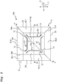
Fig. 1 is a perspective view of a load detector according to the first embodiment of the present invention. -
Fig. 2 is a top view of the load detector according to the first embodiment of the present invention. -
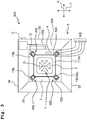
Fig. 3 is a bottom view of the load detector according to the first embodiment of the present invention. -
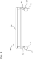
Fig. 4 is a cross-sectional view along line IV-IV ofFig. 2 . -
Fig. 5 is a cross-sectional view along line V-V ofFig. 2 . -
Fig. 6 depicts an example of a bed to be place on a load detector. -
Fig. 7 is an illustrative view illustrating various aspects in which four casters of the bed are placed simultaneously on four load detectors. -
Fig. 8(a) depicts a plate portion of a modified example in which a placing part, a linking part, and a peripheral part are defined.Fig. 8(b) depicts a plate portion of another modified example in which a placing part, a linking part, and a peripheral part are defined. -
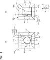
Fig. 9(a) depicts an example of a recess that can be provided in the placing part, andFig. 9(b) depicts another example of a recess that can be provided in the placing part. -
Fig. 10 (a) is a plan view depicting a modified example of a guide portion, andFig. 10(b) is a plan view depicting another modified example of the guide portion. -
Fig. 11(a) is a top view of a load detector of a modified example, andFig. 11(b) is a side view of the load detector of the modified example. -
Fig. 12 is a schematic view depicting a configuration of a load detecting system according to a second embodiment of the present invention. - The
load detector 100 of the first embodiment of the present invention will be described by exemplifying a situation in which a bed BD (Fig. 6 ) is placed (mounted) on theload detector 100 and a load of a subject on the bed BD is detected. - As depicted in
Fig. 1 ,Fig. 2 , andFig. 3 , theload detector 100 mainly includes aplate portion 1 which is a square in plan view, and aguide portion 3 provided around theplate portion 1 and having a square frame shape in plan view. When using theload detector 100, theguide portion 3 is installed on the floor surface (installation surface) F (Fig. 4, Fig. 5 ), theplate portion 1 is supported by theguide portion 3 so that theplate portion 1 is arranged parallel to the floor F having a space between theplate portion 1 and the floor surface F. In a state that theload detector 100 is arranged on the floor F, the height of the upper surface of theplate portion 1 from the floor F may be about 5mm to 15mm as an example, but is not limited thereto. - In the following description, the center of the
plate portion 1 is assumed to be the center O of theplate portion 1 and theload detector 100. A direction extending along one side of theplate portion 1 is defined as an X direction, and a direction extending along another side orthogonal to the one side of theplate portion 1 is defined as a Y direction. The surface facing away from the floor F in a state that theload detector 100 is installed on the floor F, is defined as the upper surfaces of theplate portion 1 and theguide portion 3, the surface facing toward the floor F in a state that theload detector 100 is installed on the floor F, is defined as the lower surfaces of theplate portion 1 and theguide portion 3. - The
plate portion 1 is a one-fold (monolithic) flat plate extending in the same plane (within one plane). Theplate portion 1 can be formed of stainless-steel (SUS304, etc.), but is not limited thereto.Plate portion 1 is divided, by four slits S1, into a placing part (placing area) 11, linking parts (linking areas, connecting parts) 12, and a peripheral part (peripheral area) 13. The upper surfaces of the placingpart 11, the linkingparts 12, and theperipheral part 13 are flush with each other. - Four slits S1 have the same shape to each other. One pair of the slits are provided on both sides in the X direction of the center O in line symmetrical about a straight line extending in the Y direction through the center O. The other pair of the slits are provided on both sides in the Y direction of the center O in line symmetrical about a straight line extending in the X direction through the center O. In other words, the four slits S1 are provided with four times (folds) rotational symmetry around the center O.
- Each of the four slits S1 includes a first part S11 extending linearly in the side direction (X direction or Y direction) of the
plate portion 1, and second parts S12 extending from both ends of the first part S11 away from the center O along the diagonal direction of theplate portion 1. The distal end portion of the second part S12 is rounded so as not to cause breakage in theplate portion 1 when the deflection occurs in the linkingpart 12. - The placing
part 11 is a part (area), which is substantially square in plan view, defined at the center of theplate portion 1 by being separated (spaced) from theperipheral part 13 with the first parts S11 of the four slits S1. In this embodiment, the center of the placingpart 11 matches the center O of theplate portion 1 and theload detector 100. When using theload detector 100, caster CT (Fig. 6 ) of the bed BD is placed on theupper surface 11a of the placingpart 11. - On the
lower surface 11b (Fig. 3 ) of the placingpart 11, the reinforcing member (reinforcing portion) 2 is welded. The reinforcingmember 2 is provided to prevent or suppress deflection that may occur in the placingpart 11 when the caster CT is placed on theupper surface 11a of the placingpart 11. In this embodiment, the reinforcingmember 2 is a plate-like member that is adhered to the placingpart 11 in parallel with the placingpart 11, and has four substantially triangular cut-out portions h. However, the shape of the reinforcingmember 2 is not limited thereto, and a member having various shapes such as a plate shape, a beam shape, or the like, which can prevent or suppress deflection that may occur in the placingpart 11, can be used as the reinforcingmember 2. - The linking
part 12 is a part (area) linking (connecting) the placingpart 11 and theperipheral part 13. Four linkingparts 12 in total are defined at four corners of the placingpart 11, respectively, with four slits S1. - Each of the linking
parts 12 is an elongated part (area) defined by two opposing second parts S12 of two of the four slits S1 adjacent in circumferential direction around the center O. Each of the linkingparts 12 extends along the diagonal direction of theplate portion 1 from the corner of the placingpart 11 toward theperipheral part 13. In the longitudinal direction of the linkingpart 12, one end portion is continuous with the placingpart 11, the other end portion is continuous with theperipheral part 13. - Four strain gages G are adhered (stuck) on a
lower surface 12b of each of the linkingparts 12. Two of the four strain gages G are adhered in the vicinity of one end portion in the longitudinal direction of the linkingpart 12 and remaining two of the four strain gages G are adhered in the vicinity of the other end portion in the longitudinal direction of the linkingpart 12. The distance between the two strain gages adhered in the vicinity of one end portion in the longitudinal direction of the linkingpart 12 and the center in the longitudinal direction of the linkingpart 12 is equal to the distance between the two strain gages adhered in the vicinity of the other end portion in the longitudinal direction of the linkingpart 12 and the center in the longitudinal direction of the linkingpart 12. Two strain gages G adhered in the vicinity of one end portion of the linkingpart 12 are arranged so that the distances from the lateral center of the linkingpart 12 are equal to each other, and two strain gages G adhered in the vicinity of the other end portion of the linkingpart 12 are arranged so that the distances from the lateral center of the linkingpart 12 are equal to each other. By adhering the strain gage G to thelower surface 12b, it is possible to prevent contact between the strain gage G and the caster CT or the like. - Four strain gages G each adhered to each of the linking
parts 12 are connected to each other by a wiring (not depicted) to construct a Wheatstone bridge circuit WS. - The
peripheral part 13 is a part (area) located outside of the four slits S1 with respect to the center O of theplate portion 1. Theperipheral part 13 mainly guides the caster CT that have reached theplate portion 1 passing through theguide portion 3 to the placingpart 11 smoothly. - In this embodiment, the
peripheral part 13 is a part (area) having a frame shape surrounding the placingpart 11 and four linkingparts 12. - The
guide portion 3 includes afirst guide portion 31 and athird guide portion 33 provided on both sides of theplate portion 1 in the X direction, and includes thesecond guide portion 32 and afourth guide portion 34 provided on both sides of theplate portion 1 in the Y direction. - The
first guide portion 31 has a substantially triangular prism shape. Oneend surface 31c of thefirst guide portion 31 in the longitudinal direction is inclined 45 ° with respect to the longitudinal direction; and theother end surface 31d is inclined 45 ° with respect to the longitudinal direction and inclined 90 ° with respect to theend surface 31c. Therefore, thefirst guide portion 31 is trapezoidal in plan view (Fig. 2 ). - The cross section, of the
first guide portion 31, orthogonal to the longitudinal direction thereof is substantially right-angled triangle (Fig. 4 ). The upper surface of thefirst guide portion 31 defining the oblique side in the cross section is a first slope SL1 for guiding the caster CT of the bed-BD onto theplate portion 1. Further, the upper end portion of the first slope SL1 is provided with a support groove g for supporting theplate portion 1. - The
second guide portion 32 has the same shape as thefirst guide portion 31. The upper surface of thesecond guide portion 32 is a second slope SL2. - The
third guide portion 33 has substantially the same shape as thefirst guide portion 31. The upper surface of thethird guide portion 33 is a third slope SL3. - Meanwhile, unlike the
first guide portion 31, aconnector attaching portion 331 having a rectangular parallelepiped shape raised above the third slope SL3 is provided at one end of thethird guide portion 33 in the longitudinal direction. A connector C for connecting theload detector 100 to a power supply and the data logger outside theload detector 100 is provided on the outer surface of theconnector attaching portion 331. - Further, the
wire accommodation channel 332 is provided (recessed) on thelower surface 33b (Fig. 3 ) of thethird guide portion 33. - The
fourth guide portion 34 has substantially the same shape as thefirst guide portion 31. The upper surface of thefourth guide portion 34 is a fourth slope SL4. - Meanwhile, unlike the
first guide portion 31, theend surface 34c (Fig. 2 ) at one end of thefourth guide portion 34 in the longitudinal direction is orthogonal to the longitudinal direction. - The
first guide portion 31, thesecond guide portion 32, thethird guide portion 33, and thefourth guide portion 34 are arranged in this order, in the circumferential direction around the center O, so as to surround theplate portion 1. An edge of the plate portion at one side in the X-direction is disposed in the support groove g of thefirst guide portion 31 and fixed to thefirst guide portion 31 by a screw (not depicted). An edge of the plate portion at the other side in the X-direction is disposed in the support groove g of thethird guide portion 33 and fixed to thethird guide portion 33 by a screw (not depicted). Similarly, an edge of theplate portion 1 at one side in the Y-direction is disposed in the support groove g of thesecond guide portion 32 and fixed to thesecond guide portion 32 by a screw (not depicted); and an edge of the plate portion at the other side in the Y-direction is disposed in the support groove g of thefourth guide portion 34 and fixed to thefourth guide portion 34 by a screw (not depicted). - As depicted in
Fig. 1 to Fig. 3 , in a state that thefirst guide portion 31 to thefourth guide portion 34 are arranged around theplate portion 1, two ends of thefirst guide portion 31 to thefourth guide portion 34 facing each other are in close contact with each other such that theguide portion 3 having frame-shaped is formed. - A wiring for applying an input voltage to the Wheatstone bridge circuits WS, each constructed at each of the linking
parts 12 of theplate portion 1, is provided below theplate portion 1. The wire connects the connector C and each of the Wheatstone bridge circuits WS through thewire accommodation channel 332. - On the
lower surface 13b of theperipheral part 13 of theplate portion 1, there is provided a summing unit (summing circuit) 4 for summing the output of each of the Wheatstone bridge circuits WS, a wiring (not depicted) for connecting each of the Wheatstone bridge circuits WS and the summingunit 4, and a wiring (not depicted) for connecting the summingunit 4 and the connector C through thewire accommodation channel 332. - When performing load detection using the
load detector 100, first, the caster CT of the bed BD is placed on the placingpart 11 of theplate portion 1. Specifically, the caster CT is climbed onto theplate portion 1 through any of the slopes SL1 to SL4, and then placed on the placingpart 11 via theperipheral part 13. The other three casters CT included in the bed BD are respectively placed on the other threeload detectors 100. - The load of the subject on the bed BD is applied to the placing
part 11 via the leg BL and the caster CT of the bed BD. With this, deflection occurs in each of the four linkingparts 12 extending between the placingpart 11 and theperipheral part 13 fixed to theguide portion 3 so as to change the resistance value in each of sixteen strain gages G adhered to the four linkingparts 12. - The change in the resistance values of the sixteen strain gages G are output as changes in the output voltages of the four Wheatstone bridges WS. Then, the changes in the output voltages of the four Wheatstone bridges WS are summed in the summing
unit 4, and the load of the subject S is obtained based on the obtained sum value. - The effects of the
load detector 100 of the embodiment are summarized below. - The
load detector 100 of the embodiment has slopes SL1, SL3 facing each other to sandwich the placingpart 11, on which the caster CT of the bed BD is to be placed, in the X direction, and slopes SL2, SL4 facing each other to sandwich the placingpart 11 in the Y direction. Therefore, the caster CT of the bed BD can be easily placed on the placingpart 11 from substantially the entire area around the placingpart 11 via at least one of the slopes SL to SL4. - For example, as depicted in
Fig. 7 , if fourload detectors 100 are arranged on the floor in hospitals, nursing care facilities, or the like, so that the distance between the centers O of theload detectors 100 aligned in one direction matches the distance DL between the centers of the casters CT in the longitudinal direction of the bed BD, and the distance between the centers O of theload detectors 100 aligned in the direction orthogonal to the one direction matches the distance DW between the centers of the casters CT in the width direction of the bed BD, the four casters CT of the bed BD can be placed on the placingparts 11 of the fourload detectors 100 simultaneously and quickly from various directions (see arrows a1, a2, a3, and a4 inFig. 7 ). - This is particularly advantageous when a wall or a medical device exists around the bed BD, and a working space for placing the bed BD onto the
load detector 100 cannot be sufficiently secured, or when an emergency patient or the like already exists on the bed BD, and the bed BD needs to be accurately placed onto theload detectors 100 without any delay. - Even when the work space and the work time for placing the bed onto the load detector can be sufficiently secured, it may be difficult for less experienced workers to move the bed linearly, in a predetermined direction limitedly required by the structure of the load detector, so as to place a plurality of casters onto a plurality of load detectors simultaneously and accurately. When the
load detector 100 of the embodiment is used, a plurality of casters CT of the bed BD can be placed onto the placingparts 11 of a plurality ofload detectors 100 simultaneously and accurately, even by less experienced workers, because various directions can be used to place the bed BD onto theload detector 100. - Further, in the
load detector 100 of the embodiment, the slope SL1 to SL4 of theguide portion 3 is provided on substantially the entire area around the placingpart 11 onto which the caster CT of the bed BD is placed, and thus the caster CT placed on the placingpart 11 can be moved easily onto the floor F. When the direction for moving the caster CT from the placing part onto the floor surface is specified by the structure of the load detector in a limited manner, and the direction (traveling direction) of the caster CT on the placing part does not coincide with the specified direction, it is necessary to adjust the traveling direction of the caster CT by, for example, touching the caster CT directly by hand such that the travelling direction matches the specified direction, while the caster CT remains stationary on the placing part. However, since theload detector 100 of this embodiment can be moved from the placingpart 11 to the floor F by moving the caster CT in various directions, there is no such trouble. - The
load detector 100 of the embodiment has a structure as follows. That is, theplate portion 1 which has flat plate shape and in which the placingpart 11, the linkingparts 12, and theperipheral part 13 are formed is supported by theguide portion 3. Thus, the distance between the placingpart 11 and the floor surface F (the height of the placing part 11) is small. Therefore, even when the bed BD is placed on the placingpart 11, the distance between the upper surface BU (Fig. 6 ) of the bed BD and the floor surface F (the height of the upper surface BU) does not change greatly. Since the height of the upper surface BU of the bed BD is optimized in advance to a height suitable for performing a medical action and/or a care-giving action on a patient, a care-receiver, and the like on the bed, it is advantageous that the bed can be used without greatly changing the height of the upper surface BU. Further, since the distance between the placingpart 11 and the floor surface F (the height of the placing part 11) is small, it does not require a large force to lift the caster CT onto the placingpart 11 through the slope SL to SL4. - In the
load detector 100 of the embodiment, the placingpart 11 and the linkingparts 12 are formed in theplate portion 1 having the flat plate shape, and thus, any wall portion or load cell or the like does not exist around the placingpart 11. Therefore, even when any cover is provided for the caster CT of the bed BD or any medical device or wiring or the like is fixed to the leg BL of the bed BD, there is no fear that a part of theload detector 100 contacts such cover, device or the like. Thus, casters (beds) of various forms can be placed on the placingpart 11 in a state that accurate load detection is capable. - In the
load detector 100 of the embodiment, a reinforcingmember 2 for preventing or suppressing the deflection of theplate portion 1 is provided on the lower surface of the placingpart 11 of theplate portion 1. Thus, the amount of deflection occurring in the linkingpart 12 around the placingpart 11 is optimized. - In the
load detector 100 of the embodiment, aperipheral part 13, and a placingpart 11 which is spaced from theperipheral part 13 by the slit S1 is formed in theplate portion 1 having the flat plate shape. Therefore, the caster CT having reached theplate portion 1 via any one of the slopes SL to SL4 can smoothly move onto the placingpart 11 through theperipheral part 13 and the slit S1 without crossing any large gap that may impact the bed BD and/or a subject on the bed BD. Further, since theperipheral portion 13 has a frame shape surrounding the placingpart 11, the caster CT can move smoothly onto the placingpart 11 through theperipheral part 13 and the slit S1 in each of cases where the caster CT has reached theplate portion 1 via slopes SL1 to SL4. - Furthermore, in the
load detector 100 of the embodiment, the placingpart 11, the linkingparts 12, and theperipheral part 13 are flush with each other, and thus, the caster CT having reached theperipheral part 13 can move smoothly onto the placingpart 11. - Furthermore, in the
load detector 100 of the embodiment, the upper surface of theplate portion 1 including the placingpart 11 is a flat surface, and a wall portion or the like for stopping the caster CT by abutting the caster CT is not provided. Therefore, the caster CT having reached the placingpart 11 is placed on the placingpart 11 of the bed BD without causing a collision with the wall portion or the like that impacts the bed BD and/or a subject on the bed BD. - Such smooth movement and stop of the caster CT are particularly preferable in the case where an emergency patient, a care-receiver with weakness, or the like exists on the bed BD.
- In the
load detector 100 of the embodiment, the linkingparts 12 are provided at the four corners of the rectangular placingpart 11. Thus, it is possible to perform the load detection with high accuracy, by suppressing the effect of positional deviation error. The reason is as follows. That is, when a subject (caster CT) is placed at a position deviated from the center O of theplate portion 1, positional deviation error may occur in output of each of the Wheatstone bridges WS of four linkingparts 12. However, by providing four linkingparts 12 around the center O in rotational symmetry, the deviation error in each of the four Wheatstone bridges WS is canceled out in the sum of the outputs of the Wheatstone bridges WS of four linkingparts 12. - In the
load detector 100 of the first embodiment, the following modifications can also be used. - The methods of providing the placing
part 11, the linkingpart 12, and theperipheral part 13 in theplate portion 1 are not limited to the above-described aspect, and various aspects may be used. - Specifically, for example, as depicted in
Fig. 8 (a) , the slits S2 each including the arc-shaped first part S21, and the second portions S22 linearly extending from both ends of the first portion S21 may be formed so as to have three times (folds) rotational symmetry about the center O of theplate portion 1. - In this aspect, a substantially
circular placing part 11 having the center O as the center is defined at the central portion of theplate portion 1 by the first parts S21 of the slits S2. Further three linkingparts 12 each having an elongated shape are defined by second parts S22 of the slits S2 at three parts around the placingpart 11 at equal intervals in the circumferential direction so as to extend from the placingpart 11 in the radial direction of the placingpart 11. In theplate portion 1, part other than the placingpart 11 and the linkingparts 12 is aperipheral part 13. Also, in this aspect, the placingpart 11 is positioned inside relative to theperipheral part 13 having a frame shape, and is surrounded by theperipheral part 13. Further, the placingpart 11 is separated from theperipheral part 13 by the slit S2. - In the
plate portion 1 of the first embodiment and the modified examples, the number of linkingparts 12 partitioned around the placingpart 11 is not limited to four or three, and may be any number. Specifically, for example, the number of linkingparts 12 may be eight or six. By arranging a plurality of linkingparts 12 at equal intervals in the circumferential direction around the center O, like theplate portion 1 of the first embodiment, it is possible to achieve the effect of suppressing the effect of positional deviation error. - As depicted in
Fig. 8 (b) , a pair of slits S3 each having substantially L-shape including a first part S31 extending linearly in the Y direction and a second portion S32 extending linearly in the X direction may be formed in line symmetry relative to a segment extending in the X direction through the center O. - In this aspect, the placing
part 11 is defined in an area located on one side in the X-direction of the first portion S31 of the slit S3, and elongated linkingpart 12 is defined between the second portions S32 of the pair of slits S3. In theplate portion 1, a part other than the placingpart 11 and the linkingpart 12 is aperipheral part 13. In this aspect, the part of the outer periphery of the placingpart 11 facing the slope SL1, SL2, SL4 is configured such that it is separated from the slope SL1, SL2, SL4 with a gap. The caster CT introduced onto the placingpart 11 via the slope SL1, SL2, or SL4 is placed on the placingpart 11 without passing through theperipheral part 13. - In any of the
plate portion 1 of the first embodiment and theplate portion 1 of the above modified examples, the placingpart 11 is provided inside relative to theperipheral part 13 so as to be separated from the peripheral part. Here, "inside relative to the peripheral part" means a region within the plate portion located on the center side of the plate portion with respect to the peripheral part. - In the above first embodiment and the modified examples, the linking
part 12 has an elongated shape, and specifically, is a rectangular shape. However, it is not limited thereto. The linkingpart 12 can be any shape as long as deflection occurs in the linkingpart 12 when the caster CT is placed on the placingpart 11, and load can be detected via the strain gage G adhered to the linkingpart 12. - In the
load detector 100 of the first embodiment, the upper surfaces of the placingpart 11, the linkingparts 12, and theperipheral part 13 of theplate portion 1 are flush with each other. However, it is not limited thereto. For example, the linkingparts 12 may be inclined downward from theperipheral part 13 toward the placingpart 11, and the upper surface of the placingpart 11 may be placed lower position compared to the upper surface of theperipheral part 13. By doing so, the height of the placingpart 11 from the floor surface is made smaller, and it is possible to further reduce the change in the height of the upper surface BU of the bed BD. - In the
load detector 100 of the first embodiment, theupper surface 11a of the placingpart 11 is a flat surface. However, it is not limited thereto. A recess (sunken part, concave part) R for restricting (regulating) move of the caster CT may be provided on theupper surface 11a of the placingpart 11. - As depicted in
Fig. 9 (a) , the recess R may be a recess of rectangular in plan view, having a flat bottom Rb of rectangular in plan view and slopes Rs extending from the bottom Rb on both sides in the X and Y directions. Alternatively, as depicted inFig. 9(b) , the recess R may be a recess of circular in plan view, having a flat bottom Rb of circular in plan view and slope Rs surrounding the bottom Rb. Other than the above, the recess R may be of any shape as long as the recess R can restrict move of the caster. In this modified example, the caster CT mounted on the placingpart 11 is fitted into the recess R, and move of the caster CT is restricted. Note that, the center of the bottom Rb may coincide with the center O of theplate portion 1. In this case, move of the caster CT fitted into the recess R is restricted in a state that the caster CT is aligned with the center O of theplate portion 1 and thus more accurate measurement is possible. - In the
load detector 100 of the first embodiment, the reinforcingmember 2 for preventing or suppressing the deflection of the placingpart 11 is fixed to thelower surface 11b of the placingpart 11, but the reinforcingmember 2 may be omitted. - In the
load detector 100 of the first embodiment, the four-gage method in which four strain gages G are adhered to each of the linkingparts 12 of theplate portion 1 to construct the Wheatstone bridge WS is applied. However, it is not limited thereto. For example, the one-gage method or two-gage method may be used to adhere one or two strain gage(s) to the linkingpart 12. Instead of the strain gage(s), any strain detector capable of detecting strain occurred in the linkingpart 12 can be used. These are collectively referred to as strain sensor(s). - In the
load detector 100 of the first embodiment, one of the slopes SL1 to SL4 of theguide portion 3 is provided on substantially the entire area, of the periphery of theplate portion 1, except for the portion where theconnector attaching portion 331 is provided. However, it is not limited thereto. Specifically, for example, as depicted inFig. 10 (a) , the load detector may be configured such that no slope is formed in the vicinities of corners of theplate portion 1 by allowing each of thefirst guide portion 31 tofourth guide portion 34 to have end surfaces in the longitudinal direction orthogonal to the longitudinal direction. Even with such an aspect, the caster CT can be easily mounted on the placingpart 11 from both sides in the X direction and both sides in the Y direction of the placingpart 11. - Alternatively, as depicted in
Fig. 10 (b) , the load detector may be configured such that slopes are formed in the entire area around the placingpart 11, by making thethird guide portion 33 and thefourth guide portion 34 have the same shape as thefirst guide portion 31. In this aspect without theconnector attaching portion 331 and the connector C, power supply to theload detector 100 and output extraction may be achieved wirelessly, for example. Alternatively, power supply to theload detector 100 and output extraction may be achieved via a wiring extending downwardly from theload detector 100 and inside the floor F. - In the
load detector 100 of the first embodiment, theguide portion 3 including the slopes SL1 to SL4 supports the plate portion 1 (i.e., a support portion for supporting the plate portion, and the slope is formed as an integral guide portion). However, it is not limited thereto. The support portion supporting theplate portion 1 and the slope for guiding the caster CT to theplate portion 1 may be separate members. Specifically, for example, as well as supporting the outer periphery of theplate portion 1 by placing the lower surface of theplate portion 1 on the frame-shaped support portion of square in plan view, plate-shaped slopes separated from the frame-shaped support portion may be attached to the upper surface of theplate portion 1 at four sides of theplate portion 1 so as to construct the slopes for guiding the caster CT on the floor F to the placingpart 11. Alternatively, the slope itself may be a support for supporting the plate portion. Specifically, for example, the upper end of the plate-shaped slope is fixed to the outer periphery of theplate portion 1 so as to support theplate portion 1 by the slope. - In the
load detector 100 of the first embodiment, the plan view shape of theplate portion 1 is square, the plan view shape of theguide portion 3 is a square frame shape. However, it is not limited thereto. The plan view shape of theplate portion 1 may be a rectangular, and the plan view shape of theguide portion 3 may be a rectangular frame shape. - Alternatively, like the
load detector 200 of the modified example depicted inFig. 11(a) and Fig. 11(b) , a configuration including aplate portion 201 of circular in plan view, and aguide portion 203 of annular in plan view can be adopted. - The
plate portion 201 is divided intocircular placing part 211, four linkingparts 212 of an elongated shape, and substantially annularperipheral portion 213 by four slits S201 provided in four times rotational symmetry about the center O of theplate portion 201. On the upper surface of theguide portion 203, a slope SL located in substantially entire area in circumferential direction of theplate portion 201 and aconnector attaching portion 2031 formed at a position where there is no slope SL is formed. The connector C is attached to theconnector attaching portion 2031. - Note that, even in an aspect where a continuous slope SL of substantially annular in plan view is formed around the
circular plate portion 201 like this modified example, the slopes SL exist on both sides of theplate portion 201 in each of two radial directions perpendicular to each other, and thus it can be regarded that at least two pairs of slopes are provided on both sides in the X direction and on both sides in the Y direction of theplate portion 201. - The load detectors of the first embodiment and the modified examples can also be used to detect load of a subject on a stretcher or a delivery table. In the present invention, "bed" includes equipment, other than bed, which is used in medical facilities and/or nursing facilities and which is configured such that a patient and/or a care-receiver lies on the equipment, such as a stretcher, a delivery table, and the like.
- Next, a manufacturing method of the
load detector 100 of the first embodiment will be explained. - In the manufacture of the
load detector 100, first, aplate portion 1 is obtained by cutting a plate material of stainless steel in a square shape. Then, four slits S1 is formed in theplate portion 1 to define the placingpart 11, the linkingparts 12, and theperipheral part 13 in theplate portion 1. Further, thefirst guide member 31 to thefourth guide member 34 for constructing theguide portion 3 is prepared by casting or the like. - Then, the reinforcing
member 2 is fixed to thelower surface 11b of the placingpart 11 by welding, and four strain gages G are adhered to thelower surface 12b of each of four linkingparts 12. In this case, the strain gage unit in which four strain gages G are arranged on one sheet at a predetermined positional relationship may be used. - Then, the outer peripheral portion of the
plate portion 1 is disposed in the support grooves g of thefirst guide portion 31 to thefourth guide portion 34, and theplate portion 1 is fixed to thefirst guide portion 31 to thefourth guide portion 34 by fasteners such as screws. - Finally, in each of the four linking
parts 12, four strain gages are connected by wiring to construct the Wheatstone bridge WG, the summingunit 4 and the connector C is provided on theload detector 100, and wiring for connecting them is applied. - Note that, a structure corresponding to the
plate portion 1 having four slits S1 and the reinforcingmember 2 fixed to the placingpart 11 may be integrally molded by casting. In this case, after the structure is obtained by casting, regions (areas) corresponding to the back surfaces 12b of the four linkingparts 12 in the structure are cut or ground to reduce the surface roughness of the regions and to adjust the thickness of the linkingparts 12. Those are performed for adhering the strain gages G to the linkingparts 12 satisfactorily, and for increasing measurement accuracy of theload detector 100 by making thicknesses of the four linkingparts 12 equal to each other. - Thereafter, adhering of the strain gages G to the linking
parts 12, fixing of theplate portion 1 to thefirst guide portion 31 to thefourth guide portion 34 by processes similar to the above, applying of wiring, and the like are performed to obtain theload detector 100. - Other than the above, a structure corresponding to the
plate portion 1 having four slits S and theguide portion 3 may be integrally formed by casting. Again, after the structure is obtained by casting, regions corresponding to the back surfaces 12b of the four linkingparts 12 in the structure are cut or ground to reduce the surface roughness of the regions and to adjust the thickness of the linkingparts 12. Note that, the integral molding (solid casting) may be performed while further including a structure corresponding to the reinforcingmember 2. - Thereafter, adhering of the strain gages G to the linking
parts 12, applying of wiring and the like are performed to obtain aload detector 100. - The
load detecting systems 500 of the second embodiment will be explained with reference toFig. 12 . - The
load detecting system 500 mainly includes fourload detectors 100 and a controller CONT. The fourload detectors 100 and the controller CONT are connected by wiring. - When using the
load detecting system 500, the fourload detectors 100 are arranged on the floor F with a positional relationship corresponding to the four casters CT of the bed BD (Fig. 7 ). The bed BD is then moved in any direction to place the bed BD on the fourload detectors 100 via any one of the slopes SL1 to SL4. By doing so, each of the fourload detectors 100 detects a portion of the load of the subject on the bed BD applied via the leg BL of the bed BD. - A controller CONT connected to the four
load detectors 100 sums the outputs from the fourload detectors 100 to obtain the load value of the subject on the bed BD. - Since the
load detecting system 500 of the embodiment uses theload detector 100 of the first embodiment, it is possible to obtain the same effect as theload detector 100 of the first embodiment. In particular, the four casters CT of the bed BD can be placed on the placingparts 11 of the fourload detectors 100 simultaneously and quickly from various directions. - The present invention is not limited to the embodiment described above provided that the feature of the present invention is maintained. Other embodiments, which are conceivable within the scope of the technical concept of the present invention, are also included in the scope of the present invention.
- According to the load detector of the present invention, casters of beds can be easily placed on a placing part. Therefore, when the load detector is used in hospitals, nursing facilities, or the like, it is possible to easily and accurately arrange the bed on the load detector even in a situation where there is no space margin or time margin, thereby contributing to improvement in the quality of medical care or nursing care.
- 1, 201 plate portion; 2 reinforcing member; 3, 203 guide member; 4 summing unit; 11, 211 placing part; 12, 212 linking part; 13, 213 peripheral part; 31 first guide portion; 32 second guide portion; 33 third guide portion; 34 fourth guide portion; 100, 200 load detector; 331, 2031 connector attaching portion; 500 load detecting system; BD bed; CT caster; S, S2, S3, S201 slit; SL1, SL2, SL3, SL4, SL slope; R recess (sunken part, concave part)
Claims (13)
- A load detector for detecting a load of a subject on a bed having a caster, the load detector comprising:a plate portion which is one-fold and which is to be supported above an installation surface, on which the load detector is installed, separately from the installation surface; anda slope portion which is provided around the plate portion and which is inclined relative to a surface of the plate portion so as to extend between the surface of the plate portion and the installation surface, whereinthe plate portion includes:a peripheral part;a placing part on which the caster is to be placed, and which is provided inside relative to the peripheral part separately from the peripheral part; anda linking part which links the placing part and the peripheral part,the load detector further comprising a strain sensor attached to the linking part,wherein the slope portion includes at least two pairs of slopes each including a pair of slopes opposed to each other such that the placing part is interposed between the pair of slopes.
- The load detector according to claim 1, further comprising a reinforcing portion fixed to a lower surface of the placing part.
- The load detector according to claim 1 or 2, wherein the placing part is separated from the peripheral part by a slit formed in the plate portion.
- The load detector according to any one of claims 1 to 3, wherein the peripheral part has a frame-shape surrounding the placing part.
- The load detector according to any one of claims 1 to 4, wherein the strain senser is attached to a lower surface of the linking part.
- The load detector according to any one of claims 1 to 5, wherein an upper surface of the placing part, an upper surface of the linking part, and an upper surface of the peripheral part are flush with each other.
- The load detector according to any one of claims 1 to 6, wherein a recess configured to restrict a movement of the caster is provided in an upper surface of the placing part.
- The load detector according to any one of claims 1 to 6, wherein an upper surface of the placing part is a flat surface.
- The load detector according to any one of claims 1 to 8, wherein the linking part is a plurality of parts provided at equal intervals along a periphery of the placing part.
- The load detector according to any one of claims 1 to 9, further comprising a guide member including the slope portion and a support portion configured to support the plate portion.
- A manufacturing method for the load detector as defined in any one of claims 1 to 10, the method comprising:casting a member which is one-fold and which includes the plate portion and the slope portion;cutting or grinding an area of the member corresponding to a lower surface of the linking part; andattaching the strain sensor to the area which has been cut or ground.
- A manufacturing method for the load detector as defined in claim 2, the method comprising:casting a member which is one-fold and which includes the plate portion and the reinforcing portion;cutting or grinding an area of the member corresponding to a lower surface of the linking part; andattaching the strain sensor to the area which has been cut or ground.
- A load detecting system for detecting a load of a subject on a bed, the load detecting system comprising:a plurality of load detectors; anda controller which is connected to the plurality of load detectors, and which is configured to obtain the load of the subject based on outputs of the plurality of load detectors, whereineach of the plurality of load detectors is the load detector as defined in any one of claims 1 to 10.
Applications Claiming Priority (2)
| Application Number | Priority Date | Filing Date | Title |
|---|---|---|---|
| JP2018095133A JP6655124B2 (en) | 2018-05-17 | 2018-05-17 | Load detector, manufacturing method thereof, and load detection system |
| PCT/JP2019/018698 WO2019221018A1 (en) | 2018-05-17 | 2019-05-10 | Load detector, method for manufacturing same, and load detecting system |
Publications (3)
| Publication Number | Publication Date |
|---|---|
| EP3795957A1 true EP3795957A1 (en) | 2021-03-24 |
| EP3795957A4 EP3795957A4 (en) | 2022-03-16 |
| EP3795957B1 EP3795957B1 (en) | 2024-04-03 |
Family
ID=68539899
Family Applications (1)
| Application Number | Title | Priority Date | Filing Date |
|---|---|---|---|
| EP19802962.1A Active EP3795957B1 (en) | 2018-05-17 | 2019-05-10 | Load detector, method for manufacturing same, and load detecting system |
Country Status (5)
| Country | Link |
|---|---|
| US (1) | US11480483B2 (en) |
| EP (1) | EP3795957B1 (en) |
| JP (1) | JP6655124B2 (en) |
| CN (2) | CN112119288A (en) |
| WO (1) | WO2019221018A1 (en) |
Families Citing this family (8)
| Publication number | Priority date | Publication date | Assignee | Title |
|---|---|---|---|---|
| US11051086B1 (en) * | 2018-07-11 | 2021-06-29 | University Of South Florida | Systems and methods for at-home monitoring of an individual |
| JP7387353B2 (en) * | 2019-09-19 | 2023-11-28 | ミネベアミツミ株式会社 | a positioning unit, a load detector, a load detection unit, and a load detection system; |
| JP7394568B2 (en) * | 2019-09-19 | 2023-12-08 | ミネベアミツミ株式会社 | Positioning unit, load detection unit, and load detection system |
| JP7496231B2 (en) | 2020-04-23 | 2024-06-06 | ミネベアミツミ株式会社 | Alignment unit, load detection unit, and load detection system |
| JP7506518B2 (en) | 2020-05-12 | 2024-06-26 | ミネベアミツミ株式会社 | Guide plate, load detection device, and load detection system |
| JP7547174B2 (en) | 2020-11-04 | 2024-09-09 | ミネベアミツミ株式会社 | Load detection device and load detection system |
| CN116358678B (en) * | 2021-12-28 | 2026-03-24 | 北京万集科技股份有限公司 | A method and apparatus for detecting vehicle weight |
| JP7231913B1 (en) | 2022-01-26 | 2023-03-02 | トーテックアメニティ株式会社 | Bed load detector |
Family Cites Families (20)
| Publication number | Priority date | Publication date | Assignee | Title |
|---|---|---|---|---|
| US2962276A (en) * | 1957-07-31 | 1960-11-29 | Revere Corp America | Portable vehicle weighing apparatus |
| US3191701A (en) * | 1962-12-24 | 1965-06-29 | Gen Electrodynamics Corp | Weighing apparatus |
| DE1549309B2 (en) * | 1968-08-18 | 1976-04-15 | LIBRA | |
| US3713922A (en) | 1970-12-28 | 1973-01-30 | Bell Telephone Labor Inc | High resolution shadow masks and their preparation |
| US3935913A (en) * | 1974-10-18 | 1976-02-03 | Howe Richardson Scale Company | Platform weighing scale |
| US4775018A (en) * | 1987-02-03 | 1988-10-04 | Kroll William P | Load cell assembly |
| US5086856A (en) * | 1990-11-20 | 1992-02-11 | Flintab Ab | Method and apparatus for weighing a wheel supported load |
| JP2678880B2 (en) | 1994-03-17 | 1997-11-19 | 株式会社タニタ | Integrated thin sensor |
| JP3814403B2 (en) * | 1998-02-04 | 2006-08-30 | 松下冷機株式会社 | Bed detection device |
| CN2539155Y (en) * | 2002-04-25 | 2003-03-05 | 广州电测仪器厂 | Platform balance for shaft weight |
| US20090051549A1 (en) * | 2005-03-24 | 2009-02-26 | Showa Denko K.K | Bed load detector |
| WO2007066638A1 (en) * | 2005-12-06 | 2007-06-14 | Showa Denko K.K. | Lying state detector of bed |
| JP4943785B2 (en) * | 2006-09-08 | 2012-05-30 | 昭和電工株式会社 | Bed load detector |
| US7763813B2 (en) * | 2006-11-02 | 2010-07-27 | Innovision Devices, Llc | Easy mount base for mobility scale |
| US7381910B1 (en) * | 2007-04-13 | 2008-06-03 | Anodyne Medical Devices, Llc | Sensor frame for generating a weight signal of a curved object |
| JP5143946B2 (en) * | 2011-11-25 | 2013-02-13 | 昭和電工株式会社 | Bed load detector |
| CN103267610B (en) * | 2013-05-08 | 2017-04-12 | 哈尔滨理工大学 | Vehicle centroid wheel load measuring system based on side-tipping method |
| GB2519293B (en) * | 2013-10-15 | 2017-11-15 | Bedsense Ltd | A weight sensing method and system |
| US10365149B2 (en) | 2013-10-15 | 2019-07-30 | Bedsense Limited | Bed based weight sensors for physiological analysis |
| JP6195953B1 (en) * | 2016-04-22 | 2017-09-13 | ミネベアミツミ株式会社 | Load detector and load detection system |
-
2018
- 2018-05-17 JP JP2018095133A patent/JP6655124B2/en active Active
-
2019
- 2019-05-10 WO PCT/JP2019/018698 patent/WO2019221018A1/en not_active Ceased
- 2019-05-10 CN CN201980032649.2A patent/CN112119288A/en active Pending
- 2019-05-10 EP EP19802962.1A patent/EP3795957B1/en active Active
- 2019-05-10 US US17/055,667 patent/US11480483B2/en active Active
- 2019-05-10 CN CN202510890202.6A patent/CN120846473A/en active Pending
Also Published As
| Publication number | Publication date |
|---|---|
| US20210239547A1 (en) | 2021-08-05 |
| EP3795957A4 (en) | 2022-03-16 |
| WO2019221018A1 (en) | 2019-11-21 |
| CN112119288A (en) | 2020-12-22 |
| JP2019200148A (en) | 2019-11-21 |
| EP3795957B1 (en) | 2024-04-03 |
| CN120846473A (en) | 2025-10-28 |
| US11480483B2 (en) | 2022-10-25 |
| JP6655124B2 (en) | 2020-02-26 |
Similar Documents
| Publication | Publication Date | Title |
|---|---|---|
| EP3795957B1 (en) | Load detector, method for manufacturing same, and load detecting system | |
| JP2017003564A (en) | Load detector and load detection system | |
| EP3534123B1 (en) | Load detector and load detection system | |
| US10617328B2 (en) | Load detector including load cell and platform connected to load cell, and load detecting system | |
| JP7571241B2 (en) | Alignment unit, load detection unit, and load detection system | |
| CN113753372B (en) | Pallet, pallet stacking system and pallet stacking method | |
| JP6195953B1 (en) | Load detector and load detection system | |
| JP2018024489A (en) | Step abnormality detection device for passenger conveyor | |
| EP3534124B1 (en) | Load detection device, load detection kit, and load detection system | |
| US10082446B2 (en) | Tire testing apparatus | |
| KR100661442B1 (en) | Guide rail alignment error measuring device of elevator | |
| US8920080B2 (en) | Machine tool | |
| JPH08278103A (en) | Flatness measuring method and device for work-piece end face | |
| US20240369428A1 (en) | Load detection device and load detection system | |
| JP2017198716A (en) | Load detector and load detection system | |
| WO2018037978A1 (en) | Load detector and load detecting system | |
| KR20210052555A (en) | Linear positioning system | |
| EP4298412B1 (en) | Forklift scale sensor attachment and mounting | |
| JP5734639B2 (en) | Truck scale and vehicle weight measurement system | |
| JP2018028506A (en) | Load detector and load detection system | |
| JP2026053063A (en) | Object detection system, object detection method, and crane | |
| KR20140087159A (en) | Continuously measuring device for edge of electrical steel sheet | |
| JP2025109420A (en) | warehouse | |
| KR20160132181A (en) | Transferring apparatus |
Legal Events
| Date | Code | Title | Description |
|---|---|---|---|
| STAA | Information on the status of an ep patent application or granted ep patent |
Free format text: STATUS: THE INTERNATIONAL PUBLICATION HAS BEEN MADE |
|
| PUAI | Public reference made under article 153(3) epc to a published international application that has entered the european phase |
Free format text: ORIGINAL CODE: 0009012 |
|
| STAA | Information on the status of an ep patent application or granted ep patent |
Free format text: STATUS: REQUEST FOR EXAMINATION WAS MADE |
|
| 17P | Request for examination filed |
Effective date: 20201215 |
|
| AK | Designated contracting states |
Kind code of ref document: A1 Designated state(s): AL AT BE BG CH CY CZ DE DK EE ES FI FR GB GR HR HU IE IS IT LI LT LU LV MC MK MT NL NO PL PT RO RS SE SI SK SM TR |
|
| AX | Request for extension of the european patent |
Extension state: BA ME |
|
| DAV | Request for validation of the european patent (deleted) | ||
| DAX | Request for extension of the european patent (deleted) | ||
| RAP3 | Party data changed (applicant data changed or rights of an application transferred) |
Owner name: MINEBEA MITSUMI INC. |
|
| RIN1 | Information on inventor provided before grant (corrected) |
Inventor name: TANAKA, MANABU |
|
| REG | Reference to a national code |
Ref country code: DE Ref legal event code: R079 Free format text: PREVIOUS MAIN CLASS: G01G0019020000 Ipc: G01G0019440000 Ref country code: DE Ref legal event code: R079 Ref document number: 602019049614 Country of ref document: DE Free format text: PREVIOUS MAIN CLASS: G01G0019020000 Ipc: G01G0019440000 |
|
| A4 | Supplementary search report drawn up and despatched |
Effective date: 20220121 |
|
| RIC1 | Information provided on ipc code assigned before grant |
Ipc: G01G 19/44 20060101AFI20220117BHEP |
|
| DA4 | Supplementary search report drawn up and despatched (deleted) | ||
| RA4 | Supplementary search report drawn up and despatched (corrected) |
Effective date: 20220121 |
|
| RIC1 | Information provided on ipc code assigned before grant |
Ipc: G01G 19/44 20060101AFI20220204BHEP |
|
| STAA | Information on the status of an ep patent application or granted ep patent |
Free format text: STATUS: EXAMINATION IS IN PROGRESS |
|
| 17Q | First examination report despatched |
Effective date: 20221206 |
|
| GRAP | Despatch of communication of intention to grant a patent |
Free format text: ORIGINAL CODE: EPIDOSNIGR1 |
|
| STAA | Information on the status of an ep patent application or granted ep patent |
Free format text: STATUS: GRANT OF PATENT IS INTENDED |
|
| INTG | Intention to grant announced |
Effective date: 20231115 |
|
| GRAS | Grant fee paid |
Free format text: ORIGINAL CODE: EPIDOSNIGR3 |
|
| GRAA | (expected) grant |
Free format text: ORIGINAL CODE: 0009210 |
|
| STAA | Information on the status of an ep patent application or granted ep patent |
Free format text: STATUS: THE PATENT HAS BEEN GRANTED |
|
| AK | Designated contracting states |
Kind code of ref document: B1 Designated state(s): AL AT BE BG CH CY CZ DE DK EE ES FI FR GB GR HR HU IE IS IT LI LT LU LV MC MK MT NL NO PL PT RO RS SE SI SK SM TR |
|
| REG | Reference to a national code |
Ref country code: CH Ref legal event code: EP |
|
| REG | Reference to a national code |
Ref country code: DE Ref legal event code: R096 Ref document number: 602019049614 Country of ref document: DE |
|
| REG | Reference to a national code |
Ref country code: IE Ref legal event code: FG4D |
|
| REG | Reference to a national code |
Ref country code: LT Ref legal event code: MG9D |
|
| REG | Reference to a national code |
Ref country code: NL Ref legal event code: MP Effective date: 20240403 |
|
| REG | Reference to a national code |
Ref country code: AT Ref legal event code: MK05 Ref document number: 1672817 Country of ref document: AT Kind code of ref document: T Effective date: 20240403 |
|
| PG25 | Lapsed in a contracting state [announced via postgrant information from national office to epo] |
Ref country code: NL Free format text: LAPSE BECAUSE OF FAILURE TO SUBMIT A TRANSLATION OF THE DESCRIPTION OR TO PAY THE FEE WITHIN THE PRESCRIBED TIME-LIMIT Effective date: 20240403 |
|
| PG25 | Lapsed in a contracting state [announced via postgrant information from national office to epo] |
Ref country code: NL Free format text: LAPSE BECAUSE OF FAILURE TO SUBMIT A TRANSLATION OF THE DESCRIPTION OR TO PAY THE FEE WITHIN THE PRESCRIBED TIME-LIMIT Effective date: 20240403 |
|
| PG25 | Lapsed in a contracting state [announced via postgrant information from national office to epo] |
Ref country code: IS Free format text: LAPSE BECAUSE OF FAILURE TO SUBMIT A TRANSLATION OF THE DESCRIPTION OR TO PAY THE FEE WITHIN THE PRESCRIBED TIME-LIMIT Effective date: 20240803 |
|
| PG25 | Lapsed in a contracting state [announced via postgrant information from national office to epo] |
Ref country code: BG Free format text: LAPSE BECAUSE OF FAILURE TO SUBMIT A TRANSLATION OF THE DESCRIPTION OR TO PAY THE FEE WITHIN THE PRESCRIBED TIME-LIMIT Effective date: 20240403 |
|
| PG25 | Lapsed in a contracting state [announced via postgrant information from national office to epo] |
Ref country code: HR Free format text: LAPSE BECAUSE OF FAILURE TO SUBMIT A TRANSLATION OF THE DESCRIPTION OR TO PAY THE FEE WITHIN THE PRESCRIBED TIME-LIMIT Effective date: 20240403 Ref country code: FI Free format text: LAPSE BECAUSE OF FAILURE TO SUBMIT A TRANSLATION OF THE DESCRIPTION OR TO PAY THE FEE WITHIN THE PRESCRIBED TIME-LIMIT Effective date: 20240403 |
|
| PG25 | Lapsed in a contracting state [announced via postgrant information from national office to epo] |
Ref country code: GR Free format text: LAPSE BECAUSE OF FAILURE TO SUBMIT A TRANSLATION OF THE DESCRIPTION OR TO PAY THE FEE WITHIN THE PRESCRIBED TIME-LIMIT Effective date: 20240704 |
|
| PG25 | Lapsed in a contracting state [announced via postgrant information from national office to epo] |
Ref country code: PT Free format text: LAPSE BECAUSE OF FAILURE TO SUBMIT A TRANSLATION OF THE DESCRIPTION OR TO PAY THE FEE WITHIN THE PRESCRIBED TIME-LIMIT Effective date: 20240805 |
|
| PG25 | Lapsed in a contracting state [announced via postgrant information from national office to epo] |
Ref country code: ES Free format text: LAPSE BECAUSE OF FAILURE TO SUBMIT A TRANSLATION OF THE DESCRIPTION OR TO PAY THE FEE WITHIN THE PRESCRIBED TIME-LIMIT Effective date: 20240403 |
|
| PG25 | Lapsed in a contracting state [announced via postgrant information from national office to epo] |
Ref country code: CZ Free format text: LAPSE BECAUSE OF FAILURE TO SUBMIT A TRANSLATION OF THE DESCRIPTION OR TO PAY THE FEE WITHIN THE PRESCRIBED TIME-LIMIT Effective date: 20240403 |
|
| PG25 | Lapsed in a contracting state [announced via postgrant information from national office to epo] |
Ref country code: AT Free format text: LAPSE BECAUSE OF FAILURE TO SUBMIT A TRANSLATION OF THE DESCRIPTION OR TO PAY THE FEE WITHIN THE PRESCRIBED TIME-LIMIT Effective date: 20240403 |
|
| PG25 | Lapsed in a contracting state [announced via postgrant information from national office to epo] |
Ref country code: PL Free format text: LAPSE BECAUSE OF FAILURE TO SUBMIT A TRANSLATION OF THE DESCRIPTION OR TO PAY THE FEE WITHIN THE PRESCRIBED TIME-LIMIT Effective date: 20240403 |
|
| PG25 | Lapsed in a contracting state [announced via postgrant information from national office to epo] |
Ref country code: LV Free format text: LAPSE BECAUSE OF FAILURE TO SUBMIT A TRANSLATION OF THE DESCRIPTION OR TO PAY THE FEE WITHIN THE PRESCRIBED TIME-LIMIT Effective date: 20240403 |
|
| PG25 | Lapsed in a contracting state [announced via postgrant information from national office to epo] |
Ref country code: PT Free format text: LAPSE BECAUSE OF FAILURE TO SUBMIT A TRANSLATION OF THE DESCRIPTION OR TO PAY THE FEE WITHIN THE PRESCRIBED TIME-LIMIT Effective date: 20240805 Ref country code: PL Free format text: LAPSE BECAUSE OF FAILURE TO SUBMIT A TRANSLATION OF THE DESCRIPTION OR TO PAY THE FEE WITHIN THE PRESCRIBED TIME-LIMIT Effective date: 20240403 Ref country code: NO Free format text: LAPSE BECAUSE OF FAILURE TO SUBMIT A TRANSLATION OF THE DESCRIPTION OR TO PAY THE FEE WITHIN THE PRESCRIBED TIME-LIMIT Effective date: 20240703 Ref country code: LV Free format text: LAPSE BECAUSE OF FAILURE TO SUBMIT A TRANSLATION OF THE DESCRIPTION OR TO PAY THE FEE WITHIN THE PRESCRIBED TIME-LIMIT Effective date: 20240403 Ref country code: IS Free format text: LAPSE BECAUSE OF FAILURE TO SUBMIT A TRANSLATION OF THE DESCRIPTION OR TO PAY THE FEE WITHIN THE PRESCRIBED TIME-LIMIT Effective date: 20240803 Ref country code: HR Free format text: LAPSE BECAUSE OF FAILURE TO SUBMIT A TRANSLATION OF THE DESCRIPTION OR TO PAY THE FEE WITHIN THE PRESCRIBED TIME-LIMIT Effective date: 20240403 Ref country code: GR Free format text: LAPSE BECAUSE OF FAILURE TO SUBMIT A TRANSLATION OF THE DESCRIPTION OR TO PAY THE FEE WITHIN THE PRESCRIBED TIME-LIMIT Effective date: 20240704 Ref country code: FI Free format text: LAPSE BECAUSE OF FAILURE TO SUBMIT A TRANSLATION OF THE DESCRIPTION OR TO PAY THE FEE WITHIN THE PRESCRIBED TIME-LIMIT Effective date: 20240403 Ref country code: ES Free format text: LAPSE BECAUSE OF FAILURE TO SUBMIT A TRANSLATION OF THE DESCRIPTION OR TO PAY THE FEE WITHIN THE PRESCRIBED TIME-LIMIT Effective date: 20240403 Ref country code: CZ Free format text: LAPSE BECAUSE OF FAILURE TO SUBMIT A TRANSLATION OF THE DESCRIPTION OR TO PAY THE FEE WITHIN THE PRESCRIBED TIME-LIMIT Effective date: 20240403 Ref country code: BG Free format text: LAPSE BECAUSE OF FAILURE TO SUBMIT A TRANSLATION OF THE DESCRIPTION OR TO PAY THE FEE WITHIN THE PRESCRIBED TIME-LIMIT Effective date: 20240403 Ref country code: AT Free format text: LAPSE BECAUSE OF FAILURE TO SUBMIT A TRANSLATION OF THE DESCRIPTION OR TO PAY THE FEE WITHIN THE PRESCRIBED TIME-LIMIT Effective date: 20240403 Ref country code: RS Free format text: LAPSE BECAUSE OF FAILURE TO SUBMIT A TRANSLATION OF THE DESCRIPTION OR TO PAY THE FEE WITHIN THE PRESCRIBED TIME-LIMIT Effective date: 20240703 |
|
| REG | Reference to a national code |
Ref country code: CH Ref legal event code: PL |
|
| REG | Reference to a national code |
Ref country code: DE Ref legal event code: R097 Ref document number: 602019049614 Country of ref document: DE |
|
| PG25 | Lapsed in a contracting state [announced via postgrant information from national office to epo] |
Ref country code: DK Free format text: LAPSE BECAUSE OF FAILURE TO SUBMIT A TRANSLATION OF THE DESCRIPTION OR TO PAY THE FEE WITHIN THE PRESCRIBED TIME-LIMIT Effective date: 20240403 |
|
| PG25 | Lapsed in a contracting state [announced via postgrant information from national office to epo] |
Ref country code: LU Free format text: LAPSE BECAUSE OF NON-PAYMENT OF DUE FEES Effective date: 20240510 |
|
| PG25 | Lapsed in a contracting state [announced via postgrant information from national office to epo] |
Ref country code: EE Free format text: LAPSE BECAUSE OF FAILURE TO SUBMIT A TRANSLATION OF THE DESCRIPTION OR TO PAY THE FEE WITHIN THE PRESCRIBED TIME-LIMIT Effective date: 20240403 |
|
| PG25 | Lapsed in a contracting state [announced via postgrant information from national office to epo] |
Ref country code: SK Free format text: LAPSE BECAUSE OF FAILURE TO SUBMIT A TRANSLATION OF THE DESCRIPTION OR TO PAY THE FEE WITHIN THE PRESCRIBED TIME-LIMIT Effective date: 20240403 Ref country code: RO Free format text: LAPSE BECAUSE OF FAILURE TO SUBMIT A TRANSLATION OF THE DESCRIPTION OR TO PAY THE FEE WITHIN THE PRESCRIBED TIME-LIMIT Effective date: 20240403 |
|
| PG25 | Lapsed in a contracting state [announced via postgrant information from national office to epo] |
Ref country code: SM Free format text: LAPSE BECAUSE OF FAILURE TO SUBMIT A TRANSLATION OF THE DESCRIPTION OR TO PAY THE FEE WITHIN THE PRESCRIBED TIME-LIMIT Effective date: 20240403 |
|
| PG25 | Lapsed in a contracting state [announced via postgrant information from national office to epo] |
Ref country code: SM Free format text: LAPSE BECAUSE OF FAILURE TO SUBMIT A TRANSLATION OF THE DESCRIPTION OR TO PAY THE FEE WITHIN THE PRESCRIBED TIME-LIMIT Effective date: 20240403 Ref country code: SK Free format text: LAPSE BECAUSE OF FAILURE TO SUBMIT A TRANSLATION OF THE DESCRIPTION OR TO PAY THE FEE WITHIN THE PRESCRIBED TIME-LIMIT Effective date: 20240403 Ref country code: RO Free format text: LAPSE BECAUSE OF FAILURE TO SUBMIT A TRANSLATION OF THE DESCRIPTION OR TO PAY THE FEE WITHIN THE PRESCRIBED TIME-LIMIT Effective date: 20240403 Ref country code: LU Free format text: LAPSE BECAUSE OF NON-PAYMENT OF DUE FEES Effective date: 20240510 Ref country code: EE Free format text: LAPSE BECAUSE OF FAILURE TO SUBMIT A TRANSLATION OF THE DESCRIPTION OR TO PAY THE FEE WITHIN THE PRESCRIBED TIME-LIMIT Effective date: 20240403 Ref country code: DK Free format text: LAPSE BECAUSE OF FAILURE TO SUBMIT A TRANSLATION OF THE DESCRIPTION OR TO PAY THE FEE WITHIN THE PRESCRIBED TIME-LIMIT Effective date: 20240403 Ref country code: MC Free format text: LAPSE BECAUSE OF FAILURE TO SUBMIT A TRANSLATION OF THE DESCRIPTION OR TO PAY THE FEE WITHIN THE PRESCRIBED TIME-LIMIT Effective date: 20240403 Ref country code: CH Free format text: LAPSE BECAUSE OF NON-PAYMENT OF DUE FEES Effective date: 20240531 |
|
| PLBE | No opposition filed within time limit |
Free format text: ORIGINAL CODE: 0009261 |
|
| STAA | Information on the status of an ep patent application or granted ep patent |
Free format text: STATUS: NO OPPOSITION FILED WITHIN TIME LIMIT |
|
| REG | Reference to a national code |
Ref country code: BE Ref legal event code: MM Effective date: 20240531 |
|
| 26N | No opposition filed |
Effective date: 20250106 |
|
| PG25 | Lapsed in a contracting state [announced via postgrant information from national office to epo] |
Ref country code: IE Free format text: LAPSE BECAUSE OF NON-PAYMENT OF DUE FEES Effective date: 20240510 |
|
| PG25 | Lapsed in a contracting state [announced via postgrant information from national office to epo] |
Ref country code: SI Free format text: LAPSE BECAUSE OF FAILURE TO SUBMIT A TRANSLATION OF THE DESCRIPTION OR TO PAY THE FEE WITHIN THE PRESCRIBED TIME-LIMIT Effective date: 20240403 Ref country code: BE Free format text: LAPSE BECAUSE OF NON-PAYMENT OF DUE FEES Effective date: 20240531 |
|
| PG25 | Lapsed in a contracting state [announced via postgrant information from national office to epo] |
Ref country code: FR Free format text: LAPSE BECAUSE OF NON-PAYMENT OF DUE FEES Effective date: 20240603 |
|
| PGFP | Annual fee paid to national office [announced via postgrant information from national office to epo] |
Ref country code: DE Payment date: 20250521 Year of fee payment: 7 |
|
| PGFP | Annual fee paid to national office [announced via postgrant information from national office to epo] |
Ref country code: GB Payment date: 20250527 Year of fee payment: 7 |
|
| PG25 | Lapsed in a contracting state [announced via postgrant information from national office to epo] |
Ref country code: CY Free format text: LAPSE BECAUSE OF FAILURE TO SUBMIT A TRANSLATION OF THE DESCRIPTION OR TO PAY THE FEE WITHIN THE PRESCRIBED TIME-LIMIT; INVALID AB INITIO Effective date: 20190510 |
|
| PG25 | Lapsed in a contracting state [announced via postgrant information from national office to epo] |
Ref country code: HU Free format text: LAPSE BECAUSE OF FAILURE TO SUBMIT A TRANSLATION OF THE DESCRIPTION OR TO PAY THE FEE WITHIN THE PRESCRIBED TIME-LIMIT; INVALID AB INITIO Effective date: 20190510 |
|
| PG25 | Lapsed in a contracting state [announced via postgrant information from national office to epo] |
Ref country code: SE Free format text: LAPSE BECAUSE OF FAILURE TO SUBMIT A TRANSLATION OF THE DESCRIPTION OR TO PAY THE FEE WITHIN THE PRESCRIBED TIME-LIMIT Effective date: 20240403 |
|
| PG25 | Lapsed in a contracting state [announced via postgrant information from national office to epo] |
Ref country code: IT Free format text: LAPSE BECAUSE OF FAILURE TO SUBMIT A TRANSLATION OF THE DESCRIPTION OR TO PAY THE FEE WITHIN THE PRESCRIBED TIME-LIMIT Effective date: 20240403 |