US10617328B2 - Load detector including load cell and platform connected to load cell, and load detecting system - Google Patents
Load detector including load cell and platform connected to load cell, and load detecting system Download PDFInfo
- Publication number
- US10617328B2 US10617328B2 US16/131,541 US201816131541A US10617328B2 US 10617328 B2 US10617328 B2 US 10617328B2 US 201816131541 A US201816131541 A US 201816131541A US 10617328 B2 US10617328 B2 US 10617328B2
- Authority
- US
- United States
- Prior art keywords
- load
- load cell
- main body
- platform
- slope
- Prior art date
- Legal status (The legal status is an assumption and is not a legal conclusion. Google has not performed a legal analysis and makes no representation as to the accuracy of the status listed.)
- Active
Links
Images


Classifications
-
- A—HUMAN NECESSITIES
- A61—MEDICAL OR VETERINARY SCIENCE; HYGIENE
- A61B—DIAGNOSIS; SURGERY; IDENTIFICATION
- A61B5/00—Measuring for diagnostic purposes; Identification of persons
- A61B5/103—Detecting, measuring or recording devices for testing the shape, pattern, colour, size or movement of the body or parts thereof, for diagnostic purposes
- A61B5/11—Measuring movement of the entire body or parts thereof, e.g. head or hand tremor, mobility of a limb
- A61B5/1113—Local tracking of patients, e.g. in a hospital or private home
- A61B5/1115—Monitoring leaving of a patient support, e.g. a bed or a wheelchair
-
- A—HUMAN NECESSITIES
- A61—MEDICAL OR VETERINARY SCIENCE; HYGIENE
- A61B—DIAGNOSIS; SURGERY; IDENTIFICATION
- A61B5/00—Measuring for diagnostic purposes; Identification of persons
- A61B5/68—Arrangements of detecting, measuring or recording means, e.g. sensors, in relation to patient
- A61B5/6887—Arrangements of detecting, measuring or recording means, e.g. sensors, in relation to patient mounted on external non-worn devices, e.g. non-medical devices
- A61B5/6892—Mats
-
- A—HUMAN NECESSITIES
- A61—MEDICAL OR VETERINARY SCIENCE; HYGIENE
- A61G—TRANSPORT, PERSONAL CONVEYANCES, OR ACCOMMODATION SPECIALLY ADAPTED FOR PATIENTS OR DISABLED PERSONS; OPERATING TABLES OR CHAIRS; CHAIRS FOR DENTISTRY; FUNERAL DEVICES
- A61G7/00—Beds specially adapted for nursing; Devices for lifting patients or disabled persons
- A61G7/05—Parts, details or accessories of beds
-
- G—PHYSICS
- G01—MEASURING; TESTING
- G01G—WEIGHING
- G01G19/00—Weighing apparatus or methods adapted for special purposes not provided for in the preceding groups
- G01G19/02—Weighing apparatus or methods adapted for special purposes not provided for in the preceding groups for weighing wheeled or rolling bodies, e.g. vehicles
- G01G19/021—Weighing apparatus or methods adapted for special purposes not provided for in the preceding groups for weighing wheeled or rolling bodies, e.g. vehicles having electrical weight-sensitive devices
-
- G—PHYSICS
- G01—MEASURING; TESTING
- G01G—WEIGHING
- G01G19/00—Weighing apparatus or methods adapted for special purposes not provided for in the preceding groups
- G01G19/44—Weighing apparatus or methods adapted for special purposes not provided for in the preceding groups for weighing persons
-
- G—PHYSICS
- G01—MEASURING; TESTING
- G01G—WEIGHING
- G01G19/00—Weighing apparatus or methods adapted for special purposes not provided for in the preceding groups
- G01G19/44—Weighing apparatus or methods adapted for special purposes not provided for in the preceding groups for weighing persons
- G01G19/445—Weighing apparatus or methods adapted for special purposes not provided for in the preceding groups for weighing persons in a horizontal position
-
- G—PHYSICS
- G01—MEASURING; TESTING
- G01G—WEIGHING
- G01G21/00—Details of weighing apparatus
- G01G21/18—Link connections between the beam and the weigh pan
-
- G—PHYSICS
- G01—MEASURING; TESTING
- G01G—WEIGHING
- G01G21/00—Details of weighing apparatus
- G01G21/28—Frames, Housings
-
- G—PHYSICS
- G01—MEASURING; TESTING
- G01G—WEIGHING
- G01G3/00—Weighing apparatus characterised by the use of elastically-deformable members, e.g. spring balances
- G01G3/12—Weighing apparatus characterised by the use of elastically-deformable members, e.g. spring balances wherein the weighing element is in the form of a solid body stressed by pressure or tension during weighing
- G01G3/14—Weighing apparatus characterised by the use of elastically-deformable members, e.g. spring balances wherein the weighing element is in the form of a solid body stressed by pressure or tension during weighing measuring variations of electrical resistance
Definitions
- the present disclosure relates to a load detector provided with a platform (placement platform, mounting stand) that includes a swingable slope, and a load detecting system (load detection system) including the load detector.
- the load detector can be placed under an object to be detected (load detection target) more easily, such as easier placement of the load detector under each support leg supporting a bed.
- object to be detected load detection target
- Japanese Patent Application Laid-open No. 2005-300368 describes that a heavy load, such as a bed, is placed on a measuring pan of a load scale, the simplicity and easiness of placement is not enough. Meanwhile, the load detector is desired to prevent or reduce a measurement error during load detection.
- An object of the present disclosure is thus to provide a load detector that allows an object to be detected (detection object, detection target) to be easily placed thereon and is capable of preventing or reducing a measurement error, and a load detection system including the load detector.
- a load detector including:
- the platform includes a main body on which a subject is to be placed and a slope having a first end, which is connected to the main body, the slope being configured to guide the subject to the main body,
- the slope is configured to swing between a first position in which a second end of the slope is in contact with a placement surface on which the load detector is placed and a second position in which the second end is separated from the placement surface, and
- the platform further includes a lever connected to the first end of the slope and positioned above the main body.
- a load detector including:
- the platform includes a main body on which a subject is to be placed and a slope having a first end, which is connected to the main body, the slope being configured to guide the subject to the main body,
- the slope is configured to swing between a first position in which a second end of the slope is in contact with a placement surface on which the load detector is placed and a second position in which the second end is separated from the placement surface
- the main body includes an opening, and
- the platform further includes a lever connected to the first end of the slope and disposed below the main body to cover the opening.
- a load detector including:
- the platform includes a main body on which a subject is to be placed and a slope having a first end, which is connected to the main body, the slope being configured to guide the subject to the main body,
- the slope is configured to swing between a first position in which a second end of the slope is in contact with a placement surface on which the load detector is placed and a second position in which the second end is separated from the placement surface
- the beam-type load cell includes a first beam-type load cell which is supported on a first support base in a cantilever manner to have a free end and a second beam-type load cell which is disposed to face the first beam-type load cell and which is supported on a second support base in a cantilever manner to have a free end,
- the platform is provided between the first beam-type load cell and the second beam-type load cell and further includes a first connection part connected to the first beam-type load cell and a second connection part connected to the second beam-type load cell,
- the free end of the first beam-type load cell and the free end of the second beam-type load cell face opposite directions to each other in an extending direction of the first beam-type load cell
- the first connection part of the platform is connected to the first beam-type load cell on a side of the free end of the first beam-type load cell and the second connection part of the platform is connected to the second beam-type load cell on a side of the free end of the second beam-type load cell.
- a load detection system configured to detect a load of a human subject on a bed, the system including:
- a plurality of load detectors each of which is the load detector of any one of the first to third aspects, the plurality of load detectors being disposed under legs of the bed, respectively;
- a controller connected to the plurality of load detectors and configured to calculate the load of the human subject based on an output of the load detector.
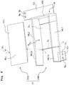
- FIG. 1 is an exploded perspective view of a load detector according to a first embodiment of the present disclosure.
- FIG. 2 is a perspective view of the load detector according to the first embodiment of the present disclosure.
- FIG. 3 is an exploded perspective view of a platform included in the load detector according to the first embodiment of the present disclosure.
- FIG. 4A depicts placement of a caster on the platform, in particular, a situation before the caster is placed on the platform
- FIG. 4B depicts placement of the caster on the platform, in particular, a situation after the caster is placed on the platform.
- FIG. 5 is an illustrative view illustrating the relation between positions at which the platform is fixed to load cells and a proper placement position of an object to be detected (detection target) on the platform.
- FIG. 6 is an illustrative view illustrating a placement position of a detection target on a mounting plate in a load detector using a single beam-type load cell.
- FIG. 7 is an illustrative view illustrating distances, in a longitudinal direction and a width direction, between a position of the detection target on the platform and positions at which the platform is fixed to the load cells.
- FIG. 8 is an exploded perspective view of a platform according to a first modified example of the present disclosure.
- FIG. 9A depicts placement of the caster on the platform according to the first modified example of the present disclosure, in particular, a situation before the caster is placed on the platform
- FIG. 9B depicts placement of the caster on the platform according to the first modified example of the present disclosure, in particular, a situation after the caster is placed on the platform.
- FIG. 10 is an exploded perspective view of a platform according to a second embodiment of the present disclosure.
- FIG. 11A depicts placement of the caster on the platform according to the second embodiment of the present disclosure, in particular, a situation before the caster is placed on the platform
- FIG. 11B depicts placement of the caster on the platform according to the second embodiment of the present disclosure, in particular, a situation after the caster is placed on the platform.
- FIG. 12 is an exploded perspective view of a platform according to a second modified example of the present disclosure.
- FIG. 13A depicts placement of the caster on the platform according to the second modified example of the present disclosure, in particular, a situation before the caster is placed on the platform
- FIG. 13B depicts placement of the caster on the platform according to the second modified example of the present disclosure, in particular, a situation after the caster is placed on the platform.
- FIG. 14 is a perspective view of a platform according to a third modified example of the present disclosure.
- FIG. 15A depicts placement of the caster on the platform according to the third modified example of the present disclosure, in particular, a situation before the caster is placed on the platform
- FIG. 15B depicts placement of the caster on the platform according to the third modified example of the present disclosure, in particular, a situation in which the caster is positioned on a slope.
- FIG. 16 is a modified aspect of a first connection part and a second connection part of the platforms according to the embodiments and the modified examples, wherein only a wall of a main body, of which shape is common in the embodiments and the modified examples, is depicted and the illustration of a plate is omitted.
- FIG. 17 is a schematic view depicting a configuration of a load detection system according to a third embodiment of the present disclosure.
- the load detector 100 is a load detector that is disposed under a leg BL ( FIGS. 4A and 4B ) of a bed to detect a load of a human subject (subject) on the bed.
- the load detector 100 mainly includes a first base 11 , a second base 12 , a first load cell 21 of a beam type that is connected to the first base 11 , a second load cell 22 of a beam type that is connected to the second base 12 , and a platform (mounting part) 30 that is supported by the first and second load cells 21 , 22 to be positioned therebetween.
- a direction in which beams of the beam-type first and second load cells 21 , 22 extend is defined as a longitudinal direction.
- a surface on which the load detector 100 is placed is referred to as a floor.
- the first base 11 is a member disposed on the floor to support the first load cell 21 in a cantilever manner.
- the first base 11 includes a flat plate 11 a , of which planar shape is a rectangle almost identical to the planer shape of the first load cell 21 , and a support base part 11 b that extends upward from an end of the flat plate 11 a .
- Atop surface 11 bt of the support base part 11 b is positioned above a top surface 11 at of the flat plate 11 a.
- the top surface 11 bt of the support base part 11 b includes two screw holes Th.
- the first load cell 21 is fixed to the support base part 11 b via screws T and the screw holes Th.
- the second base 12 which has the same shape as the first base 11 , includes a flat plate 12 a and a support base part 12 b .
- the second base 12 is disposed to face the first base 11 (to be parallel to the first base 11 in the first embodiment) with a predefined distance intervening therebetween, and the support base part 11 b of the first base 11 is positioned on a side opposite to the side on which the support base part 12 b is positioned.
- the support base part 11 b is connected to the flat plate 11 a of the first base 11 on a side opposite to the side on which the support base part 12 b is connected to the flat plate 12 a of the second base 12 , in the longitudinal direction.
- the second load cell 22 is fixed to the support base part 12 b via screws T and screw holes Th formed in the top surface 12 bt of the support base part 12 b.
- the first load cell 21 which is a beam-type load cell, includes a flexure element (strain body) 21 s in a rectangular column shape that has a through hole h, and a strain gage 21 g attached on the flexure element 21 s .
- the first load cell 21 detects the strain or distortion generated in the flexure element 21 s as the change in a resistance value of the strain gage 21 g . Accordingly, the load applied to the first load cell 21 is detected.
- the flexure element 21 s is a long square pillar made of metal such as aluminum or iron.
- the through hole h which passes through the flexure element 21 s in the width direction, is formed in the center portion in the longitudinal direction of the flexure element 21 s .
- the through hole h includes two circular holes hc and a rectangular hole hr. Each of the circular holes hc has a circular cross-sectional shape, and the rectangular hole hr, which has a substantially rectangular cross-sectional shape, connects the two circular holes hc to each other in the longitudinal direction.
- Parts, of the flexure element 21 s , positioned on the upper and lower sides of the through hole h are thin parts 21 th that are thinner in the up-down direction due to existence of the through hole h.
- Two screw holes Th passing through the flexure element 21 s in the up-down direction are formed in the vicinity of a first end 21 ss of the flexure element 21 s .
- the first end 21 ss of the flexure element 21 s is fixed to the support base part 11 b of the first base 11 via screws T and the screw holes Th. This allows the flexure element 21 s to be supported by the first base 11 (support base part 11 b ) in a cantilever manner with the first end 21 ss being a fixed end, the second end 21 sf being a free end.
- two screw holes Th passing through the flexure element 21 s in the up-down direction are formed in the vicinity of the second end 21 sf of the flexure element 21 s .
- the platform 30 is fixed to a lower surface 21 sd of the flexure element 21 s in the vicinity of the second end 21 sf via the screws T and the screw holes Th.
- the flexure element 21 s (first load cell 21 ) supports the platform 30 in the vicinity of the second end 21 sf as the free end so that the platform 30 is movable in the up-down direction.
- Two strain gages 21 g are attached to the thin parts 21 th of the flexure element 21 s . Specifically, one of the two strain gages 21 g is attached to an upper surface 21 st of the flexure element 21 s and the other of the two strain gages 21 g is attached to the lower surface 21 sd of the flexure element 21 s , at the substantially center portion in the longitudinal direction of the flexure element 21 s .
- the strain gages 21 g are connected to an external controller via unillustrated lead wires.
- the second load cell 22 which has the same structure as the first load cell 21 , includes a flexure element (strain body) 22 s in a rectangular column-shape and two strain gages 22 g .
- the flexure element 22 s includes a through hole h passing through the center portion of the flexure element 22 s in the width direction.
- Each of the strain gages 22 g is attached to the corresponding one of thin parts 22 th of the flexure element 22 s .
- the second load cell 22 is disposed to face the first load cell 21 (to be parallel to the first load cell 21 in first embodiment) with a predefined distance intervening therebetween.
- Two screw holes Th passing through the flexure element 22 s in the up-down direction are formed in the vicinity of a first end 22 ss of the flexure element 22 s .
- the first end 22 ss of the flexure element 22 s is fixed to the support base part 12 b of the second base 12 via screws T and the screw holes Th. This allows the flexure element 22 s to be supported by the second base 12 (support base part 12 b ) in a cantilever manner with the first end 22 ss being a fixed end, a second end 22 sf being a free end.
- two screw holes Th passing through the flexure element 22 s in the up-down direction are formed in the vicinity of the second end 22 sf of the flexure element 22 s .
- the platform 30 is fixed to a lower surface 22 sd of the flexure element 22 s in the vicinity of the second end 22 sf via screws T and the screw holes Th.
- the flexure element 22 s (second load cell 22 ) supports the platform 30 in the vicinity of the second end 22 sf as the free end so that the platform 30 is movable in the up-down direction.
- the first end (fixed end) 22 ss of the flexure element 22 s is in the same position, in the longitudinal direction, as the second end (free end) 21 sf of the flexure element 21 s
- the second end (free end) 22 sf of the flexure element 22 s is in the same position, in the longitudinal direction, as the first end (fixed end) 21 ss of the flexure element 21 s .
- the flexure element 21 s and the flexure element 22 s extend in the same direction while facing each other, and the fixed end and the free end of the flexure element 21 s are positioned reversely to the fixed end and the free end of the flexure element 22 s in the longitudinal direction.
- the support base part 11 b supporting the flexure element 21 s is in substantially the same position as the second end (free end) 22 sf of the flexure element 22 s in the longitudinal direction
- the support base part 12 b supporting the flexure element 22 s is in substantially the same position as the second end (free end) 21 sf of the flexure element 21 s in the longitudinal direction.
- the platform 30 is a platform on which an object to be detected (detection object, detection target) is placed when a load of the detection target is to be detected by the load detector 100 .
- the platform 30 includes a main body 30 M and a guide 30 G that is attached to the main body 30 M so that the guide 30 G moves swingably (moves like a seesaw, or moves pivotally).
- the main body 30 M includes a rectangular plate P 30 on which the detection target is placed, a wall W surrounding the plate P 30 on three sides thereof, and a first connection part C 1 and a second connection part C 2 that are provided in the wall W.
- the first and second connection parts C 1 and C 2 are provided in the wall W.
- a side, on which the detection target described below is placed, relative to the plate P 30 is defined as the upper side of the main body 30 M and the plate P 30 (above the main body 30 M and the plate P 30 ), and its opposite side is defined as the lower side of the main body 30 M and the plate P 30 (below the main body 30 M and the plate P 30 ).
- a recess R 30 which has substantially a C-shape or U-shape in plan view, is provided in the upper surface of the plate P 30 .
- the recess R 30 is formed so that an opening portion of the C-shape (U-shape) is positioned on one side in the long-side direction of the plate P 30 (on a side having no wall W).
- One of short sides of the plate P 30 not having the wall W is provided with a shaft support part S, which has a rectangular parallelepiped shape and disposed at the center portion of the short side.
- the shaft support part S is provided with bosses B protruding toward both sides in the short-side direction of the plate P 30 .
- the wall W which is perpendicular (orthogonal) to the plate P 30 , includes a first long wall WL 1 extending along one of the long sides of the plate P 30 , a second long wall WL 2 extending along the other of the long sides of the plate P 30 , and a short wall WS extending along one of the short sides of the plate P 30 and connecting the first long wall WL 1 and the second long wall WL 2 .
- first protrusion WL 1 p a protruding portion of the first long wall WL 1
- second protrusion WL 2 p a protruding portion of the second long wall WL 2
- the inner surfaces, of the first protrusion WL 1 p and the second protrusion WL 2 p , facing each other are tapered so that a distance between the inner surfaces are longer as the inner surfaces are further separated from the plate P 30 in the long-side direction of the plate P 30 .
- the first connection part C 1 which has a plate-like shape and is parallel to the plate P 30 , is provided in the outer surface of the first protrusion WL 1 p .
- the first connection part C 1 which has a substantially square shape in plan view, has two screw holes Th at substantially the center portion.
- the first connection part C 1 is fixed to the lower surface 21 sd of the flexure element 21 s of the first load cell 21 in the vicinity of the second end (free end) 21 sf of the flexure element 21 s via the screws T and the screw holes Th ( FIGS. 1 and 2 ).
- the outer surface, of the short wall WS, facing a side opposite to the side on which the plate P 30 is positioned is provided with the second connection part C 2 having a plate-like shape and being parallel to the plate P 30 .
- the second connection part C 2 has a rectangular shape of which longitudinal direction is the extending direction of the short wall WS. An end in the longitudinal direction of the second connection part C 2 extends beyond the second long wall WL 2 . The portion extending beyond the second long wall WL 2 has two screw holes Th.
- the second connection part C 2 is fixed to the lower surface 22 sd of the flexure element 22 s of the second load cell 22 in the vicinity of the second end (free end) 22 sf of the flexure element 22 s via the screws T and the screw holes Th ( FIGS. 1 and 2 ). As depicted in FIGS. 2 and 3 , the screw holes Th of the first connection part C 1 and the screw holes Th of the second connection part C 2 are arranged with the plate P 30 intervening therebetween in the diagonal direction.
- the guide 30 G which has a plate-like shape, includes a slope SL 30 and a lever LV 30 connected integrally with the slope SL 30 .
- the slope SL 30 has substantially a rectangular shape in plan view.
- the upper surface of the slope SL 30 defines an inclined surface (slope) for moving a rolling body (e.g., a caster CT) from the floor onto the platform 30 .
- a notch n which has substantially a rectangular shape in plan view, is defined at the center portion of a long side (a first end) to which the lever LV 30 is connected. Surfaces facing each other and defining short sides of the notch n respectively include recessed holes c.
- the slope SL 30 is thicker than the lever LV 30 (see FIGS. 3, 4A, and 4B ).
- the slope SL 30 is tapered toward a front end SLT (a second end).
- the lever LV 30 is an extending part that extends from the first end of the slope SL 30 toward an opposite side of the front end SLT.
- the lever LV 30 includes a first arm AM 1 and a second arm AM 2 which are connected to ends of the long sides of the rectangular slope SL 30 , and a rectangular part (contact part) RC that is disposed on an opposite side of the slope SL 30 and connected to the first arm AM 1 and the second arm AM 2 .
- the lever LV 30 has substantially a C-shape (U-shape) in plan view.
- the guide 30 G is attached to the main body 30 M so that the guide 30 G can move swingably. Specifically, fitting the bosses B of the shaft support part S of the plate P 30 into the recessed holes c of the notch n of the slope SL 30 allows the guide 30 G to be connected to the main body 30 M so that the guide 30 G seesaws (swings) around a swing shaft X 30 connecting the bosses B and the recessed holes c.
- the guide 30 G is configured so that weight of the front side of the recessed holes c (a side close to the front end SLT of the slope SL 30 ) is greater than weight of the rear side of the recessed holes c (a side close to the lever LV 30 ) by differentiating the thickness and structure of the slope SL 30 from those of the lever LV 30 , in the extending direction of the guide 30 G.
- the guide 30 G moves like a seesaw, with the swing shaft X 30 as the center, in a direction in which the front end SLT moves down, when no load is applied to the lever LV 30 . This makes the front end SLT contact with the floor.
- the slope SL 30 may include a mechanism that urges (biases) the front end SLT with a spring, a magnet, or the like toward the floor.
- the shape of the recess R 30 of the plate P 30 of the main body 30 M in plan view is substantially the same as the shape of the lever LV 30 of the guide 30 G in plan view.
- the lever LV 30 is disposed in the recess R 30 ( FIG. 4B ).
- the upper surface of the lever LV 30 may be flush with the upper surface of the plate P 30 .
- the caster CT When the load detection using the load detector 100 is performed, at first, the caster CT is placed on the plate P 30 of the main body 30 M of the platform 30 . In a state where the caster CT is not placed on the plate P 30 ( FIG. 4A ), the front end SLT of the slope SL 30 is in a first position where the front end SLT is brought into contact with a floor F due to the weight of the slope SL 30 . In that situation, since there is no height difference between the floor F and the slope SL 30 , the caster CT easily moves obliquely upward along the upper surface (inclined surface) of the slope SL 30 . Then, the caster CT reaches the front end of the plate P 30 of the main body 30 M, namely, a position on the swing shaft X 30 . So far, the guide 30 G has no posture change.
- the caster CT that has reached the front end of the plate P 30 (i.e., the position on the swing shaft X 30 ) passes the position on the swing shaft X 30 and moves toward the short wall WS, the caster CT runs on a rectangular part RC of the lever LV 30 of the guide 30 G which pushes the rectangular part RC downward.
- the caster CT stops at the timing at which the caster CT comes into contact with the short wall WS, and the placement ends.
- the front end SLT of the slope SL 30 swings to be in a second position where the front end SLT is separated from the floor. In the second position, the entirety of the slope SL 30 including the front end SLT is separated from the floor. Further, a flat surface is defined by the upper surface of the plate P 30 and the upper surface of the lever LV 30 and the caster CT is positioned on the flat surface. This eliminates, for example, a measurement error which may otherwise be caused by movement of the caster CT due to the height difference between the upper surface of the plate P 30 and the upper surface of the rectangular part RC. In order to prevent rotational movement of the caster CT, the caster CT may be locked after being placed on the platform 30 .
- the platform 30 of the first embodiment is configured so that the center portion in plan view of the caster CT, which is brought into contact with the wall W and is placed on the plate P 30 , is positioned, in plan view, on a line L or in the vicinity thereof.
- the line L connects a connection position between the first connection part C 1 and the first load cell 21 and a connection position between the second connection part C 2 and the second load cell 22 .
- the line L is similar to the diagonal line of the plate P 30 , they are not identical.
- the line L may be identical to the diagonal line of the plate P 30 .
- Casters attached to other legs of the bed are similarly placed on pieces of the load detector 100 .
- the load of the human subject on the bed is transmitted to the flexure element 21 s of the first load cell 21 and the flexure element 22 s of the second load cell 22 that support the platform 30 , via the bed leg BL, the caster CT, and the platform 30 .
- the load transmitted generates the strain in the flexure element 21 s and the flexure element 22 s , and the strain gages 21 g , 22 g each detect the strain as the change in a resistance value.
- the change in the resistance value is outputted to the controller (not depicted in the drawing) that is provided outside the load detector 100 , provided in the first base 11 , or provided in the second base 12 , via lead wires (not depicted in the drawing). Performing Arithmetic processing by the controller determines the load of the human subject.
- the main body 30 M of the platform 30 is supported in the vicinity of the second end 21 sf of the flexure element 21 s of the first load cell 21 via the first connection part C 1 , and is supported in the vicinity of the second end 22 sf of the flexure element 22 s of the second load cell 22 via the second connection part C 2 , to be movable in the up-down direction.
- the line L connecting the fixing center A 1 and the fixing center A 2 in the shortest distance is a part, of the main body 30 M of the platform 30 , which is least likely to bend.
- the main body 30 M of the platform 30 of the load detector 100 is configured so that the caster CT brought into contact with the short wall WS is positioned on the line L or in the vicinity thereof.
- the caster CT brought into contact with the short wall WS is positioned on the line L or in the vicinity thereof.
- the load detector 100 of the present disclosure can detect a load more stably and accurately. The reason thereof is explained while referring to a single-load-cell-type load detector 900 depicted in FIG. 6 . As depicted in FIG.
- the single-load-cell-type load detector 900 in which a mounting plate PT is connected to an end of a beam-type load cell LC, has a relatively small position deviation error, in a case that a placement position pn of a detection target is in the vicinity of a connection position A 0 between the beam-type load cell LC and the mounting plate PT.
- the position deviation error increases as the distance between the placement position pn and the connection position A 0 is longer. The reason thereof is as follows.
- the bending moment acts on a flexure element of the beam-type load cell LC around an axis extending in the width direction of the beam-type load cell LC to cause the strain in the flexure element.
- This strain causes the position deviation error in a strain gage of the beam-type load cell LC.
- the torsional or twisting moment acts on the flexure element of the beam-type load cell LC around an axis extending in the longitudinal direction of the beam-type load cell LC to cause the strain in the flexure element. This strain causes the position deviation error in the strain gage of the beam-type load cell LC.
- a distance, in the longitudinal direction, between the fixing center A 1 and a placement position PN of the detection target placed on the plate P 30 of the main body 30 M of the platform 30 is defined as a distance x P1 and that a distance, in the longitudinal direction, between the fixing center A 2 and the placement position PN is defined as a distance x P2
- the total of the distances x P1 , x P2 is constant over almost the whole area of the plate P 30 of the main body 30 M.
- the total of the position deviation error caused in the first load cell 21 by the bending moment and the position deviation error caused in the second load cell 22 by the bending moment is approximately constant (a value having a certain ratio to the weight of the detection target) at all times. Therefore, the effect of the position deviation error caused by the bending moment is virtually removed, for example, by allowing the controller (not depicted in the drawings) to sum up detection values of the first load cell 21 and the second load cell 22 and to subtract a certain value (the value having the certain ratio to the weight of the detection target) as the position deviation error therefrom. Accordingly, the load of the detection target can be detected stably.
- a distance, in the width direction, between the fixing center A 1 and the placement position PN of the detection target placed on the plate P 30 of the main body 30 M is defined as a distance y P1 and that a distance, in the width direction, between the fixing center A 2 and the placement position PN is defined as a distance y P2
- the total of the distances y P1 , y P2 is constant over almost the whole area of the plate P 30 of the main body 30 M.
- the total of the position deviation error caused in the first load cell 21 by the torsional moment and the position deviation error caused in the second load cell 22 by the torsional moment is approximately constant (a value having a certain ratio to the weight of the detection target) at all times. Therefore, the effect of the position deviation error caused by the torsional moment is virtually removed, for example, by allowing the controller (not depicted in the drawings) to sum up detection values of the first load cell 21 and the second load cell 22 and to subtract a certain value (the value having the certain ratio to the weight of the detection target) as the position deviation error therefrom. Accordingly, the load of the detection target can be detected stably.
- the platform 30 of the load detector 100 of the first embodiment includes the main body 30 M and the guide 30 G that is movable like a seesaw relative to the main body 30 M.
- the rolling body e.g., the caster CT
- the slope SL 30 having the front end SLT brought into contact with the floor F can thus be placed on the main body 30 M easily.
- the rolling body e.g., the caster CT
- pushing the lever LV 30 of the guide 30 G toward the main body 30 M causes the guide 30 G to move like a seesaw (swing), which separates the front end SLT of the slope SL 30 from the floor F.
- the state where the slope SL 30 is separated from the floor F is maintained as long as the rolling body is present on the main body 30 M.
- the load detection that is performed by placing the detection target on the main body 30 M does not have a measurement error which may otherwise be caused by the contact between the guide 30 G and the floor F.
- the platform 30 of the load detector 100 of the first embodiment most of the load from the rolling body (e.g., the caster CT) is applied to the plate P 30 , and only a part of the load from the rolling body (e.g., the caster CT) is applied to the guide 30 G via the rectangular part RC of the lever LV 30 . That configuration reduces the load applied to the swing shaft X 30 over time, preventing components or parts, such as the bosses B and the recessed holes C, from being damaged. It is desired that the depth of the recess R 30 (the height of the upper surface of the plate P 30 relative to the bottom surface of the recess R 30 ) is greater than the thickness of the lever LV 30 .
- This configuration has a gap (backlash) between the lower surface of the lever LV 30 and the bottom surface of the recess R 30 , and the load from the rolling body (e.g., the caster CT) is applied only to the plate P 30 , making it possible to further reduce the load on the swing shaft X 30 .
- the load from the rolling body e.g., the caster CT
- the platform 30 includes the first connection part C 1 and the second connection part C 2 on both sides in the diagonal direction of the plate P 30 of the main body 30 M, and the platform 30 is supported by the first load cell 21 and the second load cell 22 via the first connection part C 1 and the second connection part C 2 to be movable in the up-down direction.
- disposing the detection target on the line L that is similar to or the same as the diagonal line of the plate P 30 ) connecting the connection position between the first connection part C 1 and the first load cell 21 and the connection position between the second connection part C 2 and the second load cell 22 results in a successful load detection of the detection target without suffering the effect of bending of the plate P 30 .
- the total value of position deviation errors that are caused in the first and second load cells 21 , 22 by the bending moment and the total value of position deviation errors that are caused in the first and second load cells 21 , 22 by the torsional moment are approximately constant at all times. Therefore, the effect of each position deviation error is virtually removed by summing up detection values of the first load cell 21 and the second load cell 22 and subtracting the position deviation error, which is an approximately constant value, therefrom. Accordingly, the load detection can be performed stably and precisely.
- the first arm AM 1 and the second arm AM 2 of the lever LV 30 of the guide 30 G of the platform 30 may be connected to the slope SL 30 in the vicinity of the center portion in the longitudinal direction of the slope SL 30 . Any one of the first arm AM 1 and the second arm AM 2 may be omitted.
- the number of arms and the arrangement thereof may be changed so that the rolling body placed on the platform 30 does not apply an unnecessary load to the guide 30 G via the arm(s).
- a platform 31 of the first modified example is the same as the platform 30 of the first embodiment, except that a lever LV 31 of a guide 31 G is a rectangular flat plate having no opening, that a recess R 31 having a rectangular shape in plan view is provided in a plate P 31 of a main body 31 M instead of the recess R 30 having substantially a C-shape in plan view, and that the guide 31 G is connected to the main body 31 M by fitting the bosses B provided in the slope SL 31 into the recess holes c provided in the wall W of the main body 31 M.
- the rolling body e.g., the caster CT
- the rolling body can be introduced on the platform 31 of the first modified example, similarly to the introduction of the rolling body on the platform 30 provided in the load detector 100 of the first embodiment.
- the caster CT that passed a position on a swing shaft X 31 runs on the lever LV 31 of the guide 31 G, pushing the lever LV 31 downward.
- the lever LV 31 of the guide 31 G is fitted into the recess R 31 of the plate P 31 of the main body 31 M, and thus the entirety of the slope SL 31 including the front end SLT is separated from the floor.
- the caster CT stops at the timing at which the caster CT comes into contact with the short wall WS, and the placement ends.
- the caster CT that passes the position on the swing shaft X 31 and runs toward the short wall WS moves rotatably only on the upper surface of the lever LV 31 having a flat plate shape, and then placed on the upper surface of the lever LV 31 .
- the lever LV 31 is flat, has no opening, and has no height difference between the lever LV 31 and another part.
- the caster CT is surely placed on the flat surface irrespective of the position on the platform where the caster CT stops. This prevents a measurement error which may otherwise be caused by the height difference, between the lever LV 31 and another part, which would affect the caster CT.
- a platform 32 of the second embodiment is the same as the platform 31 of the first modified example, except that a groove G 1 having an arc-like shape and extending in the short-side direction of a plate P 32 is provided in a recess R 32 , which has a rectangular shape in plan view, of the plate P 32 of a main body 32 M, and that a groove (movement regulation part) G 2 which has an arc-like shape and of which shape and arrangement correspond to those of the groove G 1 , is provided in a lever LV 32 of a guide 32 G
- the rolling body e.g., the caster CT
- the rolling body can be introduced on the platform 32 of the second embodiment, similarly to the introduction of the rolling body on the platform 31 of the first modified example.
- the caster CT that passed a position on a swing shaft X 32 runs on the lever LV 32 of the guide 32 Q pushing the lever LV 32 downward.
- the entirety of the slope SL 32 including the front end SLT is separated from the floor.
- the caster CT that passes the position on the swing shaft X 32 and moves toward the short wall WS runs on the lever LV 32 , and stops by being fitted into the groove G 2 ( FIG. 11B ).
- the groove G 2 functions to position the caster CT at an appropriate detection position on the platform 32 .
- the groove G 2 also functions to keep the caster CT on the platform 32 even when force acts on the caster CT due to an earthquake, an unexpected contact, or an unexpected collision.
- the shapes of the grooves G 1 and G 2 are not limited to those depicted in FIGS. 11A and 11B , and each of the grooves G 1 and G 2 may have any shape.
- a platform 33 of the second modified example is mainly different from the platform 30 of the load detector 100 according to the first embodiment in that a lever LV 33 of a guide 33 G is a member that is rectangular in plan view and is disposed below a main body 33 M, and that a plate P 33 of the main body 33 M is a flat plate having an opening OP.
- the guide 33 G is attached to the main body 33 M so that the guide 33 G moves like a seesaw around a swing shaft X 33 by fitting the bosses B protruding from the shaft support part S of the lever LV 33 into the recessed holes c of the notch n of the plate P 33 of the main body 33 M. In that situation, the lever LV 33 is disposed below the opening OP.
- the rolling body e.g., the caster CT
- the rolling body can be introduced on the platform 33 of the second modified example, similarly to the introduction of the rolling body on the platform 30 of the load detector 100 of the first embodiment.
- the caster CT that passed a position on the swing shaft X 33 runs on the plate P 33 of the main body 33 M toward the short wall WS.
- the caster CT stops by being fitted into the opening OP of the plate P 33 , which pushes the lever LV 33 of the guide 33 G downward. This causes the guide 33 G to move like a seesaw around the swing shaft X 33 , and the entirety of a slope SL 33 including the front end SLT is separated from the floor F.
- the opening OP of the plate P 33 of the second modified example positions the caster CT at an appropriate detection position and prevents the caster CT from falling from the platform 33 due to unexpected external force.
- fitting the rolling body (e.g., the caster CT) into the opening OP causes the guide 33 G to swing, which moves the slope SL 33 upward.
- a user can check whether the rolling body (e.g., the caster CT) is fitted into the opening OP and positioned at the appropriate detection position only by visually checking, at the time of placement for example, whether the front end SLT of the slope SL 33 moves upward.
- the entire load of the caster CT is applied to the main body 33 M in the state where the caster CT is fitted into the opening OP and positioned at the appropriate detection position. That configuration reduces the load applied to the swing shaft X 33 over time, preventing components or parts, such as the bosses B and the recessed holes C, from being damaged.
- a platform 34 of the third modified example is the same as the platform 30 of the load detector 100 of the first embodiment, except that a guide 34 G has no lever, no recess is formed on the upper surface of a plate P 34 of a main body 34 M, and an urging (biasing) member that urges (biases) the front end SLT of the guide 34 G upward is provided.
- the urging member is torsion spring(s) (not depicted) that is/are disposed to surround boss(es) (not depicted) protruding from the shaft support part S.
- the front end SLT of the guide 34 G is in the second position where the front end SLT is separated from the floor F, even when the rolling body (e.g., the caster CT) is not placed on the platform 34 .
- the front end SLT is in the first position where the front end SLT is brought into contact with the floor F, only when the rolling body is positioned on the guide 34 G.
- the platform 34 is different from the platforms 30 , 31 , 32 , and 33 according to the above embodiments and modified examples in which the front end SLT of the slope is in the first position where the front end SLT is brought into contact with the floor F when the rolling body is not placed on each of the platforms 30 , 31 , 32 , and 33 .
- the caster CT When the caster CT is introduced on the platform 34 , the caster CT may be positioned on the floor F in the vicinity of the platform 34 ( FIG. 15A ). In that case, the guide 34 G of the platform 34 is urged by the torsion spring(s), so that the front end SLT of the guide 34 G is in the second position where the front end SLT is separated from the floor F.
- the caster CT runs on the front end SLT of the guide 34 G and pushes the guide 34 G downward.
- the caster CT runs on a slope defined on the upper surface of the guide 34 G rotatably moves obliquely upward on the slope, and reaches the main body 34 M.
- the rolling body that passes a position on the swing shaft X 34 and moves toward the short wall WS rotatably moves only on the upper surface of the flat plate P 34 of the main body 34 M and then is placed on the upper surface of the plate P 34 .
- the platform 34 of the third modified example may not have a structure that urges the front end SLT of the guide 34 G upward, such as the torsion spring.
- the guide 34 G is attached to the main body 34 M in accordance with such an aspect that the upper surface of the guide 34 G can swingably move to a position where the upper surface of the guide 34 G comes into contact with the upper surface of the plate P 34 .
- a user manually operates the guide 34 G so that the guide 34 G swings. After the user places the rolling body (e.g., the caster CT) on the platform 34 , the guide 34 G is kept on the plate P 34 in a state where the upper surface of the guide 34 G is brought into contact with the upper surface of the plate P 34 .
- the first connection part C 1 and the second connection part C 2 included in the main bodies 30 M, 31 M, 32 M, 33 M, and 34 M of the platforms 30 , 31 , 32 , 33 , and 34 may be configured as depicted in FIG. 16 .
- the first connection part C 1 has a vertical part C 1 v extending upward and parallel to the first long wall WL 1 , and a horizonal part C 1 h extending from the upper end of the vertical part C 1 v in the horizonal direction, which is perpendicular (orthogonal) to the vertical part C 1 v .
- the second connection part C 2 has a first horizonal part C 2 h 1 having a rectangular shape in plan view and extending from the short wall WS in the horizontal direction, a vertical part C 2 v extending upward from a short side on the second long wall WL 2 side of the first horizontal part C 2 h 1 , and a second horizonal part C 2 h 2 extending from the upper end of the vertical part C 2 v in the horizonal direction, which is perpendicular to the vertical part C 2 v .
- the first connection part C 1 is connected to the upper surface 21 st of the flexure element 21 s in the vicinity of the second end 21 sf of the flexure element 21 s of the first load cell 21 .
- the second connection part C 2 is connected to the upper surface 22 st of the flexure element 22 s in the vicinity of the second end 22 sf of the flexure element 22 s of the second load cell 22 .
- the first connection part C 1 may be a surface connected to the front end of the protrusion WL 1 p of the first long wall WL 1 and parallel to the short wall WS. In that case, the platform is attached to the first load cell 21 by fixing the surface to an end surface in the longitudinal direction of the flexure element 21 s of the first load cell 21 .
- the second connection part C 2 is attached to the first load cell 21 by fixing the surface to an end surface in the longitudinal direction of the flexure element 21 s of the first load cell 21 .
- each of the platforms 30 , 31 , 32 , 33 , and 34 of the above embodiments and modified examples it is not indispensable to arrange the first connection part C 1 and the second connection part C 2 on the diagonal line of each of the plates P 30 , P 31 , P 32 , P 33 , and P 34 provided that the first connection part C 1 and the second connection part C 2 are arranged with each of the plates P 30 , P 31 , P 32 , P 33 , and P 34 intervening therebetween in the diagonal direction.
- the first connection part C 1 may be attached to the flexure element 21 s of the first load cell 21 on the second end 21 sf side (free end side) relative to the center portion in the longitudinal direction.
- the first connection part C 1 may be attached to the flexure element 21 s of the first load cell 21 at any position on the free end side of the thin part 21 th .
- the second connection part C 2 may be attached to the flexure element 22 s of the second load cell 22 on the second end 22 sf side (free end side) relative to the center portion in the longitudinal direction.
- Each of the platforms 30 , 31 , 32 , 33 , and 34 of the above embodiments and modified examples can be used as a platform of the single-load-cell-type load detector 900 such as depicted in FIG. 6 .
- the first connection part C 1 and the second connection part C 2 are not required to be provided in the main bodies 30 M, 31 M, 32 M, 33 M, and 34 M of the platforms 30 , 31 , 32 , 33 , and 34 .
- the front end of the load cell LC is fixed and connected to the short wall WS.
- each of the platforms 30 , 31 , 32 , 33 , and 34 of the above embodiments and modified examples can be used as a measuring pan of a load scale having three load cell sensors, such as described in Patent Literature 1.
- Each of the platforms 30 , 31 , 32 , 33 , and 34 of the above embodiments and modified examples may not have the wall W.
- each of the platforms 30 , 31 , 32 , 33 , and 34 of the above embodiments and modified examples the above-described method of connecting each of the guides 30 G 31 G 32 G 33 G and 34 G to the corresponding one of the main bodies 30 M, 31 M, 32 M, 33 M, and 34 M in such a manner that the guide can move like a seesaw or can swing relative to the main body is an example, and any other method may be used.
- the positional relation between the bosses B and the recessed parts c used in the platform 30 of the first embodiment may be opposite thereto.
- a shaft may pass through the guide instead of providing the bosses B.
- the slopes SL 30 , SL 31 , SL 32 , and SL 33 of the guides 30 G 31 G 32 G and 33 G move to the positions in contact with the floor F, due to their own weight.
- the present disclosure is not limited thereto.
- An urging member e.g., a torsion spring, a plate spring, and a magnet
- a torsion spring e.g., a torsion spring, a plate spring, and a magnet
- An urging member that urges the front end SLT of each of the slopes SL 30 , SL 31 , SL 32 , and SL 33 downward may be provided between each of the main bodies 30 M, 31 M, 32 M, and 33 M and each of the guides 30 G 31 G 32 G and 33 G of each of the platforms 30 , 31 , 32 , and 33 .
- a weight may be attached to each of the slopes SL 30 , SL 31 , SL 32 , and SL 33 of the corresponding one of guides 30 G 31 G 32 G and 33 G thus moving the front end SLT of each of the slopes SL 30 , SL 31 , SL 32 , and SL 33 downward.
- the first base 11 and the second base 12 are parts or components separated from each other.
- the present disclosure is not limited thereto.
- the first base 11 and the second base 12 may be formed integrally.
- a flat plate extending below each of the platforms 30 , 31 , 32 , 33 , and 34 may connect the flat plate 11 a and the flat plate 12 a.
- the first load cell 21 and the second load cell 22 face each other in parallel.
- the first load cell 21 and the second load cell 22 may face each other while having an angle smaller than about 5°.
- strain gages 21 g are attached to the flexure element 21 s of the first load cell 21 and two strain gages 22 g are attached to the flexure element 22 s of the second load cell 22 .
- the present disclosure is not limited thereto, and three or more of strain gages 21 g , 22 g may be attached to the flexure elements 21 s , 22 s , respectively.
- the load detection system 500 mainly includes four load detectors 100 and a controller CONT.
- the four load detectors 100 are connected to the controller CONT by wiring.
- the controller CONT connected to the four load detectors 100 executes load calculation processing in which the output from the first load cell 21 and the output from the second load cell 22 of each load detector 100 are summed and a certain value corresponding to a position deviation error is subtracted, and load summing-up processing in which the loads detected by the load detectors 100 are summed.
- the controller CONT may execute any other processing.
- the load detection system of the third embodiment uses the load detector 100 including the platform 30 according to the first embodiment, thereby obtaining the same effects as those of the platform 30 according to the first embodiment.
- the bed BD can be placed on the four platforms 30 only by moving the bed BD in one direction so that the four casters CT of the bed BD rotate to run on the slope SL 30 of the guide 30 M. This achieves the placement of the bed BD on the load detectors 100 with less trouble and less manpower.
- the number of load detectors 100 is not limited to four. Three or less or five or more of load detectors 100 may be used in the load detection system. Further, the load detector 100 may include, instead of the platform 30 , each of the platform 31 , 32 , 33 , and 34 according to the second embodiment and the modified examples.
- the output from each load detector 100 may be transmitted to the controller CONT wirelessly rather than wiring.
- the controller CONT may be connected to an indicator indicating the load determined by the controller CONT and an alarm giving a predefined alarm based on the determined load.
- the present invention is not limited to the above embodiments and its modified examples provided that the characteristics of the present invention can be obtained.
- the present invention includes any other embodiments which can be conceived in the range of the technical ideas of the present invention.
- the load detector according to the above embodiments may further include a lever connected to the first end of the slope and extending from the first end of the slope toward an opposite side of the second end of the slope.
- the lever may include a contact part configured to move by being pushed by the subject on the main body and an arm connecting the contact part and the slope.
- a recess configured to accommodate the lever may be provided in an upper surface of the main body.
- the lever may include a movement regulation part configured to regulate movement of the subject placed on the main body.
- the main body may include an opening.
- the load detector according to the above embodiments may further include a lever connected to the first end of the slope and disposed below the main body to cover the opening.
- the load detector according to the above embodiments may further include an urging member configured to urge the second end of the slope toward the second position.
- the main body may include a plate configured to keep or retain the subject during load detection and a wall provided on the plate.
- the beam-type load cell may include a first beam-type load cell which is supported on a first support base in a cantilever manner to have a free end and a second beam-type load cell which is disposed to face the first beam-type load cell and which is supported on a second support base in a cantilever manner to have a free end.
- the platform may be provided between the first beam-type load cell and the second beam-type load cell and may further include a first connection part connected to the first beam-type load cell and a second connection part connected to the second beam-type load cell.
- the free end of the first beam-type load cell and the free end of the second beam-type load cell may face opposite directions to each other in an extending direction of the first beam-type load cell.
- the first connection part of the platform may be connected to the first beam-type load cell on a side of the free end of the first beam-type load cell and the second connection part of the platform may be connected to the second beam-type load cell on a side of the free end of the second beam-type load cell.
- the first beam-type load cell may be disposed parallel to the second beam-type load cell.
- the load detector of one aspect of the present disclosure allows a detection target to be easily placed thereon and is capable of preventing or reducing a measurement error.
- the load detector and the load detection system according to an aspect of the present disclosure are capable of easily placing a rolling body (e.g., a caster) on a platform through a slope and detecting a load while preventing an error which may otherwise be caused by the slope.
- a rolling body e.g., a caster
- the load detector can be easily disposed under a bed or the like with less manpower, thereby contributing to improvement of medical treatment quality, nursing quality, and the like.
- a load detector comprising:
- the load detector according to item 1 further comprising a lever connected to the first end of the slope and extending from the first end of the slope toward an opposite side of the second end of the slope.
- the main body includes a plate configured to keep or retain the subject during load detection and a wall provided on the plate.
- a load detection system configured to detect a load of a human subject on a bed, the system comprising:
Abstract
Description
-
- a beam-type load cell which is supported on a support base in a cantilever manner; and
- a platform connected to the beam-type load cell,
- wherein the platform includes a main body on which a subject is to be placed and a slope having a first end, which is connected to the main body, the slope being configured to guide the subject to the main body, and
- the slope is configured to swing between a first position in which a second end of the slope is in contact with a placement surface on which the load detector is placed and a second position in which the second end is separated from the placement surface.
-
- the load detector further includes a lever connected to the first end of the slope and disposed below the main body to cover the opening.
-
- wherein the beam-type load cell includes a first beam-type load cell which is supported on a first support base in a cantilever manner to have a free end and a second beam-type load cell which is disposed to face the first beam-type load cell and which is supported on a second support base in a cantilever manner to have a free end,
- the platform is provided between the first beam-type load cell and the second beam-type load cell and further includes a first connection part connected to the first beam-type load cell and a second connection part connected to the second beam-type load cell,
- the free end of the first beam-type load cell and the free end of the second beam-type load cell face opposite directions to each other in an extending direction of the first beam-type load cell, and
- the first connection part of the platform is connected to the first beam-type load cell on a side of the free end of the first beam-type load cell and the second connection part of the platform is connected to the second beam-type load cell on a side of the free end of the second beam-type load cell.
-
- a plurality of load detectors each of which is the load detector as defined in any one of
items 1 to 10, the plurality of load detectors being disposed under legs of the bed, respectively; and - a controller connected to the plurality of load detectors and configured to calculate the load of the human subject based on an output of the load detector.
- a plurality of load detectors each of which is the load detector as defined in any one of
Claims (22)
Applications Claiming Priority (3)
| Application Number | Priority Date | Filing Date | Title |
|---|---|---|---|
| JP2016052656A JP6097966B1 (en) | 2016-03-16 | 2016-03-16 | Load detector and load detection system |
| JP2016-052656 | 2016-03-16 | ||
| PCT/JP2017/009115 WO2017159470A1 (en) | 2016-03-16 | 2017-03-08 | Load detector and load detecting system |
Related Parent Applications (1)
| Application Number | Title | Priority Date | Filing Date |
|---|---|---|---|
| PCT/JP2017/009115 Continuation WO2017159470A1 (en) | 2016-03-16 | 2017-03-08 | Load detector and load detecting system |
Publications (2)
| Publication Number | Publication Date |
|---|---|
| US20190015015A1 US20190015015A1 (en) | 2019-01-17 |
| US10617328B2 true US10617328B2 (en) | 2020-04-14 |
Family
ID=58363104
Family Applications (1)
| Application Number | Title | Priority Date | Filing Date |
|---|---|---|---|
| US16/131,541 Active US10617328B2 (en) | 2016-03-16 | 2018-09-14 | Load detector including load cell and platform connected to load cell, and load detecting system |
Country Status (7)
| Country | Link |
|---|---|
| US (1) | US10617328B2 (en) |
| EP (1) | EP3431935B1 (en) |
| JP (1) | JP6097966B1 (en) |
| CN (2) | CN108780002B (en) |
| DK (1) | DK3431935T3 (en) |
| SG (1) | SG11201807837QA (en) |
| WO (1) | WO2017159470A1 (en) |
Families Citing this family (4)
| Publication number | Priority date | Publication date | Assignee | Title |
|---|---|---|---|---|
| JP6320482B2 (en) * | 2016-10-25 | 2018-05-09 | ミネベアミツミ株式会社 | Load detector and load detection system |
| JP6300883B1 (en) | 2016-10-28 | 2018-03-28 | ミネベアミツミ株式会社 | Load detector, load detection kit, and load detection system |
| JP7344796B2 (en) | 2017-08-31 | 2023-09-14 | 積水化学工業株式会社 | Active gas irradiation device |
| CN114952676B (en) * | 2022-07-27 | 2022-11-25 | 江苏时代新能源科技有限公司 | Battery monomer fixing device and battery monomer check out test set |
Citations (16)
| Publication number | Priority date | Publication date | Assignee | Title |
|---|---|---|---|---|
| US3691675A (en) * | 1971-03-01 | 1972-09-19 | Quaker Oats Co | Jack-in-the-box sounder |
| US4281730A (en) * | 1980-01-15 | 1981-08-04 | Swersey Burt L | Scale |
| US5086856A (en) * | 1990-11-20 | 1992-02-11 | Flintab Ab | Method and apparatus for weighing a wheel supported load |
| US5367129A (en) | 1993-01-07 | 1994-11-22 | Lahl Jr Clarence G | Bowling ball total weight/top weight scale |
| US6380496B1 (en) * | 2000-08-25 | 2002-04-30 | Cardinal Scale Manufacturing Company | Apparatus for weighing wheeled or wheel-supported loads |
| US6717072B1 (en) * | 1999-10-26 | 2004-04-06 | Seca Gmbh | Bed balance |
| US6765154B2 (en) * | 2001-12-18 | 2004-07-20 | Louis E. Sternberg | Portable, adjustable bed weighing system |
| JP2005300368A (en) | 2004-04-13 | 2005-10-27 | Jst Mfg Co Ltd | Load scale and load scale system using the same |
| CN201068294Y (en) | 2007-07-11 | 2008-06-04 | 中国国际海运集装箱(集团)股份有限公司 | Bench box end part structure |
| JP4120094B2 (en) | 1999-05-25 | 2008-07-16 | 株式会社寺岡精工 | Weighing device |
| US20080272137A1 (en) | 2007-05-04 | 2008-11-06 | Innovative Product Achievements, Inc. | Methods and apparatus for inserting a cart, such as a cart with one or more fixed wheels, into an enclosure |
| CN201163214Y (en) | 2008-01-02 | 2008-12-10 | 吴剑 | Table balance convenient for scaling the entire vehicle |
| US7511234B1 (en) * | 2005-03-31 | 2009-03-31 | Ebinger George E | Automated waste scaling system and method of weighing and documenting waste data |
| US7589288B2 (en) * | 2007-12-13 | 2009-09-15 | Metal Industries Research & Development Centre | Wheel lift weight measurement structure and bed balance thereof |
| US7795548B2 (en) * | 2007-11-23 | 2010-09-14 | Charles Woods | Weighing serving implement |
| US7838782B2 (en) * | 2005-10-05 | 2010-11-23 | Bell Helicopter Textron Inc. | Integrated aircraft scale and leveling apparatus and methods for use |
Family Cites Families (15)
| Publication number | Priority date | Publication date | Assignee | Title |
|---|---|---|---|---|
| US4125168A (en) * | 1977-08-04 | 1978-11-14 | Ormond Alfred N | Load cells for flexure isolated electronic scale |
| JPS59225439A (en) * | 1983-06-06 | 1984-12-18 | Matsushita Electric Ind Co Ltd | Coordinate input device |
| US4597460A (en) * | 1985-02-19 | 1986-07-01 | Wernimont T August | Multiple load cell weighing structure |
| US4785896A (en) * | 1987-10-13 | 1988-11-22 | Revere Corporation Of America | Load sensing structure for weighing apparatus |
| US4993506A (en) * | 1989-12-11 | 1991-02-19 | Shlomo Angel | Mass-produced flat one-piece load cell and scales incorporating it |
| US5646375A (en) * | 1995-01-23 | 1997-07-08 | Tedea-Huntleigh International Ltd. | Symmetrical load cells for use in conjuction with rotary machines |
| JP4879620B2 (en) * | 2005-03-24 | 2012-02-22 | 昭和電工株式会社 | Bed load detector |
| CN101147179A (en) * | 2005-03-24 | 2008-03-19 | 昭和电工株式会社 | Bed load detector |
| CN100567922C (en) * | 2006-12-11 | 2009-12-09 | 财团法人工业技术研究院 | Collision detecting device, collision checking method and use its robot and suction cleaner |
| JP4884360B2 (en) * | 2007-04-13 | 2012-02-29 | 豊田鉄工株式会社 | Vehicle operation pedal device with load sensor and operation device with load sensor |
| CN101846567B (en) * | 2010-05-27 | 2011-08-10 | 合肥工业大学 | Brake pedal force simulating device |
| CN103299257B (en) * | 2011-01-12 | 2016-08-17 | 阿尔卑斯电气株式会社 | Pressing type input device |
| CN102901593B (en) * | 2012-11-01 | 2014-10-15 | 中国科学院半导体研究所 | Fiber Bragg grating soil pressure sensor based on two L-type beams |
| CN104165720B (en) * | 2013-05-17 | 2016-10-05 | 臻越自动化技术(上海)有限公司 | Support unit and tension and compression force checking device |
| CN204740063U (en) * | 2015-06-08 | 2015-11-04 | 台衡精密测控(昆山)股份有限公司 | Electronic scale convenient to wheelchair is weighed |
-
2016
- 2016-03-16 JP JP2016052656A patent/JP6097966B1/en active Active
-
2017
- 2017-03-08 EP EP17766471.1A patent/EP3431935B1/en active Active
- 2017-03-08 CN CN201780017519.2A patent/CN108780002B/en active Active
- 2017-03-08 WO PCT/JP2017/009115 patent/WO2017159470A1/en active Application Filing
- 2017-03-08 CN CN202010268370.9A patent/CN111397706B/en active Active
- 2017-03-08 SG SG11201807837QA patent/SG11201807837QA/en unknown
- 2017-03-08 DK DK17766471.1T patent/DK3431935T3/en active
-
2018
- 2018-09-14 US US16/131,541 patent/US10617328B2/en active Active
Patent Citations (16)
| Publication number | Priority date | Publication date | Assignee | Title |
|---|---|---|---|---|
| US3691675A (en) * | 1971-03-01 | 1972-09-19 | Quaker Oats Co | Jack-in-the-box sounder |
| US4281730A (en) * | 1980-01-15 | 1981-08-04 | Swersey Burt L | Scale |
| US5086856A (en) * | 1990-11-20 | 1992-02-11 | Flintab Ab | Method and apparatus for weighing a wheel supported load |
| US5367129A (en) | 1993-01-07 | 1994-11-22 | Lahl Jr Clarence G | Bowling ball total weight/top weight scale |
| JP4120094B2 (en) | 1999-05-25 | 2008-07-16 | 株式会社寺岡精工 | Weighing device |
| US6717072B1 (en) * | 1999-10-26 | 2004-04-06 | Seca Gmbh | Bed balance |
| US6380496B1 (en) * | 2000-08-25 | 2002-04-30 | Cardinal Scale Manufacturing Company | Apparatus for weighing wheeled or wheel-supported loads |
| US6765154B2 (en) * | 2001-12-18 | 2004-07-20 | Louis E. Sternberg | Portable, adjustable bed weighing system |
| JP2005300368A (en) | 2004-04-13 | 2005-10-27 | Jst Mfg Co Ltd | Load scale and load scale system using the same |
| US7511234B1 (en) * | 2005-03-31 | 2009-03-31 | Ebinger George E | Automated waste scaling system and method of weighing and documenting waste data |
| US7838782B2 (en) * | 2005-10-05 | 2010-11-23 | Bell Helicopter Textron Inc. | Integrated aircraft scale and leveling apparatus and methods for use |
| US20080272137A1 (en) | 2007-05-04 | 2008-11-06 | Innovative Product Achievements, Inc. | Methods and apparatus for inserting a cart, such as a cart with one or more fixed wheels, into an enclosure |
| CN201068294Y (en) | 2007-07-11 | 2008-06-04 | 中国国际海运集装箱(集团)股份有限公司 | Bench box end part structure |
| US7795548B2 (en) * | 2007-11-23 | 2010-09-14 | Charles Woods | Weighing serving implement |
| US7589288B2 (en) * | 2007-12-13 | 2009-09-15 | Metal Industries Research & Development Centre | Wheel lift weight measurement structure and bed balance thereof |
| CN201163214Y (en) | 2008-01-02 | 2008-12-10 | 吴剑 | Table balance convenient for scaling the entire vehicle |
Non-Patent Citations (9)
| Title |
|---|
| Chinese office Action dated Aug. 14, 2019 for corresponding Chinese Application No. 201780017519.2 and English translation. |
| Chinese office Action dated Feb. 18, 2019 for corresponding Chinese Application No. 201780017519.2 and English translation. |
| Decision of Rejection dated Dec. 27, 2019 for corresponding Chinese Application No. 201780017519.2 and English translation. |
| English translation of the Written Opinion for International Application No. PCT/JP2017/009115 dated Apr. 25, 2017. |
| European Office Action dated Nov. 20, 2019 for corresponding European Application No. 17766471.1. |
| Extended European Search Report dated Feb. 15, 2019 for corresponding European Application No. 17766471.1. |
| International Preliminary Report on Patentability for International Application No. PCT/JP2017/009115 dated Sep. 18, 2018. |
| International Search Report for International Application No. PCT/JP2017/009115 dated Apr. 25, 2017. |
| Notice of Reasons for Rejection dated Sep. 26, 2016 for corresponding Japanese Application No. 2016-052656 and partial English translation. |
Also Published As
| Publication number | Publication date |
|---|---|
| CN111397706A (en) | 2020-07-10 |
| CN111397706B (en) | 2022-02-08 |
| SG11201807837QA (en) | 2018-10-30 |
| WO2017159470A1 (en) | 2017-09-21 |
| JP2017166987A (en) | 2017-09-21 |
| US20190015015A1 (en) | 2019-01-17 |
| JP6097966B1 (en) | 2017-03-22 |
| EP3431935B1 (en) | 2020-11-04 |
| EP3431935A4 (en) | 2019-03-20 |
| DK3431935T3 (en) | 2021-02-01 |
| CN108780002B (en) | 2020-07-21 |
| CN108780002A (en) | 2018-11-09 |
| EP3431935A1 (en) | 2019-01-23 |
Similar Documents
| Publication | Publication Date | Title |
|---|---|---|
| US10617328B2 (en) | Load detector including load cell and platform connected to load cell, and load detecting system | |
| US10010467B2 (en) | Load detector and load detection system | |
| US10677639B2 (en) | Load detector including placement plate and slope, and load detection system | |
| US10605650B2 (en) | Load detector, load detection kit, and load detection system | |
| CN112119288A (en) | Load detector, method for manufacturing the same, and load detection system | |
| JP6195953B1 (en) | Load detector and load detection system | |
| JP2018091751A (en) | Load detector and load detection system | |
| WO2018037978A1 (en) | Load detector and load detecting system | |
| WO2016199414A1 (en) | Load detector and load detection system | |
| WO2017195663A1 (en) | Load detection unit, bed, and load detection system | |
| JP6453396B2 (en) | Load detector and load detection system | |
| WO2018034303A1 (en) | Load detector and load detection system | |
| JP2018091673A (en) | Load detector and load detection system | |
| JP2020003275A (en) | Force plate | |
| JP2018115991A (en) | Load detector and load detection system | |
| JP2018044916A (en) | Load detector and load detecting system | |
| JP3715750B2 (en) | Biaxial inclinometer | |
| JPH0662328U (en) | Platform scale | |
| JP2001033320A (en) | Vessel weight measuring apparatus |
Legal Events
| Date | Code | Title | Description |
|---|---|---|---|
| FEPP | Fee payment procedure |
Free format text: ENTITY STATUS SET TO UNDISCOUNTED (ORIGINAL EVENT CODE: BIG.); ENTITY STATUS OF PATENT OWNER: LARGE ENTITY |
|
| AS | Assignment |
Owner name: MINEBEA MITSUMI INC., JAPAN Free format text: ASSIGNMENT OF ASSIGNORS INTEREST;ASSIGNORS:SATO, KUNIHIKO;HATCHO, JUN;REEL/FRAME:046957/0025 Effective date: 20180829 |
|
| STPP | Information on status: patent application and granting procedure in general |
Free format text: NON FINAL ACTION MAILED |
|
| STPP | Information on status: patent application and granting procedure in general |
Free format text: RESPONSE TO NON-FINAL OFFICE ACTION ENTERED AND FORWARDED TO EXAMINER |
|
| STPP | Information on status: patent application and granting procedure in general |
Free format text: FINAL REJECTION MAILED |
|
| STPP | Information on status: patent application and granting procedure in general |
Free format text: RESPONSE AFTER FINAL ACTION FORWARDED TO EXAMINER |
|
| STPP | Information on status: patent application and granting procedure in general |
Free format text: NOTICE OF ALLOWANCE MAILED -- APPLICATION RECEIVED IN OFFICE OF PUBLICATIONS |
|
| STPP | Information on status: patent application and granting procedure in general |
Free format text: NOTICE OF ALLOWANCE MAILED -- APPLICATION RECEIVED IN OFFICE OF PUBLICATIONS |
|
| STPP | Information on status: patent application and granting procedure in general |
Free format text: AWAITING TC RESP., ISSUE FEE NOT PAID |
|
| STPP | Information on status: patent application and granting procedure in general |
Free format text: NOTICE OF ALLOWANCE MAILED -- APPLICATION RECEIVED IN OFFICE OF PUBLICATIONS |
|
| STCF | Information on status: patent grant |
Free format text: PATENTED CASE |
|
| MAFP | Maintenance fee payment |
Free format text: PAYMENT OF MAINTENANCE FEE, 4TH YEAR, LARGE ENTITY (ORIGINAL EVENT CODE: M1551); ENTITY STATUS OF PATENT OWNER: LARGE ENTITY Year of fee payment: 4 |