EP3795911A1 - Air conditioner - Google Patents
Air conditioner Download PDFInfo
- Publication number
- EP3795911A1 EP3795911A1 EP18913206.1A EP18913206A EP3795911A1 EP 3795911 A1 EP3795911 A1 EP 3795911A1 EP 18913206 A EP18913206 A EP 18913206A EP 3795911 A1 EP3795911 A1 EP 3795911A1
- Authority
- EP
- European Patent Office
- Prior art keywords
- motor
- air
- cover
- end portion
- heat exchanger
- Prior art date
- Legal status (The legal status is an assumption and is not a legal conclusion. Google has not performed a legal analysis and makes no representation as to the accuracy of the status listed.)
- Granted
Links
Images



Classifications
-
- F—MECHANICAL ENGINEERING; LIGHTING; HEATING; WEAPONS; BLASTING
- F24—HEATING; RANGES; VENTILATING
- F24F—AIR-CONDITIONING; AIR-HUMIDIFICATION; VENTILATION; USE OF AIR CURRENTS FOR SCREENING
- F24F1/00—Room units for air-conditioning, e.g. separate or self-contained units or units receiving primary air from a central station
- F24F1/0007—Indoor units, e.g. fan coil units
-
- F—MECHANICAL ENGINEERING; LIGHTING; HEATING; WEAPONS; BLASTING
- F24—HEATING; RANGES; VENTILATING
- F24F—AIR-CONDITIONING; AIR-HUMIDIFICATION; VENTILATION; USE OF AIR CURRENTS FOR SCREENING
- F24F1/00—Room units for air-conditioning, e.g. separate or self-contained units or units receiving primary air from a central station
- F24F1/0007—Indoor units, e.g. fan coil units
- F24F1/0018—Indoor units, e.g. fan coil units characterised by fans
-
- F—MECHANICAL ENGINEERING; LIGHTING; HEATING; WEAPONS; BLASTING
- F24—HEATING; RANGES; VENTILATING
- F24F—AIR-CONDITIONING; AIR-HUMIDIFICATION; VENTILATION; USE OF AIR CURRENTS FOR SCREENING
- F24F13/00—Details common to, or for air-conditioning, air-humidification, ventilation or use of air currents for screening
- F24F13/20—Casings or covers
-
- F—MECHANICAL ENGINEERING; LIGHTING; HEATING; WEAPONS; BLASTING
- F24—HEATING; RANGES; VENTILATING
- F24F—AIR-CONDITIONING; AIR-HUMIDIFICATION; VENTILATION; USE OF AIR CURRENTS FOR SCREENING
- F24F13/00—Details common to, or for air-conditioning, air-humidification, ventilation or use of air currents for screening
- F24F13/22—Means for preventing condensation or evacuating condensate
-
- F—MECHANICAL ENGINEERING; LIGHTING; HEATING; WEAPONS; BLASTING
- F24—HEATING; RANGES; VENTILATING
- F24F—AIR-CONDITIONING; AIR-HUMIDIFICATION; VENTILATION; USE OF AIR CURRENTS FOR SCREENING
- F24F2221/00—Details or features not otherwise provided for
- F24F2221/22—Cleaning ducts or apparatus
Definitions
- the present invention relates to an air-conditioner.
- an air-conditioner including an air blower fan For an air-conditioner including an air blower fan, more dust adheres to the air blower fan as use time increases. Thus, the air volume of the air-conditioner might decrease, or power consumption of the air-conditioner might increase. Moreover, in some cases, fungi etc. are caused due to adherence of the dust in the air-conditioner, leading to insanitation. For these reasons, an air-conditioner including a fan cleaning device configured to remove dust adhering to an air blower fan to clean the air blower fan has been provided (see, e.g., Patent Document 1).
- the air-conditioner described in Patent Document 1 includes the fan cleaning device and a control device configured to control the fan cleaning device, and has a normal operation mode for blowing conditioned air into a room and a fan cleaning mode for rotating a fan at low speed and movably operating the fan cleaning device.
- the fan cleaning device includes a cleaner configured to contact the fan in the fan cleaning operation mode, and is configured to movably operate the cleaner to a position retreated from the fan in the normal operation mode.
- the fan cleaning device rotatably drives the cleaner by a motor. It is efficient when the motor is arranged at a location close to a rotary shaft of the cleaner. For this reason, air-conditioners include one configured such that a motor of a fan cleaning device is attached to a location close to a rotary shaft of a cleaner at a side surface (specifically, an outer wall surface of a side plate forming the side surface of a heat exchanger) of the heat exchanger.
- Patent Document 1 Japanese Patent No. 4046755
- the motor of the fan cleaning device is arranged at such a location, and therefore, there is a probability that condensation water adheres to the motor and a motor failure rate increases.
- the heat exchanger is cooled in air cooling operation.
- the outer wall surface of the side plate forming the side surface of the heat exchanger becomes cold.
- the motor of the typical air-conditioner is attached to the outer wall surface of the side plate.
- a hairpin pipe projecting outward is arranged at the side plate of the heat exchanger.
- refrigerant flows in the hairpin pipe in the air cooling operation, and therefore, condensation water adheres to the hairpin pipe.
- the motor is arranged right below the hairpin pipe, and therefore, the condensation water might drop from the hairpin pipe onto the motor. Thus, there is a probability that the motor failure rate increases.
- the present invention has been made for solving the above-described problems, and a main object of the present invention is to provide an air-conditioner configured to reduce adherence of condensation water to a motor of a fan cleaning device.
- the present invention relates to an air-conditioner including a heat exchanger, an air blower fan, a cleaner configured to clean the air blower fan, and a motor arranged on the outside with respect to a side plate of the heat exchanger and configured to drive the cleaner.
- a main body of the motor is arranged on the outside with respect to an outer end portion of a curved portion provided at a hairpin pipe of the heat exchanger.
- adherence of condensation water to the motor of a fan cleaning device can be reduced.
- a first embodiment is intended to provide the following air-conditioner 10.
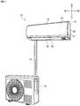
- Fig. 1 is a schematic view of the entire configuration of the air-conditioner 10 according to the first embodiment.
- the air-conditioner 10 has an indoor unit 11 arranged inside a room, and an outdoor unit 12 arranged outside the room.
- the indoor unit 11 sucks in indoor air, and causes the sucked indoor air to pass through the heat exchanger 31 (see Fig. 2 ) to obtain conditioned air subjected to any optional processing of heating, cooling, and dehumidification. Then, the indoor unit 11 blows the obtained conditioned air into the room to air-condition the inside of the room.
- the indoor unit 11 is connected to the outdoor unit 12 through a connection pipe 13 such that refrigerant circulates between the indoor unit 11 and the outdoor unit 12.
- the outdoor unit 12 exchanges heat with the circulating refrigerant.
- the indoor unit 11 includes, in a housing 21 and a decorative frame 22 as an exterior member of the housing 21, structures such as an air blower fan 38 (see Fig. 2 ) and the heat exchanger 31 (see Fig. 2 ).
- the air blower fan 38 is a cross-flow fan configured to send air from an air suction port 24 side to an air blow port 25 side, and sends air heat-exchanged by the heat exchanger 31.
- the heat exchanger 31 is a unit configured to exchange heat with refrigerant.
- a front panel 23 is attached to an upper portion of a front surface of the decorative frame 22 (the exterior member).
- the front panel 23 is a member configured to cover a front surface of the indoor unit 11.
- an upper-to-lower wind deflector 26 is attached to a lower portion of the front surface of the decorative frame 22.
- the upper-to-lower wind deflector 26 is a member configured to define the direction of conditioned air blown from the air blow port 25 in an upper-to-lower direction. It is configured such that the upper-to-lower wind deflector 26 is pivotally supported on the drain pan 39 in the vicinity of a lower end thereof such that an upper portion of the upper-to-lower wind deflector 26 opens/closes in the upper-to-lower direction and is rotated by a not-shown drive unit.
- the indoor unit 11 opens the upper-to-lower wind deflector 26 to form the air blow port 25.
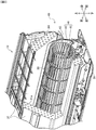
- Fig. 2 is a schematic view of the configuration of the heat exchanger 31 and the peripheral configuration thereof.
- Fig. 3 is a schematic view of a configuration of a fan cleaning device 40 and a peripheral configuration thereof.
- the heat exchanger 31 includes multiple fins 31a for exchanging heat between refrigerant and indoor air, and the multiple hairpin pipes 34 arranged to penetrate the fins 31a and configured such that refrigerant flows in the hairpin pipes 34.
- the heat exchanger 31 has, at each end portion thereof, the side plate 32 forming a side surface. The fins 31a, the hairpin pipes 34, etc. are cooled in the air cooling operation, and condensation water adheres to these components. The condensation water adhering to these components drops and received by the drain pan 39 (see Fig. 2 ).
- the side plate 32 includes the protruding portion 32p.
- the protruding portion 32p protrudes from an outer surface of the side plate 32 to cover at least above the inner end portion of the motor 51 such that condensation water having dropped from the hairpin pipe 34 does not drop onto a later-described motor assembly 50 (specifically, the main body of the motor 51).
- the hairpin pipe 34 is in a curved shape folded back in the vicinity of the outside of the side plate 32.
- the hairpin pipes 34 are coupled to each other through a not-shown pipe.
- the indoor unit 11 When the indoor unit 11 is continuously used, dust etc. adhere to the air blower fan 38.
- the indoor unit 11 has the fan cleaning device 40 configured to clean the air blower fan 38.
- the fan cleaning device 40 has a brush 41, a shaft 45, and the motor assembly 50.
- the brush 41 is a member (a cleaner) configured to contact and clean the air blower fan 38 (see Fig. 2 ).
- the shaft 45 is a member configured to hold the brush 41 (the cleaner).
- the motor assembly 50 is a drive section configured to rotatably drive the shaft 45 in a direction about an axis.
- the brush 41 is configured separately from the shaft 45, and is attachable to or detachable from the shaft 45. Note that it will be described herein that the cleaner of the fan cleaning device 40 is the brush 41. Note that the cleaner of the fan cleaning device 40 may include not only the hairy brush 41 but also an elastic plate such as sponge or elastomer.
- Each of the brush 41 and the shaft 45 is an elongated member.
- the brush 41 and the shaft 45 will be collectively referred to as a "brush 41 etc.”
- the brush 41 etc. are arranged between the fin 31a (see Fig. 2 ) of the heat exchanger 31 and the air blower fan 38 to rotate about the axis.
- the brush 41 etc. are slightly longer than the length of the air blower fan 38 in a longitudinal direction thereof to cover the entire area of the air blower fan 38 in the longitudinal direction thereof.
- the brush 41 etc. are arranged such that both end portions thereof penetrate two side plates 32 arranged at both end portions of the heat exchanger 31.
- Both end portions of the brush 41 etc. are rotatably held by the motor assembly 50 or a not-shown bearing member, for example.
- the brush 41 has multiple fiber portions 42 and a brush base 43.
- the fiber portion 42 is a contact portion configured to contact the air blower fan 38.
- the brush base 43 is a base portion configured to hold each fiber portion 42.
- the motor assembly 50 has the motor 51 configured to rotatably drive the brush 41 etc., and the motor cover 60 configured to cover the periphery of the motor 51.
- a rotary shaft 52 of the motor 51 is directly coupled to the shaft 45, or is indirectly coupled to the shaft 45 through, e.g., a not-shown gear or adaptor. Note that in an example illustrated in Fig. 3 , no spacer 69 illustrated in Fig. 5 is used, but the motor assembly 50 may be attached to the side plate 32 of the heat exchanger 31 through the spacer 69 illustrated in Fig. 5 .
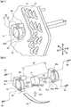
- Fig. 4 illustrates a configuration of the motor assembly 50 of the present embodiment.
- Fig. 4 is an exploded view of the motor assembly 50 of the present embodiment.
- Fig. 4 illustrates an example where the motor assembly 50 is disassembled into the motor 51, a heat insulating member 54, and the motor cover 60.
- the motor 51 has the rotary shaft 52, a lead line 53 drawn from the inside of the main body to the outside, and fixing portions 56 to be fastened to the motor cover 60 through screws 55.
- the heat insulating member 54 is in a tape shape, and is wound around the main body of the motor 51 to cover at least a peripheral surface of the main body of the motor 51 (see a white arrow A11).
- the motor cover 60 has a housing portion 61 configured to house the main body of the motor 51, and fixing portions 66 to be fastened to, e.g., the side plate 32 of the heat exchanger 31 through screws 65.
- a groove 62 for housing the lead line 53 of the motor 51 is formed at a lower portion of an inner peripheral surface of the housing portion 61.
- the motor 51 around which the heat insulating member 54 is wound is housed in the housing portion 61 of the motor cover 60 (see a white arrow A12). In this state, the lead line 53 of the motor 51 is drawn out of the motor cover 60 through the groove 62 of the motor cover 60.
- the motor 51 When the motor 51 is housed in the housing portion 61 of the motor cover 60, the motor 51 and the motor cover 60 are fastened to each other with the screws 55 passing through the fixing portions 56 of the motor 51. Accordingly, the motor assembly 50 is assembled.
- the motor assembly 50 is arranged outside the side plate 32 (see Fig. 3 ) of the heat exchanger 31. Moreover, the motor cover 60 and an attachment target thereof are fastened to each other with the screws 65 passing through the fixing portions 66 of the motor cover 60.
- Fig. 5 illustrates a preferable arrangement location of the motor assembly 50 of the present embodiment.
- Fig. 5 is a schematic view of the preferable arrangement location of the motor assembly 50 of the present embodiment.
- the heat exchanger 31 is cooled in the air cooling operation.
- an outer wall surface of the side plate 32 of the heat exchanger 31 becomes cold. If the motor 51 is directly attached to the outer wall surface of the side plate 32, there is a probability that condensation water adheres to the main body of the motor 51 due to influence of cold air transmitted from the side plate 32. Thus, such a configuration is not preferable.
- the air-conditioner 10 of the present embodiment is configured such that the motor 51 is arranged with an inner end portion 50x of the main body of the motor 51 being separated from the side plate 32.
- the air-conditioner 10 is configured such that, e.g., the spacer 69 or a space is provided between the heat exchanger 31 and the motor assembly 50.
- the air-conditioner 10 is configured such that the motor assembly 50 is attached to the heat exchanger 31 through, e.g., the spacer 69 or the space to separate the inner end portion 50x of the main body of the motor 51 from the side plate 32.
- the air-conditioner 10 is preferably configured such that a sufficient separation distance between the inner end portion 50x of the main body of the motor 51 and the side plate 32 is ensured.
- the motor 51 (the motor assembly 50) is arranged such that the inner end portion 50x of the main body of the motor 51 is positioned on the outside of an outer end portion 34a of a curved portion of the hairpin pipe 34 by, e.g., a distance t1.
- the air-conditioner 10 can reduce adherence of condensation water dropping from the hairpin pipe 34 to the main body of the motor 51.
- the "outside” described herein means a side far from the side plate 32 of the heat exchanger 31.
- the motor 51 (the motor assembly 50) is arranged such that the outer end portion 50y of the motor assembly 50 is positioned on the inside of the inner wall surface of the decorative frame 22 by, e.g., a distance t2.
- the air-conditioner 10 can reduce, upon drive of the motor 51, occurrence of noise due to propagation of vibration of the motor 51 to the decorative frame 22.
- Figs. 6A to 6C illustrate preferable arrangement relationships between the motor 51 of the motor assembly 50 and the drain pan 39 in the present embodiment.
- Figs. 6A to 6C are each schematic views of the preferable arrangement relationships between the motor 51 of the motor assembly 50 and the drain pan 39 in the present embodiment.
- the drain pan 39 may be preferably arranged below the heat exchanger 31 (see Fig. 2 ) and the motor cover 60 to extend outward of an inner end portion (the inner end portion 50x of the motor 51) of the motor cover 60. That is, the drain pan 39 may be arranged below the heat exchanger 31 (see Fig. 2 ) and the motor cover 60, and an end portion of the drain pan 39 may be positioned on the outside of the inner end portion (the inner end portion 50x of the motor 51) of the motor cover 60. With this configuration, the air-conditioner 10 can reliably receive, by the drain pan 39, condensation water adhering to and dropping from the motor cover 60.
- a lower portion of the motor cover 60 may be preferably an inclined portion extending downwardly from an outer end portion side to an inner end portion side.
- the air-conditioner 10 is configured so that a lower surface of the lower portion of the motor cover 60 can function as a flow path R11 of condensation water adhering to the motor cover 60.
- the air-conditioner 10 can guide the condensation water adhering to the motor cover 60 to the drain pan 39, and can efficiently and reliably receive the condensation water by the drain pan 39.
- the entirety of the motor cover 60 may be arranged on the inside of an outer end portion of the drain pan 39.
- the air-conditioner 10 can reliably receive, by the drain pan 39, condensation water adhering to and dropping from the motor cover 60.
- Fig. 7 illustrates a configuration of the brush 41 (the cleaner) used in the present embodiment.
- Fig. 7 is a schematic view of the configuration of the brush 41 (the cleaner).
- the brush 41 has such a structure that a hair implantation region 43a where the fiber portions 42 are implanted is formed across the entire area of the brush base 43.
- the brush 41 is inserted into a housing portion 45a (see Fig. 9 ) provided at the shaft 45, and is attached to the shaft 45. Moreover, the brush 41 can be detached from the shaft 45 by pulling from the housing portion 45a (see Fig. 9 ).
- the shaft 45 is arranged inside the indoor unit 11 such that both end portions thereof penetrate two side plates 32 arranged at both end portions of the heat exchanger 31. Note that Fig. 7 illustrates only the side plate 32 arranged on a left side. Both end portions of the shaft 45 are rotatably held by, e.g., the motor 51 (the motor assembly 50) or the not-shown bearing member.
- a case where the not-shown bearing member arranged on a right side of the shaft 45 is detached and the brush 41 is inserted into the housing portion 45a (see Fig. 9 ) from the right side to the left side of the shaft 45 is illustrated by way of example.
- the brush 41 can be inserted into the housing portion 45a (see Fig. 9 ) from the left side to the right side of the shaft 45 by detachment of the motor 51 (the motor assembly 50) arranged on the left side of the shaft 45.
- a strength for holding stiffness is set such that the brush 41 is easily inserted into the housing portion 45a (see Fig. 9 ) of the shaft 45.
- the brush 41 can be easily replaced by pulling from or insertion into the side of the shaft 45.
- the brush base 43 (the base portion) of the brush 41 (the cleaner) may have elasticity so that the brush base 43 can be curved.
- the fan cleaning device 40 is configured such that the brush 41 can be attached (inserted) to or detached (drawn) from the shaft 45 with the brush base 43 of the brush 41 being curved. That is, for the fan cleaning device 40, a replacement process can be performed with the brush base 43 being curved.
- Such a fan cleaning device 40 is configured so that the process of replacing the brush 41 in a narrow space (e.g., the process of replacing the brush 41 in the air-conditioner 10 placed in the vicinity of an end of the room) can be facilitated.
- the brush 41 illustrated in Fig. 7 is configured such that the hair implantation region 43a is formed across the entire area of the brush base 43. Thus, the fiber portions 42 in the vicinity of the end portion contact the side plate 32 of the heat exchanger 31.
- Use of the brush 41 illustrated in Fig. 7 in the fan cleaning device 40 applies a load onto the brush 41 or easily contaminates the brush 41 when the brush 41 is, upon cleaning of the air blower fan 38, rotated to cause the brush 41 to contact the air blower fan 38.
- the fan cleaning device 40 may use, for example, a brush 41A illustrated in Figs. 8 to 10 instead of the brush 41.
- Figs. 8 to 10 illustrate a configuration of the brush 41A as another cleaner used in the present embodiment.
- Fig. 8 is a schematic view of the configuration of the brush 41A.
- Figs. 9 and 10 are each perspective views of a main portion of the configuration of the brush 41A.
- the brush 41A has, in the brush base 43, the hair implantation region 43a where the fiber portions 42 are implanted, and a hair non-implantation region 43b where no fiber portions 42 are implanted.
- the hair implantation region 43a is formed at other portions than one or both end portions of the brush base 43.
- the hair non-implantation region 43b is formed at one or both end portions of the brush base 43.
- the hair non-implantation region 43b is provided to extend from the outside to the inside of the side plate 32.
- the brush 41A is inserted into the housing portion 45a provided at the shaft 45, and is attached to the shaft 45. Moreover, the brush 41A can be detached from the shaft 45 by pulling from the housing portion 45a.
- the brush 41 has, at the end portion of the brush base 43, a handle portion 43c for gripping the brush base 43 with a human hand.
- the handle portion 43c is a portion more closer to the end portion of the brush base 43 in the hair non-implantation region 43b formed at the end portion of the brush base 43. As illustrated in Figs. 8 and 10 , the handle portion 43c protrudes outward of the end portion of the shaft 45 in a state in which the brush 41A is attached to the shaft 45.
- the brush 41A can be easily detached from the shaft 45 by gripping of the handle portion 43c with the human hand. In this state, an operator operates the handle portion 43c to manually change the direction of the brush 41A, so that the brush 41A can be replaced at a position not contacting the air blower fan 38 and the heat exchanger 31.
- the brush base 43 of the brush 41A may have elasticity to curve as in the brush base 43 of the brush 41 illustrated in Fig. 7 .
- the fan cleaning device 40 is configured such that when the brush 41A is rotated upon cleaning of the air blower fan 38, the fiber portions 42 do not contact the side plate 32 of the heat exchanger 31 at one or both end portions of the brush 41A. Thus, when the brush 41A is rotated, the fan cleaning device 40 can reduce a load on the brush 41A. Moreover, the fan cleaning device 40 can reduce contamination of the brush 41A.
- the fan cleaning device 40 is configured such that the handle portion 43c is provided at the brush base 43, and therefore, the brush 41 can be easily pulled out from a space at the side of the heat exchanger 31.
- the main body of the motor 51 for brush drive is arranged on the outside (the left side in Fig. 5 ) with respect to the outer end portion 34a of the curved portion provided at the hairpin pipe 34 of the heat exchanger 31.
- the air-conditioner 10 can reduce generation of condensation water and adherence of the condensation water to the motor 51 due to excessive cooling of the motor 51 due to the influence of cold air transmitted from the side plate 32 of the heat exchanger 31.
- the motor 51 is arranged on the outside with respect to the outer end portion 34a of the curved portion of the hairpin pipe 34, and therefore, dropping of condensation water adhering to and dropping from the hairpin pipe 34 onto the motor 51 can be reduced.
- the motor cover 60 includes a single member.
- a second embodiment provides a motor assembly 50A (see Figs. 11 to 13 ) configured such that a motor cover 60 includes multiple (e.g., two) members.
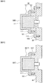
- Fig. 11 is a schematic view of the configuration of the motor assembly 50A.
- Fig. 12 is an exploded view of the configuration of the motor assembly 50A.
- Fig. 13 is a schematic sectional view of an internal structure of the motor assembly 50A.
- the motor assembly 50A of the second embodiment is, as compared to the motor assembly 50 (see Fig. 3 ) of the first embodiment, different in that the motor cover 60 includes two members of a first motor cover 71 and a second motor cover 72.
- the first motor cover 71 is a member on a side (the outside) far from a side plate 32 of a heat exchanger 31
- the second motor cover 72 is a member on a side (the inside) closer to the side plate 32 of the heat exchanger 31.
- no spacer 69 illustrated in Fig. 5 is used, but the motor assembly 50A may be attached to the side plate 32 of the heat exchanger 31 through the spacer 69 illustrated in Fig. 5 .
- the first motor cover 71 has a housing portion 61 for housing an outer portion of a main body of a motor 51, and fixing portions 66 to be fastened to, e.g., the side plate 32 of the heat exchanger 31 with screws 65.
- a groove 62 for housing a lead line 53 of the motor 51 is formed at a lower portion of an inner peripheral surface of the housing portion 61.
- the groove 62 is formed not to penetrate an inner wall surface (a left wall surface in Fig. 12 ) of the housing portion 61.
- the second motor cover 72 has a housing portion 61a for housing an inner portion of the main body of the motor 51, and fixing portions 66a to be fastened to the first motor cover 71 with screws 55.
- a groove 62a for housing the lead line 53 of the motor 51 is formed at a lower portion of an inner peripheral surface of the housing portion 61a.
- the groove 62a is formed to penetrate an inner wall surface (a right wall surface in Fig. 12 ) of the housing portion 61a.
- a structure is employed, in which the groove 62 of the first motor cover 71 and the groove 62a of the second motor cover 72 communicate with each other.
- the lead line 53 of the motor 51 is drawn out of the motor cover 60 through the groove 62 of the first motor cover 71 and the groove 62a of the second motor cover 72.
- the motor assembly 50A is assembled as follows. First, a tape-shaped heat insulating member 54 is wound around the outer periphery of the main body of the motor 51 (see a white arrow A21). Next, the motor 51 around which the heat insulating member 54 is wound is housed in the housing portion 61 of the first motor cover 71 (see a white arrow A22). In this state, the lead line 53 of the motor 51 is drawn out of the first motor cover 71 through the groove 62 of the first motor cover 71. Next, the motor 51 is housed in the housing portion 61a of the second motor cover 72 (see a white arrow A23). In this state, the lead line 53 of the motor 51 is drawn out of the second motor cover 72 through the groove 62a of the second motor cover 72. In this manner, the motor assembly 50A is assembled.
- Fig. 13 schematically illustrates a sectional structure of the motor assembly 50A as viewed from the side. Note that in Fig. 13 , the lead line 53 of the motor 51 is not shown. As illustrated in Fig. 13 , the motor assembly 50A seals the entire circumference of the motor 51 by the first motor cover 71 and the second motor cover 72, and in this state, is attached to the side plate 32. Such a motor assembly 50A can efficiently reduce adherence of condensation water to the motor 51.
- adherence of condensation water to the main body of the motor 51 of a fan cleaning device 40 can be efficiently reduced as in the first embodiment.
- the present invention is not limited to those including all components described above.
- other components may be added to a certain component, and some components may be changed to other components.
- some components may be omitted.
- motor assembly 50A (see Figs. 11 to 13 ) of the second embodiment described above may be, for example, modified as in first to fourth variations illustrated in Figs. 14 to 17 .
- Fig. 14 is a schematic view of an internal structure of a motor assembly 50B of the first variation. As illustrated in Fig. 14 , the motor assembly 50B according to the first variation is different on the following points as compared to the motor assembly 50A (see Figs. 11 to 13 ) of the second embodiment.
- such a motor assembly 50B can efficiently reduce adherence of condensation water to the main body of the motor 51 of the fan cleaning device 40.
- the motor 51 is housed in the first motor cover 71 and the second motor cover 72.
- Fig. 15 is a schematic view of an internal structure of a motor assembly 50C of the second variation. As illustrated in Fig. 15 , the motor assembly 50C of the second variation is different on the following points as compared to the motor assembly 50B (see Fig. 14 ) of the first variation.
- such a motor assembly 50C of the second variation can reduce the number of components by the second motor cover 72.
- the motor cover 60 and the contact portion 32Z may preferably have such a structure that the motor cover 60 and the contact portion 32Z covers at least above the entirety of the main body of the motor 51.
- Fig. 16 is a schematic view of an internal structure of a motor assembly 50D of the third variation. As illustrated in Fig. 16 , the motor assembly 50D of the third variation is different on the following points as compared to the motor assembly 50B (see Fig. 14 ) of the first variation.
- Such a motor assembly 50D of the third variation allows the cover portions 67 to function as a dew guard section configured to reduce adherence of condensation water to the motor 51.
- the motor assembly 50D of the third variation can efficiently reduce adherence of condensation water to the main body of the motor 51 of the fan cleaning device 40.
- the cover portions 67 function as a positioning section configured to contact the side plate 32 to determine the position of the motor assembly 50D. With this configuration, the motor assembly 50D can be stably arranged at a desired position.
- Fig. 17 is a schematic view of an internal structure of a motor assembly 50E of the fourth variation. As illustrated in Fig. 17 , the motor assembly 50E of the fourth variation is different on the following points as compared to the motor assembly 50D (see Fig. 16 ) of the third variation.
- Such a motor assembly 50E of the fourth variation can cause the lap structure 68 to function as a dew guard section configured to reduce adherence of condensation water to the motor 51.
- the motor assembly 50E of the fourth variation can efficiently reduce adherence of condensation water to the main body of the motor 51 of the fan cleaning device 40.
Landscapes
- Engineering & Computer Science (AREA)
- Chemical & Material Sciences (AREA)
- Combustion & Propulsion (AREA)
- Mechanical Engineering (AREA)
- General Engineering & Computer Science (AREA)
- Devices For Blowing Cold Air, Devices For Blowing Warm Air, And Means For Preventing Water Condensation In Air Conditioning Units (AREA)
- Structures Of Non-Positive Displacement Pumps (AREA)
- Air-Conditioning Room Units, And Self-Contained Units In General (AREA)
- Motor Or Generator Frames (AREA)
- Air Filters, Heat-Exchange Apparatuses, And Housings Of Air-Conditioning Units (AREA)
- Other Air-Conditioning Systems (AREA)
Abstract
Description
- The present invention relates to an air-conditioner.
- Generally, for an air-conditioner including an air blower fan, more dust adheres to the air blower fan as use time increases. Thus, the air volume of the air-conditioner might decrease, or power consumption of the air-conditioner might increase. Moreover, in some cases, fungi etc. are caused due to adherence of the dust in the air-conditioner, leading to insanitation. For these reasons, an air-conditioner including a fan cleaning device configured to remove dust adhering to an air blower fan to clean the air blower fan has been provided (see, e.g., Patent Document 1). The air-conditioner described in Patent Document 1 includes the fan cleaning device and a control device configured to control the fan cleaning device, and has a normal operation mode for blowing conditioned air into a room and a fan cleaning mode for rotating a fan at low speed and movably operating the fan cleaning device. The fan cleaning device includes a cleaner configured to contact the fan in the fan cleaning operation mode, and is configured to movably operate the cleaner to a position retreated from the fan in the normal operation mode.
- The fan cleaning device rotatably drives the cleaner by a motor. It is efficient when the motor is arranged at a location close to a rotary shaft of the cleaner. For this reason, air-conditioners include one configured such that a motor of a fan cleaning device is attached to a location close to a rotary shaft of a cleaner at a side surface (specifically, an outer wall surface of a side plate forming the side surface of a heat exchanger) of the heat exchanger.
- Patent Document 1: Japanese Patent No.
4046755 - However, as described below, in the typical air-conditioner, the motor of the fan cleaning device is arranged at such a location, and therefore, there is a probability that condensation water adheres to the motor and a motor failure rate increases.
- For example, in the air-conditioner, the heat exchanger is cooled in air cooling operation. Thus, the outer wall surface of the side plate forming the side surface of the heat exchanger becomes cold. The motor of the typical air-conditioner is attached to the outer wall surface of the side plate. Thus, there is a probability that due to excessive cooling of the motor due to influence of cold air transmitted from the side plate, condensation water is caused and adheres to the motor. Consequently, there is a probability that the motor failure rate increases.
- Moreover, e.g., a hairpin pipe projecting outward is arranged at the side plate of the heat exchanger. In the air-conditioner, refrigerant flows in the hairpin pipe in the air cooling operation, and therefore, condensation water adheres to the hairpin pipe. In the typical air-conditioner, the motor is arranged right below the hairpin pipe, and therefore, the condensation water might drop from the hairpin pipe onto the motor. Thus, there is a probability that the motor failure rate increases.
- The present invention has been made for solving the above-described problems, and a main object of the present invention is to provide an air-conditioner configured to reduce adherence of condensation water to a motor of a fan cleaning device.
- For accomplishing the above-described object, the present invention relates to an air-conditioner including a heat exchanger, an air blower fan, a cleaner configured to clean the air blower fan, and a motor arranged on the outside with respect to a side plate of the heat exchanger and configured to drive the cleaner. A main body of the motor is arranged on the outside with respect to an outer end portion of a curved portion provided at a hairpin pipe of the heat exchanger.
- Other techniques will be described later.
- According to the present invention, adherence of condensation water to the motor of a fan cleaning device can be reduced.
-
-
Fig. 1 is a schematic view of an entire configuration of an air-conditioner according to a first embodiment. -
Fig. 2 is a schematic view of a configuration of a heat exchanger and a peripheral configuration thereof in an indoor unit of the air-conditioner according to the first embodiment. -
Fig. 3 is a schematic view of a configuration of a fan cleaning device according to the first embodiment and a peripheral configuration thereof. -
Fig. 4 is an exploded view of a configuration of a motor assembly of the fan cleaning device according to the first embodiment. -
Fig. 5 is a schematic view of a preferable arrangement location of the motor assembly of the first embodiment. -
Fig. 6A is a schematic view (1) of a preferable arrangement relationship between a motor of the motor assembly and a drain pan in the first embodiment. -
Fig. 6B is a schematic view (2) of the preferable arrangement relationship between the motor of the motor assembly and the drain pan in the first embodiment. -
Fig. 6C is a schematic view (3) of the preferable arrangement relationship between the motor of the motor assembly and the drain pan in the first embodiment; -
Fig. 7 is a schematic view of a configuration of a cleaner used in the first embodiment. -
Fig. 8 is a schematic view of a configuration of another cleaner used in the first embodiment. -
Fig. 9 is a perspective view (1) of a main portion of the configuration of another cleaner used in the first embodiment. -
Fig. 10 is a perspective view (2) of the main portion of the configuration of another cleaner used in the first embodiment. -
Fig. 11 is a schematic view of a configuration of a motor assembly according to a second embodiment. -
Fig. 12 is an exploded view of the configuration of the motor assembly according to the second embodiment. -
Fig. 13 is a schematic view of an internal structure of the motor assembly of the second embodiment. -
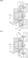
Fig. 14 is a schematic view of an internal structure of a motor assembly of a first variation. -
Fig. 15 is a schematic view of an internal structure of a motor assembly of a second variation. -
Fig. 16 is a schematic view of an internal structure of a motor assembly of a third variation. -
Fig. 17 is a schematic view of an internal structure of a motor assembly of a fourth variation. - Hereinafter, embodiments (hereinafter referred to as "present embodiments") of the present invention will be described in detail with reference to the drawings. Note that each figure is merely schematically illustrated to such an extent that the present invention can be fully understood. Thus, the present invention is not limited only to illustrated examples. Moreover, in each figure, the same reference numerals are used to represent common components or similar components, and overlapping description thereof will be omitted.
- A first embodiment is intended to provide the following air-
conditioner 10. - (1) As illustrated in
Fig. 5 , the air-conditioner 10 according to the first embodiment is configured such that amotor 51 is separated from aside plate 32 of aheat exchanger 31 to prevent generation of condensation water by excessive cooling of themotor 51 due to influence of cold air transmitted from theside plate 32 and adherence of the condensation water to themotor 51. - (2) As illustrated in
Fig. 5 , the air-conditioner 10 according to the first embodiment is configured such that themotor 51 is shifted outward (leftward inFig. 5 ) from a location right below ahairpin pipe 34 to prevent condensation water dropping from thehairpin pipe 34 from dropping onto a main body of themotor 51. - (3) As illustrated in
Fig. 3 , the air-conditioner 10 according to the first embodiment is configured such that the main body of themotor 51 is covered with amotor cover 60 to prevent dropping of condensation water onto the main body of themotor 51 and condensation and adherence of condensation water to the main body of themotor 51. Moreover, as illustrated inFig. 3 , the air-conditioner 10 according to the first embodiment is configured such that a protrudingportion 32p covers above an inner end portion of themotor 51 to prevent dropping and adherence of condensation water onto the main body of themotor 51. Further, as illustrated inFigs. 6A to 6C , the air-conditioner 10 according to the first embodiment is configured so that condensation water adhering to and dropping from themotor cover 60 can be reliably received by adrain pan 39. - Hereinafter, an entire configuration of the air-
conditioner 10 according to the first embodiment will be described with reference toFig. 1. Fig. 1 is a schematic view of the entire configuration of the air-conditioner 10 according to the first embodiment. - As illustrated in
Fig. 1 , the air-conditioner 10 has anindoor unit 11 arranged inside a room, and anoutdoor unit 12 arranged outside the room. - The
indoor unit 11 sucks in indoor air, and causes the sucked indoor air to pass through the heat exchanger 31 (seeFig. 2 ) to obtain conditioned air subjected to any optional processing of heating, cooling, and dehumidification. Then, theindoor unit 11 blows the obtained conditioned air into the room to air-condition the inside of the room. Theindoor unit 11 is connected to theoutdoor unit 12 through aconnection pipe 13 such that refrigerant circulates between theindoor unit 11 and theoutdoor unit 12. Theoutdoor unit 12 exchanges heat with the circulating refrigerant. - The
indoor unit 11 includes, in ahousing 21 and adecorative frame 22 as an exterior member of thehousing 21, structures such as an air blower fan 38 (seeFig. 2 ) and the heat exchanger 31 (seeFig. 2 ). Theair blower fan 38 is a cross-flow fan configured to send air from anair suction port 24 side to anair blow port 25 side, and sends air heat-exchanged by theheat exchanger 31. Theheat exchanger 31 is a unit configured to exchange heat with refrigerant. - In an example illustrated in
Fig. 1 , afront panel 23 is attached to an upper portion of a front surface of the decorative frame 22 (the exterior member). Thefront panel 23 is a member configured to cover a front surface of theindoor unit 11. Moreover, an upper-to-lower wind deflector 26 is attached to a lower portion of the front surface of thedecorative frame 22. - The upper-to-
lower wind deflector 26 is a member configured to define the direction of conditioned air blown from theair blow port 25 in an upper-to-lower direction. It is configured such that the upper-to-lower wind deflector 26 is pivotally supported on thedrain pan 39 in the vicinity of a lower end thereof such that an upper portion of the upper-to-lower wind deflector 26 opens/closes in the upper-to-lower direction and is rotated by a not-shown drive unit. Theindoor unit 11 opens the upper-to-lower wind deflector 26 to form theair blow port 25. - Hereinafter, a configuration of the
heat exchanger 31 and a peripheral configuration thereof in theindoor unit 11 of the air-conditioner 10 will be described with reference toFigs. 2 and3 .Fig. 2 is a schematic view of the configuration of theheat exchanger 31 and the peripheral configuration thereof.Fig. 3 is a schematic view of a configuration of afan cleaning device 40 and a peripheral configuration thereof. - As illustrated in
Fig. 2 , structures such as the above-describedair blower fan 38, the above-describedheat exchanger 31, and thedrain pan 39 configured to receive condensation water adhering to and dropping from theheat exchanger 31 in air cooling operation are arranged inside theindoor unit 11. Theheat exchanger 31 includesmultiple fins 31a for exchanging heat between refrigerant and indoor air, and themultiple hairpin pipes 34 arranged to penetrate thefins 31a and configured such that refrigerant flows in thehairpin pipes 34. As illustrated inFig. 3 , theheat exchanger 31 has, at each end portion thereof, theside plate 32 forming a side surface. Thefins 31a, thehairpin pipes 34, etc. are cooled in the air cooling operation, and condensation water adheres to these components. The condensation water adhering to these components drops and received by the drain pan 39 (seeFig. 2 ). - Note that the
side plate 32 includes the protrudingportion 32p. The protrudingportion 32p protrudes from an outer surface of theside plate 32 to cover at least above the inner end portion of themotor 51 such that condensation water having dropped from thehairpin pipe 34 does not drop onto a later-described motor assembly 50 (specifically, the main body of the motor 51). Note that thehairpin pipe 34 is in a curved shape folded back in the vicinity of the outside of theside plate 32. Thehairpin pipes 34 are coupled to each other through a not-shown pipe. - When the
indoor unit 11 is continuously used, dust etc. adhere to theair blower fan 38. Thus, as illustrated inFigs. 2 and3 , theindoor unit 11 has thefan cleaning device 40 configured to clean theair blower fan 38. - As illustrated in
Fig. 3 , thefan cleaning device 40 has abrush 41, ashaft 45, and themotor assembly 50. - The
brush 41 is a member (a cleaner) configured to contact and clean the air blower fan 38 (seeFig. 2 ). - The
shaft 45 is a member configured to hold the brush 41 (the cleaner). - The
motor assembly 50 is a drive section configured to rotatably drive theshaft 45 in a direction about an axis. - The
brush 41 is configured separately from theshaft 45, and is attachable to or detachable from theshaft 45. Note that it will be described herein that the cleaner of thefan cleaning device 40 is thebrush 41. Note that the cleaner of thefan cleaning device 40 may include not only thehairy brush 41 but also an elastic plate such as sponge or elastomer. - Each of the
brush 41 and theshaft 45 is an elongated member. Hereinafter, thebrush 41 and theshaft 45 will be collectively referred to as a "brush 41 etc." Thebrush 41 etc. are arranged between thefin 31a (seeFig. 2 ) of theheat exchanger 31 and theair blower fan 38 to rotate about the axis. Thebrush 41 etc. are slightly longer than the length of theair blower fan 38 in a longitudinal direction thereof to cover the entire area of theair blower fan 38 in the longitudinal direction thereof. Thebrush 41 etc. are arranged such that both end portions thereof penetrate twoside plates 32 arranged at both end portions of theheat exchanger 31. - Both end portions of the
brush 41 etc. are rotatably held by themotor assembly 50 or a not-shown bearing member, for example. - The
brush 41 hasmultiple fiber portions 42 and abrush base 43. Thefiber portion 42 is a contact portion configured to contact theair blower fan 38. Thebrush base 43 is a base portion configured to hold eachfiber portion 42. - The
motor assembly 50 has themotor 51 configured to rotatably drive thebrush 41 etc., and themotor cover 60 configured to cover the periphery of themotor 51. Arotary shaft 52 of themotor 51 is directly coupled to theshaft 45, or is indirectly coupled to theshaft 45 through, e.g., a not-shown gear or adaptor. Note that in an example illustrated inFig. 3 , nospacer 69 illustrated inFig. 5 is used, but themotor assembly 50 may be attached to theside plate 32 of theheat exchanger 31 through thespacer 69 illustrated inFig. 5 . -
Fig. 4 illustrates a configuration of themotor assembly 50 of the present embodiment.Fig. 4 is an exploded view of themotor assembly 50 of the present embodiment.Fig. 4 illustrates an example where themotor assembly 50 is disassembled into themotor 51, aheat insulating member 54, and themotor cover 60. - In the example illustrated in
Fig. 4 , themotor 51 has therotary shaft 52, alead line 53 drawn from the inside of the main body to the outside, and fixingportions 56 to be fastened to themotor cover 60 throughscrews 55. Theheat insulating member 54 is in a tape shape, and is wound around the main body of themotor 51 to cover at least a peripheral surface of the main body of the motor 51 (see a white arrow A11). - The
motor cover 60 has ahousing portion 61 configured to house the main body of themotor 51, and fixingportions 66 to be fastened to, e.g., theside plate 32 of theheat exchanger 31 throughscrews 65. Agroove 62 for housing thelead line 53 of themotor 51 is formed at a lower portion of an inner peripheral surface of thehousing portion 61. - The
motor 51 around which theheat insulating member 54 is wound is housed in thehousing portion 61 of the motor cover 60 (see a white arrow A12). In this state, thelead line 53 of themotor 51 is drawn out of themotor cover 60 through thegroove 62 of themotor cover 60. - When the
motor 51 is housed in thehousing portion 61 of themotor cover 60, themotor 51 and themotor cover 60 are fastened to each other with thescrews 55 passing through the fixingportions 56 of themotor 51. Accordingly, themotor assembly 50 is assembled. Themotor assembly 50 is arranged outside the side plate 32 (seeFig. 3 ) of theheat exchanger 31. Moreover, themotor cover 60 and an attachment target thereof are fastened to each other with thescrews 65 passing through the fixingportions 66 of themotor cover 60. -
Fig. 5 illustrates a preferable arrangement location of themotor assembly 50 of the present embodiment.Fig. 5 is a schematic view of the preferable arrangement location of themotor assembly 50 of the present embodiment. - For example, in the air-
conditioner 10, theheat exchanger 31 is cooled in the air cooling operation. Thus, an outer wall surface of theside plate 32 of theheat exchanger 31 becomes cold. If themotor 51 is directly attached to the outer wall surface of theside plate 32, there is a probability that condensation water adheres to the main body of themotor 51 due to influence of cold air transmitted from theside plate 32. Thus, such a configuration is not preferable. - For this reason, as illustrated in
Fig. 5 , the air-conditioner 10 of the present embodiment is configured such that themotor 51 is arranged with aninner end portion 50x of the main body of themotor 51 being separated from theside plate 32. Specifically, the air-conditioner 10 is configured such that, e.g., thespacer 69 or a space is provided between theheat exchanger 31 and themotor assembly 50. Note that in an example illustrated inFig. 5 , the air-conditioner 10 is configured such that themotor assembly 50 is attached to theheat exchanger 31 through, e.g., thespacer 69 or the space to separate theinner end portion 50x of the main body of themotor 51 from theside plate 32. - Moreover, if the
inner end portion 50x of the main body of themotor 51 is separated from theside plate 32, when such a separation distance is not enough, there is a probability that condensation water adhering to thehairpin pipe 34 drops onto themotor assembly 50. - In this case, dropping of condensation water onto the vicinity of a mating surface 50z between the
motor assembly 50 and thespacer 69 in the air-conditioner 10 is not specifically preferable due to the following reasons. For example, the mating surface 50z is normally sealed. However, if a clearance is caused at the mating surface 50z, there is a probability that condensation water enters the mating surface 50z along such a clearance and reaches the main body of themotor 51. Thus, there is a probability that the condensation water adheres to the main body of themotor 51. For these reasons, dropping of condensation water onto the vicinity of the mating surface 50z is not preferable. Thus, the air-conditioner 10 is preferably configured such that a sufficient separation distance between theinner end portion 50x of the main body of themotor 51 and theside plate 32 is ensured. - Thus, as illustrated in
Fig. 5 , in the air-conditioner 10 of the present embodiment, the motor 51 (the motor assembly 50) is arranged such that theinner end portion 50x of the main body of themotor 51 is positioned on the outside of anouter end portion 34a of a curved portion of thehairpin pipe 34 by, e.g., a distance t1. Thus, the air-conditioner 10 can reduce adherence of condensation water dropping from thehairpin pipe 34 to the main body of themotor 51. Note that the "outside" described herein means a side far from theside plate 32 of theheat exchanger 31. - Note that if an extremely-large separation distance between the
inner end portion 50x of the main body of themotor 51 and theside plate 32 is provided in the air-conditioner 10, anouter end portion 50y of themotor assembly 50 contacts an inner wall surface of thedecorative frame 22. Thus, upon drive of themotor 51, vibration of themotor 51 is propagated to thedecorative frame 22, leading to the probability that noise is caused. - For this reason, as illustrated in
Fig. 5 , in the air-conditioner 10 of the present embodiment, the motor 51 (the motor assembly 50) is arranged such that theouter end portion 50y of themotor assembly 50 is positioned on the inside of the inner wall surface of thedecorative frame 22 by, e.g., a distance t2. Thus, the air-conditioner 10 can reduce, upon drive of themotor 51, occurrence of noise due to propagation of vibration of themotor 51 to thedecorative frame 22. -
Figs. 6A to 6C illustrate preferable arrangement relationships between themotor 51 of themotor assembly 50 and thedrain pan 39 in the present embodiment.Figs. 6A to 6C are each schematic views of the preferable arrangement relationships between themotor 51 of themotor assembly 50 and thedrain pan 39 in the present embodiment. - As illustrated in
Figs. 6A and 6B , thedrain pan 39 may be preferably arranged below the heat exchanger 31 (seeFig. 2 ) and themotor cover 60 to extend outward of an inner end portion (theinner end portion 50x of the motor 51) of themotor cover 60. That is, thedrain pan 39 may be arranged below the heat exchanger 31 (seeFig. 2 ) and themotor cover 60, and an end portion of thedrain pan 39 may be positioned on the outside of the inner end portion (theinner end portion 50x of the motor 51) of themotor cover 60. With this configuration, the air-conditioner 10 can reliably receive, by thedrain pan 39, condensation water adhering to and dropping from themotor cover 60. - Moreover, as illustrated in
Fig. 6B , a lower portion of themotor cover 60 may be preferably an inclined portion extending downwardly from an outer end portion side to an inner end portion side. With this configuration, the air-conditioner 10 is configured so that a lower surface of the lower portion of themotor cover 60 can function as a flow path R11 of condensation water adhering to themotor cover 60. As a result, the air-conditioner 10 can guide the condensation water adhering to themotor cover 60 to thedrain pan 39, and can efficiently and reliably receive the condensation water by thedrain pan 39. - Alternatively, as illustrated in
Fig. 6C , the entirety of themotor cover 60 may be arranged on the inside of an outer end portion of thedrain pan 39. With this configuration, the air-conditioner 10 can reliably receive, by thedrain pan 39, condensation water adhering to and dropping from themotor cover 60. -
Fig. 7 illustrates a configuration of the brush 41 (the cleaner) used in the present embodiment.Fig. 7 is a schematic view of the configuration of the brush 41 (the cleaner). - As illustrated in
Fig. 7 , thebrush 41 has such a structure that ahair implantation region 43a where thefiber portions 42 are implanted is formed across the entire area of thebrush base 43. - The
brush 41 is inserted into ahousing portion 45a (seeFig. 9 ) provided at theshaft 45, and is attached to theshaft 45. Moreover, thebrush 41 can be detached from theshaft 45 by pulling from thehousing portion 45a (seeFig. 9 ). - The
shaft 45 is arranged inside theindoor unit 11 such that both end portions thereof penetrate twoside plates 32 arranged at both end portions of theheat exchanger 31. Note thatFig. 7 illustrates only theside plate 32 arranged on a left side. Both end portions of theshaft 45 are rotatably held by, e.g., the motor 51 (the motor assembly 50) or the not-shown bearing member. - In an example illustrated in
Fig. 7 , a case where the not-shown bearing member arranged on a right side of theshaft 45 is detached and thebrush 41 is inserted into thehousing portion 45a (seeFig. 9 ) from the right side to the left side of theshaft 45 is illustrated by way of example. However, thebrush 41 can be inserted into thehousing portion 45a (seeFig. 9 ) from the left side to the right side of theshaft 45 by detachment of the motor 51 (the motor assembly 50) arranged on the left side of theshaft 45. - For the
brush 41, a strength for holding stiffness is set such that thebrush 41 is easily inserted into thehousing portion 45a (seeFig. 9 ) of theshaft 45. With this configuration, thebrush 41 can be easily replaced by pulling from or insertion into the side of theshaft 45. Note that the brush base 43 (the base portion) of the brush 41 (the cleaner) may have elasticity so that thebrush base 43 can be curved. With this configuration, thefan cleaning device 40 is configured such that thebrush 41 can be attached (inserted) to or detached (drawn) from theshaft 45 with thebrush base 43 of thebrush 41 being curved. That is, for thefan cleaning device 40, a replacement process can be performed with thebrush base 43 being curved. Such afan cleaning device 40 is configured so that the process of replacing thebrush 41 in a narrow space (e.g., the process of replacing thebrush 41 in the air-conditioner 10 placed in the vicinity of an end of the room) can be facilitated. - The
brush 41 illustrated inFig. 7 is configured such that thehair implantation region 43a is formed across the entire area of thebrush base 43. Thus, thefiber portions 42 in the vicinity of the end portion contact theside plate 32 of theheat exchanger 31. Use of thebrush 41 illustrated inFig. 7 in thefan cleaning device 40 applies a load onto thebrush 41 or easily contaminates thebrush 41 when thebrush 41 is, upon cleaning of theair blower fan 38, rotated to cause thebrush 41 to contact theair blower fan 38. - For this reason, the
fan cleaning device 40 may use, for example, abrush 41A illustrated inFigs. 8 to 10 instead of thebrush 41.Figs. 8 to 10 illustrate a configuration of thebrush 41A as another cleaner used in the present embodiment.Fig. 8 is a schematic view of the configuration of thebrush 41A.Figs. 9 and 10 are each perspective views of a main portion of the configuration of thebrush 41A. - As illustrated in
Figs. 8 and10 , thebrush 41A has, in thebrush base 43, thehair implantation region 43a where thefiber portions 42 are implanted, and ahair non-implantation region 43b where nofiber portions 42 are implanted. Thehair implantation region 43a is formed at other portions than one or both end portions of thebrush base 43. Thehair non-implantation region 43b is formed at one or both end portions of thebrush base 43. Thehair non-implantation region 43b is provided to extend from the outside to the inside of theside plate 32. - As illustrated in
Fig. 9 , thebrush 41A is inserted into thehousing portion 45a provided at theshaft 45, and is attached to theshaft 45. Moreover, thebrush 41A can be detached from theshaft 45 by pulling from thehousing portion 45a. - As illustrated in
Figs. 8 and10 , thebrush 41 has, at the end portion of thebrush base 43, ahandle portion 43c for gripping thebrush base 43 with a human hand. - The
handle portion 43c is a portion more closer to the end portion of thebrush base 43 in thehair non-implantation region 43b formed at the end portion of thebrush base 43. As illustrated inFigs. 8 and10 , thehandle portion 43c protrudes outward of the end portion of theshaft 45 in a state in which thebrush 41A is attached to theshaft 45. - In the
fan cleaning device 40, thebrush 41A can be easily detached from theshaft 45 by gripping of thehandle portion 43c with the human hand. In this state, an operator operates thehandle portion 43c to manually change the direction of thebrush 41A, so that thebrush 41A can be replaced at a position not contacting theair blower fan 38 and theheat exchanger 31. Note that thebrush base 43 of thebrush 41A may have elasticity to curve as in thebrush base 43 of thebrush 41 illustrated inFig. 7 . - The
fan cleaning device 40 is configured such that when thebrush 41A is rotated upon cleaning of theair blower fan 38, thefiber portions 42 do not contact theside plate 32 of theheat exchanger 31 at one or both end portions of thebrush 41A. Thus, when thebrush 41A is rotated, thefan cleaning device 40 can reduce a load on thebrush 41A. Moreover, thefan cleaning device 40 can reduce contamination of thebrush 41A. - Further, the
fan cleaning device 40 is configured such that thehandle portion 43c is provided at thebrush base 43, and therefore, thebrush 41 can be easily pulled out from a space at the side of theheat exchanger 31. - (1) As illustrated in
Fig. 5 , in the air-conditioner 10 of the present embodiment, the main body of themotor 51 for brush drive is arranged on the outside (the left side inFig. 5 ) with respect to theouter end portion 34a of the curved portion provided at thehairpin pipe 34 of theheat exchanger 31. - In such an air-
conditioner 10, a space can be ensured between theouter end portion 34a of the curved portion provided at thehairpin pipe 34 of theheat exchanger 31 and themotor 51. With this configuration, the air-conditioner 10 can reduce generation of condensation water and adherence of the condensation water to themotor 51 due to excessive cooling of themotor 51 due to the influence of cold air transmitted from theside plate 32 of theheat exchanger 31. - Moreover, in the air-
conditioner 10, themotor 51 is arranged on the outside with respect to theouter end portion 34a of the curved portion of thehairpin pipe 34, and therefore, dropping of condensation water adhering to and dropping from thehairpin pipe 34 onto themotor 51 can be reduced. - (2) As illustrated in
Fig. 5 , the main body of themotor 51 may be preferably arranged such that theinner end portion 50x is separated from theside plate 32 and the outer end portion is separated from the exterior member of the housing. With this configuration, the air-conditioner 10 can reduce, upon drive of themotor 51, occurrence of noise due to propagation of vibration of themotor 51 to thedecorative frame 22. Note that in the example illustrated inFig. 3 , themotor 51 may be also arranged such that theinner end portion 50x of themotor 51 is separated from theside plate 32 and the outer end portion is separated from the exterior member of the housing. - (3) As illustrated in
Figs. 6A and 6B , thedrain pan 39 is arranged below theheat exchanger 31 and themotor cover 60 to extend outward of the inner end portion of themotor cover 60. That is, thedrain pan 39 is arranged below theheat exchanger 31 and themotor cover 60, and the end portion of thedrain pan 39 is positioned on the outside with respect to the inner end portion of themotor cover 60. With this configuration, the air-conditioner 10 can reliably receive, by thedrain pan 39, condensation water adhering to and dropping from themotor cover 60. - (4) As illustrated in
Fig. 6B , the lower portion of themotor cover 60 may be preferably the inclined portion extending downward from the outer end portion side to the inner end portion side. With this configuration, in the air-conditioner 10, the lower surface of the lower portion of themotor cover 60 can function as the flow path R11 of condensation water adhering to themotor cover 60. As a result, the air-conditioner 10 can guide the condensation water adhering to themotor cover 60 to thedrain pan 39, and can efficiently and reliably receive the condensation water by thedrain pan 39. - (5) As illustrated in
Fig. 6C , the entirety of themotor cover 60 may be preferably arranged on the inside with respect to the outer end portion of thedrain pan 39. With this configuration, the air-conditioner 10 can reliably receive, by thedrain pan 39, condensation water adhering to and dropping from themotor cover 60. - (6) As illustrated in
Fig. 3 , the air-conditioner 10 may preferably include the protrudingportion 32p protruding from the outer surface of theside plate 32 to cover above the inner end portion of themotor 51. The protrudingportion 32p functions as a dew guard section configured to reduce adherence of condensation water to themotor 51. With this configuration, the air-conditioner 10 can also reduce dropping of condensation water adhering to and dropping from thehairpin pipe 34 onto themotor 51. - (7) As illustrated in
Fig. 4 , thegroove 62 for housing thelead line 53 of themotor 51 may be preferably formed at the lower portion of themotor cover 60. Thelead line 53 passes through thegroove 62 at themotor cover 60 such that housing in thehousing portion 61 is allowed without a load on thelead line 53. Moreover, in themotor cover 60, thelead line 53 is drawn out through thegroove 62 provided at the lower portion of the inner peripheral surface of thehousing portion 61, so that thelead line 53 can be arranged to pass below therotary shaft 52. With this configuration, themotor cover 60 allows arrangement of thelead line 53 in a direction in which less condensation water drops even if condensation water drops, for example, in the direction of thelead line 53. Such amotor cover 60 can reduce adherence of the condensation water to thelead line 53, and therefore, can reduce a motor failure rate. - (8) As illustrated in
Fig. 4 , the main body of themotor 51 may be preferably covered with theheat insulating member 54. With this configuration, the air-conditioner 10 can reduce generation of condensation water and adherence of the condensation water to themotor 51 due to excessive cooling of themotor 51. - (9) As illustrated in
Figs. 8 to 10 , thebrush 41A (the cleaner) may be preferably configured such that thehair non-implantation region 43b where nofiber portions 42 are implanted is provided at one or both end portions of the brush base 43 (the base portion). Such ahair non-implantation region 43b may be provided to extend from the outside to the inside of theside plate 32. With this configuration, the air-conditioner 10 can prevent, when thebrush 41A is rotated upon cleaning of theair blower fan 38, thefiber portions 42 from contacting theside plate 32 of theheat exchanger 31 at one or both end portions of thebrush 41A. Thus, the air-conditioner 10 can reduce a load on thebrush 41A when thebrush 41A is rotated. Moreover, the air-conditioner 10 can reduce contamination of thebrush 41A. - (10) As illustrated in
Figs. 8 to 10 , the end portion of thebrush base 43 of thebrush 41A may preferably protrude from the end portion of theshaft 45 as thehandle portion 43c to the outside. With this configuration, the air-conditioner 10 allows the operator to grip thehandle portion 43c upon replacement of thebrush 41A, and therefore, thebrush 41 can be easily pulled out from the space at the side of theheat exchanger 31. - As described above, according to the air-
conditioner 10 of the first embodiment, adherence of condensation water to the main body of themotor 51 of thefan cleaning device 40 can be reduced. - In the motor assembly 50 (see
Figs. 3 and 4 ) of the first embodiment, themotor cover 60 includes a single member. - On the other hand, a second embodiment provides a
motor assembly 50A (seeFigs. 11 to 13 ) configured such that amotor cover 60 includes multiple (e.g., two) members. - Hereinafter, a configuration of the
motor assembly 50A according to the second embodiment will be described with reference toFigs. 11 to 12. Fig. 11 is a schematic view of the configuration of themotor assembly 50A.Fig. 12 is an exploded view of the configuration of themotor assembly 50A.Fig. 13 is a schematic sectional view of an internal structure of themotor assembly 50A. - As illustrated in
Fig. 11 , themotor assembly 50A of the second embodiment is, as compared to the motor assembly 50 (seeFig. 3 ) of the first embodiment, different in that themotor cover 60 includes two members of afirst motor cover 71 and asecond motor cover 72. In this embodiment, it will be described that thefirst motor cover 71 is a member on a side (the outside) far from aside plate 32 of aheat exchanger 31 and thesecond motor cover 72 is a member on a side (the inside) closer to theside plate 32 of theheat exchanger 31. Note that in an example illustrated inFig. 11 , nospacer 69 illustrated inFig. 5 is used, but themotor assembly 50A may be attached to theside plate 32 of theheat exchanger 31 through thespacer 69 illustrated inFig. 5 . - As illustrated in
Fig. 12 , thefirst motor cover 71 has ahousing portion 61 for housing an outer portion of a main body of amotor 51, and fixingportions 66 to be fastened to, e.g., theside plate 32 of theheat exchanger 31 withscrews 65. Agroove 62 for housing alead line 53 of themotor 51 is formed at a lower portion of an inner peripheral surface of thehousing portion 61. Thegroove 62 is formed not to penetrate an inner wall surface (a left wall surface inFig. 12 ) of thehousing portion 61. - On the other hand, the
second motor cover 72 has ahousing portion 61a for housing an inner portion of the main body of themotor 51, and fixingportions 66a to be fastened to thefirst motor cover 71 withscrews 55. As in thehousing portion 61 of thefirst motor cover 71, agroove 62a for housing thelead line 53 of themotor 51 is formed at a lower portion of an inner peripheral surface of thehousing portion 61a. thegroove 62a is formed to penetrate an inner wall surface (a right wall surface inFig. 12 ) of thehousing portion 61a. - A structure is employed, in which the
groove 62 of thefirst motor cover 71 and thegroove 62a of thesecond motor cover 72 communicate with each other. Thelead line 53 of themotor 51 is drawn out of themotor cover 60 through thegroove 62 of thefirst motor cover 71 and thegroove 62a of thesecond motor cover 72. - The
motor assembly 50A is assembled as follows. First, a tape-shapedheat insulating member 54 is wound around the outer periphery of the main body of the motor 51 (see a white arrow A21). Next, themotor 51 around which theheat insulating member 54 is wound is housed in thehousing portion 61 of the first motor cover 71 (see a white arrow A22). In this state, thelead line 53 of themotor 51 is drawn out of thefirst motor cover 71 through thegroove 62 of thefirst motor cover 71. Next, themotor 51 is housed in thehousing portion 61a of the second motor cover 72 (see a white arrow A23). In this state, thelead line 53 of themotor 51 is drawn out of thesecond motor cover 72 through thegroove 62a of thesecond motor cover 72. In this manner, themotor assembly 50A is assembled. -
Fig. 13 schematically illustrates a sectional structure of themotor assembly 50A as viewed from the side. Note that inFig. 13 , thelead line 53 of themotor 51 is not shown. As illustrated inFig. 13 , themotor assembly 50A seals the entire circumference of themotor 51 by thefirst motor cover 71 and thesecond motor cover 72, and in this state, is attached to theside plate 32. Such amotor assembly 50A can efficiently reduce adherence of condensation water to themotor 51. - As described above, according to the second embodiment, adherence of condensation water to the main body of the
motor 51 of afan cleaning device 40 can be efficiently reduced as in the first embodiment. - Note that the present invention is not limited to the above-described embodiments, and various changes and modifications can be made without departing from the gist of the present invention.
- For example, the above-described embodiments have been described in detail for the sake of clear description of the gist of the present invention. Thus, the present invention is not limited to those including all components described above. Moreover, in the present invention, other components may be added to a certain component, and some components may be changed to other components. Further, in the present invention, some components may be omitted.
- In addition, the
motor assembly 50A (seeFigs. 11 to 13 ) of the second embodiment described above may be, for example, modified as in first to fourth variations illustrated inFigs. 14 to 17 . -
Fig. 14 is a schematic view of an internal structure of amotor assembly 50B of the first variation. As illustrated inFig. 14 , themotor assembly 50B according to the first variation is different on the following points as compared to themotor assembly 50A (seeFigs. 11 to 13 ) of the second embodiment. - (1) The
first motor cover 71 has fixingportions 101 to be fastened to thesecond motor cover 72 withscrews 111. - (2) The
second motor cover 72 has fixingportions 102 to be fastened to theside plate 32 withscrews 112. - As in the
motor assembly 50A (seeFigs. 11 to 13 ) of the second embodiment, such amotor assembly 50B according to the first variation can efficiently reduce adherence of condensation water to the main body of themotor 51 of thefan cleaning device 40. Note that themotor 51 is housed in thefirst motor cover 71 and thesecond motor cover 72. -
Fig. 15 is a schematic view of an internal structure of amotor assembly 50C of the second variation. As illustrated inFig. 15 , themotor assembly 50C of the second variation is different on the following points as compared to themotor assembly 50B (seeFig. 14 ) of the first variation. - (1) The
motor cover 60 includes only thefirst motor cover 71. - (2) The
side plate 32 includes a contact portion 32Z protruding in a screw boss shape from the outer surface of theside plate 32 to contact the inner end portion of themotor cover 60. - As compared to the
motor assembly 50B (seeFig. 14 ) of the first variation, such amotor assembly 50C of the second variation can reduce the number of components by thesecond motor cover 72. Note that themotor cover 60 and the contact portion 32Z (a screw boss) may preferably have such a structure that themotor cover 60 and the contact portion 32Z covers at least above the entirety of the main body of themotor 51. With this configuration, themotor assembly 50C according to the second variation can efficiently reduce adherence of condensation water to the main body of themotor 51 of thefan cleaning device 40. -
Fig. 16 is a schematic view of an internal structure of amotor assembly 50D of the third variation. As illustrated inFig. 16 , themotor assembly 50D of the third variation is different on the following points as compared to themotor assembly 50B (seeFig. 14 ) of the first variation. - (1) The
first motor cover 71 has a fixingportion 104 to be fastened to theside plate 32 with ascrew 111, and the fixingportion 104 is provided to protrude in a direction in which the fixingportion 104 does not overlap with the fixingportions 102 of thesecond motor cover 72. - (2) The
motor 51 has fixingportions 103 to be fastened to thesecond motor cover 72 withscrews 113. - (3) The
first motor cover 71 hascover portions 67 covering above the fixingportions 102 of thesecond motor cover 72. - Such a
motor assembly 50D of the third variation allows thecover portions 67 to function as a dew guard section configured to reduce adherence of condensation water to themotor 51. Thus, themotor assembly 50D of the third variation can efficiently reduce adherence of condensation water to the main body of themotor 51 of thefan cleaning device 40. Moreover, thecover portions 67 function as a positioning section configured to contact theside plate 32 to determine the position of themotor assembly 50D. With this configuration, themotor assembly 50D can be stably arranged at a desired position. -
Fig. 17 is a schematic view of an internal structure of amotor assembly 50E of the fourth variation. As illustrated inFig. 17 , themotor assembly 50E of the fourth variation is different on the following points as compared to themotor assembly 50D (seeFig. 16 ) of the third variation. - (1) The
first motor cover 71 has no cover portions 67 (seeFig. 16 ). - (2) Instead, a mating surface between the
first motor cover 71 and thesecond motor cover 72 has such alap structure 68 that surfaces engage with each other. - Such a
motor assembly 50E of the fourth variation can cause thelap structure 68 to function as a dew guard section configured to reduce adherence of condensation water to themotor 51. Thus, themotor assembly 50E of the fourth variation can efficiently reduce adherence of condensation water to the main body of themotor 51 of thefan cleaning device 40. -
- 10
- Air-conditioner
- 11
- Indoor unit
- 12
- Outdoor unit
- 13
- Connection pipe
- 21
- Housing
- 22
- Decorative frame (exterior member)
- 23
- Front panel
- 24
- Air suction port
- 25
- Air blow port
- 26
- Upper-to-lower wind deflector
- 31
- Heat exchanger
- 31a
- Fin
- 32
- Side plate
- 32p
- Protruding portion
- 32Z
- Contact portion (screw boss)
- 34
- Hairpin pipe
- 34a
- Outer end portion of curved portion
- 38
- Air blower fan
- 39
- Drain pan
- 40
- Fan cleaning device
- 41
- Brush (cleaner)
- 42
- Fiber portion
- 43
- Brush base (base portion)
- 43a
- Hair implantation region
- 43b
- Hair non-implantation region
- 43c
- Handle portion
- 43z
- Rail portion
- 45
- Shaft
- 45a
- Housing portion
- 50, 50A
- Motor assembly
- 50x
- Inner end portion
- 50y
- Outer end portion
- 50z
- Mating surface
- 51
- Motor (drive section)
- 52
- Rotary shaft
- 53
- Lead line
- 54
- Heat insulating member
- 55,65,111,112,113
- Screw
- 56, 66, 101, 102, 103
- Fixing portion
- 60
- Motor cover
- 61, 61a
- Housing portion
- 62, 62a
- Groove (for drawing lead line)
- 67
- Cover portion (positioning section)
- 68
- Lap structure
- 69
- Spacer
- 71
- First motor cover
- 72
- Second motor cover
Claims (14)
- An air-conditioner comprising:a heat exchanger;an air blower fan;a cleaner configured to clean the air blower fan; anda motor arranged on an outside with respect to a side plate of the heat exchanger and configured to drive the cleaner,wherein a main body of the motor is arranged on the outside with respect to an outer end portion of a curved portion provided at a hairpin pipe of the heat exchanger.
- An air-conditioner comprising:a heat exchanger;an air blower fan;a cleaner configured to clean the air blower fan;a motor arranged on an outside with respect to a side plate of the heat exchanger and configured to drive the cleaner,a motor cover configured to cover a main body of the motor; anda drain pan configured to receive condensation water dropping from the heat exchanger,wherein the drain pan is arranged below the heat exchanger and the motor cover, and an end portion of the drain pan is positioned on an outside with respect to an inner end portion of the motor cover.
- The air-conditioner according to claim 1 or 2, wherein
the motor is arranged such that an inner end portion thereof is separated from the side plate and an outer end portion thereof is separated from an exterior member of a housing. - The air-conditioner according to claim 1 or 2, further comprising:
a protruding portion protruding from an outer surface of the side plate to cover above an inner end portion of the motor. - The air-conditioner according to claim 1 or 2, wherein
the cleaner includes a base portion in which a fiber portion is implanted, and
a region where no fiber portion is implanted is provided at an end portion of the base portion. - The air-conditioner according to claim 5, wherein
the region where no fiber portion is implanted is provided to extend from an outside to an inside of the side plate. - The air-conditioner according to claim 2, wherein
a lower portion of the motor cover is an inclined portion extending downward from an outer end portion side to an inner end portion side. - The air-conditioner according to claim 2, wherein
an entirety of the motor cover is arranged on an inside with respect to an outer end portion of the drain pan. - The air-conditioner according to claim 2, wherein
a groove for housing a lead line of the motor is formed at a lower portion of an inner peripheral surface of the motor cover. - The air-conditioner according to claim 2, further comprising:
a heat insulating member configured to cover a peripheral surface of the main body of the motor. - The air-conditioner according to claim 2, wherein
the side plate includes a contact portion formed to protrude from an outer surface of the side plate to contact the inner end portion of the motor cover, and
the motor cover and the contact portion have such a structure that the motor cover and the contact portion cover at least above an entirety of the main body of the motor. - The air-conditioner according to claim 2, further comprising:
a cover portion formed at the motor cover to cover above an inner end portion of the motor. - The air-conditioner according to claim 12, wherein
the cover portion functions as a positioning section configured to contact the side plate to determine a position of the motor. - The air-conditioner according to claim 2, wherein
the motor cover includes multiple cover members, and
a mating surface between the cover members has a lap structure.
Applications Claiming Priority (1)
| Application Number | Priority Date | Filing Date | Title |
|---|---|---|---|
| PCT/JP2018/018519 WO2019220494A1 (en) | 2018-05-14 | 2018-05-14 | Air conditioner |
Publications (3)
| Publication Number | Publication Date |
|---|---|
| EP3795911A1 true EP3795911A1 (en) | 2021-03-24 |
| EP3795911A4 EP3795911A4 (en) | 2021-12-29 |
| EP3795911B1 EP3795911B1 (en) | 2023-03-15 |
Family
ID=67023741
Family Applications (1)
| Application Number | Title | Priority Date | Filing Date |
|---|---|---|---|
| EP18913206.1A Active EP3795911B1 (en) | 2018-05-14 | 2018-05-14 | Air conditioner |
Country Status (6)
| Country | Link |
|---|---|
| EP (1) | EP3795911B1 (en) |
| JP (1) | JP6534784B1 (en) |
| CN (1) | CN110741206B (en) |
| MY (1) | MY201702A (en) |
| TW (1) | TWI690679B (en) |
| WO (1) | WO2019220494A1 (en) |
Families Citing this family (1)
| Publication number | Priority date | Publication date | Assignee | Title |
|---|---|---|---|---|
| CN112412834A (en) * | 2020-11-23 | 2021-02-26 | 安徽朗迪叶轮机械有限公司 | Cross-flow fan for air conditioner |
Family Cites Families (17)
| Publication number | Priority date | Publication date | Assignee | Title |
|---|---|---|---|---|
| JPH01219387A (en) * | 1988-02-26 | 1989-09-01 | Matsushita Refrig Co Ltd | Drain pump for air conditioner |
| JP2627297B2 (en) * | 1988-03-01 | 1997-07-02 | 三洋電機株式会社 | Hanging air conditioner |
| JP4418095B2 (en) * | 2000-08-30 | 2010-02-17 | 東芝キヤリア株式会社 | Air conditioner |
| KR101065965B1 (en) * | 2003-08-18 | 2011-09-19 | 파나소닉 주식회사 | Air conditioner with indoor unit with automatic cleaning of the air filter |
| JP2006308121A (en) * | 2005-04-26 | 2006-11-09 | Corona Corp | Equipment with cross flow fan |
| JP4878521B2 (en) * | 2006-08-10 | 2012-02-15 | 東芝キヤリア株式会社 | Air conditioner indoor unit |
| JP2008051430A (en) * | 2006-08-25 | 2008-03-06 | Toshiba Kyaria Kk | Air conditioner indoor unit |
| JP4909699B2 (en) * | 2006-09-29 | 2012-04-04 | 東芝キヤリア株式会社 | Air conditioner indoor unit |
| JP4046755B2 (en) | 2006-10-27 | 2008-02-13 | シャープ株式会社 | Air conditioner |
| JPWO2008062876A1 (en) * | 2006-11-24 | 2010-03-04 | 東芝キヤリア株式会社 | Air conditioner indoor unit |
| JP4931566B2 (en) * | 2006-11-30 | 2012-05-16 | 東芝キヤリア株式会社 | Air conditioner |
| KR101392313B1 (en) * | 2007-08-29 | 2014-05-07 | 엘지전자 주식회사 | air conditioner |
| IL200511A0 (en) * | 2008-08-26 | 2010-04-29 | Bajnar Dan David | Method and system for maintenance of an air-condition unit |
| CN203364381U (en) * | 2013-06-28 | 2013-12-25 | Tcl空调器(中山)有限公司 | air conditioner |
| CN107701522A (en) * | 2016-08-08 | 2018-02-16 | 苏州三星电子有限公司 | Air-conditioning internal machine and its cleaning blade structure, the cleaning blade method of air-conditioning internal machine |
| CN106403067A (en) * | 2016-11-10 | 2017-02-15 | 珠海格力电器股份有限公司 | Air condensing units and have its air conditioning system |
| CN107388371B (en) * | 2017-08-01 | 2020-11-03 | 青岛海尔空调器有限总公司 | Wall-mounted air conditioner indoor unit |
-
2018
- 2018-05-14 WO PCT/JP2018/018519 patent/WO2019220494A1/en not_active Ceased
- 2018-05-14 CN CN201880036907.XA patent/CN110741206B/en active Active
- 2018-05-14 EP EP18913206.1A patent/EP3795911B1/en active Active
- 2018-05-14 MY MYPI2019006909A patent/MY201702A/en unknown
- 2018-05-14 JP JP2019514133A patent/JP6534784B1/en active Active
-
2019
- 2019-05-10 TW TW108116128A patent/TWI690679B/en active
Also Published As
| Publication number | Publication date |
|---|---|
| EP3795911A4 (en) | 2021-12-29 |
| MY201702A (en) | 2024-03-13 |
| JP6534784B1 (en) | 2019-06-26 |
| TWI690679B (en) | 2020-04-11 |
| CN110741206B (en) | 2021-05-04 |
| JPWO2019220494A1 (en) | 2020-05-28 |
| CN110741206A (en) | 2020-01-31 |
| WO2019220494A1 (en) | 2019-11-21 |
| TW201947162A (en) | 2019-12-16 |
| EP3795911B1 (en) | 2023-03-15 |
Similar Documents
| Publication | Publication Date | Title |
|---|---|---|
| US9297542B2 (en) | Wall-mounted type air conditioner | |
| EP2088382A1 (en) | Air conditioner | |
| CN201589391U (en) | Indoor unit of air conditioner | |
| KR20210064778A (en) | Air conditioner and piping installation apparatus for the same | |
| WO2018199518A1 (en) | Air conditioner | |
| JP2015068550A (en) | Indoor machine of air conditioning device | |
| EP3795911B1 (en) | Air conditioner | |
| KR20100095356A (en) | Indoor unit for air conditioner and heat exchanger therefor | |
| EP3822491A1 (en) | Air conditioner | |
| CN101688683A (en) | Dust collection box and air conditioner with the same | |
| WO2006001323A1 (en) | Air conditioner | |
| JPH09273769A (en) | Air conditioner | |
| CN211233092U (en) | Indoor unit and air conditioner with same | |
| JPH1030844A (en) | Air conditioner and louver device | |
| JP2008175512A (en) | Air conditioner indoor unit | |
| JP2015155788A (en) | Air conditioner | |
| CN212619205U (en) | Shell assembly for air conditioner, air conditioner indoor unit and air conditioner | |
| KR200299996Y1 (en) | Filter structure of room air-conditioner | |
| CN113614453A (en) | Air conditioner | |
| JP2010065897A (en) | Indoor unit of air conditioning device | |
| KR200312147Y1 (en) | Structure of room air-conditioner | |
| WO2024024072A1 (en) | Air conditioner | |
| CN110207260B (en) | Wall-mounted air conditioner | |
| CN111263870B (en) | Air conditioner | |
| JP2002276989A (en) | Ceiling embedded type indoor unit structure of air conditioner |
Legal Events
| Date | Code | Title | Description |
|---|---|---|---|
| STAA | Information on the status of an ep patent application or granted ep patent |
Free format text: STATUS: UNKNOWN |
|
| STAA | Information on the status of an ep patent application or granted ep patent |
Free format text: STATUS: THE INTERNATIONAL PUBLICATION HAS BEEN MADE |
|
| PUAI | Public reference made under article 153(3) epc to a published international application that has entered the european phase |
Free format text: ORIGINAL CODE: 0009012 |
|
| STAA | Information on the status of an ep patent application or granted ep patent |
Free format text: STATUS: REQUEST FOR EXAMINATION WAS MADE |
|
| 17P | Request for examination filed |
Effective date: 20191011 |
|
| AK | Designated contracting states |
Kind code of ref document: A1 Designated state(s): AL AT BE BG CH CY CZ DE DK EE ES FI FR GB GR HR HU IE IS IT LI LT LU LV MC MK MT NL NO PL PT RO RS SE SI SK SM TR |
|
| AX | Request for extension of the european patent |
Extension state: BA ME |
|
| DAV | Request for validation of the european patent (deleted) | ||
| DAX | Request for extension of the european patent (deleted) | ||
| A4 | Supplementary search report drawn up and despatched |
Effective date: 20211130 |
|
| RIC1 | Information provided on ipc code assigned before grant |
Ipc: F24F 13/22 20060101ALI20211124BHEP Ipc: F24F 1/00 20190101AFI20211124BHEP |
|
| REG | Reference to a national code |
Ref country code: DE Ref legal event code: R079 Ref document number: 602018047379 Country of ref document: DE Free format text: PREVIOUS MAIN CLASS: F24F0001000000 Ipc: F24F0001000700 |
|
| RIC1 | Information provided on ipc code assigned before grant |
Ipc: F24F 1/0018 20190101ALI20220830BHEP Ipc: F24F 13/20 20060101ALI20220830BHEP Ipc: F24F 13/22 20060101ALI20220830BHEP Ipc: F24F 1/0007 20190101AFI20220830BHEP |
|
| GRAP | Despatch of communication of intention to grant a patent |
Free format text: ORIGINAL CODE: EPIDOSNIGR1 |
|
| STAA | Information on the status of an ep patent application or granted ep patent |
Free format text: STATUS: GRANT OF PATENT IS INTENDED |
|
| INTG | Intention to grant announced |
Effective date: 20221109 |
|
| RIN1 | Information on inventor provided before grant (corrected) |
Inventor name: CAI, JIAYE Inventor name: HOSOKAWA, KAZUMA |
|
| GRAS | Grant fee paid |
Free format text: ORIGINAL CODE: EPIDOSNIGR3 |
|
| GRAA | (expected) grant |
Free format text: ORIGINAL CODE: 0009210 |
|
| STAA | Information on the status of an ep patent application or granted ep patent |
Free format text: STATUS: THE PATENT HAS BEEN GRANTED |
|
| AK | Designated contracting states |
Kind code of ref document: B1 Designated state(s): AL AT BE BG CH CY CZ DE DK EE ES FI FR GB GR HR HU IE IS IT LI LT LU LV MC MK MT NL NO PL PT RO RS SE SI SK SM TR |
|
| REG | Reference to a national code |
Ref country code: CH Ref legal event code: EP Ref country code: GB Ref legal event code: FG4D |
|
| REG | Reference to a national code |
Ref country code: DE Ref legal event code: R096 Ref document number: 602018047379 Country of ref document: DE |
|
| REG | Reference to a national code |
Ref country code: IE Ref legal event code: FG4D |
|
| REG | Reference to a national code |
Ref country code: AT Ref legal event code: REF Ref document number: 1554213 Country of ref document: AT Kind code of ref document: T Effective date: 20230415 |
|
| REG | Reference to a national code |
Ref country code: LT Ref legal event code: MG9D |
|
| REG | Reference to a national code |
Ref country code: NL Ref legal event code: MP Effective date: 20230315 |
|
| PG25 | Lapsed in a contracting state [announced via postgrant information from national office to epo] |
Ref country code: RS Free format text: LAPSE BECAUSE OF FAILURE TO SUBMIT A TRANSLATION OF THE DESCRIPTION OR TO PAY THE FEE WITHIN THE PRESCRIBED TIME-LIMIT Effective date: 20230315 Ref country code: NO Free format text: LAPSE BECAUSE OF FAILURE TO SUBMIT A TRANSLATION OF THE DESCRIPTION OR TO PAY THE FEE WITHIN THE PRESCRIBED TIME-LIMIT Effective date: 20230615 Ref country code: LV Free format text: LAPSE BECAUSE OF FAILURE TO SUBMIT A TRANSLATION OF THE DESCRIPTION OR TO PAY THE FEE WITHIN THE PRESCRIBED TIME-LIMIT Effective date: 20230315 Ref country code: LT Free format text: LAPSE BECAUSE OF FAILURE TO SUBMIT A TRANSLATION OF THE DESCRIPTION OR TO PAY THE FEE WITHIN THE PRESCRIBED TIME-LIMIT Effective date: 20230315 Ref country code: HR Free format text: LAPSE BECAUSE OF FAILURE TO SUBMIT A TRANSLATION OF THE DESCRIPTION OR TO PAY THE FEE WITHIN THE PRESCRIBED TIME-LIMIT Effective date: 20230315 |
|
| REG | Reference to a national code |
Ref country code: AT Ref legal event code: MK05 Ref document number: 1554213 Country of ref document: AT Kind code of ref document: T Effective date: 20230315 |
|
| PG25 | Lapsed in a contracting state [announced via postgrant information from national office to epo] |
Ref country code: SE Free format text: LAPSE BECAUSE OF FAILURE TO SUBMIT A TRANSLATION OF THE DESCRIPTION OR TO PAY THE FEE WITHIN THE PRESCRIBED TIME-LIMIT Effective date: 20230315 Ref country code: NL Free format text: LAPSE BECAUSE OF FAILURE TO SUBMIT A TRANSLATION OF THE DESCRIPTION OR TO PAY THE FEE WITHIN THE PRESCRIBED TIME-LIMIT Effective date: 20230315 Ref country code: GR Free format text: LAPSE BECAUSE OF FAILURE TO SUBMIT A TRANSLATION OF THE DESCRIPTION OR TO PAY THE FEE WITHIN THE PRESCRIBED TIME-LIMIT Effective date: 20230616 Ref country code: FI Free format text: LAPSE BECAUSE OF FAILURE TO SUBMIT A TRANSLATION OF THE DESCRIPTION OR TO PAY THE FEE WITHIN THE PRESCRIBED TIME-LIMIT Effective date: 20230315 |
|
| PG25 | Lapsed in a contracting state [announced via postgrant information from national office to epo] |
Ref country code: SM Free format text: LAPSE BECAUSE OF FAILURE TO SUBMIT A TRANSLATION OF THE DESCRIPTION OR TO PAY THE FEE WITHIN THE PRESCRIBED TIME-LIMIT Effective date: 20230315 Ref country code: RO Free format text: LAPSE BECAUSE OF FAILURE TO SUBMIT A TRANSLATION OF THE DESCRIPTION OR TO PAY THE FEE WITHIN THE PRESCRIBED TIME-LIMIT Effective date: 20230315 Ref country code: PT Free format text: LAPSE BECAUSE OF FAILURE TO SUBMIT A TRANSLATION OF THE DESCRIPTION OR TO PAY THE FEE WITHIN THE PRESCRIBED TIME-LIMIT Effective date: 20230717 Ref country code: ES Free format text: LAPSE BECAUSE OF FAILURE TO SUBMIT A TRANSLATION OF THE DESCRIPTION OR TO PAY THE FEE WITHIN THE PRESCRIBED TIME-LIMIT Effective date: 20230315 Ref country code: EE Free format text: LAPSE BECAUSE OF FAILURE TO SUBMIT A TRANSLATION OF THE DESCRIPTION OR TO PAY THE FEE WITHIN THE PRESCRIBED TIME-LIMIT Effective date: 20230315 Ref country code: CZ Free format text: LAPSE BECAUSE OF FAILURE TO SUBMIT A TRANSLATION OF THE DESCRIPTION OR TO PAY THE FEE WITHIN THE PRESCRIBED TIME-LIMIT Effective date: 20230315 Ref country code: AT Free format text: LAPSE BECAUSE OF FAILURE TO SUBMIT A TRANSLATION OF THE DESCRIPTION OR TO PAY THE FEE WITHIN THE PRESCRIBED TIME-LIMIT Effective date: 20230315 |
|
| PG25 | Lapsed in a contracting state [announced via postgrant information from national office to epo] |
Ref country code: SK Free format text: LAPSE BECAUSE OF FAILURE TO SUBMIT A TRANSLATION OF THE DESCRIPTION OR TO PAY THE FEE WITHIN THE PRESCRIBED TIME-LIMIT Effective date: 20230315 Ref country code: PL Free format text: LAPSE BECAUSE OF FAILURE TO SUBMIT A TRANSLATION OF THE DESCRIPTION OR TO PAY THE FEE WITHIN THE PRESCRIBED TIME-LIMIT Effective date: 20230315 Ref country code: IS Free format text: LAPSE BECAUSE OF FAILURE TO SUBMIT A TRANSLATION OF THE DESCRIPTION OR TO PAY THE FEE WITHIN THE PRESCRIBED TIME-LIMIT Effective date: 20230715 |
|
| REG | Reference to a national code |
Ref country code: DE Ref legal event code: R119 Ref document number: 602018047379 Country of ref document: DE |
|
| REG | Reference to a national code |
Ref country code: CH Ref legal event code: PL |
|
| PG25 | Lapsed in a contracting state [announced via postgrant information from national office to epo] |
Ref country code: MC Free format text: LAPSE BECAUSE OF FAILURE TO SUBMIT A TRANSLATION OF THE DESCRIPTION OR TO PAY THE FEE WITHIN THE PRESCRIBED TIME-LIMIT Effective date: 20230315 |
|
| PLBE | No opposition filed within time limit |
Free format text: ORIGINAL CODE: 0009261 |
|
| STAA | Information on the status of an ep patent application or granted ep patent |
Free format text: STATUS: NO OPPOSITION FILED WITHIN TIME LIMIT |
|
| REG | Reference to a national code |
Ref country code: BE Ref legal event code: MM Effective date: 20230531 |
|
| PG25 | Lapsed in a contracting state [announced via postgrant information from national office to epo] |
Ref country code: SI Free format text: LAPSE BECAUSE OF FAILURE TO SUBMIT A TRANSLATION OF THE DESCRIPTION OR TO PAY THE FEE WITHIN THE PRESCRIBED TIME-LIMIT Effective date: 20230315 Ref country code: MC Free format text: LAPSE BECAUSE OF FAILURE TO SUBMIT A TRANSLATION OF THE DESCRIPTION OR TO PAY THE FEE WITHIN THE PRESCRIBED TIME-LIMIT Effective date: 20230315 Ref country code: LU Free format text: LAPSE BECAUSE OF NON-PAYMENT OF DUE FEES Effective date: 20230514 Ref country code: LI Free format text: LAPSE BECAUSE OF NON-PAYMENT OF DUE FEES Effective date: 20230531 Ref country code: DK Free format text: LAPSE BECAUSE OF FAILURE TO SUBMIT A TRANSLATION OF THE DESCRIPTION OR TO PAY THE FEE WITHIN THE PRESCRIBED TIME-LIMIT Effective date: 20230315 Ref country code: CH Free format text: LAPSE BECAUSE OF NON-PAYMENT OF DUE FEES Effective date: 20230531 |
|
| 26N | No opposition filed |
Effective date: 20231218 |
|
| GBPC | Gb: european patent ceased through non-payment of renewal fee |
Effective date: 20230615 |
|
| REG | Reference to a national code |
Ref country code: IE Ref legal event code: MM4A |
|
| PG25 | Lapsed in a contracting state [announced via postgrant information from national office to epo] |
Ref country code: IE Free format text: LAPSE BECAUSE OF NON-PAYMENT OF DUE FEES Effective date: 20230514 |
|
| PG25 | Lapsed in a contracting state [announced via postgrant information from national office to epo] |
Ref country code: IE Free format text: LAPSE BECAUSE OF NON-PAYMENT OF DUE FEES Effective date: 20230514 Ref country code: DE Free format text: LAPSE BECAUSE OF NON-PAYMENT OF DUE FEES Effective date: 20231201 Ref country code: GB Free format text: LAPSE BECAUSE OF NON-PAYMENT OF DUE FEES Effective date: 20230615 |
|
| PG25 | Lapsed in a contracting state [announced via postgrant information from national office to epo] |
Ref country code: IT Free format text: LAPSE BECAUSE OF FAILURE TO SUBMIT A TRANSLATION OF THE DESCRIPTION OR TO PAY THE FEE WITHIN THE PRESCRIBED TIME-LIMIT Effective date: 20230315 Ref country code: BE Free format text: LAPSE BECAUSE OF NON-PAYMENT OF DUE FEES Effective date: 20230531 |
|
| PG25 | Lapsed in a contracting state [announced via postgrant information from national office to epo] |
Ref country code: BG Free format text: LAPSE BECAUSE OF FAILURE TO SUBMIT A TRANSLATION OF THE DESCRIPTION OR TO PAY THE FEE WITHIN THE PRESCRIBED TIME-LIMIT Effective date: 20230315 |
|
| PG25 | Lapsed in a contracting state [announced via postgrant information from national office to epo] |
Ref country code: BG Free format text: LAPSE BECAUSE OF FAILURE TO SUBMIT A TRANSLATION OF THE DESCRIPTION OR TO PAY THE FEE WITHIN THE PRESCRIBED TIME-LIMIT Effective date: 20230315 |
|
| PGFP | Annual fee paid to national office [announced via postgrant information from national office to epo] |
Ref country code: FR Payment date: 20250423 Year of fee payment: 8 |
|
| PG25 | Lapsed in a contracting state [announced via postgrant information from national office to epo] |
Ref country code: CY Free format text: LAPSE BECAUSE OF FAILURE TO SUBMIT A TRANSLATION OF THE DESCRIPTION OR TO PAY THE FEE WITHIN THE PRESCRIBED TIME-LIMIT; INVALID AB INITIO Effective date: 20180514 |
|
| PG25 | Lapsed in a contracting state [announced via postgrant information from national office to epo] |
Ref country code: HU Free format text: LAPSE BECAUSE OF FAILURE TO SUBMIT A TRANSLATION OF THE DESCRIPTION OR TO PAY THE FEE WITHIN THE PRESCRIBED TIME-LIMIT; INVALID AB INITIO Effective date: 20180514 |
|
| PG25 | Lapsed in a contracting state [announced via postgrant information from national office to epo] |
Ref country code: TR Free format text: LAPSE BECAUSE OF FAILURE TO SUBMIT A TRANSLATION OF THE DESCRIPTION OR TO PAY THE FEE WITHIN THE PRESCRIBED TIME-LIMIT Effective date: 20230315 |