EP3795738A1 - Combination washing and drying apparatuses including cooled water condensers - Google Patents
Combination washing and drying apparatuses including cooled water condensers Download PDFInfo
- Publication number
- EP3795738A1 EP3795738A1 EP19198046.5A EP19198046A EP3795738A1 EP 3795738 A1 EP3795738 A1 EP 3795738A1 EP 19198046 A EP19198046 A EP 19198046A EP 3795738 A1 EP3795738 A1 EP 3795738A1
- Authority
- EP
- European Patent Office
- Prior art keywords
- water
- side flow
- flow device
- condenser
- cooled water
- Prior art date
- Legal status (The legal status is an assumption and is not a legal conclusion. Google has not performed a legal analysis and makes no representation as to the accuracy of the status listed.)
- Granted
Links
Images



Classifications
-
- D—TEXTILES; PAPER
- D06—TREATMENT OF TEXTILES OR THE LIKE; LAUNDERING; FLEXIBLE MATERIALS NOT OTHERWISE PROVIDED FOR
- D06F—LAUNDERING, DRYING, IRONING, PRESSING OR FOLDING TEXTILE ARTICLES
- D06F33/00—Control of operations performed in washing machines or washer-dryers
- D06F33/50—Control of washer-dryers characterised by the purpose or target of the control
- D06F33/52—Control of the operational steps, e.g. optimisation or improvement of operational steps depending on the condition of the laundry
-
- D—TEXTILES; PAPER
- D06—TREATMENT OF TEXTILES OR THE LIKE; LAUNDERING; FLEXIBLE MATERIALS NOT OTHERWISE PROVIDED FOR
- D06F—LAUNDERING, DRYING, IRONING, PRESSING OR FOLDING TEXTILE ARTICLES
- D06F25/00—Washing machines with receptacles, e.g. perforated, having a rotary movement, e.g. oscillatory movement, the receptacle serving both for washing and for centrifugally separating water from the laundry and having further drying means, e.g. using hot air
-
- D—TEXTILES; PAPER
- D06—TREATMENT OF TEXTILES OR THE LIKE; LAUNDERING; FLEXIBLE MATERIALS NOT OTHERWISE PROVIDED FOR
- D06F—LAUNDERING, DRYING, IRONING, PRESSING OR FOLDING TEXTILE ARTICLES
- D06F29/00—Combinations of a washing machine with other separate apparatus in a common frame or the like, e.g. with rinsing apparatus
- D06F29/005—Combinations of a washing machine with other separate apparatus in a common frame or the like, e.g. with rinsing apparatus the other separate apparatus being a drying appliance
-
- D—TEXTILES; PAPER
- D06—TREATMENT OF TEXTILES OR THE LIKE; LAUNDERING; FLEXIBLE MATERIALS NOT OTHERWISE PROVIDED FOR
- D06F—LAUNDERING, DRYING, IRONING, PRESSING OR FOLDING TEXTILE ARTICLES
- D06F58/00—Domestic laundry dryers
- D06F58/20—General details of domestic laundry dryers
- D06F58/24—Condensing arrangements
-
- D—TEXTILES; PAPER
- D06—TREATMENT OF TEXTILES OR THE LIKE; LAUNDERING; FLEXIBLE MATERIALS NOT OTHERWISE PROVIDED FOR
- D06F—LAUNDERING, DRYING, IRONING, PRESSING OR FOLDING TEXTILE ARTICLES
- D06F2105/00—Systems or parameters controlled or affected by the control systems of washing machines, washer-dryers or laundry dryers
- D06F2105/36—Condensing arrangements, e.g. control of water injection therefor
Definitions
- the present application relates to combination washing and drying apparatuses and, in particular, combination washing and drying apparatuses that include a thermoelectric device that cools tap water for a cooled water condenser.
- Combination washing and drying apparatuses include both a washing cycle for washing clothes and a drying cycle for drying clothes.
- the washing cycle many of the washing and drying apparatuses have washing cycles that are open in that water that is used to wash the clothes is removed from the washing and drying apparatuses by directing the water to a drain.
- the washing and drying apparatuses may be either vented (i.e., open) or condensing (i.e., closed).
- the wet air from a drum where the clothes are located is directed to the environment.
- condensing washing and drying apparatus the wet air from the drum is directed to a condenser where moisture is removed from the wet air. The dry air is then directed from the condenser back to the drum for the drying operation.
- an apparatus in an embodiment, includes a closed drying air circuit and a drum in communication with the closed drying air circuit.
- a condenser is in communication with the closed drying air circuit and located downstream of the drum.
- the condenser includes a cooled water inlet that directs cooled water into the heated air to remove moisture from the heated air.
- the condenser includes a condenser water outlet for egress of water from the condenser.
- the cooled water inlet of the condenser is configured to receive water from a tap water source.
- a thermoelectric apparatus includes a thermoelectric device.
- the thermoelectric apparatus includes a cold side flow device arranged between the cooled water inlet of the condenser and the tap water source. The cold side flow device is configured to receive tap water from the tap water source and cool the tap water below a tap outlet temperature using the thermoelectric device before the tap water enters the cooled water inlet of the condenser.
- an apparatus in another embodiment, includes a closed drying air circuit and a drum in communication with the closed drying air circuit.
- a condenser is in communication with the closed drying air circuit and located downstream of the drum.
- the condenser includes a cooled water inlet that directs cooled water into the heated air to remove moisture from the heated air.
- the condenser includes a condenser water outlet for egress of water from the condenser.
- the cooled water inlet of the condenser is configured to receive water from a tap water source.
- a thermoelectric apparatus includes a thermoelectric device.
- the thermoelectric apparatus includes a cold side flow device arranged between the cooled water inlet of the condenser and the tap water source. The cold side flow device configured to cool the tap water to no greater than about 9 °C using the thermoelectric device before the tap water enters the cooled water inlet of the condenser.
- a method of removing water from heated air of an apparatus comprising a closed drying air circuit.
- the method includes directing heated air from a drum to a condenser through the closed air drying circuit.
- the condenser includes a cooled water inlet that provides cooled water to remove moisture from the heated air.
- Tap water is directed from a tap water source to a thermoelectric apparatus including a thermoelectric device.
- the thermoelectric apparatus includes a cold side flow device arranged between the cooled water inlet of the condenser and the tap water source. The tap water is cooled below a tap outlet temperature using the thermoelectric device before the tap water enters the cooled water inlet of the condenser.
- Embodiments described herein are generally directed to a washing and drying apparatus that includes a closed drying air circuit for use during a drying cycle and a wash water circuit for use in a washing cycle.
- the washing and drying apparatus includes a drum that is in communication with both the drying air circuit and the washing water circuit.
- a condenser is in communication with the closed drying air circuit and is located downstream of the drum for receiving heated wet air (i.e., high humidity) from the drum during the drying cycle.
- the condenser has a water inlet that directs cooled water into the heated air for removing moisture from the heated wet air through the process of condensation. Due to a temperature difference between the cooled water and condenser and the heated wet air, the heated wet air reaches a dew point where water condenses into a liquid state and is removed from the heated air.
- thermoelectric apparatus is provided between the condenser and a tap water source.
- the thermoelectric apparatus includes a hot side flow device that includes a hot side water input and a hot side water output. In some embodiments, the hot side flow device may not have a hot side water input nor hot side water output and may be air cooled.
- the thermoelectric apparatus further includes a cold side flow device that includes a cold side water input and a cold side water output.
- a thermoelectric device is located between the hot side flow device and the cold side flow device.
- a "thermoelectric device” refers to a device that uses the Peltier effect to create a heat flux at the junction of two different types of materials.
- the thermoelectric device is a solid-state active heat pump that transfers heat from one side of the device to the other using electrical energy.
- thermoelectric apparatus cools the tap water below an initial tap water outlet temperature (i.e., the temperature of the tap water as the tap water leaves a spigot or faucet) to a temperature below that of the tap water outlet temperature before the tap water enters the condenser.
- an initial tap water outlet temperature i.e., the temperature of the tap water as the tap water leaves a spigot or faucet
- a washing and drying apparatus 10 is illustrated diagrammatically and includes a housing 12, a tub 14 located in the housing and a drum 16 that is located inside the tub 14.
- a motor 19 is located inside the housing 12 and is used to rotate the drum 16.
- the washing and drying apparatus 10 includes a closed drying air circuit, generally referenced as element 18, and a wash water circuit, generally referenced as element 20. While components of the closed drying air circuit 18 and the wash water circuit 20 are illustrated outside the housing 12, this is merely for illustration as the closed drying air circuit 18 and wash water circuit 20 are located inside the housing 12.
- the closed drying air circuit 18 includes an air circulation duct 22 that is fluidly connected to the drum 16.
- the air circulation duct 22 is fluidly connected to the drum 16 for delivering air that is heated by heater 24 to a heated temperature to the drum 16 during a drying cycle.
- a fan 27 may be provided to encourage air circulation through the air circulation duct 22 to and from the drum 16.
- the condenser 28 includes a condensing apparatus 30 (e.g., a tube, etc.) that is fluidly connected to the circulation duct 22 at both the air inlet 26 and an air outlet 32.
- the condenser 28 is configured to remove moisture from the heated wet air and through the process of condensation before the air is reheated and delivered back to the drum 16 with reduced relative humidity after heating back to about the same (e.g., ⁇ 5 °C) heated temperature.
- thermoelectric apparatus 36 is provided between the condenser 28 and a tap water source 38.
- the thermoelectric apparatus 36 includes a hot side flow device 40 that includes a hot side water input 42 and a hot side water output 44.
- the thermoelectric apparatus 36 further includes a cold side flow device 46 that includes a cold side water input 48 and a cold side water output 50.
- the hot side flow device 40 and the cold side flow device 46 each contain a duct that extends between the inputs 42, 48 and outputs 44, 50 that can be any suitable shape, such as curved, undulating, straight, etc. that allows for heating and cooling of the tap water therethrough.
- Located between the hot side flow device 40 and the cold side flow device 46 is a thermoelectric device 52.
- the thermoelectric device 52 may be connected to the hot side flow device 40 and the cold side flow device 46 using any suitable process, such as a thermal adhesive.
- the thermoelectric device 52 transfers heat from tap water flow through the cold side flow device 46 to tap water flowing through the hot side flow device 40 thereby cooling the tap water from an initial tap outlet temperature to a cooled water temperature.
- the tap outlet temperature can depend on several factors, such as seasons, environmental temperature, time of day, region of the world, etc.
- temperature of the tap water may be between about 50 °C and 7 °C.
- the thermoelectric apparatus 36 reduces the tap outlet temperature to the cooled water temperature before the tap water is introduced to the condenser 28.
- the cooled water temperature may be no greater than about 9 °C, such as no greater than about 8 °C, such as no greater than about 7 °C, such as no greater than about 6 °C, such as no greater than about 5 °C, such as no greater than about 4 °C, such as no greater than about 3 °C, such as no greater than about 2 °C, such as no greater than about 1 °C, such as between about 0 °C and about 9 °C, such as between about 0 °C and about 5 °C, such as between about 0 °C and about 3 °C.
- the cooled water is delivered along line 54 to the condenser 28.
- the cooled water 56 is released into the condenser 28 at a rate of between about 1 g/s and about 16 g/s.
- the cooled water 56 is released from a cooled water inlet 60 along an inner surface of a wall 58 of the condensing apparatus 30, which cool the wall 58 to a temperature below that of the heated wet air 62 entering the condenser.
- the cooled water inlet 60 may include a nozzle 64 having a reduced inner diameter compared to the line 54 to generate a spray of small cooled water droplets.
- the droplet size may be large enough that the water droplets do not become entrained in the heated wet air 62 and to increase the heat transfer coefficient and/or the heat transfer area of the cooled water droplets.
- a droplet size of greater than about 1076 ⁇ m from the nozzle 64 may be used. Generating water droplets of at least about 1076 ⁇ m will allow the water droplets to fall through the heated wet air while removing water therefrom.
- the cooled water inlet 60 may provide the water as a continuous stream.
- a pump upstream of the nozzle may be used to generate adequate hydraulic pressure necessary for atomization of the water.
- Water that is removed from the air and also provided to the condenser 28 through the line 54 is directed to a drain, represented by element 70.
- a pump 72 may be provided at a condenser water outlet 75 to pump the water from the condenser 28.
- the washing and drying apparatus 10 may include a controller 76.
- the controller 76 may include processing circuitry and a memory that includes logic in the form of machine-readable instructions that is used to control operation of the one or more valves and pumps during the washing and drying cycles.
- the logic may cause the processing circuitry to direct cooled water from the cold side flow device 46 to the drain 70 using valve 78 (e.g., a 3-way valve) that is communicatively coupled to the controller 76.
- the heated water from the hot side flow device 40 may be directed to the tub 14 using valve 80 and pump 81 that are communicatively coupled to the controller 76.
- the logic may cause the processing circuitry to direct heated water from the hot side flow device 40 to the drain 70 using valve 80.
- the cooled water from the cold side flow device 46 may be directed to the condenser 28 using the valve 78.
- FIG. 1 another embodiment of a washing and drying apparatus is illustrated as a variation of the washing drying apparatus 10.
- a cooled water recirculation loop 92 and a heated water recirculation loop 94 are provided.
- the controller 76 may use the valves 78 and 80 and pumps 96 and 81 to direct the already cooled and already heated water back through the thermoelectric apparatus 36 for additional cooling and heating.
- temperature sensors 97 and 99 may be used to provide temperature information that is used by the controller 76 in determining whether or not to direct the water back through the recirculation loops 92 and 94.
- a washing and drying apparatus 100 includes many of the features discussed above, such as a housing 102, a tub 104, a drum 106, a motor 109, a closed drying air circuit 108 and a wash water circuit 110.
- the closed drying air circuit 108 includes an air circulation duct 112 that is fluidly connected to the drum 106 during a drying cycle.
- a fan 117 may be provided to push air circulation through the air circulation duct 112 to and from the drum 106.
- the heated wet air is delivered through the circulation duct 112 to an air inlet 116 of a condenser 118.
- the condenser 118 includes a condensing tube 120 that is fluidly connected to the circulation duct 112 at both the air inlet 116 and an air outlet 122.
- the condenser 118 is configured to remove moisture from the heated wet air through condensation before the air is reheated and delivered back to the drum 106 with reduced relative humidity after heating back to about the same heated temperature.
- thermoelectric apparatus 126 is provided between the condenser 118 and a tap water source 128.
- the thermoelectric apparatus 126 includes a hot side flow device 130 that includes a hot side water input 132 and a hot side water output 134.
- the thermoelectric apparatus 126 further includes a cold side flow device 136 that includes a cold side water input 138 and a cold side water output 140.
- Located between the hot side flow device 130 and the cold side flow device 136 is a thermoelectric device 142.
- the washing and drying apparatus 100 includes a cooled water storage 144 and a heated water storage 146.
- the cooled water storage 144 can receive cooled water from the thermoelectric apparatus 126 after the tap water is cooled to a preselected temperature.
- the heated water storage 146 can receive heated water from the thermoelectric apparatus 126 after the tap water is heated to a preselected temperature.
- the cooled water storage 144 and the heated water storage 146 may be insulated and each may be temperature controlled to either further cool or heat the water stored therein for a drying cycle or a cooling cycle.
- the washing and drying apparatus may include only one of the heated water storage 146 and the cooled water storage 144.
- the heated water storage 146 may be the tub 104 rather than a separate heated water storage 146.
- the washing and drying apparatus 100 may include a controller 150.
- the controller 150 may include processing circuitry and a memory that includes logic in the form of machine-readable instructions that is used to control operation of the one or more valves and pumps during the washing and drying cycles, as discussed above.
- the logic may cause the processing circuitry to direct cooled water from the cold side flow device 136 to the cooled water storage 144 using valve 152 that is communicatively coupled to the controller 150.
- the heated water from the hot side flow device 130 may be directed to the tub 104 using valve 154 that is communicatively coupled to the controller 150.
- the heated water from the hot side flow device 130 may bypass or flow through the heated water storage 146 and delivered to the tub 104.
- the heated water stored in the heated water storage 146 may be directed to the tub 104 using valve 153.
- the logic may cause the processing circuitry to direct heated water from the hot side flow device 40 to the heated water storage 146 using valve 154.
- the cooled water from the cold side flow device 136 may be directed to the condenser 118 using the valve 156.
- the cooled water from the cold side flow device 136 may bypass or flow through the cooled water storage 144 and delivered to the condenser 118.
- the cooled water stored in the cooled water storage 144 may be directed to the condenser 118.
- FIG. 2 illustrates another embodiment of a washing and drying apparatus is a variation of the washing and drying apparatus 100.
- a cooled water recirculation loop 162 and a heated water recirculation loop 164 are provided.
- the controller 150 may use the valves 153 and 156 and pumps 166 and 168 to direct the already cooled and already heated water back through the thermoelectric apparatus 126 for additional cooling and heating.
- temperature sensors 170 and 172 may be used to provide temperature information that is used by the controller 150 in determining whether or not to direct the water back through the recirculation loops 162 and 164.
- a liquid-to-air thermoelectric apparatus may be used.
- a washing and drying apparatus 180 includes many of the features discussed above, such as a housing 182, a tub 184, a drum 186, a motor 189, a closed drying air circuit 188 and a wash water circuit 190.
- the closed drying air circuit 188 includes an air circulation duct 192 that is fluidly connected to the drum 186 during a drying cycle.
- a fan 196 may be provided to push air circulation through the air circulation duct 192 to and from the drum 186.
- the heated wet air is delivered through the circulation duct 192 to an air inlet 200 of a condenser 202.
- the condenser 202 includes a condensing tube 204 that is fluidly connected to the circulation duct 192 at both the air inlet 200 and an air outlet 206.
- the condenser 202 is configured to remove heat from the heated wet air and increase the relative humidity of the heated wet air before the air is reheated and delivered back to the drum 186 with reduced relative humidity after heating back to about the same heated temperature.
- thermoelectric apparatus 210 is provided between the condenser 202 and a tap water source 211.
- the thermoelectric apparatus 210 includes a cold side flow device 212 that includes a cold side water input 214 and a cold side water output 216.
- the thermoelectric apparatus 210 further includes a hot side air flow device 218 that includes a plurality of fins 220.
- a fan 222 may push air over the fins 220 to remove heat therefrom. The heated air may then be vented to the surroundings.
- the washing and drying apparatus 180 may further include a cooled water storage 226, a recirculation loop 228 and a controller 230 similar to those described above.
- FIG. 3 also shows a variation where heated air from the thermoelectric apparatus 210 is directed through line 231 to the closed drying air circuit 188. In some embodiments, there may not be a cooled water storage and cooled water may be sent directly to the
- thermoelectric device 234 and 236 in series.
- Each thermoelectric device 234 and 236 has a hot side 238, 240 and a cold side 242, 244.
- the thermoelectric devices 234 and 236 are connected together by a thermally conductive adhesive 246 or other material, such as a thermally conductive grease.
- the thermoelectric devices 234 and 236 are sandwiched between a cold side flow device 248 and a hot side flow device 250 with tap water inlets 252, 254 and outlets 256 and 258.
- FIG. 5 shows an example of two thermoelectric devices 260 and 262 in parallel.
- Each thermoelectric device 260 and 262 has a hot side 264, 266 and a cold side 268, 270.
- the thermoelectric devices 260 and 262 are sandwiched between a cold side flow device 272, 274 and a hot side flow device 276, 278 with a thermally conductive adhesive 280 located therebetween.
- the cold side flow devices 272, 274 include tap water inlets 276, 278 and outlets 281, 282 and the hot side flow devices 276, 278 include tap water inlets 284, 286 and outlets 288, 290.
- the cooled and heated tap water may exit the outlets 281, 282, 288 and 290 and the cooled tap water from outlets 281, 282 may be combined and the heated tap water from outlets 288, 290 may be combined.
Landscapes
- Engineering & Computer Science (AREA)
- Textile Engineering (AREA)
- Detail Structures Of Washing Machines And Dryers (AREA)
- Main Body Construction Of Washing Machines And Laundry Dryers (AREA)
- Control Of Washing Machine And Dryer (AREA)
Abstract
Description
- The present application relates to combination washing and drying apparatuses and, in particular, combination washing and drying apparatuses that include a thermoelectric device that cools tap water for a cooled water condenser.
- Combination washing and drying apparatuses include both a washing cycle for washing clothes and a drying cycle for drying clothes. For the washing cycle, many of the washing and drying apparatuses have washing cycles that are open in that water that is used to wash the clothes is removed from the washing and drying apparatuses by directing the water to a drain. For the drying cycle, the washing and drying apparatuses may be either vented (i.e., open) or condensing (i.e., closed). In the case of a vented washing and drying apparatus, the wet air from a drum where the clothes are located is directed to the environment. In the case of a condensing washing and drying apparatus, the wet air from the drum is directed to a condenser where moisture is removed from the wet air. The dry air is then directed from the condenser back to the drum for the drying operation.
- Energy consumption is an increasingly important factor in washing and drying apparatus design. If clothes can be dried in less time compared to conventional washing and drying apparatuses, then a running time of the washing and drying apparatuses may be reduced. This reduction in running time of the washing and drying apparatuses can result in an energy savings. Accordingly, a need exists for a washing and drying apparatus that includes a cooled water condenser, which can result in more efficiently removing water from the wet air leaving the drum during a drying cycle.
- In an embodiment, an apparatus includes a closed drying air circuit and a drum in communication with the closed drying air circuit. A condenser is in communication with the closed drying air circuit and located downstream of the drum. The condenser includes a cooled water inlet that directs cooled water into the heated air to remove moisture from the heated air. The condenser includes a condenser water outlet for egress of water from the condenser. The cooled water inlet of the condenser is configured to receive water from a tap water source. A thermoelectric apparatus includes a thermoelectric device. The thermoelectric apparatus includes a cold side flow device arranged between the cooled water inlet of the condenser and the tap water source. The cold side flow device is configured to receive tap water from the tap water source and cool the tap water below a tap outlet temperature using the thermoelectric device before the tap water enters the cooled water inlet of the condenser.
- In another embodiment, an apparatus includes a closed drying air circuit and a drum in communication with the closed drying air circuit. A condenser is in communication with the closed drying air circuit and located downstream of the drum. The condenser includes a cooled water inlet that directs cooled water into the heated air to remove moisture from the heated air. The condenser includes a condenser water outlet for egress of water from the condenser. The cooled water inlet of the condenser is configured to receive water from a tap water source. A thermoelectric apparatus includes a thermoelectric device. The thermoelectric apparatus includes a cold side flow device arranged between the cooled water inlet of the condenser and the tap water source. The cold side flow device configured to cool the tap water to no greater than about 9 °C using the thermoelectric device before the tap water enters the cooled water inlet of the condenser.
- In another embodiment, a method of removing water from heated air of an apparatus comprising a closed drying air circuit is provided. The method includes directing heated air from a drum to a condenser through the closed air drying circuit. The condenser includes a cooled water inlet that provides cooled water to remove moisture from the heated air. Tap water is directed from a tap water source to a thermoelectric apparatus including a thermoelectric device. The thermoelectric apparatus includes a cold side flow device arranged between the cooled water inlet of the condenser and the tap water source. The tap water is cooled below a tap outlet temperature using the thermoelectric device before the tap water enters the cooled water inlet of the condenser.
- While the specification concludes with claims particularly pointing out and distinctly claiming the present invention, it is believed the same will be better understood from the following description taken in conjunction with the accompanying drawing in which:
-
FIG. 1 is a schematic view of a washing and drying apparatus including a thermoelectric apparatus, according to one or more embodiments shown and described herein; -
FIG. 2 is a schematic view of another embodiment of a washing and drying apparatus including a thermoelectric apparatus, according to one or more embodiments shown and described herein; -
FIG. 3 is a schematic view of another embodiment of a washing and drying apparatus including a thermoelectric apparatus, according to one or more embodiments shown and described herein; -
FIG. 4 is a schematic view of a thermoelectric apparatus with multiple thermoelectric devices in series, according to one or more embodiments shown and described herein; and -
FIG. 5 is a schematic view of a thermoelectric apparatus with multiple thermoelectric devices in parallel, according to one or more embodiments shown and described herein. - Embodiments described herein may be understood more readily by reference to the following detailed description. It is to be understood that the scope of the claims is not limited to the specific compositions, methods, conditions, devices, or parameters described herein, and that the terminology used herein is not intended to be limiting. Also, as used in the specification, including the appended claims, the singular forms "a," "an," and "the" include the plural, and reference to a particular numerical value includes at least that particular value, unless the context clearly dictates otherwise. When a range of values is expressed, another embodiment includes from the one particular value and/or to the other particular value. Similarly, when values are expressed as approximations, by use of the antecedent basis "about," it will be understood that the particular values form another embodiment. All ranges are inclusive and combinable.
- Embodiments described herein are generally directed to a washing and drying apparatus that includes a closed drying air circuit for use during a drying cycle and a wash water circuit for use in a washing cycle. The washing and drying apparatus includes a drum that is in communication with both the drying air circuit and the washing water circuit. A condenser is in communication with the closed drying air circuit and is located downstream of the drum for receiving heated wet air (i.e., high humidity) from the drum during the drying cycle. The condenser has a water inlet that directs cooled water into the heated air for removing moisture from the heated wet air through the process of condensation. Due to a temperature difference between the cooled water and condenser and the heated wet air, the heated wet air reaches a dew point where water condenses into a liquid state and is removed from the heated air.
- A thermoelectric apparatus is provided between the condenser and a tap water source. The thermoelectric apparatus includes a hot side flow device that includes a hot side water input and a hot side water output. In some embodiments, the hot side flow device may not have a hot side water input nor hot side water output and may be air cooled. The thermoelectric apparatus further includes a cold side flow device that includes a cold side water input and a cold side water output. A thermoelectric device is located between the hot side flow device and the cold side flow device. A "thermoelectric device" refers to a device that uses the Peltier effect to create a heat flux at the junction of two different types of materials. The thermoelectric device is a solid-state active heat pump that transfers heat from one side of the device to the other using electrical energy. As will be described in greater detail herein, the thermoelectric apparatus cools the tap water below an initial tap water outlet temperature (i.e., the temperature of the tap water as the tap water leaves a spigot or faucet) to a temperature below that of the tap water outlet temperature before the tap water enters the condenser.
- Referring to
FIG. 1 , a washing and dryingapparatus 10 is illustrated diagrammatically and includes ahousing 12, atub 14 located in the housing and adrum 16 that is located inside thetub 14. Amotor 19 is located inside thehousing 12 and is used to rotate thedrum 16. The washing and dryingapparatus 10 includes a closed drying air circuit, generally referenced aselement 18, and a wash water circuit, generally referenced aselement 20. While components of the closeddrying air circuit 18 and thewash water circuit 20 are illustrated outside thehousing 12, this is merely for illustration as the closeddrying air circuit 18 and washwater circuit 20 are located inside thehousing 12. - The closed
drying air circuit 18 includes anair circulation duct 22 that is fluidly connected to thedrum 16. Theair circulation duct 22 is fluidly connected to thedrum 16 for delivering air that is heated byheater 24 to a heated temperature to thedrum 16 during a drying cycle. Afan 27 may be provided to encourage air circulation through theair circulation duct 22 to and from thedrum 16. - Once the heated air is cycled through the
drum 16, the heated wet air is delivered through thecirculation duct 22 to anair inlet 26 of acondenser 28. Thecondenser 28 includes a condensing apparatus 30 (e.g., a tube, etc.) that is fluidly connected to thecirculation duct 22 at both theair inlet 26 and anair outlet 32. Thecondenser 28 is configured to remove moisture from the heated wet air and through the process of condensation before the air is reheated and delivered back to thedrum 16 with reduced relative humidity after heating back to about the same (e.g., ± 5 °C) heated temperature. - A
thermoelectric apparatus 36 is provided between thecondenser 28 and atap water source 38. Thethermoelectric apparatus 36 includes a hotside flow device 40 that includes a hotside water input 42 and a hotside water output 44. Thethermoelectric apparatus 36 further includes a cold side flow device 46 that includes a coldside water input 48 and a cold side water output 50. The hotside flow device 40 and the cold side flow device 46 each contain a duct that extends between theinputs outputs 44, 50 that can be any suitable shape, such as curved, undulating, straight, etc. that allows for heating and cooling of the tap water therethrough. Located between the hotside flow device 40 and the cold side flow device 46 is athermoelectric device 52. Thethermoelectric device 52 may be connected to the hotside flow device 40 and the cold side flow device 46 using any suitable process, such as a thermal adhesive. Thethermoelectric device 52 transfers heat from tap water flow through the cold side flow device 46 to tap water flowing through the hotside flow device 40 thereby cooling the tap water from an initial tap outlet temperature to a cooled water temperature. - The tap outlet temperature can depend on several factors, such as seasons, environmental temperature, time of day, region of the world, etc. For example, temperature of the tap water may be between about 50 °C and 7 °C. The
thermoelectric apparatus 36 reduces the tap outlet temperature to the cooled water temperature before the tap water is introduced to thecondenser 28. For example, the cooled water temperature may be no greater than about 9 °C, such as no greater than about 8 °C, such as no greater than about 7 °C, such as no greater than about 6 °C, such as no greater than about 5 °C, such as no greater than about 4 °C, such as no greater than about 3 °C, such as no greater than about 2 °C, such as no greater than about 1 °C, such as between about 0 °C and about 9 °C, such as between about 0 °C and about 5 °C, such as between about 0 °C and about 3 °C. - The cooled water is delivered along
line 54 to thecondenser 28. At the condenser, the cooledwater 56 is released into thecondenser 28 at a rate of between about 1 g/s and about 16 g/s. In one embodiment, the cooledwater 56 is released from a cooled water inlet 60 along an inner surface of a wall 58 of the condensingapparatus 30, which cool the wall 58 to a temperature below that of the heatedwet air 62 entering the condenser. - In some embodiments, the cooled water inlet 60 may include a nozzle 64 having a reduced inner diameter compared to the
line 54 to generate a spray of small cooled water droplets. The droplet size may be large enough that the water droplets do not become entrained in the heatedwet air 62 and to increase the heat transfer coefficient and/or the heat transfer area of the cooled water droplets. As one example, for an air flow of greater than about 4 m/s through the condensingtube 30, a droplet size of greater than about 1076 µm from the nozzle 64 may be used. Generating water droplets of at least about 1076 µm will allow the water droplets to fall through the heated wet air while removing water therefrom. In other embodiments, the cooled water inlet 60 may provide the water as a continuous stream. A pump upstream of the nozzle may be used to generate adequate hydraulic pressure necessary for atomization of the water. Water that is removed from the air and also provided to thecondenser 28 through theline 54 is directed to a drain, represented byelement 70. Apump 72 may be provided at acondenser water outlet 75 to pump the water from thecondenser 28. - The washing and drying
apparatus 10 may include acontroller 76. Thecontroller 76 may include processing circuitry and a memory that includes logic in the form of machine-readable instructions that is used to control operation of the one or more valves and pumps during the washing and drying cycles. For example, during a washing cycle, the logic may cause the processing circuitry to direct cooled water from the cold side flow device 46 to thedrain 70 using valve 78 (e.g., a 3-way valve) that is communicatively coupled to thecontroller 76. The heated water from the hotside flow device 40 may be directed to thetub 14 usingvalve 80 and pump 81 that are communicatively coupled to thecontroller 76. During a drying cycle, the logic may cause the processing circuitry to direct heated water from the hotside flow device 40 to thedrain 70 usingvalve 80. The cooled water from the cold side flow device 46 may be directed to thecondenser 28 using thevalve 78. - Referring still to
FIG. 1 , another embodiment of a washing and drying apparatus is illustrated as a variation of thewashing drying apparatus 10. In this embodiment, a cooledwater recirculation loop 92 and a heatedwater recirculation loop 94 are provided. When desired, thecontroller 76 may use thevalves thermoelectric apparatus 36 for additional cooling and heating. In some embodiments,temperature sensors 97 and 99 may be used to provide temperature information that is used by thecontroller 76 in determining whether or not to direct the water back through therecirculation loops - Referring to
FIG. 2 , another embodiment of a washing and dryingapparatus 100 includes many of the features discussed above, such as ahousing 102, atub 104, adrum 106, amotor 109, a closeddrying air circuit 108 and awash water circuit 110. As above, the closeddrying air circuit 108 includes anair circulation duct 112 that is fluidly connected to thedrum 106 during a drying cycle. Afan 117 may be provided to push air circulation through theair circulation duct 112 to and from thedrum 106. - Once the heated air is cycled through the
drum 106, the heated wet air is delivered through thecirculation duct 112 to anair inlet 116 of acondenser 118. Thecondenser 118 includes a condensingtube 120 that is fluidly connected to thecirculation duct 112 at both theair inlet 116 and anair outlet 122. As above, thecondenser 118 is configured to remove moisture from the heated wet air through condensation before the air is reheated and delivered back to thedrum 106 with reduced relative humidity after heating back to about the same heated temperature. - A
thermoelectric apparatus 126 is provided between thecondenser 118 and atap water source 128. Thethermoelectric apparatus 126 includes a hotside flow device 130 that includes a hotside water input 132 and a hotside water output 134. Thethermoelectric apparatus 126 further includes a coldside flow device 136 that includes a coldside water input 138 and a coldside water output 140. Located between the hotside flow device 130 and the coldside flow device 136 is athermoelectric device 142. - Unlike the washing and drying
apparatus 10, the washing and dryingapparatus 100 includes a cooledwater storage 144 and aheated water storage 146. The cooledwater storage 144 can receive cooled water from thethermoelectric apparatus 126 after the tap water is cooled to a preselected temperature. Likewise, theheated water storage 146 can receive heated water from thethermoelectric apparatus 126 after the tap water is heated to a preselected temperature. The cooledwater storage 144 and theheated water storage 146 may be insulated and each may be temperature controlled to either further cool or heat the water stored therein for a drying cycle or a cooling cycle. In other embodiments, the washing and drying apparatus may include only one of theheated water storage 146 and the cooledwater storage 144. In some embodiments, theheated water storage 146 may be thetub 104 rather than a separateheated water storage 146. - The washing and drying
apparatus 100 may include acontroller 150. Thecontroller 150 may include processing circuitry and a memory that includes logic in the form of machine-readable instructions that is used to control operation of the one or more valves and pumps during the washing and drying cycles, as discussed above. For example, during a washing cycle, the logic may cause the processing circuitry to direct cooled water from the coldside flow device 136 to the cooledwater storage 144 usingvalve 152 that is communicatively coupled to thecontroller 150. The heated water from the hotside flow device 130 may be directed to thetub 104 usingvalve 154 that is communicatively coupled to thecontroller 150. In some embodiments, the heated water from the hotside flow device 130 may bypass or flow through theheated water storage 146 and delivered to thetub 104. In some embodiments, the heated water stored in theheated water storage 146 may be directed to thetub 104 usingvalve 153. During a drying cycle, the logic may cause the processing circuitry to direct heated water from the hotside flow device 40 to theheated water storage 146 usingvalve 154. The cooled water from the coldside flow device 136 may be directed to thecondenser 118 using thevalve 156. In some embodiments, the cooled water from the coldside flow device 136 may bypass or flow through the cooledwater storage 144 and delivered to thecondenser 118. In some embodiments, the cooled water stored in the cooledwater storage 144 may be directed to thecondenser 118. -
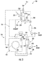
FIG. 2 illustrates another embodiment of a washing and drying apparatus is a variation of the washing and dryingapparatus 100. In this embodiment, a cooled water recirculation loop 162 and a heatedwater recirculation loop 164 are provided. When desired, thecontroller 150 may use thevalves thermoelectric apparatus 126 for additional cooling and heating. In some embodiments,temperature sensors controller 150 in determining whether or not to direct the water back through therecirculation loops 162 and 164. - While liquid-to-liquid thermoelectric apparatuses are discussed above, a liquid-to-air thermoelectric apparatus may be used. Referring to
FIG. 3 , another embodiment of a washing and dryingapparatus 180 includes many of the features discussed above, such as ahousing 182, atub 184, adrum 186, amotor 189, a closeddrying air circuit 188 and awash water circuit 190. As above, the closeddrying air circuit 188 includes anair circulation duct 192 that is fluidly connected to thedrum 186 during a drying cycle. Afan 196 may be provided to push air circulation through theair circulation duct 192 to and from thedrum 186. - Once the heated air is cycled through the
drum 186, the heated wet air is delivered through thecirculation duct 192 to anair inlet 200 of acondenser 202. Thecondenser 202 includes a condensingtube 204 that is fluidly connected to thecirculation duct 192 at both theair inlet 200 and anair outlet 206. As above, thecondenser 202 is configured to remove heat from the heated wet air and increase the relative humidity of the heated wet air before the air is reheated and delivered back to thedrum 186 with reduced relative humidity after heating back to about the same heated temperature. - A
thermoelectric apparatus 210 is provided between thecondenser 202 and atap water source 211. Thethermoelectric apparatus 210 includes a coldside flow device 212 that includes a coldside water input 214 and a coldside water output 216. Thethermoelectric apparatus 210 further includes a hot sideair flow device 218 that includes a plurality offins 220. Afan 222 may push air over thefins 220 to remove heat therefrom. The heated air may then be vented to the surroundings. Located between the coldside flow device 212 and the hot sideair flow device 218 is athermoelectric device 224. The washing and dryingapparatus 180 may further include a cooledwater storage 226, arecirculation loop 228 and acontroller 230 similar to those described above.FIG. 3 also shows a variation where heated air from thethermoelectric apparatus 210 is directed throughline 231 to the closeddrying air circuit 188. In some embodiments, there may not be a cooled water storage and cooled water may be sent directly to thecondenser 202. - While a single thermoelectric device is discussed above for the thermoelectric apparatuses, there may be multiple thermoelectric devices, such as in series or in parallel.
FIG. 4 shows an example of twothermoelectric devices thermoelectric device hot side cold side 242, 244. Thethermoelectric devices thermoelectric devices side flow device 248 and a hotside flow device 250 withtap water inlets outlets -
FIG. 5 shows an example of twothermoelectric devices thermoelectric device hot side cold side thermoelectric devices side flow device side flow device side flow devices tap water inlets outlets side flow devices tap water inlets outlets outlets outlets outlets - Clause 1: An apparatus comprising a closed drying air circuit, the apparatus comprising: a drum in communication with the closed drying air circuit; a condenser in communication with the closed drying air circuit and located downstream of the drum, the condenser comprising a cooled water inlet that directs cooled water into the heated air to remove moisture from the heated air, the condenser comprising a condenser water outlet for egress of water from the condenser, the cooled water inlet of the condenser configured to receive water from a tap water source; and a thermoelectric apparatus comprising a thermoelectric device, the thermoelectric apparatus comprising a cold side flow device arranged between the cooled water inlet of the condenser and the tap water source, the cold side flow device configured to receive tap water from the tap water source and cool the tap water below a tap outlet temperature using the thermoelectric device before the tap water enters the cooled water inlet of the condenser.
- Clause 2: The apparatus of clause 1, wherein a nozzle in the condenser is configured to spray the cooled water droplets into the heated air.
- Clause 3: The apparatus of clause 1 or 2, wherein a cold side of the thermoelectric device cools the tap water to no greater than about 9 °C.
- Clause 4: The apparatus of any one of clauses 1-3, wherein a cold side of the thermoelectric device cools the tap water to no greater than about 5 °C.
- Clause 5: The apparatus of any one of clauses 1-4, wherein the thermoelectric apparatus comprises a hot side flow device configured to receive tap water from the tap water source for transferring heat away from the cold side flow device.
- Clause 6: The apparatus of clause 5 further comprising a cooled water recirculation loop that directs at least some of the cooled water leaving the cold side flow device back to the cold side flow device to reintroduce the cooled water to the cold side flow device.
- Clause 7: The apparatus of clause 5 or 6, wherein the thermoelectric apparatus comprises multiple thermoelectric devices.
- Clause 8: The apparatus of any one of clauses 5-7 further comprising a wash water circuit in communication with the drum, the apparatus having a washing cycle where wash water is provided to the drum and a drying cycle where hot air is provided to the drum.
- Clause 9: The apparatus of clause 8 further comprising a heated water recirculation loop that directs at least some of the heated water leaving the hot side flow device back to the hot side flow device to reintroduce the heated water to the hot side flow device.
- Clause 10: The apparatus of clause 8 or 9, wherein heated water from the hot side flow device is directed to a drain during the drying cycle.
- Clause 11: The apparatus of any one of clauses 8-10 further comprising a memory and processing circuitry coupled to the memory, the memory including logic that, when executed by the processing circuitry, reduces a rate of flow of tap water to the hot side flow device and cold side flow device during the drying cycle using one or more valves.
- Clause 12: The apparatus of any one of clauses 8-11 further comprising a cooled water storage between the cold side flow device and the cooled water inlet of the condenser.
- Clause 13: The apparatus of
clause 12 further comprising a cooled water recirculation loop that delivers at least some of the cooled water from the cooled water storage to the cold side flow device. - Clause 14: The apparatus of clause 13 further comprising a heated water recirculation loop that delivers at least some of the heated water leaving the hot side flow device back to the hot side flow device to reintroduce the heated water to the hot side flow device.
- Clause 15: The apparatus of clause 13 further comprising a heated water storage between the hot side flow device and the drum.
- Clause 16: The apparatus of clause 15 further comprising a heated water recirculation loop that delivers at least some of the heated water from the heated water storage to the hot side flow device.
- Clause 17: The apparatus of
clause 15 or 16 further comprising a memory and processing circuitry coupled to the memory, the memory including logic that, when executed by the processing circuitry, directs cooled water from the cold side flow device to the cooled water storage during the washing cycle and directs heated water to the drum using one or more of a valve and a pump. - Clause 18: The apparatus of clause 17, wherein the memory including logic that, when executed by the processing circuitry, directs heated water from the hot side flow device to the heated water storage during the drying cycle and directs cooled water to the condenser using one or more of a valve and a pump.
- Clause 19: The apparatus of 18, wherein the heated water storage is a tub that surrounds the drum or is separate from the tub.
- Clause 20: The apparatus of clause 8 or 9 further comprising a heated water storage between the hot side flow device and the drum; and a cooled water recirculation loop that directs at least some of the cooled water leaving the cold side flow device back to the cold side flow device to reintroduce the cooled water to the cold side flow device.
- Clause 21: The apparatus of clause 1 further comprising a wash water circuit in communication with the drum, the apparatus having a washing cycle where wash water is provided to the drum and a drying cycle where hot air is provided to the drum; wherein the thermoelectric apparatus comprises a hot side flow device configured to receive air for transferring heat away from the cold side flow device.
- Clause 22: The apparatus of clause 21 further comprising a cooled water storage between the cold side flow device and the cooled water inlet of the condenser.
- Clause 23: The apparatus of
clause 22 further comprising a cooled water recirculation loop that delivers at least some of the cooled water from the cooled water storage to the cold side flow device. - Clause 24: The apparatus of any one of clauses 21-23, wherein heated air from the hot side flow device is vented outside the apparatus.
- Clause 25: The apparatus of any one of clauses 21-24, wherein heated air from the hot side flow device is delivered to the closed drying air circuit.
- Clause 26: An apparatus comprising a closed drying air circuit, the apparatus comprising: a drum in communication with the closed drying air circuit; a condenser in communication with the closed drying air circuit and located downstream of the drum, the condenser comprising a cooled water inlet that directs cooled water into the heated air to remove moisture from the heated air, the condenser comprising a condenser water outlet for egress of water from the condenser, the cooled water inlet of the condenser configured to receive water from a tap water source; and a thermoelectric apparatus comprising a thermoelectric device, the thermoelectric apparatus comprising a cold side flow device arranged between the cooled water inlet of the condenser and the tap water source, the cold side flow device configured to cool the tap water to no greater than about 9 °C using the thermoelectric device before the tap water enters the cooled water inlet of the condenser.
- Clause 27: The apparatus of
clause 26, wherein a cold side of the thermoelectric device cools the tap water to no greater than about 5 °C. - Clause 28: The apparatus of
clause - Clause 29: The apparatus of any one of clauses 26-28, wherein the thermoelectric device comprises a hot side flow device configured to receive tap water from the tap water source for transferring heat away from the cold side flow device.
- Clause 30: The apparatus of clause 29 further comprising a cooled water recirculation loop that directs at least some of the cooled water leaving the cold side flow device back to the cold side flow device to reintroduce the cooled water to the cold side flow device.
- Clause 31: The apparatus of
clause 29 or 30, wherein the thermoelectric apparatus comprises multiple thermoelectric devices. - Clause 32: The apparatus of any one of clauses 29-31 further comprising a wash water circuit in communication with the drum, the apparatus having a washing cycle where wash water is provided to the drum and a drying cycle where hot air is provided to the drum.
- Clause 33: The apparatus of
clause 32 further comprising a heated water recirculation loop that directs at least some of the heated water leaving the hot side flow device back to the hot side flow device to reintroduce the heated water to the hot side flow device. - Clause 34: The apparatus of
clause 32 or 33, wherein heated water from the hot side flow device is directed to a drain during the drying cycle. - Clause 35: The apparatus of any one of clauses 32-34 further comprising a memory and processing circuitry coupled to the memory, the memory including logic that, when executed by the processing circuitry, reduces a rate of flow of tap water to the hot side flow device and cold side flow device using one or more valves.
-
Clause 36. The apparatus of any one of clauses 32-35 further comprising a cooled water storage between the cold side flow device and the cooled water inlet of the condenser. - Clause 37: The apparatus of
clause 36 further comprising a cooled water recirculation loop that delivers at least some of the cooled water from the cooled water storage to the cold side flow device. - Clause 38: The apparatus of clause 37 further comprising a heated water recirculation loop that delivers at least some of the heated water leaving the hot side flow device back to the hot side flow device to reintroduce the heated water to the hot side flow device.
- Clause 39: The apparatus of
clause 36 further comprising a heated water storage between the hot side flow device and the drum. - Clause 40: The apparatus of clause 39 further comprising a heated water recirculation loop that delivers at least some of the heated water from the heated water storage to the hot side flow device.
- Clause 41: The apparatus of
clause 39 or 40 further comprising a memory and processing circuitry coupled to the memory, the memory including logic that, when executed by the processing circuitry, directs cooled water from the cold side flow device to the cooled water storage during the washing cycle and directs heated water to the drum using one or more of a valve and pump. - Clause 42: The apparatus of clause 41, wherein the memory including logic that, when executed by the processing circuitry, directs heated water from the hot side flow device to the heated water storage during the drying cycle and directs cooled water to the condenser using one or more of a valve and a pump.
- Clause 43: The apparatus of
claim 42, wherein the heated water storage is a tub that surrounds the drum or is separate from the tub. - Clause 44: The apparatus of
claim 32 further comprising a heated water storage between the hot side flow device and the drum; and a cooled water recirculation loop that directs at least some of the cooled water leaving the cold side flow device back to the cold side flow device to reintroduce the cooled water to the cold side flow device. - Clause 45: The apparatus of
claim 26 further comprising a wash water circuit in communication with the drum, the apparatus having a washing cycle where wash water is provided to the drum and a drying cycle where hot air is provided to the drum; wherein the thermoelectric device comprises a hot side flow device configured to receive air for transferring heat away from the cold side flow device. - Clause 46: The apparatus of clause 45 further comprising a cooled water storage between the cold side flow device and the cooled water inlet of the condenser.
- Clause 47: The apparatus of clause 45 or 46 further comprising a cooled water recirculation loop that delivers at least some of the cooled water from the cooled water storage to the cold side flow device.
- Clause 48: The apparatus of any one of clauses 45-47, wherein heated air from the hot side is vented outside the apparatus.
- Clause 49: The apparatus of any one of clauses 45-48, wherein heated air from the hot side is delivered to the closed drying air circuit.
- Clause 50: A method of removing water from heated air of an apparatus comprising a closed drying air circuit, the method comprising directing heated air from a drum to a condenser through the closed air drying circuit, the condenser comprising a cooled water inlet that provides cooled water to remove moisture from the heated air; directing tap water from a tap water source to a thermoelectric apparatus comprising a thermoelectric device, the thermoelectric apparatus comprising a cold side flow device arranged between the cooled water inlet of the condenser and the tap water source; and cooling the tap water below a tap outlet temperature using the thermoelectric device before the tap water enters the cooled water inlet of the condenser.
- Clause 51: The method of clause 50, wherein a nozzle in the condenser is configured to spray the cooled water into the heated air.
- Clause 52: The method of clause 50 or 51 comprising cooling the tap water to no greater than about 9 °C using the thermoelectric device.
- Clause 53: The method of clause 50 or 51 comprising cooling the tap water to no greater than about 5 °C using the thermoelectric device.
- Clause 54: The method of any one of clauses 50-53, wherein the thermoelectric apparatus comprises a hot side flow device configured to receive tap water from the tap water source for transferring heat away from the cold side flow device.
- Clause 55: The method of
clause 54 further comprising directing at least some of the cooled water leaving the cold side flow device back to the cold side flow device to reintroduce the cooled water to the cold side flow device using a cooled water recirculation loop. - Clause 56: The method of clause 55 further comprising a wash water circuit in communication with the drum, the apparatus having a washing cycle where wash water is provided to the drum and a drying cycle where hot air is provided to the drum.
- Clause 57: The method of
clause 56 further comprising directing at least some of the heated water leaving the hot side flow device back to the hot side to reintroduce the heated water to the hot side flow device using a heated water recirculation loop. - Clause 58: The method of
clause 56 or 57 further comprising directing heated water from the hot side flow device to a drain during the drying cycle. - Clause 59: The method of any one of clause 56-58 further comprising directing water leaving the condenser to a drain.
- Clause 60: The method of any one of clauses 56-59 further comprising a memory and processing circuitry coupled to the memory, the memory including logic that, when executed by the processing circuitry, reduces a rate of flow of tap water to the hot side during the drying cycle and reduces a rate of flow of tap water to the cold side during the washing cycle.
- Clause 61: The method of any one of clauses 56-60 further comprising a cooled water storage between the cold side flow device and the cooled water inlet of the condenser.
- Clause 62: The method of clause 61 further comprising delivering at least some of the cooled water from the cooled water storage to the cold side flow device using a cooled water recirculation loop.
- Clause 63: The method of
clause 62 further comprising delivering at least some of the heated water leaving the hot side flow device back to the hot side flow device to reintroduce the heated water to the hot side flow device using a heated water recirculation loop. - Clause 64: The method of
clause 62 or 63 further comprising a heated water storage between the hot side flow device and the drum. - Clause 65: The method of clause 64 further comprising delivering at least some of the heated water from the heated water storage to the hot side flow device using a heated water recirculation loop.
- Clause 66: The method of clause 64 or 65 further comprising a memory and processing circuitry coupled to the memory, the memory including logic that, when executed by the processing circuitry, directs cooled water from the cold side flow device to the cooled water storage during the washing cycle and directs heated water to the drum using one or more of a valve and a pump.
- Clause 67: The method of clause 66, wherein the memory including logic that, when executed by the processing circuitry, directs heated water from the hot side flow device to the heated water storage during the drying cycle and directs cooled water to the condenser using one or more of a valve and a pump.
- Clause 68: The method of clause 67, wherein the heated water storage is a tub that surrounds the drum or is separate from the tub.
- Clause 69: The method of
clause 56 further comprising a heated water storage between the hot side flow device and the drum; and a cooled water recirculation loop that directs at least some of the cooled water leaving the cold side flow device back to the cold side flow device to reintroduce the cooled water to the cold side flow device. - Clause 70: The method of claim 50 further comprising providing wash water to a drum using a wash water circuit, the apparatus having a washing cycle where wash water is provided to the drum and a drying cycle where hot air is provided to the drum; wherein the thermoelectric device comprises a hot side flow device configured to receive air for transferring heat away from the cold side.
- Clause 71: The method of
clause 70 further comprising a cooled water storage between the cold side flow device and the cooled water inlet of the condenser. - Clause 72: The method of clause 71 further comprising delivering at least some of the cooled water from the cooled water storage to the cold side flow device a cooled water recirculation loop.
- Clause 73: The method of any one of clauses 70-72 further comprising venting heated air from the hot side flow device outside the apparatus.
- Clause 74: The method of any one of claims 70-73 further comprising delivering heated air from the hot side flow device to the closed drying air circuit.
- The dimensions and values disclosed herein are not to be understood as being strictly limited to the exact numerical values recited. Instead, unless otherwise specified, each such dimension is intended to mean both the recited value and a functionally equivalent range surrounding that value. For example, a dimension disclosed as "40 mm" is intended to mean "about 40 mm."
Claims (15)
- An apparatus (10) comprising a closed drying air circuit (18), the apparatus comprising:a drum (16, 106, 186) in communication with the closed drying air circuit;a condenser (28, 118, 202) in communication with the closed drying air circuit and located downstream of the drum, the condenser comprising a cooled water inlet (60) that directs cooled water into heated air to remove moisture from the heated air, the condenser comprising a condenser water outlet (75) for egress of water from the condenser, the cooled water inlet of the condenser configured to receive water from a tap water source (38); anda thermoelectric apparatus (36, 126, 210) comprising a thermoelectric device (52, 142, 224), the thermoelectric apparatus comprising a cold side flow device (46, 136, 212) arranged between the cooled water inlet of the condenser and the tap water source, the cold side flow device configured to receive tap water from the tap water source and cool the tap water below a tap outlet temperature using the thermoelectric device before the tap water enters the cooled water inlet of the condenser.
- The apparatus according to claim 1, wherein a nozzle (64) in the condenser is configured to spray cooled water droplets into the heated air.
- The apparatus according to claim 1 or claim 2, wherein the thermoelectric apparatus comprises a hot side flow device (40, 130) configured to receive tap water from the tap water source for transferring heat away from the cold side flow device.
- The apparatus according to claim 3 further comprising a heated water recirculation loop (94, 164) that directs at least some of the heated water leaving the hot side flow device back to the hot side flow device to reintroduce the heated water to the hot side flow device.
- The apparatus according to any of claims 1 to 4 further comprising a cooled water recirculation loop (92, 162) that directs at least some of the cooled water leaving the cold side flow device back to the cold side flow device to reintroduce the cooled water to the cold side flow device.
- The apparatus according to any of claims 1 to 5 further comprising a wash water circuit (20, 110, 190) in communication with the drum, the apparatus having a washing cycle within which wash water is provided to the drum and a drying cycle within which hot air is provided to the drum.
- The apparatus according to any of claims 1 to 6 further comprising a cooled water storage (146, 226) between the cold side flow device and the cooled water inlet of the condenser.
- The apparatus of claim 7 further comprising a cooled water recirculation loop (92, 162) that delivers at least some of the cooled water from the cooled water storage to the cold side flow device.
- The apparatus according to any of claims 1 to 8, wherein the cold side flow device is configured to cool the tap water to no greater than about 9 °C using the thermoelectric device before the tap water enters the cooled water inlet of the condenser.
- A method of removing water from heated air of the apparatus according to any of claims 1 to 9, the method comprising:directing heated air from the drum to the condenser through the closed air drying circuit;directing tap water from the tap water source to the thermoelectric apparatus; andcooling the tap water below the tap outlet temperature using the thermoelectric device before the tap water enters the cooled water inlet of the condenser.
- The method according to claim 10 further comprising directing at least some of the cooled water leaving the cold side flow device back to the cold side flow device to reintroduce the cooled water to the cold side flow device using a cooled water recirculation loop.
- The method according to claim 10 or 11 further comprising a cooled water storage (144, 226) between the cold side flow device and the cooled water inlet of the condenser.
- The method according to claim 12 further comprising delivering at least some of the cooled water from the cooled water storage to the cold side flow device using a cooled water recirculation loop.
- The method according to claim 12 or claim 13 further comprising a memory and processing circuitry coupled to the memory, the memory including logic that, when executed by the processing circuitry, directs cooled water from the cold side flow device to the cooled water storage during a washing cycle and directs heated water to the drum using one or more of a valve and a pump.
- The method of claim 14, wherein the memory including logic that, when executed by the processing circuitry, directs heated water from a hot side flow device (40, 130) to a heated water storage (146) during a drying cycle and directs cooled water to the condenser using one or more of a valve (156) and a pump (166).
Priority Applications (6)
| Application Number | Priority Date | Filing Date | Title |
|---|---|---|---|
| EP19198046.5A EP3795738B1 (en) | 2019-09-18 | 2019-09-18 | Combination washing and drying apparatuses including cooled water condensers |
| PCT/US2020/070529 WO2021056015A1 (en) | 2019-09-18 | 2020-09-11 | Combination washing and drying apparatuses including cooled water condensers |
| CN202080059802.3A CN114364837B (en) | 2019-09-18 | 2020-09-11 | Combined washing and drying apparatus including cooling water condenser |
| JP2022512739A JP7339433B2 (en) | 2019-09-18 | 2020-09-11 | Apparatus with closed dry air circuit and method for removing water from the heated air of the apparatus |
| CA3149251A CA3149251A1 (en) | 2019-09-18 | 2020-09-11 | Combination washing and drying apparatuses including cooled water condensers |
| US17/024,915 US11952696B2 (en) | 2019-09-18 | 2020-09-18 | Combination washing and drying apparatuses including cooled water condensers |
Applications Claiming Priority (1)
| Application Number | Priority Date | Filing Date | Title |
|---|---|---|---|
| EP19198046.5A EP3795738B1 (en) | 2019-09-18 | 2019-09-18 | Combination washing and drying apparatuses including cooled water condensers |
Publications (2)
| Publication Number | Publication Date |
|---|---|
| EP3795738A1 true EP3795738A1 (en) | 2021-03-24 |
| EP3795738B1 EP3795738B1 (en) | 2022-08-17 |
Family
ID=67997487
Family Applications (1)
| Application Number | Title | Priority Date | Filing Date |
|---|---|---|---|
| EP19198046.5A Active EP3795738B1 (en) | 2019-09-18 | 2019-09-18 | Combination washing and drying apparatuses including cooled water condensers |
Country Status (6)
| Country | Link |
|---|---|
| US (1) | US11952696B2 (en) |
| EP (1) | EP3795738B1 (en) |
| JP (1) | JP7339433B2 (en) |
| CN (1) | CN114364837B (en) |
| CA (1) | CA3149251A1 (en) |
| WO (1) | WO2021056015A1 (en) |
Families Citing this family (2)
| Publication number | Priority date | Publication date | Assignee | Title |
|---|---|---|---|---|
| US11802364B2 (en) * | 2021-04-16 | 2023-10-31 | Whirlpool Corporation | Condensing system for combination washer/dryer appliance |
| TR2024003410A1 (en) * | 2024-03-20 | 2025-09-22 | Renta Elektrikli Ev Aletleri Sanayi Ve Dis Ticaret Ltd Sirketi | A COMBINED SYSTEM INCLUDING A CONDENSER DRYER |
Citations (3)
| Publication number | Priority date | Publication date | Assignee | Title |
|---|---|---|---|---|
| EP2372012A1 (en) * | 2010-03-30 | 2011-10-05 | DBK David + Baader GmbH | Household appliance, appropriate thermoelectric heat pump, appropriate condenser unit, and method for controlling such a household appliance |
| EP3192912A1 (en) * | 2016-01-14 | 2017-07-19 | BSH Hausgeräte GmbH | Washer-dryer with a cooling water circuit |
| EP3502344A1 (en) * | 2016-08-16 | 2019-06-26 | LG Electronics Inc. -1- | Clothes treatment apparatus |
Family Cites Families (23)
| Publication number | Priority date | Publication date | Assignee | Title |
|---|---|---|---|---|
| JP2678523B2 (en) * | 1990-10-16 | 1997-11-17 | シャープ株式会社 | Drum type washer / dryer |
| JPH1038431A (en) * | 1996-07-19 | 1998-02-13 | Shinko Electric Co Ltd | Water purifier |
| PT1211032E (en) | 1997-04-30 | 2004-08-31 | Black & Decker Inc | PROTECTION AND CONTROL EQUIPMENT FOR SLIDING HALF-SQUADRY COMBINATION SAW |
| JP4026469B2 (en) * | 2002-10-16 | 2007-12-26 | 松下電器産業株式会社 | Clothes dryer |
| KR101366561B1 (en) * | 2007-03-06 | 2014-02-25 | 삼성전자주식회사 | Washing machine and dry control method thereof |
| JP2008136848A (en) * | 2007-09-27 | 2008-06-19 | Sanyo Electric Co Ltd | Dryer |
| CN101480738B (en) | 2008-01-11 | 2013-09-11 | 力山工业股份有限公司 | Dust extraction devices for sawing machines |
| WO2011144539A1 (en) | 2010-05-20 | 2011-11-24 | Arcelik Anonim Sirketi | A washing machine wherein the unbalanced load is balanced |
| CN202062118U (en) | 2011-01-31 | 2011-12-07 | 南京德朔实业有限公司 | Beveling saw |
| KR101806836B1 (en) | 2011-05-04 | 2017-12-11 | 삼성전자주식회사 | Washing machine and control method thereof |
| US9834882B2 (en) * | 2011-07-07 | 2017-12-05 | Haier Us Appliance Solutions, Inc. | Device and method for heat pump based clothes dryer |
| JP2013188332A (en) | 2012-03-14 | 2013-09-26 | Hitachi Appliances Inc | Washing machine |
| JP2014113190A (en) * | 2012-12-06 | 2014-06-26 | Panasonic Corp | Washing and drying machine |
| EP2746455A1 (en) * | 2012-12-20 | 2014-06-25 | BSH Bosch und Siemens Hausgeräte GmbH | Process for operating a washer dryer with a heat pump, and a suitable washer dryer |
| CN103894676A (en) | 2012-12-28 | 2014-07-02 | 苏州宝时得电动工具有限公司 | Sawing machine and automatic dust absorption system applied to same |
| KR102091603B1 (en) | 2013-06-13 | 2020-03-20 | 엘지전자 주식회사 | Laundry Treating Apparatus |
| KR20150030832A (en) | 2013-09-12 | 2015-03-23 | 삼성전자주식회사 | Washing apparatus and controlling method thereof |
| JP2015160415A (en) | 2014-02-28 | 2015-09-07 | 日立工機株式会社 | Tabletop cutting machine |
| EP3153620B1 (en) | 2014-06-09 | 2020-02-05 | LG Electronics Inc. | Washing apparatus |
| KR101613962B1 (en) * | 2014-11-20 | 2016-04-20 | 엘지전자 주식회사 | Clothes treating apparatus with a heat pump system and control method for the same |
| EP3241944A1 (en) * | 2016-05-03 | 2017-11-08 | BSH Hausgeräte GmbH | Household appliance having a process air circuit |
| CN109423801B (en) | 2017-08-31 | 2022-04-22 | 青岛海尔洗衣机有限公司 | Washing machine |
| US11028527B2 (en) * | 2019-09-27 | 2021-06-08 | Whirlpool Corporation | Laundry treating appliance for drying laundry |
-
2019
- 2019-09-18 EP EP19198046.5A patent/EP3795738B1/en active Active
-
2020
- 2020-09-11 CN CN202080059802.3A patent/CN114364837B/en active Active
- 2020-09-11 JP JP2022512739A patent/JP7339433B2/en active Active
- 2020-09-11 WO PCT/US2020/070529 patent/WO2021056015A1/en not_active Ceased
- 2020-09-11 CA CA3149251A patent/CA3149251A1/en active Pending
- 2020-09-18 US US17/024,915 patent/US11952696B2/en active Active
Patent Citations (3)
| Publication number | Priority date | Publication date | Assignee | Title |
|---|---|---|---|---|
| EP2372012A1 (en) * | 2010-03-30 | 2011-10-05 | DBK David + Baader GmbH | Household appliance, appropriate thermoelectric heat pump, appropriate condenser unit, and method for controlling such a household appliance |
| EP3192912A1 (en) * | 2016-01-14 | 2017-07-19 | BSH Hausgeräte GmbH | Washer-dryer with a cooling water circuit |
| EP3502344A1 (en) * | 2016-08-16 | 2019-06-26 | LG Electronics Inc. -1- | Clothes treatment apparatus |
Also Published As
| Publication number | Publication date |
|---|---|
| EP3795738B1 (en) | 2022-08-17 |
| US20210079577A1 (en) | 2021-03-18 |
| JP7339433B2 (en) | 2023-09-05 |
| US11952696B2 (en) | 2024-04-09 |
| CN114364837B (en) | 2024-04-26 |
| WO2021056015A1 (en) | 2021-03-25 |
| CA3149251A1 (en) | 2021-03-25 |
| JP2022546359A (en) | 2022-11-04 |
| CN114364837A (en) | 2022-04-15 |
Similar Documents
| Publication | Publication Date | Title |
|---|---|---|
| EP3192913B1 (en) | Washer-dryer with a cooling water circuit | |
| EP2372012B1 (en) | Condenser unit, household appliance, and method for controlling such a household appliance | |
| WO2007108216A1 (en) | Cleaning device using water-based cleaning liquid | |
| US11952696B2 (en) | Combination washing and drying apparatuses including cooled water condensers | |
| CN110331566A (en) | Drying system and its application method | |
| CN109553270A (en) | A kind of pump type heat enclosed sludge drying system and its control method | |
| CN108006939A (en) | Drain pipe and dehumidifier | |
| KR20200094773A (en) | Control system and control method for HVAC unit, and medium containing such processor-executable instructions | |
| WO2019141010A1 (en) | Clothes drying apparatus and control method thereof | |
| EP2586905B1 (en) | A laundry dryer with a heat pump system | |
| KR100751060B1 (en) | Drying device using heat pump | |
| EP2594688B1 (en) | A laundry dryer with a heat pump system | |
| EP2540905B1 (en) | A laundry dryer with heat pump system | |
| EP3835476B1 (en) | Clothes drying system having control based on surrounding temperature detection | |
| WO2015131184A1 (en) | Freeze inhibiting regrigeration circuit and method of operation | |
| CN101688710B (en) | Method and system for rejecting heat in an absorption chiller | |
| LU101051B1 (en) | Compact and portable air conditioner | |
| KR101186562B1 (en) | Device having purging condensation water for car seat and the same method | |
| JP2012245496A (en) | Apparatus for dehumidifying compressed air | |
| US20140096562A1 (en) | Cooling system including a controlled atmospheric heat rejection cycle with water re-capture | |
| JP5921788B1 (en) | Cooling system | |
| CN111945401A (en) | Appliance for drying laundry and method for operating a heat pump of such an appliance | |
| CN119374279B (en) | Semiconductor is with binary channels refrigeration heating switching temperature control system | |
| JP6668724B2 (en) | Air cooler | |
| JP2010159925A (en) | Temperature control device |
Legal Events
| Date | Code | Title | Description |
|---|---|---|---|
| PUAI | Public reference made under article 153(3) epc to a published international application that has entered the european phase |
Free format text: ORIGINAL CODE: 0009012 |
|
| STAA | Information on the status of an ep patent application or granted ep patent |
Free format text: STATUS: THE APPLICATION HAS BEEN PUBLISHED |
|
| AK | Designated contracting states |
Kind code of ref document: A1 Designated state(s): AL AT BE BG CH CY CZ DE DK EE ES FI FR GB GR HR HU IE IS IT LI LT LU LV MC MK MT NL NO PL PT RO RS SE SI SK SM TR |
|
| AX | Request for extension of the european patent |
Extension state: BA ME |
|
| STAA | Information on the status of an ep patent application or granted ep patent |
Free format text: STATUS: REQUEST FOR EXAMINATION WAS MADE |
|
| 17P | Request for examination filed |
Effective date: 20210920 |
|
| RBV | Designated contracting states (corrected) |
Designated state(s): AL AT BE BG CH CY CZ DE DK EE ES FI FR GB GR HR HU IE IS IT LI LT LU LV MC MK MT NL NO PL PT RO RS SE SI SK SM TR |
|
| RIC1 | Information provided on ipc code assigned before grant |
Ipc: D06F 58/20 20060101ALN20220114BHEP Ipc: D06F 25/00 20060101ALN20220114BHEP Ipc: A47L 15/48 20060101ALN20220114BHEP Ipc: D06F 58/24 20060101AFI20220114BHEP |
|
| GRAP | Despatch of communication of intention to grant a patent |
Free format text: ORIGINAL CODE: EPIDOSNIGR1 |
|
| STAA | Information on the status of an ep patent application or granted ep patent |
Free format text: STATUS: GRANT OF PATENT IS INTENDED |
|
| RIC1 | Information provided on ipc code assigned before grant |
Ipc: D06F 58/20 20060101ALN20220204BHEP Ipc: D06F 25/00 20060101ALN20220204BHEP Ipc: A47L 15/48 20060101ALN20220204BHEP Ipc: D06F 58/24 20060101AFI20220204BHEP |
|
| INTG | Intention to grant announced |
Effective date: 20220315 |
|
| GRAS | Grant fee paid |
Free format text: ORIGINAL CODE: EPIDOSNIGR3 |
|
| GRAA | (expected) grant |
Free format text: ORIGINAL CODE: 0009210 |
|
| STAA | Information on the status of an ep patent application or granted ep patent |
Free format text: STATUS: THE PATENT HAS BEEN GRANTED |
|
| AK | Designated contracting states |
Kind code of ref document: B1 Designated state(s): AL AT BE BG CH CY CZ DE DK EE ES FI FR GB GR HR HU IE IS IT LI LT LU LV MC MK MT NL NO PL PT RO RS SE SI SK SM TR |
|
| REG | Reference to a national code |
Ref country code: CH Ref legal event code: EP |
|
| REG | Reference to a national code |
Ref country code: DE Ref legal event code: R096 Ref document number: 602019018307 Country of ref document: DE |
|
| REG | Reference to a national code |
Ref country code: IE Ref legal event code: FG4D |
|
| REG | Reference to a national code |
Ref country code: AT Ref legal event code: REF Ref document number: 1512238 Country of ref document: AT Kind code of ref document: T Effective date: 20220915 |
|
| REG | Reference to a national code |
Ref country code: NL Ref legal event code: MP Effective date: 20220817 |
|
| REG | Reference to a national code |
Ref country code: LT Ref legal event code: MG9D |
|
| PG25 | Lapsed in a contracting state [announced via postgrant information from national office to epo] |
Ref country code: SE Free format text: LAPSE BECAUSE OF FAILURE TO SUBMIT A TRANSLATION OF THE DESCRIPTION OR TO PAY THE FEE WITHIN THE PRESCRIBED TIME-LIMIT Effective date: 20220817 Ref country code: RS Free format text: LAPSE BECAUSE OF FAILURE TO SUBMIT A TRANSLATION OF THE DESCRIPTION OR TO PAY THE FEE WITHIN THE PRESCRIBED TIME-LIMIT Effective date: 20220817 Ref country code: PT Free format text: LAPSE BECAUSE OF FAILURE TO SUBMIT A TRANSLATION OF THE DESCRIPTION OR TO PAY THE FEE WITHIN THE PRESCRIBED TIME-LIMIT Effective date: 20221219 Ref country code: NO Free format text: LAPSE BECAUSE OF FAILURE TO SUBMIT A TRANSLATION OF THE DESCRIPTION OR TO PAY THE FEE WITHIN THE PRESCRIBED TIME-LIMIT Effective date: 20221117 Ref country code: NL Free format text: LAPSE BECAUSE OF FAILURE TO SUBMIT A TRANSLATION OF THE DESCRIPTION OR TO PAY THE FEE WITHIN THE PRESCRIBED TIME-LIMIT Effective date: 20220817 Ref country code: LV Free format text: LAPSE BECAUSE OF FAILURE TO SUBMIT A TRANSLATION OF THE DESCRIPTION OR TO PAY THE FEE WITHIN THE PRESCRIBED TIME-LIMIT Effective date: 20220817 Ref country code: LT Free format text: LAPSE BECAUSE OF FAILURE TO SUBMIT A TRANSLATION OF THE DESCRIPTION OR TO PAY THE FEE WITHIN THE PRESCRIBED TIME-LIMIT Effective date: 20220817 Ref country code: FI Free format text: LAPSE BECAUSE OF FAILURE TO SUBMIT A TRANSLATION OF THE DESCRIPTION OR TO PAY THE FEE WITHIN THE PRESCRIBED TIME-LIMIT Effective date: 20220817 |
|
| REG | Reference to a national code |
Ref country code: AT Ref legal event code: MK05 Ref document number: 1512238 Country of ref document: AT Kind code of ref document: T Effective date: 20220817 |
|
| PG25 | Lapsed in a contracting state [announced via postgrant information from national office to epo] |
Ref country code: PL Free format text: LAPSE BECAUSE OF FAILURE TO SUBMIT A TRANSLATION OF THE DESCRIPTION OR TO PAY THE FEE WITHIN THE PRESCRIBED TIME-LIMIT Effective date: 20220817 Ref country code: IS Free format text: LAPSE BECAUSE OF FAILURE TO SUBMIT A TRANSLATION OF THE DESCRIPTION OR TO PAY THE FEE WITHIN THE PRESCRIBED TIME-LIMIT Effective date: 20221217 Ref country code: HR Free format text: LAPSE BECAUSE OF FAILURE TO SUBMIT A TRANSLATION OF THE DESCRIPTION OR TO PAY THE FEE WITHIN THE PRESCRIBED TIME-LIMIT Effective date: 20220817 Ref country code: GR Free format text: LAPSE BECAUSE OF FAILURE TO SUBMIT A TRANSLATION OF THE DESCRIPTION OR TO PAY THE FEE WITHIN THE PRESCRIBED TIME-LIMIT Effective date: 20221118 |
|
| PG25 | Lapsed in a contracting state [announced via postgrant information from national office to epo] |
Ref country code: SM Free format text: LAPSE BECAUSE OF FAILURE TO SUBMIT A TRANSLATION OF THE DESCRIPTION OR TO PAY THE FEE WITHIN THE PRESCRIBED TIME-LIMIT Effective date: 20220817 Ref country code: RO Free format text: LAPSE BECAUSE OF FAILURE TO SUBMIT A TRANSLATION OF THE DESCRIPTION OR TO PAY THE FEE WITHIN THE PRESCRIBED TIME-LIMIT Effective date: 20220817 Ref country code: ES Free format text: LAPSE BECAUSE OF FAILURE TO SUBMIT A TRANSLATION OF THE DESCRIPTION OR TO PAY THE FEE WITHIN THE PRESCRIBED TIME-LIMIT Effective date: 20220817 Ref country code: DK Free format text: LAPSE BECAUSE OF FAILURE TO SUBMIT A TRANSLATION OF THE DESCRIPTION OR TO PAY THE FEE WITHIN THE PRESCRIBED TIME-LIMIT Effective date: 20220817 Ref country code: CZ Free format text: LAPSE BECAUSE OF FAILURE TO SUBMIT A TRANSLATION OF THE DESCRIPTION OR TO PAY THE FEE WITHIN THE PRESCRIBED TIME-LIMIT Effective date: 20220817 Ref country code: AT Free format text: LAPSE BECAUSE OF FAILURE TO SUBMIT A TRANSLATION OF THE DESCRIPTION OR TO PAY THE FEE WITHIN THE PRESCRIBED TIME-LIMIT Effective date: 20220817 |
|
| REG | Reference to a national code |
Ref country code: CH Ref legal event code: PL |
|
| REG | Reference to a national code |
Ref country code: DE Ref legal event code: R097 Ref document number: 602019018307 Country of ref document: DE |
|
| REG | Reference to a national code |
Ref country code: BE Ref legal event code: MM Effective date: 20220930 |
|
| PG25 | Lapsed in a contracting state [announced via postgrant information from national office to epo] |
Ref country code: SK Free format text: LAPSE BECAUSE OF FAILURE TO SUBMIT A TRANSLATION OF THE DESCRIPTION OR TO PAY THE FEE WITHIN THE PRESCRIBED TIME-LIMIT Effective date: 20220817 Ref country code: MC Free format text: LAPSE BECAUSE OF FAILURE TO SUBMIT A TRANSLATION OF THE DESCRIPTION OR TO PAY THE FEE WITHIN THE PRESCRIBED TIME-LIMIT Effective date: 20220817 Ref country code: EE Free format text: LAPSE BECAUSE OF FAILURE TO SUBMIT A TRANSLATION OF THE DESCRIPTION OR TO PAY THE FEE WITHIN THE PRESCRIBED TIME-LIMIT Effective date: 20220817 |
|
| P01 | Opt-out of the competence of the unified patent court (upc) registered |
Effective date: 20230429 |
|
| PLBE | No opposition filed within time limit |
Free format text: ORIGINAL CODE: 0009261 |
|
| STAA | Information on the status of an ep patent application or granted ep patent |
Free format text: STATUS: NO OPPOSITION FILED WITHIN TIME LIMIT |
|
| PG25 | Lapsed in a contracting state [announced via postgrant information from national office to epo] |
Ref country code: LU Free format text: LAPSE BECAUSE OF NON-PAYMENT OF DUE FEES Effective date: 20220918 Ref country code: AL Free format text: LAPSE BECAUSE OF FAILURE TO SUBMIT A TRANSLATION OF THE DESCRIPTION OR TO PAY THE FEE WITHIN THE PRESCRIBED TIME-LIMIT Effective date: 20220817 |
|
| 26N | No opposition filed |
Effective date: 20230519 |
|
| PG25 | Lapsed in a contracting state [announced via postgrant information from national office to epo] |
Ref country code: LI Free format text: LAPSE BECAUSE OF NON-PAYMENT OF DUE FEES Effective date: 20220930 Ref country code: IE Free format text: LAPSE BECAUSE OF NON-PAYMENT OF DUE FEES Effective date: 20220918 Ref country code: CH Free format text: LAPSE BECAUSE OF NON-PAYMENT OF DUE FEES Effective date: 20220930 |
|
| PG25 | Lapsed in a contracting state [announced via postgrant information from national office to epo] |
Ref country code: SI Free format text: LAPSE BECAUSE OF FAILURE TO SUBMIT A TRANSLATION OF THE DESCRIPTION OR TO PAY THE FEE WITHIN THE PRESCRIBED TIME-LIMIT Effective date: 20220817 |
|
| PG25 | Lapsed in a contracting state [announced via postgrant information from national office to epo] |
Ref country code: BE Free format text: LAPSE BECAUSE OF NON-PAYMENT OF DUE FEES Effective date: 20220930 |
|
| PG25 | Lapsed in a contracting state [announced via postgrant information from national office to epo] |
Ref country code: CY Free format text: LAPSE BECAUSE OF FAILURE TO SUBMIT A TRANSLATION OF THE DESCRIPTION OR TO PAY THE FEE WITHIN THE PRESCRIBED TIME-LIMIT Effective date: 20220817 |
|
| PG25 | Lapsed in a contracting state [announced via postgrant information from national office to epo] |
Ref country code: MK Free format text: LAPSE BECAUSE OF FAILURE TO SUBMIT A TRANSLATION OF THE DESCRIPTION OR TO PAY THE FEE WITHIN THE PRESCRIBED TIME-LIMIT Effective date: 20220817 Ref country code: IT Free format text: LAPSE BECAUSE OF FAILURE TO SUBMIT A TRANSLATION OF THE DESCRIPTION OR TO PAY THE FEE WITHIN THE PRESCRIBED TIME-LIMIT Effective date: 20220817 Ref country code: HU Free format text: LAPSE BECAUSE OF FAILURE TO SUBMIT A TRANSLATION OF THE DESCRIPTION OR TO PAY THE FEE WITHIN THE PRESCRIBED TIME-LIMIT; INVALID AB INITIO Effective date: 20190918 |
|
| PG25 | Lapsed in a contracting state [announced via postgrant information from national office to epo] |
Ref country code: BG Free format text: LAPSE BECAUSE OF FAILURE TO SUBMIT A TRANSLATION OF THE DESCRIPTION OR TO PAY THE FEE WITHIN THE PRESCRIBED TIME-LIMIT Effective date: 20220817 |
|
| PG25 | Lapsed in a contracting state [announced via postgrant information from national office to epo] |
Ref country code: MT Free format text: LAPSE BECAUSE OF FAILURE TO SUBMIT A TRANSLATION OF THE DESCRIPTION OR TO PAY THE FEE WITHIN THE PRESCRIBED TIME-LIMIT Effective date: 20220817 |
|
| PGFP | Annual fee paid to national office [announced via postgrant information from national office to epo] |
Ref country code: DE Payment date: 20250730 Year of fee payment: 7 |
|
| PGFP | Annual fee paid to national office [announced via postgrant information from national office to epo] |
Ref country code: GB Payment date: 20250731 Year of fee payment: 7 |
|
| PGFP | Annual fee paid to national office [announced via postgrant information from national office to epo] |
Ref country code: FR Payment date: 20250808 Year of fee payment: 7 |
|
| PG25 | Lapsed in a contracting state [announced via postgrant information from national office to epo] |
Ref country code: TR Free format text: LAPSE BECAUSE OF FAILURE TO SUBMIT A TRANSLATION OF THE DESCRIPTION OR TO PAY THE FEE WITHIN THE PRESCRIBED TIME-LIMIT Effective date: 20220817 |