EP3795719A1 - Electrochemical reaction device - Google Patents
Electrochemical reaction device Download PDFInfo
- Publication number
- EP3795719A1 EP3795719A1 EP20160393.3A EP20160393A EP3795719A1 EP 3795719 A1 EP3795719 A1 EP 3795719A1 EP 20160393 A EP20160393 A EP 20160393A EP 3795719 A1 EP3795719 A1 EP 3795719A1
- Authority
- EP
- European Patent Office
- Prior art keywords
- room
- carbon dioxide
- temperature
- reactor
- electrolytic solution
- Prior art date
- Legal status (The legal status is an assumption and is not a legal conclusion. Google has not performed a legal analysis and makes no representation as to the accuracy of the status listed.)
- Pending
Links
Images

Classifications
-
- C—CHEMISTRY; METALLURGY
- C25—ELECTROLYTIC OR ELECTROPHORETIC PROCESSES; APPARATUS THEREFOR
- C25B—ELECTROLYTIC OR ELECTROPHORETIC PROCESSES FOR THE PRODUCTION OF COMPOUNDS OR NON-METALS; APPARATUS THEREFOR
- C25B15/00—Operating or servicing cells
- C25B15/02—Process control or regulation
-
- C—CHEMISTRY; METALLURGY
- C25—ELECTROLYTIC OR ELECTROPHORETIC PROCESSES; APPARATUS THEREFOR
- C25B—ELECTROLYTIC OR ELECTROPHORETIC PROCESSES FOR THE PRODUCTION OF COMPOUNDS OR NON-METALS; APPARATUS THEREFOR
- C25B13/00—Diaphragms; Spacing elements
- C25B13/04—Diaphragms; Spacing elements characterised by the material
- C25B13/08—Diaphragms; Spacing elements characterised by the material based on organic materials
-
- C—CHEMISTRY; METALLURGY
- C25—ELECTROLYTIC OR ELECTROPHORETIC PROCESSES; APPARATUS THEREFOR
- C25B—ELECTROLYTIC OR ELECTROPHORETIC PROCESSES FOR THE PRODUCTION OF COMPOUNDS OR NON-METALS; APPARATUS THEREFOR
- C25B1/00—Electrolytic production of inorganic compounds or non-metals
-
- C—CHEMISTRY; METALLURGY
- C25—ELECTROLYTIC OR ELECTROPHORETIC PROCESSES; APPARATUS THEREFOR
- C25B—ELECTROLYTIC OR ELECTROPHORETIC PROCESSES FOR THE PRODUCTION OF COMPOUNDS OR NON-METALS; APPARATUS THEREFOR
- C25B1/00—Electrolytic production of inorganic compounds or non-metals
- C25B1/01—Products
- C25B1/02—Hydrogen or oxygen
- C25B1/04—Hydrogen or oxygen by electrolysis of water
-
- C—CHEMISTRY; METALLURGY
- C25—ELECTROLYTIC OR ELECTROPHORETIC PROCESSES; APPARATUS THEREFOR
- C25B—ELECTROLYTIC OR ELECTROPHORETIC PROCESSES FOR THE PRODUCTION OF COMPOUNDS OR NON-METALS; APPARATUS THEREFOR
- C25B1/00—Electrolytic production of inorganic compounds or non-metals
- C25B1/01—Products
- C25B1/23—Carbon monoxide or syngas
-
- C—CHEMISTRY; METALLURGY
- C25—ELECTROLYTIC OR ELECTROPHORETIC PROCESSES; APPARATUS THEREFOR
- C25B—ELECTROLYTIC OR ELECTROPHORETIC PROCESSES FOR THE PRODUCTION OF COMPOUNDS OR NON-METALS; APPARATUS THEREFOR
- C25B11/00—Electrodes; Manufacture thereof not otherwise provided for
- C25B11/02—Electrodes; Manufacture thereof not otherwise provided for characterised by shape or form
- C25B11/03—Electrodes; Manufacture thereof not otherwise provided for characterised by shape or form perforated or foraminous
- C25B11/031—Porous electrodes
-
- C—CHEMISTRY; METALLURGY
- C25—ELECTROLYTIC OR ELECTROPHORETIC PROCESSES; APPARATUS THEREFOR
- C25B—ELECTROLYTIC OR ELECTROPHORETIC PROCESSES FOR THE PRODUCTION OF COMPOUNDS OR NON-METALS; APPARATUS THEREFOR
- C25B11/00—Electrodes; Manufacture thereof not otherwise provided for
- C25B11/04—Electrodes; Manufacture thereof not otherwise provided for characterised by the material
- C25B11/051—Electrodes formed of electrocatalysts on a substrate or carrier
- C25B11/055—Electrodes formed of electrocatalysts on a substrate or carrier characterised by the substrate or carrier material
- C25B11/057—Electrodes formed of electrocatalysts on a substrate or carrier characterised by the substrate or carrier material consisting of a single element or compound
- C25B11/061—Metal or alloy
- C25B11/063—Valve metal, e.g. titanium
-
- C—CHEMISTRY; METALLURGY
- C25—ELECTROLYTIC OR ELECTROPHORETIC PROCESSES; APPARATUS THEREFOR
- C25B—ELECTROLYTIC OR ELECTROPHORETIC PROCESSES FOR THE PRODUCTION OF COMPOUNDS OR NON-METALS; APPARATUS THEREFOR
- C25B11/00—Electrodes; Manufacture thereof not otherwise provided for
- C25B11/04—Electrodes; Manufacture thereof not otherwise provided for characterised by the material
- C25B11/051—Electrodes formed of electrocatalysts on a substrate or carrier
- C25B11/055—Electrodes formed of electrocatalysts on a substrate or carrier characterised by the substrate or carrier material
- C25B11/057—Electrodes formed of electrocatalysts on a substrate or carrier characterised by the substrate or carrier material consisting of a single element or compound
- C25B11/065—Carbon
-
- C—CHEMISTRY; METALLURGY
- C25—ELECTROLYTIC OR ELECTROPHORETIC PROCESSES; APPARATUS THEREFOR
- C25B—ELECTROLYTIC OR ELECTROPHORETIC PROCESSES FOR THE PRODUCTION OF COMPOUNDS OR NON-METALS; APPARATUS THEREFOR
- C25B11/00—Electrodes; Manufacture thereof not otherwise provided for
- C25B11/04—Electrodes; Manufacture thereof not otherwise provided for characterised by the material
- C25B11/051—Electrodes formed of electrocatalysts on a substrate or carrier
- C25B11/073—Electrodes formed of electrocatalysts on a substrate or carrier characterised by the electrocatalyst material
- C25B11/075—Electrodes formed of electrocatalysts on a substrate or carrier characterised by the electrocatalyst material consisting of a single catalytic element or catalytic compound
- C25B11/081—Electrodes formed of electrocatalysts on a substrate or carrier characterised by the electrocatalyst material consisting of a single catalytic element or catalytic compound the element being a noble metal
-
- C—CHEMISTRY; METALLURGY
- C25—ELECTROLYTIC OR ELECTROPHORETIC PROCESSES; APPARATUS THEREFOR
- C25B—ELECTROLYTIC OR ELECTROPHORETIC PROCESSES FOR THE PRODUCTION OF COMPOUNDS OR NON-METALS; APPARATUS THEREFOR
- C25B13/00—Diaphragms; Spacing elements
- C25B13/02—Diaphragms; Spacing elements characterised by shape or form
-
- C—CHEMISTRY; METALLURGY
- C25—ELECTROLYTIC OR ELECTROPHORETIC PROCESSES; APPARATUS THEREFOR
- C25B—ELECTROLYTIC OR ELECTROPHORETIC PROCESSES FOR THE PRODUCTION OF COMPOUNDS OR NON-METALS; APPARATUS THEREFOR
- C25B15/00—Operating or servicing cells
- C25B15/02—Process control or regulation
- C25B15/023—Measuring, analysing or testing during electrolytic production
-
- C—CHEMISTRY; METALLURGY
- C25—ELECTROLYTIC OR ELECTROPHORETIC PROCESSES; APPARATUS THEREFOR
- C25B—ELECTROLYTIC OR ELECTROPHORETIC PROCESSES FOR THE PRODUCTION OF COMPOUNDS OR NON-METALS; APPARATUS THEREFOR
- C25B15/00—Operating or servicing cells
- C25B15/02—Process control or regulation
- C25B15/023—Measuring, analysing or testing during electrolytic production
- C25B15/025—Measuring, analysing or testing during electrolytic production of electrolyte parameters
- C25B15/027—Temperature
-
- C—CHEMISTRY; METALLURGY
- C25—ELECTROLYTIC OR ELECTROPHORETIC PROCESSES; APPARATUS THEREFOR
- C25B—ELECTROLYTIC OR ELECTROPHORETIC PROCESSES FOR THE PRODUCTION OF COMPOUNDS OR NON-METALS; APPARATUS THEREFOR
- C25B3/00—Electrolytic production of organic compounds
- C25B3/01—Products
- C25B3/03—Acyclic or carbocyclic hydrocarbons
-
- C—CHEMISTRY; METALLURGY
- C25—ELECTROLYTIC OR ELECTROPHORETIC PROCESSES; APPARATUS THEREFOR
- C25B—ELECTROLYTIC OR ELECTROPHORETIC PROCESSES FOR THE PRODUCTION OF COMPOUNDS OR NON-METALS; APPARATUS THEREFOR
- C25B3/00—Electrolytic production of organic compounds
- C25B3/01—Products
- C25B3/07—Oxygen containing compounds
-
- C—CHEMISTRY; METALLURGY
- C25—ELECTROLYTIC OR ELECTROPHORETIC PROCESSES; APPARATUS THEREFOR
- C25B—ELECTROLYTIC OR ELECTROPHORETIC PROCESSES FOR THE PRODUCTION OF COMPOUNDS OR NON-METALS; APPARATUS THEREFOR
- C25B3/00—Electrolytic production of organic compounds
- C25B3/20—Processes
- C25B3/25—Reduction
-
- C—CHEMISTRY; METALLURGY
- C25—ELECTROLYTIC OR ELECTROPHORETIC PROCESSES; APPARATUS THEREFOR
- C25B—ELECTROLYTIC OR ELECTROPHORETIC PROCESSES FOR THE PRODUCTION OF COMPOUNDS OR NON-METALS; APPARATUS THEREFOR
- C25B3/00—Electrolytic production of organic compounds
- C25B3/20—Processes
- C25B3/25—Reduction
- C25B3/26—Reduction of carbon dioxide
-
- C—CHEMISTRY; METALLURGY
- C25—ELECTROLYTIC OR ELECTROPHORETIC PROCESSES; APPARATUS THEREFOR
- C25B—ELECTROLYTIC OR ELECTROPHORETIC PROCESSES FOR THE PRODUCTION OF COMPOUNDS OR NON-METALS; APPARATUS THEREFOR
- C25B9/00—Cells or assemblies of cells; Constructional parts of cells; Assemblies of constructional parts, e.g. electrode-diaphragm assemblies; Process-related cell features
- C25B9/17—Cells comprising dimensionally-stable non-movable electrodes; Assemblies of constructional parts thereof
- C25B9/19—Cells comprising dimensionally-stable non-movable electrodes; Assemblies of constructional parts thereof with diaphragms
-
- C—CHEMISTRY; METALLURGY
- C25—ELECTROLYTIC OR ELECTROPHORETIC PROCESSES; APPARATUS THEREFOR
- C25B—ELECTROLYTIC OR ELECTROPHORETIC PROCESSES FOR THE PRODUCTION OF COMPOUNDS OR NON-METALS; APPARATUS THEREFOR
- C25B9/00—Cells or assemblies of cells; Constructional parts of cells; Assemblies of constructional parts, e.g. electrode-diaphragm assemblies; Process-related cell features
- C25B9/70—Assemblies comprising two or more cells
- C25B9/73—Assemblies comprising two or more cells of the filter-press type
-
- C—CHEMISTRY; METALLURGY
- C25—ELECTROLYTIC OR ELECTROPHORETIC PROCESSES; APPARATUS THEREFOR
- C25B—ELECTROLYTIC OR ELECTROPHORETIC PROCESSES FOR THE PRODUCTION OF COMPOUNDS OR NON-METALS; APPARATUS THEREFOR
- C25B9/00—Cells or assemblies of cells; Constructional parts of cells; Assemblies of constructional parts, e.g. electrode-diaphragm assemblies; Process-related cell features
- C25B9/70—Assemblies comprising two or more cells
- C25B9/73—Assemblies comprising two or more cells of the filter-press type
- C25B9/77—Assemblies comprising two or more cells of the filter-press type having diaphragms
-
- Y—GENERAL TAGGING OF NEW TECHNOLOGICAL DEVELOPMENTS; GENERAL TAGGING OF CROSS-SECTIONAL TECHNOLOGIES SPANNING OVER SEVERAL SECTIONS OF THE IPC; TECHNICAL SUBJECTS COVERED BY FORMER USPC CROSS-REFERENCE ART COLLECTIONS [XRACs] AND DIGESTS
- Y02—TECHNOLOGIES OR APPLICATIONS FOR MITIGATION OR ADAPTATION AGAINST CLIMATE CHANGE
- Y02E—REDUCTION OF GREENHOUSE GAS [GHG] EMISSIONS, RELATED TO ENERGY GENERATION, TRANSMISSION OR DISTRIBUTION
- Y02E60/00—Enabling technologies; Technologies with a potential or indirect contribution to GHG emissions mitigation
- Y02E60/30—Hydrogen technology
- Y02E60/36—Hydrogen production from non-carbon containing sources, e.g. by water electrolysis
-
- Y—GENERAL TAGGING OF NEW TECHNOLOGICAL DEVELOPMENTS; GENERAL TAGGING OF CROSS-SECTIONAL TECHNOLOGIES SPANNING OVER SEVERAL SECTIONS OF THE IPC; TECHNICAL SUBJECTS COVERED BY FORMER USPC CROSS-REFERENCE ART COLLECTIONS [XRACs] AND DIGESTS
- Y02—TECHNOLOGIES OR APPLICATIONS FOR MITIGATION OR ADAPTATION AGAINST CLIMATE CHANGE
- Y02P—CLIMATE CHANGE MITIGATION TECHNOLOGIES IN THE PRODUCTION OR PROCESSING OF GOODS
- Y02P20/00—Technologies relating to chemical industry
- Y02P20/10—Process efficiency
- Y02P20/133—Renewable energy sources, e.g. sunlight
Definitions
- Arrangements described herein relate generally to an electrochemical reaction device.
- An electrochemical reaction device enabling the artificial photosynthesis technology includes, for example, an anode that oxidizes water (H 2 O) to produce oxygen (O 2 ), and a cathode that reduces carbon dioxide (CO 2 ) to produce a carbon compound.
- the anode and the cathode of the electrochemical reaction device are generally connected to a power supply derived from renewable energy such as solar power generation, hydroelectric power generation, wind power generation, geothermal power generation or the like.
- the cathode of the electrochemical reaction device is disposed, for example, to be immersed in water in which carbon dioxide is dissolved or to be in contact with water which flows through a flow path and in which carbon dioxide is dissolved.
- the cathode obtains reduction potential for carbon dioxide from the power supply derived from renewable energy and thereby reduces carbon dioxide to produce carbon compounds such as carbon monoxide (CO), formic acid (HCOOH), methanol (CH 3 OH), methane (CH 4 ), ethanol (C 2 H 5 OH), ethane (C 2 H 6 ), ethylene (C 2 H 4 ), and ethylene glycol (C 2 H 6 O 2 ).
- the electrochemical reaction device is experimentally operated by using a power supply such as a potentiostat capable of applying a constant potential to the cathode (three-electrode system), but this loses advantages owing to the utilization of the renewable energy and results in a problem in terms of cost and efficiency.
- a power supply such as a potentiostat capable of applying a constant potential to the cathode (three-electrode system)
- a problem to be solved by the present invention is to provide an electrochemical reaction device capable of suppressing successive fluctuations in a production amount and a composition of a reduction product of carbon dioxide due to increase and fluctuation in temperature in a reaction unit caused by Joule heat when a large amount of carbon dioxide is reduced.
- An electrochemical reaction device includes: a first reactor including a first room and a second room, the first room being configured to store a gas containing carbon dioxide or a first electrolytic solution containing carbon dioxide, and the second room being configured to store a second electrolytic solution containing water; a cathode disposed in the first room, the cathode being configured to reduce the carbon dioxide and thus produce a reduction product; an anode disposed in the second room, the anode being configured to oxidize the water and thus produce an oxidation product; a first pressure adjuster configured to adjust pressure in the first room; a temperature detector configured to detect a temperature in the first reactor to form a detection signal; and a controller configured to control the pressure adjuster in accordance with the detection signal from the temperature detector.
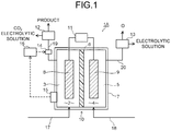
- Fig. 1 is a diagram illustrating an electrochemical reaction device 1A.
- the electrochemical reaction device 1A includes: an electrochemical reaction cell 10 including a first reactor 7 including a first room 3 configured to store a first electrolytic solution 2 containing carbon dioxide, a second room 5 configured to store a second electrolytic solution 4 containing water, and a diaphragm 6 configured to divide between the first room 3 and the second room 5, a cathode 8 disposed in the first room 3 and configured to produce a reduction product by reducing carbon dioxide, and an anode 9 disposed in the second room 5 and configured to produce an oxidation product by oxidizing water; a power supply 11 connected to the cathode 8 and the anode 9; a first separation unit 12 configured to separate the reduction product produced at the first room 3 from the first electrolytic solution 2; a second separation unit 13 configured to separate the oxidation product produced at the second room 5 from the second electrolytic solution 4; a pressure adjuster 14 configured to adjust pressure in the first room 3; a temperature detector 15
- the first reactor 7 has the first room 3 and the second room 5 divided by the diaphragm 6 capable of moving ions such as hydrogen ions (H + ) and hydroxide ions (OH - ).
- the first reactor 7 may be made of a container of, for example, quartz white plate glass, polystyrol, polymethacrylate or the like. A material transmitting light may be used for a part of the first reactor 7, and a resin material may be used for the remainder.
- the resin material examples include, for example, polyetheretherketone (PEEK), polyamide (PA), polyvinylidene fluoride (PVDF), polyacetal (POM) (copolymer), polyphenyleneether (PPE), acrylonitrile-butadiene-styrene copolymer (ABS), polypropylene (PP), polyethylene (PE) and so on.
- PEEK polyetheretherketone
- PA polyamide
- PVDF polyvinylidene fluoride
- POM polyacetal
- PPE polyphenyleneether
- ABS acrylonitrile-butadiene-styrene copolymer
- PP polypropylene
- PE polyethylene
- the cathode 8 is disposed in the first room 3, and the first electrolytic solution 2 is stored such that the cathode 8 is in contact with the first electrolytic solution 2.
- the first electrolytic solution 2 functions as a cathode solution and contains carbon dioxide as a substance to be reduced.
- the first electrolytic solution 2 may contain hydrogen ions, and is preferably an aqueous solution.
- the anode 9 is disposed in the second room 5, and the second electrolytic solution 4 is stored such that the anode 9 is in contact with the second electrolytic solution 4.
- the second electrolytic solution 4 functions as an anode solution and contains water as a substance to be oxidized.
- the second electrolytic solution 4 may contain an aqueous solution such as an alcohol aqueous solution, an aqueous solution of an organic substance such as amine.
- the first electrolytic solution 2 and the second electrolytic solution 4 may contain redox couples as needed.
- the redox couple include, for example, Fe 3+ /Fe 2+ and 10 3- /I - .
- the first room 3 and the second room 5 may each include a space part for accommodating gas contained in a reactant and a product.
- a first supply flow path 17 for supplying the first electrolytic solution 2 is connected, and the first separation unit 12 is further connected through a first discharge flow path 19 for discharging a fluid such as gas or liquid from the first room 3.
- a second supply flow path 18 for supplying the second electrolytic solution 4 is connected, and the second separation unit 13 is further connected through a second discharge flow path 20 for discharging a fluid such as gas or liquid from the second room 5.
- the first electrolytic solution 2 and the second electrolytic solution 4 may be electrolytic solutions containing different substances or may be electrolytic solutions containing the same substance. In a case where the first electrolytic solution 2 and the second electrolytic solution 4 contain the same substance and the same solvent, the first electrolytic solution 2 and the second electrolytic solution 4 may be regarded as one electrolytic solution.
- the pH of the second electrolytic solution 4 is preferably higher than the pH of the first electrolytic solution 2. This makes the hydrogen ions, the hydroxide ions and so on easy to move. Further, a liquid junction potential due to the difference in pH can effectively promote an oxidation-reduction reaction.
- the first electrolytic solution 2 is preferably a solution with high absorptance of carbon dioxide.
- An existing form of carbon dioxide in the first electrolytic solution 2 is not always limited to a state of being dissolved therein, but carbon dioxide in an air bubble state may exist to be mixed in the first electrolytic solution 2.
- Examples of the electrolytic solution containing carbon dioxide include, for example, aqueous solutions containing hydrogencarbonates and carbonates such as lithium hydrogen carbonate (LiHCO 3 ), sodium hydrogen carbonate (NaHCO 3 ), potassium hydrogen carbonate (KHCO 3 ), sodium carbonate (Na 2 CO 3 ), potassium carbonate (K 2 CO 3 ), and cesium hydrogen carbonate(CsHCO 3 ), phosphoric acid, boric acid, and so on.
- the electrolytic solution containing carbon dioxide may contain alcohols such as methanol, ethanol, and acetone, or may be an alcohol solution.
- the first electrolytic solution 2 may be an electrolytic solution containing a carbon dioxide absorbent that lowers a reduction potential for carbon dioxide, has high ion conductivity, and absorbs carbon dioxide.
- a solution containing water for example, an aqueous solution containing an arbitrary electrolyte may be used as the second electrolytic solution 4.
- the solution is preferably an aqueous solution that promotes the oxidation reaction of water.
- the aqueous solution containing the electrolyte include, for example, aqueous solutions containing phosphate ion (PO 4 2- ), borate ion (BO 3 3- ), sodium ion (Na + ), potassium ion (K + ), calcium ion (Ca 2+ ), lithium ion (Li + ), cesium ion (Cs + ), magnesium ion (Mg 2+ ), chloride ion (Cl - ), hydrogen carbonate ion (HCO 3 - ), carbonate ion (CO 3 - ), hydroxide ion (OH - ) and the like.
- the first electrolytic solution 2 and the second electrolytic solution 4 may contain, for example, ionic liquids made of salts of cations such as imidazolium ions or pyridinium ions and anions such as BF 4 - or PF 6 - and in a liquid state in a wide temperature range, or aqueous solutions thereof.
- ionic liquids made of salts of cations such as imidazolium ions or pyridinium ions and anions such as BF 4 - or PF 6 - and in a liquid state in a wide temperature range
- aqueous solutions thereof examples of other electrolytic solutions include amine solutions such as ethanolamine, imidazole, and pyridine, or aqueous solutions thereof.
- amine include primary amine, secondary amine, tertiary amine, and the like.
- the electrolytic solutions may be high in ion conductivity and have properties of absorbing carbon dioxide and characteristics of lowering reduction energy.
- Examples of the primary amine include methylamine, ethylamine, propylamine, butylamine, pentylamine, hexylamine and the like.
- Hydrocarbons of the amine may be substituted by alcohol, halogen and the like.
- Examples of amine whose hydrocarbons are substituted include methanolamine, ethanolamine, chloromethylamine and the like. Further, an unsaturated bond may exist. These hydrocarbons are also the same in the secondary amine and the tertiary amine.
- Examples of the secondary amine include dimethylamine, diethylamine, dipropylamine, dibutylamine, dipentylamine, dihexylamine, dimethanolamine, diethanolamine, dipropanolamine and the like.
- the substituted hydrocarbons may be different. This also applies to the tertiary amine.
- examples with different hydrocarbons include methylethylamine, methylpropylamine and the like.
- tertiary amine examples include trimethylamine, triethylamine, tripropylamine, tributylamine, trihexylamine, trimethanolamine, triethanolamine, tripropanolamine, tributanolamine, tripropanolamine, triexanolamine, methyldiethylamine, methyldipropylamine and the like.
- Examples of the cation of the ionic liquid include 1-ethyl-3-methylimidazolium ion, 1-methyl-3-propylimidazolium ion, 1-butyl-3-methylimidazole ion, 1-methyl-3-pentylimidazolium ion, 1-hexyl-3-methylimidazolium ion and the like.
- a second place of the imidazolium ion may be substituted.
- Examples of the cation of the imidazolium ion whose second place is substituted include 1-ethyl-2,3-dimethylimidazolium ion, 1,2-dimethyl-3-propylimidazolium ion, 1-butyl-2,3-dimethylimidazolium ion, 1,2-dimethyl-3-pentylimidazolium ion, 1-hexyl-2,3-dimethylimidazolium ion and the like.
- Examples of the pyridinium ion include methylpyridinium, ethylpyridinium, propylpyridinium, butylpyridinium, pentylpyridinium, hexylpyridinium and the like.
- an alkyl group may be substituted, or an unsaturated bond may exist.
- anion examples include fluoride ion (F-), chloride ion (CI-), bromide ion (Br), iodide ion (I-), BF 4 - , PF 6 - , CF 3 COO - , CF 3 SO 3 - , NO 3 - , SCN - , (CF 3 SO 2 ) 3 C - , bis(trifluoromethoxysulfonyl)imide, bis(trifluoromethoxysulfonyl)imide, bis(perfluoroethylsulfonyl)imide and the like.
- Dipolar ions in which the cations and the anions of the ionic liquid are coupled by hydrocarbons may be used.
- a buffer solution such as a potassium phosphate solution may be supplied to the first room 3 and the second room 5.
- a membrane capable of selectively allowing the anion or the cation to pass therethrough is used for the diaphragm 6. This makes it possible to make the first electrolytic solution 2 and the second electrolytic solution 4 which are in contact with the cathode 8 and the anode 9 respectively electrolytic solutions containing different substances, and to promote the reduction reaction and the oxidation reaction depending on the difference in ionic strength, the difference in pH or the like.
- the diaphragm 6 can be used to separate the first electrolytic solution 2 from the second electrolytic solution 4.
- the diaphragm 6 may have a function of allowing part of ions contained in the first electrolytic solution 2 and the second electrolytic solution 4 where the cathode 8 and the anode 9 are respectively immersed to permeate, namely, a function of blocking one or more kinds of ions contained in the first electrolytic solution 2 and the second electrolytic solution 4. This can differ, for example, the pH or the like between the first electrolytic solution 2 and the second electrolytic solution 4.
- An ion exchange membrane such as, for example, NEOSEPTA (registered trademark) of ASTOM Corporation, Selemion (registered trademark), Aciplex (registered trademark) of ASAHI GLASS CO., LTD., Fumasep (registered trademark), fumapem (registered trademark) of Fumatech GmbH, Nafion (registered trademark) being a fluorocarbon resin made by sulfonating and polymerizing tetrafluoroethylene of E.I.
- the ion exchange membrane may be composed using a membrane having hydrocarbon as a basic skeleton or a membrane having an amine group in anion exchange.
- the electrolytic solutions can be used while stably keeping their pHs by using a bipolar membrane made by stacking a cation exchange membrane and an anion exchange membrane.
- porous membranes of polymer materials such as a silicone resin, fluorine-based resins (perfluoroalkoxyalkane (PFA), perfluoroethylene propene copolymer (FEP), polytetrafluoroethylene (PTFE), ethylene-tetrafluoroethylene copolymer (ETFE), polyvinylidene fluoride (PVDF), polychlorotrifluoroethylene (PCTFE), ethylene-chlorotrifluoroethylene copolymer (ECTFE) and the like), paper, and ceramics, filler filled with glass filter, agar and the like, insulating porous bodies of zeolite and oxide and the like may be used as the diaphragm 6.
- a hydrophilic porous membrane never causes clogging due to air bubbles and is thus preferable as the diaphragm 6.
- the cathode 8 is an electrode that reduces carbon dioxide to produce a reduction product such as a carbon compound.
- the cathode 8 is disposed in the first room 3 and immersed in the first electrolytic solution 2 supplied to the first room 3.
- the cathode 8 contains a reduction catalyst for producing the reduction product such as the carbon compound by the reduction reaction of, for example, carbon dioxide.
- the reduction catalyst include a material that lowers activation energy for reducing carbon dioxide. In other words, a material that lowers an overvoltage when the carbon compound is produced by the reduction reaction of carbon dioxide can be cited.
- the cathode 8 contains, for example, a metal material or a carbon material.
- a metal such as gold, aluminum, copper, silver, platinum, palladium, zinc, mercury, indium, or nickel, or an alloy containing the metal and the like can be used as the metal material.
- graphene, carbon nanotube (CNT), fullerene, ketjen black or the like can be used as the carbon material.
- the reduction catalyst is not limited to the above but, for example, a metal complex such as a Ru complex or a Re complex, or an organic molecule having an imidazole skeleton or a pyridine skeleton may be used as the reduction catalyst.
- the reduction catalyst may be a mixture of a plurality of materials.
- the cathode 8 may have, for example, a structure having the reduction catalyst in a thin film shape, a mesh shape, a particle shape, a wire shape or the like provided on a conductive substrate.
- Examples of the reduction product produced by the reduction reaction at the cathode 8 include, for example, carbon compounds such as carbon monoxide (CO), formic acid (HCOOH), methane (CH 4 ), methanol (CH 3 OH), ethane (C 2 H 6 ), ethylene (C 2 H 4 ), ethanol (C 2 H 5 OH), formaldehyde (HCHO), and ethylene glycol (C 2 H 6 O 2 ) though different depending on the kind or the like of the reduction catalyst. Further, at the cathode 8, a side reaction of producing hydrogen (H 2 ) by the reduction reaction of water may occur simultaneously with the reduction reaction of carbon dioxide.
- CO carbon monoxide
- HCOOH formic acid
- methane CH 4
- methanol CH 3 OH
- ethane C 2 H 6
- ethylene C 2 H 4
- ethanol C 2 H 5 OH
- formaldehyde HCHO
- ethylene glycol C 2 H 6 O 2
- the anode 9 is an electrode that oxidizes water to produce oxygen.
- the anode 9 is disposed in the second room 5 and immersed in the second electrolytic solution 4 supplied to the second room 5.
- the anode 9 contains an oxidation catalyst for producing oxygen by oxidizing water.
- a material that lowers activation energy for oxidizing water in other words, a material that lowers an overvoltage when oxygen and hydrogen ions are produced by the oxidation reaction of water is used as the oxidation catalyst.
- the oxidation catalyst contains metals such as, for example, ruthenium, iridium, platinum, cobalt, nickel, iron, manganese.
- metals such as, for example, ruthenium, iridium, platinum, cobalt, nickel, iron, manganese.
- a binary metal oxide, a ternary metal oxide, a quaternary metal oxide or the like can be used.
- the binary metal oxide include, for example, manganese oxide (Mn-O), iridium oxide (Ir-O), nickel oxide (Ni-O), cobalt oxide (Co-O), iron oxide (Fe-O), tin oxide (Sn-O), indium oxide (In-O), ruthenium oxide (Ru-O) and the like.
- the ternary metal oxide examples include, for example, Ni-Fe-O, Ni-Co-O, La-Co-O, Ni-La-O, Sr-Fe-O and the like.
- the quaternary metal oxide examples include, for example, Pb-Ru-Ir-O, La-Sr-Co-O and the like.
- the oxidation catalyst is not limited to the above, but a metal hydroxide containing cobalt, nickel, iron, manganese or the like, or a metal complex such as a Ru complex or a Fe complex may be used as the oxidation catalyst. Further, a plurality of materials may be mixed together for use.
- the anode 9 may be composed of a composite material containing both the oxidation catalyst and a conductive material.
- the conductive material include: for example, carbon materials such as carbon black, activated carbon, fullerene, carbon nanotube, graphene, ketjen black, diamond; transparent conductive oxides such as indium tin oxide (ITO), zinc oxide (ZnO), fluorine-doped tin oxide (FTO), aluminum-doped zinc oxide (AZO), antimony-doped tin oxide (ATO); metals such as copper (Cu), aluminum (Al), titanium (Ti), nickel (Ni), silver (Ag), tungsten (W), cobalt (Co), gold (Au); and alloys each containing at least one of the metals.
- ITO indium tin oxide
- ZnO zinc oxide
- FTO fluorine-doped tin oxide
- AZO aluminum-doped zinc oxide
- ATO antimony-doped tin oxide
- the anode 9 may have a structure having, for example, the oxidation catalyst in a thin film shape, a mesh shape, a particle shape, a wire shape or the like provided on a conductive substrate.
- a metal material containing titanium, titanium alloy, or stainless steel is used as the conductive substrate.
- the power supply 11 is able to supply electric power to make the electrochemical reaction cell 10 cause the oxidation-reduction reaction, and is electrically connected to the cathode 8 and the anode 9.
- the electric energy supplied from the power supply 11 is used to cause the reduction reaction by the cathode 8 and the oxidation reaction by the anode 9.
- the power supply 11 and the cathode 8 are connected and the power supply 11 and the anode 9 are connected, for example, by wiring.
- Electric equipment such as an inverter, a converter, a battery may be installed between the electrochemical reaction cell 10 and the power supply 11 as needed.
- a drive system of the electrochemical reaction cell 10 may be a constant-voltage system or may be a constant-current system.
- the power supply 11 may be a normal commercial power supply, battery or the like, or may be a power supply that supplies electric energy obtained by converting renewable energy.
- the power supply include a power supply that converts kinetic energy or potential energy such as wind power, water power, geothermal power, tidal power to electric energy, a power supply such as a solar cell including a photoelectric conversion element that converts light energy to electric energy, a power supply such as a fuel cell or a storage battery that converts chemical energy to electric energy, an apparatus that converts vibrational energy such as sound to electric energy, and so on.
- the photoelectric conversion element has a function of performing charge separation by emitted light energy of sunlight or the like.
- the photoelectric conversion element examples include a pin-junction solar cell, a pn-junction solar cell, an amorphous silicon solar cell, a multijunction solar cell, a single crystal silicon solar cell, a polycrystalline silicon solar cell, a dye-sensitized solar cell, an organic thin-film solar cell, and the like.
- the photoelectric conversion element may be stacked on at least one of the cathode 8 and the anode 9 inside the first reactor 7.
- the reduction product produced at the cathode 8 is sent through the first discharge flow path 19 to the first separation unit 12.
- carbon monoxide (CO) being a gaseous product, or formic acid (HCOOH), methane (CH 4 ), methanol (CH 3 OH), ethane (C 2 H 6 ), ethylene (C 2 H 4 ), ethanol (C 2 H 5 OH), formaldehyde (HCHO), ethylene glycol (C 2 H 6 O 2 ) or the like being a liquid product
- CO carbon monoxide
- HCOOH formic acid
- methane (CH 4 ) methanol
- ethane (C 2 H 6 ) ethylene
- C 2 H 4 ethylene
- ethanol (C 2 H 5 OH) formaldehyde
- HCHO formaldehyde
- ethylene glycol (C 2 H 6 O 2 ) or the like being a liquid product is separated from the first electrolytic solution 2.
- the reduction reaction of water being the side reaction of the reduction reaction of
- the first discharge flow path 19 is provided with the pressure adjuster 14 that adjusts the pressure in the first room 3.
- the pressure adjuster 14 is disposed on a back pressure side (an outlet side) of the first room 3.
- a variable throttle, a flow rate control valve or the like is used as the pressure adjuster 14. That is, the pressure in the first room 3 can be adjusted by regulating a flow rate of a fluid (a fluid including gas and liquid) flowing through the first discharge flow path 19.
- the pressure in the first room 3 is preferably set to the pressure which does not liquefy carbon dioxide, and concretely, it is preferably adjusted in a range of 0. 1 MPa or more and 6.4 MPa or less. If the pressure in the first room 3 is less than 0.1 MPa, reduction reaction efficiency of carbon dioxide may decrease. If the pressure in the first room 3 exceeds 6.4 MPa, carbon dioxide is liquefied and the reduction reaction efficiency of carbon dioxide may decrease.
- Increasing or decreasing the pressure in the first room 3 can adjust the amount and kind of the reduction product produced at the cathode 8. That is, regulating the pressure in the first room 3 to change partial pressure of carbon dioxide being reacting species, thereby enabling regulation of the carbon dioxide amount near the cathode 8.
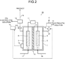
- Fig. 2 is a diagram illustrating an electrochemical reaction device IB.
- a first pressure adjuster 141 is disposed on a back pressure side of the first room 3 and a second pressure adjuster 142 may be additionally disposed on a back pressure side of the second room 5.
- the first pressure adjuster 141 is the same as the pressure adjuster 14 illustrated in Fig. 1 .
- a variable throttle, a flow rate control valve or the like is used as the second pressure adjuster 142. That is, the pressure in the second room 5 can be adjusted by regulating a flow rate of a fluid (a fluid including gas and liquid) flowing through the second discharge flow path 20.
- the explanation regarding the pressure adjuster 14 can be appropriately cited as other explanations regarding the first pressure adjuster 141 and the second pressure adjuster 142.
- the explanation of the electrochemical reaction device 1A can be appropriately cited regarding the same components as the electrochemical reaction device 1A.
- the second pressure adjuster 142 is provided at the second discharge flow path 20.
- a differential pressure between the first room 3 and the second room 5 can be adjusted by providing the second pressure adjuster 142. This can suppress breakage or the like of the diaphragm 6 due to the differential pressure between the first room 3 and the second room 5.
- the difference (differential pressure) between the pressure in the first room 3 and the pressure in the second room 5 is preferably adjusted within 0.5 MPa by the first pressure adjuster 141 and the second pressure adjuster 142.
- the regulation of the pressure in the first room 3 by the pressure adjuster 14 or the first pressure adjuster 141 is performed by sending a detection signal indicating temperature in the first reactor 7 detected by the temperature detector 15 to the controller 16 and controlling operation of the pressure adjuster 14 by the controller 16.
- the temperature detection uni 15 is disposed at a part capable of detecting at least one of the temperature in the first reactor 7, the temperature in the first room 3, and the temperature in the second room 5.
- a contact type or non-contact type temperature measuring device can be used as the temperature detector 15. In a case of the contact type temperature measuring device, it can be connected to at least one of the first reactor 7, the first room 3, and the second room 5.
- the temperature may be detected by a non-contact type device such as a non-contact thermometer or a thermography and calculation using a heating value data at a cell operation time which is previously obtained by an experiment or a simulation.
- the temperature of at least one of the first electrolytic solution 2 and the second electrolytic solution 4 discharged from the first reactor 7 may be detected to detect the temperature.
- the temperature detector 15 is electrically connected to the controller 16, and the controller 16 is electrically connected to the pressure adjuster 14. The temperature detector 15 outputs a detection signal to the controller 16.
- the controller 16 is electrically connected to the pressure adjuster 14 and the temperature detector 15.
- the controller 16 receives the detection signal (data signal) from the temperature detector 15 and outputs a control signal to the pressure adjuster 14.
- the controller 16 previously stores a request criterion of the data signal regarding a composition and an amount of a product, and the controller 16 outputs the control signal to the pressure adjuster 14 when the request criterion is not satisfied.
- the controller 16 is formed of a computer such as, for example, a personal computer or a microcomputer, and arithmetically processes the data signal from the temperature detector 15 and controls operation of the pressure adjuster 14 to adjuste pressure in the first room 3.
- a partial current density of a reduction product of an electrochemical reaction device largely changes due to unstable electric power supplied from renewable energy.
- Heat quantity of Joule heat generated at the first reactor 7 becomes large as the current density increases resulting in that the temperature in the first reactor 7 increases.
- control may be carried out by inputting a relationship between the lowering of the Faradaic efficiency and the lowering of the electrolysis efficiency in accordance with the temperature increase which is measured in advance to the controller 16.
- the control to increase the pressure is carried out.
- the control to lower the pressure may be carried out when the electric power supplied from the power supply 11 is lowered and the current density is lowered.
- the temperature in the first reactor 7 is preferably controlled within a range from room temperature (for example, 25°C) to 150°C where the electrolytic solution does not evaporate.
- the temperature is more preferably controlled to fall within a range from 60°C to 150°C, and further preferably controlled to be 80°C or more and 150°C or less.
- energy efficiency of a total system may be lowered because a cooling device such as a chiller is required.
- the temperature is higher than 150°C, water in the electrolytic solution is evaporated to increase resistance, and the electrolysis efficiency may be lowered.
- the current density of the cathode 8 is not particularly limited, but the current density is preferably higher to increase the production amount of the reduction product per unit area.
- the current density is preferably 100 mA/cm 2 or more and 1.5 A/cm 2 or less, and further preferably 300 mA/cm 2 or more and 700 mA/cm 2 or less.
- the current density is less than 100 mA/cm 2 , the production amount of the reduction product per unit area is low, and a large area is required.
- the current density exceeds 1.5 A/cm 2 , a side reaction of producing hydrogen increases to lower a reduction product concentration.
- a cooling mechanism may be provided at the first reactor 7 or in the vicinity thereof since the temperature increases to a proper temperature or more.
- the cooling mechanism may be achieved by either water cooling or air cooling.
- the temperature in the first reactor 7 is higher than the room temperature, the temperature may be controlled as it is as long as the temperature is 150°C or less.
- the electrolysis efficiency or the like is adjusted by lowering the temperature to the room temperature, energy loss becomes large.
- the first reactor 7 may be formed in an integral structure where a plurality of first reactors 7 are disposed to increase a reaction amount of the reduction catalyst and the production amount of the reduction product per unit area.
- the temperature in the first reactor 7 may increase due to a problem of radiation of Joule heat of an electrode.
- the reaction can be promoted without lowering at least one of the Faradaic efficiency and the electrolysis efficiency according to this arrangement.
- the first separation unit 12 is disposed to separate the reduction product from by-products such as carbon dioxide and hydrogen.
- a separation method is not particularly limited, but there can be used a membrane separation method, a chemisorption method by using amine or the like, a pressure swing adsorption method, a thermal swing adsorption method, and so on.
- a gas/liquid separation unit which separates gas containing the reduction product from the electrolytic solution can be disposed without arranging the first separation unit 12.
- the second separation unit 13 includes a gas/liquid separation tank, and it is disposed to separate produced oxygen from the electrolytic solution.
- the product of the reduction reaction of carbon dioxide is not limited to carbon monoxide but may be a production reaction of, for example, ethanol (C 2 H 5 OH), ethylene (C 2 H 4 ), ethane (C 2 H 6 ), methane (CH 4 ), methanol (CH 3 OH), acetic acid (CH 3 COOH), propanol (C 3 H 7 OH) ,or the like.
- the reduction reaction by the cathode 8 fluctuates depending on the temperatures of the cathode 8 and the first room 3. For example, there is a case where hydrogen gas is produced by the reduction reaction of water in addition to the above-described production reaction of carbon monoxide gas. A ratio between production amounts of carbon monoxide gas and hydrogen gas fluctuates depending on the temperatures of the cathode 8 and the first room 3, and an amount of hydrogen gas mixed in carbon monoxide gas being a main target product may increase in some cases.
- the kind or the like of the reduction catalyst constituting the cathode 8 is selected to make an organic compound such as ethanol, ethylene, or ethane a main target product in place of carbon monoxide gas in some cases.
- the production amount of carbon monoxide increases and a production amount of the organic compound decreases depending on the temperatures of the cathode 8 and the first room 3.
- the fluctuations in the composition and the production amount of the reduction product in accordance with the above-described fluctuation in the temperatures of the cathode 8 and the first room 3 are detected by the temperature detector 15.
- the pressure adjuster 14 is controlled based on the detection result by the temperature detector 15, whereby the pressure in the first room 3 is adjusted as described above.
- This adjusts the production amount of the reduction product, and adjusts the composition and the production amount of the reduction product to desired states. Accordingly, it becomes possible to suppress the successive fluctuations in the production amount and the composition of the reduction product of carbon dioxide due to the changes in the temperatures of the cathode 8 and the first room 3 to thereby enhance availability and utility value of the reduction product.
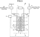
- Fig. 3 is a diagram illustrating an electrochemical reaction device 1C.
- the electrochemical reaction device 1C illustrated in Fig. 3 is different from the electrochemical reaction device 1B in the first arrangement in a contact type of gas containing carbon dioxide (simply described as CO 2 gas in some cases) or the first electrolytic solution 2 (cathode solution) containing carbon dioxide with the cathode 8, a contact type of the second electrolytic solution 4 (anode solution) containing water with the anode 9, and a connection mode of the cathode 8 and the anode 9 with the power supply 11.
- each unit other than the above for example, the concrete configurations of the cathode 8, the anode 9, the diaphragm 6, the first electrolytic solution 2, the second electrolytic solution 4, the power supply 11 and so on, the separation of the product, the detection of the temperature, the pressure regulation based on the detection result of the temperature and so on are the same as those in the first arrangement.
- gas containing carbon dioxide can be used in place of the first electrolytic solution 2 containing carbon dioxide in the second arrangement. This arrangement can be appropriately combined with other arrangements.
- the electrochemical reaction device 1C illustrated in Fig. 3 includes the electrochemical reaction cell 10 including the cathode 8, the anode 9, the diaphragm 6, a first flow path 31 for allowing gas containing carbon dioxide (simply described as CO 2 gas in some cases) or the first electrolytic solution 2 (cathode solution) containing carbon dioxide to flow therethrough, a second flow path 32 for allowing the second electrolytic solution 4 (anode solution) containing water to flow therethrough, a first current collector plate 33 electrically connected to the cathode 8, and a second current collector plate 34 electrically connected to the anode 9.
- the first and second current collector plates 33, 34 of the electrochemical reaction cell 10 are connected to the power supply 11.
- the temperature detector 15 is connected to the first room 3.
- the first flow path 31 is disposed to face the cathode 8 and forms the first room 3.
- a non-illustrated gas or solution tank, pump, and so on are connected to the first flow path 31 and configured such that the CO 2 gas or the cathode solution flows through the first flow path 31 to be supplied to the cathode 8.
- Carbon dioxide in the CO 2 gas or the cathode solution passed through the cathode 8 is reduced by the cathode 8.
- Gas or a solution containing the reduction product of carbon dioxide is sent to the first separation unit 12.
- the first pressure adjuster 141 is provided between the first flow path 31 and the first separation unit 12.
- the second flow path 32 is disposed to face the anode 9 and forms the second room 5.
- the second pressure adjuster 142 is provided between the second flow path 32 and the second separation unit 13.
- a non-illustrated solution tank, pump, and so on are connected to the second flow path 32 and configured such that the anode solution flows through the second flow path 32 to be supplied to the anode 9. Water in the anode solution passed through the anode 9 is oxidized by the anode 9. A solution containing an oxidation product of water is sent to the second separation unit 13.
- the first pressure adjuster 141 and the second pressure adjuster 142 are controlled based on a detection signal of the temperature detector 15 at the first reactor 7 including the first flow path 31, the second flow path 32, the diaphragm 6, the cathode 8, and the anode 9 to adjust pressure in the first flow path 31.
- This adjusts a potential of the cathode 8 to be a desired potential, and adjusts a composition and a production amount of the reduction product to desired states. Accordingly, it becomes possible to suppress the successive fluctuations in the production amount and the composition of the reduction product of carbon dioxide due to the changes in the temperatures of the first room 3 and the second room 5 to thereby enhance availability and utility value of the reduction product.
- a concentration of carbon dioxide introduced into the first room 3 is preferably higher, but operation is possible at a concentration of 5% or more and 20% or less in volume percent.
- concentration of carbon dioxide is 5% or more and 20% or less in volume percent, Faradaic efficiency and electrolysis efficiency can be increased by increasing the pressure to increase partial pressure of carbon dioxide.
- the pressure of carbon dioxide is preferably 3 atm or more and 6.4 MPa or less.
- a fluid such as gas or an electrolytic solution containing carbon dioxide is introduced into the first room 3 from, for example, a discharge source discharging carbon dioxide.
- a difference between the temperature of carbon dioxide introduced into the first room 3 and the temperature in the first reactor 7 is preferably within 20°C.
- the temperature in the first reactor 7 in the vicinity of an introducing part is lowered to cause nonuniform temperature in the first reactor 7, resulting in that a current density of the carbon dioxide reduction at an electrode becomes nonuniform.
- the electrolysis efficiency is thereby lowered in some cases.
- the temperature of the introduced carbon dioxide is higher than the temperature in the first reactor 7, the temperature in the first reactor 7 increases, and cooling is required.
- the temperature difference is therefore further preferably within 10°C.
- the temperature of the carbon dioxide introduced under such a condition is preferably 80°C or more and 140°C or less.
- the temperature is further preferably 80°C or more and 120°C or less. Energy efficiency further improves when the temperature is 80°C or more and 120°C or less.
- the first reactor 7 can be heated by using the heat of the introduced carbon dioxide. The total energy efficiency is thereby improved.
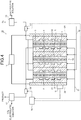
- Fig. 4 is a diagram illustrating an example of an electrochemical reaction device ID.
- a plurality of first reactors 7 are disposed to be formed in an integral structure.
- a production amount of a reduction product per unit area can be increased by arranging the plurality of first reactors 7.
- the number of disposed first reactors 7 is not particularly limited, but it is preferably configured by arranging three pieces or more and 40 pieces or less per one unit, and more preferably three pieces or more and 20 pieces or less of the first reactors 7 to increase a reaction amount per unit area.
- the reaction amount per unit area is small and the production amount cannot be largely increased.
- it exceeds 40 pieces it becomes difficult to control the temperature.
- the explanation of other electrochemical reaction devices such as the electrochemical reaction device 1C can be appropriately cited as other explanations of the electrochemical reaction device ID.
- Fig. 5 is a diagram illustrating an electrochemical reaction device IE. This arrangement can be appropriately combined with other arrangements, and explanations of the same components as those of the electrochemical reaction device 1A to the electrochemical reaction device ID can be appropriately cited.
- the electrochemical reaction cell 10 is, for example, any of the electrochemical reaction cells 10 illustrated in Fig. 1 to Fig. 4 .
- a second reactor 21 can be connected to the first reactor 7 of the electrochemical reaction cell 10.
- the second reactor 21 is connected in order to further make a product obtained by reducing carbon dioxide at the first reactor 7 react.
- the second rection unit 21 is not particularly limited as long as the reduction product produced at the first reactor 7 can be made react with other substances, and the reaction of the reduction product includes reactions such as a chemical reaction, an electrochemical reaction, and a biological conversion reaction by algae, enzyme, yeast, bacteria, and the like.
- the electrochemical reaction, the biological conversion reaction by bacteria or the like at least one parameter between reaction efficiency and a reaction rate improves when the temperature is higher than room temperature.
- the reduction product introduced into the second reactor 21 is introduced at temperature of 60°C or more and 150°C or less, energy conversion efficiency of the electrochemical reaction device 1E can be improved.
- the efficiency can be further improved when the reduction product is introduced into the second reactor 21 at the temperature of 60°C or more and 100°C or less because the reaction of the biological conversion reaction by bacteria or the like promotes the most efficiently at the temperature around 80°C.
- the temperature or pressure of the second reactor 21 may be increased by applying energy from the outside to improve the reaction efficiency.
- the reduction product may include carbon dioxide, carbon monoxide, and hydrogen obtained by electrolysis of water.
- a hydrogen concentration can be arbitrary adjusted depending on uses.
- carbon dioxide or the like is separated by the first separation unit 12 while remaining the reduction product and hydrogen as a mixture.
- hydrogen is not used, only the reduction product is separated.
- hydrogen as a side reaction can be used at the second reactor 21 as a valuable resource by regulating the hydrogen concentration to be approximately double with respect to the number of moles of carbon monoxide.
- the hydrogen concentration of the reduction product can be adjusted within a range of 0.1% or more and 5% or less in volume percent by suppressing the side reaction of hydrogen. It is thereby possible to use the device as a carbon monoxide production device providing high concentration carbon monoxide.
- the electrochemical reaction device 1C illustrated in Fig. 3 was manufactured. First, changes in Faradaic efficiency and electrolysis efficiency were measured by controlling the pressures in the first room 3 and the second room 5 by using the electrochemical reaction device 1C when the temperature in the first reactor 7 increased.
- a stainless reaction container was used as the first reactor 7.
- a PTFE porous membrane was disposed in the middle of the reaction container to separate between the first room 3 and the second room 5.
- One where a gold catalyst is supported on carbon particles on carbon paper was used as the cathode 8.
- One where iridium catalyst adheres to titanium mesh was used as the anode 9.
- a 0.1 M KHCO 3 aqueous solution was used for the second electrolytic solution to be supplied to the second room 5.
- Gas containing carbon dioxide was supplied to the first room 3.
- a DC stabilized power supply was used as the power supply 11 for a verification experiment and was connected to the cathode 8 and the anode 9.
- a temperature measuring thermocouple was used as the temperature detector 15.
- a relief valve was used as the pressure adjuster 14.
- Electrolysis efficiency of a reduction product produced by a reduction reaction of carbon dioxide and potential dependence of pressure were evaluated in advance by measurement using a potentiostat. Gas components discharged from the cathode 8 side were analyzed by a gas chromatography apparatus. The gas components observed by the gas chromatography apparatus were carbon monoxide, hydrogen, and carbon dioxide. Then, the electrolysis efficiency over time of carbon monoxide produced at the cathode 8 was calculated. Faradaic efficiency of carbon monoxide (CO Faradaic efficiency) was calculated from the following expression. Note that a production rate of carbon monoxide (CO production rate) was obtained from the gas chromatography analysis result, and a value observed by an ammeter was used as a current value. Besides, the number of reaction electrons was set to 2.
- CO FARADAIC EFFICIENCY % CO PRODUCTION RATE mol / s ⁇ FARADAY CONSTANT ⁇ NUMBER OF REACTION ELECTRONS CURRENT VALUE A
- a current density of carbon dioxide reduction was 300 mA/cm 2
- the electrolysis efficiency was 27% and the CO Faradaic efficiency was 85% at room temperature under the atmospheric pressure, but the electrolysis efficiency decreased to be 25% and the CO Faradaic efficiency decreased to 56% at 80°C under atmospheric pressure.
- the electrolysis efficiency increased to 32% and the CO Faradaic efficiency increased to 84% when the conditions were adjusted by the first pressure adjuster 141 and the second pressure adjuster 142 to be 80°C under 2 atm.
- the power supply 11 using renewable energy was used and a reduction test of carbon dioxide was carried out.
- an amount and a composition of a product at the cathode 8 were monitored by operating a temperature monitor as the temperature detector 15, and a detection signal thereof was sent to the controller 16 to control the pressure adjuster 14.
- the result showed that, though there was a fluctuation in the temperature, it was verified that the fluctuations in the amount and the composition of the product at the cathode 8 were suppressed based on the regulation of the pressure in the first room 3.
Landscapes
- Chemical & Material Sciences (AREA)
- Engineering & Computer Science (AREA)
- Organic Chemistry (AREA)
- Chemical Kinetics & Catalysis (AREA)
- Electrochemistry (AREA)
- Materials Engineering (AREA)
- Metallurgy (AREA)
- Inorganic Chemistry (AREA)
- Automation & Control Theory (AREA)
- Analytical Chemistry (AREA)
- Electrolytic Production Of Non-Metals, Compounds, Apparatuses Therefor (AREA)
Abstract
An electrochemical reaction device includes: a first reactor including a first room and a second room, the first room being configured to store a gas containing carbon dioxide or a first electrolytic solution containing carbon dioxide, and the second room being configured to store a second electrolytic solution containing water; a cathode disposed in the first room, the cathode being configured to reduce the carbon dioxide and thus produce a reduction product; an anode disposed in the second room, the anode being configured to oxidize the water and thus produce an oxidation product; a first pressure adjuster configured to adjust pressure in the first room; a temperature detector configured to detect a temperature in the first reactor to form a detection signal; and a controller configured to control the pressure adjuster in accordance with the detection signal from the temperature detector.
Description
- Arrangements described herein relate generally to an electrochemical reaction device.
- In recent years, there is a concern over depletion of fossil fuel resources such as petroleum and coal, and expectations for sustainable renewable energy increases. From the viewpoint of such energy problems, environmental problems and so on, an artificial photosynthesis technology is under development which electrochemically reduces carbon dioxide using renewable energy such as sunlight to generate a stockable chemical energy source. An electrochemical reaction device enabling the artificial photosynthesis technology includes, for example, an anode that oxidizes water (H2O) to produce oxygen (O2), and a cathode that reduces carbon dioxide (CO2) to produce a carbon compound. The anode and the cathode of the electrochemical reaction device are generally connected to a power supply derived from renewable energy such as solar power generation, hydroelectric power generation, wind power generation, geothermal power generation or the like.
- The cathode of the electrochemical reaction device is disposed, for example, to be immersed in water in which carbon dioxide is dissolved or to be in contact with water which flows through a flow path and in which carbon dioxide is dissolved. The cathode obtains reduction potential for carbon dioxide from the power supply derived from renewable energy and thereby reduces carbon dioxide to produce carbon compounds such as carbon monoxide (CO), formic acid (HCOOH), methanol (CH3OH), methane (CH4), ethanol (C2H5OH), ethane (C2H6), ethylene (C2H4), and ethylene glycol (C2H6O2).
- When a large amount of carbon dioxide is electrochemically reduced by using the above-described renewable energy, temperature in a reactor increases due to Joule heat. Since an amount of carbon dioxide dissolved in water depends on the temperature, utility value is lowered due to change in the amount of carbon dioxide in water. Further, there is a problem that electric power is likely to fluctuate due to change in weather, wind condition or the like and applied potential to the cathode is likely to fluctuate in accordance with the change. The Joule heat also fluctuates due to the change in the applied potential to the cathode to cause a problem that the temperature in the reactor during operation fluctuates. This becomes a factor to decrease availability and utility value of the reduction product of carbon dioxide. As a method to solve the problem, the electrochemical reaction device is experimentally operated by using a power supply such as a potentiostat capable of applying a constant potential to the cathode (three-electrode system), but this loses advantages owing to the utilization of the renewable energy and results in a problem in terms of cost and efficiency.
-
- Reference 1: Japanese Unexamined Patent Application Publication No.
2017-48442 - Reference 2: Japanese Translation of PCT International Application Publication No.
2017-31467 - Reference 3: Colin Oloman et al., "Electrochemical Processing of Carbon Dioxide" ChemSusChem 2008, 1, 385-391
-
-
Fig. 1 is a diagram illustrating anelectrochemical reaction device 1A. -
Fig. 2 is a diagram illustrating anelectrochemical reaction device 1B. -
Fig. 3 is a diagram illustrating anelectrochemical reaction device 1C. -
Fig. 4 is a diagram illustrating an electrochemical reaction device ID. -
Fig. 5 is a diagram illustrating an electrochemical reaction device IE. - A problem to be solved by the present invention is to provide an electrochemical reaction device capable of suppressing successive fluctuations in a production amount and a composition of a reduction product of carbon dioxide due to increase and fluctuation in temperature in a reaction unit caused by Joule heat when a large amount of carbon dioxide is reduced.
- An electrochemical reaction device includes: a first reactor including a first room and a second room, the first room being configured to store a gas containing carbon dioxide or a first electrolytic solution containing carbon dioxide, and the second room being configured to store a second electrolytic solution containing water; a cathode disposed in the first room, the cathode being configured to reduce the carbon dioxide and thus produce a reduction product; an anode disposed in the second room, the anode being configured to oxidize the water and thus produce an oxidation product; a first pressure adjuster configured to adjust pressure in the first room; a temperature detector configured to detect a temperature in the first reactor to form a detection signal; and a controller configured to control the pressure adjuster in accordance with the detection signal from the temperature detector.
- Electrochemical reaction devices in arrangements will be described hereinafter with reference to the drawings. Substantially the same components are denoted by the same reference signs and explanation thereof may be omitted in some cases in the arrangements described below. The drawings are schematic, and a relationship between a thickness and a planar size, thickness proportions of the respective portions, and the like are sometimes different from actual ones.
-
Fig. 1 is a diagram illustrating anelectrochemical reaction device 1A. Theelectrochemical reaction device 1A includes: anelectrochemical reaction cell 10 including afirst reactor 7 including afirst room 3 configured to store a firstelectrolytic solution 2 containing carbon dioxide, asecond room 5 configured to store a secondelectrolytic solution 4 containing water, and adiaphragm 6 configured to divide between thefirst room 3 and thesecond room 5, acathode 8 disposed in thefirst room 3 and configured to produce a reduction product by reducing carbon dioxide, and ananode 9 disposed in thesecond room 5 and configured to produce an oxidation product by oxidizing water; apower supply 11 connected to thecathode 8 and theanode 9; afirst separation unit 12 configured to separate the reduction product produced at thefirst room 3 from the firstelectrolytic solution 2; asecond separation unit 13 configured to separate the oxidation product produced at thesecond room 5 from the secondelectrolytic solution 4; apressure adjuster 14 configured to adjust pressure in thefirst room 3; atemperature detector 15 configured to detect temperature in thefirst room 3; and acontroller 16 configured to control thepressure adjuster 14 based on a detection signal of thetemperature detector 15. - The
first reactor 7 has thefirst room 3 and thesecond room 5 divided by thediaphragm 6 capable of moving ions such as hydrogen ions (H+) and hydroxide ions (OH-). Thefirst reactor 7 may be made of a container of, for example, quartz white plate glass, polystyrol, polymethacrylate or the like. A material transmitting light may be used for a part of thefirst reactor 7, and a resin material may be used for the remainder. Examples of the resin material include, for example, polyetheretherketone (PEEK), polyamide (PA), polyvinylidene fluoride (PVDF), polyacetal (POM) (copolymer), polyphenyleneether (PPE), acrylonitrile-butadiene-styrene copolymer (ABS), polypropylene (PP), polyethylene (PE) and so on. - The
cathode 8 is disposed in thefirst room 3, and the firstelectrolytic solution 2 is stored such that thecathode 8 is in contact with the firstelectrolytic solution 2. The firstelectrolytic solution 2 functions as a cathode solution and contains carbon dioxide as a substance to be reduced. The firstelectrolytic solution 2 may contain hydrogen ions, and is preferably an aqueous solution. - The
anode 9 is disposed in thesecond room 5, and the secondelectrolytic solution 4 is stored such that theanode 9 is in contact with the secondelectrolytic solution 4. The secondelectrolytic solution 4 functions as an anode solution and contains water as a substance to be oxidized. The secondelectrolytic solution 4 may contain an aqueous solution such as an alcohol aqueous solution, an aqueous solution of an organic substance such as amine. - It is possible to change reactivity so as to change selectivity of a substance to be reduced and a proportion of a produced chemical substance by changing an amount of water and electrolytic solution components contained in the first
electrolytic solution 2 and the secondelectrolytic solution 4. The firstelectrolytic solution 2 and the secondelectrolytic solution 4 may contain redox couples as needed. Examples of the redox couple include, for example, Fe3+/Fe2+ and 103-/I-. - The
first room 3 and thesecond room 5 may each include a space part for accommodating gas contained in a reactant and a product. To thefirst room 3, a firstsupply flow path 17 for supplying the firstelectrolytic solution 2 is connected, and thefirst separation unit 12 is further connected through a firstdischarge flow path 19 for discharging a fluid such as gas or liquid from thefirst room 3. To thesecond room 5, a secondsupply flow path 18 for supplying the secondelectrolytic solution 4 is connected, and thesecond separation unit 13 is further connected through a seconddischarge flow path 20 for discharging a fluid such as gas or liquid from thesecond room 5. - The first
electrolytic solution 2 and the secondelectrolytic solution 4 may be electrolytic solutions containing different substances or may be electrolytic solutions containing the same substance. In a case where the firstelectrolytic solution 2 and the secondelectrolytic solution 4 contain the same substance and the same solvent, the firstelectrolytic solution 2 and the secondelectrolytic solution 4 may be regarded as one electrolytic solution. Besides, the pH of the secondelectrolytic solution 4 is preferably higher than the pH of the firstelectrolytic solution 2. This makes the hydrogen ions, the hydroxide ions and so on easy to move. Further, a liquid junction potential due to the difference in pH can effectively promote an oxidation-reduction reaction. - The first
electrolytic solution 2 is preferably a solution with high absorptance of carbon dioxide. An existing form of carbon dioxide in the firstelectrolytic solution 2 is not always limited to a state of being dissolved therein, but carbon dioxide in an air bubble state may exist to be mixed in the firstelectrolytic solution 2. - Examples of the electrolytic solution containing carbon dioxide include, for example, aqueous solutions containing hydrogencarbonates and carbonates such as lithium hydrogen carbonate (LiHCO3), sodium hydrogen carbonate (NaHCO3), potassium hydrogen carbonate (KHCO3), sodium carbonate (Na2CO3), potassium carbonate (K2CO3), and cesium hydrogen carbonate(CsHCO3), phosphoric acid, boric acid, and so on. The electrolytic solution containing carbon dioxide may contain alcohols such as methanol, ethanol, and acetone, or may be an alcohol solution. The first
electrolytic solution 2 may be an electrolytic solution containing a carbon dioxide absorbent that lowers a reduction potential for carbon dioxide, has high ion conductivity, and absorbs carbon dioxide. - A solution containing water, for example, an aqueous solution containing an arbitrary electrolyte may be used as the second
electrolytic solution 4. The solution is preferably an aqueous solution that promotes the oxidation reaction of water. Examples of the aqueous solution containing the electrolyte include, for example, aqueous solutions containing phosphate ion (PO4 2- ), borate ion (BO3 3-), sodium ion (Na+), potassium ion (K+), calcium ion (Ca2+), lithium ion (Li+), cesium ion (Cs+), magnesium ion (Mg2+), chloride ion (Cl-), hydrogen carbonate ion (HCO3 -), carbonate ion (CO3 -), hydroxide ion (OH-) and the like. - The first
electrolytic solution 2 and the secondelectrolytic solution 4 may contain, for example, ionic liquids made of salts of cations such as imidazolium ions or pyridinium ions and anions such as BF4 - or PF6 - and in a liquid state in a wide temperature range, or aqueous solutions thereof. Examples of other electrolytic solutions include amine solutions such as ethanolamine, imidazole, and pyridine, or aqueous solutions thereof. Examples of amine include primary amine, secondary amine, tertiary amine, and the like. The electrolytic solutions may be high in ion conductivity and have properties of absorbing carbon dioxide and characteristics of lowering reduction energy. - Examples of the primary amine include methylamine, ethylamine, propylamine, butylamine, pentylamine, hexylamine and the like. Hydrocarbons of the amine may be substituted by alcohol, halogen and the like. Examples of amine whose hydrocarbons are substituted include methanolamine, ethanolamine, chloromethylamine and the like. Further, an unsaturated bond may exist. These hydrocarbons are also the same in the secondary amine and the tertiary amine.
- Examples of the secondary amine include dimethylamine, diethylamine, dipropylamine, dibutylamine, dipentylamine, dihexylamine, dimethanolamine, diethanolamine, dipropanolamine and the like. The substituted hydrocarbons may be different. This also applies to the tertiary amine. For example, examples with different hydrocarbons include methylethylamine, methylpropylamine and the like.
- Examples of the tertiary amine include trimethylamine, triethylamine, tripropylamine, tributylamine, trihexylamine, trimethanolamine, triethanolamine, tripropanolamine, tributanolamine, tripropanolamine, triexanolamine, methyldiethylamine, methyldipropylamine and the like.
- Examples of the cation of the ionic liquid include 1-ethyl-3-methylimidazolium ion, 1-methyl-3-propylimidazolium ion, 1-butyl-3-methylimidazole ion, 1-methyl-3-pentylimidazolium ion, 1-hexyl-3-methylimidazolium ion and the like.
- A second place of the imidazolium ion may be substituted. Examples of the cation of the imidazolium ion whose second place is substituted include 1-ethyl-2,3-dimethylimidazolium ion, 1,2-dimethyl-3-propylimidazolium ion, 1-butyl-2,3-dimethylimidazolium ion, 1,2-dimethyl-3-pentylimidazolium ion, 1-hexyl-2,3-dimethylimidazolium ion and the like.
- Examples of the pyridinium ion include methylpyridinium, ethylpyridinium, propylpyridinium, butylpyridinium, pentylpyridinium, hexylpyridinium and the like. In both of the imidazolium ion and the pyridinium ion, an alkyl group may be substituted, or an unsaturated bond may exist.
- Examples of the anion include fluoride ion (F-), chloride ion (CI-), bromide ion (Br), iodide ion (I-), BF4 -, PF6 -, CF3COO-, CF3SO3 -, NO3 -, SCN-, (CF3SO2)3C-, bis(trifluoromethoxysulfonyl)imide, bis(trifluoromethoxysulfonyl)imide, bis(perfluoroethylsulfonyl)imide and the like. Dipolar ions in which the cations and the anions of the ionic liquid are coupled by hydrocarbons may be used. Note that a buffer solution such as a potassium phosphate solution may be supplied to the
first room 3 and thesecond room 5. - A membrane capable of selectively allowing the anion or the cation to pass therethrough is used for the
diaphragm 6. This makes it possible to make the firstelectrolytic solution 2 and the secondelectrolytic solution 4 which are in contact with thecathode 8 and theanode 9 respectively electrolytic solutions containing different substances, and to promote the reduction reaction and the oxidation reaction depending on the difference in ionic strength, the difference in pH or the like. Thediaphragm 6 can be used to separate the firstelectrolytic solution 2 from the secondelectrolytic solution 4. Thediaphragm 6 may have a function of allowing part of ions contained in the firstelectrolytic solution 2 and the secondelectrolytic solution 4 where thecathode 8 and theanode 9 are respectively immersed to permeate, namely, a function of blocking one or more kinds of ions contained in the firstelectrolytic solution 2 and the secondelectrolytic solution 4. This can differ, for example, the pH or the like between the firstelectrolytic solution 2 and the secondelectrolytic solution 4. - An ion exchange membrane such as, for example, NEOSEPTA (registered trademark) of ASTOM Corporation, Selemion (registered trademark), Aciplex (registered trademark) of ASAHI GLASS CO., LTD., Fumasep (registered trademark), fumapem (registered trademark) of Fumatech GmbH, Nafion (registered trademark) being a fluorocarbon resin made by sulfonating and polymerizing tetrafluoroethylene of E.I. du Pont de Nemours and Company, lewabrane (registered trademark) of LANXESS AG, IONSEP (registered trademark) of IONTECH Inc., Mustang (registered trademark) of PALL Corporation, ralex (registered trademark) of mega Corporation, Gore-Tex (registered trademark) of Gore-Tex Co., Ltd. can be used as the
diaphragm 6. Besides, the ion exchange membrane may be composed using a membrane having hydrocarbon as a basic skeleton or a membrane having an amine group in anion exchange. When the firstelectrolytic solution 2 and the secondelectrolytic solution 4 are different in pH, the electrolytic solutions can be used while stably keeping their pHs by using a bipolar membrane made by stacking a cation exchange membrane and an anion exchange membrane. - Other than the ion exchange membrane, for example, porous membranes of polymer materials such as a silicone resin, fluorine-based resins (perfluoroalkoxyalkane (PFA), perfluoroethylene propene copolymer (FEP), polytetrafluoroethylene (PTFE), ethylene-tetrafluoroethylene copolymer (ETFE), polyvinylidene fluoride (PVDF), polychlorotrifluoroethylene (PCTFE), ethylene-chlorotrifluoroethylene copolymer (ECTFE) and the like), paper, and ceramics, filler filled with glass filter, agar and the like, insulating porous bodies of zeolite and oxide and the like may be used as the
diaphragm 6. In particular, a hydrophilic porous membrane never causes clogging due to air bubbles and is thus preferable as thediaphragm 6. - The
cathode 8 is an electrode that reduces carbon dioxide to produce a reduction product such as a carbon compound. Thecathode 8 is disposed in thefirst room 3 and immersed in the firstelectrolytic solution 2 supplied to thefirst room 3. Thecathode 8 contains a reduction catalyst for producing the reduction product such as the carbon compound by the reduction reaction of, for example, carbon dioxide. Examples of the reduction catalyst include a material that lowers activation energy for reducing carbon dioxide. In other words, a material that lowers an overvoltage when the carbon compound is produced by the reduction reaction of carbon dioxide can be cited. - The
cathode 8 contains, for example, a metal material or a carbon material. For example, a metal such as gold, aluminum, copper, silver, platinum, palladium, zinc, mercury, indium, or nickel, or an alloy containing the metal and the like can be used as the metal material. For example, graphene, carbon nanotube (CNT), fullerene, ketjen black or the like can be used as the carbon material. Note that the reduction catalyst is not limited to the above but, for example, a metal complex such as a Ru complex or a Re complex, or an organic molecule having an imidazole skeleton or a pyridine skeleton may be used as the reduction catalyst. The reduction catalyst may be a mixture of a plurality of materials. Thecathode 8 may have, for example, a structure having the reduction catalyst in a thin film shape, a mesh shape, a particle shape, a wire shape or the like provided on a conductive substrate. - Examples of the reduction product produced by the reduction reaction at the
cathode 8 include, for example, carbon compounds such as carbon monoxide (CO), formic acid (HCOOH), methane (CH4), methanol (CH3OH), ethane (C2H6), ethylene (C2H4), ethanol (C2H5OH), formaldehyde (HCHO), and ethylene glycol (C2H6O2) though different depending on the kind or the like of the reduction catalyst. Further, at thecathode 8, a side reaction of producing hydrogen (H2) by the reduction reaction of water may occur simultaneously with the reduction reaction of carbon dioxide. - The
anode 9 is an electrode that oxidizes water to produce oxygen. Theanode 9 is disposed in thesecond room 5 and immersed in the secondelectrolytic solution 4 supplied to thesecond room 5. Theanode 9 contains an oxidation catalyst for producing oxygen by oxidizing water. A material that lowers activation energy for oxidizing water, in other words, a material that lowers an overvoltage when oxygen and hydrogen ions are produced by the oxidation reaction of water is used as the oxidation catalyst. - The oxidation catalyst contains metals such as, for example, ruthenium, iridium, platinum, cobalt, nickel, iron, manganese. Further, a binary metal oxide, a ternary metal oxide, a quaternary metal oxide or the like can be used. Examples of the binary metal oxide include, for example, manganese oxide (Mn-O), iridium oxide (Ir-O), nickel oxide (Ni-O), cobalt oxide (Co-O), iron oxide (Fe-O), tin oxide (Sn-O), indium oxide (In-O), ruthenium oxide (Ru-O) and the like. Examples of the ternary metal oxide include, for example, Ni-Fe-O, Ni-Co-O, La-Co-O, Ni-La-O, Sr-Fe-O and the like. Examples of the quaternary metal oxide include, for example, Pb-Ru-Ir-O, La-Sr-Co-O and the like. Note that the oxidation catalyst is not limited to the above, but a metal hydroxide containing cobalt, nickel, iron, manganese or the like, or a metal complex such as a Ru complex or a Fe complex may be used as the oxidation catalyst. Further, a plurality of materials may be mixed together for use.
- The
anode 9 may be composed of a composite material containing both the oxidation catalyst and a conductive material. Examples of the conductive material include: for example, carbon materials such as carbon black, activated carbon, fullerene, carbon nanotube, graphene, ketjen black, diamond; transparent conductive oxides such as indium tin oxide (ITO), zinc oxide (ZnO), fluorine-doped tin oxide (FTO), aluminum-doped zinc oxide (AZO), antimony-doped tin oxide (ATO); metals such as copper (Cu), aluminum (Al), titanium (Ti), nickel (Ni), silver (Ag), tungsten (W), cobalt (Co), gold (Au); and alloys each containing at least one of the metals. Theanode 9 may have a structure having, for example, the oxidation catalyst in a thin film shape, a mesh shape, a particle shape, a wire shape or the like provided on a conductive substrate. For example, a metal material containing titanium, titanium alloy, or stainless steel is used as the conductive substrate. - The
power supply 11 is able to supply electric power to make theelectrochemical reaction cell 10 cause the oxidation-reduction reaction, and is electrically connected to thecathode 8 and theanode 9. The electric energy supplied from thepower supply 11 is used to cause the reduction reaction by thecathode 8 and the oxidation reaction by theanode 9. Thepower supply 11 and thecathode 8 are connected and thepower supply 11 and theanode 9 are connected, for example, by wiring. Electric equipment such as an inverter, a converter, a battery may be installed between theelectrochemical reaction cell 10 and thepower supply 11 as needed. A drive system of theelectrochemical reaction cell 10 may be a constant-voltage system or may be a constant-current system. - The
power supply 11 may be a normal commercial power supply, battery or the like, or may be a power supply that supplies electric energy obtained by converting renewable energy. Examples of the power supply include a power supply that converts kinetic energy or potential energy such as wind power, water power, geothermal power, tidal power to electric energy, a power supply such as a solar cell including a photoelectric conversion element that converts light energy to electric energy, a power supply such as a fuel cell or a storage battery that converts chemical energy to electric energy, an apparatus that converts vibrational energy such as sound to electric energy, and so on. The photoelectric conversion element has a function of performing charge separation by emitted light energy of sunlight or the like. Examples of the photoelectric conversion element include a pin-junction solar cell, a pn-junction solar cell, an amorphous silicon solar cell, a multijunction solar cell, a single crystal silicon solar cell, a polycrystalline silicon solar cell, a dye-sensitized solar cell, an organic thin-film solar cell, and the like. The photoelectric conversion element may be stacked on at least one of thecathode 8 and theanode 9 inside thefirst reactor 7. - The reduction product produced at the
cathode 8 is sent through the firstdischarge flow path 19 to thefirst separation unit 12. In thefirst separation unit 12, carbon monoxide (CO) being a gaseous product, or formic acid (HCOOH), methane (CH4), methanol (CH3OH), ethane (C2H6), ethylene (C2H4), ethanol (C2H5OH), formaldehyde (HCHO), ethylene glycol (C2H6O2) or the like being a liquid product is separated from the firstelectrolytic solution 2. When the reduction reaction of water being the side reaction of the reduction reaction of carbon dioxide occurs, hydrogen produced therefrom is also separated from the firstelectrolytic solution 2. Further, the oxidation product produced at theanode 9 is sent through the seconddischarge flow path 20 to thesecond separation unit 13. In thesecond separation unit 13, oxygen (O2) being a gaseous product is mainly separated from the secondelectrolytic solution 4. - The first
discharge flow path 19 is provided with thepressure adjuster 14 that adjusts the pressure in thefirst room 3. Thepressure adjuster 14 is disposed on a back pressure side (an outlet side) of thefirst room 3. For example, a variable throttle, a flow rate control valve or the like is used as thepressure adjuster 14. That is, the pressure in thefirst room 3 can be adjusted by regulating a flow rate of a fluid (a fluid including gas and liquid) flowing through the firstdischarge flow path 19. The pressure in thefirst room 3 is preferably set to the pressure which does not liquefy carbon dioxide, and concretely, it is preferably adjusted in a range of 0. 1 MPa or more and 6.4 MPa or less. If the pressure in thefirst room 3 is less than 0.1 MPa, reduction reaction efficiency of carbon dioxide may decrease. If the pressure in thefirst room 3 exceeds 6.4 MPa, carbon dioxide is liquefied and the reduction reaction efficiency of carbon dioxide may decrease. - Increasing or decreasing the pressure in the
first room 3 can adjust the amount and kind of the reduction product produced at thecathode 8. That is, regulating the pressure in thefirst room 3 to change partial pressure of carbon dioxide being reacting species, thereby enabling regulation of the carbon dioxide amount near thecathode 8. -
Fig. 2 is a diagram illustrating an electrochemical reaction device IB. As illustrated inFig. 2 , afirst pressure adjuster 141 is disposed on a back pressure side of thefirst room 3 and asecond pressure adjuster 142 may be additionally disposed on a back pressure side of thesecond room 5. Thefirst pressure adjuster 141 is the same as thepressure adjuster 14 illustrated inFig. 1 . For example, a variable throttle, a flow rate control valve or the like is used as thesecond pressure adjuster 142. That is, the pressure in thesecond room 5 can be adjusted by regulating a flow rate of a fluid (a fluid including gas and liquid) flowing through the seconddischarge flow path 20. The explanation regarding thepressure adjuster 14 can be appropriately cited as other explanations regarding thefirst pressure adjuster 141 and thesecond pressure adjuster 142. Besides, the explanation of theelectrochemical reaction device 1A can be appropriately cited regarding the same components as theelectrochemical reaction device 1A. - The
second pressure adjuster 142 is provided at the seconddischarge flow path 20. A differential pressure between thefirst room 3 and thesecond room 5 can be adjusted by providing thesecond pressure adjuster 142. This can suppress breakage or the like of thediaphragm 6 due to the differential pressure between thefirst room 3 and thesecond room 5. The difference (differential pressure) between the pressure in thefirst room 3 and the pressure in thesecond room 5 is preferably adjusted within 0.5 MPa by thefirst pressure adjuster 141 and thesecond pressure adjuster 142. - The regulation of the pressure in the
first room 3 by thepressure adjuster 14 or thefirst pressure adjuster 141 is performed by sending a detection signal indicating temperature in thefirst reactor 7 detected by thetemperature detector 15 to thecontroller 16 and controlling operation of thepressure adjuster 14 by thecontroller 16. - The
temperature detection uni 15 is disposed at a part capable of detecting at least one of the temperature in thefirst reactor 7, the temperature in thefirst room 3, and the temperature in thesecond room 5. A contact type or non-contact type temperature measuring device can be used as thetemperature detector 15. In a case of the contact type temperature measuring device, it can be connected to at least one of thefirst reactor 7, thefirst room 3, and thesecond room 5. In a case of the non-contact type temperature measuring device, the temperature may be detected by a non-contact type device such as a non-contact thermometer or a thermography and calculation using a heating value data at a cell operation time which is previously obtained by an experiment or a simulation. Further, the temperature of at least one of the firstelectrolytic solution 2 and the secondelectrolytic solution 4 discharged from thefirst reactor 7 may be detected to detect the temperature. Thetemperature detector 15 is electrically connected to thecontroller 16, and thecontroller 16 is electrically connected to thepressure adjuster 14. Thetemperature detector 15 outputs a detection signal to thecontroller 16. - The
controller 16 is electrically connected to thepressure adjuster 14 and thetemperature detector 15. Thecontroller 16 receives the detection signal (data signal) from thetemperature detector 15 and outputs a control signal to thepressure adjuster 14. Thecontroller 16 previously stores a request criterion of the data signal regarding a composition and an amount of a product, and thecontroller 16 outputs the control signal to thepressure adjuster 14 when the request criterion is not satisfied. Thecontroller 16 is formed of a computer such as, for example, a personal computer or a microcomputer, and arithmetically processes the data signal from thetemperature detector 15 and controls operation of thepressure adjuster 14 to adjuste pressure in thefirst room 3. - A partial current density of a reduction product of an electrochemical reaction device largely changes due to unstable electric power supplied from renewable energy. Heat quantity of Joule heat generated at the
first reactor 7 becomes large as the current density increases resulting in that the temperature in thefirst reactor 7 increases. When the temperature increases, there is a possibility that solubility of carbon dioxide in an electrolytic solution is lowered, Faradaic efficiency being reaction selectivity is lowered, and electrolysis efficiency indicating production efficiency of the reduction product is lowered. In such a case, control may be carried out by inputting a relationship between the lowering of the Faradaic efficiency and the lowering of the electrolysis efficiency in accordance with the temperature increase which is measured in advance to thecontroller 16. Normally, when the temperature increases, the control to increase the pressure is carried out. The control to lower the pressure may be carried out when the electric power supplied from thepower supply 11 is lowered and the current density is lowered. When the Faradaic efficiency and the electrolysis efficiency do not change regardless whether the pressure is lowered or kept, the pressure may not be changed. - The temperature in the
first reactor 7 is preferably controlled within a range from room temperature (for example, 25°C) to 150°C where the electrolytic solution does not evaporate. The temperature is more preferably controlled to fall within a range from 60°C to 150°C, and further preferably controlled to be 80°C or more and 150°C or less. When the temperature is controlled to be less than the room temperature, energy efficiency of a total system may be lowered because a cooling device such as a chiller is required. When the temperature is higher than 150°C, water in the electrolytic solution is evaporated to increase resistance, and the electrolysis efficiency may be lowered. The current density of thecathode 8 is not particularly limited, but the current density is preferably higher to increase the production amount of the reduction product per unit area. The current density is preferably 100 mA/cm2 or more and 1.5 A/cm2 or less, and further preferably 300 mA/cm2 or more and 700 mA/cm2 or less. When the current density is less than 100 mA/cm2, the production amount of the reduction product per unit area is low, and a large area is required. When the current density exceeds 1.5 A/cm2, a side reaction of producing hydrogen increases to lower a reduction product concentration. When Joule heat increases according to the increase in the current density, a cooling mechanism may be provided at thefirst reactor 7 or in the vicinity thereof since the temperature increases to a proper temperature or more. The cooling mechanism may be achieved by either water cooling or air cooling. - Even when the temperature in the
first reactor 7 is higher than the room temperature, the temperature may be controlled as it is as long as the temperature is 150°C or less. When the electrolysis efficiency or the like is adjusted by lowering the temperature to the room temperature, energy loss becomes large. - The
first reactor 7 may be formed in an integral structure where a plurality offirst reactors 7 are disposed to increase a reaction amount of the reduction catalyst and the production amount of the reduction product per unit area. In a case of the integral structure where the plurality offirst reactors 7 are disposed, the temperature in thefirst reactor 7 may increase due to a problem of radiation of Joule heat of an electrode. On the other hand, the reaction can be promoted without lowering at least one of the Faradaic efficiency and the electrolysis efficiency according to this arrangement. - The
first separation unit 12 is disposed to separate the reduction product from by-products such as carbon dioxide and hydrogen. A separation method is not particularly limited, but there can be used a membrane separation method, a chemisorption method by using amine or the like, a pressure swing adsorption method, a thermal swing adsorption method, and so on. A gas/liquid separation unit which separates gas containing the reduction product from the electrolytic solution can be disposed without arranging thefirst separation unit 12. - The
second separation unit 13 includes a gas/liquid separation tank, and it is disposed to separate produced oxygen from the electrolytic solution. - Next, operation of the
electrochemical reaction device 1A will be described. Here, a case of using water and an aqueous solution containing carbon dioxide as the firstelectrolytic solution 2 and the secondelectrolytic solution 4, and mainly producing carbon monoxide by reducing carbon dioxide will be described. When a voltage of a bath voltage or higher is applied between thecathode 8 and theanode 9, an oxidation reaction of water occurs near theanode 9 which is in contact with the secondelectrolytic solution 4. As expressed in Expression (1) described below, the oxidation reaction of water contained in the secondelectrolytic solution 4 occurs, electrons are lost and oxygen (O2) and hydrogen ions (H+) are produced. A part of the produced hydrogen ions (H-) move through thediaphragm 6 into the firstelectrolytic solution 2.
2H2O → 4H+ + O2 + 4e- ... (1)
- When the hydrogen ions (H+) produced on the
anode 9 side reach the vicinity of thecathode 8 and electrons (e-) are supplied from thepower supply 11 to thecathode 8, a reduction reaction of carbon dioxide occurs. As expressed in Expression (2) described below, carbon dioxide contained in the firstelectrolytic solution 2 is reduced by the hydrogen ions (H+) moved to the vicinity of thecathode 8 and the electrons (e-) supplied from thepower supply 11 to produce carbon monoxide (CO).
2CO2 + 4H+ + 4e- → 2CO + 2H2O ... (2)
- Note that the product of the reduction reaction of carbon dioxide is not limited to carbon monoxide but may be a production reaction of, for example, ethanol (C2H5OH), ethylene (C2H4), ethane (C2H6), methane (CH4), methanol (CH3OH), acetic acid (CH3COOH), propanol (C3H7OH) ,or the like.
- The reduction reaction by the
cathode 8 fluctuates depending on the temperatures of thecathode 8 and thefirst room 3. For example, there is a case where hydrogen gas is produced by the reduction reaction of water in addition to the above-described production reaction of carbon monoxide gas. A ratio between production amounts of carbon monoxide gas and hydrogen gas fluctuates depending on the temperatures of thecathode 8 and thefirst room 3, and an amount of hydrogen gas mixed in carbon monoxide gas being a main target product may increase in some cases. Besides, the kind or the like of the reduction catalyst constituting thecathode 8 is selected to make an organic compound such as ethanol, ethylene, or ethane a main target product in place of carbon monoxide gas in some cases. In such a case, the production amount of carbon monoxide increases and a production amount of the organic compound decreases depending on the temperatures of thecathode 8 and thefirst room 3. The fluctuations in the composition and the production amount of the reduction product in accordance with the above-described fluctuation in the temperatures of thecathode 8 and thefirst room 3 are detected by thetemperature detector 15. Then, thepressure adjuster 14 is controlled based on the detection result by thetemperature detector 15, whereby the pressure in thefirst room 3 is adjusted as described above. This adjusts the production amount of the reduction product, and adjusts the composition and the production amount of the reduction product to desired states. Accordingly, it becomes possible to suppress the successive fluctuations in the production amount and the composition of the reduction product of carbon dioxide due to the changes in the temperatures of thecathode 8 and thefirst room 3 to thereby enhance availability and utility value of the reduction product. -
Fig. 3 is a diagram illustrating anelectrochemical reaction device 1C. Theelectrochemical reaction device 1C illustrated inFig. 3 is different from theelectrochemical reaction device 1B in the first arrangement in a contact type of gas containing carbon dioxide (simply described as CO2 gas in some cases) or the first electrolytic solution 2 (cathode solution) containing carbon dioxide with thecathode 8, a contact type of the second electrolytic solution 4 (anode solution) containing water with theanode 9, and a connection mode of thecathode 8 and theanode 9 with thepower supply 11. The configuration of each unit other than the above, for example, the concrete configurations of thecathode 8, theanode 9, thediaphragm 6, the firstelectrolytic solution 2, the secondelectrolytic solution 4, thepower supply 11 and so on, the separation of the product, the detection of the temperature, the pressure regulation based on the detection result of the temperature and so on are the same as those in the first arrangement. Note that gas containing carbon dioxide can be used in place of the firstelectrolytic solution 2 containing carbon dioxide in the second arrangement. This arrangement can be appropriately combined with other arrangements. - The
electrochemical reaction device 1C illustrated inFig. 3 includes theelectrochemical reaction cell 10 including thecathode 8, theanode 9, thediaphragm 6, afirst flow path 31 for allowing gas containing carbon dioxide (simply described as CO2 gas in some cases) or the first electrolytic solution 2 (cathode solution) containing carbon dioxide to flow therethrough, asecond flow path 32 for allowing the second electrolytic solution 4 (anode solution) containing water to flow therethrough, a firstcurrent collector plate 33 electrically connected to thecathode 8, and a secondcurrent collector plate 34 electrically connected to theanode 9. The first and secondcurrent collector plates electrochemical reaction cell 10 are connected to thepower supply 11. Thetemperature detector 15 is connected to thefirst room 3. - The
first flow path 31 is disposed to face thecathode 8 and forms thefirst room 3. A non-illustrated gas or solution tank, pump, and so on are connected to thefirst flow path 31 and configured such that the CO2 gas or the cathode solution flows through thefirst flow path 31 to be supplied to thecathode 8. Carbon dioxide in the CO2 gas or the cathode solution passed through thecathode 8 is reduced by thecathode 8. Gas or a solution containing the reduction product of carbon dioxide is sent to thefirst separation unit 12. Thefirst pressure adjuster 141 is provided between thefirst flow path 31 and thefirst separation unit 12. - The
second flow path 32 is disposed to face theanode 9 and forms thesecond room 5. Thesecond pressure adjuster 142 is provided between thesecond flow path 32 and thesecond separation unit 13. A non-illustrated solution tank, pump, and so on are connected to thesecond flow path 32 and configured such that the anode solution flows through thesecond flow path 32 to be supplied to theanode 9. Water in the anode solution passed through theanode 9 is oxidized by theanode 9. A solution containing an oxidation product of water is sent to thesecond separation unit 13. - In the
electrochemical reaction device 1C, thefirst pressure adjuster 141 and thesecond pressure adjuster 142 are controlled based on a detection signal of thetemperature detector 15 at thefirst reactor 7 including thefirst flow path 31, thesecond flow path 32, thediaphragm 6, thecathode 8, and theanode 9 to adjust pressure in thefirst flow path 31. This adjusts a potential of thecathode 8 to be a desired potential, and adjusts a composition and a production amount of the reduction product to desired states. Accordingly, it becomes possible to suppress the successive fluctuations in the production amount and the composition of the reduction product of carbon dioxide due to the changes in the temperatures of thefirst room 3 and thesecond room 5 to thereby enhance availability and utility value of the reduction product. - A concentration of carbon dioxide introduced into the
first room 3 is preferably higher, but operation is possible at a concentration of 5% or more and 20% or less in volume percent. When the concentration of carbon dioxide is 5% or more and 20% or less in volume percent, Faradaic efficiency and electrolysis efficiency can be increased by increasing the pressure to increase partial pressure of carbon dioxide. The pressure of carbon dioxide is preferably 3 atm or more and 6.4 MPa or less. A fluid such as gas or an electrolytic solution containing carbon dioxide is introduced into thefirst room 3 from, for example, a discharge source discharging carbon dioxide. - A difference between the temperature of carbon dioxide introduced into the
first room 3 and the temperature in thefirst reactor 7 is preferably within 20°C. When the temperature of the introduced carbon dioxide is lower than the temperature in thefirst reactor 7, the temperature in thefirst reactor 7 in the vicinity of an introducing part is lowered to cause nonuniform temperature in thefirst reactor 7, resulting in that a current density of the carbon dioxide reduction at an electrode becomes nonuniform. The electrolysis efficiency is thereby lowered in some cases. When the temperature of the introduced carbon dioxide is higher than the temperature in thefirst reactor 7, the temperature in thefirst reactor 7 increases, and cooling is required. The temperature difference is therefore further preferably within 10°C. The temperature of the carbon dioxide introduced under such a condition is preferably 80°C or more and 140°C or less. The temperature is further preferably 80°C or more and 120°C or less. Energy efficiency further improves when the temperature is 80°C or more and 120°C or less. When the temperature of the introduced carbon dioxide is high and the difference between the temperature in thefirst reactor 7 and the temperature of the introduced carbon dioxide is large, thefirst reactor 7 can be heated by using the heat of the introduced carbon dioxide. The total energy efficiency is thereby improved. -
Fig. 4 is a diagram illustrating an example of an electrochemical reaction device ID. In the electrochemical reaction device ID illustrated inFig. 4 , a plurality offirst reactors 7 are disposed to be formed in an integral structure. A production amount of a reduction product per unit area can be increased by arranging the plurality offirst reactors 7. The number of disposedfirst reactors 7 is not particularly limited, but it is preferably configured by arranging three pieces or more and 40 pieces or less per one unit, and more preferably three pieces or more and 20 pieces or less of thefirst reactors 7 to increase a reaction amount per unit area. When the number of the disposedfirst reactors 7 is less than three pieces, the reaction amount per unit area is small and the production amount cannot be largely increased. When it exceeds 40 pieces, it becomes difficult to control the temperature. The explanation of other electrochemical reaction devices such as theelectrochemical reaction device 1C can be appropriately cited as other explanations of the electrochemical reaction device ID. -
Fig. 5 is a diagram illustrating an electrochemical reaction device IE. This arrangement can be appropriately combined with other arrangements, and explanations of the same components as those of theelectrochemical reaction device 1A to the electrochemical reaction device ID can be appropriately cited. - The
electrochemical reaction cell 10 is, for example, any of theelectrochemical reaction cells 10 illustrated inFig. 1 to Fig. 4 . Asecond reactor 21 can be connected to thefirst reactor 7 of theelectrochemical reaction cell 10. Thesecond reactor 21 is connected in order to further make a product obtained by reducing carbon dioxide at thefirst reactor 7 react. Thesecond rection unit 21 is not particularly limited as long as the reduction product produced at thefirst reactor 7 can be made react with other substances, and the reaction of the reduction product includes reactions such as a chemical reaction, an electrochemical reaction, and a biological conversion reaction by algae, enzyme, yeast, bacteria, and the like. In the cases of the chemical reaction, the electrochemical reaction, the biological conversion reaction by bacteria or the like, at least one parameter between reaction efficiency and a reaction rate improves when the temperature is higher than room temperature. When the reduction product introduced into thesecond reactor 21 is introduced at temperature of 60°C or more and 150°C or less, energy conversion efficiency of theelectrochemical reaction device 1E can be improved. The efficiency can be further improved when the reduction product is introduced into thesecond reactor 21 at the temperature of 60°C or more and 100°C or less because the reaction of the biological conversion reaction by bacteria or the like promotes the most efficiently at the temperature around 80°C. The temperature or pressure of thesecond reactor 21 may be increased by applying energy from the outside to improve the reaction efficiency. - The reduction product may include carbon dioxide, carbon monoxide, and hydrogen obtained by electrolysis of water. A hydrogen concentration can be arbitrary adjusted depending on uses. When hydrogen is used at the
second reactor 21, carbon dioxide or the like is separated by thefirst separation unit 12 while remaining the reduction product and hydrogen as a mixture. When hydrogen is not used, only the reduction product is separated. When methanol or the like is produced, hydrogen as a side reaction can be used at thesecond reactor 21 as a valuable resource by regulating the hydrogen concentration to be approximately double with respect to the number of moles of carbon monoxide. On the other hand, at thefirst reactor 7, the hydrogen concentration of the reduction product can be adjusted within a range of 0.1% or more and 5% or less in volume percent by suppressing the side reaction of hydrogen. It is thereby possible to use the device as a carbon monoxide production device providing high concentration carbon monoxide. - The
electrochemical reaction device 1C illustrated inFig. 3 was manufactured. First, changes in Faradaic efficiency and electrolysis efficiency were measured by controlling the pressures in thefirst room 3 and thesecond room 5 by using theelectrochemical reaction device 1C when the temperature in thefirst reactor 7 increased. - A stainless reaction container was used as the
first reactor 7. A PTFE porous membrane was disposed in the middle of the reaction container to separate between thefirst room 3 and thesecond room 5. One where a gold catalyst is supported on carbon particles on carbon paper was used as thecathode 8. One where iridium catalyst adheres to titanium mesh was used as theanode 9. A 0.1 M KHCO3 aqueous solution was used for the second electrolytic solution to be supplied to thesecond room 5. Gas containing carbon dioxide was supplied to thefirst room 3. A DC stabilized power supply was used as thepower supply 11 for a verification experiment and was connected to thecathode 8 and theanode 9. A temperature measuring thermocouple was used as thetemperature detector 15. A relief valve was used as thepressure adjuster 14. - Electrolysis efficiency of a reduction product produced by a reduction reaction of carbon dioxide and potential dependence of pressure were evaluated in advance by measurement using a potentiostat. Gas components discharged from the
cathode 8 side were analyzed by a gas chromatography apparatus. The gas components observed by the gas chromatography apparatus were carbon monoxide, hydrogen, and carbon dioxide. Then, the electrolysis efficiency over time of carbon monoxide produced at thecathode 8 was calculated. Faradaic efficiency of carbon monoxide (CO Faradaic efficiency) was calculated from the following expression. Note that a production rate of carbon monoxide (CO production rate) was obtained from the gas chromatography analysis result, and a value observed by an ammeter was used as a current value. Besides, the number of reaction electrons was set to 2.
- The result shows that the CO Faradaic efficiency has temperature dependence. When a current density of carbon dioxide reduction was 300 mA/cm2, the electrolysis efficiency was 27% and the CO Faradaic efficiency was 85% at room temperature under the atmospheric pressure, but the electrolysis efficiency decreased to be 25% and the CO Faradaic efficiency decreased to 56% at 80°C under atmospheric pressure. The electrolysis efficiency increased to 32% and the CO Faradaic efficiency increased to 84% when the conditions were adjusted by the
first pressure adjuster 141 and thesecond pressure adjuster 142 to be 80°C under 2 atm. - In the
electrochemical reaction device 1C as same as Example 1, changes in the CO Faradaic efficiency and the electrolysis efficiency were verified when pressure was changed at room temperature. It was found that the electrolysis efficiency and the CO Faradaic efficiency seldom changed when the pressure was adjusted to be 1 atm and 2 atm at room temperature. - It is clear from the above-described result that decreases in the electrolysis efficiency and the Faradaic efficiency due to temperature increase can be prevented to further enable higher efficiency by controlling at least one pressure between the pressure in the
first room 3 and the pressure in thesecond room 5 based on the temperature in thefirst reactor 7. - Based on the above-described result, the
power supply 11 using renewable energy was used and a reduction test of carbon dioxide was carried out. In this event, an amount and a composition of a product at thecathode 8 were monitored by operating a temperature monitor as thetemperature detector 15, and a detection signal thereof was sent to thecontroller 16 to control thepressure adjuster 14. The result showed that, though there was a fluctuation in the temperature, it was verified that the fluctuations in the amount and the composition of the product at thecathode 8 were suppressed based on the regulation of the pressure in thefirst room 3. - While certain arrangements have been described, these arrangements have been presented by way of example only, and are not intended to limit the scope of the claims. Indeed, the magnet described herein may be embodied in a variety of other forms; furthermore, various omissions, substitutions and changes in the form of the magnet described herein may be made.
-
- 1. An electrochemical reaction device comprising:
- a first reactor including a first room and a second room, the first room being configured to store a gas containing carbon dioxide or a first electrolytic solution containing carbon dioxide, and the second room being configured to store a second electrolytic solution containing water;
- a cathode disposed in the first room, the cathode being configured to reduce the carbon dioxide and thus produce a reduction product;
- an anode disposed in the second room, the anode being configured to oxidize the water and thus produce an oxidation product;
- a first pressure adjuster configured to adjust pressure in the first room;
- a temperature detector configured to detect temperature in the first reactor; and
- a controller configured to control the pressure adjuster in accordance with a detection signal from the temperature detector.
- 2. The device according to clause 1, wherein
the first reactor further includes a diaphragm configured to divide between the first and second rooms, and
the diaphragm has a porous membrane. - 3. The device according to clause 1 or
clause 2, wherein
the temperature detector is on the first reactor or is away from the first reactor to detect the temperature in the first reactor. - 4. The device according to any one of clauses 1 to 3, comprising
a plurality of the first reactors. - 5. The device according to any one of clauses 1 to 4, wherein
the temperature in the first reactor is 60°C or more and 150°C or less. - 6. The device according to any one of clauses 1 to 6, wherein
a concentration of the carbon dioxide to be introduced into the first room is 5% or more and 20% or less in volume percent, and pressure of the carbon dioxide to be introduced into the first room is 3 atm or more. - 7. The device according to any one of clauses 1 to 6, wherein
a difference between the temperature in the first reactor to be detected by the temperature detector and the temperature of the carbon dioxide to be introduced into the first room is within 20°C. - 8. The device according to any one of clauses 1 to 7, wherein
the temperature of the carbon dioxide to be introduced into the first room is 80°C or more and 140°C or less. - 9. The device according to any one of clauses 1 to 8, further comprising:
a second reactor in which the reduction product reacts. - 10. The device according to
clause 9, wherein
the device is configured to supply the reduction product into the second reactor at a temperature of 60°C or more and 150°C or less. - 11. The device according to
clause 9 orclause 10, wherein
the reaction of the reduction product is a biological conversion reaction. - 12. The device according to
clause 11, wherein
the biological conversion reaction includes a reaction by enzyme, a reaction by yeast, a reaction by bacteria, or a reaction by algae. - 13. The device according to
clause 9 orclause 10, wherein
the reaction of the reduction product is a chemical reaction. - 14. The device according to any one of clauses 1 to 13, wherein
the reduction product includes carbon dioxide, carbon monoxide, and hydrogen, and
a concentration of the hydrogen of the reduction product is 0.1% or more and less than 5% in volume percent. - 15. The device according to any one of clauses 1 to 14, wherein
the pressure adjuster is configured to adjust the pressure in the first room to be 0.1 MPa or more and 6.4 MPa or less. - 16. The device according to any one of clauses 1 to 15, further comprising:
a second pressure adjuster configured to adjust pressure in the second room. - 17. The device according to
clause 16, wherein
the first and second pressure adjusters are configured to adjust a difference between the pressures in the first and second rooms to be within 0.5 MPa. - 18. The device according to any one of clauses 1 to 17, wherein
the first room is configured to store the first electrolytic solution on the cathode, and
the second room is configured to store the second electrolytic solution on the anode. - 19. The device according to any one of clauses 1 to 18, further comprising:
- a first flow path connected to the first room and configured to supply the gas or the first electrolytic solution to the cathode; and
- a second flow path connected to the second room and configured to supply the second electrolytic solution to the anode.
- 20. The device according to any one of clauses 1 to 19, further comprising:
a power supply connected to the cathode and the anode.
Claims (20)
- An electrochemical reaction device comprising:a first reactor including a first room and a second room, the first room being configured to store a gas containing carbon dioxide or a first electrolytic solution containing carbon dioxide, and the second room being configured to store a second electrolytic solution containing water;a cathode disposed in the first room, the cathode being configured to reduce the carbon dioxide and thus produce a reduction product;an anode disposed in the second room, the anode being configured to oxidize the water and thus produce an oxidation product;a first pressure adjuster configured to adjust pressure in the first room;a temperature detector configured to detect a temperature in the first reactor to form a detection signal; anda controller configured to control the pressure adjuster in accordance with the detection signal from the temperature detector.
- The device according to claim 1, wherein
the first reactor further includes a diaphragm configured to divide between the first and second rooms, and
the diaphragm has a porous membrane. - The device according to claim 1 or claim 2, wherein
the temperature detector is on the first reactor or is away from the first reactor to detect the temperature in the first reactor. - The device according to any one of claims 1 to 3, comprising
a plurality of the first reactors. - The device according to any one of claims 1 to 4, wherein
the detected temperature in the first reactor is 60°C or more and 150°C or less. - The device according to any one of claims 1 to 5, wherein
a concentration of the carbon dioxide to be introduced into the first room is 5% or more and 20% or less in volume percent, and pressure of the carbon dioxide to be introduced into the first room is 3 atm or more. - The device according to any one of claims 1 to 6, wherein
a difference between the temperature in the first reactor to be detected by the temperature detector and the temperature of the carbon dioxide to be introduced into the first room is within 20°C. - The device according to any one of claims 1 to 7, wherein
the temperature of the carbon dioxide to be introduced into the first room is 80°C or more and 140°C or less. - The device according to any one of claims 1 to 8, further comprising:
a second reactor in which the reduction product reacts. - The device according to claim 9, wherein
the device is configured to supply the reduction product into the second reactor at a temperature of 60°C or more and 150°C or less. - The device according to claim 9 or claim 10, wherein
the reaction of the reduction product is a biological conversion reaction. - The device according to claim 11, wherein
the biological conversion reaction includes a reaction by enzyme, a reaction by yeast, a reaction by bacteria, or a reaction by algae. - The device according to claim 9 or claim 10, wherein
the reaction of the reduction product is a chemical reaction. - The device according to any one of claims 1 to 13, wherein
the reduction product includes carbon dioxide, carbon monoxide, and hydrogen, and
a concentration of the hydrogen of the reduction product is 0.1% or more and less than 5% in volume percent. - The device according to any one of claims 1 to 14, wherein
the pressure adjuster is configured to adjust the pressure in the first room to be 0.1 MPa or more and 6.4 MPa or less. - The device according to any one of claims 1 to 15, further comprising:
a second pressure adjuster configured to adjust pressure in the second room. - The device according to claim 16, wherein
the first and second pressure adjusters are configured to adjust a difference between the pressures in the first and second rooms to be within 0.5 MPa. - The device according to any one of claims 1 to 17, wherein
the first room is configured to store the first electrolytic solution on the cathode, and
the second room is configured to store the second electrolytic solution on the anode. - The device according to any one of claims 1 to 18, further comprising:a first flow path connected to the first room and configured to supply the gas or the first electrolytic solution to the cathode; anda second flow path connected to the second room and configured to supply the second electrolytic solution to the anode.
- The device according to any one of claims 1 to 19, further comprising:
a power supply connected to the cathode and the anode.
Applications Claiming Priority (1)
| Application Number | Priority Date | Filing Date | Title |
|---|---|---|---|
| JP2019168885A JP7204620B2 (en) | 2019-09-17 | 2019-09-17 | electrochemical reactor |
Publications (1)
| Publication Number | Publication Date |
|---|---|
| EP3795719A1 true EP3795719A1 (en) | 2021-03-24 |
Family
ID=69743128
Family Applications (1)
| Application Number | Title | Priority Date | Filing Date |
|---|---|---|---|
| EP20160393.3A Pending EP3795719A1 (en) | 2019-09-17 | 2020-03-02 | Electrochemical reaction device |
Country Status (4)
| Country | Link |
|---|---|
| US (2) | US11795557B2 (en) |
| EP (1) | EP3795719A1 (en) |
| JP (2) | JP7204620B2 (en) |
| CN (2) | CN117947432A (en) |
Cited By (1)
| Publication number | Priority date | Publication date | Assignee | Title |
|---|---|---|---|---|
| WO2023169749A3 (en) * | 2022-03-10 | 2023-11-09 | Robert Bosch Gmbh | Method of operating an electrolyser for production of hydrogen and oxygen |
Families Citing this family (21)
| Publication number | Priority date | Publication date | Assignee | Title |
|---|---|---|---|---|
| JP7297710B2 (en) | 2020-03-23 | 2023-06-26 | 株式会社東芝 | carbon dioxide reactor |
| JP7377378B2 (en) * | 2020-04-29 | 2023-11-09 | シー2シーエヌティー,エルエルシー | Systems, methods and compositions for making thin-walled carbon nanomaterials |
| WO2023276461A1 (en) * | 2021-06-30 | 2023-01-05 | 三菱パワー株式会社 | Electrolytic device |
| WO2023017755A1 (en) * | 2021-08-13 | 2023-02-16 | 三井金属鉱業株式会社 | Hydrocarbon-compound production device and production method |
| CN114405438B (en) * | 2022-03-01 | 2022-11-11 | 中山大学 | Photoelectrocatalysis reaction system |
| JP7490006B2 (en) * | 2022-03-11 | 2024-05-24 | 本田技研工業株式会社 | Carbon dioxide treatment device, carbon dioxide treatment method, and carbon compound production method |
| JP7446353B2 (en) * | 2022-03-16 | 2024-03-08 | 本田技研工業株式会社 | electrolytic cell |
| JP7490009B2 (en) * | 2022-03-16 | 2024-05-24 | 本田技研工業株式会社 | Electrolysis Cell |
| JP7446354B2 (en) * | 2022-03-16 | 2024-03-08 | 本田技研工業株式会社 | electrolytic cell |
| US12139801B2 (en) * | 2022-03-22 | 2024-11-12 | Dioxycle | Electroneutral porous separator for oxocarbon electrolyzer |
| US12209320B2 (en) | 2022-03-22 | 2025-01-28 | Dioxycle | Coated electroneutral porous separators for oxocarbon electrolyzers |
| CN114540838A (en) * | 2022-03-25 | 2022-05-27 | 昆明理工大学 | Diaphragm electrolysis method for preparing carbon monoxide and hypochlorite in micro-gap electrolytic cell |
| CN115198289B (en) * | 2022-05-27 | 2023-03-14 | 甘肃人合机电节能环保科技工程有限公司 | Electrocatalytic reduction of CO by electrode coating method of intermittent electrolyte 2 Reaction method |
| NL2032221B1 (en) * | 2022-06-20 | 2024-01-08 | Univ Delft Tech | Device for performing a biologically catalysed electrochemical reaction |
| JP7775169B2 (en) * | 2022-09-15 | 2025-11-25 | 株式会社東芝 | Electrolysis device and method for controlling the electrolysis device |
| CN115572992B (en) * | 2022-09-30 | 2026-04-21 | 国网安徽省电力有限公司电力科学研究院 | A large-size electrocatalytic carbon dioxide reactor with co-current anode and cathode |
| KR20240049164A (en) * | 2022-10-07 | 2024-04-16 | 주식회사 엘지화학 | Electrolysis apparatus and method of opreating the same |
| CN116288441B (en) * | 2022-12-01 | 2025-08-22 | 清华大学 | Carbon dioxide electrolysis device and carbon dioxide electrolysis method |
| CN115928103B (en) * | 2023-01-06 | 2023-05-16 | 长春吉电氢能有限公司 | PEM hydrogen production and hydrogenation integrated system and hydrogen production control method |
| JP2025044004A (en) * | 2023-09-19 | 2025-04-01 | 株式会社東芝 | Electrolysis device, electrolysis system, and method for operating an electrolysis device |
| CN119240955B (en) * | 2024-12-06 | 2025-09-19 | 南京大学 | Microorganism electrocatalytic carbon trapping film and preparation method and application thereof |
Citations (4)
| Publication number | Priority date | Publication date | Assignee | Title |
|---|---|---|---|---|
| US4952298A (en) * | 1988-03-17 | 1990-08-28 | Atochem | Corrective controller system for electrolytic cells |
| US20130175181A1 (en) * | 2012-07-26 | 2013-07-11 | Liquid Light, Inc. | Integrated Process for Producing Carboxylic Acids from Carbon Dioxide |
| JP2017031467A (en) | 2015-07-31 | 2017-02-09 | 株式会社東芝 | Photoelectrochemical reactor |
| JP2017048442A (en) | 2015-09-04 | 2017-03-09 | 株式会社東芝 | Photoelectrochemical reactor |
Family Cites Families (22)
| Publication number | Priority date | Publication date | Assignee | Title |
|---|---|---|---|---|
| CA2625656C (en) * | 2005-10-13 | 2014-12-09 | Mantra Energy Alternatives Ltd. | Continuous electro-chemical reduction of carbon dioxide |
| SE530266C2 (en) * | 2006-06-16 | 2008-04-15 | Morphic Technologies Ab Publ | Process and reactor for the production of methanol |
| CN103233240B (en) * | 2006-10-13 | 2015-10-28 | 曼得拉能源替代有限公司 | The lasting co-current electrochemical reduction of carbonic acid gas |
| WO2010007602A1 (en) * | 2008-07-18 | 2010-01-21 | Ffgf Limited | The production of hydrogen, oxygen and hydrocarbons |
| US20100276296A1 (en) * | 2008-11-17 | 2010-11-04 | Etorus, Inc. | Electrolytic hydrogen generating system |
| KR101584656B1 (en) * | 2009-05-21 | 2016-01-12 | 한화케미칼 주식회사 | - Treatment Method of Metal-Organic Framework with Supercritical Fluid |
| US8562811B2 (en) * | 2011-03-09 | 2013-10-22 | Liquid Light, Inc. | Process for making formic acid |
| WO2013157097A1 (en) | 2012-04-18 | 2013-10-24 | トヨタ自動車株式会社 | Source gas manufacturing method, fuel manufacturing method, and device therefor |
| AU2013200983C1 (en) | 2012-09-19 | 2022-08-11 | Paladin Securities (Australia) Pty Ltd | Hydrogen production |
| BR112015006193A2 (en) | 2012-09-19 | 2017-07-04 | Liquid Light Inc | integrated process for the production of carbon dioxide-derived carboxylic acids |
| JP6042749B2 (en) * | 2013-02-28 | 2016-12-14 | 株式会社神戸製鋼所 | Electrochemical reduction device using diamond electrode |
| WO2016030749A1 (en) * | 2014-08-29 | 2016-03-03 | King Abdullah University Of Science And Technology | Electrodes, methods of making electrodes, and methods of using electrodes |
| JP6606182B2 (en) * | 2014-09-08 | 2019-11-13 | スリーエム イノベイティブ プロパティズ カンパニー | Ionic polymer membrane for carbon dioxide electrolyzer |
| US10640792B2 (en) * | 2014-11-13 | 2020-05-05 | The Board Of Regents For Oklahoma State University | Fermentation control for optimization of syngas utilization |
| ES2824158T3 (en) | 2015-07-22 | 2021-05-11 | Coval Energy Ventures B V | Method and reactor for electrochemically reducing carbon dioxide |
| US20170241026A1 (en) * | 2016-02-23 | 2017-08-24 | Kabushiki Kaisha Toshiba | Electrochemical reaction device |
| US10329677B2 (en) * | 2016-11-01 | 2019-06-25 | King Fahd University Of Petroleum And Minerals | Method for electrochemical reduction of carbon dioxide |
| JP6672193B2 (en) * | 2017-02-02 | 2020-03-25 | 株式会社東芝 | Carbon dioxide electrolysis cell and electrolyzer |
| JP6744242B2 (en) * | 2017-03-10 | 2020-08-19 | 株式会社東芝 | Chemical reaction system |
| JP6672211B2 (en) * | 2017-03-21 | 2020-03-25 | 株式会社東芝 | Carbon dioxide electrolysis apparatus and carbon dioxide electrolysis method |
| JP2019056136A (en) * | 2017-09-20 | 2019-04-11 | 株式会社東芝 | Electrochemical reactor |
| BR112020014938A2 (en) | 2018-01-22 | 2021-02-23 | Opus-12 Incorporated | system and method for the control of carbon dioxide reactor |
-
2019
- 2019-09-17 JP JP2019168885A patent/JP7204620B2/en active Active
-
2020
- 2020-02-28 CN CN202410107248.1A patent/CN117947432A/en active Pending
- 2020-02-28 CN CN202010126684.5A patent/CN112593251B/en active Active
- 2020-03-02 EP EP20160393.3A patent/EP3795719A1/en active Pending
- 2020-03-06 US US16/811,716 patent/US11795557B2/en active Active
-
2022
- 2022-12-19 JP JP2022201707A patent/JP7414944B2/en active Active
-
2023
- 2023-09-19 US US18/469,876 patent/US12247304B2/en active Active
Patent Citations (4)
| Publication number | Priority date | Publication date | Assignee | Title |
|---|---|---|---|---|
| US4952298A (en) * | 1988-03-17 | 1990-08-28 | Atochem | Corrective controller system for electrolytic cells |
| US20130175181A1 (en) * | 2012-07-26 | 2013-07-11 | Liquid Light, Inc. | Integrated Process for Producing Carboxylic Acids from Carbon Dioxide |
| JP2017031467A (en) | 2015-07-31 | 2017-02-09 | 株式会社東芝 | Photoelectrochemical reactor |
| JP2017048442A (en) | 2015-09-04 | 2017-03-09 | 株式会社東芝 | Photoelectrochemical reactor |
Non-Patent Citations (2)
| Title |
|---|
| COLIN OLOMAN ET AL.: "Electrochemical Processing of Carbon Dioxide", CHEMSUSCHEM, vol. 1, 2008, pages 385 - 391, XP055411002, DOI: 10.1002/cssc.200800015 |
| ENDRODI B ET AL: "Continuous-flow electroreduction of carbon dioxide", PROGRESS IN ENERGY AND COMBUSTION SCIENCE, ELSEVIER SCIENCE PUBLISHERS, AMSTERDAM, NL, vol. 62, 13 June 2017 (2017-06-13), pages 133 - 154, XP085135284, ISSN: 0360-1285, DOI: 10.1016/J.PECS.2017.05.005 * |
Cited By (1)
| Publication number | Priority date | Publication date | Assignee | Title |
|---|---|---|---|---|
| WO2023169749A3 (en) * | 2022-03-10 | 2023-11-09 | Robert Bosch Gmbh | Method of operating an electrolyser for production of hydrogen and oxygen |
Also Published As
| Publication number | Publication date |
|---|---|
| JP2023025292A (en) | 2023-02-21 |
| JP2021046576A (en) | 2021-03-25 |
| US20210079543A1 (en) | 2021-03-18 |
| JP7204620B2 (en) | 2023-01-16 |
| CN117947432A (en) | 2024-04-30 |
| US12247304B2 (en) | 2025-03-11 |
| US20240011172A1 (en) | 2024-01-11 |
| JP7414944B2 (en) | 2024-01-16 |
| US11795557B2 (en) | 2023-10-24 |
| CN112593251A (en) | 2021-04-02 |
| CN112593251B (en) | 2024-02-09 |
Similar Documents
| Publication | Publication Date | Title |
|---|---|---|
| US12247304B2 (en) | Electrochemical reaction device | |
| US11946150B2 (en) | Electrochemical reaction device | |
| US12612707B2 (en) | Electrochemical reaction device and valuable material manufacturing system | |
| EP3885469A1 (en) | Carbon dioxide reaction apparatus | |
| EP4060086B1 (en) | Carbon dioxide electrolytic device | |
| EP4151772A1 (en) | Carbon dioxide electrolytic device, method of electrolyzing carbon dioxide, and valuable material manufacturing system | |
| US20240093394A1 (en) | Electrolysis device and method of controlling electrolysis device | |
| JP7176073B2 (en) | electrochemical reactor | |
| EP4249639A1 (en) | Carbon dioxide electrolytic device | |
| AU2024201352B2 (en) | Electrochemical reaction device and method of operating electrochemical reaction device | |
| EP4621100A2 (en) | Electrochemical reaction device and method of operating electrochemical reaction device |
Legal Events
| Date | Code | Title | Description |
|---|---|---|---|
| PUAI | Public reference made under article 153(3) epc to a published international application that has entered the european phase |
Free format text: ORIGINAL CODE: 0009012 |
|
| STAA | Information on the status of an ep patent application or granted ep patent |
Free format text: STATUS: REQUEST FOR EXAMINATION WAS MADE |
|
| 17P | Request for examination filed |
Effective date: 20200302 |
|
| AK | Designated contracting states |
Kind code of ref document: A1 Designated state(s): AL AT BE BG CH CY CZ DE DK EE ES FI FR GB GR HR HU IE IS IT LI LT LU LV MC MK MT NL NO PL PT RO RS SE SI SK SM TR |
|
| AX | Request for extension of the european patent |
Extension state: BA ME |
|
| STAA | Information on the status of an ep patent application or granted ep patent |
Free format text: STATUS: EXAMINATION IS IN PROGRESS |
|
| 17Q | First examination report despatched |
Effective date: 20220214 |