EP3795656A1 - A process and apparatus for co-conversion of waste plastics in delayed coker unit - Google Patents
A process and apparatus for co-conversion of waste plastics in delayed coker unit Download PDFInfo
- Publication number
- EP3795656A1 EP3795656A1 EP20190674.0A EP20190674A EP3795656A1 EP 3795656 A1 EP3795656 A1 EP 3795656A1 EP 20190674 A EP20190674 A EP 20190674A EP 3795656 A1 EP3795656 A1 EP 3795656A1
- Authority
- EP
- European Patent Office
- Prior art keywords
- waste plastic
- supply vessel
- coke
- waste
- feed
- Prior art date
- Legal status (The legal status is an assumption and is not a legal conclusion. Google has not performed a legal analysis and makes no representation as to the accuracy of the status listed.)
- Pending
Links
Images


Classifications
-
- C—CHEMISTRY; METALLURGY
- C10—PETROLEUM, GAS OR COKE INDUSTRIES; TECHNICAL GASES CONTAINING CARBON MONOXIDE; FUELS; LUBRICANTS; PEAT
- C10G—CRACKING HYDROCARBON OILS; PRODUCTION OF LIQUID HYDROCARBON MIXTURES, e.g. BY DESTRUCTIVE HYDROGENATION, OLIGOMERISATION, POLYMERISATION; RECOVERY OF HYDROCARBON OILS FROM OIL-SHALE, OIL-SAND, OR GASES; REFINING MIXTURES MAINLY CONSISTING OF HYDROCARBONS; REFORMING OF NAPHTHA; MINERAL WAXES
- C10G1/00—Production of liquid hydrocarbon mixtures from oil-shale, oil-sand, or non-melting solid carbonaceous or similar materials, e.g. wood, coal
- C10G1/10—Production of liquid hydrocarbon mixtures from oil-shale, oil-sand, or non-melting solid carbonaceous or similar materials, e.g. wood, coal from rubber or rubber waste
-
- C—CHEMISTRY; METALLURGY
- C10—PETROLEUM, GAS OR COKE INDUSTRIES; TECHNICAL GASES CONTAINING CARBON MONOXIDE; FUELS; LUBRICANTS; PEAT
- C10B—DESTRUCTIVE DISTILLATION OF CARBONACEOUS MATERIALS FOR PRODUCTION OF GAS, COKE, TAR, OR SIMILAR MATERIALS
- C10B53/00—Destructive distillation, specially adapted for particular solid raw materials or solid raw materials in special form
- C10B53/07—Destructive distillation, specially adapted for particular solid raw materials or solid raw materials in special form of solid raw materials consisting of synthetic polymeric materials, e.g. tyres
-
- C—CHEMISTRY; METALLURGY
- C10—PETROLEUM, GAS OR COKE INDUSTRIES; TECHNICAL GASES CONTAINING CARBON MONOXIDE; FUELS; LUBRICANTS; PEAT
- C10B—DESTRUCTIVE DISTILLATION OF CARBONACEOUS MATERIALS FOR PRODUCTION OF GAS, COKE, TAR, OR SIMILAR MATERIALS
- C10B55/00—Coking mineral oils, bitumen, tar, and the like or mixtures thereof with solid carbonaceous material
- C10B55/02—Coking mineral oils, bitumen, tar, and the like or mixtures thereof with solid carbonaceous material with solid materials
-
- C—CHEMISTRY; METALLURGY
- C10—PETROLEUM, GAS OR COKE INDUSTRIES; TECHNICAL GASES CONTAINING CARBON MONOXIDE; FUELS; LUBRICANTS; PEAT
- C10G—CRACKING HYDROCARBON OILS; PRODUCTION OF LIQUID HYDROCARBON MIXTURES, e.g. BY DESTRUCTIVE HYDROGENATION, OLIGOMERISATION, POLYMERISATION; RECOVERY OF HYDROCARBON OILS FROM OIL-SHALE, OIL-SAND, OR GASES; REFINING MIXTURES MAINLY CONSISTING OF HYDROCARBONS; REFORMING OF NAPHTHA; MINERAL WAXES
- C10G1/00—Production of liquid hydrocarbon mixtures from oil-shale, oil-sand, or non-melting solid carbonaceous or similar materials, e.g. wood, coal
- C10G1/002—Production of liquid hydrocarbon mixtures from oil-shale, oil-sand, or non-melting solid carbonaceous or similar materials, e.g. wood, coal in combination with oil conversion- or refining processes
-
- C—CHEMISTRY; METALLURGY
- C10—PETROLEUM, GAS OR COKE INDUSTRIES; TECHNICAL GASES CONTAINING CARBON MONOXIDE; FUELS; LUBRICANTS; PEAT
- C10G—CRACKING HYDROCARBON OILS; PRODUCTION OF LIQUID HYDROCARBON MIXTURES, e.g. BY DESTRUCTIVE HYDROGENATION, OLIGOMERISATION, POLYMERISATION; RECOVERY OF HYDROCARBON OILS FROM OIL-SHALE, OIL-SAND, OR GASES; REFINING MIXTURES MAINLY CONSISTING OF HYDROCARBONS; REFORMING OF NAPHTHA; MINERAL WAXES
- C10G9/00—Thermal non-catalytic cracking, in the absence of hydrogen, of hydrocarbon oils
-
- C—CHEMISTRY; METALLURGY
- C10—PETROLEUM, GAS OR COKE INDUSTRIES; TECHNICAL GASES CONTAINING CARBON MONOXIDE; FUELS; LUBRICANTS; PEAT
- C10L—FUELS NOT OTHERWISE PROVIDED FOR; NATURAL GAS; SYNTHETIC NATURAL GAS OBTAINED BY PROCESSES NOT COVERED BY SUBCLASSES C10G, C10K; LIQUEFIED PETROLEUM GAS; ADDING MATERIALS TO FUELS OR FIRES TO REDUCE SMOKE OR UNDESIRABLE DEPOSITS OR TO FACILITATE SOOT REMOVAL; FIRELIGHTERS
- C10L3/00—Gaseous fuels; Natural gas; Synthetic natural gas obtained by processes not covered by subclass C10G, C10K; Liquefied petroleum gas
-
- C—CHEMISTRY; METALLURGY
- C10—PETROLEUM, GAS OR COKE INDUSTRIES; TECHNICAL GASES CONTAINING CARBON MONOXIDE; FUELS; LUBRICANTS; PEAT
- C10G—CRACKING HYDROCARBON OILS; PRODUCTION OF LIQUID HYDROCARBON MIXTURES, e.g. BY DESTRUCTIVE HYDROGENATION, OLIGOMERISATION, POLYMERISATION; RECOVERY OF HYDROCARBON OILS FROM OIL-SHALE, OIL-SAND, OR GASES; REFINING MIXTURES MAINLY CONSISTING OF HYDROCARBONS; REFORMING OF NAPHTHA; MINERAL WAXES
- C10G2300/00—Aspects relating to hydrocarbon processing covered by groups C10G1/00 - C10G99/00
- C10G2300/10—Feedstock materials
- C10G2300/1003—Waste materials
-
- C—CHEMISTRY; METALLURGY
- C10—PETROLEUM, GAS OR COKE INDUSTRIES; TECHNICAL GASES CONTAINING CARBON MONOXIDE; FUELS; LUBRICANTS; PEAT
- C10G—CRACKING HYDROCARBON OILS; PRODUCTION OF LIQUID HYDROCARBON MIXTURES, e.g. BY DESTRUCTIVE HYDROGENATION, OLIGOMERISATION, POLYMERISATION; RECOVERY OF HYDROCARBON OILS FROM OIL-SHALE, OIL-SAND, OR GASES; REFINING MIXTURES MAINLY CONSISTING OF HYDROCARBONS; REFORMING OF NAPHTHA; MINERAL WAXES
- C10G2300/00—Aspects relating to hydrocarbon processing covered by groups C10G1/00 - C10G99/00
- C10G2300/20—Characteristics of the feedstock or the products
- C10G2300/201—Impurities
- C10G2300/202—Heteroatoms content, i.e. S, N, O, P
-
- C—CHEMISTRY; METALLURGY
- C10—PETROLEUM, GAS OR COKE INDUSTRIES; TECHNICAL GASES CONTAINING CARBON MONOXIDE; FUELS; LUBRICANTS; PEAT
- C10G—CRACKING HYDROCARBON OILS; PRODUCTION OF LIQUID HYDROCARBON MIXTURES, e.g. BY DESTRUCTIVE HYDROGENATION, OLIGOMERISATION, POLYMERISATION; RECOVERY OF HYDROCARBON OILS FROM OIL-SHALE, OIL-SAND, OR GASES; REFINING MIXTURES MAINLY CONSISTING OF HYDROCARBONS; REFORMING OF NAPHTHA; MINERAL WAXES
- C10G2300/00—Aspects relating to hydrocarbon processing covered by groups C10G1/00 - C10G99/00
- C10G2300/20—Characteristics of the feedstock or the products
- C10G2300/201—Impurities
- C10G2300/205—Metal content
- C10G2300/206—Asphaltenes
-
- C—CHEMISTRY; METALLURGY
- C10—PETROLEUM, GAS OR COKE INDUSTRIES; TECHNICAL GASES CONTAINING CARBON MONOXIDE; FUELS; LUBRICANTS; PEAT
- C10G—CRACKING HYDROCARBON OILS; PRODUCTION OF LIQUID HYDROCARBON MIXTURES, e.g. BY DESTRUCTIVE HYDROGENATION, OLIGOMERISATION, POLYMERISATION; RECOVERY OF HYDROCARBON OILS FROM OIL-SHALE, OIL-SAND, OR GASES; REFINING MIXTURES MAINLY CONSISTING OF HYDROCARBONS; REFORMING OF NAPHTHA; MINERAL WAXES
- C10G2300/00—Aspects relating to hydrocarbon processing covered by groups C10G1/00 - C10G99/00
- C10G2300/20—Characteristics of the feedstock or the products
- C10G2300/30—Physical properties of feedstocks or products
- C10G2300/308—Gravity, density, e.g. API
-
- C—CHEMISTRY; METALLURGY
- C10—PETROLEUM, GAS OR COKE INDUSTRIES; TECHNICAL GASES CONTAINING CARBON MONOXIDE; FUELS; LUBRICANTS; PEAT
- C10G—CRACKING HYDROCARBON OILS; PRODUCTION OF LIQUID HYDROCARBON MIXTURES, e.g. BY DESTRUCTIVE HYDROGENATION, OLIGOMERISATION, POLYMERISATION; RECOVERY OF HYDROCARBON OILS FROM OIL-SHALE, OIL-SAND, OR GASES; REFINING MIXTURES MAINLY CONSISTING OF HYDROCARBONS; REFORMING OF NAPHTHA; MINERAL WAXES
- C10G2300/00—Aspects relating to hydrocarbon processing covered by groups C10G1/00 - C10G99/00
- C10G2300/40—Characteristics of the process deviating from typical ways of processing
- C10G2300/4006—Temperature
-
- C—CHEMISTRY; METALLURGY
- C10—PETROLEUM, GAS OR COKE INDUSTRIES; TECHNICAL GASES CONTAINING CARBON MONOXIDE; FUELS; LUBRICANTS; PEAT
- C10G—CRACKING HYDROCARBON OILS; PRODUCTION OF LIQUID HYDROCARBON MIXTURES, e.g. BY DESTRUCTIVE HYDROGENATION, OLIGOMERISATION, POLYMERISATION; RECOVERY OF HYDROCARBON OILS FROM OIL-SHALE, OIL-SAND, OR GASES; REFINING MIXTURES MAINLY CONSISTING OF HYDROCARBONS; REFORMING OF NAPHTHA; MINERAL WAXES
- C10G2300/00—Aspects relating to hydrocarbon processing covered by groups C10G1/00 - C10G99/00
- C10G2300/40—Characteristics of the process deviating from typical ways of processing
- C10G2300/4012—Pressure
-
- C—CHEMISTRY; METALLURGY
- C10—PETROLEUM, GAS OR COKE INDUSTRIES; TECHNICAL GASES CONTAINING CARBON MONOXIDE; FUELS; LUBRICANTS; PEAT
- C10G—CRACKING HYDROCARBON OILS; PRODUCTION OF LIQUID HYDROCARBON MIXTURES, e.g. BY DESTRUCTIVE HYDROGENATION, OLIGOMERISATION, POLYMERISATION; RECOVERY OF HYDROCARBON OILS FROM OIL-SHALE, OIL-SAND, OR GASES; REFINING MIXTURES MAINLY CONSISTING OF HYDROCARBONS; REFORMING OF NAPHTHA; MINERAL WAXES
- C10G2400/00—Products obtained by processes covered by groups C10G9/00 - C10G69/14
- C10G2400/06—Gasoil
-
- C—CHEMISTRY; METALLURGY
- C10—PETROLEUM, GAS OR COKE INDUSTRIES; TECHNICAL GASES CONTAINING CARBON MONOXIDE; FUELS; LUBRICANTS; PEAT
- C10G—CRACKING HYDROCARBON OILS; PRODUCTION OF LIQUID HYDROCARBON MIXTURES, e.g. BY DESTRUCTIVE HYDROGENATION, OLIGOMERISATION, POLYMERISATION; RECOVERY OF HYDROCARBON OILS FROM OIL-SHALE, OIL-SAND, OR GASES; REFINING MIXTURES MAINLY CONSISTING OF HYDROCARBONS; REFORMING OF NAPHTHA; MINERAL WAXES
- C10G2400/00—Products obtained by processes covered by groups C10G9/00 - C10G69/14
- C10G2400/26—Fuel gas
Definitions
- the present invention relates to a process for converting the waste plastic along with the petroleum residue feedstock in a Delayed Coker unit employed in refineries.
- waste plastic disposal has been a grave concern worldwide and in India in particular, with staggering 6 million tons of waste plastic being generated in India every year.
- Use of disposal methods such as landfill suffer from issues like groundwater contamination, land use pattern etc. incineration of plastics cause air pollution hampering the health of flora and fauna.
- metal containing Polyethylene and Polypropylene multi-layer plastics films there is no effective recycling or processing option for metal containing Polyethylene and Polypropylene multi-layer plastics films.
- With the increased awareness of public regarding cleanliness of public places and waste segregation it is now becoming increasingly feasible to collect and segregate waste plastics from rest of the waste materials. It is also observed that the liquid and gaseous products of thermal cracking of waste plastics do not meet the complete specifications of end products like gasoline, diesel etc. and require further treatment.
- This aspect makes a petroleum refinery ideal location for waste plastic conversion since the products of plastic conversion can be fed to the product separation and treatment units along with other hydrocarbon products generated from crude oil.
- the collected waste plastics can be co-processed along with residue hydrocarbons in a Delayed Coker Unit and can be converted to useful lighter products.
- PCT application WO 95/14069 describes a process for disposal of waste plastics in Delayed Coker process.
- the waste plastic is dissolved in a highly aromatic solvent such as furfural in a vessel and the plastic solution is mixed with the feedstock which is processed in Delayed Coker drum in the normal processing route.
- US Patent No. 2018/0201847 describes a process for conversion of waste plastics through hydro-treating route. Waste plastics are mixed with heavy crudes and vacuum residues and the resultant mixture is hydro-processed to produce lighter hydrocarbon products.
- US Patent No. 4118281 describes a process wherein the waste plastic material is ground into a slurry form and is mixed with the feedstock being processed in the normal process scheme of Delayed Coker unit, passing through fractionator, furnace and coke drums.
- the waste plastic material are subjected to size reduction or dissolution in reagents or melting and is routed through furnace and into coke drums thereafter. While these schemes may be advantageous in certain categories of plastics, these may not be suitable for all types of plastics like metal additized plastics. In cases of a mixture of waste plastics containing different types of plastics of varying melting points and metal contents, there is a possibility of nonuniform mixing of components as well as enhanced coke formation inside the Delayed Coker furnace tubes. Metallic components may separate from the rest of the matrix and get deposited in the tube walls of Delayed Coker furnace, or also act as active sites for coke formation inside furnace tubes.
- It is the primary objective of the present invention is to provide the thermal cracking process to convert low value plastic waste material into higher value lighter distillate products in a Delayed Coker unit.
- It is the further objective of the present invention is to provide the process for co-conversion of waste plastics along with petroleum residues employing thermal cracking into valuable lighter distillate products.
- It is the further objective of the present invention is to provide unique hardware system/apparatus and method to process waste plastics in Delayed Coker unit.
- the present invention provides a method for thermal cracking of waste plastic into lighter distillate products.
- the waste plastics are supplied from the plastic feeder vessel to the coke drum by using a conveyer such as screw conveyer.
- the waste plastic material is kept in the plastic feeder vessel in the molten form by application of heat and is supplied to the coke drum in liquid form.
- the waste plastic transport from the waste plastic supply vessel to the coke drums is carried out by means selected from pneumatic transport, extrusion or melt injection or combination thereof.
- the waste plastic is selected from the group consisting of polystyrene, polypropylene, polyethylene, PET including metal additized multilayer plastics or combination thereof.
- the physical form of waste plastic is selected from the group consisting of granules, powder, crushed chunks, slurry, melt or combination thereof.
- percentage of waste plastic in comparison with the hydrocarbon feedstock supplied is in the range of 0.01 to 50 wt% preferably between 0.5 to 10 wt%.
- the hydrocarbon feedstock is selected from crude oil, vacuum residue, atmospheric residue, deasphalted pitch, shale oil, coal tar, clarified oil, residual oils, heavy waxy distillates, foots oil, slop oil or mixture thereof.
- the conradson carbon residue content of the hydrocarbon feedstock is in the range of 3 to 30 wt% and density in the range of 0.95 to 1.08 g/cc.
- thermal cracking section of the process is operated at a higher severity with desired operating temperature ranging from 470 to 520 °C, preferably between 480°C to 500°C and desired operating pressure ranging from 0.5 to 5 Kg/cm 2 (g) preferably between 0.6 to 3 Kg/cm 2 (g).
- the secondary feed in step (ii) is heated at a temperature in the range of 470to 520 °C.
- cycle time of the coking and decoking cycles of the coke drums are more than 10 hr.
- product vapors from the coke drums are routed to the main fractionator column for separation into different product fractions like Light Coker Gasoil, Heavy Coker Gasoil, and Coker Fuel Oil.
- the vapor fractions are sent to the Gas concentration and separation section for separation of fuel gas, LPG and naphtha.
- a system for conversion of a waste plastic into light distillate products comprising coke drums in the delayed coking process, fractionators column connected to the coke drums, and a add-on section(s)/ supply vessel(s).
- the present invention also provides an apparatus for conversion of a waste plastic into light distillate products, the system comprising:
- the waste plastic supply vessel is located at higher elevation than coke drums to enable smooth flow of plastics to the coke drums.
- the waste plastic is conveyed into the waste plastic supply vessel from another unloading vessel located at lower elevation compared to the waste plastic supply vessel through pneumatic transport or through conveyer belts.
- the waste plastic from waste plastic supply vessel is conveyed to Coke Drums by means of either pneumatic transport, screw feeder, melt injection or combination of both.
- the waste plastic supply vessel has facility for rousing gas injection and purging.
- the waste plastic supply vessel optionally has facility for heating and melting of waste plastics.
- the waste plastic supply rate from the waste plastic supply vessel is controlled by means of rotary airlock valve or pump.
- the waste plastic supply vessel is kept under pressure higher than the coke drums, controlled by means of pressure control valve, in the range of 0.1 to 1 Kg/cm 2 g.
- the present invention also provides an apparatus for conversion of a waste plastic into light distillate products, the system comprising:
- the waste plastic supply vessel (13, 22,52,81,108,207) is located at higher elevation than coke drums to enable smooth flow of plastics to the coke drums.
- the waste plastic is conveyed into the waste plastic supply vessel (13,22,52,81,108,207) from another unloading vessel (71) located at lower elevation compared to the waste plastic supply vessel through pneumatic transport or through conveyer belts.
- the waste plastic supply vessel has facility for
- the waste plastic from waste plastic supply vessel (13,22,52,81,108,207) is conveyed to Coke Drums by means of either pneumatic transport, screw feeder, melt injection or combination of both.
- the waste plastic supply vessel (13,22,52,81) has facility for rousing gas injection and purging.
- the waste plastic supply vessel (108,207) optionally has facility for heating and melting of waste plastics.
- the waste plastic supply rate from the waste plastic supply vessel (13,22,52,81) is controlled by means of rotary airlock valve or pump.
- the waste plastic supply vessel (13,22,52,81,108,207) is kept under pressure higher than the coke drums, controlled by means of pressure control valve, in the range of 0.1 to 1 Kg/cm 2 g.
- present invention relates to a process to convert low value plastic waste material into higher value lighter distillate products like Fuel gas, LPG, naphtha, Light Coker Gasoil (LCGO), Heavy Coker Gasoil (HCGO) and Coker Fuel Oil (CFO) etc. along with solid petroleum coke by thermally cracking the same in a Delayed Coker unit along with hydrocarbon feedstock.
- lighter distillate products like Fuel gas, LPG, naphtha, Light Coker Gasoil (LCGO), Heavy Coker Gasoil (HCGO) and Coker Fuel Oil (CFO) etc.
- the invented process employs a unique process hardware scheme to feed the waste plastic into the coke drums directly without impacting the operation of other critical hardware like Furnace, which is susceptible to fouling, if there is impurities like metals, particles etc. in the feedstock being heated.
- the crushed waste plastic material is loaded into a fluidized feeder vessel and is supplied pneumatically to the coke drums through pneumatic conveying mechanism after the drum heating step is completed. Inside the coke drum, it undergoes co-conversion along with the hot petroleum residue stream which is being supplied from the bottom of the coke drum.
- the liquid hydrocarbon feedstock to be used in the process is selected from heavy hydrocarbon feedstocks like reduced crude oil, vacuum residue, atmospheric residue, deasphalted pitch, shale oil, coal tar, clarified oil, residual oils, heavy waxy distillates, foots oil, slop oil or blends of such hydrocarbons.
- the Conradson carbon residue content of the feedstock is above 3wt% and minimum density of 0.95 g/cc.
- Plastics are macromolecules, formed by polymerization and having the ability to be shaped by application of reasonable amount of heat and pressure or another form of forces.
- Plastic is a generic term for a wide range of polymers produced using highly refined fractions of crude oil, or chemicals derived from crude oil, known as monomers. Polymers are formed by the reaction of these monomers, which results in chain lengths of tens or hundreds of thousands of carbon atoms. Some polymers also contain oxygen (e.g. polyethylene terephthalate (PET)), whereas others contain chlorine (polyvinyl chloride (PVC)). Due to its non-biodegradable nature, the plastic waste contributes significantly to the problem of waste management.
- PET polyethylene terephthalate
- PVC polyvinyl chloride
- Plastics depending upon their physical properties may be classified into thermoplastic or thermosetting plastic materials.
- the waste plastics are supplied from the plastic feeder vessel to the coke drum by using a conveyer such as screw conveyer.
- the waste plastic material is kept in the plastic feeder vessel in the molten form by application of heat and is supplied to the coke drum in liquid form.
- the waste plastics used for processing in the process of present invention can be in crushed form or as lumps which can be transported through other means like conveyer belts.
- Reactor drums in the thermal cracking section of the process may be operated at a higher severity with desired operating temperature ranging from 470 to 520 °C, preferably between 480°C to 500 °C and desired operating pressure ranging from 0.5 to 5 Kg/cm 2 (g) preferably between 0.6 to 3 Kg/cm 2 (g).
- the cycle time of the coking and decoking cycles of the coke drums are kept more than 10 hr.
- the waste plastic material can be fed to the coke drum such as the percentage of waste plastic in comparison with the hydrocarbon feedstock supplied is in the range of 0.01 to 50 wt% preferably between 0.5 to 10 wt%.
- the process of the present invention is exemplified by, but not limited to Fig 1 .
- the hydrocarbon feed ( 40 ) from the refinery enters the bottom of the main fractionator column ( 41 ) and is mixed with the internal recycle fraction to make the secondary feed ( 42 ).
- the secondary feed is then heated in a furnace ( 43 ) to the desired temperature.
- the hot feed ( 44 ) is then sent to a Delayed Coker drum ( 49 , 48 ) whichever is in the hydrocarbon feeding cycle, through operation of appropriate valves ( 45 , 46 , and 47 ).
- the waste plastic material from a fluidized plastic supply vessel ( 52 ) is pneumatically sent to the coke drum under feeding cycle.
- the hot residue feed is mixed with the waste plastic material supplied in the coke drum and thermal conversion happens for the residue feedstock as well as the waste plastic material.
- the plastic material is thermally decomposed into lighter molecules.
- the waste plastics in the supply vessel ( 52 ) are kept in fluidized condition by supply of fluidizing medium like air ( 54 ) sent through a distributor ( 53 ).
- the flow of plastic material through the standpipes ( 69 , 59 ) is controlled by control valves ( 68, 56 ) which can be rotary airlock valves. Depending upon to which drum the plastic material is to be sent, the valves ( 68, 69, 62, 59 ) are operated.
- fluid transport media ( 60, 57 ) are provided in the lift lines ( 58, 61 ) for waste plastics.
- the product vapors ( 63 ) from the coke drums are routed to the main fractionator column ( 41 ) for separation into different product fractions like Light Coker Gasoil ( 66 ), Heavy Coker Gasoil (65), and Coker Fuel Oil ( 64 ).
- the vapor fraction ( 6 7) is sent to the Gas concentration and separation section for separation of fuel gas, LPG and naphtha.
- the embodiment of the process of the present invention is exemplified by, but not limited to Fig 2 .
- the hydrocarbon feed ( 1 ) from the refinery enters the bottom of the main fractionator column ( 2 ) and is mixed with the internal recycle fraction to make the secondary feed ( 3 ).
- the secondary feed is then heated in a furnace ( 4 ) to the desired temperature.
- the hot feed ( 5 ) is then sent to a Delayed Coker drum ( 9, 10 ) whichever is in the hydrocarbon feeding cycle, through operation of appropriate valves ( 6, 7, 8 ) which can be rotary airlock valves.
- the waste plastic material from a fluidized plastic supply vessel ( 13, 22 ) is pneumatically sent to the coke drum under feeding cycle.
- the hot residue feed is mixed with the waste plastic material supplied in the coke drum and thermal conversion happens for the residue feedstock as well as the waste plastic material.
- the plastic material is thermally decomposed into lighter molecules.
- the waste plastics in the supply vessels ( 13, 22 ) are kept in fluidized condition by supply of fluidizing medium like air ( 15, 24 ) sent through a distributor ( 14, 23 ).
- the flows of plastic material through the standpipes ( 16, 27 ) are controlled by control valves ( 17, 26 ) which can be rotary airlock valves.
- the valves ( 17, 20, 26, 30 ) are operated.
- fluid transport media ( 18, 28 ) are provided in the lift lines ( 19, 29 ) for waste plastics.
- the product vapors ( 21 ) from the coke drums are routed to the main fractionator column ( 2 ) for separation into different product fractions like Light Coker Gasoil ( 31 ), Heavy Coker Gasoil ( 32 ) and Coker Fuel Oil ( 33 ).
- the vapor fraction ( 35 ) is sent to the Gas concentration and separation section for separation of fuel gas, LPG and naphtha.
- FIG.3 One embodiment of the invention depicting plastic processing hardware and process is provided in Fig.3 .
- the waste plastic granules are unloaded into the unloading vessel ( 71 ) through a hopper (70), inside which a rousing gas (72) is supplied through a header (73).
- the plastic is withdrawn at a controlled rate through the rotary airlock valve (74) and is pushed by a conveying gas (75) through a horizontal conveying line (76) which then moves vertically (79) to convey the plastic granules into the supply vessel (81) located at a higher elevation compared to the unloading vessel (71).
- Isolation valve (77) and purges (78, 80) are provided in the conveying gas line for additional purging and transport.
- a rousing gas (72) is supplied through a header (73).
- the supply vessel (81) is kept under controlled pressure through PCV (89).
- the plastic is withdrawn from the supply vessel (81) at a controlled rate through the rotary airlock valve (84) and is pushed by a conveying gas (85) through a horizontal conveying line (86) to convey the plastic granules into the coke drum (90).
- Purge flows (87) can be provided in the conveying line and isolation valve (88) in the conveying line.
- the waste plastic granules fall into the hot liquid pool (91) where it cracks into lighter products and the product vapor goes out through the vapor line (92).
- the waste plastic will be carried into the plastic supply vessel (108) in granule or crushed form from where, the plastic is carried into the heated screw conveyers (109, 113) wherein the plastic particles are melted and supplied into the coke drums (105, 106) which is in feeding cycle.
- the fresh feed (100) is supplied into the fractionator column (101) and the secondary feed (102) is withdrawn and is routed through the Furnace (103) to get the hot feed (104).
- the hot feed is then routed to the coke drums (105, 106) whichever is in the feeding cycle.
- the product vapors are routed through overhead product vapor line (107) to the fractionator column (101) where the products are separated into off-gas with unstabilized naphtha (113), LCGO (110), HCGO (111) and CFO (112).
- Coke deposited inside the coke drums are removed by cutting using high pressure water jets after opening of flange in maintenance cycle.
- the waste plastic is loaded into the plastic supply vessel (207) wherein the plastic supplied (209) into the vessel is heated using a heating source (208) which can be either electrical or by a hot stream like superheated steam.
- the plastic supply (209) may be also mixed with a diluent stream for facilitating easy melting and transport.
- the molten liquid or slurry is pumped using a pump (210) and strained by using strainers (211) before supplying into the coke drums (205, 206) through a supply line (219).
- Isolation valves (212, 213) are provided in the plastic supply lines.
- the fresh feed (200) is supplied into the fractionator column (201) and the secondary feed (202) is withdrawn and is routed through the Furnace (203) to get the hot feed (204).
- the hot feed is then routed to the coke drums (205, 206) whichever is in the feeding cycle.
- both the hydrocarbon hot feed as well as the plastic supplied through screw conveying mixes and the waste plastic gets thermally cracked into lighter hydrocarbon molecules.
- the product vapors are routed through overhead product vapor line (214) to the fractionator column (201) where the products are separated into off-gas with unstabilized naphtha (215), LCGO (216), HCGO (217) and CFO (218). Coke deposited inside the coke drums are removed by cutting using high pressure water jets after opening of flange in maintenance cycle.
- Vaccum reside feedstock was arranged from petroleum refinery and characterization was carried out.
- the properties of the vacuum residue feedstock are provided in Table-1.
- Table-3 Product yield data from experiments VR VR + LDPE VR + HDPE VR + Mixed Waste Run Number 1 2 3 4 5 6 7 8 9 10 Waste plastic dosing, wt% 0 10 20 40 10 20 40 10 20 40 Gas yield, wt% 21.5 16.06 17.11 12 18.12 19.29 28.46 18.26 15. 31 25. 86 Liquid yield, wt% 44.3 54.89 58.1 68.6 56.38 55.11 54.03 57.56 62. 55 56. 46 Coke yield, wt% 34.2 29.04 24.78 19.4 25.49 25.59 17.5 24.16 22. 12 17. 66
- Table-4 Properties of multilayer metal additizedwaste plastic granule Composition Mix of PE, PP, PET (multilayer) Form Granules of cylindrical shape Size, mm 2 Bulk density, Kg/m 3 507 Particle density, Kg/m 3 923 Melting temperature, °C 122 °C onwards Metal by ICAP, ppmw Al/Ca 601/2583
- Table-7 A comparison of coke properties are provided in Table-7.lt can be seen that the metal content in the waste plastic has deposited in the coke which is formed during the Delayed Coking reaction and therefore the ash content has increased. The liquid products are devoid of any additional metal due to waste plastic processing.
- Table-7 Comparison of coke properties due to plastic processing Coke Property Base case (without plastic) With plastic processing (2 wt%) Sulfur, wt% 5.1 5.1 Volatile matter, wt% 9.68 9.71 Moisture Content, wt% 0.23 0.2 Ash content, wt% 0.28 0.46 Fixed Carbon, wt% 89.43 89.3
Abstract
The present invention relates to a process for converting the waste plastic along with the petroleum residue feedstock in a Delayed Coker unit employed in refineries. The invented process aims to convert any type of waste plastic including polystyrene, polypropylene, polyethylene etc. including metal additized multilayer plastics along with the petroleum residue material from crude oil refining such as reduced crude oil, vacuum residue etc. Value added light distillate products like motor spirit, LPG, middle distillates etc. are produced upon co-conversion in the invented process and is recovered and treated along with the products of thermal cracking of hydrocarbon residues. The residual metals in the metal additized plastics upon co-conversion in the invented process will be deposited in the solid petroleum coke.
Description
- The present invention relates to a process for converting the waste plastic along with the petroleum residue feedstock in a Delayed Coker unit employed in refineries.
- Issue of waste plastic disposal has been a grave concern worldwide and in India in particular, with staggering 6 million tons of waste plastic being generated in India every year. Use of disposal methods such as landfill suffer from issues like groundwater contamination, land use pattern etc. incineration of plastics cause air pollution hampering the health of flora and fauna. Specifically, there is no effective recycling or processing option for metal containing Polyethylene and Polypropylene multi-layer plastics films. With the increased awareness of public regarding cleanliness of public places and waste segregation, it is now becoming increasingly feasible to collect and segregate waste plastics from rest of the waste materials. It is also observed that the liquid and gaseous products of thermal cracking of waste plastics do not meet the complete specifications of end products like gasoline, diesel etc. and require further treatment. This aspect makes a petroleum refinery ideal location for waste plastic conversion since the products of plastic conversion can be fed to the product separation and treatment units along with other hydrocarbon products generated from crude oil. Using the present invention, the collected waste plastics can be co-processed along with residue hydrocarbons in a Delayed Coker Unit and can be converted to useful lighter products.
-
PCT application WO 95/14069 -
US Patent No. 2018/0201847 describes a process for conversion of waste plastics through hydro-treating route. Waste plastics are mixed with heavy crudes and vacuum residues and the resultant mixture is hydro-processed to produce lighter hydrocarbon products. -
US Patent No. 4118281 describes a process wherein the waste plastic material is ground into a slurry form and is mixed with the feedstock being processed in the normal process scheme of Delayed Coker unit, passing through fractionator, furnace and coke drums. - It can be seen that in the prior art schemes, the waste plastic material are subjected to size reduction or dissolution in reagents or melting and is routed through furnace and into coke drums thereafter. While these schemes may be advantageous in certain categories of plastics, these may not be suitable for all types of plastics like metal additized plastics. In cases of a mixture of waste plastics containing different types of plastics of varying melting points and metal contents, there is a possibility of nonuniform mixing of components as well as enhanced coke formation inside the Delayed Coker furnace tubes. Metallic components may separate from the rest of the matrix and get deposited in the tube walls of Delayed Coker furnace, or also act as active sites for coke formation inside furnace tubes. Further in schemes where polymer is melted and mixed with feedstock, there can be issues of high viscosity and density difference of polymer melts compared to hydrocarbon feedstocks. This variation in the rheological properties of the hydrocarbon feedstock & polymer melt can cause variation in flow pattern of the two inside the furnace tubes of the Delayed Coker and can cause choking and coking problems of furnace tubes. It is therefore desired to have a process and apparatus addressing the concerns of the prior art.
- It is the primary objective of the present invention is to provide the thermal cracking process to convert low value plastic waste material into higher value lighter distillate products in a Delayed Coker unit.
- It is the further objective of the present invention is to provide the process for co-conversion of waste plastics along with petroleum residues employing thermal cracking into valuable lighter distillate products.
- It is the further objective of the present invention is to provide unique hardware system/apparatus and method to process waste plastics in Delayed Coker unit.
- Accordingly, the present invention provides a method for thermal cracking of waste plastic into lighter distillate products.
- 1. In one feature, the present invention provides a process for conversion of a waste plastic into lighter distillate products, the process comprising:
- i. sending a fresh hydrocarbon feedstock into the bottom section of a main fractionator column and drawing out a secondary hydrocarbon feed from the column after mixing with an internal recycle fraction;
- ii. feeding the secondary hydrocarbon feed after heating in a furnace to a delayed cokerdrum;
- iii. loading the waste plastic into a supply vessel;
- iv. conveying the waste plastic from the supply vessel to the delayed coker drum and then thermal cracking a mixture of the secondary feed and the waste plastic to obtain a combined product vapor inside the coke drum;
- v. routing the combined product vaporto a main fractionator column to obtain a light coker gasoil, a heavy coker gasoil and a coke fuel oil along with a vapor fraction;
- vi. sending the vapor fraction to a gas concentration (GASCON section) and separation section for separating into fuel gas, LPG and naphtha.
- In another feature of the present invention, the waste plastics are supplied from the plastic feeder vessel to the coke drum by using a conveyer such as screw conveyer.
- In another preferred feature of the present invention, the waste plastic material is kept in the plastic feeder vessel in the molten form by application of heat and is supplied to the coke drum in liquid form.
- In yet another feature of the present invention, the waste plastic transport from the waste plastic supply vessel to the coke drums is carried out by means selected from pneumatic transport, extrusion or melt injection or combination thereof.
- In yet another feature of the present invention, the waste plastic is selected from the group consisting of polystyrene, polypropylene, polyethylene, PET including metal additized multilayer plastics or combination thereof.
- In yet another feature of the present invention, the physical form of waste plastic is selected from the group consisting of granules, powder, crushed chunks, slurry, melt or combination thereof.
- In another feature of the present invention, percentage of waste plastic in comparison with the hydrocarbon feedstock supplied is in the range of 0.01 to 50 wt% preferably between 0.5 to 10 wt%.
- In one feature of the present invention, the hydrocarbon feedstock is selected from crude oil, vacuum residue, atmospheric residue, deasphalted pitch, shale oil, coal tar, clarified oil, residual oils, heavy waxy distillates, foots oil, slop oil or mixture thereof.
- The one feature of the present invention, the conradson carbon residue content of the hydrocarbon feedstock is in the range of 3 to 30 wt% and density in the range of 0.95 to 1.08 g/cc.
- In another feature of the present invention, thermal cracking section of the process is operated at a higher severity with desired operating temperature ranging from 470 to 520 °C, preferably between 480°C to 500°C and desired operating pressure ranging from 0.5 to 5 Kg/cm2 (g) preferably between 0.6 to 3 Kg/cm2 (g).
- In yet another feature of the present invention, the secondary feed in step (ii) is heated at a temperature in the range of 470to 520 °C.
- In further feature of the present invention, cycle time of the coking and decoking cycles of the coke drums are more than 10 hr.
- In another feature of the present invention, product vapors from the coke drums are routed to the main fractionator column for separation into different product fractions like Light Coker Gasoil, Heavy Coker Gasoil, and Coker Fuel Oil.
- In further feature of the present invention, the vapor fractions are sent to the Gas concentration and separation section for separation of fuel gas, LPG and naphtha.
- In another feature of the present invention, comprises a system for conversion of a waste plastic into light distillate products, the system including coke drums in the delayed coking process, fractionators column connected to the coke drums, and a add-on section(s)/ supply vessel(s).
- The present invention also provides an apparatus for conversion of a waste plastic into light distillate products, the system comprising:
- (a) a main fractionator column to
- route a fresh hydrocarbon feed with an internal recycle fraction to obtain a secondary feed;
- (b) a furnace connected to the main fractionator column to
- heat the secondary feed to obtain a hot feed;
- (c) a waste plastic supply vessel to
- to supply a fluidized waste plastic material to a delayed coker drum;
- (d) the delayed coker drum connected to the furnace and to the waste plastic supply vessel to
- receive the hot feed from the furnace;
- receive the waste plastic material from the plastic supply vessel
- thermal decomposition/cracking of mixture of the hot feed and the waste plastic material to obtain a combined product vapor; and
- rout the combined product vapor to the to the main fractionator column to obtain light coker gasoil, heavy coker gasoil and coker fuel oil along with a vapor fraction, and
- (e) a gas concentration and separation section connected to the main fractionator column to separate the vapor fraction into
- fuel gas, LPG and naphtha.
- In one feature of the present invention, the waste plastic supply vessel is located at higher elevation than coke drums to enable smooth flow of plastics to the coke drums.
- In another feature of the present invention, the waste plastic is conveyed into the waste plastic supply vessel from another unloading vessel located at lower elevation compared to the waste plastic supply vessel through pneumatic transport or through conveyer belts.
- In yet another feature of the present invention, the waste plastic from waste plastic supply vessel is conveyed to Coke Drums by means of either pneumatic transport, screw feeder, melt injection or combination of both.
- In yet another feature of the present invention, the waste plastic supply vessel has facility for rousing gas injection and purging.
- In yet another feature of the present invention, the waste plastic supply vessel optionally has facility for heating and melting of waste plastics.
- In yet another feature of the present invention, the waste plastic supply rate from the waste plastic supply vessel is controlled by means of rotary airlock valve or pump.
- In yet another feature of the present invention, the waste plastic supply vessel is kept under pressure higher than the coke drums, controlled by means of pressure control valve, in the range of 0.1 to 1 Kg/cm2g.
- The present invention also provides an apparatus for conversion of a waste plastic into light distillate products, the system comprising:
- (a) a main fractionator column (2,41,101,201) to
- route a fresh hydrocarbon feed (1, 40, 100, 200) with an internal recycle fraction to obtain a secondary feed (3,42,102,202);
- (b) a furnace (4, 43, 103, 203) connected to the main fractionator column to
- heat the secondary feed to obtain a hot feed (5, 44, 104, 204);
- (c) a waste plastic supply vessel (13, 22, 52, 81, 108, 207) to
- to supply a fluidized waste plastic material to a delayed coker drum (9, 10, 48, 49, 90, 105, 106, 205, 206);
- (d) the delayed coker drum (9, 10, 48, 4990, 105, 106, 205, 206) connected to the furnace (4, 43, 103, 203) and to the waste plastic supply vessel (13, 22,52, 81, 108, 207) to
- receive the hot feed from the furnace;
- receive the waste plastic material from the plastic supply vessel;
- thermal decomposition/cracking of mixture of the hot feed and the waste plastic material to obtain a combined product vapor (21, 63, 92, 107, 214); and
- rout the combined product vapor to the to the main fractionator column to obtain light coker gasoil (31, 66, 110, 216), heavy coker gasoil (32, 65, 111,217) and coker fuel oil (33, 64,112, 218) along with a vapor fraction (35, 67, 113, 215), and
- (e) a gas concentration and separation section connected to the main fractionator column to separate the vapor fraction into
- fuel gas, LPG and naphtha.
- In one feature of the present invention, the waste plastic supply vessel (13, 22,52,81,108,207) is located at higher elevation than coke drums to enable smooth flow of plastics to the coke drums.
- In another feature of the present invention, the waste plastic is conveyed into the waste plastic supply vessel (13,22,52,81,108,207) from another unloading vessel (71) located at lower elevation compared to the waste plastic supply vessel through pneumatic transport or through conveyer belts.
- In one feature of the present invention, the waste plastic supply vessel has facility for
- a) rousing gas injection and purging;
- b) heating and melting of waste plastic; or
- c) controlling supply rate of waste plastic by means of rotary airlock valve or pump.
- In yet another feature of the present invention, the waste plastic from waste plastic supply vessel (13,22,52,81,108,207) is conveyed to Coke Drums by means of either pneumatic transport, screw feeder, melt injection or combination of both.
- In yet another feature of the present invention, the waste plastic supply vessel (13,22,52,81) has facility for rousing gas injection and purging.
- In yet another feature of the present invention, the waste plastic supply vessel (108,207) optionally has facility for heating and melting of waste plastics.
- In yet another feature of the present invention, the waste plastic supply rate from the waste plastic supply vessel (13,22,52,81) is controlled by means of rotary airlock valve or pump.
- In yet another feature of the present invention, the waste plastic supply vessel (13,22,52,81,108,207) is kept under pressure higher than the coke drums, controlled by means of pressure control valve, in the range of 0.1 to 1 Kg/cm2g.
-
-
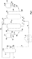
Figure 1 : illustrates one process scheme of present invention; -
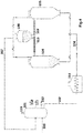
Figure2 : illustrates second process scheme of present invention; -
Figure 3 : illustrates process for co-conversion of waste plastic in delayed coker unit in accordance with another feature of the invention; -
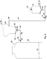
Figure 4 : illustrates process for co-conversion of waste plastic in delayed coker unit in accordance with another feature of the invention; and -
Figure 5 : illustrates process for co-conversion of waste plastic in delayed coker unit in accordance with another feature of the invention. - Accordingly, present invention relates to a process to convert low value plastic waste material into higher value lighter distillate products like Fuel gas, LPG, naphtha, Light Coker Gasoil (LCGO), Heavy Coker Gasoil (HCGO) and Coker Fuel Oil (CFO) etc. along with solid petroleum coke by thermally cracking the same in a Delayed Coker unit along with hydrocarbon feedstock.
- In detail, the invented process employs a unique process hardware scheme to feed the waste plastic into the coke drums directly without impacting the operation of other critical hardware like Furnace, which is susceptible to fouling, if there is impurities like metals, particles etc. in the feedstock being heated. The crushed waste plastic material is loaded into a fluidized feeder vessel and is supplied pneumatically to the coke drums through pneumatic conveying mechanism after the drum heating step is completed. Inside the coke drum, it undergoes co-conversion along with the hot petroleum residue stream which is being supplied from the bottom of the coke drum.
- Lighter distillates generated while thermal co-conversion in the vapor form inside the coke drum gets mixed with product vapors generated from thermal cracking of hydrocarbon feedstock and the combined product vapor is then routed to the main fractionator column to separate into desired liquid product fractions like light coke gasoil, heavy coke gasoil and coke fuel oil. The off-gases from the fractionator column overhead section are routed to the GASCON section for separation of naphtha, Fuel gas and LPG. The residue coke materials produced during the conversion of waste plastic will be deposited along with solid petroleum coke formed inside the coke drum due to thermal cracking of hydrocarbon feedstock. The metals in the waste plastics are mostly not in organo-metallic form and therefore are deposited preferentially in solid petroleum coke inside coke drum.
- The liquid hydrocarbon feedstock to be used in the process is selected from heavy hydrocarbon feedstocks like reduced crude oil, vacuum residue, atmospheric residue, deasphalted pitch, shale oil, coal tar, clarified oil, residual oils, heavy waxy distillates, foots oil, slop oil or blends of such hydrocarbons. The Conradson carbon residue content of the feedstock is above 3wt% and minimum density of 0.95 g/cc.
- Plastics are macromolecules, formed by polymerization and having the ability to be shaped by application of reasonable amount of heat and pressure or another form of forces. Plastic is a generic term for a wide range of polymers produced using highly refined fractions of crude oil, or chemicals derived from crude oil, known as monomers. Polymers are formed by the reaction of these monomers, which results in chain lengths of tens or hundreds of thousands of carbon atoms. Some polymers also contain oxygen (e.g. polyethylene terephthalate (PET)), whereas others contain chlorine (polyvinyl chloride (PVC)). Due to its non-biodegradable nature, the
plastic waste contributes significantly to the problem of waste management. - Plastics, depending upon their physical properties may be classified into thermoplastic or thermosetting plastic materials.
- Thermoplastic materials (Recyclable Plastics): These can be formed into desired shapes under heat and pressure and become solids on heating. Examples are Polythene, Polystyrene and PVC
- Thermostats or Thermosetting materials (Non-Recyclable Plastics): These, once shaped, cannot be softened/remolded by the application of heat. Examples are phenol formaldehyde and urea formaldehyde.
- In one feature of the present invention, the waste plastics are supplied from the plastic feeder vessel to the coke drum by using a conveyer such as screw conveyer.
- In another feature of the present invention, the waste plastic material is kept in the plastic feeder vessel in the molten form by application of heat and is supplied to the coke drum in liquid form.
In yet another feature of the invention, the waste plastics used for processing in the process of present invention can be in crushed form or as lumps which can be transported through other means like conveyer belts. - Reactor drums in the thermal cracking section of the process may be operated at a higher severity with desired operating temperature ranging from 470 to 520 °C, preferably between 480°C to 500 °C and desired operating pressure ranging from 0.5 to 5 Kg/cm2 (g) preferably between 0.6 to 3 Kg/cm2 (g). The cycle time of the coking and decoking cycles of the coke drums are kept more than 10 hr. The waste plastic material can be fed to the coke drum such as the percentage of waste plastic in comparison with the hydrocarbon feedstock supplied is in the range of 0.01 to 50 wt% preferably between 0.5 to 10 wt%.
- The process of the present invention is exemplified by, but not limited to
Fig 1 . In the process described inFig. 1 , the hydrocarbon feed (40) from the refinery enters the bottom of the main fractionator column (41) and is mixed with the internal recycle fraction to make the secondary feed (42). The secondary feed is then heated in a furnace (43) to the desired temperature. The hot feed (44) is then sent to a Delayed Coker drum (49, 48) whichever is in the hydrocarbon feeding cycle, through operation of appropriate valves (45, 46, and 47). Meanwhile, the waste plastic material from a fluidized plastic supply vessel (52) is pneumatically sent to the coke drum under feeding cycle. The hot residue feed is mixed with the waste plastic material supplied in the coke drum and thermal conversion happens for the residue feedstock as well as the waste plastic material. The plastic material is thermally decomposed into lighter molecules. The waste plastics in the supply vessel (52) are kept in fluidized condition by supply of fluidizing medium like air (54) sent through a distributor (53). The flow of plastic material through the standpipes (69, 59) is controlled by control valves (68, 56) which can be rotary airlock valves. Depending upon to which drum the plastic material is to be sent, the valves (68, 69, 62, 59) are operated. To assist in pneumatic conveying, fluid transport media (60, 57) are provided in the lift lines (58, 61) for waste plastics. The product vapors (63) from the coke drums are routed to the main fractionator column (41) for separation into different product fractions like Light Coker Gasoil (66), Heavy Coker Gasoil (65), and Coker Fuel Oil (64). The vapor fraction (67) is sent to the Gas concentration and separation section for separation of fuel gas, LPG and naphtha. - The embodiment of the process of the present invention is exemplified by, but not limited to
Fig 2 . In the process described inFig. 2 , the hydrocarbon feed (1) from the refinery enters the bottom of the main fractionator column (2) and is mixed with the internal recycle fraction to make the secondary feed (3). The secondary feed is then heated in a furnace (4) to the desired temperature. The hot feed (5) is then sent to a Delayed Coker drum (9, 10) whichever is in the hydrocarbon feeding cycle, through operation of appropriate valves (6, 7, 8) which can be rotary airlock valves. Meanwhile, the waste plastic material from a fluidized plastic supply vessel (13, 22) is pneumatically sent to the coke drum under feeding cycle. The hot residue feed is mixed with the waste plastic material supplied in the coke drum and thermal conversion happens for the residue feedstock as well as the waste plastic material. The plastic material is thermally decomposed into lighter molecules. The waste plastics in the supply vessels (13, 22) are kept in fluidized condition by supply of fluidizing medium like air (15, 24) sent through a distributor (14, 23). The flows of plastic material through the standpipes (16, 27) are controlled by control valves (17, 26) which can be rotary airlock valves. Depending upon to which drum the plastic material is to be sent, the valves (17, 20, 26, 30) are operated. To assist in pneumatic conveying, fluid transport media (18, 28) are provided in the lift lines (19, 29) for waste plastics. The product vapors (21) from the coke drums are routed to the main fractionator column (2) for separation into different product fractions like Light Coker Gasoil (31), Heavy Coker Gasoil (32) and Coker Fuel Oil (33). The vapor fraction (35) is sent to the Gas concentration and separation section for separation of fuel gas, LPG and naphtha. - One embodiment of the invention depicting plastic processing hardware and process is provided in
Fig.3 . In the process and hardware section descripted in said figure, the waste plastic granules are unloaded into the unloading vessel (71) through a hopper (70), inside which a rousing gas (72) is supplied through a header (73). The plastic is withdrawn at a controlled rate through the rotary airlock valve (74) and is pushed by a conveying gas (75) through a horizontal conveying line (76) which then moves vertically (79) to convey the plastic granules into the supply vessel (81) located at a higher elevation compared to the unloading vessel (71). Isolation valve (77) and purges (78, 80) are provided in the conveying gas line for additional purging and transport. Inside which a rousing gas (72) is supplied through a header (73). The supply vessel (81) is kept under controlled pressure through PCV (89). The plastic is withdrawn from the supply vessel (81) at a controlled rate through the rotary airlock valve (84) and is pushed by a conveying gas (85) through a horizontal conveying line (86) to convey the plastic granules into the coke drum (90). Purge flows (87) can be provided in the conveying line and isolation valve (88) in the conveying line. The waste plastic granules fall into the hot liquid pool (91) where it cracks into lighter products and the product vapor goes out through the vapor line (92). - In another embodiment of invention depicting the plastic processing hardware and process is provided in
Fig.4 . In the process and hardware section descripted in said figure, the waste plastic will be carried into the plastic supply vessel (108) in granule or crushed form from where, the plastic is carried into the heated screw conveyers (109, 113) wherein the plastic particles are melted and supplied into the coke drums (105, 106) which is in feeding cycle. The fresh feed (100) is supplied into the fractionator column (101) and the secondary feed (102) is withdrawn and is routed through the Furnace (103) to get the hot feed (104). The hot feed is then routed to the coke drums (105, 106) whichever is in the feeding cycle. Inside the coke drum in the feeding cycle, both the hydrocarbon hot feed as well as the plastic supplied through screw conveying mixes and the waste plastic gets thermally cracked into lighter hydrocarbon molecules. The product vapors are routed through overhead product vapor line (107) to the fractionator column (101) where the products are separated into off-gas with unstabilized naphtha (113), LCGO (110), HCGO (111) and CFO (112). Coke deposited inside the coke drums are removed by cutting using high pressure water jets after opening of flange in maintenance cycle. - In yet another embodiment of the invention depicting plastic processing hardware and process is provided in
Fig.5 . In the process and hardware section descripted in said figure, the waste plastic is loaded into the plastic supply vessel (207) wherein the plastic supplied (209) into the vessel is heated using a heating source (208) which can be either electrical or by a hot stream like superheated steam. The plastic supply (209) may be also mixed with a diluent stream for facilitating easy melting and transport. The molten liquid or slurry is pumped using a pump (210) and strained by using strainers (211) before supplying into the coke drums (205, 206) through a supply line (219). Isolation valves (212, 213) are provided in the plastic supply lines. The fresh feed (200) is supplied into the fractionator column (201) and the secondary feed (202) is withdrawn and is routed through the Furnace (203) to get the hot feed (204). The hot feed is then routed to the coke drums (205, 206) whichever is in the feeding cycle. Inside the coke drum in the feeding cycle, both the hydrocarbon hot feed as well as the plastic supplied through screw conveying mixes and the waste plastic gets thermally cracked into lighter hydrocarbon molecules. The product vapors are routed through overhead product vapor line (214) to the fractionator column (201) where the products are separated into off-gas with unstabilized naphtha (215), LCGO (216), HCGO (217) and CFO (218). Coke deposited inside the coke drums are removed by cutting using high pressure water jets after opening of flange in maintenance cycle. - The process of present invention is exemplified by following non-limiting examples.
- Vaccum reside feedstock was arranged from petroleum refinery and characterization was carried out. The properties of the vacuum residue feedstock are provided in Table-1.
Table-1: Properties of vacuum residue feedstock Property Value Density @ 15°C, g/cc 1.031 CCR, wt% 22.44 Asphaltene, wt% 8.52 Sulfur, wt% 4.40 Distillation (ASTM D2887) 10/20/50 432/ 538/ 594 - Experiments conducted in Micro-Coker unit with waste granules of LDPE (Low Low Density Polyethylene), HDPE (High Density Polyethylene), Mix Plastic and the vacuum residue. The mixing of the waste plastics and the vacuum residue feedstock was inside the Micro-Coker reactor. The operating conditions of the reaction section maintained for the experiments are provided in Table-2.
Table-2: Operating conditions of Micro-Coker reactor unit Operating Conditions Value Temperature, °C 486-488 Pressure, Kg/cm2g 1.8-2.1 - The product yields obtained in different experiments by co-processing of plastics with vacuum residue are provided in Table-3.
Table-3: Product yield data from experiments VR VR + LDPE VR + HDPE VR + Mixed Waste Run Number 1 2 3 4 5 6 7 8 9 10 Waste plastic dosing, wt% 0 10 20 40 10 20 40 10 20 40 Gas yield, wt% 21.5 16.06 17.11 12 18.12 19.29 28.46 18.26 15. 31 25. 86 Liquid yield, wt% 44.3 54.89 58.1 68.6 56.38 55.11 54.03 57.56 62. 55 56. 46 Coke yield, wt% 34.2 29.04 24.78 19.4 25.49 25.59 17.5 24.16 22. 12 17. 66 - It can be seen from the experimental data provided in Table-3 that the waste plastics have converted to gaseous and liquid fractions while co-processing.
- Further, experiments were carried out using vacuum residue feedstock of Table-1 and multilayer metal additized waste plastic granules with properties provided in Table-4, in a Delayed Coker pilot plant of 1 barrel per day capacity.
Table-4: Properties of multilayer metal additizedwaste plastic granule Composition Mix of PE, PP, PET (multilayer) Form Granules of cylindrical shape Size, mm 2 Bulk density, Kg/m3 507 Particle density, Kg/m3 923 Melting temperature, °C 122 °C onwards Metal by ICAP, ppmw Al/Ca 601/2583 - Experimental conditions are provided in Table-5. Waste plastic granules are directly supplied to the Coke Drum bypassing the furnace, where it cracks to lighter hydrocarbon products.
Table-5: Operating conditions of DCU Pilot Plant experiments Operating Condition Value Feed rate, kg/ hr 8 Drum inlet temp, °C 486 Coke drum pressure, kg/cm2g 1.0 Recycle ratio 0 Waste plastic dosing, wt% 2.2 Cycle time, hrs 12 - Two experiments were carried out - with and without dosing of waste plastic to the Drum. The results of experiments are provided in Table-6. It can be seen that the additionally input waste plastic has converted to different product fractions as can be seen from the Kg/cycle of product formation from waste plastic.
Table-6: DCU Pilot Plant yields with Feed-1 & Waste plastic Product yields Without Waste plastic dosing With 2.2% waste plastic (additional) Δyields wt% wt% wt% Kg/cycle FG 5.5 5.43 -0.07 0.047 LPG 5.94 5.84 -0.1 0.027 Coker Naphtha 10.99 11.08 0.09 0.320 LCGO 29.28 29.53 0.25 0.864 HCGO 20.57 20.52 -0.05 0.385 CFO 1.02 1 -0.02 0.002 Coke 26.7 26.6 -0.1 0.466 - A comparison of coke properties are provided in Table-7.lt can be seen that the metal content in the waste plastic has deposited in the coke which is formed during the Delayed Coking reaction and therefore the ash content has increased. The liquid products are devoid of any additional metal due to waste plastic processing.
Table-7: Comparison of coke properties due to plastic processing Coke Property Base case (without plastic) With plastic processing (2 wt%) Sulfur, wt% 5.1 5.1 Volatile matter, wt% 9.68 9.71 Moisture Content, wt% 0.23 0.2 Ash content, wt% 0.28 0.46 Fixed Carbon, wt% 89.43 89.3 - The following are the technical advantages of the present invention over the prior art as disclosed above:
- uses an add-on hardware section in existing Delayed Coker unit hardware to enable direct feeding of waste plastics into the coke drum to convert the waste plastics into valuable lighter distillate products
- enables the refiner to process waste plastic without any need for reducing the hydrocarbon feed thruput through the Coker Furnace
- enables the refiner to generate value from the low cost waste plastics and also address the environmental concerns of waste plastic disposal
- ensures that there is no incremental coke deposition inside the Delayed Coker furnace due to processing of waste plastics including metal additized plastics
- residual metallic fraction of the metal additized plastics get deposited in the solid petroleum coke generated in the Delayed Coking process
Claims (14)
- A process for conversion of a waste plastic into lighter distillate products, the process comprising:a. sending a fresh hydrocarbon feedstock into the bottom section of a main fractionator column and drawing out a secondary hydrocarbon feed from the column after mixing with an internal recycle fraction;b. feeding the secondary hydrocarbon feed after heating in a furnace to a delayed cokerdrum;c. loading the waste plastic into a supply vessel;d. conveying the waste plastic from the supply vessel to the delayed coker drum and then thermal cracking a mixture of the secondary feed and the waste plastic to obtain a combined product vapor inside the coke drum;e. routing the combined product vapor to a main fractionator column to obtain a light coker gasoil, a heavy coker gasoil and a coke fuel oil along with a vapor fraction; andf. sending the vapor fraction to a gas concentration (GASCON section) and separation section for separating into fuel gas, LPG and naphtha.
- The process as claimed in claim 1, wherein the waste plastic transport from the waste plastic supply vessel to the coke drums is carried out by means selected from pneumatic transport, extrusion or melt injection or combination thereof.
- The process as claimed in claim 2, wherein the waste plastic is selected from the group consisting of polystyrene, polypropylene, polyethylene, PET including metal additized multilayer plastics or combination thereof.
- The process as claimed in claim 2, wherein the physical form of waste plastic is selected from the group consisting of granules, powder, crushed chunks, slurry, melt or combination thereof.
- The process as claimed in any of the preceding claims 1 to 4, wherein the percentage of waste plastic in comparison with the hydrocarbon feedstock is in the range of 0.01 to 50 wt%.
- The process as claimed in any of the preceding claims 1 to 5, wherein the hydrocarbon feedstock is selected from crude oil, vacuum residue, atmospheric residue, deasphalted pitch, shale oil, coal tar, clarified oil, residual oils, heavy waxy distillates, foots oil, slop oil or mixture thereof.
- The process as claimed in any of the preceding claims 1 to 6, wherein the conradson carbon residue content of the hydrocarbon feedstock is in the range of 3 to 30wt% and density in the range of 0.95 to 1.08 g/cc.
- The process as claimed in any of the preceding claims 1 to 7, wherein the conversion occurs at a temperature in the range of 470 ºC to 520 ºC and a pressure in the range of 0.5 to 5 Kg/cm2.
- The process as claimed in any of the preceding claims 1 to 8, wherein the secondary feed in step (ii) is heated at a temperature in the range of 470 to 520 ºC.
- An apparatus for conversion of a waste plastic into light distillate products, the system comprising:(a) a main fractionator column to• route a fresh hydrocarbon feed with an internal recycle fraction to obtain a secondary feed;(b) a furnace connected to the main fractionator column to• heat the secondary feed to obtain a hot feed;(c) a waste plastic supply vessel to• to supply a fluidized waste plastic material to a delayed cokerdrum;(d) the delayed coker drum connected to the furnace and to the waste plastic supply vessel to• receive the hot feed from the furnace;• receive the waste plastic material from the plastic supply vessel• thermal decomposition/cracking of mixture of the hot feed and the waste plastic material to obtain a combined product vapor; and• rout the combined product vapor to the to the main fractionator column to obtain light coker gasoil, heavy coker gasoil and coker fuel oil along with a vapor fraction, and(e) a gas concentration and separation section connected to the main fractionator column to separate the vapor fraction into• fuel gas, LPG and naphtha.
- The apparatus as claimed in claim 10, wherein the waste plastic supply vessel is located at higher elevation than coke drums to enable smooth flow of plastics to the coke drums.
- The apparatus as claimed in any of claims 10 or 11, wherein the waste plastic is conveyed into the waste plastic supply vessel from another unloading vessel located at lower elevation compared to the waste plastic supply vessel through pneumatic transport or through conveyer belts.
- The apparatus as claimed in any of the preceding claims 10 to 12, wherein the waste plastic from waste plastic supply vessel is conveyed to Coke Drums by means of either pneumatic transport, screw feeder, melt injection or combination of both
- The apparatus as claimed in any of the preceding claims 10 to 13, wherein the waste plastic supply vessel has facility fora) rousing gas injection and purging;b) heating and melting of waste plastic; orc) controlling supply rate of waste plastic by means of rotary airlock valve or pump.a) The apparatus as claimed in any of the preceding claims 10 to 14, wherein the waste plastic supply vessel is kept under pressure higher than the coke drums, controlled by means of pressure control valve, in the range of 0.1 to 1 Kg/cm2g.
Applications Claiming Priority (1)
| Application Number | Priority Date | Filing Date | Title |
|---|---|---|---|
| IN201921038366 | 2019-09-23 |
Publications (1)
| Publication Number | Publication Date |
|---|---|
| EP3795656A1 true EP3795656A1 (en) | 2021-03-24 |
Family
ID=72050717
Family Applications (1)
| Application Number | Title | Priority Date | Filing Date |
|---|---|---|---|
| EP20190674.0A Pending EP3795656A1 (en) | 2019-09-23 | 2020-08-12 | A process and apparatus for co-conversion of waste plastics in delayed coker unit |
Country Status (4)
| Country | Link |
|---|---|
| US (1) | US11421159B2 (en) |
| EP (1) | EP3795656A1 (en) |
| JP (1) | JP7079297B2 (en) |
| CN (1) | CN112538363B (en) |
Families Citing this family (8)
| Publication number | Priority date | Publication date | Assignee | Title |
|---|---|---|---|---|
| EP4284894A1 (en) | 2021-01-29 | 2023-12-06 | Dorf Ketal Chemicals (India) Private Limited | Additive composition for reducing coke and increasing distillate during pyrolysis of a feedstock, and method of use thereof |
| EP4296598A1 (en) | 2021-03-24 | 2023-12-27 | FUJIFILM Corporation | Heat treatment device and method for manufacturing heat treatment object |
| US11859132B2 (en) * | 2021-08-05 | 2024-01-02 | Indian Oil Corporation Limited | Process and an apparatus for conversion of waste plastic pyrolysis oil into valuable products |
| KR20230087004A (en) * | 2021-12-09 | 2023-06-16 | 한국에너지기술연구원 | Method for converting waste plastic into fuel or chemical raw material using hydrocarbon compounds |
| WO2023192455A1 (en) * | 2022-04-01 | 2023-10-05 | Chevron U.S.A. Inc. | Circular economy for plastic waste to polypropylene and base oil via refinery crude unit |
| WO2023192452A1 (en) * | 2022-04-01 | 2023-10-05 | Chevron U.S.A. Inc. | Circular economy for plastic waste to polyethylene and base oil via refinery crude unit |
| WO2023215703A1 (en) | 2022-05-04 | 2023-11-09 | Exxonmobil Chemical Patents Inc. | Co-processing plastic waste in cokers for jet fuel production |
| WO2024018346A1 (en) | 2022-07-20 | 2024-01-25 | Dorf Ketal Chemicals (India) Private Limited | Coke reducing additive composition and method of use thereof. |
Citations (6)
| Publication number | Priority date | Publication date | Assignee | Title |
|---|---|---|---|---|
| US4118281A (en) | 1977-04-15 | 1978-10-03 | Mobil Oil Corporation | Conversion of solid wastes to fuel coke and gasoline/light oil |
| JPH0680970A (en) * | 1992-09-02 | 1994-03-22 | Japan Energy Corp | Treatment of polymeric material |
| WO1995014069A1 (en) | 1993-11-18 | 1995-05-26 | Mobil Oil Corporation | Disposal of plastic waste material |
| CN101230284A (en) * | 2007-01-25 | 2008-07-30 | 华东理工大学 | Delayed coking treatment method for waste plastics and treatment device thereof |
| US20140197560A1 (en) * | 2011-09-14 | 2014-07-17 | Sgl Carbon Se | Production of carbon-fiber reinforced coke |
| US20180201847A1 (en) | 2017-01-16 | 2018-07-19 | Council Of Scientific And Industrial Research | Process for upgradation of heavy crude oil/residue using waste plastic as hydrogen donating agent |
Family Cites Families (2)
| Publication number | Priority date | Publication date | Assignee | Title |
|---|---|---|---|---|
| US20020179493A1 (en) * | 1999-08-20 | 2002-12-05 | Environmental & Energy Enterprises, Llc | Production and use of a premium fuel grade petroleum coke |
| JP4154929B2 (en) * | 2002-06-05 | 2008-09-24 | Jfeスチール株式会社 | Method for producing useful substances from plastic |
-
2020
- 2020-08-12 EP EP20190674.0A patent/EP3795656A1/en active Pending
- 2020-08-20 JP JP2020139364A patent/JP7079297B2/en active Active
- 2020-08-26 CN CN202010868490.2A patent/CN112538363B/en active Active
- 2020-08-27 US US17/005,184 patent/US11421159B2/en active Active
Patent Citations (6)
| Publication number | Priority date | Publication date | Assignee | Title |
|---|---|---|---|---|
| US4118281A (en) | 1977-04-15 | 1978-10-03 | Mobil Oil Corporation | Conversion of solid wastes to fuel coke and gasoline/light oil |
| JPH0680970A (en) * | 1992-09-02 | 1994-03-22 | Japan Energy Corp | Treatment of polymeric material |
| WO1995014069A1 (en) | 1993-11-18 | 1995-05-26 | Mobil Oil Corporation | Disposal of plastic waste material |
| CN101230284A (en) * | 2007-01-25 | 2008-07-30 | 华东理工大学 | Delayed coking treatment method for waste plastics and treatment device thereof |
| US20140197560A1 (en) * | 2011-09-14 | 2014-07-17 | Sgl Carbon Se | Production of carbon-fiber reinforced coke |
| US20180201847A1 (en) | 2017-01-16 | 2018-07-19 | Council Of Scientific And Industrial Research | Process for upgradation of heavy crude oil/residue using waste plastic as hydrogen donating agent |
Non-Patent Citations (1)
| Title |
|---|
| "TIRE FED COKING UNIT", RESEARCH DISCLOSURE, KENNETH MASON PUBLICATIONS, HAMPSHIRE, UK, GB, no. 448, 1 August 2001 (2001-08-01), pages 1365 - 1367, XP001128212, ISSN: 0374-4353 * |
Also Published As
| Publication number | Publication date |
|---|---|
| US11421159B2 (en) | 2022-08-23 |
| CN112538363B (en) | 2022-10-21 |
| JP7079297B2 (en) | 2022-06-01 |
| JP2021050325A (en) | 2021-04-01 |
| US20210087473A1 (en) | 2021-03-25 |
| CN112538363A (en) | 2021-03-23 |
Similar Documents
| Publication | Publication Date | Title |
|---|---|---|
| EP3795656A1 (en) | A process and apparatus for co-conversion of waste plastics in delayed coker unit | |
| EP3950889A1 (en) | Process for co-conversion of waste plastics and hydrocarbon feedstock | |
| US10093864B2 (en) | Method and apparatus for continuous recycling of waste plastic into liquid fuels | |
| KR100294809B1 (en) | Recycling method of plastic in steam cracker | |
| KR101902307B1 (en) | Method and apparatus for energy-efficient processing of secondary deposits | |
| EP3328967B1 (en) | Integrated enhanced solvent deasphalting and coking process to produce petroleum green coke | |
| US5917102A (en) | Device for depolymerizing used and waste plastics | |
| AU2009267795B2 (en) | Method of processing oil refining waste | |
| BG62572B1 (en) | Method for the recycling of secondary or waste plastics | |
| EP2336274A1 (en) | Use of upgraded heavy hydrocarbon feedstocks in pipelines | |
| CN114829545A (en) | Co-processing of plastic waste in a coker | |
| US20120125815A1 (en) | Rapid thermal processing of heavy hydrocarbon feedstocks | |
| WO2021216284A1 (en) | Fluidized bed plastic waste pyrolysis with melt extruder | |
| WO2023111946A1 (en) | Methods and systems for conversion of mixed plastics to high value chemicals | |
| US20230331991A1 (en) | Method for solvolysing tyres with recycling of a hydrocarbon fraction comprising aromatic compounds | |
| CA3008103A1 (en) | Processes and apparatus to produce solid asphaltene products from hydrocarbon feedstocks | |
| CN116064064A (en) | Method and system for recycling waste plastics through pyrolysis | |
| CN115989300A (en) | Pyrolysis of plastic waste using liquid recycling | |
| US20230332051A1 (en) | Integrated mixed plastic pyrolysis with heavy oil product thermal cracking | |
| EP4130199A1 (en) | Process for cracking a polyolefin containing material | |
| US20240093102A1 (en) | Integration of Polymeric Waste Co-Processing in Cokers to Produce Circular Chemical Products from Coker Gas Oil | |
| Sau et al. | Co-Conversion of Waste Plastic to Light Distillates in Delayed Coking Process | |
| CN116064071A (en) | Method and system for treating chlorine-containing waste plastics by using delayed coking device | |
| WO2023279019A1 (en) | Systems and methods for processing mixed plastic waste | |
| WO2023114881A1 (en) | Systems and methods to upgrade a hydrocarbon stream to a lower boiling point feed material |
Legal Events
| Date | Code | Title | Description |
|---|---|---|---|
| PUAI | Public reference made under article 153(3) epc to a published international application that has entered the european phase |
Free format text: ORIGINAL CODE: 0009012 |
|
| STAA | Information on the status of an ep patent application or granted ep patent |
Free format text: STATUS: REQUEST FOR EXAMINATION WAS MADE |
|
| 17P | Request for examination filed |
Effective date: 20200812 |
|
| AK | Designated contracting states |
Kind code of ref document: A1 Designated state(s): AL AT BE BG CH CY CZ DE DK EE ES FI FR GB GR HR HU IE IS IT LI LT LU LV MC MK MT NL NO PL PT RO RS SE SI SK SM TR |
|
| AX | Request for extension of the european patent |
Extension state: BA ME |
|
| P01 | Opt-out of the competence of the unified patent court (upc) registered |
Effective date: 20230712 |