EP3795537A1 - Catalytic fixed-bed reactor including an electric heating element, unit for producing hydrogen by steam reforming comprising such a reactor and an electric steam generator, associated operating method - Google Patents
Catalytic fixed-bed reactor including an electric heating element, unit for producing hydrogen by steam reforming comprising such a reactor and an electric steam generator, associated operating method Download PDFInfo
- Publication number
- EP3795537A1 EP3795537A1 EP20196875.7A EP20196875A EP3795537A1 EP 3795537 A1 EP3795537 A1 EP 3795537A1 EP 20196875 A EP20196875 A EP 20196875A EP 3795537 A1 EP3795537 A1 EP 3795537A1
- Authority
- EP
- European Patent Office
- Prior art keywords
- fixed bed
- reforming
- catalytic
- reactor
- catalytic fixed
- Prior art date
- Legal status (The legal status is an assumption and is not a legal conclusion. Google has not performed a legal analysis and makes no representation as to the accuracy of the status listed.)
- Granted
Links
- 239000001257 hydrogen Substances 0.000 title claims abstract description 60
- 229910052739 hydrogen Inorganic materials 0.000 title claims abstract description 60
- UFHFLCQGNIYNRP-UHFFFAOYSA-N Hydrogen Chemical compound [H][H] UFHFLCQGNIYNRP-UHFFFAOYSA-N 0.000 title claims abstract description 52
- 230000003197 catalytic effect Effects 0.000 title claims abstract description 46
- 238000000629 steam reforming Methods 0.000 title claims abstract description 44
- 238000005485 electric heating Methods 0.000 title claims abstract description 13
- 238000011017 operating method Methods 0.000 title claims 3
- VNWKTOKETHGBQD-UHFFFAOYSA-N methane Chemical compound C VNWKTOKETHGBQD-UHFFFAOYSA-N 0.000 claims abstract description 77
- 238000002407 reforming Methods 0.000 claims abstract description 50
- XLYOFNOQVPJJNP-UHFFFAOYSA-N water Chemical compound O XLYOFNOQVPJJNP-UHFFFAOYSA-N 0.000 claims abstract description 39
- 239000003345 natural gas Substances 0.000 claims abstract description 29
- 239000000203 mixture Substances 0.000 claims abstract description 12
- 238000009413 insulation Methods 0.000 claims abstract description 10
- 238000004519 manufacturing process Methods 0.000 claims description 50
- 239000007789 gas Substances 0.000 claims description 26
- 239000012528 membrane Substances 0.000 claims description 23
- 238000009826 distribution Methods 0.000 claims description 17
- 239000000919 ceramic Substances 0.000 claims description 9
- 150000002431 hydrogen Chemical class 0.000 claims description 8
- 238000011144 upstream manufacturing Methods 0.000 claims description 7
- PXHVJJICTQNCMI-UHFFFAOYSA-N Nickel Chemical compound [Ni] PXHVJJICTQNCMI-UHFFFAOYSA-N 0.000 claims description 6
- KDLHZDBZIXYQEI-UHFFFAOYSA-N Palladium Chemical compound [Pd] KDLHZDBZIXYQEI-UHFFFAOYSA-N 0.000 claims description 6
- VYPSYNLAJGMNEJ-UHFFFAOYSA-N Silicium dioxide Chemical compound O=[Si]=O VYPSYNLAJGMNEJ-UHFFFAOYSA-N 0.000 claims description 6
- 238000010438 heat treatment Methods 0.000 claims description 6
- 239000011248 coating agent Substances 0.000 claims description 3
- 238000000576 coating method Methods 0.000 claims description 3
- 239000000835 fiber Substances 0.000 claims description 3
- 239000002557 mineral fiber Substances 0.000 claims description 3
- 229910052759 nickel Inorganic materials 0.000 claims description 3
- 229910052763 palladium Inorganic materials 0.000 claims description 3
- 239000000377 silicon dioxide Substances 0.000 claims description 3
- 238000001991 steam methane reforming Methods 0.000 claims description 3
- 239000004753 textile Substances 0.000 claims description 3
- 229910052751 metal Inorganic materials 0.000 claims description 2
- 239000002184 metal Substances 0.000 claims description 2
- 239000008400 supply water Substances 0.000 claims description 2
- 229910000601 superalloy Inorganic materials 0.000 claims 1
- 238000006243 chemical reaction Methods 0.000 description 13
- 238000001179 sorption measurement Methods 0.000 description 12
- 238000000746 purification Methods 0.000 description 8
- 238000002485 combustion reaction Methods 0.000 description 7
- 238000009434 installation Methods 0.000 description 7
- 239000000463 material Substances 0.000 description 7
- 230000008901 benefit Effects 0.000 description 6
- 239000003054 catalyst Substances 0.000 description 6
- 230000006835 compression Effects 0.000 description 6
- 238000007906 compression Methods 0.000 description 6
- 230000005611 electricity Effects 0.000 description 6
- 238000005516 engineering process Methods 0.000 description 6
- 230000010354 integration Effects 0.000 description 6
- 238000010926 purge Methods 0.000 description 6
- 230000006872 improvement Effects 0.000 description 5
- 230000009467 reduction Effects 0.000 description 5
- 150000001412 amines Chemical class 0.000 description 4
- IJGRMHOSHXDMSA-UHFFFAOYSA-N Atomic nitrogen Chemical compound N#N IJGRMHOSHXDMSA-UHFFFAOYSA-N 0.000 description 3
- 229910002091 carbon monoxide Inorganic materials 0.000 description 3
- 238000006477 desulfuration reaction Methods 0.000 description 3
- 230000023556 desulfurization Effects 0.000 description 3
- 230000000694 effects Effects 0.000 description 3
- 238000005868 electrolysis reaction Methods 0.000 description 3
- 238000000034 method Methods 0.000 description 3
- 238000011084 recovery Methods 0.000 description 3
- 238000006057 reforming reaction Methods 0.000 description 3
- 241000861223 Issus Species 0.000 description 2
- 230000006978 adaptation Effects 0.000 description 2
- 229910045601 alloy Inorganic materials 0.000 description 2
- 239000000956 alloy Substances 0.000 description 2
- 230000009286 beneficial effect Effects 0.000 description 2
- 230000005540 biological transmission Effects 0.000 description 2
- 230000003750 conditioning effect Effects 0.000 description 2
- 238000005265 energy consumption Methods 0.000 description 2
- 238000000605 extraction Methods 0.000 description 2
- 230000004907 flux Effects 0.000 description 2
- 229910001026 inconel Inorganic materials 0.000 description 2
- 239000012212 insulator Substances 0.000 description 2
- 210000000056 organ Anatomy 0.000 description 2
- 230000008569 process Effects 0.000 description 2
- 230000001105 regulatory effect Effects 0.000 description 2
- 238000004513 sizing Methods 0.000 description 2
- 239000002028 Biomass Substances 0.000 description 1
- UGFAIRIUMAVXCW-UHFFFAOYSA-N Carbon monoxide Chemical compound [O+]#[C-] UGFAIRIUMAVXCW-UHFFFAOYSA-N 0.000 description 1
- YZCKVEUIGOORGS-IGMARMGPSA-N Protium Chemical compound [1H] YZCKVEUIGOORGS-IGMARMGPSA-N 0.000 description 1
- 229910000831 Steel Inorganic materials 0.000 description 1
- 240000008042 Zea mays Species 0.000 description 1
- 229940112112 capex Drugs 0.000 description 1
- 229910052799 carbon Inorganic materials 0.000 description 1
- 238000006555 catalytic reaction Methods 0.000 description 1
- 238000001193 catalytic steam reforming Methods 0.000 description 1
- 210000004027 cell Anatomy 0.000 description 1
- 239000000567 combustion gas Substances 0.000 description 1
- 230000001143 conditioned effect Effects 0.000 description 1
- 238000001816 cooling Methods 0.000 description 1
- 230000029087 digestion Effects 0.000 description 1
- 230000008034 disappearance Effects 0.000 description 1
- 230000008030 elimination Effects 0.000 description 1
- 238000003379 elimination reaction Methods 0.000 description 1
- 229940082150 encore Drugs 0.000 description 1
- 239000003344 environmental pollutant Substances 0.000 description 1
- FEBLZLNTKCEFIT-VSXGLTOVSA-N fluocinolone acetonide Chemical compound C1([C@@H](F)C2)=CC(=O)C=C[C@]1(C)[C@]1(F)[C@@H]2[C@@H]2C[C@H]3OC(C)(C)O[C@@]3(C(=O)CO)[C@@]2(C)C[C@@H]1O FEBLZLNTKCEFIT-VSXGLTOVSA-N 0.000 description 1
- 239000000446 fuel Substances 0.000 description 1
- 239000003517 fume Substances 0.000 description 1
- 239000005431 greenhouse gas Substances 0.000 description 1
- 238000002513 implantation Methods 0.000 description 1
- 238000002955 isolation Methods 0.000 description 1
- 230000004807 localization Effects 0.000 description 1
- 229910052757 nitrogen Inorganic materials 0.000 description 1
- 231100000719 pollutant Toxicity 0.000 description 1
- 238000000926 separation method Methods 0.000 description 1
- 241000894007 species Species 0.000 description 1
- 239000010959 steel Substances 0.000 description 1
- 238000003860 storage Methods 0.000 description 1
- 230000001629 suppression Effects 0.000 description 1
- 239000002699 waste material Substances 0.000 description 1
Images


Classifications
-
- C—CHEMISTRY; METALLURGY
- C01—INORGANIC CHEMISTRY
- C01B—NON-METALLIC ELEMENTS; COMPOUNDS THEREOF; METALLOIDS OR COMPOUNDS THEREOF NOT COVERED BY SUBCLASS C01C
- C01B3/00—Hydrogen; Gaseous mixtures containing hydrogen; Separation of hydrogen from mixtures containing it; Purification of hydrogen
- C01B3/02—Production of hydrogen or of gaseous mixtures containing a substantial proportion of hydrogen
- C01B3/32—Production of hydrogen or of gaseous mixtures containing a substantial proportion of hydrogen by reaction of gaseous or liquid organic compounds with gasifying agents, e.g. water, carbon dioxide, air
- C01B3/34—Production of hydrogen or of gaseous mixtures containing a substantial proportion of hydrogen by reaction of gaseous or liquid organic compounds with gasifying agents, e.g. water, carbon dioxide, air by reaction of hydrocarbons with gasifying agents
- C01B3/38—Production of hydrogen or of gaseous mixtures containing a substantial proportion of hydrogen by reaction of gaseous or liquid organic compounds with gasifying agents, e.g. water, carbon dioxide, air by reaction of hydrocarbons with gasifying agents using catalysts
-
- B—PERFORMING OPERATIONS; TRANSPORTING
- B01—PHYSICAL OR CHEMICAL PROCESSES OR APPARATUS IN GENERAL
- B01J—CHEMICAL OR PHYSICAL PROCESSES, e.g. CATALYSIS OR COLLOID CHEMISTRY; THEIR RELEVANT APPARATUS
- B01J19/00—Chemical, physical or physico-chemical processes in general; Their relevant apparatus
- B01J19/24—Stationary reactors without moving elements inside
- B01J19/2475—Membrane reactors
-
- B—PERFORMING OPERATIONS; TRANSPORTING
- B01—PHYSICAL OR CHEMICAL PROCESSES OR APPARATUS IN GENERAL
- B01J—CHEMICAL OR PHYSICAL PROCESSES, e.g. CATALYSIS OR COLLOID CHEMISTRY; THEIR RELEVANT APPARATUS
- B01J8/00—Chemical or physical processes in general, conducted in the presence of fluids and solid particles; Apparatus for such processes
- B01J8/008—Details of the reactor or of the particulate material; Processes to increase or to retard the rate of reaction
- B01J8/009—Membranes, e.g. feeding or removing reactants or products to or from the catalyst bed through a membrane
-
- B—PERFORMING OPERATIONS; TRANSPORTING
- B01—PHYSICAL OR CHEMICAL PROCESSES OR APPARATUS IN GENERAL
- B01J—CHEMICAL OR PHYSICAL PROCESSES, e.g. CATALYSIS OR COLLOID CHEMISTRY; THEIR RELEVANT APPARATUS
- B01J8/00—Chemical or physical processes in general, conducted in the presence of fluids and solid particles; Apparatus for such processes
- B01J8/02—Chemical or physical processes in general, conducted in the presence of fluids and solid particles; Apparatus for such processes with stationary particles, e.g. in fixed beds
- B01J8/0207—Chemical or physical processes in general, conducted in the presence of fluids and solid particles; Apparatus for such processes with stationary particles, e.g. in fixed beds the fluid flow within the bed being predominantly horizontal
- B01J8/0214—Chemical or physical processes in general, conducted in the presence of fluids and solid particles; Apparatus for such processes with stationary particles, e.g. in fixed beds the fluid flow within the bed being predominantly horizontal in a cylindrical annular shaped bed
-
- B—PERFORMING OPERATIONS; TRANSPORTING
- B01—PHYSICAL OR CHEMICAL PROCESSES OR APPARATUS IN GENERAL
- B01J—CHEMICAL OR PHYSICAL PROCESSES, e.g. CATALYSIS OR COLLOID CHEMISTRY; THEIR RELEVANT APPARATUS
- B01J8/00—Chemical or physical processes in general, conducted in the presence of fluids and solid particles; Apparatus for such processes
- B01J8/02—Chemical or physical processes in general, conducted in the presence of fluids and solid particles; Apparatus for such processes with stationary particles, e.g. in fixed beds
- B01J8/0242—Chemical or physical processes in general, conducted in the presence of fluids and solid particles; Apparatus for such processes with stationary particles, e.g. in fixed beds the fluid flow within the bed being predominantly vertical
- B01J8/0257—Chemical or physical processes in general, conducted in the presence of fluids and solid particles; Apparatus for such processes with stationary particles, e.g. in fixed beds the fluid flow within the bed being predominantly vertical in a cylindrical annular shaped bed
-
- B—PERFORMING OPERATIONS; TRANSPORTING
- B01—PHYSICAL OR CHEMICAL PROCESSES OR APPARATUS IN GENERAL
- B01J—CHEMICAL OR PHYSICAL PROCESSES, e.g. CATALYSIS OR COLLOID CHEMISTRY; THEIR RELEVANT APPARATUS
- B01J8/00—Chemical or physical processes in general, conducted in the presence of fluids and solid particles; Apparatus for such processes
- B01J8/02—Chemical or physical processes in general, conducted in the presence of fluids and solid particles; Apparatus for such processes with stationary particles, e.g. in fixed beds
- B01J8/0285—Heating or cooling the reactor
-
- B—PERFORMING OPERATIONS; TRANSPORTING
- B01—PHYSICAL OR CHEMICAL PROCESSES OR APPARATUS IN GENERAL
- B01J—CHEMICAL OR PHYSICAL PROCESSES, e.g. CATALYSIS OR COLLOID CHEMISTRY; THEIR RELEVANT APPARATUS
- B01J8/00—Chemical or physical processes in general, conducted in the presence of fluids and solid particles; Apparatus for such processes
- B01J8/02—Chemical or physical processes in general, conducted in the presence of fluids and solid particles; Apparatus for such processes with stationary particles, e.g. in fixed beds
- B01J8/06—Chemical or physical processes in general, conducted in the presence of fluids and solid particles; Apparatus for such processes with stationary particles, e.g. in fixed beds in tube reactors; the solid particles being arranged in tubes
- B01J8/062—Chemical or physical processes in general, conducted in the presence of fluids and solid particles; Apparatus for such processes with stationary particles, e.g. in fixed beds in tube reactors; the solid particles being arranged in tubes being installed in a furnace
-
- C—CHEMISTRY; METALLURGY
- C01—INORGANIC CHEMISTRY
- C01B—NON-METALLIC ELEMENTS; COMPOUNDS THEREOF; METALLOIDS OR COMPOUNDS THEREOF NOT COVERED BY SUBCLASS C01C
- C01B3/00—Hydrogen; Gaseous mixtures containing hydrogen; Separation of hydrogen from mixtures containing it; Purification of hydrogen
- C01B3/50—Separation of hydrogen or hydrogen containing gases from gaseous mixtures, e.g. purification
- C01B3/501—Separation of hydrogen or hydrogen containing gases from gaseous mixtures, e.g. purification by diffusion
-
- B—PERFORMING OPERATIONS; TRANSPORTING
- B01—PHYSICAL OR CHEMICAL PROCESSES OR APPARATUS IN GENERAL
- B01J—CHEMICAL OR PHYSICAL PROCESSES, e.g. CATALYSIS OR COLLOID CHEMISTRY; THEIR RELEVANT APPARATUS
- B01J2208/00—Processes carried out in the presence of solid particles; Reactors therefor
- B01J2208/00008—Controlling the process
- B01J2208/00017—Controlling the temperature
- B01J2208/00106—Controlling the temperature by indirect heat exchange
- B01J2208/00168—Controlling the temperature by indirect heat exchange with heat exchange elements outside the bed of solid particles
- B01J2208/00203—Coils
-
- B—PERFORMING OPERATIONS; TRANSPORTING
- B01—PHYSICAL OR CHEMICAL PROCESSES OR APPARATUS IN GENERAL
- B01J—CHEMICAL OR PHYSICAL PROCESSES, e.g. CATALYSIS OR COLLOID CHEMISTRY; THEIR RELEVANT APPARATUS
- B01J2208/00—Processes carried out in the presence of solid particles; Reactors therefor
- B01J2208/00008—Controlling the process
- B01J2208/00017—Controlling the temperature
- B01J2208/00389—Controlling the temperature using electric heating or cooling elements
- B01J2208/00407—Controlling the temperature using electric heating or cooling elements outside the reactor bed
-
- B—PERFORMING OPERATIONS; TRANSPORTING
- B01—PHYSICAL OR CHEMICAL PROCESSES OR APPARATUS IN GENERAL
- B01J—CHEMICAL OR PHYSICAL PROCESSES, e.g. CATALYSIS OR COLLOID CHEMISTRY; THEIR RELEVANT APPARATUS
- B01J2208/00—Processes carried out in the presence of solid particles; Reactors therefor
- B01J2208/00008—Controlling the process
- B01J2208/00017—Controlling the temperature
- B01J2208/00389—Controlling the temperature using electric heating or cooling elements
- B01J2208/00415—Controlling the temperature using electric heating or cooling elements electric resistance heaters
-
- B—PERFORMING OPERATIONS; TRANSPORTING
- B01—PHYSICAL OR CHEMICAL PROCESSES OR APPARATUS IN GENERAL
- B01J—CHEMICAL OR PHYSICAL PROCESSES, e.g. CATALYSIS OR COLLOID CHEMISTRY; THEIR RELEVANT APPARATUS
- B01J2208/00—Processes carried out in the presence of solid particles; Reactors therefor
- B01J2208/00008—Controlling the process
- B01J2208/00017—Controlling the temperature
- B01J2208/00477—Controlling the temperature by thermal insulation means
- B01J2208/00495—Controlling the temperature by thermal insulation means using insulating materials or refractories
-
- C—CHEMISTRY; METALLURGY
- C01—INORGANIC CHEMISTRY
- C01B—NON-METALLIC ELEMENTS; COMPOUNDS THEREOF; METALLOIDS OR COMPOUNDS THEREOF NOT COVERED BY SUBCLASS C01C
- C01B2203/00—Integrated processes for the production of hydrogen or synthesis gas
- C01B2203/02—Processes for making hydrogen or synthesis gas
- C01B2203/0205—Processes for making hydrogen or synthesis gas containing a reforming step
- C01B2203/0227—Processes for making hydrogen or synthesis gas containing a reforming step containing a catalytic reforming step
- C01B2203/0233—Processes for making hydrogen or synthesis gas containing a reforming step containing a catalytic reforming step the reforming step being a steam reforming step
-
- C—CHEMISTRY; METALLURGY
- C01—INORGANIC CHEMISTRY
- C01B—NON-METALLIC ELEMENTS; COMPOUNDS THEREOF; METALLOIDS OR COMPOUNDS THEREOF NOT COVERED BY SUBCLASS C01C
- C01B2203/00—Integrated processes for the production of hydrogen or synthesis gas
- C01B2203/04—Integrated processes for the production of hydrogen or synthesis gas containing a purification step for the hydrogen or the synthesis gas
- C01B2203/0405—Purification by membrane separation
- C01B2203/041—In-situ membrane purification during hydrogen production
-
- C—CHEMISTRY; METALLURGY
- C01—INORGANIC CHEMISTRY
- C01B—NON-METALLIC ELEMENTS; COMPOUNDS THEREOF; METALLOIDS OR COMPOUNDS THEREOF NOT COVERED BY SUBCLASS C01C
- C01B2203/00—Integrated processes for the production of hydrogen or synthesis gas
- C01B2203/08—Methods of heating or cooling
- C01B2203/0805—Methods of heating the process for making hydrogen or synthesis gas
- C01B2203/085—Methods of heating the process for making hydrogen or synthesis gas by electric heating
-
- C—CHEMISTRY; METALLURGY
- C01—INORGANIC CHEMISTRY
- C01B—NON-METALLIC ELEMENTS; COMPOUNDS THEREOF; METALLOIDS OR COMPOUNDS THEREOF NOT COVERED BY SUBCLASS C01C
- C01B2203/00—Integrated processes for the production of hydrogen or synthesis gas
- C01B2203/12—Feeding the process for making hydrogen or synthesis gas
- C01B2203/1288—Evaporation of one or more of the different feed components
Definitions
- the present invention relates to the field of decentralized hydrogen production for the merchant hydrogen sector and the supply of hydrogen distribution stations.
- the invention relates firstly to the reactor for producing hydrogen by steam reforming and the decentralized unit for producing merchantable hydrogen or for the mobility which uses it.
- merchantable hydrogen is meant the hydrogen which is produced, and conditioned by an actor, in tubes on a truck trailer or in cylindrical bottles then transported over a significant distance and sold to a consumer other than producer, generally small consumers.
- the production of hydrogen requires material containing hydrogen (water, methane, etc.) and energy (heat, electricity) to extract hydrogen from the material.
- this material and this energy must be available locally either through a distribution network with a sufficiently fine mesh, or by local productions available near the place of production and therefore the need.
- the production envisaged locally ranges from a few kilograms to a few hundred kilograms per hour and the production unit must be located close to the consumer market (small industrial or service consumers, hydrogen stations for road and river mobility).
- this technology has a marginal production cost of hydrogen three to four times higher than that of gas (depending on the country), a capex (acronym for "capital expenditure” or investment) of installation higher than for a reforming unit, typically 2 to 3 times higher, if indeed they can be compared because the capacities of existing units are very different from those of current reforming, double water consumption, lower energy efficiency, typically from minus 5% to minus 20%, including at the unit level and CO 2 emissions which depend on the nature of the country's electricity mix. On this last point, in the United Kingdom, the emission is 400g CO 2 / kWh, which is very high.
- a unit for the production of hydrogen by steam reforming as envisaged from the 2010s is a complex system with several stations or functional stages, which tends to be as energy efficient as possible and to the lowest possible release of CO 2 at the stack. the atmosphere.
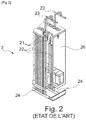
- the figure 1 shows a schematic representation of such a unit, generally designated by the reference 1, which also implements a capture and then conditioning of the CO 2 produced.
- Stage 2 comprises a furnace whose enclosure 20 houses a plurality of gas burners 21 in which are suspended tubes each forming a reforming reactor 22, which are heated by convection of the combustion gases and inside which a place the reforming of methane into syngas. These tubes 22 are filled with catalyst and fed at the top from inlet collectors 23 with a mixture of natural gas and water vapor. The produced syngas is extracted by outlet collectors 24.
- a reforming tube 22 with a catalyst 25 the arrows symbolizing the supply and the outlet of the gases.
- the temperature in the catalyst 25 must be at least 800 ° C, which requires much higher temperatures in the furnace chamber 20 and therefore external temperatures near the walls 26 of reforming tubes, in general more than 1000 ° C. This implies that the gas pressure which must prevail inside a reforming tube is less than around 20 bars, in order to guarantee the mechanical strength of the tube.
- the aim of the invention is to respond at least in part to this need.
- the catalytic fixed bed reactor is generally tubular in shape.
- the electric heating element is a tube based on inconel or a ceramic fiber or a heating metal wire molded directly into a ceramic.
- the thermal insulation element is formed by a textile consisting of layers of mineral fibers or silica felts or by an inorganic refractory coating.
- the reactor comprises at least one permselective membrane for hydrogen, arranged in the reforming chamber, at the periphery of the and / or inserted in the fixed catalytic bed, leaving a space between the membrane and the (the) wall (s) delimiting the chamber or the thermal insulation element, the space being suitable for the recovery of the hydrogen produced by steam reforming.
- the membrane is advantageously an inorganic membrane consisting of nickel or palladium deposited on a porous ceramic support.
- the membrane is preferably coaxial with the catalytic fixed bed.
- electric steam generator is meant here and in the context of the invention, a generator which uses electricity as a power source to produce heat which generates steam, instead of burning fuel. .
- the outlet of the reactor is fluidly connected to the natural gas distribution network.
- the unit comprises a return line connected between the outlet of the reactor and the natural gas network, in order to return the gas partially reformed in the reactor to the latter.
- a subject of the invention is a method of operating a unit for producing hydrogen by steam reforming as described above, according to which the mixture of gas and water vapor supplying the catalytic fixed bed reactor is at a pressure greater than or equal to 20 bars.
- the gas is preferably natural gas from the distribution network, the pressure of which is that of supplying the catalytic fixed bed reactor.
- the wall of the reforming / confinement chamber can therefore be cold, typically at a temperature below 400 ° C, and be thermally insulated from the hot catalytic reaction zone either by an added thermal insulator or by the catalyst bed itself. , which does not conduct much heat.
- the figures 1 to 3 relate to an example of a steam reforming stage and of a hydrogen production unit according to the state of the art. These figures 1 to 3 have already been commented on in the preamble and are therefore not commented on further below.
- It comprises a reforming chamber 22, of generally tubular shape, intended to be fed at the head with a mixture of natural gas or biogas and water vapor and in which is housed a fixed catalytic bed 25 of steam reforming with steam. 'water.
- an electric heating element 27 is inserted directly into the catalytic fixed bed to heat the latter.
- the electric heating element 27 may be an inconel-based tube or a ceramic fiber or a heating wire molded directly into a ceramic.
- a thermal insulation element 28 is arranged between the fixed catalytic bed 25 and the wall 26 delimiting the reforming chamber 22.
- This thermal insulator 28 makes it possible to confine the heat produced by the electric heating inside the heating chamber. reforming 22 and therefore to have a relatively cold wall 26, typically at a temperature below 400 ° C during the steam reforming reaction.
- the thermal insulation element 28 may consist of a textile consisting of layers of mineral fibers or of silica felts or of an inorganic refractory coating.
- FIG. 5 An advantageous embodiment of the catalytic fixed bed reactor 2 according to the invention is shown in figure 5 .
- a membrane 29 permselective to hydrogen is arranged in the reforming chamber 22, coaxially with the fixed catalytic bed 25, leaving a space between the membrane 29 and the thermal insulation element 28.
- This space allows to take part of the hydrogen produced by steam reforming. in the catalytic bed 25, with the advantage of counterbalancing the negative effect of the pressure on the conversion of methane. This advantage is clearly highlighted in figure 6 , which is taken from publication [1].
- the membrane 29 can be an inorganic membrane consisting of nickel or palladium deposited on a porous ceramic support.
- FIG. 7 a unit for producing hydrogen 1 by steam reforming which incorporates at least one stage for reforming methane with steam comprising a reactor 2 with a fixed catalytic bed according to the invention which has just been described.
- a unit 1 comprises an electric steam generator 60, fluidly connected upstream of the steam reforming reactor, to supply the steam to the latter.
- the operation of the hydrogen production unit 1 is advantageously carried out by supplying the catalytic fixed bed reactor 2 with a mixture of distribution natural gas and water vapor at a pressure greater than or equal to 20 bars.
Abstract
L'invention concerne un réacteur (2) à lit fixe catalytique, comprenant :
- au moins une chambre de reformage (22), destinée à être alimentée en tête par un mélange de gaz naturel ou de biogaz et de vapeur d'eau et dans laquelle est logé un lit fixe catalytique (25) de vaporeformage à la vapeur d'eau, la chambre de reformage étant délimitée par au moins une paroi (26) ;
- au moins un élément chauffant électrique (27) inséré dans le lit fixe catalytique pour chauffer ce dernier ;
-au moins un élément d'isolation themrique (28) agencé entre le lit fixe catalytique et la ou les parois (26) de délimitation de la chambre de reformage.The invention relates to a catalytic fixed bed reactor (2), comprising:
- at least one reforming chamber (22), intended to be fed at the head with a mixture of natural gas or biogas and water vapor and in which is housed a fixed catalytic bed (25) for steam reforming of water, the reforming chamber being delimited by at least one wall (26);
- at least one electric heating element (27) inserted into the catalytic fixed bed to heat the latter;
at least one thermal insulation element (28) arranged between the catalytic fixed bed and the wall (s) (26) for delimiting the reforming chamber.
Elle concerne également une unité (1) de production d'hydrogène par vaporeformage, comprenant au moins un étage de reformage du méthane à la vapeur d'eau comprenant au moins un réacteur à lit fixe catalytique (2) tel que mentionné.

Description
La présente invention concerne le domaine de la production d'hydrogène décentralisée pour le secteur de l'hydrogène marchand et l'approvisionnement des stations de distribution d'hydrogène.The present invention relates to the field of decentralized hydrogen production for the merchant hydrogen sector and the supply of hydrogen distribution stations.
Plus précisément, l'invention a trait en premier lieu au réacteur de production d'hydrogène par vaporeformage et l'unité décentralisée de production d'hydrogène marchand ou pour la mobilité qui le met en œuvre. On rappelle ici qu'on entend par « hydrogène marchand » l'hydrogène qui est produit, et conditionné par un acteur, dans des tubes sur une remorque de camion ou des bouteilles cylindriques puis transporté sur une distance significative et vendu à un consommateur différent du producteur, en général des petits consommateurs.More specifically, the invention relates firstly to the reactor for producing hydrogen by steam reforming and the decentralized unit for producing merchantable hydrogen or for the mobility which uses it. It is recalled here that by "merchantable hydrogen" is meant the hydrogen which is produced, and conditioned by an actor, in tubes on a truck trailer or in cylindrical bottles then transported over a significant distance and sold to a consumer other than producer, generally small consumers.
La production de l'hydrogène nécessite de la matière contenant de l'hydrogène (eau, méthane, etc..) et de l'énergie (chaleur, électricité) pour extraire de la matière l'hydrogène. Pour produire de l'hydrogène localement, il faut que cette matière et cette énergie soient disponibles localement soit par l'intermédiaire d'un réseau de distribution présentant un maillage suffisamment fin, soit par des productions locales disponibles près du lieu de production et donc du besoin.The production of hydrogen requires material containing hydrogen (water, methane, etc.) and energy (heat, electricity) to extract hydrogen from the material. To produce hydrogen locally, this material and this energy must be available locally either through a distribution network with a sufficiently fine mesh, or by local productions available near the place of production and therefore the need.
La production envisagée localement va de quelques kilogrammes à quelques centaines de kilogrammes par heure et l'unité de production doit être localisée proche du marché de consommation (petits consommateurs industriels ou de services, stations hydrogène pour la mobilité routière et fluviale).The production envisaged locally ranges from a few kilograms to a few hundred kilograms per hour and the production unit must be located close to the consumer market (small industrial or service consumers, hydrogen stations for road and river mobility).
L'intérêt majeur de ce marché au moins en Europe, outre le fait qu'il existe actuellement et représente une dizaine de % du marché de l'hydrogène déjà en France, est que les frais de conditionnement et de transport de l'hydrogène permettent potentiellement de dégager une marge pour une production locale de faible capacité par rapport à la production actuelle qui est massive, centralisée en deux ou trois endroits en Europe et de ce fait, éloignée des consommateurs.The major interest of this market, at least in Europe, in addition to the fact that it currently exists and represents around ten% of the hydrogen market already in France, is that the costs of conditioning and transporting hydrogen allow potentially to free up a margin for local production of low capacity compared to current production which is massive, centralized in two or three places in Europe and therefore remote from consumers.
Le marché des stations de distribution d'hydrogène pour la mobilité est quant à lui en devenir.The market for hydrogen distribution stations for mobility is in the process of becoming.
Les contraintes majeures pour une production délocalisée peuvent être résumées comme suit:
- une production faible, typiquement inférieure à une quantité journalière de l'ordre de 500 à 1000 kg ;
- une adaptation temporelle rapide au besoin, c'est-à-dire une dynamique de production élevée avec un faible temps de mise en production, pour éviter un stockage tampon d'hydrogène important et donc très coûteux,
- une empreinte au sol réduite et une grande compacité, c'est-à-dire que le volume de l'installation doit être faible,
- un coût d'investissement le plus réduit possible, sachant que pour de type d'installations, i.e. à faible production, il représente le facteur majoritaire du coût de production...
- low production, typically less than a daily quantity of the order of 500 to 1000 kg;
- rapid time adaptation as needed, i.e. high production dynamics with a short production start-up time, to avoid significant and therefore very costly hydrogen buffer storage,
- a small footprint and great compactness, i.e. the volume of the installation must be low,
- the lowest possible investment cost, knowing that for this type of installation, ie low production, it represents the major factor in the production cost ...
A ces contraintes s'ajoute en particulier pour les stations hydrogènes dédiées à la mobilité, la nécessité d'avoir une empreinte CO2 la plus faible possible.In addition to these constraints, in particular for hydrogen stations dedicated to mobility, there is the need to have the lowest possible CO 2 footprint.
Du fait de l'existence des réseaux de transports et de distribution fortement maillé de la matière source d'hydrogène et de l'énergie nécessaire pour la production d'hydrogène, les deux technologies développées industriellement à ce jour en France et en Europe, qui sont susceptibles de réaliser une production délocalisée, sont l'électrolyse de l'eau et le reformage de gaz naturel.Due to the existence of transport and distribution networks closely meshed with the hydrogen source material and the energy necessary for the production of hydrogen, the two technologies developed industrially to date in France and in Europe, which are likely to carry out a delocalized production, are the electrolysis of water and the reforming of natural gas.
En ce qui concerne l'électrolyse de l'eau, cette technologie présente un coût de production marginal de l'hydrogène trois à quatre fois supérieur à celui du gaz (selon le pays), un capex (acronyme de « capital expenditure » ou dépenses d'investissement) d'installation plus élevé que pour une unité de reformage, typiquement de 2 à 3 fois supérieur, si tant est que l'on puisse les comparer car les capacités d'unités existantes sont très différentes de celles de reformage actuelle, une consommation d'eau double, une efficacité énergétique moindre, typiquement de moins 5% à moins 20 %, y compris au niveau de l'unité et une émission de CO2 qui est fonction de la nature du mix électrique du pays. Sur ce dernier point, au royaume uni, l'émission est de 400g CO2/ kWh, ce qui est très élevé. En revanche, l'électrolyse de l'eau a pour avantages majeurs de bien être adaptée aux petites capacités de production, de nécessiter un espace occupé et de présenter une dynamique de variation de charge et de mise en route supérieure aux installations thermiques de type unité de vaporeformage comme décrit ci-après. Enfin, par la nature de l'énergie employée, elle offre l'opportunité de gains d'opportunité sur les services au réseau électrique (voie « power to gas »).Regarding the electrolysis of water, this technology has a marginal production cost of hydrogen three to four times higher than that of gas (depending on the country), a capex (acronym for "capital expenditure" or investment) of installation higher than for a reforming unit, typically 2 to 3 times higher, if indeed they can be compared because the capacities of existing units are very different from those of current reforming, double water consumption, lower energy efficiency, typically from minus 5% to minus 20%, including at the unit level and CO 2 emissions which depend on the nature of the country's electricity mix. On this last point, in the United Kingdom, the emission is 400g CO 2 / kWh, which is very high. On the other hand, the major advantages of electrolysis of water are that it is well suited to small production capacities, requires an occupied space and presents a dynamic of load variation and start-up greater than thermal installations of the unit type. steam reforming like described below. Finally, by the nature of the energy used, it offers the opportunity to gain opportunity on services to the electricity network (“power to gas” route).
Comme déjà évoqué, l'existence d'un réseau de gaz naturel fortement maillé en France (maille inférieure à 30 kms), mais aussi en Europe, permet d'envisager la production délocalisée d'hydrogène par reformage de gaz naturel est envisageable.As already mentioned, the existence of a strongly meshed natural gas network in France (mesh less than 30 kms), but also in Europe, makes it possible to consider the delocalized production of hydrogen by reforming natural gas is possible.
La technologie de reformage du gaz naturel la plus adaptée à la production d'hydrogène est le reformage par la vapeur d'eau ou vaporeformage, qui est développée industriellement depuis plus de 50 ans.The most suitable natural gas reforming technology for hydrogen production is steam reforming or steam reforming, which has been developed industrially for over 50 years.
Les réactions chimiques produisant l'hydrogène avec cette technologie sont les suivantes :
- la réaction de reformage du méthane à la vapeur d'eau, qui est fortement endothermique:
[Chem 1] CH 4 + H 2 O ↔ CO + 3H 2,
avec ΔH= +247 kJ/mol ; - la réaction de reformage du monoxyde de carbone à la vapeur d'eau, dite WGS (acronyme anglo-saxon pour « Water Gas Shift »), qui est exothermique :
[Chem 2] CO + H 2 O ↔ CO2 + H 2,
avec ΔH= -41.6 kJ/mol ;
- the steam methane reforming reaction, which is highly endothermic:
[Chem 1] CH 4 + H 2 O ↔ CO + 3 H 2 ,
with ΔH = +247 kJ / mol; - the water vapor reforming reaction of carbon monoxide, known as WGS (acronym for “Water Gas Shift”), which is exothermic:
[Chem 2] CO + H 2 O ↔ CO 2 + H 2 ,
with ΔH = -41.6 kJ / mol;
Chacune de ces réactions est faite dans un étage distinct de l'unité de production, respectivement usuellement appelés SMR (acronyme anglo-saxon de « Steam Methane Reformer ») et WGS (acronyme de « Water Gas Reaction »).Each of these reactions is carried out in a separate stage of the production unit, respectively usually called SMR (acronym for “Steam Methane Reformer”) and WGS (acronym for “Water Gas Reaction”).
La réaction globale s'écrit :
[Chem 3] CH 4 + 2H 2 O ↔ 4H 2 + CO 2,
avec ΔH= +206 kJ/molThe global reaction is written:
[Chem 3] CH 4 + 2 H 2 O ↔ 4 H 2 + CO 2 ,
with ΔH = +206 kJ / mol
Une unité de production d'hydrogène par vaporeformage telle qu'envisagée à partir des années 2010 est un système complexe à plusieurs postes ou étages fonctionnels, qui tend à la plus grande efficacité énergétique et au plus faible relâchement possible de CO2 à la cheminée vers l'atmosphère.A unit for the production of hydrogen by steam reforming as envisaged from the 2010s is a complex system with several stations or functional stages, which tends to be as energy efficient as possible and to the lowest possible release of CO 2 at the stack. the atmosphere.
La
Cette unité de vaporeformage 1 comprend principalement les postes ou étages suivants:
- au moins un étage de
vaporeformage 2 du méthane en syngas (mélange des espèces: H2, CO, CO2, CH4). - au moins un étage de désulfuration 3, en amont de l'étage de
vaporeformage 2 ; - au moins un étage de
reformage 4 du CO à la vapeur, en aval de l'étage devaporeformage 2 du méthane. La réaction de reformage à l'eau du CO est catalytique. Elle se déroule entre 400 et 300°C, et est exothermique, ce qui nécessite le refroidissement du ou des étages dereformage 4; - au moins un
brûleur 5 adapté pour produire la chaleur nécessaire à la réaction de reformage, mais aussi à la production de la vapeur d'eau. Chaquebrûleur 5 réalise la combustion des gaz de purge des étages de séparation avals, notamment pour l'épuration d'hydrogène, avec en général un apport significatif, typiquement de 20 à 30%, de gaz naturel ; - au moins un générateur de
vapeur 6 qui est alimenté en chaleur par le(s) brûleur(s) 5 et par une récupération de chaleur dégagée par l'étage dereformage 4 du CO ; - un poste de
capture 7 du CO2 produit, en général par adsorption sur amines, en aval de l'étage dereformage 4 du CO et qui est alimenté en vapeur d'eau par le générateur devapeur 6; - un étage d'épuration de l'hydrogène 8, en général par une adsorption par inversion de pression (PSA), en aval de l'étage de
capture 7, les gaz de purge issus de cette épuration étant soit envoyés sur unbrûleur 5, soit réinjectés en tête de vaporeformage, typiquement dans l'étage de désulfuration 3 comme montré enfigure 1 ; - des étages de
compression 9, 10 pour les sorties de production respectivement de CO2 et H2; - une alimentation électrique 11 pour le fonctionnement des différents composants électriques, notamment les compresseurs respectivement du CO2 produit 9 et de l'hydrogène produit 10, ainsi que celui et les organes de régulation de l'unité. Comme montré en
figure 1 , l'alimentation électrique 9 est de préférence, prise sur le réseau électrique.
- at least one
steam reforming stage 2 of methane into syngas (mixture of species: H 2 , CO, CO 2 , CH 4 ). - at least one desulfurization stage 3, upstream of the
steam reforming stage 2; - at least one steam
CO reforming stage 4, downstream of the methanesteam reforming stage 2. The water reforming reaction of CO is catalytic. It takes place between 400 and 300 ° C, and is exothermic, which requires cooling of the reforming stage (s) 4; - at least one
burner 5 adapted to produce the heat necessary for the reforming reaction, but also for the production of water vapor. Eachburner 5 performs the combustion of the purge gases from the downstream separation stages, in particular for the purification of hydrogen, in general with a significant supply, typically 20 to 30%, of natural gas; - at least one
steam generator 6 which is supplied with heat by the burner (s) 5 and by a heat recovery given off by the reformingstage 4 of the CO; - a
station 7 for capturing the CO 2 produced, in general by adsorption on amines, downstream of theCO reforming stage 4 and which is supplied with water vapor by thesteam generator 6; - a
hydrogen purification stage 8, in general by pressure reversal adsorption (PSA), downstream of thecapture stage 7, the purge gases resulting from this purification being either sent to aburner 5, either reinjected at the head of the steam reforming, typically in the desulphurization stage 3 as shown infigure 1 ; - compression stages 9, 10 for the production outlets of CO 2 and H 2 respectively ;
- an
electrical power supply 11 for the operation of the various electrical components, in particular the compressors respectively of the CO 2 produced 9 and of the hydrogen produced 10, as well as that and the regulating members of the unit. As shown infigure 1 , the electrical supply 9 is preferably taken from the electrical network.
On a représenté en
L'étage 2 comprend un four dont l'enceinte 20 loge une pluralité de brûleurs à gaz 21 dans lequel sont suspendus des tubes formant chacun un réacteur de reformage 22, qui sont chauffés par convection des gaz de combustion et à l'intérieur desquels a lieu le reformage du méthane en syngas. Ces tubes 22 sont remplis de catalyseur et alimentés en tête depuis des collecteurs d'entrée 23 par un mélange de gaz naturel et de vapeur d'eau. Le syngas produit est extrait par des collecteurs de sortie 24.
On a représenté schématiquement en
Les principaux avantages de cette unité de vaporeformage peuvent être résumés ainsi:
- un approvisionnement garanti par la disponibilité d'une mono source énergie -matière sur l'ensemble du territoire à moins de 30 kms, avec le réseau de transport de gaz naturel ;
- une technologie mature même si elle a été éprouvée à des échelles de production bien supérieure à celle de l'application envisagée, i.e. la production délocalisée d'hydrogène ;
- un coût de l'énergie et de la matière 3 à 4 fois moins élevé que pour les autres formes d'énergie en réseau ;
- un niveau élevé de la pression de la canalisation de gaz naturel qui est supérieur à 60 bars voire 80 bars dans une grande partie du réseau, ce qui a un impact bénéfique sur le dimensionnement de l'unité, sa consommation énergétique et son coût.
- a supply guaranteed by the availability of a single energy-material source over the entire territory within 30 kms, with the natural gas transmission network;
- a mature technology even if it has been tested at production scales much greater than that of the envisaged application, ie the delocalized production of hydrogen;
- a cost of energy and material 3 to 4 times lower than for other forms of network energy;
- a high level of pressure in the natural gas pipeline which is greater than 60 bars or even 80 bars in a large part of the network, which has a beneficial impact on the sizing of the unit, its energy consumption and its cost.
En revanche, elle présente encore des inconvénients majeurs comme suit :
- un coût très élevé des tubes de reformage 22 qui doivent réalisés en alliage haute température (T> 1100°C) pour pouvoir résister aux températures dans l'enceinte de four. Le coût du ou des alliages mis en œuvre peut être de l'ordre de 70 fois celui de l'acier ;
- une limitation de la pression interne à moins de 20 bars pour garantir la tenue mécanique aux températures dans l'enceinte de four et ce à un coût raisonnable, ce qui a des conséquences directes et fortes sur le dimensionnement, l'efficacité et le coût des étages en aval de l'étage de vaporeformage 2 (étage de reformage 4,
étage 8 d'épuration de l'hydrogène par PSA et compresseurs avals 9, 10). Sur ce point, dans une unité 1, le coût d'un étage 8 mettant en œuvre une adsorption PSA est supérieur à celui de l'étage de vaporeformage 2 ; - une intégration thermique compliquée pour garantir une efficacité énergétique correcte du four de l'étage de vaporeformage 2 qui n'évite malgré tout pas les pertes dans les fumées du four ;
- une faible dynamique possible de variations de la charge, du fait en partie des brûleurs au gaz naturel utilisés et de la forte inertie de l'ensemble du four et de l'étage de reformage 2 ;
- des temps de démarrage et d'arrêt qui, pour les raisons évoquées précédemment, sont importants et peuvent prendre typiquement plusieurs dizaines d'heures ;
- une très faible compacité, liée aux dimensions importantes de l'étage de vaporeformage 2 dont en partie celle de l'enceinte 20 du four, et à la difficulté de donner des géométries de tubes de reformage 22 autres que des géométries droites pour garantir les tenues en température et pression) et à celles des étages avals du fait de la limite en pression à 20 bars ;
- une consommation de gaz naturel, de l'ordre de 20 à 30 %, utilisée pour faire uniquement de la chaleur et qui d'une part, est génératrice d'une émission de NOx, et d'autre part amplifie l'émission locale de CO2 due à la combustion de gaz dans le(s) brûleur(s). Ce CO2 fortement dilué dans l'azote et la vapeur d'eau est par ailleurs difficilement captable, ce qui augmente encore le coût et la consommation d'énergie.
- a very high cost for reforming
tubes 22 which must be made of a high temperature alloy (T> 1100 ° C.) in order to be able to withstand the temperatures in the furnace enclosure. The cost of the alloy (s) used can be of the order of 70 times that of the steel; - limitation of the internal pressure to less than 20 bars to guarantee the mechanical resistance to temperatures in the furnace enclosure at a reasonable cost, which has direct and strong consequences on the sizing, efficiency and cost of the stages downstream of the steam reforming stage 2 (reforming
stage 4,stage 8 of purification of hydrogen by PSA and downstream compressors 9, 10). On this point, in aunit 1, the cost of astage 8 implementing a PSA adsorption is greater than that of thesteam reforming stage 2; - complicated thermal integration to guarantee correct energy efficiency of the steam reforming
stage furnace 2 which does not, despite everything, prevent losses in the fumes from the furnace; - a low possible dynamic of load variations, due in part to the natural gas burners used and the high inertia of the entire furnace and of the reforming
stage 2; - starting and stopping times which, for the reasons mentioned above, are long and can typically take several tens of hours;
- a very low compactness, linked to the large dimensions of the
steam reforming stage 2, including in part that of thechamber 20 of the furnace, and to the difficulty of giving geometries of reformingtubes 22 other than straight geometries to guarantee the performance temperature and pressure) and those of the downstream stages due to the pressure limit at 20 bars; - a consumption of natural gas, of the order of 20 to 30%, used only to generate heat and which, on the one hand, generates an emission of NOx, and on the other hand amplifies the local emission of CO 2 due to gas combustion in the burner (s). This CO 2, which is highly diluted in nitrogen and water vapor, is moreover difficult to capture, which further increases the cost and energy consumption.
Enfin, il est à noter que l'utilisation d'un biogaz issu d'une méthanisation de déchets ou de biomasse en lieu et place du gaz naturel a été proposé récemment pour la production d'hydrogène.Finally, it should be noted that the use of a biogas resulting from anaerobic digestion of waste or biomass instead of natural gas has recently been proposed for the production of hydrogen.
Les inconvénients potentiels de cette ressource sont le prix du biogaz qui peut dépasser le prix nominal de l'électricité, le surcoût énergétique et financier dû à la mise en place du poste de capture du CO2 en amont, et enfin la limitation éventuelle de la ressource énergétique locale.The potential drawbacks of this resource are the price of biogas which can exceed the nominal price of electricity, the additional energy and financial cost due to the installation of the CO 2 capture station upstream, and finally the possible limitation of the local energy resource.
Il existe donc un besoin pour améliorer les solutions de production localisée d'hydrogène afin de remédier aux inconvénients précités, et en vue notamment d'améliorer le coût d'investissement et/ou de fonctionnement et le rendement.There is therefore a need to improve localized hydrogen production solutions in order to remedy the aforementioned drawbacks, and in particular with a view to improving the investment and / or operating cost and the yield.
Le but de l'invention est de répondre au moins en partie à ce besoin.The aim of the invention is to respond at least in part to this need.
Pour ce faire, l'invention concerne, sous l'un de ses aspects, un réacteur à lit fixe catalytique, comprenant :
- au moins une chambre de reformage, destinée à être alimentée en tête par un mélange de gaz naturel ou de biogaz et de vapeur d'eau et dans laquelle est logé un lit fixe catalytique de vaporeformage à la vapeur d'eau, la chambre de reformage étant délimitée par au moins une paroi ;
- au moins un élément chauffant électrique inséré dans le lit fixe catalytique pour chauffer ce dernier,
- avantageusement, au moins un élément d'isolation thermique agencé entre le lit fixe catalytique et la ou les parois de délimitation de la chambre de reformage.
- at least one reforming chamber, intended to be fed at the head with a mixture of natural gas or biogas and water vapor and in which is housed a fixed catalytic steam reforming bed with water vapor, the reforming chamber being delimited by at least one wall;
- at least one electric heating element inserted into the catalytic fixed bed to heat the latter,
- advantageously, at least one thermal insulation element arranged between the catalytic fixed bed and the boundary wall or walls of the reforming chamber.
De préférence, le réacteur à lit fixe catalytique est de forme générale tubulaire.Preferably, the catalytic fixed bed reactor is generally tubular in shape.
Avantageusement, l'élément chauffant électrique est un tube à base d'inconel ou une fibre en céramique ou un fil métallique chauffant moulé directement dans une céramique.Advantageously, the electric heating element is a tube based on inconel or a ceramic fiber or a heating metal wire molded directly into a ceramic.
Avantageusement encore, l'élément d'isolation thermique est constitué par un textile constitué de nappes de fibres minérales ou de feutres de silice ou par un revêtement réfractaire inorganique.Again advantageously, the thermal insulation element is formed by a textile consisting of layers of mineral fibers or silica felts or by an inorganic refractory coating.
Selon un mode de réalisation avantageux, le réacteur comprend au moins une membrane permsélective à l'hydrogène, agencée dans la chambre de reformage, à la périphérie du et/ou insérée dans le lit fixe catalytique, en laissant un espace entre la membrane et la(les) paroi(s) de délimitation de la chambre ou l'élément d'isolation thermique, l'espace étant adapté pour la récupération de l'hydrogène produit par vaporeformage.According to an advantageous embodiment, the reactor comprises at least one permselective membrane for hydrogen, arranged in the reforming chamber, at the periphery of the and / or inserted in the fixed catalytic bed, leaving a space between the membrane and the (the) wall (s) delimiting the chamber or the thermal insulation element, the space being suitable for the recovery of the hydrogen produced by steam reforming.
Selon ce mode, la membrane est avantageusement une membrane inorganique constituée de nickel ou de palladium déposé sur un support céramique poreux.According to this embodiment, the membrane is advantageously an inorganic membrane consisting of nickel or palladium deposited on a porous ceramic support.
La membrane est de préférence coaxiale au lit fixe catalytique.The membrane is preferably coaxial with the catalytic fixed bed.
L'invention concerne également une unité de production d'hydrogène par vaporeformage, comprenant :
- au moins un étage de reformage du méthane à la vapeur d'eau comprenant au moins un réacteur à lit fixe catalytique comme décrit précédemment;
- au moins un générateur de vapeur électrique, relié fluidiquement en amont du réacteur, pour amener la vapeur d'eau à ce dernier.
- at least one steam methane reforming stage comprising at least one catalytic fixed bed reactor as described above;
- at least one electric steam generator, fluidly connected upstream of the reactor, to supply water vapor to the latter.
Par « générateur de vapeur électrique », on entend ici et dans le cadre de l'invention, un générateur qui utilise comme source d'alimentation, l'électricité, pour produire de la chaleur qui génère la vapeur, au lieu de brûler du combustible.By "electric steam generator" is meant here and in the context of the invention, a generator which uses electricity as a power source to produce heat which generates steam, instead of burning fuel. .
Selon un mode de réalisation avantageux, la sortie du réacteur est reliée fluidiquement au réseau de distribution de gaz naturel.According to an advantageous embodiment, the outlet of the reactor is fluidly connected to the natural gas distribution network.
Selon un autre mode de réalisation avantageux, l'unité comprend une ligne de retour reliée entre la sortie du réacteur et le réseau de gaz naturel, pour renvoyer dans ce dernier le gaz partiellement reformé dans le réacteur.According to another advantageous embodiment, the unit comprises a return line connected between the outlet of the reactor and the natural gas network, in order to return the gas partially reformed in the reactor to the latter.
L'invention a enfin pour objet un procédé de fonctionnement d'une unité de production d'hydrogène par vaporeformage telle que décrite précédemment, selon lequel le mélange de gaz et de vapeur d'eau alimentant le réacteur à lit fixe catalytique est à une pression supérieure ou égale à 20 bars.Finally, a subject of the invention is a method of operating a unit for producing hydrogen by steam reforming as described above, according to which the mixture of gas and water vapor supplying the catalytic fixed bed reactor is at a pressure greater than or equal to 20 bars.
Dans ce procédé, le gaz est de préférence le gaz naturel du réseau de distribution dont la pression est celle d'alimentation du réacteur à lit fixe catalytique.In this process, the gas is preferably natural gas from the distribution network, the pressure of which is that of supplying the catalytic fixed bed reactor.
En analysant les inconvénients des unités de production d'hydrogène par vaporeformage existantes, telles qu'illustrées en
Ils ont alors pensé de manière judicieuse à remplacer les brûleurs à gaz de l'étage de vaporeformage par un chauffage électrique directement intégré dans la zone catalytique d'un réacteur à lit fixe.They therefore thought judiciously to replace the gas burners of the steam reforming stage by an electric heater directly integrated in the catalytic zone of a fixed bed reactor.
Cette intégration permet de travailler à haute pression, car la paroi de la chambre de reformage/confinement logeant le catalyseur n'a plus à assurer le passage de la chaleur depuis l'extérieur, nécessaire à la réaction.This integration makes it possible to work at high pressure, because the wall of the reforming / confinement chamber housing the catalyst no longer has to ensure the passage of heat from the outside, necessary for the reaction.
La paroi de la chambre de reformage/confinement peut donc être froide, typiquement être à une température inférieure à 400°C, et être isolée thermiquement de la zone catalytique réactionnelle chaude soit par un isolant thermique rajouté soit par le lit de catalyseur lui-même, qui est peu conducteur de chaleur.The wall of the reforming / confinement chamber can therefore be cold, typically at a temperature below 400 ° C, and be thermally insulated from the hot catalytic reaction zone either by an added thermal insulator or by the catalyst bed itself. , which does not conduct much heat.
L'absence de nécessité d'avoir à conduire la chaleur depuis l'extérieur permet très avantageusement d'intégrer une membrane permsélective à l'intérieur de la chambre de reformage, en périphérie des zones chauffées du lit. L'implantation d'une telle membrane permet de prélever une partie de l'hydrogène produit dans le lit catalytique, avec pour effet bénéfique de contrebalancer l'effet négatif de la pression sur la conversion du méthane. Autrement dit, avec une membrane permsélective implantée comme évoqué, on augmente la surface membranaire et donc le taux de récupération de l'hydrogène produit.The absence of the need to have to conduct the heat from the outside very advantageously makes it possible to integrate a permselective membrane inside the reforming chamber, on the periphery of the heated zones of the bed. The implantation of such a membrane makes it possible to take a portion of the hydrogen produced in the catalytic bed, with the beneficial effect of counterbalancing the negative effect of the pressure on the conversion of methane. In other words, with a permselective membrane implanted as mentioned, the membrane surface area is increased and therefore the rate of recovery of the hydrogen produced.
Les avantages d'un réacteur de reformage avec intégration d'un élément de chauffage électrique selon l'invention au sein d'une unité de production d'hydrogène, en lieu et place des brûleurs à gaz des unités traditionnelles comme celles de la
- simplification de l'unité de production d'hydrogène par vaporeformage avec une amélioration des designs et de l'intégration éventuelle de fonctions dans les composants majeurs de l'unité; la simplification de l'unité au seul poste de reformage avec renvoi du gaz non reformé soit sur la canalisation de gaz naturel amont avec une faible dépense énergétique, soit sur une canalisation de gaz naturel aval (circuit de distribution P<40 bars
- amélioration de la compacité, du coût, de la dynamique de fonctionnement aussi bien de l'étage de reformage que de l'unité complète avec la possibilité très avantageuse de mettre en œuvre un générateur de vapeur à chauffage exclusivement électrique ;
diminution de 20 à 30 % de la consommation de gaz naturel ;- diminution des émissions de gaz à effet de serre et de polluants, notamment suppression de l'émission de NOx liée à la combustion de gaz naturel et diminution de l'émission de CO2 correspondante à la diminution de la consommation de gaz naturel ;
- amélioration de l'efficacité énergétique de l'unité, que les inventeurs envisagent supérieure à 83% avec la mise en œuvre de l'invention,
- possibilité de monter la pression de fonctionnement à celle régnant dans la canalisation de transport/distribution de gaz naturel (circuit de distribution à pression inférieure à 40 bars), ce qui va se traduire par un gain d'efficacité sur le rendement d'extraction de l'hydrogène par adsorption PSA, et par une diminution du volume et de coût des composants de l'unité (étages de reformage, poste de capture CO2 et étage d'épuration de l'hydrogène par PSA) ;
- possibilité d'augmenter la température effective du lit de catalyseur du fait de la localisation du chauffage électrique à l'intérieur du réacteur, avec comme corollaire la possibilité de remonter éventuellement le rendement de conversion affaibli par la montée en pression précédente,
- possibilité grâce à la membrane permsélective intégrée d'extraire une partie de l'hydrogène produit, de baisser la température à conversion donnée et de diminuer le flux vers le réacteur de WGS et d'augmenter la concentration en CO dans ce flux avec une répercussion forte sur la compacité et l'efficacité matière de l'étage WGS et la disparition probable d'au moins un étage WGS.
- possibilité du fait de la haute pression du lit catalytique de renvoyer sur la canalisation de gaz naturel si l'unité est placée sur un nœud de raccordement transport-distribution, le gaz partiellement reformé sortant du réacteur, ceci avec une perte énergétique de compression faible (perte de charge dans le lit), les étages avals pouvant n'être plus nécessaires ;
- possibilité d'extraire à une pression élevée, typiquement supérieure à 10
ou 20 bars selon la pression du réacteur de reformage de l'hydrogène de pureté élevée (fonction de la sélectivité de la membrane) ; - amélioration de la dynamique de production, puisqu'un réacteur selon l'invention intégrant un élément chauffant électrique présente une inertie plus faible que les brûleurs à gaz selon l'état de l'art, avec une puissance de chauffe également plus facilement réglable ;
- possibilité de gain d'opportunité sur les services au réseau électrique (application « Power to gas »).
- simplification of the hydrogen production unit by steam reforming with improved designs and possible integration of functions in the major components of the unit; simplification of the unit to the single reforming station with return of non-reformed gas either to the upstream natural gas pipeline with low energy expenditure, or to a downstream natural gas pipeline (distribution circuit P <40 bars
- improvement in the compactness, cost and operating dynamics of both the reforming stage and of the complete unit with the very advantageous possibility of using a steam generator with exclusively electric heating;
- 20 to 30% reduction in natural gas consumption;
- reduction in greenhouse gas and pollutant emissions, in particular elimination of NOx emissions linked to the combustion of natural gas and reduction in CO 2 emissions corresponding to the reduction in natural gas consumption;
- improvement of the energy efficiency of the unit, which the inventors envisage to be greater than 83% with the implementation of the invention,
- possibility of increasing the operating pressure to that prevailing in the natural gas transport / distribution pipeline (distribution circuit at pressure less than 40 bars), which will result in an efficiency gain on the extraction efficiency of hydrogen by PSA adsorption, and by a reduction in the volume and cost of the unit's components (reforming stages, CO 2 capture station and stage of purification of hydrogen by PSA);
- possibility of increasing the effective temperature of the catalyst bed due to the location of the electric heating inside the reactor, with as a corollary the possibility of possibly raising the conversion efficiency weakened by the previous pressure increase,
- possibility, thanks to the integrated permselective membrane, to extract part of the hydrogen produced, to lower the temperature at a given conversion and to decrease the flow to the WGS reactor and to increase the CO concentration in this flow with a strong impact on the compactness and material efficiency of the WGS stage and the probable disappearance of at least one WGS stage.
- possibility due to the high pressure of the catalytic bed to return to the natural gas pipeline if the unit is placed on a transmission-distribution connection node, the partially reformed gas leaving the reactor, this with a low compression energy loss ( pressure drop in the bed), the downstream stages may no longer be necessary;
- possibility of extracting high purity hydrogen at a high pressure, typically greater than 10 or 20 bars depending on the pressure of the reforming reactor (depending on the selectivity of the membrane);
- improvement in production dynamics, since a reactor according to the invention incorporating an electric heating element has a lower inertia than gas burners according to the state of the art, with a heating power also more easily adjustable;
- possibility of gaining opportunity on electricity network services (“Power to gas” application).
D'autres avantages et caractéristiques de l'invention ressortiront mieux à la lecture de la description détaillée d'exemples de mise en œuvre de l'invention faite à titre illustratif et non limitatif en référence aux figures suivantes.Other advantages and characteristics of the invention will emerge more clearly on reading the detailed description of examples of implementation of the invention given by way of illustration and not by way of limitation with reference to the following figures.
-
[
Fig 1 ] est une vue schématique d'une unité de production d'hydrogène par vaporeformage selon l'état de l'art.[Fig 1 ] is a schematic view of a unit for producing hydrogen by steam reforming according to the state of the art. -
[
Fig 2 ] est une vue schématique en perspective d'un étage de vaporeformage selon l'état de l'art tel qu'il est mis en œuvre dans une unité selon lafigure 1 .[Fig 2 ] is a schematic perspective view of a steam reforming stage according to the state of the art as implemented in a unit according tofigure 1 . -
[
Fig 3 ] est une vue schématique en coupe longitudinale d'un tube de reformage à lit fixe catalytique selon l'état de l'art tel qu'il est mis en œuvre dans un étage de reformage de lafigure 2 .[Fig 3 ] is a schematic longitudinal sectional view of a catalytic fixed bed reforming tube according to the state of the art as implemented in a reforming stage of thefigure 2 . -
[
Fig 4 ] est une vue schématique en coupe longitudinale d'un réacteur de reformage à lit fixe catalytique selon l'invention.[Fig 4 ] is a schematic longitudinal sectional view of a catalytic fixed bed reforming reactor according to the invention. -
[
Fig 5 ] est une vue schématique en coupe longitudinale d'un réacteur de reformage à lit fixe catalytique selon un mode de réalisation avantageux de l'invention.[Fig 5 ] is a schematic longitudinal sectional view of a catalytic fixed bed reforming reactor according to an advantageous embodiment of the invention. -
[
Fig 6 ] illustre sous forme de courbes l'effet du prélèvement d'hydrogène sur le rendement de conversion.[Fig 6 ] illustrates in the form of curves the effect of the hydrogen withdrawal on the conversion efficiency. -
[
Fig 7 ] est une vue en vue schématique d'une unité de production d'hydrogène par vaporeformage selon l'invention.[Fig 7 ] is a schematic view of a unit for producing hydrogen by steam reforming according to the invention.
Les
Par souci de clarté, les mêmes références désignant les mêmes éléments selon l'état de l'art et selon l'invention sont utilisées pour toutes les
Les flèches en pointillés sur les figures désignent les lignes électriques, tandis que celles en traits pleins désignent les lignes fluidiques.The dotted arrows in the figures denote electric lines, while those in solid lines denote fluidic lines.
On a représenté en
Il comprend une chambre de reformage 22, de forme générale tubulaire, destinée à être alimentée en tête par un mélange de gaz naturel ou de biogaz et de vapeur d'eau et dans laquelle est logé un lit fixe catalytique 25 de vaporeformage à la vapeur d'eau.It comprises a reforming
Selon l'invention, un élément chauffant électrique 27 est inséré directement dans le lit fixe catalytique pour chauffer ce dernier. L'élément chauffant électrique 27 peut être un tube à base d'inconel ou une fibre en céramique ou un fil métallique chauffant moulé directement dans une céramique.According to the invention, an
Un élément d'isolation thermique 28 est agencé entre le lit fixe catalytique 25 et la paroi 26 de délimitation de la chambre de reformage 22. Cet isolant thermique 28 permet de confiner la chaleur produite par le chauffage électrique à l'intérieur de la chambre de reformage 22 et donc d'avoir une paroi 26 relativement froide, typiquement à une température inférieure à 400°C lors de la réaction de vaporeformage. L'élément d'isolation thermique 28 peut être constitué par un textile constitué de nappes de fibres minérales ou de feutres de silice ou par un revêtement réfractaire inorganique.A
Un mode de réalisation avantageux du réacteur 2 à lit fixe catalytique selon l'invention est montré en
Selon ce mode, une membrane 29 permsélective à l'hydrogène, est agencée dans la chambre de reformage 22, coaxialement au lit fixe catalytique 25 en laissant dégagé un espace entre la membrane 29 et l'élément d'isolation thermique 28. Cet espace permet de prélever une partie de l'hydrogène produit par vaporeformage. dans le lit catalytique 25, avec pour avantage de contrebalancer l'effet négatif de la pression sur la conversion du méthane. Cet avantage est bien mis en exergue en
La membrane 29 peut être une membrane inorganique constituée de nickel ou de palladium déposé sur un support céramique poreux.The
On a représenté en
Comme visible sur cette
Plus particulièrement, en lieu et place d'un générateur de vapeur 6 à chauffage par la chaleur de combustion d'un brûleur à gaz comme selon l'état de l'art (
On retrouve par ailleurs dans cette unité de vaporeformage 1 principalement les postes ou étages suivants:
- au moins un étage de désulfuration 3, en amont du réacteur de vaporeformage 2 selon l'invention;
- au moins un étage de reformage 4 du CO à la vapeur, en aval du réacteur de vaporeformage 2. Comme montré sur la
figure 7 , la chaleur qui se dégage de l'étage de reformage 4 peut alimenter également le générateur de vapeur électrique 60 ; - un poste de
capture 7 du CO2 produit, par adsorption sur amines, en aval de l'étage de reformage 4 du CO et qui est alimenté en vapeur d'eau par le générateur de vapeur électrique 60; - un étage d'épuration de l'hydrogène 8, par adsorption par inversion de pression (PSA), en aval de l'étage de
capture 7, les gaz de purge issus de cette épuration étant réinjectés en tête de vaporeformage, typiquement dans l'étage de désulfuration 3 comme montré enfigure 7 ; - des étages de
compression 9, 10 pour les sorties de production respectivement de CO2 et H2; - une alimentation électrique 11 pour le fonctionnement des différents composants électriques, notamment les compresseurs respectivement du CO2 produit 9 et de l'hydrogène produit 10, ainsi que celui et les organes de régulation de l'unité. Comme montré en
figure 7 , l'alimentation électrique 9 est de préférence, prise sur le réseau électrique,
- at least one desulfurization stage 3, upstream of the
steam reforming reactor 2 according to the invention; - at least one steam
CO reforming stage 4, downstream of thesteam reforming reactor 2. As shown onfigure 7 , the heat which is released from the reformingstage 4 can also feed theelectric steam generator 60; - a
station 7 for capturing the CO 2 produced, by adsorption on amines, downstream of theCO reforming stage 4 and which is supplied with water vapor by theelectric steam generator 60; - a
hydrogen purification stage 8, by pressure reversal adsorption (PSA), downstream of thecapture stage 7, the purge gases resulting from this purification being reinjected at the steam reforming head, typically in the desulfurization stage 3 as shown infigure 7 ; - compression stages 9, 10 for the production outputs of CO2 and H2 respectively;
- an
electrical power supply 11 for the operation of the various electrical components, in particular the compressors respectively of the CO2 produced 9 and of the hydrogen produced 10, as well as that and the regulating members of the unit. As shown infigure 7 , the electrical supply 9 is preferably taken from the electrical network,
Le fonctionnement de l'unité de production d'hydrogène 1 est réalisé avantageusement en alimentant le réacteur à lit fixe catalytique 2 par un mélange de gaz naturel de distribution et de vapeur d'eau à une pression supérieure ou égale à 20 bars.The operation of the
D'autres variantes et améliorations peuvent être envisagées sans pour autant sortir du cadre de l'invention.Other variants and improvements can be envisaged without departing from the scope of the invention.
-
[1]
Gallucci 2011, « Modeling of Membrane reactors for hydrogen production and purification.royal Society of Chemistry 2011. » Gallucci 2011, “Modeling of Membrane reactors for hydrogen production and purification.royal Society of Chemistry 2011.”
Claims (12)
Priority Applications (1)
| Application Number | Priority Date | Filing Date | Title |
|---|---|---|---|
| PL20196875T PL3795537T3 (en) | 2019-09-19 | 2020-09-18 | Catalytic fixed-bed reactor including an electric heating element, unit for producing hydrogen by steam reforming comprising such a reactor and an electric steam generator, associated operating method |
Applications Claiming Priority (1)
| Application Number | Priority Date | Filing Date | Title |
|---|---|---|---|
| FR1910310A FR3101075B1 (en) | 2019-09-19 | 2019-09-19 | : Catalytic fixed-bed reactor incorporating an electric heating element, Hydrogen production unit by steam reforming comprising such a reactor and an electric steam generator, associated operating method. |
Publications (2)
| Publication Number | Publication Date |
|---|---|
| EP3795537A1 true EP3795537A1 (en) | 2021-03-24 |
| EP3795537B1 EP3795537B1 (en) | 2022-01-12 |
Family
ID=69104661
Family Applications (1)
| Application Number | Title | Priority Date | Filing Date |
|---|---|---|---|
| EP20196875.7A Active EP3795537B1 (en) | 2019-09-19 | 2020-09-18 | Catalytic fixed-bed reactor including an electric heating element, unit for producing hydrogen by steam reforming comprising such a reactor and an electric steam generator, associated operating method |
Country Status (5)
| Country | Link |
|---|---|
| EP (1) | EP3795537B1 (en) |
| DK (1) | DK3795537T3 (en) |
| ES (1) | ES2908866T3 (en) |
| FR (1) | FR3101075B1 (en) |
| PL (1) | PL3795537T3 (en) |
Cited By (2)
| Publication number | Priority date | Publication date | Assignee | Title |
|---|---|---|---|---|
| CN113385111A (en) * | 2021-06-17 | 2021-09-14 | 中石化宁波工程有限公司 | Electrical heating type converter |
| CN114984864A (en) * | 2022-05-05 | 2022-09-02 | 华东理工大学 | High-energy-efficiency low-carbon-emission internal electric heating fixed bed hydrogen production reactor |
Citations (6)
| Publication number | Priority date | Publication date | Assignee | Title |
|---|---|---|---|---|
| EP0913357A1 (en) * | 1997-10-28 | 1999-05-06 | Ngk Insulators, Ltd. | Reformer and method for operation thereof |
| DE10040539A1 (en) * | 2000-08-18 | 2002-03-07 | Aral Ag & Co Kg | Membrane reactor for producing highly pure hydrogen, used in vehicle driven by fuel cell or in domestic heating, involves steam reforming hydrocarbon stream, and is heated by hot conductor in center of reactor |
| WO2004091773A1 (en) * | 2003-04-15 | 2004-10-28 | Degussa Ag | Electrically heated reactor and process for carrying out gas reactions at a high temperature using this reactor |
| US20120025140A1 (en) * | 2008-10-08 | 2012-02-02 | Karl-Heinz Tetzlaff | Method and Device for Producing Synthesis Gas from Gaseous Hydrocarbons |
| EP3574991A1 (en) * | 2018-05-31 | 2019-12-04 | Haldor Topsøe A/S | Steam reforming heated by resistance heating |
| WO2019228796A1 (en) * | 2018-05-31 | 2019-12-05 | Haldor Topsøe A/S | Hydrogen production by steam methane reforming |
-
2019
- 2019-09-19 FR FR1910310A patent/FR3101075B1/en active Active
-
2020
- 2020-09-18 ES ES20196875T patent/ES2908866T3/en active Active
- 2020-09-18 EP EP20196875.7A patent/EP3795537B1/en active Active
- 2020-09-18 PL PL20196875T patent/PL3795537T3/en unknown
- 2020-09-18 DK DK20196875.7T patent/DK3795537T3/en active
Patent Citations (6)
| Publication number | Priority date | Publication date | Assignee | Title |
|---|---|---|---|---|
| EP0913357A1 (en) * | 1997-10-28 | 1999-05-06 | Ngk Insulators, Ltd. | Reformer and method for operation thereof |
| DE10040539A1 (en) * | 2000-08-18 | 2002-03-07 | Aral Ag & Co Kg | Membrane reactor for producing highly pure hydrogen, used in vehicle driven by fuel cell or in domestic heating, involves steam reforming hydrocarbon stream, and is heated by hot conductor in center of reactor |
| WO2004091773A1 (en) * | 2003-04-15 | 2004-10-28 | Degussa Ag | Electrically heated reactor and process for carrying out gas reactions at a high temperature using this reactor |
| US20120025140A1 (en) * | 2008-10-08 | 2012-02-02 | Karl-Heinz Tetzlaff | Method and Device for Producing Synthesis Gas from Gaseous Hydrocarbons |
| EP3574991A1 (en) * | 2018-05-31 | 2019-12-04 | Haldor Topsøe A/S | Steam reforming heated by resistance heating |
| WO2019228796A1 (en) * | 2018-05-31 | 2019-12-05 | Haldor Topsøe A/S | Hydrogen production by steam methane reforming |
Non-Patent Citations (2)
| Title |
|---|
| GALLUCCI: "Modeling of Membrane reactors for hydrogen production and purification", 2011, ROYAL SOCIETY OF CHEMISTRY |
| OGDEN JOAN ET AL: "Natural gas as a bridge to hydrogen transportation fuel: Insights from the literature", ENERGY POLICY, ELSEVIER, AMSTERDAM, NL, vol. 115, 28 January 2018 (2018-01-28), pages 317 - 329, XP085353176, ISSN: 0301-4215, DOI: 10.1016/J.ENPOL.2017.12.049 * |
Cited By (3)
| Publication number | Priority date | Publication date | Assignee | Title |
|---|---|---|---|---|
| CN113385111A (en) * | 2021-06-17 | 2021-09-14 | 中石化宁波工程有限公司 | Electrical heating type converter |
| CN114984864A (en) * | 2022-05-05 | 2022-09-02 | 华东理工大学 | High-energy-efficiency low-carbon-emission internal electric heating fixed bed hydrogen production reactor |
| CN114984864B (en) * | 2022-05-05 | 2023-09-01 | 华东理工大学 | High-energy-efficiency low-carbon-emission internal electric heating fixed bed hydrogen production reactor |
Also Published As
| Publication number | Publication date |
|---|---|
| EP3795537B1 (en) | 2022-01-12 |
| PL3795537T3 (en) | 2022-04-25 |
| FR3101075B1 (en) | 2022-07-29 |
| FR3101075A1 (en) | 2021-03-26 |
| DK3795537T3 (en) | 2022-04-04 |
| ES2908866T3 (en) | 2022-05-04 |
Similar Documents
| Publication | Publication Date | Title |
|---|---|---|
| EP2984209B1 (en) | Methods for producing combustible gas from the electrolysis of water (hte) or co-electrolysis with h2o/co2 in the same chamber, and associated catalytic reactor and system | |
| EP2038210B1 (en) | Reactor with a thermal gradient controlled for the production of pure hydrogen | |
| EP3795537B1 (en) | Catalytic fixed-bed reactor including an electric heating element, unit for producing hydrogen by steam reforming comprising such a reactor and an electric steam generator, associated operating method | |
| CN101973522B (en) | Autothermal reforming device for producing hydrogen from natural gas | |
| FR2852358A1 (en) | Heat and work cogeneration process for use in industrial installations, involves reheating hot gases in expansion section to obtain hot gas under conditions of temperature and pressure during absence of gas exchange | |
| EP1109621A1 (en) | Catalyst and method for reforming ethanol and fuel cell system using same | |
| BE1009707A6 (en) | Gas turbine thermal energy system with a catalytic partial fuel oxidation | |
| FR3015637A1 (en) | COMBUSTION METHOD AND INSTALLATION WITH OPTIMIZED ENERGY RECOVERY | |
| US20030039871A1 (en) | Method of controlling a fuel cell system | |
| FR2531944A1 (en) | HYDROCARBON FUEL REFORMING APPARATUS IN A HYDROGEN-RICH GAS | |
| EP2223888B1 (en) | Process for the production of hydrogen with total capture of CO2 and reduction of non-converted methane | |
| FR2828012A1 (en) | Fuel cell installation has at least two transformation units for catalytic decomposition which enable fuel rich in hydrogen and suitable for fuel cells to be generated continuously from hydrocarbons | |
| WO2004046029A2 (en) | Enrichment of oxygen for the production of hydrogen from hydrocarbons with co2 capture | |
| JP2007211692A (en) | Power generating system | |
| EP2282369A1 (en) | Device for producing electricity and heat, including a fuel cell accepting at least methane as fuel | |
| WO2011148066A2 (en) | Anaerobic hydrogen production method | |
| JP4443968B2 (en) | Hydrogen production equipment | |
| JP2005214013A (en) | Power generation system using methane-containing gas as supply gas | |
| EP3060846B1 (en) | Method and facility for recovering energy from waste | |
| EP1799614A1 (en) | Electric generator for motor vehicle | |
| WO2022043401A1 (en) | Integrated reactor-exchanger with two levels of fixed beds in series and related method | |
| WO2020169663A1 (en) | Integrated device for carrying out a water gas reaction and catalytic oxidation, system incorporating such a device and naval platform incorporating such a system | |
| WO2022023287A1 (en) | Optimised production of hydrogen from a hydrocarbon | |
| FR2831333A1 (en) | Equipment for supplying gas to fuel cell from reformer, comprises series of heat exchangers, gas/water reaction stages and selective oxidation stage with contra flow of reformat and supply mixture | |
| FR3021646A1 (en) | PROCESS AND PLANT FOR THE PRODUCTION OF HYDROGEN BY VAPOREFORMING |
Legal Events
| Date | Code | Title | Description |
|---|---|---|---|
| PUAI | Public reference made under article 153(3) epc to a published international application that has entered the european phase |
Free format text: ORIGINAL CODE: 0009012 |
|
| STAA | Information on the status of an ep patent application or granted ep patent |
Free format text: STATUS: REQUEST FOR EXAMINATION WAS MADE |
|
| 17P | Request for examination filed |
Effective date: 20200918 |
|
| AK | Designated contracting states |
Kind code of ref document: A1 Designated state(s): AL AT BE BG CH CY CZ DE DK EE ES FI FR GB GR HR HU IE IS IT LI LT LU LV MC MK MT NL NO PL PT RO RS SE SI SK SM TR |
|
| AX | Request for extension of the european patent |
Extension state: BA ME |
|
| GRAP | Despatch of communication of intention to grant a patent |
Free format text: ORIGINAL CODE: EPIDOSNIGR1 |
|
| STAA | Information on the status of an ep patent application or granted ep patent |
Free format text: STATUS: GRANT OF PATENT IS INTENDED |
|
| INTG | Intention to grant announced |
Effective date: 20210806 |
|
| GRAS | Grant fee paid |
Free format text: ORIGINAL CODE: EPIDOSNIGR3 |
|
| GRAA | (expected) grant |
Free format text: ORIGINAL CODE: 0009210 |
|
| STAA | Information on the status of an ep patent application or granted ep patent |
Free format text: STATUS: THE PATENT HAS BEEN GRANTED |
|
| AK | Designated contracting states |
Kind code of ref document: B1 Designated state(s): AL AT BE BG CH CY CZ DE DK EE ES FI FR GB GR HR HU IE IS IT LI LT LU LV MC MK MT NL NO PL PT RO RS SE SI SK SM TR |
|
| REG | Reference to a national code |
Ref country code: GB Ref legal event code: FG4D Free format text: NOT ENGLISH |
|
| REG | Reference to a national code |
Ref country code: CH Ref legal event code: EP |
|
| REG | Reference to a national code |
Ref country code: IE Ref legal event code: FG4D Free format text: LANGUAGE OF EP DOCUMENT: FRENCH |
|
| REG | Reference to a national code |
Ref country code: DE Ref legal event code: R096 Ref document number: 602020001610 Country of ref document: DE |
|
| REG | Reference to a national code |
Ref country code: AT Ref legal event code: REF Ref document number: 1462273 Country of ref document: AT Kind code of ref document: T Effective date: 20220215 |
|
| REG | Reference to a national code |
Ref country code: DK Ref legal event code: T3 Effective date: 20220330 Ref country code: NO Ref legal event code: T2 Effective date: 20220112 |
|
| REG | Reference to a national code |
Ref country code: NL Ref legal event code: FP |
|
| REG | Reference to a national code |
Ref country code: ES Ref legal event code: FG2A Ref document number: 2908866 Country of ref document: ES Kind code of ref document: T3 Effective date: 20220504 |
|
| REG | Reference to a national code |
Ref country code: LT Ref legal event code: MG9D |
|
| REG | Reference to a national code |
Ref country code: AT Ref legal event code: MK05 Ref document number: 1462273 Country of ref document: AT Kind code of ref document: T Effective date: 20220112 |
|
| PG25 | Lapsed in a contracting state [announced via postgrant information from national office to epo] |
Ref country code: SE Free format text: LAPSE BECAUSE OF FAILURE TO SUBMIT A TRANSLATION OF THE DESCRIPTION OR TO PAY THE FEE WITHIN THE PRESCRIBED TIME-LIMIT Effective date: 20220112 Ref country code: RS Free format text: LAPSE BECAUSE OF FAILURE TO SUBMIT A TRANSLATION OF THE DESCRIPTION OR TO PAY THE FEE WITHIN THE PRESCRIBED TIME-LIMIT Effective date: 20220112 Ref country code: PT Free format text: LAPSE BECAUSE OF FAILURE TO SUBMIT A TRANSLATION OF THE DESCRIPTION OR TO PAY THE FEE WITHIN THE PRESCRIBED TIME-LIMIT Effective date: 20220512 Ref country code: LT Free format text: LAPSE BECAUSE OF FAILURE TO SUBMIT A TRANSLATION OF THE DESCRIPTION OR TO PAY THE FEE WITHIN THE PRESCRIBED TIME-LIMIT Effective date: 20220112 Ref country code: HR Free format text: LAPSE BECAUSE OF FAILURE TO SUBMIT A TRANSLATION OF THE DESCRIPTION OR TO PAY THE FEE WITHIN THE PRESCRIBED TIME-LIMIT Effective date: 20220112 Ref country code: BG Free format text: LAPSE BECAUSE OF FAILURE TO SUBMIT A TRANSLATION OF THE DESCRIPTION OR TO PAY THE FEE WITHIN THE PRESCRIBED TIME-LIMIT Effective date: 20220412 |
|
| PG25 | Lapsed in a contracting state [announced via postgrant information from national office to epo] |
Ref country code: LV Free format text: LAPSE BECAUSE OF FAILURE TO SUBMIT A TRANSLATION OF THE DESCRIPTION OR TO PAY THE FEE WITHIN THE PRESCRIBED TIME-LIMIT Effective date: 20220112 Ref country code: GR Free format text: LAPSE BECAUSE OF FAILURE TO SUBMIT A TRANSLATION OF THE DESCRIPTION OR TO PAY THE FEE WITHIN THE PRESCRIBED TIME-LIMIT Effective date: 20220413 Ref country code: FI Free format text: LAPSE BECAUSE OF FAILURE TO SUBMIT A TRANSLATION OF THE DESCRIPTION OR TO PAY THE FEE WITHIN THE PRESCRIBED TIME-LIMIT Effective date: 20220112 Ref country code: AT Free format text: LAPSE BECAUSE OF FAILURE TO SUBMIT A TRANSLATION OF THE DESCRIPTION OR TO PAY THE FEE WITHIN THE PRESCRIBED TIME-LIMIT Effective date: 20220112 |
|
| PG25 | Lapsed in a contracting state [announced via postgrant information from national office to epo] |
Ref country code: IS Free format text: LAPSE BECAUSE OF FAILURE TO SUBMIT A TRANSLATION OF THE DESCRIPTION OR TO PAY THE FEE WITHIN THE PRESCRIBED TIME-LIMIT Effective date: 20220512 |
|
| REG | Reference to a national code |
Ref country code: DE Ref legal event code: R097 Ref document number: 602020001610 Country of ref document: DE |
|
| PG25 | Lapsed in a contracting state [announced via postgrant information from national office to epo] |
Ref country code: SM Free format text: LAPSE BECAUSE OF FAILURE TO SUBMIT A TRANSLATION OF THE DESCRIPTION OR TO PAY THE FEE WITHIN THE PRESCRIBED TIME-LIMIT Effective date: 20220112 Ref country code: SK Free format text: LAPSE BECAUSE OF FAILURE TO SUBMIT A TRANSLATION OF THE DESCRIPTION OR TO PAY THE FEE WITHIN THE PRESCRIBED TIME-LIMIT Effective date: 20220112 Ref country code: RO Free format text: LAPSE BECAUSE OF FAILURE TO SUBMIT A TRANSLATION OF THE DESCRIPTION OR TO PAY THE FEE WITHIN THE PRESCRIBED TIME-LIMIT Effective date: 20220112 Ref country code: EE Free format text: LAPSE BECAUSE OF FAILURE TO SUBMIT A TRANSLATION OF THE DESCRIPTION OR TO PAY THE FEE WITHIN THE PRESCRIBED TIME-LIMIT Effective date: 20220112 Ref country code: CZ Free format text: LAPSE BECAUSE OF FAILURE TO SUBMIT A TRANSLATION OF THE DESCRIPTION OR TO PAY THE FEE WITHIN THE PRESCRIBED TIME-LIMIT Effective date: 20220112 |
|
| PLBE | No opposition filed within time limit |
Free format text: ORIGINAL CODE: 0009261 |
|
| STAA | Information on the status of an ep patent application or granted ep patent |
Free format text: STATUS: NO OPPOSITION FILED WITHIN TIME LIMIT |
|
| PG25 | Lapsed in a contracting state [announced via postgrant information from national office to epo] |
Ref country code: AL Free format text: LAPSE BECAUSE OF FAILURE TO SUBMIT A TRANSLATION OF THE DESCRIPTION OR TO PAY THE FEE WITHIN THE PRESCRIBED TIME-LIMIT Effective date: 20220112 |
|
| 26N | No opposition filed |
Effective date: 20221013 |
|
| PG25 | Lapsed in a contracting state [announced via postgrant information from national office to epo] |
Ref country code: SI Free format text: LAPSE BECAUSE OF FAILURE TO SUBMIT A TRANSLATION OF THE DESCRIPTION OR TO PAY THE FEE WITHIN THE PRESCRIBED TIME-LIMIT Effective date: 20220112 |
|
| PG25 | Lapsed in a contracting state [announced via postgrant information from national office to epo] |
Ref country code: MC Free format text: LAPSE BECAUSE OF FAILURE TO SUBMIT A TRANSLATION OF THE DESCRIPTION OR TO PAY THE FEE WITHIN THE PRESCRIBED TIME-LIMIT Effective date: 20220112 |
|
| REG | Reference to a national code |
Ref country code: BE Ref legal event code: MM Effective date: 20220930 |
|
| PG25 | Lapsed in a contracting state [announced via postgrant information from national office to epo] |
Ref country code: LU Free format text: LAPSE BECAUSE OF NON-PAYMENT OF DUE FEES Effective date: 20220918 |
|
| PG25 | Lapsed in a contracting state [announced via postgrant information from national office to epo] |
Ref country code: IT Free format text: LAPSE BECAUSE OF FAILURE TO SUBMIT A TRANSLATION OF THE DESCRIPTION OR TO PAY THE FEE WITHIN THE PRESCRIBED TIME-LIMIT Effective date: 20220112 Ref country code: IE Free format text: LAPSE BECAUSE OF NON-PAYMENT OF DUE FEES Effective date: 20220918 |
|
| PG25 | Lapsed in a contracting state [announced via postgrant information from national office to epo] |
Ref country code: BE Free format text: LAPSE BECAUSE OF NON-PAYMENT OF DUE FEES Effective date: 20220930 |
|
| PGFP | Annual fee paid to national office [announced via postgrant information from national office to epo] |
Ref country code: NO Payment date: 20230919 Year of fee payment: 4 Ref country code: NL Payment date: 20230921 Year of fee payment: 4 |
|
| PGFP | Annual fee paid to national office [announced via postgrant information from national office to epo] |
Ref country code: PL Payment date: 20230906 Year of fee payment: 4 Ref country code: FR Payment date: 20230922 Year of fee payment: 4 Ref country code: DK Payment date: 20230921 Year of fee payment: 4 Ref country code: DE Payment date: 20230919 Year of fee payment: 4 |
|
| PGFP | Annual fee paid to national office [announced via postgrant information from national office to epo] |
Ref country code: ES Payment date: 20231019 Year of fee payment: 4 |
|
| PGFP | Annual fee paid to national office [announced via postgrant information from national office to epo] |
Ref country code: CH Payment date: 20231001 Year of fee payment: 4 |
|
| PG25 | Lapsed in a contracting state [announced via postgrant information from national office to epo] |
Ref country code: CY Free format text: LAPSE BECAUSE OF FAILURE TO SUBMIT A TRANSLATION OF THE DESCRIPTION OR TO PAY THE FEE WITHIN THE PRESCRIBED TIME-LIMIT Effective date: 20220112 |