EP3795475B1 - Inertial particle separator for aircraft engine - Google Patents
Inertial particle separator for aircraft engine Download PDFInfo
- Publication number
- EP3795475B1 EP3795475B1 EP20196673.6A EP20196673A EP3795475B1 EP 3795475 B1 EP3795475 B1 EP 3795475B1 EP 20196673 A EP20196673 A EP 20196673A EP 3795475 B1 EP3795475 B1 EP 3795475B1
- Authority
- EP
- European Patent Office
- Prior art keywords
- duct
- aircraft engine
- channel
- splitter
- engine
- Prior art date
- Legal status (The legal status is an assumption and is not a legal conclusion. Google has not performed a legal analysis and makes no representation as to the accuracy of the status listed.)
- Active
Links
Images


Classifications
-
- B—PERFORMING OPERATIONS; TRANSPORTING
- B64—AIRCRAFT; AVIATION; COSMONAUTICS
- B64D—EQUIPMENT FOR FITTING IN OR TO AIRCRAFT; FLIGHT SUITS; PARACHUTES; ARRANGEMENT OR MOUNTING OF POWER PLANTS OR PROPULSION TRANSMISSIONS IN AIRCRAFT
- B64D33/00—Arrangement in aircraft of power plant parts or auxiliaries not otherwise provided for
- B64D33/02—Arrangement in aircraft of power plant parts or auxiliaries not otherwise provided for of combustion air intakes
-
- F—MECHANICAL ENGINEERING; LIGHTING; HEATING; WEAPONS; BLASTING
- F02—COMBUSTION ENGINES; HOT-GAS OR COMBUSTION-PRODUCT ENGINE PLANTS
- F02C—GAS-TURBINE PLANTS; AIR INTAKES FOR JET-PROPULSION PLANTS; CONTROLLING FUEL SUPPLY IN AIR-BREATHING JET-PROPULSION PLANTS
- F02C7/00—Features, components parts, details or accessories, not provided for in, or of interest apart form groups F02C1/00 - F02C6/00; Air intakes for jet-propulsion plants
- F02C7/04—Air intakes for gas-turbine plants or jet-propulsion plants
- F02C7/042—Air intakes for gas-turbine plants or jet-propulsion plants having variable geometry
-
- F—MECHANICAL ENGINEERING; LIGHTING; HEATING; WEAPONS; BLASTING
- F02—COMBUSTION ENGINES; HOT-GAS OR COMBUSTION-PRODUCT ENGINE PLANTS
- F02C—GAS-TURBINE PLANTS; AIR INTAKES FOR JET-PROPULSION PLANTS; CONTROLLING FUEL SUPPLY IN AIR-BREATHING JET-PROPULSION PLANTS
- F02C7/00—Features, components parts, details or accessories, not provided for in, or of interest apart form groups F02C1/00 - F02C6/00; Air intakes for jet-propulsion plants
- F02C7/04—Air intakes for gas-turbine plants or jet-propulsion plants
- F02C7/05—Air intakes for gas-turbine plants or jet-propulsion plants having provisions for obviating the penetration of damaging objects or particles
- F02C7/052—Air intakes for gas-turbine plants or jet-propulsion plants having provisions for obviating the penetration of damaging objects or particles with dust-separation devices
-
- F—MECHANICAL ENGINEERING; LIGHTING; HEATING; WEAPONS; BLASTING
- F02—COMBUSTION ENGINES; HOT-GAS OR COMBUSTION-PRODUCT ENGINE PLANTS
- F02C—GAS-TURBINE PLANTS; AIR INTAKES FOR JET-PROPULSION PLANTS; CONTROLLING FUEL SUPPLY IN AIR-BREATHING JET-PROPULSION PLANTS
- F02C7/00—Features, components parts, details or accessories, not provided for in, or of interest apart form groups F02C1/00 - F02C6/00; Air intakes for jet-propulsion plants
- F02C7/04—Air intakes for gas-turbine plants or jet-propulsion plants
- F02C7/05—Air intakes for gas-turbine plants or jet-propulsion plants having provisions for obviating the penetration of damaging objects or particles
- F02C7/055—Air intakes for gas-turbine plants or jet-propulsion plants having provisions for obviating the penetration of damaging objects or particles with intake grids, screens or guards
-
- B—PERFORMING OPERATIONS; TRANSPORTING
- B01—PHYSICAL OR CHEMICAL PROCESSES OR APPARATUS IN GENERAL
- B01D—SEPARATION
- B01D45/00—Separating dispersed particles from gases or vapours by gravity, inertia, or centrifugal forces
- B01D45/04—Separating dispersed particles from gases or vapours by gravity, inertia, or centrifugal forces by utilising inertia
-
- B—PERFORMING OPERATIONS; TRANSPORTING
- B64—AIRCRAFT; AVIATION; COSMONAUTICS
- B64D—EQUIPMENT FOR FITTING IN OR TO AIRCRAFT; FLIGHT SUITS; PARACHUTES; ARRANGEMENT OR MOUNTING OF POWER PLANTS OR PROPULSION TRANSMISSIONS IN AIRCRAFT
- B64D33/00—Arrangement in aircraft of power plant parts or auxiliaries not otherwise provided for
- B64D33/02—Arrangement in aircraft of power plant parts or auxiliaries not otherwise provided for of combustion air intakes
- B64D2033/022—Arrangement in aircraft of power plant parts or auxiliaries not otherwise provided for of combustion air intakes comprising bird or foreign object protections
-
- B—PERFORMING OPERATIONS; TRANSPORTING
- B64—AIRCRAFT; AVIATION; COSMONAUTICS
- B64D—EQUIPMENT FOR FITTING IN OR TO AIRCRAFT; FLIGHT SUITS; PARACHUTES; ARRANGEMENT OR MOUNTING OF POWER PLANTS OR PROPULSION TRANSMISSIONS IN AIRCRAFT
- B64D33/00—Arrangement in aircraft of power plant parts or auxiliaries not otherwise provided for
- B64D33/02—Arrangement in aircraft of power plant parts or auxiliaries not otherwise provided for of combustion air intakes
- B64D2033/0246—Arrangement in aircraft of power plant parts or auxiliaries not otherwise provided for of combustion air intakes comprising particle separators
-
- F—MECHANICAL ENGINEERING; LIGHTING; HEATING; WEAPONS; BLASTING
- F05—INDEXING SCHEMES RELATING TO ENGINES OR PUMPS IN VARIOUS SUBCLASSES OF CLASSES F01-F04
- F05D—INDEXING SCHEME FOR ASPECTS RELATING TO NON-POSITIVE-DISPLACEMENT MACHINES OR ENGINES, GAS-TURBINES OR JET-PROPULSION PLANTS
- F05D2260/00—Function
- F05D2260/60—Fluid transfer
- F05D2260/607—Preventing clogging or obstruction of flow paths by dirt, dust, or foreign particles
-
- Y—GENERAL TAGGING OF NEW TECHNOLOGICAL DEVELOPMENTS; GENERAL TAGGING OF CROSS-SECTIONAL TECHNOLOGIES SPANNING OVER SEVERAL SECTIONS OF THE IPC; TECHNICAL SUBJECTS COVERED BY FORMER USPC CROSS-REFERENCE ART COLLECTIONS [XRACs] AND DIGESTS
- Y02—TECHNOLOGIES OR APPLICATIONS FOR MITIGATION OR ADAPTATION AGAINST CLIMATE CHANGE
- Y02T—CLIMATE CHANGE MITIGATION TECHNOLOGIES RELATED TO TRANSPORTATION
- Y02T50/00—Aeronautics or air transport
- Y02T50/60—Efficient propulsion technologies, e.g. for aircraft
Definitions
- Aircraft intake is designed to deliver ambient air flow to engine. It is typically designed to supply air from an environment E outside the engine 10 to the engine while minimizing pressure loss of the air circulating through the intake in different ambient weather conditions to minimize engine fuel consumption. In the meantime, the intake air flow should have less distortion and low swirl at entry of the compressor 14, also referred to as compressor face or engine inlet, before entering the engine to have large surge margin.
- the intake is configured to bypass a large amount of icing particles directly back and out to the environment E to avoid engine flame out.
- an ambient air flow F entering the inlet duct 42 of the IPS 40 via the intake 48 splits into two streams F1, F2 one to engine and another to bypass.
- the location of the splitter 50 influences separation efficiency and loss. When its position is more upstream relative to the flow F, the particles are less likely to go to the intermediate duct 44 because the engine entrance duct area is reduced. In such a case, the separation efficiency is better but the pressure loss becomes worse.
- a flat icing screen may be mounted at the splitter 50. In the icing condition, the screen becomes iced up and clogged, resulting in higher separation efficiency.
- aerodynamic losses imparted on the flow F1 to the engine 10 when passing around the clogged screen are non-negligible. The pressure loss may surge due to the flow sudden contraction and expansion around the clogged sheet. This might induce high flow distortion and swirl, which are nondesirable.
- a splitter vane 52 is located within the intermediate duct 44.
- the splitter vane 52 has a leading edge 52a located upstream of the splitter 50 relative to the flow F circulating in the inlet duct 42.
- the splitter vane 52 may have an aerodynamically-shaped profile. In the embodiment shown, the splitter vane 52 has a symmetric airfoil, but any suitable airfoil may be used.
- the splitter vane 52 may be secured within the intermediate duct 44 via side wall portions of said duct 44 connecting the upstream wall portion 44u to the downstream wall portion 44d. Any suitable way of securing the splitter vane 52 within the intermediate duct 44 is contemplated.
- the splitter vane 52 is located between the upstream and downstream wall portions 44u, 44d of the intermediate duct 44.
- the leading edge 52a of the splitter vane 52 may be located radially outwardly of the intersection 50 between the intermediate duct 44 and the bypass duct.
- the leading edge 52a of the splitter vane 52 may be located radially inwardly of the intersection 50.
- a radial distance between the central axis 20 and the leading edge 52a of the splitter vane 52 is greater than that between the central axis 20 and the splitter 50.
- the leading edge 52a of the splitter vane 52 is located upstream of the intersection 50 relative to the flow F.
- a channel 60 is defined between the splitter vane 52 and the downstream wall portion 44d of the intermediate duct 44.
- the plate 62 includes or is constituted by a screen (e.g. mesh material).
- a typical screen is made of wires having a diameter of 0.15 to 3.5 millimetres, preferably 0.6 mm and distanced from one another by a distance of 0.5 to 12 millimetres, preferably 6 mm. Other dimensions are also possible.
- the plate 62 can be configured as a perforated plate, or be defined in part or in whole by open cell material such as honeycomb material.
- the openings may be circular, square, rectangular, elliptical and any other suitable shape.
- a ratio of a total surface area of the openings over a surface area of the plate 62 ranges from about 50% to about 90%. Other configurations are also possible.
- the channel 60 becomes ice-blocked or clogged by ice and all the air that reaches the engine inlet 12 circulates through the intermediate duct 44 between the upstream wall portion 44u and the splitter vane 52.
- the cross-sectional area of the intermediate duct in which engine inlet flow can circulate is less, and the separation efficiency of the IPS 40 is greater, than what they would be if the channel 60 were not clogged by ice.
- the channel 60 is open and air can pass through the plate 62.
- the splitting location moves downstream of the leading edge 52a of the splitter vane 52 and corresponds to the intersection 50 between the downstream wall portion 44d of the intermediate duct 44 and the engine side 46a of the wall of the bypass duct 46. Therefore, the cross-sectional area of the intermediate duct in which air can circulate is increased compared to that in the icing conditions and pressure loss is decreased compared to that in the icing conditions.
- the opening of the channel 60 in non-icing conditions increases the flow area and therefore may decrease pressure loss.
- FIG. 4 an IPS in accordance with another embodiment is generally shown at 140.
- IPS 40 in accordance with another embodiment is generally shown at 140.
- Figs. 2-3 For the sake of conciseness, only elements that differ from the IPS 40 described above with reference to Figs. 2-3 are described herein below.
- the channel 60 may be generated by forming apertures through the engine side 46a of the bypass duct 46 and through the downstream wall portion 44d of the intermediate duct 44.
- Side walls 60a may be added to complete the channel 60.
- the side walls 60a of the channel 60 define the pressure side 52p of the splitter vane 52 and a portion of the downstream wall portion 44d of the intermediate duct 44.
- the splitter vane 52 may be defined by one of the opposed side walls 60a of the channel 60 and by a portion of the downstream wall portion 44d of the intermediate duct 44 that extends from the leading edge 52a to the channel 60.
- the flow of ambient air is received from the environment E outside the aircraft engine 10 within the inlet duct 42.
- the flow of ambient air is split at the intersection 50 between the intermediate duct 44 stemming from the inlet duct 42 and the bypass duct 46 extending downstream of the inlet duct 42.
- the icing particles are circulated through the porous plate 62 extending across the channel 60 defined between the splitter vane 52 within the intermediate duct 44 and the downstream wall portion 44d of the intermediate duct 44.
- the flow of ambient air is split at the leading edge 52a of the splitter vane 52 being located upstream of the intersection 50 upon the channel 60 being clogged by ice.
Landscapes
- Engineering & Computer Science (AREA)
- Chemical & Material Sciences (AREA)
- Combustion & Propulsion (AREA)
- Mechanical Engineering (AREA)
- General Engineering & Computer Science (AREA)
- Physics & Mathematics (AREA)
- Geometry (AREA)
- Aviation & Aerospace Engineering (AREA)
- Structures Of Non-Positive Displacement Pumps (AREA)
Description
- The application relates generally to aircraft engine inlets and, more particularly, to particle separation at such inlets.
- Aircraft engines such as gas turbine engines may be susceptible to increase wear and/or failures when some types of particles are ingested in the engine inlets. It is thus desirable to minimize ingestion of particles in aircraft engine inlets.
-
US 4 844 382 A discloses an air inlet assembly for a gas turbine aircraft engine that uses an inertial separator effect to prevent the entry of water and other debris into the air intake of such an engine. -
US 5 139 545 A discloses an inlet particle separator for a gas turbine engine. -
EP 3 346 109 A1 discloses an inertial particle separator for an aircraft engine inlet. - In one aspect, there is provided an aircraft engine in accordance with claim 1.
- In another aspect, there is provided an aircraft engine in accordance with claim 7.
- In yet another aspect, there is provided a method of separating particles from a flow of ambient air in an aircraft engine in accordance with
claim 14. - Features of embodiments are recited in the dependent claims.
- Reference is now made to the accompanying figures in which:
-
Fig. 1 is a schematic cross sectional view of an aircraft engine such as a gas turbine engine; -
Fig. 2 is a schematic cross sectional view of an inertial particle separator in accordance with one embodiment for the gas turbine engine ofFig. 1 ; the separator being shown in a non-icing mode; -
Fig. 3 is a schematic cross sectional view of the inertial particle separator ofFig. 2 shown in an icing mode; and -
Fig. 4 is a schematic cross sectional view of an inertial particle separator in accordance with another embodiment for the gas turbine engine ofFig. 1 . -
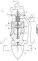
Fig. 1 illustrates an aircraft engine such as agas turbine engine 10 of a type preferably provided for use in subsonic flight, generally comprising in serial flow communication anengine inlet 12 through which ambient air is received, acompressor section 14 for pressurizing the air, acombustor 16 in which the compressed air is mixed with fuel and ignited for generating an annular stream of hot combustion gases, and aturbine section 18 for extracting energy from the combustion gases. - The
engine 10 includes at least one rotatable shaft defining acentral axis 20 of the engine. In the embodiment shown, two co-axial and independently rotatable shafts are provided: a low pressure orpower shaft 22, and ahigh pressure shaft 24. Thehigh pressure shaft 24 is driven by ahigh pressure portion 18H of theturbine section 18, and drives thecompressor section 14. Thelow pressure shaft 22 is driven by alow pressure portion 18L of theturbine section 18 which is located downstream of thehigh pressure portion 18H, and drives anoutput shaft 26 engaged to apropeller 28; theoutput shaft 26 is driven through areduction gearbox 30. - Although the
engine 10 is shown as a turboprop engine, it is understood that theengine 10 may have any suitable alternate configuration, including, but not limited to, a turboshaft configuration. Moreover, although theengine 10 is shown as a gas turbine engine, it is understood that the engine may have any other suitable configuration. - Aircraft intake is designed to deliver ambient air flow to engine. It is typically designed to supply air from an environment E outside the
engine 10 to the engine while minimizing pressure loss of the air circulating through the intake in different ambient weather conditions to minimize engine fuel consumption. In the meantime, the intake air flow should have less distortion and low swirl at entry of thecompressor 14, also referred to as compressor face or engine inlet, before entering the engine to have large surge margin. When theaircraft engine 10 is operating in wet weather, particularly in icing conditions, the intake is configured to bypass a large amount of icing particles directly back and out to the environment E to avoid engine flame out. - Referring to
Fig. 2 , an inertial particle separator (IPS) 40 in accordance with a particular embodiment is shown. The IPS 40 is configured for communicating with the engine inlet 12 (Fig. 1 ). Theparticle separator 40 generally includes an inlet duct, also referred to as an aircraft inlet, 42, an intermediate duct, also referred to as an engine entrance duct, 44, and abypass duct 46. - The
inlet duct 42 defines anintake 48 communicating with the environment E outside theengine 10. Theinlet duct 42 has a wall having anengine side 42a and anouter side 42b radially spaced from one another, with theouter side 42b being located radially outwardly of theengine side 42a with respect to thecentral axis 20 of theengine 10, i.e. theengine side 42a is located between thecentral axis 20 of theengine 10 and theouter side 42b. - In a particular embodiment, the
inlet duct 42 has an arcuate cross-section, and the engine andouter sides engine 10 andouter sides inlet duct 42 may have a circular, rectangular, kidney, or oval cross-section, in which case the engine andouter sides bypass ducts central axis 20 of theaircraft engine 10. A plenum or quasi-scroll may then be used to distribute the air exiting theintermediate duct 46 to thecompressor section 14. - The
intermediate duct 44 is in fluid communication with theinlet duct 42 adjacent its downstream end. Theintermediate duct 44 extends radially inwardly, generally transversally to theinlet duct 42, and is connected to theengine inlet 12. Theintermediate duct 44 has a wall with axially spaced apart upstream anddownstream wall portions - Still referring to
Fig. 2 , thebypass duct 46 is in fluid communication with theinlet duct 42 andintermediate duct 44, and extends downstream from theinlet duct 42. Thebypass duct 46 has a wall having anouter side 46b extending from a downstream end of theouter side 42b of the wall of theinlet duct 42. The wall of thebypass duct 46 also has anengine side 46a intersecting the wall of theintermediate duct 44, more particularly thedownstream wall portion 44d, at an intersection defining asplitter 50. Theinlet duct 42,intermediate duct 44 andbypass duct 46 thus communicate with each other at 54, and together generally define an "inverted T" shape. Thebypass duct 46 defines anoutlet 56 communicating with the environment E outside theengine 10. - It the present specification, including claims, the terms "intersection" and related terms (e.g. "intersects") are intended to encompass the point of attachment of walls manufactured separately and attached together through any suitable type of attachment, as well a point of transition (e.g., change of direction) between adjacent portions of a monolithic wall.
- In the embodiment shown, the
inlet duct 42 curves radially away from thecentral axis 20 of theaircraft engine 10 from theintake 48 to a mid-section 42c of theintermediate duct 44 and curves radially toward thecentral axis 20 from the mid-section 42c and toward theintermediate duct 44. In the depicted embodiment, thebypass duct 44 extends radially away from thecentral axis 20 downstream of thesplitter 50. - Typically, an ambient air flow F entering the
inlet duct 42 of the IPS 40 via theintake 48 splits into two streams F1, F2 one to engine and another to bypass. The location of thesplitter 50 influences separation efficiency and loss. When its position is more upstream relative to the flow F, the particles are less likely to go to theintermediate duct 44 because the engine entrance duct area is reduced. In such a case, the separation efficiency is better but the pressure loss becomes worse. A flat icing screen may be mounted at thesplitter 50. In the icing condition, the screen becomes iced up and clogged, resulting in higher separation efficiency. However, aerodynamic losses imparted on the flow F1 to theengine 10 when passing around the clogged screen are non-negligible. The pressure loss may surge due to the flow sudden contraction and expansion around the clogged sheet. This might induce high flow distortion and swirl, which are nondesirable. - Still referring to
Fig. 2 , asplitter vane 52 is located within theintermediate duct 44. Thesplitter vane 52 has a leadingedge 52a located upstream of thesplitter 50 relative to the flow F circulating in theinlet duct 42. Thesplitter vane 52 may have an aerodynamically-shaped profile. In the embodiment shown, thesplitter vane 52 has a symmetric airfoil, but any suitable airfoil may be used. Thesplitter vane 52 may be secured within theintermediate duct 44 via side wall portions of saidduct 44 connecting theupstream wall portion 44u to thedownstream wall portion 44d. Any suitable way of securing thesplitter vane 52 within theintermediate duct 44 is contemplated. - As shown in
Fig. 2 , thesplitter vane 52 is located between the upstream anddownstream wall portions intermediate duct 44. Theleading edge 52a of thesplitter vane 52 may be located radially outwardly of theintersection 50 between theintermediate duct 44 and the bypass duct. Alternatively, theleading edge 52a of thesplitter vane 52 may be located radially inwardly of theintersection 50. In other words, a radial distance between thecentral axis 20 and theleading edge 52a of thesplitter vane 52 is greater than that between thecentral axis 20 and thesplitter 50. In the embodiment shown, theleading edge 52a of thesplitter vane 52 is located upstream of theintersection 50 relative to the flow F. - The
splitter vane 52 has apressure side 52p and asuction side 52s opposed to thepressure side 52p. Both of the pressure andsuction sides leading edge 52a to a trailingedge 52b of thesplitter vane 52. As shown inFig. 3 , anextrapolation 52s' of thesuction side 52s (shown in dashed line inFig. 3 ) of thesplitter vane 52 merges with, or is aligned with, thedownstream wall portion 44d of theintermediate duct 44. In other words, the vanesuction side extrapolation 52s' is tangent with thedownstream wall portion 44d of theintermediate duct 44. In the embodiment shown, anextrapolation 46a' (shown in dashed line inFig. 3 ) of theengine side 46a of the wall of the bypass duct connects with theleading edge 52a of thesplitter vane 52. Such a configuration may allow to better guide particles into thebypass duct 46. An horizontal position of thesplitter vane 52 may be adjusted to achieve a balance between high separation efficiency and low pressure loss. - A
channel 60 is defined between thesplitter vane 52 and thedownstream wall portion 44d of theintermediate duct 44. - A cross-sectional area of the
channel 60 taken in a plane normal to a direction of an airflow circulating therethrough may be less than half of that of theintermediate duct 44. Stated differently, a distance from theupstream wall portion 44u of theintermediate duct 44 to thesplitter vane 52 may be greater than a distance from thesplitter vane 52 to thedownstream wall portion 44d of theintermediate duct 44. - Still referring to
Figs. 2-3 , aporous plate 62 is located across thechannel 60. The porous plate may be a perforated pate or a wire screen. Theplate 62 may define openings sized so as to aggregate icing droplets and be blocked by an ice coating under icing conditions. Theplate 62 may be secured to thedownstream wall portion 44d of theintermediate duct 44 and/or to thesplitter vane 52. In the present embodiment, theplate 62 is secured to both of thedownstream wall portion 44d of theintermediate duct 44 and to thesplitter vane 52. Theplate 62 may extend perpendicularly to thedownstream wall portion 44d of theintermediate duct 44 and/or perpendicularly to thesplitter vane 52. In other words, theplate 62 may be normal relative to a flow direction of an airflow circulating within thechannel 60. In a particular embodiment, to reduce pressure loss, the porous plate is inclined with respect to thedownstream wall portion 44d of theintermediate duct 44 to reduce the flow velocity across the plate. The angle may be adjusted depending of shape of the ducts. - The
plate 62 may be located halfway between the leading and trailingedges splitter vane 52. Stated differently, theplate 62 may be secured to thepressure side 52p of thesplitter vane 52 at a mid-chord location. Theplate 62 may be located at a mid-length of thechannel 60. Theplate 62 may be located anywhere within thechannel 60. - In a particular embodiment, the
plate 62 includes or is constituted by a screen (e.g. mesh material). A typical screen is made of wires having a diameter of 0.15 to 3.5 millimetres, preferably 0.6 mm and distanced from one another by a distance of 0.5 to 12 millimetres, preferably 6 mm. Other dimensions are also possible. Alternately, theplate 62 can be configured as a perforated plate, or be defined in part or in whole by open cell material such as honeycomb material. The openings may be circular, square, rectangular, elliptical and any other suitable shape. In a particular embodiment, a ratio of a total surface area of the openings over a surface area of theplate 62 ranges from about 50% to about 90%. Other configurations are also possible. - In icing conditions, the
channel 60 becomes ice-blocked or clogged by ice and all the air that reaches theengine inlet 12 circulates through theintermediate duct 44 between theupstream wall portion 44u and thesplitter vane 52. In such a case, a splitting location-that is a location where the flow circulating through theinlet duct 42 is split between theintermediate duct 44 and the bypass duct 46-corresponds to theleading edge 52a of thesplitter vane 52. In such a case, the cross-sectional area of the intermediate duct in which engine inlet flow can circulate is less, and the separation efficiency of theIPS 40 is greater, than what they would be if thechannel 60 were not clogged by ice. - In non-icing conditions, the
channel 60 is open and air can pass through theplate 62. In such a case, the splitting location moves downstream of theleading edge 52a of thesplitter vane 52 and corresponds to theintersection 50 between thedownstream wall portion 44d of theintermediate duct 44 and theengine side 46a of the wall of thebypass duct 46. Therefore, the cross-sectional area of the intermediate duct in which air can circulate is increased compared to that in the icing conditions and pressure loss is decreased compared to that in the icing conditions. In other words, the opening of thechannel 60 in non-icing conditions increases the flow area and therefore may decrease pressure loss. - The bypass splitting location of the
IPS 40 may be "smartly" movable from theleading edge 52a of thesplitter vane 52 to theintersection 50 between the intermediate andbypass ducts IPS 40 may therefore achieve high separation efficiency and low loss for different ambient weathers. TheIPS 40 may achieve high separation efficiency in icing conditions and low pressure loss in both icing and non-icing conditions. The pressure loss in non-icing conditions may be less than that in icing conditions. The airfoil shape of the splitting vane may allow the pressure loss to remain low in icing conditions. - Referring now to
Fig. 4 , an IPS in accordance with another embodiment is generally shown at 140. For the sake of conciseness, only elements that differ from theIPS 40 described above with reference toFigs. 2-3 are described herein below. - In this embodiment of the
IPS 140, thechannel 160 is defined by a duct connecting thebypass duct 46 to theintermediate duct 44. Thechannel 160 is located further downstream of theintersection 50 between the intermediate andbypass ducts channel 60 of theIPS 40 ofFigs. 2-3 . In the present embodiment, the splitter vane corresponds to asplitter body 152 having a substantially triangular shape. - The
splitter body 152 has opposedsides 152a each corresponding to a portion of a respective one of thedownstream wall portion 44d of theintermediate duct 44 and theengine side 46a of the wall of thebypass duct 46. TheIPS - Referring to
Figs. 2-4 , in a particular embodiment, theIPS 40 is initially designed to have a high particle separation efficiency and low pressure loss in icing operating conditions. That is, in the IPS designed for icing operating conditions, thesplitter vane 52 is absent and thesuction side 52s of what belongs to thesplitter vane 52 inFigs. 2-3 forms part of thedownstream wall portion 44d of theintermediate duct 44. Similarly, theengine side 46a of thebypass duct 46 extends such that the splitter, orintersection 50, is located at theleading edge 52a of thesplitter vane 52. Once the IPS is designed for high separation efficiency at icing operating conditions, thechannel 60 is generated thereby creating the splitter vane 52 (or thesplitter body 152 ofFig. 4 ). Thechannel 60 is in fluid communication with both of thebypass duct 46 and theintermediate duct 44. Thechannel 60 may allow to further reduce the pressure loss compared to the configuration before thechannel 60 is generated. - The
channel 60 may be generated by forming apertures through theengine side 46a of thebypass duct 46 and through thedownstream wall portion 44d of theintermediate duct 44.Side walls 60a may be added to complete thechannel 60. In the embodiment shown, theside walls 60a of thechannel 60 define thepressure side 52p of thesplitter vane 52 and a portion of thedownstream wall portion 44d of theintermediate duct 44. In other words, thesplitter vane 52 may be defined by one of theopposed side walls 60a of thechannel 60 and by a portion of thedownstream wall portion 44d of theintermediate duct 44 that extends from theleading edge 52a to thechannel 60. For theIPS 140 ofFig. 4 , thesplitter body 152 may be defined by one of opposed side walls ofchannel 160, by a portion (denoted by 152a onFig. 4 ) of theengine side 46a of the wall of thebypass duct 46, and by a portion (denoted by 152a onFig. 4 ) of thedownstream wall portion 44d of theintermediate duct 44. Thechannel 60 may be defined through a portion of theengine side 46a of the wall of thebypass duct 46; the portion extending radially toward thecentral axis 20 of theaircraft engine 10 in a downstream direction relative to the flow F. - For separating particles of ice from a flow of ambient air in an aircraft engine, the flow of ambient air is received from the environment E outside the
aircraft engine 10 within theinlet duct 42. In non-icing conditions, the flow of ambient air is split at theintersection 50 between theintermediate duct 44 stemming from theinlet duct 42 and thebypass duct 46 extending downstream of theinlet duct 42. In icing conditions, the icing particles are circulated through theporous plate 62 extending across thechannel 60 defined between thesplitter vane 52 within theintermediate duct 44 and thedownstream wall portion 44d of theintermediate duct 44. The flow of ambient air is split at theleading edge 52a of thesplitter vane 52 being located upstream of theintersection 50 upon thechannel 60 being clogged by ice. - In the embodiment shown, circulating the icing particles through the
porous plate 62 includes circulating the icing particles through a screen made with wires having a diameter ranging from 0.15 to 3.5 millimeters and spaced apart from one another by a distance ranging from 0.5 to 12 millimeters. - The above description is meant to be exemplary only, and one skilled in the art will recognize that changes may be made to the embodiments described without departing from the scope of the invention disclosed. Still other modifications which fall within the scope of the appended claims will be apparent to those skilled in the art, in light of a review of this disclosure, and such modifications are intended to fall within the scope of the present invention.
Claims (15)
- An aircraft engine (10) comprising an inertial particle separator (IPS) (40) communicating with an engine inlet (12) of the aircraft engine (10), the IPS comprising:an inlet duct (42) defining an intake (48) communicating with an environment (E) of the aircraft engine(10);an intermediate duct (44) extending from the inlet duct (42) to the engine inlet (12);a bypass duct (46) in fluid communication with and extending downstream from the inlet duct (42), the bypass duct (46) defining an outlet (56) communicating with the environment (E) of the aircraft engine (10), a splitter (50) defined at an intersection of a wall (46a) of the bypass duct (46) and a wall (44d) of the intermediate duct (44);a splitter vane (52) within the intermediate duct (44) and having a leading edge (52a) located upstream of the splitter (50) relative to a flow (F) circulating through the IPS (40), the splitter vane (52) and the wall (44d) of the intermediate duct (44) defining a channel (60) therebetween; and characterised bya porous plate (62) extending across the channel (60) and defining openings sized so as to aggregate ice and be blocked by ice under icing conditions, such that in icing conditions the channel (60) becomes ice-blocked, and in non-icing conditions, the channel (60) is open.
- The aircraft engine (10) of claim 1, wherein the splitter vane (52) has an airfoil-shaped cross-section.
- The aircraft engine (10) of claim 1 or 2, wherein an extrapolation (46a') of the wall (46a) of the bypass duct (46) connects the leading edge (52a) of the splitter vane (52) and wherein an extrapolation (52s') of a suction side (52s) of the splitter vane (52) tangentially merges with the wall (44d) of the intermediate duct (44).
- The aircraft engine (10) of claim 1, 2 or 3, wherein the leading edge (52a) of the splitter vane (52) is located radially outwardly of the splitter (50) relative to a central axis (20) of the aircraft engine (10).
- The aircraft engine (10) of any preceding claim, wherein the splitter vane (52) has a chord length extending from the leading edge (52a) to a trailing edge (52b) thereof, the plate (62) located at mid-chord between the leading edge (52a) and the trailing edge (52b).
- The aircraft engine (10) of any preceding claim, wherein the plate (62) perpendicularly intersects the splitter vane (52) and/or the wall (44d) of the intermediate duct (44).
- An aircraft engine (10) comprising an inertial particle separator (IPS) (140) communicating with an engine inlet (12) of the aircraft engine (10), the IPS comprising:an inlet duct (42) defining an intake (48) communicating with an environment (E) outside the aircraft engine (10);an intermediate duct (44) extending from the inlet duct (42) to the engine inlet (12);a bypass duct (46) in fluid communication with and extending downstream from the inlet duct (42), the bypass duct (46) defining an outlet (56) communicating with the environment (E) of the aircraft engine (10), a splitter (50) provided at an intersection of a wall (46a) of the bypass duct (46) and a wall (44d) of the intermediate duct (44);a channel (160) extending through both of the wall (46a) of the bypass duct (46) and the wall (44d) of the intermediate duct (44); and characterised bya porous plate (62) located across the channel (160) and defining openings sized so as to aggregate icing droplets and be blocked by an ice coating under icing conditions, such that in icing conditions the channel (160) becomes ice-blocked, and in non-icing conditions, the channel (160) is open.
- The aircraft engine (10) of claim 7, wherein the channel (160) has opposed side walls, and a splitter vane (152) is defined by one of the opposed side walls of the channel (160) and by a portion of the wall (152a) of the intermediate duct (44) extending from the intersection to the channel (160), wherein, optionally, the intersection is defined by a leading edge of the splitter vane (152).
- The aircraft engine (10) of claim 7 or 8, wherein the channel (160) is defined through a portion of the wall (46a) of the bypass duct (46) that extends radially toward a central axis (20) of the aircraft engine (10) in a downstream direction relative to a flow (F) circulating through the bypass duct (46).
- The aircraft engine (10) of claim 7, 8 or 9, wherein the porous plate (62) is located at mid-length of the channel (160), and/or is normal relative to a flow direction (F) of an airflow circulating therethrough.
- The aircraft engine (10) of any of claims 7 to 10, wherein a cross-sectional area of the channel (160) is less than that of the intermediate duct (44).
- The aircraft engine (10) of any preceding claim, wherein the inlet duct (42) curves radially away from a/the central axis (20) of the aircraft engine (10) from the intake (12) to a mid-section (42c) of the inlet duct (42) and curves radially toward the central axis (20) from the mid-section (42c) to the splitter (50).
- The aircraft engine (10) of any preceding claim, wherein the bypass duct (46) extends radially away from a/the central axis (20) of the aircraft engine (10) downstream of the splitter (50).
- A method of separating particles from a flow of ambient air in an aircraft engine (10), comprising:receiving the flow of ambient air from an environment (E) outside the aircraft engine (10) within an inlet duct (42);in non-icing conditions, splitting the flow of ambient air at an intersection between an intermediate duct (44) stemming from the inlet duct (42) and a bypass duct (46) extending downstream of the inlet duct (42); and characterised byin icing conditions, circulating icing particles through a porous plate (62) extending across a channel (60) defined between a splitter vane (52) within the intermediate duct (44) and a wall (44d) of the intermediate duct (44), and splitting the flow of ambient air at a leading edge (52a) of the splitter vane upstream of the intersection upon the channel (60) being clogged by ice.
- The aircraft engine (10) of any of claims 1 to 13 or the method of claim 14, wherein the porous plate (62) is a screen made with wires having a diameter ranging from 0.15 to 3.5 millimeters and spaced apart from one another by a distance ranging from 0.5 to 12 millimeters.
Applications Claiming Priority (1)
| Application Number | Priority Date | Filing Date | Title |
|---|---|---|---|
| US16/573,013 US11339716B2 (en) | 2019-09-17 | 2019-09-17 | Inertial particle separator for aircraft engine |
Publications (2)
| Publication Number | Publication Date |
|---|---|
| EP3795475A1 EP3795475A1 (en) | 2021-03-24 |
| EP3795475B1 true EP3795475B1 (en) | 2023-02-22 |
Family
ID=72560467
Family Applications (1)
| Application Number | Title | Priority Date | Filing Date |
|---|---|---|---|
| EP20196673.6A Active EP3795475B1 (en) | 2019-09-17 | 2020-09-17 | Inertial particle separator for aircraft engine |
Country Status (2)
| Country | Link |
|---|---|
| US (1) | US11339716B2 (en) |
| EP (1) | EP3795475B1 (en) |
Families Citing this family (4)
| Publication number | Priority date | Publication date | Assignee | Title |
|---|---|---|---|---|
| US11066996B2 (en) * | 2018-04-27 | 2021-07-20 | Pratt & Whitney Canada Corp. | Gas turbine engine with inertial particle separator |
| US11560844B2 (en) * | 2021-02-18 | 2023-01-24 | Pratt & Whitney Canada Corp. | Inertial particle separator for a turbine section of a gas turbine engine |
| CN113510130B (en) * | 2021-06-08 | 2024-06-21 | 天津中鑫轨道交通设备有限公司 | Flow equalizer |
| CN113895636B (en) * | 2021-11-18 | 2024-01-05 | 北京机电工程研究所 | Buried type stealth air inlet channel |
Family Cites Families (11)
| Publication number | Priority date | Publication date | Assignee | Title |
|---|---|---|---|---|
| US3329377A (en) * | 1965-10-11 | 1967-07-04 | United Aircraft Canada | Protection for aircraft engines against snow, ice and airborne particles |
| US4844382A (en) * | 1983-10-19 | 1989-07-04 | Raisbeck Engineering, Inc. | Dual turning vane air inlet assembly |
| US4702071A (en) | 1985-06-28 | 1987-10-27 | Rolls-Royce Plc | Inlet particle separator |
| GB2250693B (en) * | 1990-09-25 | 1994-01-26 | Rolls Royce Plc | Improvements in or relating to air intakes for gas turbine engines |
| CA2859441C (en) | 2013-08-16 | 2021-10-12 | Eric Loth | Particle separator |
| US10167725B2 (en) | 2014-10-31 | 2019-01-01 | General Electric Company | Engine component for a turbine engine |
| GB201503123D0 (en) | 2015-02-25 | 2015-04-08 | Rolls Royce Plc | Fluid intake |
| US10508626B2 (en) * | 2016-10-14 | 2019-12-17 | Pratt & Whitney Canada Corp. | Auxiliary power unit inlet assembly with filter |
| US10245540B2 (en) * | 2017-01-09 | 2019-04-02 | Pratt & Whitney Canada Corp. | Inertial particle separator for engine inlet |
| US10513979B2 (en) | 2017-01-24 | 2019-12-24 | General Electric Company | Asymmetric inlet particle separator system |
| RU2671256C1 (en) | 2017-09-28 | 2018-10-30 | Юрий Яковлевич Ситницкий | Air-intake device for a helicopter gas turbine engine removing air sand particles, dust and other imparents from air |
-
2019
- 2019-09-17 US US16/573,013 patent/US11339716B2/en active Active
-
2020
- 2020-09-17 EP EP20196673.6A patent/EP3795475B1/en active Active
Also Published As
| Publication number | Publication date |
|---|---|
| US20210079840A1 (en) | 2021-03-18 |
| EP3795475A1 (en) | 2021-03-24 |
| US11339716B2 (en) | 2022-05-24 |
Similar Documents
| Publication | Publication Date | Title |
|---|---|---|
| EP3795475B1 (en) | Inertial particle separator for aircraft engine | |
| US10765980B2 (en) | Inertial particle separator for engine inlet | |
| US12565842B2 (en) | Airfoil having a film hole | |
| US8484982B2 (en) | Bleed structure for a bleed passage in a gas turbine engine | |
| CA2725801C (en) | Rotor assembly with cooling air deflectors and method | |
| EP2903894B1 (en) | Bifurcated inlet scoop for gas turbine engine | |
| EP3260687A1 (en) | Inlet particle separator system with pre-cleaner flow passage | |
| EP3561265B1 (en) | Gas turbine engine with inertial particle separator | |
| US10598191B2 (en) | Vane for turbomachinery, such as an aircraft turbojet or turbofan engine or an aircraft turboprop engine | |
| US10400670B2 (en) | Inlet particle separator for a turbine engine | |
| US20180066604A1 (en) | Integrated turbine exhaust struts and mixer of turbofan engine | |
| US20170234141A1 (en) | Airfoil having crossover holes | |
| EP2905227A1 (en) | Bifurcated ducts including plenums for stabilizing flow therethrough and exhaust systems including the same | |
| US11608782B2 (en) | Axial inertial particle separator for turbine engine | |
| US11261789B2 (en) | Inertial particle separator for turbine engine | |
| CA2909564C (en) | Turbine exhaust case with mixer including alternating deswirling and secondary struts | |
| CA2598983A1 (en) | A bleed structure for a bleed passage in a gas turbine engine | |
| EP4343115B1 (en) | Airfoil for an aircraft engine comprising a slot |
Legal Events
| Date | Code | Title | Description |
|---|---|---|---|
| PUAI | Public reference made under article 153(3) epc to a published international application that has entered the european phase |
Free format text: ORIGINAL CODE: 0009012 |
|
| STAA | Information on the status of an ep patent application or granted ep patent |
Free format text: STATUS: THE APPLICATION HAS BEEN PUBLISHED |
|
| AK | Designated contracting states |
Kind code of ref document: A1 Designated state(s): AL AT BE BG CH CY CZ DE DK EE ES FI FR GB GR HR HU IE IS IT LI LT LU LV MC MK MT NL NO PL PT RO RS SE SI SK SM TR |
|
| AX | Request for extension of the european patent |
Extension state: BA ME |
|
| STAA | Information on the status of an ep patent application or granted ep patent |
Free format text: STATUS: REQUEST FOR EXAMINATION WAS MADE |
|
| 17P | Request for examination filed |
Effective date: 20210917 |
|
| RBV | Designated contracting states (corrected) |
Designated state(s): AL AT BE BG CH CY CZ DE DK EE ES FI FR GB GR HR HU IE IS IT LI LT LU LV MC MK MT NL NO PL PT RO RS SE SI SK SM TR |
|
| GRAP | Despatch of communication of intention to grant a patent |
Free format text: ORIGINAL CODE: EPIDOSNIGR1 |
|
| STAA | Information on the status of an ep patent application or granted ep patent |
Free format text: STATUS: GRANT OF PATENT IS INTENDED |
|
| INTG | Intention to grant announced |
Effective date: 20220829 |
|
| GRAS | Grant fee paid |
Free format text: ORIGINAL CODE: EPIDOSNIGR3 |
|
| GRAA | (expected) grant |
Free format text: ORIGINAL CODE: 0009210 |
|
| STAA | Information on the status of an ep patent application or granted ep patent |
Free format text: STATUS: THE PATENT HAS BEEN GRANTED |
|
| AK | Designated contracting states |
Kind code of ref document: B1 Designated state(s): AL AT BE BG CH CY CZ DE DK EE ES FI FR GB GR HR HU IE IS IT LI LT LU LV MC MK MT NL NO PL PT RO RS SE SI SK SM TR |
|
| REG | Reference to a national code |
Ref country code: GB Ref legal event code: FG4D |
|
| REG | Reference to a national code |
Ref country code: CH Ref legal event code: EP |
|
| REG | Reference to a national code |
Ref country code: DE Ref legal event code: R096 Ref document number: 602020008244 Country of ref document: DE |
|
| REG | Reference to a national code |
Ref country code: AT Ref legal event code: REF Ref document number: 1549351 Country of ref document: AT Kind code of ref document: T Effective date: 20230315 Ref country code: IE Ref legal event code: FG4D |
|
| REG | Reference to a national code |
Ref country code: LT Ref legal event code: MG9D |
|
| REG | Reference to a national code |
Ref country code: NL Ref legal event code: MP Effective date: 20230222 |
|
| P01 | Opt-out of the competence of the unified patent court (upc) registered |
Effective date: 20230530 |
|
| REG | Reference to a national code |
Ref country code: AT Ref legal event code: MK05 Ref document number: 1549351 Country of ref document: AT Kind code of ref document: T Effective date: 20230222 |
|
| PG25 | Lapsed in a contracting state [announced via postgrant information from national office to epo] |
Ref country code: RS Free format text: LAPSE BECAUSE OF FAILURE TO SUBMIT A TRANSLATION OF THE DESCRIPTION OR TO PAY THE FEE WITHIN THE PRESCRIBED TIME-LIMIT Effective date: 20230222 Ref country code: PT Free format text: LAPSE BECAUSE OF FAILURE TO SUBMIT A TRANSLATION OF THE DESCRIPTION OR TO PAY THE FEE WITHIN THE PRESCRIBED TIME-LIMIT Effective date: 20230622 Ref country code: NO Free format text: LAPSE BECAUSE OF FAILURE TO SUBMIT A TRANSLATION OF THE DESCRIPTION OR TO PAY THE FEE WITHIN THE PRESCRIBED TIME-LIMIT Effective date: 20230522 Ref country code: NL Free format text: LAPSE BECAUSE OF FAILURE TO SUBMIT A TRANSLATION OF THE DESCRIPTION OR TO PAY THE FEE WITHIN THE PRESCRIBED TIME-LIMIT Effective date: 20230222 Ref country code: LV Free format text: LAPSE BECAUSE OF FAILURE TO SUBMIT A TRANSLATION OF THE DESCRIPTION OR TO PAY THE FEE WITHIN THE PRESCRIBED TIME-LIMIT Effective date: 20230222 Ref country code: LT Free format text: LAPSE BECAUSE OF FAILURE TO SUBMIT A TRANSLATION OF THE DESCRIPTION OR TO PAY THE FEE WITHIN THE PRESCRIBED TIME-LIMIT Effective date: 20230222 Ref country code: HR Free format text: LAPSE BECAUSE OF FAILURE TO SUBMIT A TRANSLATION OF THE DESCRIPTION OR TO PAY THE FEE WITHIN THE PRESCRIBED TIME-LIMIT Effective date: 20230222 Ref country code: ES Free format text: LAPSE BECAUSE OF FAILURE TO SUBMIT A TRANSLATION OF THE DESCRIPTION OR TO PAY THE FEE WITHIN THE PRESCRIBED TIME-LIMIT Effective date: 20230222 Ref country code: AT Free format text: LAPSE BECAUSE OF FAILURE TO SUBMIT A TRANSLATION OF THE DESCRIPTION OR TO PAY THE FEE WITHIN THE PRESCRIBED TIME-LIMIT Effective date: 20230222 |
|
| PG25 | Lapsed in a contracting state [announced via postgrant information from national office to epo] |
Ref country code: SE Free format text: LAPSE BECAUSE OF FAILURE TO SUBMIT A TRANSLATION OF THE DESCRIPTION OR TO PAY THE FEE WITHIN THE PRESCRIBED TIME-LIMIT Effective date: 20230222 Ref country code: PL Free format text: LAPSE BECAUSE OF FAILURE TO SUBMIT A TRANSLATION OF THE DESCRIPTION OR TO PAY THE FEE WITHIN THE PRESCRIBED TIME-LIMIT Effective date: 20230222 Ref country code: IS Free format text: LAPSE BECAUSE OF FAILURE TO SUBMIT A TRANSLATION OF THE DESCRIPTION OR TO PAY THE FEE WITHIN THE PRESCRIBED TIME-LIMIT Effective date: 20230622 Ref country code: GR Free format text: LAPSE BECAUSE OF FAILURE TO SUBMIT A TRANSLATION OF THE DESCRIPTION OR TO PAY THE FEE WITHIN THE PRESCRIBED TIME-LIMIT Effective date: 20230523 Ref country code: FI Free format text: LAPSE BECAUSE OF FAILURE TO SUBMIT A TRANSLATION OF THE DESCRIPTION OR TO PAY THE FEE WITHIN THE PRESCRIBED TIME-LIMIT Effective date: 20230222 |
|
| PG25 | Lapsed in a contracting state [announced via postgrant information from national office to epo] |
Ref country code: SM Free format text: LAPSE BECAUSE OF FAILURE TO SUBMIT A TRANSLATION OF THE DESCRIPTION OR TO PAY THE FEE WITHIN THE PRESCRIBED TIME-LIMIT Effective date: 20230222 Ref country code: RO Free format text: LAPSE BECAUSE OF FAILURE TO SUBMIT A TRANSLATION OF THE DESCRIPTION OR TO PAY THE FEE WITHIN THE PRESCRIBED TIME-LIMIT Effective date: 20230222 Ref country code: EE Free format text: LAPSE BECAUSE OF FAILURE TO SUBMIT A TRANSLATION OF THE DESCRIPTION OR TO PAY THE FEE WITHIN THE PRESCRIBED TIME-LIMIT Effective date: 20230222 Ref country code: DK Free format text: LAPSE BECAUSE OF FAILURE TO SUBMIT A TRANSLATION OF THE DESCRIPTION OR TO PAY THE FEE WITHIN THE PRESCRIBED TIME-LIMIT Effective date: 20230222 Ref country code: CZ Free format text: LAPSE BECAUSE OF FAILURE TO SUBMIT A TRANSLATION OF THE DESCRIPTION OR TO PAY THE FEE WITHIN THE PRESCRIBED TIME-LIMIT Effective date: 20230222 |
|
| REG | Reference to a national code |
Ref country code: DE Ref legal event code: R097 Ref document number: 602020008244 Country of ref document: DE |
|
| PG25 | Lapsed in a contracting state [announced via postgrant information from national office to epo] |
Ref country code: SK Free format text: LAPSE BECAUSE OF FAILURE TO SUBMIT A TRANSLATION OF THE DESCRIPTION OR TO PAY THE FEE WITHIN THE PRESCRIBED TIME-LIMIT Effective date: 20230222 |
|
| PLBE | No opposition filed within time limit |
Free format text: ORIGINAL CODE: 0009261 |
|
| STAA | Information on the status of an ep patent application or granted ep patent |
Free format text: STATUS: NO OPPOSITION FILED WITHIN TIME LIMIT |
|
| 26N | No opposition filed |
Effective date: 20231123 |
|
| PG25 | Lapsed in a contracting state [announced via postgrant information from national office to epo] |
Ref country code: SI Free format text: LAPSE BECAUSE OF FAILURE TO SUBMIT A TRANSLATION OF THE DESCRIPTION OR TO PAY THE FEE WITHIN THE PRESCRIBED TIME-LIMIT Effective date: 20230222 |
|
| REG | Reference to a national code |
Ref country code: CH Ref legal event code: PL |
|
| PG25 | Lapsed in a contracting state [announced via postgrant information from national office to epo] |
Ref country code: LU Free format text: LAPSE BECAUSE OF NON-PAYMENT OF DUE FEES Effective date: 20230917 |
|
| REG | Reference to a national code |
Ref country code: BE Ref legal event code: MM Effective date: 20230930 |
|
| PG25 | Lapsed in a contracting state [announced via postgrant information from national office to epo] |
Ref country code: LU Free format text: LAPSE BECAUSE OF NON-PAYMENT OF DUE FEES Effective date: 20230917 Ref country code: IT Free format text: LAPSE BECAUSE OF FAILURE TO SUBMIT A TRANSLATION OF THE DESCRIPTION OR TO PAY THE FEE WITHIN THE PRESCRIBED TIME-LIMIT Effective date: 20230222 Ref country code: MC Free format text: LAPSE BECAUSE OF FAILURE TO SUBMIT A TRANSLATION OF THE DESCRIPTION OR TO PAY THE FEE WITHIN THE PRESCRIBED TIME-LIMIT Effective date: 20230222 |
|
| REG | Reference to a national code |
Ref country code: IE Ref legal event code: MM4A |
|
| PG25 | Lapsed in a contracting state [announced via postgrant information from national office to epo] |
Ref country code: IE Free format text: LAPSE BECAUSE OF NON-PAYMENT OF DUE FEES Effective date: 20230917 |
|
| PG25 | Lapsed in a contracting state [announced via postgrant information from national office to epo] |
Ref country code: CH Free format text: LAPSE BECAUSE OF NON-PAYMENT OF DUE FEES Effective date: 20230930 |
|
| PG25 | Lapsed in a contracting state [announced via postgrant information from national office to epo] |
Ref country code: IE Free format text: LAPSE BECAUSE OF NON-PAYMENT OF DUE FEES Effective date: 20230917 Ref country code: CH Free format text: LAPSE BECAUSE OF NON-PAYMENT OF DUE FEES Effective date: 20230930 |
|
| PG25 | Lapsed in a contracting state [announced via postgrant information from national office to epo] |
Ref country code: BE Free format text: LAPSE BECAUSE OF NON-PAYMENT OF DUE FEES Effective date: 20230930 |
|
| PG25 | Lapsed in a contracting state [announced via postgrant information from national office to epo] |
Ref country code: BG Free format text: LAPSE BECAUSE OF FAILURE TO SUBMIT A TRANSLATION OF THE DESCRIPTION OR TO PAY THE FEE WITHIN THE PRESCRIBED TIME-LIMIT Effective date: 20230222 |
|
| PG25 | Lapsed in a contracting state [announced via postgrant information from national office to epo] |
Ref country code: BG Free format text: LAPSE BECAUSE OF FAILURE TO SUBMIT A TRANSLATION OF THE DESCRIPTION OR TO PAY THE FEE WITHIN THE PRESCRIBED TIME-LIMIT Effective date: 20230222 |
|
| PG25 | Lapsed in a contracting state [announced via postgrant information from national office to epo] |
Ref country code: CY Free format text: LAPSE BECAUSE OF FAILURE TO SUBMIT A TRANSLATION OF THE DESCRIPTION OR TO PAY THE FEE WITHIN THE PRESCRIBED TIME-LIMIT; INVALID AB INITIO Effective date: 20200917 |
|
| PG25 | Lapsed in a contracting state [announced via postgrant information from national office to epo] |
Ref country code: HU Free format text: LAPSE BECAUSE OF FAILURE TO SUBMIT A TRANSLATION OF THE DESCRIPTION OR TO PAY THE FEE WITHIN THE PRESCRIBED TIME-LIMIT; INVALID AB INITIO Effective date: 20200917 |
|
| PGFP | Annual fee paid to national office [announced via postgrant information from national office to epo] |
Ref country code: DE Payment date: 20250820 Year of fee payment: 6 |
|
| PGFP | Annual fee paid to national office [announced via postgrant information from national office to epo] |
Ref country code: GB Payment date: 20250820 Year of fee payment: 6 |
|
| PGFP | Annual fee paid to national office [announced via postgrant information from national office to epo] |
Ref country code: FR Payment date: 20250820 Year of fee payment: 6 |
|
| PG25 | Lapsed in a contracting state [announced via postgrant information from national office to epo] |
Ref country code: TR Free format text: LAPSE BECAUSE OF FAILURE TO SUBMIT A TRANSLATION OF THE DESCRIPTION OR TO PAY THE FEE WITHIN THE PRESCRIBED TIME-LIMIT Effective date: 20230222 |