EP2905227A1 - Bifurcated ducts including plenums for stabilizing flow therethrough and exhaust systems including the same - Google Patents
Bifurcated ducts including plenums for stabilizing flow therethrough and exhaust systems including the same Download PDFInfo
- Publication number
- EP2905227A1 EP2905227A1 EP15152396.6A EP15152396A EP2905227A1 EP 2905227 A1 EP2905227 A1 EP 2905227A1 EP 15152396 A EP15152396 A EP 15152396A EP 2905227 A1 EP2905227 A1 EP 2905227A1
- Authority
- EP
- European Patent Office
- Prior art keywords
- exhaust
- exhaust duct
- plenum
- duct
- bifurcated
- Prior art date
- Legal status (The legal status is an assumption and is not a legal conclusion. Google has not performed a legal analysis and makes no representation as to the accuracy of the status listed.)
- Granted
Links
Images

Classifications
-
- B—PERFORMING OPERATIONS; TRANSPORTING
- B64—AIRCRAFT; AVIATION; COSMONAUTICS
- B64D—EQUIPMENT FOR FITTING IN OR TO AIRCRAFT; FLIGHT SUITS; PARACHUTES; ARRANGEMENTS OR MOUNTING OF POWER PLANTS OR PROPULSION TRANSMISSIONS IN AIRCRAFT
- B64D33/00—Arrangements in aircraft of power plant parts or auxiliaries not otherwise provided for
- B64D33/04—Arrangements in aircraft of power plant parts or auxiliaries not otherwise provided for of exhaust outlets or jet pipes
-
- F—MECHANICAL ENGINEERING; LIGHTING; HEATING; WEAPONS; BLASTING
- F01—MACHINES OR ENGINES IN GENERAL; ENGINE PLANTS IN GENERAL; STEAM ENGINES
- F01D—NON-POSITIVE DISPLACEMENT MACHINES OR ENGINES, e.g. STEAM TURBINES
- F01D25/00—Component parts, details, or accessories, not provided for in, or of interest apart from, other groups
- F01D25/30—Exhaust heads, chambers, or the like
-
- F—MECHANICAL ENGINEERING; LIGHTING; HEATING; WEAPONS; BLASTING
- F05—INDEXING SCHEMES RELATING TO ENGINES OR PUMPS IN VARIOUS SUBCLASSES OF CLASSES F01-F04
- F05D—INDEXING SCHEME FOR ASPECTS RELATING TO NON-POSITIVE-DISPLACEMENT MACHINES OR ENGINES, GAS-TURBINES OR JET-PROPULSION PLANTS
- F05D2220/00—Application
- F05D2220/30—Application in turbines
- F05D2220/32—Application in turbines in gas turbines
- F05D2220/324—Application in turbines in gas turbines to drive unshrouded, low solidity propeller
-
- F—MECHANICAL ENGINEERING; LIGHTING; HEATING; WEAPONS; BLASTING
- F05—INDEXING SCHEMES RELATING TO ENGINES OR PUMPS IN VARIOUS SUBCLASSES OF CLASSES F01-F04
- F05D—INDEXING SCHEME FOR ASPECTS RELATING TO NON-POSITIVE-DISPLACEMENT MACHINES OR ENGINES, GAS-TURBINES OR JET-PROPULSION PLANTS
- F05D2250/00—Geometry
- F05D2250/20—Three-dimensional
- F05D2250/23—Three-dimensional prismatic
- F05D2250/232—Three-dimensional prismatic conical
Definitions
- the present invention generally relates to gas turbine engines, and more particularly relates to bifurcated ducts including plenums for stabilizing flow therethrough and to exhaust systems including the same.
- a gas turbine engine combusts a mixture of compressed air and fuel to produce hot combustion gases.
- the combustion gases flow through one or more stages of turbine blades to generate power.
- the power output of the gas turbine engine may be utilized in a variety of different manners, depending upon whether the gas turbine engine assumes the form of a turbofan, turboprop, turboshaft, turbojet engine, or an auxiliary power unit, to list but a few examples.
- the gas turbine engine conveys the combustion gases into a diffuser in an exhaust section that reduces energy of the combustion gases prior to discharge into the atmosphere.
- the reduced-energy combustion gases are referred to herein as "exhaust gas”.
- the exhaust gas may enter a bifurcated duct (more particularly, a plenum of a bifurcated duct).
- a bifurcated duct may be used in a single engine airplane where the engine is in the front of the aircraft and a firewall prevents passage of the exhaust gas through the aft portion of the engine compartment. Therefore, the bifurcated duct splits the flow of exhaust gas, directing a portion of the exhaust gas in one direction through a first exhaust duct and directing another portion of the exhaust gas in another direction through a second exhaust duct for discharge into the atmosphere on both sides of the airplane, thereby bypassing the firewall.
- the exhaust gas enters a high-volume plenum that causes a sudden expansion and turning of the flow, increasing turbulence and unsteady flow behavior inside the plenum and producing nonuniform flow to downstream components.
- the high-volume plenum abruptly guides the exhaust gas at an angle away from the first longitudinal axis of the gas turbine engine (e.g., approximately 90 degrees) into the first and second exhaust ducts. This abrupt change in the direction of flow (e.g., axial to radial) increases the turbulence (e.g. swirling motion of the gas) and flow separation, thereby significantly increasing backpressure.
- bifurcated ducts (inclusive of bifurcated exhaust ducts) including plenums for stabilizing flow therethrough and for exhaust systems including the same.
- plenums for stabilizing flow therethrough and for exhaust systems including the same.
- backpressure, flow separation, unsteady flow, and turbulence within the bifurcated ducts, thereby reducing noise and damage to surrounding structures.
- a plenum for a bifurcated duct comprises an outer cylindrical body intersected by a pair of exhaust duct stubs that are configured to be coupled to a corresponding pair of exhaust ducts and an inner body.
- the outer cylindrical body includes an axial rear end portion.
- the inner body is disposed in the axial rear end portion and increases in diameter in the aft direction.
- the inner body comprises one of a generally axi-symmetrical body or a non-axi-symmetrical body.
- a bifurcated duct comprises a plenum and a pair of exhaust ducts.
- the plenum comprises an outer cylindrical body intersected by a pair of exhaust duct stubs and an inner body.
- the outer cylindrical body includes an axial rear end portion.
- the inner body is disposed in the axial rear end portion and increases in diameter in the aft direction.
- the inner body comprises one of a generally axi-symmetrical inner body or a non-axi-symmetrical inner body.
- the pair of exhaust ducts is coupled to the pair of exhaust duct stubs.
- the exhaust system comprises a gas turbine engine comprising an exhaust section including a diffuser and a bifurcated exhaust duct in communication with the diffuser.
- the bifurcated exhaust duct comprises a plenum and a pair of exhaust ducts.
- the plenum comprises an outer cylindrical body intersected by a pair of exhaust duct stubs and an inner body.
- the outer cylindrical body includes an axial rear end portion.
- the inner body is disposed in the axial rear end portion and increases in diameter in the aft direction.
- the inner body comprises one of a generally axi-symmetrical inner body or a non-axi-symmetrical inner body
- the pair of exhaust ducts is coupled to the pair of exhaust duct stubs.
- Various embodiments are directed to bifurcated ducts including plenums for stabilizing flow therethrough and exhaust systems including the same.
- the various embodiments provide reduced turbulence, flow separation, and backpressure in the bifurcated ducts, reducing noise and damage to surrounding structures that are normally created by unsteady fluid flow through conventional bifurcated ducts.
- the terms "unitary”, “integrally-formed, and “integral” mean a one-piece seamless structure and excludes means for maintaining parts in a fixed relationship as a single unit.
- the term "bifurcated duct” includes a bifurcated exhaust duct that is used in an exhaust system for a gas turbine engine.
- bifurcated exhaust ducts in exhaust systems for aircraft gas turbine engines, the teachings of the present invention are generally applicable to any bifurcated duct for stabilizing flow therethrough to reduce turbulence, unsteady flow, flow separation, and backpressure therein.
- Exemplary bifurcated ducts include, but are not limited to, bifurcated water ducts, bifurcated air conditioning ducts, bifurcated automobile ducts, etc.
- the gas turbine engine may be incorporated into an aircraft, a watercraft, a locomotive, a power generation system, or combinations thereof.
- the gas turbine engine may assume the form of a turbofan, turboprop, turboshaft, turbojet engine, or an auxiliary power unit, to list but a few examples.
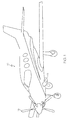
- FIG. 1 depicts an exemplary airplane 10 having a forward portion ( FIG. 2 ) that includes an exemplary turboprop gas turbine engine 14 attached to a propeller 16 in a known configuration.
- the illustrated gas turbine engine 14 of FIG. 2 includes a gearbox 12, an intake section 28, a compressor 18, a combustor section 20, a turbine 22, and an exhaust section 24.
- the turbine 22 is drivingly coupled to the compressor 18 via a shaft 26 oriented along a first longitudinal axis of the gas turbine engine.
- air may enter the gas turbine engine through an intake section 28 and flow into the compressor 18, which compresses the air prior to entry into the combustor section 20.
- the illustrated combustor section includes a combustor housing 30 disposed concentrically or annularly about the shaft 26 axially between the compressor and the turbine.
- the compressed air from the compressor 18 enters combustors where the compressed air may mix and combust with fuel within the combustors to drive the turbine.
- the hot combustion gases 32 flow through the turbine 22, driving the compressor via the shaft.
- the combustion gases may apply motive forces to turbine rotor blades within the turbine 22 to rotate the shaft 26 that drives the propeller 16.
- the hot combustion gases may exit the gas turbine engine 14 through the exhaust section 24.
- the exhaust section 24 is located behind the turbine 22 and at the rear of the engine 14.
- the airplane 10 may include a firewall 33.
- the exhaust section 24 includes a diffuser 34 (also shown in FIGS. 3 through 7 ) disposed about the first longitudinal axis downstream from the turbine 22.
- the diffuser 34 guides the combustion gases about the shaft along the first longitudinal axis.
- the volume of the diffuser 34 gradually increases toward a diffuser outlet 36 (e.g., FIGS. 3 and 5 ), thereby gradually increasing the pressure and reducing the airflow speed within the diffuser.
- the exhaust gas flows into the bifurcated duct 38 (more particularly, into a plenum inlet 40 ( FIGS. 3 through 7 ) of a plenum 42 of the bifurcated duct 38).
- Connector flanges 43 may be used to couple the bifurcated duct 38 to the diffuser 34 as depicted in FIGS. 3 through 7 .
- the connector flanges are fastened together with fasteners such as bolts or the like.
- the bifurcated duct 38 including a bifurcated exhaust duct comprises the plenum 42 and a pair of exhaust ducts (first and second exhaust ducts 44 and 46 are depicted in FIGS. 3 and 7 ) (also referred to herein as secondary exhaust ducts) coupled thereto.
- the plenum 42 channels the exhaust flow (35 in FIG. 2 ) from the gas turbine engine 14 into the first and second exhaust ducts 44 or 144 ( FIG. 7 ) and 46 or 146 ( FIG. 7 ) that discharge the exhaust flow 35 into the atmosphere as hereinafter described and depicted in FIGS.
- the plenum 42 includes the plenum inlet 40 to which the diffuser outlet 36 is fluidly coupled.
- the initial diameter of the plenum 42 at the plenum inlet 40 is similar or identical to the diameter of the diffuser outlet 36.
- the plenum 42 of the bifurcated duct 38 comprises an outer cylindrical body 50 intersected by a pair of exhaust duct stubs 52 and 54 that are configured to be coupled to the corresponding pair of (secondary) exhaust ducts 44/144 and 46/146 and an inner body 56 (shown in dotted lines in FIG. 5 ) disposed in an axial rear end portion of the outer cylindrical body 50.
- the outer cylindrical body 50 has a substantially constant outer diameter and includes the axial rear end portion (that is opposite the plenum inlet at an axial front end portion).
- the inner body 56 has a diameter that increases in the aft direction as shown in FIG. 5 .
- An inner surface of the wall of the outer cylindrical body is contoured to include a rounded fillet at the intersection of the exhaust duct stubs 52 and 54 with the outer cylindrical body 50 for purposes as hereinafter described.
- the contoured wall may gradually curve around, and diverge from, an outer circumference of the diffuser to define the exhaust duct stubs.
- the contoured wall of the outer cylindrical body 50 reduces low velocity regions and flow separation by eliminating sudden changes in the flow direction (shown by arrows in FIG. 2 ).
- the inner body 56 is depicted in FIGS. 5 and 6 as being generally axi-symmetrical and having a frustoconical shape, it is to be understood that the inner body may be non-axi-symmetrical and the shape of the inner body having a diameter that increases in the aft direction may be other than frustoconical (e.g., elliptical, hemispherical, conical, etc.).
- the inner body 56 decreases the area/volume of the outer cylindrical body 50 for purposes as hereinafter described.
- the inner body 56 may comprise a hollow body, a solid body, or a substantially solid body.
- the plenum 42 is a one-piece seamless unitary structure in which the outer cylindrical body 50 is integral with the inner body 56 forming a seamless unitary plenum that may be manufactured by a process such as by casting or the like.
- the inner body 56 is not removable or separable from the outer cylindrical body 50.
- the plenum 42 comprises a plenum assembly comprising the outer cylindrical portion 50 coupled to the inner body 56, such as by a weldment or the like.
- the entire bifurcated duct (such as a bifurcated exhaust duct) comprises a seamless unitary structure manufactured by a casting process or the like.
- the outer cylindrical body 50 and the inner body 56 may be co-axially disposed about the first longitudinal axis of the gas turbine engine ( FIG. 2 ) downstream of the diffuser 34.
- the pair of exhaust duct stubs comprises a first exhaust duct stub 52 and a second exhaust duct stub 54.
- the first and second exhaust duct stubs 52 and 54 extend outwardly away from the first longitudinal axis (e.g., in an approximately crosswise or radial direction) of the outer cylindrical body 50.
- the first and exhaust duct stubs are openended to allow the flow of exhaust gas therethrough.
- the open end of the first exhaust duct stub 52 that is spaced apart from the outer cylindrical body 50 is configured to be coupled to the first exhaust duct 44/144 that leads outside the aircraft.
- the open end of the second exhaust duct stub 54 that is spaced apart from the outer cylindrical body 30 is configured to be coupled to the second exhaust duct 46/146 that also leads outside the aircraft.
- the first and second exhaust ducts may discharge exhaust flow on opposite sides of the airplane as depicted in FIG. 1 (again, a single exhaust duct is depicted in FIG. 1 ).
- the plenum 42 (more particularly, the first and second exhaust duct stubs 52 and 54) may be coupled to the first and second exhaust ducts 44 and 46 by connection means such as a weldment, etc.
- the first and second exhaust duct stubs 52 and 54 of the plenum 42 are configured to be respectively coupled to the first and second exhaust ducts 144 and 146 in a manner defining a first air gap 60 between the first exhaust duct stub 52 and the first exhaust duct 144 and a second air gap 62 between the second exhaust duct stub 54 and the second exhaust duct 146.
- the bifurcated duct 138 depicted in FIG. 7 may be part of an exhaust gas eductor system (not shown).
- the primary purpose of an exhaust gas eductor system is to ventilate the engine compartment by educting compartment air into the exhaust gas flow through air gaps 60 and 62.
- it can be used to educt ambient air through air gaps 60 and 62 to mix with the hot exhaust gas 35 ( FIG. 2 ) so as to reduce the exhaust gas temperature prior to its discharge from the exhaust ducts, with minimum effect on the performance of the engine.
- the exhaust gas 35 exits the turbine 22 through the diffuser 34 in the exhaust section 24.
- the exhaust gas passes from the exhaust section to the plenum 42 of the bifurcated duct 38/138 as described herein, the exhaust gas enters the plenum 42 (see, e.g., FIG. 5 ) where the inner body helps to turn and isolate the flow entering the first exhaust duct stub 52 from the flow entering second exhaust duct stub 54.
- the inner body helps to provide a nearly constant effective flow area for the exhaust gas as it flows from the diffuser outlet 36 into the first and second exhaust duct stubs 52 and 54, thereby reducing unsteady interactions between the flow entering the two separate exhaust duct stubs 52 and 54.
- unsteady pressures at the turbine exit and average turbine exit pressures are reduced, providing significant improvement in engine performance while also reducing noise and vibration loads on the engine and surrounding structures.
- the bifurcated ducts including plenums for stabilizing flow therethrough and exhaust systems including the same reduce turbulence, unsteady flow, flow separation, and backpressure in the bifurcated ducts, thereby reducing noise and damage to the engine and surrounding structures that are normally created by unsteady fluid flow through conventional bifurcated ducts.
Abstract
Description
- The present invention generally relates to gas turbine engines, and more particularly relates to bifurcated ducts including plenums for stabilizing flow therethrough and to exhaust systems including the same.
- A gas turbine engine combusts a mixture of compressed air and fuel to produce hot combustion gases. The combustion gases flow through one or more stages of turbine blades to generate power. The power output of the gas turbine engine may be utilized in a variety of different manners, depending upon whether the gas turbine engine assumes the form of a turbofan, turboprop, turboshaft, turbojet engine, or an auxiliary power unit, to list but a few examples. The gas turbine engine conveys the combustion gases into a diffuser in an exhaust section that reduces energy of the combustion gases prior to discharge into the atmosphere. The reduced-energy combustion gases are referred to herein as "exhaust gas".
- After exiting the diffuser, the exhaust gas may enter a bifurcated duct (more particularly, a plenum of a bifurcated duct). A bifurcated duct may be used in a single engine airplane where the engine is in the front of the aircraft and a firewall prevents passage of the exhaust gas through the aft portion of the engine compartment. Therefore, the bifurcated duct splits the flow of exhaust gas, directing a portion of the exhaust gas in one direction through a first exhaust duct and directing another portion of the exhaust gas in another direction through a second exhaust duct for discharge into the atmosphere on both sides of the airplane, thereby bypassing the firewall.
- In an exhaust system that includes a conventional bifurcated duct, the exhaust gas enters a high-volume plenum that causes a sudden expansion and turning of the flow, increasing turbulence and unsteady flow behavior inside the plenum and producing nonuniform flow to downstream components. The high-volume plenum abruptly guides the exhaust gas at an angle away from the first longitudinal axis of the gas turbine engine (e.g., approximately 90 degrees) into the first and second exhaust ducts. This abrupt change in the direction of flow (e.g., axial to radial) increases the turbulence (e.g. swirling motion of the gas) and flow separation, thereby significantly increasing backpressure. Such unsteady flow of exhaust gas through the conventional bifurcated duct can also cause noise and damage to surrounding structures. Thus, conventional bifurcated ducts have abrupt turns and expansions, creating significant backpressure, flow separation, unsteady flow, and turbulence therein, thereby reducing performance of the gas turbine engine. Other conventional bifurcated ducts are also susceptible to significant backpressure, flow separation, and turbulence therein caused by unsteady fluid flow therethrough.
- Hence, there is a need for bifurcated ducts (inclusive of bifurcated exhaust ducts) including plenums for stabilizing flow therethrough and for exhaust systems including the same. There is also a need to reduce backpressure, flow separation, unsteady flow, and turbulence within the bifurcated ducts, thereby reducing noise and damage to surrounding structures.
- A plenum for a bifurcated duct is provided. The plenum comprises an outer cylindrical body intersected by a pair of exhaust duct stubs that are configured to be coupled to a corresponding pair of exhaust ducts and an inner body. The outer cylindrical body includes an axial rear end portion. The inner body is disposed in the axial rear end portion and increases in diameter in the aft direction. The inner body comprises one of a generally axi-symmetrical body or a non-axi-symmetrical body.
- A bifurcated duct is provided. The bifurcated duct comprises a plenum and a pair of exhaust ducts. The plenum comprises an outer cylindrical body intersected by a pair of exhaust duct stubs and an inner body. The outer cylindrical body includes an axial rear end portion. The inner body is disposed in the axial rear end portion and increases in diameter in the aft direction. The inner body comprises one of a generally axi-symmetrical inner body or a non-axi-symmetrical inner body. The pair of exhaust ducts is coupled to the pair of exhaust duct stubs.
- An exhaust system for an aircraft is provided. The exhaust system comprises a gas turbine engine comprising an exhaust section including a diffuser and a bifurcated exhaust duct in communication with the diffuser. The bifurcated exhaust duct comprises a plenum and a pair of exhaust ducts. The plenum comprises an outer cylindrical body intersected by a pair of exhaust duct stubs and an inner body. The outer cylindrical body includes an axial rear end portion. The inner body is disposed in the axial rear end portion and increases in diameter in the aft direction. The inner body comprises one of a generally axi-symmetrical inner body or a non-axi-symmetrical inner body The pair of exhaust ducts is coupled to the pair of exhaust duct stubs.
- Furthermore, other desirable features and characteristics of the bifurcated ducts including plenums for stabilizing flow therethrough and the exhaust systems will become apparent from the subsequent detailed description and the appended claims, taken in conjunction with the accompanying drawings and the preceding background.
- The present invention will hereinafter be described in conjunction with the following drawing figures, wherein like numerals denote like elements, and wherein:
-
FIG. 1 depicts an exemplary single engine airplane in which a bifurcated duct according to exemplary embodiments may be incorporated; -
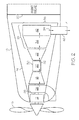
FIG. 2 is a sectional schematic view of the airplane ofFIG. 1 illustrating a gearbox and an exemplary gas turbine engine (a turboprop engine) therein in communication with an embodiment of the bifurcated duct according to exemplary embodiments of the present invention; -
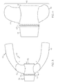
FIG. 3 is a top plan view of an embodiment of the bifurcated duct including a plenum coupled to a pair of exhaust ducts and in communication with the diffuser ofFIG. 2 ; -
FIG. 4 is a top plan view of the plenum of the bifurcated duct ofFIG. 3 , illustrating the plenum in communication with the diffuser; -
FIG. 5 is a bottom plan view of the plenum ofFIG. 4 , illustrating an exemplary generally axi-symmetrical inner body (in dotted lines) that increases in diameter in the aft direction and is disposed in an axial rear end portion of an outer generally cylindrical body that is intersected by a pair of exhaust duct stubs that are configured to be coupled to the pair of exhaust ducts ofFIG. 3 , according to exemplary embodiments of the present invention; -
FIG. 6 is an isometric view of the plenum ofFIGS. 3 through 5 ; and -
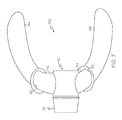
FIG. 7 is a top plan view of an alternative embodiment of the bifurcated duct, illustrating the plenum ofFIGS. 3 through 6 coupled to the pair of exhaust ducts ofFIGS. 3 and5 and defining an air gap therebetween as part of an exhaust eductor system. - The following detailed description is merely exemplary in nature and is not intended to limit the invention or the application and uses of the invention. As used herein, the word "exemplary" means "serving as an example, instance, or illustration." Thus, any embodiment described herein as "exemplary" is not necessarily to be construed as preferred or advantageous over other embodiments. All of the embodiments described herein are exemplary embodiments provided to enable persons skilled in the art to make or use the invention and not to limit the scope of the invention which is defined by the claims. Furthermore, there is no intention to be bound by any expressed or implied theory presented in the preceding technical field, background, brief summary, or the following detailed description.
- Various embodiments are directed to bifurcated ducts including plenums for stabilizing flow therethrough and exhaust systems including the same. The various embodiments provide reduced turbulence, flow separation, and backpressure in the bifurcated ducts, reducing noise and damage to surrounding structures that are normally created by unsteady fluid flow through conventional bifurcated ducts. As used herein, the terms "unitary", "integrally-formed, and "integral" mean a one-piece seamless structure and excludes means for maintaining parts in a fixed relationship as a single unit. The term "bifurcated duct" includes a bifurcated exhaust duct that is used in an exhaust system for a gas turbine engine.
- While the advantages of the present invention as described herein will be described with reference to bifurcated exhaust ducts in exhaust systems for aircraft gas turbine engines, the teachings of the present invention are generally applicable to any bifurcated duct for stabilizing flow therethrough to reduce turbulence, unsteady flow, flow separation, and backpressure therein. Exemplary bifurcated ducts include, but are not limited to, bifurcated water ducts, bifurcated air conditioning ducts, bifurcated automobile ducts, etc. In certain embodiments, the gas turbine engine may be incorporated into an aircraft, a watercraft, a locomotive, a power generation system, or combinations thereof. The gas turbine engine may assume the form of a turbofan, turboprop, turboshaft, turbojet engine, or an auxiliary power unit, to list but a few examples.
- For example,
FIG. 1 depicts anexemplary airplane 10 having a forward portion (FIG. 2 ) that includes an exemplary turbopropgas turbine engine 14 attached to apropeller 16 in a known configuration. The illustratedgas turbine engine 14 ofFIG. 2 includes agearbox 12, anintake section 28, acompressor 18, acombustor section 20, aturbine 22, and anexhaust section 24. Theturbine 22 is drivingly coupled to thecompressor 18 via ashaft 26 oriented along a first longitudinal axis of the gas turbine engine. As indicated by the arrows, air may enter the gas turbine engine through anintake section 28 and flow into thecompressor 18, which compresses the air prior to entry into thecombustor section 20. The illustrated combustor section includes acombustor housing 30 disposed concentrically or annularly about theshaft 26 axially between the compressor and the turbine. The compressed air from thecompressor 18 enters combustors where the compressed air may mix and combust with fuel within the combustors to drive the turbine. From thecombustor section 20, thehot combustion gases 32 flow through theturbine 22, driving the compressor via the shaft. For example, the combustion gases may apply motive forces to turbine rotor blades within theturbine 22 to rotate theshaft 26 that drives thepropeller 16. After flowing through theturbine 22, the hot combustion gases may exit thegas turbine engine 14 through theexhaust section 24. Theexhaust section 24 is located behind theturbine 22 and at the rear of theengine 14. Theairplane 10 may include afirewall 33. - Still referring to
FIG. 2 , theexhaust section 24 includes a diffuser 34 (also shown inFIGS. 3 through 7 ) disposed about the first longitudinal axis downstream from theturbine 22. Thediffuser 34 guides the combustion gases about the shaft along the first longitudinal axis. The volume of thediffuser 34 gradually increases toward a diffuser outlet 36 (e.g.,FIGS. 3 and5 ), thereby gradually increasing the pressure and reducing the airflow speed within the diffuser. At the diffuser outlet 36, the exhaust gas flows into the bifurcated duct 38 (more particularly, into a plenum inlet 40 (FIGS. 3 through 7 ) of aplenum 42 of the bifurcated duct 38).Connector flanges 43 may be used to couple thebifurcated duct 38 to thediffuser 34 as depicted inFIGS. 3 through 7 . The connector flanges are fastened together with fasteners such as bolts or the like. - Referring again to
FIGS. 3 through 7 , according to exemplary embodiments of the present invention, the bifurcatedduct 38 including a bifurcated exhaust duct comprises theplenum 42 and a pair of exhaust ducts (first andsecond exhaust ducts FIGS. 3 and7 ) (also referred to herein as secondary exhaust ducts) coupled thereto. Theplenum 42 channels the exhaust flow (35 inFIG. 2 ) from thegas turbine engine 14 into the first andsecond exhaust ducts 44 or 144 (FIG. 7 ) and 46 or 146 (FIG. 7 ) that discharge theexhaust flow 35 into the atmosphere as hereinafter described and depicted inFIGS. 1 and2 (Asingle exhaust duct 46 on one side of theairplane 10 is depicted inFIGS. 1 and2 ). Theplenum 42 includes the plenum inlet 40 to which the diffuser outlet 36 is fluidly coupled. The initial diameter of theplenum 42 at the plenum inlet 40 is similar or identical to the diameter of the diffuser outlet 36. - Still referring to
FIGS. 3 through 7 , in accordance with exemplary embodiments of the present invention, theplenum 42 of the bifurcatedduct 38 comprises an outercylindrical body 50 intersected by a pair ofexhaust duct stubs exhaust ducts 44/144 and 46/146 and an inner body 56 (shown in dotted lines inFIG. 5 ) disposed in an axial rear end portion of the outercylindrical body 50. The outercylindrical body 50 has a substantially constant outer diameter and includes the axial rear end portion (that is opposite the plenum inlet at an axial front end portion). Theinner body 56 has a diameter that increases in the aft direction as shown inFIG. 5 . An inner surface of the wall of the outer cylindrical body is contoured to include a rounded fillet at the intersection of theexhaust duct stubs cylindrical body 50 for purposes as hereinafter described. For example, the contoured wall may gradually curve around, and diverge from, an outer circumference of the diffuser to define the exhaust duct stubs. The contoured wall of the outercylindrical body 50 reduces low velocity regions and flow separation by eliminating sudden changes in the flow direction (shown by arrows inFIG. 2 ). - While the
inner body 56 is depicted inFIGS. 5 and 6 as being generally axi-symmetrical and having a frustoconical shape, it is to be understood that the inner body may be non-axi-symmetrical and the shape of the inner body having a diameter that increases in the aft direction may be other than frustoconical (e.g., elliptical, hemispherical, conical, etc.). When disposed in the axial rear end portion of the outercylindrical body 50, theinner body 56 decreases the area/volume of the outercylindrical body 50 for purposes as hereinafter described. Theinner body 56 may comprise a hollow body, a solid body, or a substantially solid body. - In one embodiment, the
plenum 42 is a one-piece seamless unitary structure in which the outercylindrical body 50 is integral with theinner body 56 forming a seamless unitary plenum that may be manufactured by a process such as by casting or the like. Thus, in the seamless unitary plenum, theinner body 56 is not removable or separable from the outercylindrical body 50. Alternatively, theplenum 42 comprises a plenum assembly comprising the outercylindrical portion 50 coupled to theinner body 56, such as by a weldment or the like. In still another exemplary embodiment, the entire bifurcated duct (such as a bifurcated exhaust duct) comprises a seamless unitary structure manufactured by a casting process or the like. - The outer
cylindrical body 50 and theinner body 56 may be co-axially disposed about the first longitudinal axis of the gas turbine engine (FIG. 2 ) downstream of thediffuser 34. The pair of exhaust duct stubs comprises a firstexhaust duct stub 52 and a secondexhaust duct stub 54. The first and secondexhaust duct stubs cylindrical body 50. The first and exhaust duct stubs are openended to allow the flow of exhaust gas therethrough. The open end of the firstexhaust duct stub 52 that is spaced apart from the outercylindrical body 50 is configured to be coupled to thefirst exhaust duct 44/144 that leads outside the aircraft. The open end of the secondexhaust duct stub 54 that is spaced apart from the outercylindrical body 30 is configured to be coupled to thesecond exhaust duct 46/146 that also leads outside the aircraft. The first and second exhaust ducts may discharge exhaust flow on opposite sides of the airplane as depicted inFIG. 1 (again, a single exhaust duct is depicted inFIG. 1 ). - In an embodiment, as depicted in
FIG. 3 , the plenum 42 (more particularly, the first and secondexhaust duct stubs 52 and 54) may be coupled to the first andsecond exhaust ducts FIG. 7 , the first and secondexhaust duct stubs plenum 42 are configured to be respectively coupled to the first andsecond exhaust ducts exhaust duct stub 52 and thefirst exhaust duct 144 and asecond air gap 62 between the secondexhaust duct stub 54 and thesecond exhaust duct 146. Thebifurcated duct 138 depicted inFIG. 7 may be part of an exhaust gas eductor system (not shown). The primary purpose of an exhaust gas eductor system is to ventilate the engine compartment by educting compartment air into the exhaust gas flow throughair gaps 60 and 62. Alternatively, if needed, it can be used to educt ambient air throughair gaps 60 and 62 to mix with the hot exhaust gas 35 (FIG. 2 ) so as to reduce the exhaust gas temperature prior to its discharge from the exhaust ducts, with minimum effect on the performance of the engine. - In operation (see, e.g.,
FIG. 2 ), theexhaust gas 35 exits theturbine 22 through thediffuser 34 in theexhaust section 24. As the exhaust gas passes from the exhaust section to theplenum 42 of the bifurcatedduct 38/138 as described herein, the exhaust gas enters the plenum 42 (see, e.g.,FIG. 5 ) where the inner body helps to turn and isolate the flow entering the firstexhaust duct stub 52 from the flow entering secondexhaust duct stub 54. In addition, the inner body helps to provide a nearly constant effective flow area for the exhaust gas as it flows from the diffuser outlet 36 into the first and secondexhaust duct stubs exhaust duct stubs - From the foregoing, it is to be appreciated that the bifurcated ducts including plenums for stabilizing flow therethrough and exhaust systems including the same reduce turbulence, unsteady flow, flow separation, and backpressure in the bifurcated ducts, thereby reducing noise and damage to the engine and surrounding structures that are normally created by unsteady fluid flow through conventional bifurcated ducts.
- In this document, relational terms such as first and second, and the like may be used solely to distinguish one entity or action from another entity or action without necessarily requiring or implying any actual such relationship or order between such entities or actions. Numerical ordinals such as "first," "second," "third," etc. simply denote different singles of a plurality and do not imply any order or sequence unless specifically defined by the claim language. The sequence of the text in any of the claims does not imply that process steps must be performed in a temporal or logical order according to such sequence unless it is specifically defined by the language of the claim. The process steps may be interchanged in any order without departing from the scope of the invention as long as such an interchange does not contradict the claim language and is not logically nonsensical.
- Furthermore, depending on the context, words such as "connect" or "coupled to" used in describing a relationship between different elements do not imply that a direct physical connection must be made between these elements. For example, two elements may be connected to each other physically, electronically, logically, or in any other manner, through one or more additional elements.
- While at least one exemplary embodiment has been presented in the foregoing detailed description of the invention, it should be appreciated that a vast number of variations exist. It should also be appreciated that the exemplary embodiment or exemplary embodiments are only examples, and are not intended to limit the scope, applicability, or configuration of the invention in any way. Rather, the foregoing detailed description will provide those skilled in the art with a convenient road map for implementing an exemplary embodiment of the invention. It being understood that various changes may be made in the function and arrangement of elements described in an exemplary embodiment without departing from the scope of the invention as set forth in the appended claims.
Claims (15)
- A plenum for a bifurcated duct, the plenum comprising:an outer cylindrical body intersected by a pair of exhaust duct stubs that are configured to be coupled to a corresponding pair of exhaust ducts of the bifurcated duct, the outer cylindrical body including an axial rear end portion; andan inner body disposed in the axial rear end portion and that increases in diameter in the aft direction, the inner body comprising one of a generally axi-symmetrical inner body or a non-axi-symmetrical inner body.
- The plenum of Claim 1, wherein the inner body and the outer cylindrical body cooperate to form the plenum comprising a seamless unitary plenum.
- The plenum of Claim 1, wherein the inner body is coupled to the outer cylindrical body to form the plenum comprising a plenum assembly.
- The plenum of Claim 1, wherein the outer cylindrical body and the inner body are co-axially disposed.
- The plenum of Claim 1, wherein the generally axi-symmetrical inner body is selected from the group consisting of a generally conical body, a generally elliptical body, a generally frustoconical body, and a generally hemispherical body.
- The plenum of Claim 1, wherein the plenum is configured to be disposed between a diffuser in an exhaust section of a gas turbine engine and the pair of exhaust ducts.
- The plenum of Claim 1, wherein an inner surface of the outer cylindrical body is contoured to define a rounded fillet where intersected by the pair of exhaust duct stubs.
- The plenum of Claim 1, wherein the inner body comprises one of a hollow body, a solid body, or a substantially solid body.
- The bifurcated duct of Claim 1, wherein the pair of exhaust duct stubs comprises a first exhaust duct stub and a second exhaust duct stub and the pair of exhaust ducts comprises a first exhaust duct and a second exhaust duct, the first exhaust duct stub coupled to the first exhaust duct and the second exhaust duct stub coupled to the second exhaust duct.
- The bifurcated duct of Claim 9, wherein the first exhaust duct stub is coupled to the first exhaust duct with a first air gap therebetween and the second exhaust duct stub is coupled to the second exhaust duct with a second air gap therebetween to define a part of an exhaust eductor system.
- The bifurcated duct of Claim 1, wherein the bifurcated duct comprises a bifurcated exhaust duct for a gas turbine engine.
- An exhaust system for an aircraft comprising:a gas turbine engine comprising an exhaust section including a diffuser; anda bifurcated exhaust duct in communication with the diffuser, the bifurcated exhaust duct comprising:a plenum comprising:an outer cylindrical body intersected by a pair of exhaust duct stubs, the outer cylindrical body including an axial rear end portion; andan inner body disposed in the axial rear end portion, that increases in diameter in the aft direction, and comprises one of a generally axi-symmetrical inner body or a non-axi-symmetrical inner body;anda pair of exhaust ducts in fluid communication with the pair of exhaust duct stubs.
- The exhaust system of Claim 12, wherein the bifurcated exhaust duct comprises a seamless unitary structure.
- The exhaust system of Claim 12, wherein the plenum comprises a seamless unitary plenum or a plenum assembly comprising the inner body coupled to the outer cylindrical body.
- The exhaust system of Claim 12, wherein the pair of exhaust duct stubs comprises a first exhaust duct stub and a second exhaust duct stub and the pair of exhaust ducts comprises a first exhaust duct and a second exhaust duct, the first exhaust duct stub coupled to the first exhaust duct with a first air gap therebetween and the second exhaust duct stub coupled to the second exhaust duct with a second air gap therebetween to define a part of an exhaust eductor system of the gas turbine engine.
Applications Claiming Priority (1)
| Application Number | Priority Date | Filing Date | Title |
|---|---|---|---|
| US14/174,422 US9969500B2 (en) | 2014-02-06 | 2014-02-06 | Bifurcated ducts including plenums for stabilizing flow therethrough and exhaust systems including the same |
Publications (2)
| Publication Number | Publication Date |
|---|---|
| EP2905227A1 true EP2905227A1 (en) | 2015-08-12 |
| EP2905227B1 EP2905227B1 (en) | 2019-03-20 |
Family
ID=52432669
Family Applications (1)
| Application Number | Title | Priority Date | Filing Date |
|---|---|---|---|
| EP15152396.6A Active EP2905227B1 (en) | 2014-02-06 | 2015-01-23 | Bifurcated ducts including plenums for stabilizing flow therethrough and exhaust systems including the same |
Country Status (2)
| Country | Link |
|---|---|
| US (1) | US9969500B2 (en) |
| EP (1) | EP2905227B1 (en) |
Cited By (1)
| Publication number | Priority date | Publication date | Assignee | Title |
|---|---|---|---|---|
| EP3418507A1 (en) * | 2017-06-19 | 2018-12-26 | General Electric Company Polska Sp. Z o.o | Exhaust assembly with vortex generator |
Families Citing this family (4)
| Publication number | Priority date | Publication date | Assignee | Title |
|---|---|---|---|---|
| US10415502B2 (en) | 2017-09-11 | 2019-09-17 | Honeywell International Inc. | Swirling flow eductor system and method |
| KR20210090501A (en) * | 2020-01-10 | 2021-07-20 | 한화에어로스페이스 주식회사 | Exhaust duct and exhaust duct assembly and aircraft using the exhaust duct |
| KR20220093987A (en) | 2020-12-28 | 2022-07-05 | 한화에어로스페이스 주식회사 | An exhaust duct assembly with an improved weld zone structure and aircraft including the same |
| US11952962B1 (en) | 2023-01-31 | 2024-04-09 | Pratt & Whitney Canada Corp. | Exhaust duct for gas turbine engine |
Citations (6)
| Publication number | Priority date | Publication date | Assignee | Title |
|---|---|---|---|---|
| US3164337A (en) * | 1959-09-29 | 1965-01-05 | Hawker Aircraft Ltd | Jet aircraft with orientable nozzles for vertical or forward movement |
| US3191886A (en) * | 1957-01-29 | 1965-06-29 | Bristol Siddeley Engines Ltd | Gas turbine jet propulsion engine units for aircraft and also jet propelled aircraft |
| US3388550A (en) * | 1966-11-14 | 1968-06-18 | United Aircraft Canada | Turbine engine exhaust duct |
| US3614037A (en) * | 1969-09-22 | 1971-10-19 | Boeing Co | Aircraft combination thrust reverser and sound suppressor and a particular full range balanced thrust reverser |
| WO1999054204A1 (en) * | 1998-04-22 | 1999-10-28 | Pratt & Whitney Canada Corp | Jet engine exhaust nozzle |
| US7967219B1 (en) * | 1979-01-12 | 2011-06-28 | Rolls-Royce Limited | Thrust nozzle for a gas turbine engine |
Family Cites Families (8)
| Publication number | Priority date | Publication date | Assignee | Title |
|---|---|---|---|---|
| BE500180A (en) * | 1949-12-31 | |||
| GB899862A (en) | 1959-10-30 | 1962-06-27 | Hawker Aircraft Ltd | Improvements in aircraft control mechanism |
| US3290877A (en) * | 1964-12-14 | 1966-12-13 | United Aircraft Canada | Turbine engine exhaust arrangement |
| FR2787513B1 (en) | 1998-12-17 | 2001-01-19 | Turbomeca | MULTICHANNEL EXHAUST DEVICE FOR ACOUSTICALLY TREATED TURBOMACHINE |
| US6988674B2 (en) | 2004-06-08 | 2006-01-24 | General Electric Company | Method and apparatus for suppressing infrared signatures |
| EP1975372A1 (en) * | 2007-03-28 | 2008-10-01 | Siemens Aktiengesellschaft | Eccentric chamfer at inlet of branches in a flow channel |
| GB0814314D0 (en) * | 2008-08-06 | 2008-09-10 | Rolls Royce Plc | A Method of assembling a multi-stage turbine or compressor |
| US9366190B2 (en) * | 2013-05-13 | 2016-06-14 | Solar Turbines Incorporated | Tapered gas turbine engine liquid gallery |
-
2014
- 2014-02-06 US US14/174,422 patent/US9969500B2/en active Active
-
2015
- 2015-01-23 EP EP15152396.6A patent/EP2905227B1/en active Active
Patent Citations (6)
| Publication number | Priority date | Publication date | Assignee | Title |
|---|---|---|---|---|
| US3191886A (en) * | 1957-01-29 | 1965-06-29 | Bristol Siddeley Engines Ltd | Gas turbine jet propulsion engine units for aircraft and also jet propelled aircraft |
| US3164337A (en) * | 1959-09-29 | 1965-01-05 | Hawker Aircraft Ltd | Jet aircraft with orientable nozzles for vertical or forward movement |
| US3388550A (en) * | 1966-11-14 | 1968-06-18 | United Aircraft Canada | Turbine engine exhaust duct |
| US3614037A (en) * | 1969-09-22 | 1971-10-19 | Boeing Co | Aircraft combination thrust reverser and sound suppressor and a particular full range balanced thrust reverser |
| US7967219B1 (en) * | 1979-01-12 | 2011-06-28 | Rolls-Royce Limited | Thrust nozzle for a gas turbine engine |
| WO1999054204A1 (en) * | 1998-04-22 | 1999-10-28 | Pratt & Whitney Canada Corp | Jet engine exhaust nozzle |
Cited By (1)
| Publication number | Priority date | Publication date | Assignee | Title |
|---|---|---|---|---|
| EP3418507A1 (en) * | 2017-06-19 | 2018-12-26 | General Electric Company Polska Sp. Z o.o | Exhaust assembly with vortex generator |
Also Published As
| Publication number | Publication date |
|---|---|
| US9969500B2 (en) | 2018-05-15 |
| US20150218967A1 (en) | 2015-08-06 |
| EP2905227B1 (en) | 2019-03-20 |
Similar Documents
| Publication | Publication Date | Title |
|---|---|---|
| US8186942B2 (en) | Nacelle assembly with turbulators | |
| EP2905227B1 (en) | Bifurcated ducts including plenums for stabilizing flow therethrough and exhaust systems including the same | |
| EP2659119B1 (en) | Gas turbine engine with bypass mixer | |
| US10920713B2 (en) | Compression cowl for jet engine exhaust | |
| US10352274B2 (en) | Direct drive aft fan engine | |
| EP1998027A2 (en) | Gas turbine engine comprising a nacelle compartment plenum for bleed air flow delivery system | |
| US11415079B2 (en) | Turbo-shaft ejector with flow guide ring | |
| US10308368B2 (en) | Turbofan engine and method of reducing air flow separation therein | |
| US4696159A (en) | Gas turbine outlet arrangement | |
| CN110691942A (en) | Trapped vortex combustor for gas turbine engine with driver airflow path | |
| EP1809893B1 (en) | Stator for a jet engine, a jet engine comprising such a stator, and an aircraft comprising the jet engine | |
| JP2017115857A (en) | Fan case for use in turbofan engine, and method of assembling turbofan engine | |
| US10184372B2 (en) | Exhaust systems and methods for gas turbine engine | |
| US11732645B2 (en) | Bleed air offtake assembly for a gas turbine engine | |
| US20140174094A1 (en) | APU Exhaust Housing Perforated Ring | |
| US11920539B1 (en) | Gas turbine exhaust nozzle noise abatement | |
| US11781504B2 (en) | Bleed plenum for compressor section |
Legal Events
| Date | Code | Title | Description |
|---|---|---|---|
| PUAI | Public reference made under article 153(3) epc to a published international application that has entered the european phase |
Free format text: ORIGINAL CODE: 0009012 |
|
| 17P | Request for examination filed |
Effective date: 20150123 |
|
| AK | Designated contracting states |
Kind code of ref document: A1 Designated state(s): AL AT BE BG CH CY CZ DE DK EE ES FI FR GB GR HR HU IE IS IT LI LT LU LV MC MK MT NL NO PL PT RO RS SE SI SK SM TR |
|
| AX | Request for extension of the european patent |
Extension state: BA ME |
|
| RAP1 | Party data changed (applicant data changed or rights of an application transferred) |
Owner name: HONEYWELL INTERNATIONAL INC. |
|
| STAA | Information on the status of an ep patent application or granted ep patent |
Free format text: STATUS: EXAMINATION IS IN PROGRESS |
|
| 17Q | First examination report despatched |
Effective date: 20171214 |
|
| GRAP | Despatch of communication of intention to grant a patent |
Free format text: ORIGINAL CODE: EPIDOSNIGR1 |
|
| STAA | Information on the status of an ep patent application or granted ep patent |
Free format text: STATUS: GRANT OF PATENT IS INTENDED |
|
| INTG | Intention to grant announced |
Effective date: 20181031 |
|
| GRAS | Grant fee paid |
Free format text: ORIGINAL CODE: EPIDOSNIGR3 |
|
| GRAA | (expected) grant |
Free format text: ORIGINAL CODE: 0009210 |
|
| STAA | Information on the status of an ep patent application or granted ep patent |
Free format text: STATUS: THE PATENT HAS BEEN GRANTED |
|
| AK | Designated contracting states |
Kind code of ref document: B1 Designated state(s): AL AT BE BG CH CY CZ DE DK EE ES FI FR GB GR HR HU IE IS IT LI LT LU LV MC MK MT NL NO PL PT RO RS SE SI SK SM TR |
|
| REG | Reference to a national code |
Ref country code: GB Ref legal event code: FG4D |
|
| REG | Reference to a national code |
Ref country code: CH Ref legal event code: EP |
|
| REG | Reference to a national code |
Ref country code: DE Ref legal event code: R096 Ref document number: 602015026622 Country of ref document: DE |
|
| REG | Reference to a national code |
Ref country code: AT Ref legal event code: REF Ref document number: 1110273 Country of ref document: AT Kind code of ref document: T Effective date: 20190415 |
|
| REG | Reference to a national code |
Ref country code: IE Ref legal event code: FG4D |
|
| REG | Reference to a national code |
Ref country code: NL Ref legal event code: MP Effective date: 20190320 |
|
| PG25 | Lapsed in a contracting state [announced via postgrant information from national office to epo] |
Ref country code: LT Free format text: LAPSE BECAUSE OF FAILURE TO SUBMIT A TRANSLATION OF THE DESCRIPTION OR TO PAY THE FEE WITHIN THE PRESCRIBED TIME-LIMIT Effective date: 20190320 Ref country code: FI Free format text: LAPSE BECAUSE OF FAILURE TO SUBMIT A TRANSLATION OF THE DESCRIPTION OR TO PAY THE FEE WITHIN THE PRESCRIBED TIME-LIMIT Effective date: 20190320 Ref country code: NO Free format text: LAPSE BECAUSE OF FAILURE TO SUBMIT A TRANSLATION OF THE DESCRIPTION OR TO PAY THE FEE WITHIN THE PRESCRIBED TIME-LIMIT Effective date: 20190620 Ref country code: SE Free format text: LAPSE BECAUSE OF FAILURE TO SUBMIT A TRANSLATION OF THE DESCRIPTION OR TO PAY THE FEE WITHIN THE PRESCRIBED TIME-LIMIT Effective date: 20190320 |
|
| REG | Reference to a national code |
Ref country code: LT Ref legal event code: MG4D |
|
| PG25 | Lapsed in a contracting state [announced via postgrant information from national office to epo] |
Ref country code: GR Free format text: LAPSE BECAUSE OF FAILURE TO SUBMIT A TRANSLATION OF THE DESCRIPTION OR TO PAY THE FEE WITHIN THE PRESCRIBED TIME-LIMIT Effective date: 20190621 Ref country code: BG Free format text: LAPSE BECAUSE OF FAILURE TO SUBMIT A TRANSLATION OF THE DESCRIPTION OR TO PAY THE FEE WITHIN THE PRESCRIBED TIME-LIMIT Effective date: 20190620 Ref country code: LV Free format text: LAPSE BECAUSE OF FAILURE TO SUBMIT A TRANSLATION OF THE DESCRIPTION OR TO PAY THE FEE WITHIN THE PRESCRIBED TIME-LIMIT Effective date: 20190320 Ref country code: HR Free format text: LAPSE BECAUSE OF FAILURE TO SUBMIT A TRANSLATION OF THE DESCRIPTION OR TO PAY THE FEE WITHIN THE PRESCRIBED TIME-LIMIT Effective date: 20190320 Ref country code: NL Free format text: LAPSE BECAUSE OF FAILURE TO SUBMIT A TRANSLATION OF THE DESCRIPTION OR TO PAY THE FEE WITHIN THE PRESCRIBED TIME-LIMIT Effective date: 20190320 Ref country code: RS Free format text: LAPSE BECAUSE OF FAILURE TO SUBMIT A TRANSLATION OF THE DESCRIPTION OR TO PAY THE FEE WITHIN THE PRESCRIBED TIME-LIMIT Effective date: 20190320 |
|
| REG | Reference to a national code |
Ref country code: AT Ref legal event code: MK05 Ref document number: 1110273 Country of ref document: AT Kind code of ref document: T Effective date: 20190320 |
|
| PG25 | Lapsed in a contracting state [announced via postgrant information from national office to epo] |
Ref country code: SK Free format text: LAPSE BECAUSE OF FAILURE TO SUBMIT A TRANSLATION OF THE DESCRIPTION OR TO PAY THE FEE WITHIN THE PRESCRIBED TIME-LIMIT Effective date: 20190320 Ref country code: IT Free format text: LAPSE BECAUSE OF FAILURE TO SUBMIT A TRANSLATION OF THE DESCRIPTION OR TO PAY THE FEE WITHIN THE PRESCRIBED TIME-LIMIT Effective date: 20190320 Ref country code: EE Free format text: LAPSE BECAUSE OF FAILURE TO SUBMIT A TRANSLATION OF THE DESCRIPTION OR TO PAY THE FEE WITHIN THE PRESCRIBED TIME-LIMIT Effective date: 20190320 Ref country code: RO Free format text: LAPSE BECAUSE OF FAILURE TO SUBMIT A TRANSLATION OF THE DESCRIPTION OR TO PAY THE FEE WITHIN THE PRESCRIBED TIME-LIMIT Effective date: 20190320 Ref country code: CZ Free format text: LAPSE BECAUSE OF FAILURE TO SUBMIT A TRANSLATION OF THE DESCRIPTION OR TO PAY THE FEE WITHIN THE PRESCRIBED TIME-LIMIT Effective date: 20190320 Ref country code: ES Free format text: LAPSE BECAUSE OF FAILURE TO SUBMIT A TRANSLATION OF THE DESCRIPTION OR TO PAY THE FEE WITHIN THE PRESCRIBED TIME-LIMIT Effective date: 20190320 Ref country code: AL Free format text: LAPSE BECAUSE OF FAILURE TO SUBMIT A TRANSLATION OF THE DESCRIPTION OR TO PAY THE FEE WITHIN THE PRESCRIBED TIME-LIMIT Effective date: 20190320 Ref country code: PT Free format text: LAPSE BECAUSE OF FAILURE TO SUBMIT A TRANSLATION OF THE DESCRIPTION OR TO PAY THE FEE WITHIN THE PRESCRIBED TIME-LIMIT Effective date: 20190720 |
|
| PG25 | Lapsed in a contracting state [announced via postgrant information from national office to epo] |
Ref country code: PL Free format text: LAPSE BECAUSE OF FAILURE TO SUBMIT A TRANSLATION OF THE DESCRIPTION OR TO PAY THE FEE WITHIN THE PRESCRIBED TIME-LIMIT Effective date: 20190320 Ref country code: SM Free format text: LAPSE BECAUSE OF FAILURE TO SUBMIT A TRANSLATION OF THE DESCRIPTION OR TO PAY THE FEE WITHIN THE PRESCRIBED TIME-LIMIT Effective date: 20190320 |
|
| PG25 | Lapsed in a contracting state [announced via postgrant information from national office to epo] |
Ref country code: AT Free format text: LAPSE BECAUSE OF FAILURE TO SUBMIT A TRANSLATION OF THE DESCRIPTION OR TO PAY THE FEE WITHIN THE PRESCRIBED TIME-LIMIT Effective date: 20190320 Ref country code: IS Free format text: LAPSE BECAUSE OF FAILURE TO SUBMIT A TRANSLATION OF THE DESCRIPTION OR TO PAY THE FEE WITHIN THE PRESCRIBED TIME-LIMIT Effective date: 20190720 |
|
| REG | Reference to a national code |
Ref country code: DE Ref legal event code: R097 Ref document number: 602015026622 Country of ref document: DE |
|
| PLBE | No opposition filed within time limit |
Free format text: ORIGINAL CODE: 0009261 |
|
| STAA | Information on the status of an ep patent application or granted ep patent |
Free format text: STATUS: NO OPPOSITION FILED WITHIN TIME LIMIT |
|
| PG25 | Lapsed in a contracting state [announced via postgrant information from national office to epo] |
Ref country code: DK Free format text: LAPSE BECAUSE OF FAILURE TO SUBMIT A TRANSLATION OF THE DESCRIPTION OR TO PAY THE FEE WITHIN THE PRESCRIBED TIME-LIMIT Effective date: 20190320 |
|
| 26N | No opposition filed |
Effective date: 20200102 |
|
| PG25 | Lapsed in a contracting state [announced via postgrant information from national office to epo] |
Ref country code: SI Free format text: LAPSE BECAUSE OF FAILURE TO SUBMIT A TRANSLATION OF THE DESCRIPTION OR TO PAY THE FEE WITHIN THE PRESCRIBED TIME-LIMIT Effective date: 20190320 |
|
| PG25 | Lapsed in a contracting state [announced via postgrant information from national office to epo] |
Ref country code: TR Free format text: LAPSE BECAUSE OF FAILURE TO SUBMIT A TRANSLATION OF THE DESCRIPTION OR TO PAY THE FEE WITHIN THE PRESCRIBED TIME-LIMIT Effective date: 20190320 |
|
| PG25 | Lapsed in a contracting state [announced via postgrant information from national office to epo] |
Ref country code: MC Free format text: LAPSE BECAUSE OF FAILURE TO SUBMIT A TRANSLATION OF THE DESCRIPTION OR TO PAY THE FEE WITHIN THE PRESCRIBED TIME-LIMIT Effective date: 20190320 |
|
| REG | Reference to a national code |
Ref country code: CH Ref legal event code: PL |
|
| GBPC | Gb: european patent ceased through non-payment of renewal fee |
Effective date: 20200123 |
|
| REG | Reference to a national code |
Ref country code: BE Ref legal event code: MM Effective date: 20200131 |
|
| PG25 | Lapsed in a contracting state [announced via postgrant information from national office to epo] |
Ref country code: FR Free format text: LAPSE BECAUSE OF NON-PAYMENT OF DUE FEES Effective date: 20200131 Ref country code: LU Free format text: LAPSE BECAUSE OF NON-PAYMENT OF DUE FEES Effective date: 20200123 Ref country code: GB Free format text: LAPSE BECAUSE OF NON-PAYMENT OF DUE FEES Effective date: 20200123 |
|
| PG25 | Lapsed in a contracting state [announced via postgrant information from national office to epo] |
Ref country code: CH Free format text: LAPSE BECAUSE OF NON-PAYMENT OF DUE FEES Effective date: 20200131 Ref country code: LI Free format text: LAPSE BECAUSE OF NON-PAYMENT OF DUE FEES Effective date: 20200131 Ref country code: BE Free format text: LAPSE BECAUSE OF NON-PAYMENT OF DUE FEES Effective date: 20200131 |
|
| PG25 | Lapsed in a contracting state [announced via postgrant information from national office to epo] |
Ref country code: IE Free format text: LAPSE BECAUSE OF NON-PAYMENT OF DUE FEES Effective date: 20200123 |
|
| PG25 | Lapsed in a contracting state [announced via postgrant information from national office to epo] |
Ref country code: MT Free format text: LAPSE BECAUSE OF FAILURE TO SUBMIT A TRANSLATION OF THE DESCRIPTION OR TO PAY THE FEE WITHIN THE PRESCRIBED TIME-LIMIT Effective date: 20190320 Ref country code: CY Free format text: LAPSE BECAUSE OF FAILURE TO SUBMIT A TRANSLATION OF THE DESCRIPTION OR TO PAY THE FEE WITHIN THE PRESCRIBED TIME-LIMIT Effective date: 20190320 |
|
| PG25 | Lapsed in a contracting state [announced via postgrant information from national office to epo] |
Ref country code: MK Free format text: LAPSE BECAUSE OF FAILURE TO SUBMIT A TRANSLATION OF THE DESCRIPTION OR TO PAY THE FEE WITHIN THE PRESCRIBED TIME-LIMIT Effective date: 20190320 |
|
| PGFP | Annual fee paid to national office [announced via postgrant information from national office to epo] |
Ref country code: DE Payment date: 20230127 Year of fee payment: 9 |
|
| P01 | Opt-out of the competence of the unified patent court (upc) registered |
Effective date: 20230525 |