EP3795475B1 - Séparateur de particules à inertie pour moteur d'aéronef - Google Patents
Séparateur de particules à inertie pour moteur d'aéronef Download PDFInfo
- Publication number
- EP3795475B1 EP3795475B1 EP20196673.6A EP20196673A EP3795475B1 EP 3795475 B1 EP3795475 B1 EP 3795475B1 EP 20196673 A EP20196673 A EP 20196673A EP 3795475 B1 EP3795475 B1 EP 3795475B1
- Authority
- EP
- European Patent Office
- Prior art keywords
- duct
- aircraft engine
- channel
- splitter
- engine
- Prior art date
- Legal status (The legal status is an assumption and is not a legal conclusion. Google has not performed a legal analysis and makes no representation as to the accuracy of the status listed.)
- Active
Links
- 239000002245 particle Substances 0.000 title claims description 24
- 239000012080 ambient air Substances 0.000 claims description 12
- 238000011144 upstream manufacturing Methods 0.000 claims description 11
- 238000004891 communication Methods 0.000 claims description 6
- 238000013213 extrapolation Methods 0.000 claims description 5
- 239000012530 fluid Substances 0.000 claims description 5
- 238000000034 method Methods 0.000 claims description 3
- 239000011248 coating agent Substances 0.000 claims description 2
- 238000000576 coating method Methods 0.000 claims description 2
- 239000003570 air Substances 0.000 description 11
- 238000000926 separation method Methods 0.000 description 10
- 239000007789 gas Substances 0.000 description 8
- 239000000463 material Substances 0.000 description 3
- 239000000567 combustion gas Substances 0.000 description 2
- 238000013461 design Methods 0.000 description 2
- 239000000446 fuel Substances 0.000 description 2
- 238000012986 modification Methods 0.000 description 2
- 230000004048 modification Effects 0.000 description 2
- 230000008602 contraction Effects 0.000 description 1
- 230000003247 decreasing effect Effects 0.000 description 1
- 230000001419 dependent effect Effects 0.000 description 1
- 230000000694 effects Effects 0.000 description 1
- 230000037406 food intake Effects 0.000 description 1
- 210000003734 kidney Anatomy 0.000 description 1
- 235000015250 liver sausages Nutrition 0.000 description 1
- 238000012552 review Methods 0.000 description 1
- 230000007704 transition Effects 0.000 description 1
- XLYOFNOQVPJJNP-UHFFFAOYSA-N water Substances O XLYOFNOQVPJJNP-UHFFFAOYSA-N 0.000 description 1
Images


Classifications
-
- B—PERFORMING OPERATIONS; TRANSPORTING
- B64—AIRCRAFT; AVIATION; COSMONAUTICS
- B64D—EQUIPMENT FOR FITTING IN OR TO AIRCRAFT; FLIGHT SUITS; PARACHUTES; ARRANGEMENT OR MOUNTING OF POWER PLANTS OR PROPULSION TRANSMISSIONS IN AIRCRAFT
- B64D33/00—Arrangements in aircraft of power plant parts or auxiliaries not otherwise provided for
- B64D33/02—Arrangements in aircraft of power plant parts or auxiliaries not otherwise provided for of combustion air intakes
-
- F—MECHANICAL ENGINEERING; LIGHTING; HEATING; WEAPONS; BLASTING
- F02—COMBUSTION ENGINES; HOT-GAS OR COMBUSTION-PRODUCT ENGINE PLANTS
- F02C—GAS-TURBINE PLANTS; AIR INTAKES FOR JET-PROPULSION PLANTS; CONTROLLING FUEL SUPPLY IN AIR-BREATHING JET-PROPULSION PLANTS
- F02C7/00—Features, components parts, details or accessories, not provided for in, or of interest apart form groups F02C1/00 - F02C6/00; Air intakes for jet-propulsion plants
- F02C7/04—Air intakes for gas-turbine plants or jet-propulsion plants
- F02C7/042—Air intakes for gas-turbine plants or jet-propulsion plants having variable geometry
-
- F—MECHANICAL ENGINEERING; LIGHTING; HEATING; WEAPONS; BLASTING
- F02—COMBUSTION ENGINES; HOT-GAS OR COMBUSTION-PRODUCT ENGINE PLANTS
- F02C—GAS-TURBINE PLANTS; AIR INTAKES FOR JET-PROPULSION PLANTS; CONTROLLING FUEL SUPPLY IN AIR-BREATHING JET-PROPULSION PLANTS
- F02C7/00—Features, components parts, details or accessories, not provided for in, or of interest apart form groups F02C1/00 - F02C6/00; Air intakes for jet-propulsion plants
- F02C7/04—Air intakes for gas-turbine plants or jet-propulsion plants
- F02C7/05—Air intakes for gas-turbine plants or jet-propulsion plants having provisions for obviating the penetration of damaging objects or particles
- F02C7/052—Air intakes for gas-turbine plants or jet-propulsion plants having provisions for obviating the penetration of damaging objects or particles with dust-separation devices
-
- F—MECHANICAL ENGINEERING; LIGHTING; HEATING; WEAPONS; BLASTING
- F02—COMBUSTION ENGINES; HOT-GAS OR COMBUSTION-PRODUCT ENGINE PLANTS
- F02C—GAS-TURBINE PLANTS; AIR INTAKES FOR JET-PROPULSION PLANTS; CONTROLLING FUEL SUPPLY IN AIR-BREATHING JET-PROPULSION PLANTS
- F02C7/00—Features, components parts, details or accessories, not provided for in, or of interest apart form groups F02C1/00 - F02C6/00; Air intakes for jet-propulsion plants
- F02C7/04—Air intakes for gas-turbine plants or jet-propulsion plants
- F02C7/05—Air intakes for gas-turbine plants or jet-propulsion plants having provisions for obviating the penetration of damaging objects or particles
- F02C7/055—Air intakes for gas-turbine plants or jet-propulsion plants having provisions for obviating the penetration of damaging objects or particles with intake grids, screens or guards
-
- B—PERFORMING OPERATIONS; TRANSPORTING
- B01—PHYSICAL OR CHEMICAL PROCESSES OR APPARATUS IN GENERAL
- B01D—SEPARATION
- B01D45/00—Separating dispersed particles from gases or vapours by gravity, inertia, or centrifugal forces
- B01D45/04—Separating dispersed particles from gases or vapours by gravity, inertia, or centrifugal forces by utilising inertia
-
- B—PERFORMING OPERATIONS; TRANSPORTING
- B64—AIRCRAFT; AVIATION; COSMONAUTICS
- B64D—EQUIPMENT FOR FITTING IN OR TO AIRCRAFT; FLIGHT SUITS; PARACHUTES; ARRANGEMENT OR MOUNTING OF POWER PLANTS OR PROPULSION TRANSMISSIONS IN AIRCRAFT
- B64D33/00—Arrangements in aircraft of power plant parts or auxiliaries not otherwise provided for
- B64D33/02—Arrangements in aircraft of power plant parts or auxiliaries not otherwise provided for of combustion air intakes
- B64D2033/022—Arrangements in aircraft of power plant parts or auxiliaries not otherwise provided for of combustion air intakes comprising bird or foreign object protections
-
- B—PERFORMING OPERATIONS; TRANSPORTING
- B64—AIRCRAFT; AVIATION; COSMONAUTICS
- B64D—EQUIPMENT FOR FITTING IN OR TO AIRCRAFT; FLIGHT SUITS; PARACHUTES; ARRANGEMENT OR MOUNTING OF POWER PLANTS OR PROPULSION TRANSMISSIONS IN AIRCRAFT
- B64D33/00—Arrangements in aircraft of power plant parts or auxiliaries not otherwise provided for
- B64D33/02—Arrangements in aircraft of power plant parts or auxiliaries not otherwise provided for of combustion air intakes
- B64D2033/0246—Arrangements in aircraft of power plant parts or auxiliaries not otherwise provided for of combustion air intakes comprising particle separators
-
- F—MECHANICAL ENGINEERING; LIGHTING; HEATING; WEAPONS; BLASTING
- F05—INDEXING SCHEMES RELATING TO ENGINES OR PUMPS IN VARIOUS SUBCLASSES OF CLASSES F01-F04
- F05D—INDEXING SCHEME FOR ASPECTS RELATING TO NON-POSITIVE-DISPLACEMENT MACHINES OR ENGINES, GAS-TURBINES OR JET-PROPULSION PLANTS
- F05D2260/00—Function
- F05D2260/60—Fluid transfer
- F05D2260/607—Preventing clogging or obstruction of flow paths by dirt, dust, or foreign particles
-
- Y—GENERAL TAGGING OF NEW TECHNOLOGICAL DEVELOPMENTS; GENERAL TAGGING OF CROSS-SECTIONAL TECHNOLOGIES SPANNING OVER SEVERAL SECTIONS OF THE IPC; TECHNICAL SUBJECTS COVERED BY FORMER USPC CROSS-REFERENCE ART COLLECTIONS [XRACs] AND DIGESTS
- Y02—TECHNOLOGIES OR APPLICATIONS FOR MITIGATION OR ADAPTATION AGAINST CLIMATE CHANGE
- Y02T—CLIMATE CHANGE MITIGATION TECHNOLOGIES RELATED TO TRANSPORTATION
- Y02T50/00—Aeronautics or air transport
- Y02T50/60—Efficient propulsion technologies, e.g. for aircraft
Definitions
- Aircraft intake is designed to deliver ambient air flow to engine. It is typically designed to supply air from an environment E outside the engine 10 to the engine while minimizing pressure loss of the air circulating through the intake in different ambient weather conditions to minimize engine fuel consumption. In the meantime, the intake air flow should have less distortion and low swirl at entry of the compressor 14, also referred to as compressor face or engine inlet, before entering the engine to have large surge margin.
- the intake is configured to bypass a large amount of icing particles directly back and out to the environment E to avoid engine flame out.
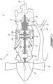
- an ambient air flow F entering the inlet duct 42 of the IPS 40 via the intake 48 splits into two streams F1, F2 one to engine and another to bypass.
- the location of the splitter 50 influences separation efficiency and loss. When its position is more upstream relative to the flow F, the particles are less likely to go to the intermediate duct 44 because the engine entrance duct area is reduced. In such a case, the separation efficiency is better but the pressure loss becomes worse.
- a flat icing screen may be mounted at the splitter 50. In the icing condition, the screen becomes iced up and clogged, resulting in higher separation efficiency.
- aerodynamic losses imparted on the flow F1 to the engine 10 when passing around the clogged screen are non-negligible. The pressure loss may surge due to the flow sudden contraction and expansion around the clogged sheet. This might induce high flow distortion and swirl, which are nondesirable.
- a splitter vane 52 is located within the intermediate duct 44.
- the splitter vane 52 has a leading edge 52a located upstream of the splitter 50 relative to the flow F circulating in the inlet duct 42.
- the splitter vane 52 may have an aerodynamically-shaped profile. In the embodiment shown, the splitter vane 52 has a symmetric airfoil, but any suitable airfoil may be used.
- the splitter vane 52 may be secured within the intermediate duct 44 via side wall portions of said duct 44 connecting the upstream wall portion 44u to the downstream wall portion 44d. Any suitable way of securing the splitter vane 52 within the intermediate duct 44 is contemplated.
- the splitter vane 52 is located between the upstream and downstream wall portions 44u, 44d of the intermediate duct 44.
- the leading edge 52a of the splitter vane 52 may be located radially outwardly of the intersection 50 between the intermediate duct 44 and the bypass duct.
- the leading edge 52a of the splitter vane 52 may be located radially inwardly of the intersection 50.
- a radial distance between the central axis 20 and the leading edge 52a of the splitter vane 52 is greater than that between the central axis 20 and the splitter 50.
- the leading edge 52a of the splitter vane 52 is located upstream of the intersection 50 relative to the flow F.
- a channel 60 is defined between the splitter vane 52 and the downstream wall portion 44d of the intermediate duct 44.
- the plate 62 includes or is constituted by a screen (e.g. mesh material).
- a typical screen is made of wires having a diameter of 0.15 to 3.5 millimetres, preferably 0.6 mm and distanced from one another by a distance of 0.5 to 12 millimetres, preferably 6 mm. Other dimensions are also possible.
- the plate 62 can be configured as a perforated plate, or be defined in part or in whole by open cell material such as honeycomb material.
- the openings may be circular, square, rectangular, elliptical and any other suitable shape.
- a ratio of a total surface area of the openings over a surface area of the plate 62 ranges from about 50% to about 90%. Other configurations are also possible.
- the channel 60 becomes ice-blocked or clogged by ice and all the air that reaches the engine inlet 12 circulates through the intermediate duct 44 between the upstream wall portion 44u and the splitter vane 52.
- the cross-sectional area of the intermediate duct in which engine inlet flow can circulate is less, and the separation efficiency of the IPS 40 is greater, than what they would be if the channel 60 were not clogged by ice.
- the channel 60 is open and air can pass through the plate 62.
- the splitting location moves downstream of the leading edge 52a of the splitter vane 52 and corresponds to the intersection 50 between the downstream wall portion 44d of the intermediate duct 44 and the engine side 46a of the wall of the bypass duct 46. Therefore, the cross-sectional area of the intermediate duct in which air can circulate is increased compared to that in the icing conditions and pressure loss is decreased compared to that in the icing conditions.
- the opening of the channel 60 in non-icing conditions increases the flow area and therefore may decrease pressure loss.
- FIG. 4 an IPS in accordance with another embodiment is generally shown at 140.
- IPS 40 in accordance with another embodiment is generally shown at 140.
- Figs. 2-3 For the sake of conciseness, only elements that differ from the IPS 40 described above with reference to Figs. 2-3 are described herein below.
- the channel 60 may be generated by forming apertures through the engine side 46a of the bypass duct 46 and through the downstream wall portion 44d of the intermediate duct 44.
- Side walls 60a may be added to complete the channel 60.
- the side walls 60a of the channel 60 define the pressure side 52p of the splitter vane 52 and a portion of the downstream wall portion 44d of the intermediate duct 44.
- the splitter vane 52 may be defined by one of the opposed side walls 60a of the channel 60 and by a portion of the downstream wall portion 44d of the intermediate duct 44 that extends from the leading edge 52a to the channel 60.
- the flow of ambient air is received from the environment E outside the aircraft engine 10 within the inlet duct 42.
- the flow of ambient air is split at the intersection 50 between the intermediate duct 44 stemming from the inlet duct 42 and the bypass duct 46 extending downstream of the inlet duct 42.
- the icing particles are circulated through the porous plate 62 extending across the channel 60 defined between the splitter vane 52 within the intermediate duct 44 and the downstream wall portion 44d of the intermediate duct 44.
- the flow of ambient air is split at the leading edge 52a of the splitter vane 52 being located upstream of the intersection 50 upon the channel 60 being clogged by ice.
Landscapes
- Engineering & Computer Science (AREA)
- Chemical & Material Sciences (AREA)
- Combustion & Propulsion (AREA)
- Mechanical Engineering (AREA)
- General Engineering & Computer Science (AREA)
- Aviation & Aerospace Engineering (AREA)
- Physics & Mathematics (AREA)
- Geometry (AREA)
- Structures Of Non-Positive Displacement Pumps (AREA)
Claims (15)
- Moteur d'aéronef (10) comprenant un séparateur de particules à inertie (IPS) (40) communiquant avec une entrée moteur (12) du moteur d'aéronef (10), l'IPS comprenant :un conduit d'entrée (42) définissant une entrée (48) communiquant avec un environnement (E) du moteur d'aéronef (10) ;un conduit intermédiaire (44) s'étendant du conduit d'entrée (42) à l'entrée moteur (12) ;un conduit de dérivation (46) en communication fluidique avec le conduit d'entrée (42) et s'étendant en aval de celui-ci, le conduit de dérivation (46) définissant une sortie (56) communiquant avec l'environnement (E) du moteur d'aéronef (10), un séparateur (50) étant défini à une intersection d'une paroi (46a) du conduit de dérivation (46) et d'une paroi (44d) du conduit intermédiaire (44) ;une aube séparatrice (52) à l'intérieur du conduit intermédiaire (44) et ayant un bord d'attaque (52a) situé en amont du séparateur (50) par rapport à un écoulement (F) circulant à travers l'IPS (40), l'aube séparatrice (52) et la paroi (44d) du conduit intermédiaire (44) définissant un canal (60) entre eux ; et caractérisé parune plaque poreuse (62) s'étendant à travers le canal (60) et définissant des ouvertures dimensionnées de manière à accumuler de la glace et à être bloquées par de la glace dans des conditions de givrage, de sorte que, dans des conditions de givrage, le canal (60) devient bloqué par la glace, et dans des conditions non givrantes, le canal (60) est ouvert.
- Moteur d'aéronef (10) selon la revendication 1, dans lequel l'aube séparatrice (52) a une section transversale en forme de profil aérodynamique.
- Moteur d'aéronef (10) selon la revendication 1 ou 2, dans lequel une extrapolation (46a') de la paroi (46a) du conduit de dérivation (46) relie le bord d'attaque (52a) de l'aube séparatrice (52) et dans lequel une extrapolation (52s') d'un côté extrados (52s) de l'aube séparatrice (52) se confond tangentiellement avec la paroi (44d) du conduit intermédiaire (44) .
- Moteur d'aéronef (10) selon la revendication 1, 2 ou 3, dans lequel le bord d'attaque (52a) de l'aube séparatrice (52) est situé radialement vers l'extérieur du séparateur (50) par rapport à un axe central (20) du moteur d'aéronef (10).
- Moteur d'aéronef (10) selon une quelconque revendication précédente, dans lequel l'aube séparatrice (52) a une longueur de corde s'étendant du bord d'attaque (52a) à un bord de fuite (52b) de celle-ci, la plaque (62) étant située à mi-corde entre le bord d'attaque (52a) et le bord de fuite (52b).
- Moteur d'aéronef (10) selon une quelconque revendication précédente, dans lequel la plaque (62) coupe perpendiculairement l'aube séparatrice (52) et/ou la paroi (44d) du conduit intermédiaire (44).
- Moteur d'aéronef (10) comprenant un séparateur de particules à inertie (IPS) (140) communiquant avec une entrée moteur (12) du moteur d'aéronef (10), l'IPS comprenant :un conduit d'entrée (42) définissant une entrée (48) communiquant avec un environnement (E) à l'extérieur du moteur d'aéronef (10) ;un conduit intermédiaire (44) s'étendant du conduit d'entrée (42) à l'entrée moteur (12) ;un conduit de dérivation (46) en communication fluidique avec le conduit d'entrée (42) et s'étendant en aval de celui-ci, le conduit de dérivation (46) définissant une sortie (56) communiquant avec l'environnement (E) du moteur d'aéronef (10), un séparateur (50) étant prévu à une intersection d'une paroi (46a) du conduit de dérivation (46) et d'une paroi (44d) du conduit intermédiaire (44) ;un canal (160) s'étendant à la fois à travers la paroi (46a) du conduit de dérivation (46) et la paroi (44d) du conduit intermédiaire (44) ; et caractérisé parune plaque poreuse (62) située à travers le canal (160) et définissant des ouvertures dimensionnées de manière à accumuler des gouttelettes de givrage et à être bloquées par une couche de glace dans des conditions de givrage, de sorte que, dans des conditions de givrage, le canal (160) devient bloqué par la glace, et dans des conditions non givrantes, le canal (160) est ouvert.
- Moteur d'aéronef (10) selon la revendication 7, dans lequel le canal (160) a des parois latérales opposées, et une aube séparatrice (152) est définie par l'une des parois latérales opposées du canal (160) et par une partie de la paroi (152a) du conduit intermédiaire (44) s'étendant de l'intersection au canal (160), dans lequel, éventuellement, l'intersection est définie par un bord d'attaque de l'aube séparatrice (152).
- Moteur d'aéronef (10) selon la revendication 7 ou 8, dans lequel le canal (160) est défini à travers une partie de la paroi (46a) du conduit de dérivation (46) qui s'étend radialement vers un axe central (20) du moteur d'aéronef (10) dans une direction aval par rapport à un écoulement (F) circulant dans le conduit de dérivation (46).
- Moteur d'aéronef (10) selon la revendication 7, 8 ou 9, dans lequel la plaque poreuse (62) est située à mi-longueur du canal (160), et/ou est normal par rapport à une direction d'écoulement (F) d'un écoulement d'air circulant à travers celui-ci.
- Moteur d'aéronef (10) selon l'une quelconque des revendications 7 à 10, dans lequel une section transversale du canal (160) est inférieure à celle du conduit intermédiaire (44) .
- Moteur d'aéronef (10) selon une quelconque revendication précédente, dans lequel le conduit d'entrée (42) s'incurve radialement en s'éloignant d'un axe / de l'axe central (20) du moteur d'aéronef (10) depuis l'entrée (12) jusqu'à une section médiane (42c) du conduit d'entrée (42) et s'incurve radialement vers l'axe central (20) de la section médiane (42c) au séparateur (50) .
- Moteur d'aéronef (10) selon une quelconque revendication précédente, dans lequel le conduit de dérivation (46) s'étend radialement à l'opposé d'un axe / de l'axe central (20) du moteur d'aéronef (10) en aval du séparateur (50).
- Procédé de séparation de particules d'un écoulement d'air ambiant dans un moteur d'aéronef (10), comprenant :la réception de l'écoulement d'air ambiant d'un environnement (E) à l'extérieur du moteur d'aéronef (10) dans un conduit d'entrée (42) ;dans des conditions non givrantes, la division du flux d'air ambiant à une intersection entre un conduit intermédiaire (44) issu du conduit d'entrée (42) et un conduit de dérivation (46) s'étendant en aval du conduit d'entrée (42) ; et caractérisé par dans des conditions de givrage, la circulation de particules de givrage à travers une plaque poreuse (62) s'étendant à travers un canal (60) défini entre une aube séparatrice (52) à l'intérieur du conduit intermédiaire (44) et une paroi (44d) du conduit intermédiaire (44), et la division de l'écoulement d'air ambiant au niveau d'un bord d'attaque (52a) de l'aube séparatrice en amont de l'intersection lorsque le canal (60) est bouché par la glace.
- Moteur d'aéronef (10) selon l'une quelconque des revendications 1 à 13 ou procédé selon la revendication 14, dans lequel la plaque poreuse (62) est un écran constitué de fils ayant un diamètre allant de 0,15 à 3,5 millimètres et espacés les uns des autres par un distance allant de 0,5 à 12 millimètres.
Applications Claiming Priority (1)
| Application Number | Priority Date | Filing Date | Title |
|---|---|---|---|
| US16/573,013 US11339716B2 (en) | 2019-09-17 | 2019-09-17 | Inertial particle separator for aircraft engine |
Publications (2)
| Publication Number | Publication Date |
|---|---|
| EP3795475A1 EP3795475A1 (fr) | 2021-03-24 |
| EP3795475B1 true EP3795475B1 (fr) | 2023-02-22 |
Family
ID=72560467
Family Applications (1)
| Application Number | Title | Priority Date | Filing Date |
|---|---|---|---|
| EP20196673.6A Active EP3795475B1 (fr) | 2019-09-17 | 2020-09-17 | Séparateur de particules à inertie pour moteur d'aéronef |
Country Status (2)
| Country | Link |
|---|---|
| US (1) | US11339716B2 (fr) |
| EP (1) | EP3795475B1 (fr) |
Families Citing this family (4)
| Publication number | Priority date | Publication date | Assignee | Title |
|---|---|---|---|---|
| US11066996B2 (en) * | 2018-04-27 | 2021-07-20 | Pratt & Whitney Canada Corp. | Gas turbine engine with inertial particle separator |
| US11560844B2 (en) * | 2021-02-18 | 2023-01-24 | Pratt & Whitney Canada Corp. | Inertial particle separator for a turbine section of a gas turbine engine |
| CN113510130A (zh) * | 2021-06-08 | 2021-10-19 | 中车(天津)轨道交通设备有限公司 | 均流器 |
| CN113895636B (zh) * | 2021-11-18 | 2024-01-05 | 北京机电工程研究所 | 一种埋入式隐身外形进气道 |
Family Cites Families (11)
| Publication number | Priority date | Publication date | Assignee | Title |
|---|---|---|---|---|
| US3329377A (en) * | 1965-10-11 | 1967-07-04 | United Aircraft Canada | Protection for aircraft engines against snow, ice and airborne particles |
| US4844382A (en) * | 1983-10-19 | 1989-07-04 | Raisbeck Engineering, Inc. | Dual turning vane air inlet assembly |
| US4702071A (en) | 1985-06-28 | 1987-10-27 | Rolls-Royce Plc | Inlet particle separator |
| GB2250693B (en) * | 1990-09-25 | 1994-01-26 | Rolls Royce Plc | Improvements in or relating to air intakes for gas turbine engines |
| CA2859441C (fr) | 2013-08-16 | 2021-10-12 | Eric Loth | Separateur de particules |
| US10167725B2 (en) | 2014-10-31 | 2019-01-01 | General Electric Company | Engine component for a turbine engine |
| GB201503123D0 (en) | 2015-02-25 | 2015-04-08 | Rolls Royce Plc | Fluid intake |
| US10508626B2 (en) * | 2016-10-14 | 2019-12-17 | Pratt & Whitney Canada Corp. | Auxiliary power unit inlet assembly with filter |
| US10245540B2 (en) | 2017-01-09 | 2019-04-02 | Pratt & Whitney Canada Corp. | Inertial particle separator for engine inlet |
| US10513979B2 (en) | 2017-01-24 | 2019-12-24 | General Electric Company | Asymmetric inlet particle separator system |
| RU2671256C1 (ru) | 2017-09-28 | 2018-10-30 | Юрий Яковлевич Ситницкий | Воздухозаборное устройство для вертолетного газотурбинного двигателя, удаляющее из воздуха частицы песка, пыли и другие посторонние предметы |
-
2019
- 2019-09-17 US US16/573,013 patent/US11339716B2/en active Active
-
2020
- 2020-09-17 EP EP20196673.6A patent/EP3795475B1/fr active Active
Also Published As
| Publication number | Publication date |
|---|---|
| US20210079840A1 (en) | 2021-03-18 |
| US11339716B2 (en) | 2022-05-24 |
| EP3795475A1 (fr) | 2021-03-24 |
Similar Documents
| Publication | Publication Date | Title |
|---|---|---|
| EP3795475B1 (fr) | Séparateur de particules à inertie pour moteur d'aéronef | |
| US10765980B2 (en) | Inertial particle separator for engine inlet | |
| CA2725801C (fr) | Rotor avec deflecteurs d'air de refroidissement, et methode | |
| US20080115504A1 (en) | Bleed Structure For A Bleed Passage In A Gas Turbine Engine | |
| EP3260687A1 (fr) | Système de séparateur de particules pour entrée d'air ayant un passage de séparateur préalable | |
| EP2903894B1 (fr) | Prise d'air à entrée bifurquée pour moteur à turbine à gaz | |
| US10598191B2 (en) | Vane for turbomachinery, such as an aircraft turbojet or turbofan engine or an aircraft turboprop engine | |
| US20180066604A1 (en) | Integrated turbine exhaust struts and mixer of turbofan engine | |
| US20130031913A1 (en) | Movable strut cover for exhaust diffuser | |
| US20170234141A1 (en) | Airfoil having crossover holes | |
| US11536196B2 (en) | Gas turbine engine with inertial particle separator | |
| US20170363000A1 (en) | Inlet particle separator for a turbine engine | |
| WO2006091142A1 (fr) | Structure de ventilation pour un passage de ventilation dans un moteur a turbine a gaz | |
| EP2905227A1 (fr) | Conduits bifurqués comprenant des plénums pour stabiliser l'écoulement à travers celui-ci et systèmes d'échappement les incluant | |
| CN109083688B (zh) | 具有偏转器的涡轮发动机部件 | |
| CA3113866A1 (fr) | Separateur de particules inertiel pour un moteur a turbine | |
| US20210324795A1 (en) | Axial inertial particle separator for turbine engine | |
| EP3012442B1 (fr) | Bras support et mélangeur intégrés de moteur turbofan | |
| CN109083687B (zh) | 最小化横穿冷却孔的横流的方法和用于涡轮发动机的部件 | |
| EP4343115A2 (fr) | Carter d'échappement de turbine à entretoises fendues |
Legal Events
| Date | Code | Title | Description |
|---|---|---|---|
| PUAI | Public reference made under article 153(3) epc to a published international application that has entered the european phase |
Free format text: ORIGINAL CODE: 0009012 |
|
| STAA | Information on the status of an ep patent application or granted ep patent |
Free format text: STATUS: THE APPLICATION HAS BEEN PUBLISHED |
|
| AK | Designated contracting states |
Kind code of ref document: A1 Designated state(s): AL AT BE BG CH CY CZ DE DK EE ES FI FR GB GR HR HU IE IS IT LI LT LU LV MC MK MT NL NO PL PT RO RS SE SI SK SM TR |
|
| AX | Request for extension of the european patent |
Extension state: BA ME |
|
| STAA | Information on the status of an ep patent application or granted ep patent |
Free format text: STATUS: REQUEST FOR EXAMINATION WAS MADE |
|
| 17P | Request for examination filed |
Effective date: 20210917 |
|
| RBV | Designated contracting states (corrected) |
Designated state(s): AL AT BE BG CH CY CZ DE DK EE ES FI FR GB GR HR HU IE IS IT LI LT LU LV MC MK MT NL NO PL PT RO RS SE SI SK SM TR |
|
| GRAP | Despatch of communication of intention to grant a patent |
Free format text: ORIGINAL CODE: EPIDOSNIGR1 |
|
| STAA | Information on the status of an ep patent application or granted ep patent |
Free format text: STATUS: GRANT OF PATENT IS INTENDED |
|
| INTG | Intention to grant announced |
Effective date: 20220829 |
|
| GRAS | Grant fee paid |
Free format text: ORIGINAL CODE: EPIDOSNIGR3 |
|
| GRAA | (expected) grant |
Free format text: ORIGINAL CODE: 0009210 |
|
| STAA | Information on the status of an ep patent application or granted ep patent |
Free format text: STATUS: THE PATENT HAS BEEN GRANTED |
|
| AK | Designated contracting states |
Kind code of ref document: B1 Designated state(s): AL AT BE BG CH CY CZ DE DK EE ES FI FR GB GR HR HU IE IS IT LI LT LU LV MC MK MT NL NO PL PT RO RS SE SI SK SM TR |
|
| REG | Reference to a national code |
Ref country code: GB Ref legal event code: FG4D |
|
| REG | Reference to a national code |
Ref country code: CH Ref legal event code: EP |
|
| REG | Reference to a national code |
Ref country code: DE Ref legal event code: R096 Ref document number: 602020008244 Country of ref document: DE |
|
| REG | Reference to a national code |
Ref country code: AT Ref legal event code: REF Ref document number: 1549351 Country of ref document: AT Kind code of ref document: T Effective date: 20230315 Ref country code: IE Ref legal event code: FG4D |
|
| REG | Reference to a national code |
Ref country code: LT Ref legal event code: MG9D |
|
| REG | Reference to a national code |
Ref country code: NL Ref legal event code: MP Effective date: 20230222 |
|
| P01 | Opt-out of the competence of the unified patent court (upc) registered |
Effective date: 20230530 |
|
| REG | Reference to a national code |
Ref country code: AT Ref legal event code: MK05 Ref document number: 1549351 Country of ref document: AT Kind code of ref document: T Effective date: 20230222 |
|
| PG25 | Lapsed in a contracting state [announced via postgrant information from national office to epo] |
Ref country code: RS Free format text: LAPSE BECAUSE OF FAILURE TO SUBMIT A TRANSLATION OF THE DESCRIPTION OR TO PAY THE FEE WITHIN THE PRESCRIBED TIME-LIMIT Effective date: 20230222 Ref country code: PT Free format text: LAPSE BECAUSE OF FAILURE TO SUBMIT A TRANSLATION OF THE DESCRIPTION OR TO PAY THE FEE WITHIN THE PRESCRIBED TIME-LIMIT Effective date: 20230622 Ref country code: NO Free format text: LAPSE BECAUSE OF FAILURE TO SUBMIT A TRANSLATION OF THE DESCRIPTION OR TO PAY THE FEE WITHIN THE PRESCRIBED TIME-LIMIT Effective date: 20230522 Ref country code: NL Free format text: LAPSE BECAUSE OF FAILURE TO SUBMIT A TRANSLATION OF THE DESCRIPTION OR TO PAY THE FEE WITHIN THE PRESCRIBED TIME-LIMIT Effective date: 20230222 Ref country code: LV Free format text: LAPSE BECAUSE OF FAILURE TO SUBMIT A TRANSLATION OF THE DESCRIPTION OR TO PAY THE FEE WITHIN THE PRESCRIBED TIME-LIMIT Effective date: 20230222 Ref country code: LT Free format text: LAPSE BECAUSE OF FAILURE TO SUBMIT A TRANSLATION OF THE DESCRIPTION OR TO PAY THE FEE WITHIN THE PRESCRIBED TIME-LIMIT Effective date: 20230222 Ref country code: HR Free format text: LAPSE BECAUSE OF FAILURE TO SUBMIT A TRANSLATION OF THE DESCRIPTION OR TO PAY THE FEE WITHIN THE PRESCRIBED TIME-LIMIT Effective date: 20230222 Ref country code: ES Free format text: LAPSE BECAUSE OF FAILURE TO SUBMIT A TRANSLATION OF THE DESCRIPTION OR TO PAY THE FEE WITHIN THE PRESCRIBED TIME-LIMIT Effective date: 20230222 Ref country code: AT Free format text: LAPSE BECAUSE OF FAILURE TO SUBMIT A TRANSLATION OF THE DESCRIPTION OR TO PAY THE FEE WITHIN THE PRESCRIBED TIME-LIMIT Effective date: 20230222 |
|
| PG25 | Lapsed in a contracting state [announced via postgrant information from national office to epo] |
Ref country code: SE Free format text: LAPSE BECAUSE OF FAILURE TO SUBMIT A TRANSLATION OF THE DESCRIPTION OR TO PAY THE FEE WITHIN THE PRESCRIBED TIME-LIMIT Effective date: 20230222 Ref country code: PL Free format text: LAPSE BECAUSE OF FAILURE TO SUBMIT A TRANSLATION OF THE DESCRIPTION OR TO PAY THE FEE WITHIN THE PRESCRIBED TIME-LIMIT Effective date: 20230222 Ref country code: IS Free format text: LAPSE BECAUSE OF FAILURE TO SUBMIT A TRANSLATION OF THE DESCRIPTION OR TO PAY THE FEE WITHIN THE PRESCRIBED TIME-LIMIT Effective date: 20230622 Ref country code: GR Free format text: LAPSE BECAUSE OF FAILURE TO SUBMIT A TRANSLATION OF THE DESCRIPTION OR TO PAY THE FEE WITHIN THE PRESCRIBED TIME-LIMIT Effective date: 20230523 Ref country code: FI Free format text: LAPSE BECAUSE OF FAILURE TO SUBMIT A TRANSLATION OF THE DESCRIPTION OR TO PAY THE FEE WITHIN THE PRESCRIBED TIME-LIMIT Effective date: 20230222 |
|
| PG25 | Lapsed in a contracting state [announced via postgrant information from national office to epo] |
Ref country code: SM Free format text: LAPSE BECAUSE OF FAILURE TO SUBMIT A TRANSLATION OF THE DESCRIPTION OR TO PAY THE FEE WITHIN THE PRESCRIBED TIME-LIMIT Effective date: 20230222 Ref country code: RO Free format text: LAPSE BECAUSE OF FAILURE TO SUBMIT A TRANSLATION OF THE DESCRIPTION OR TO PAY THE FEE WITHIN THE PRESCRIBED TIME-LIMIT Effective date: 20230222 Ref country code: EE Free format text: LAPSE BECAUSE OF FAILURE TO SUBMIT A TRANSLATION OF THE DESCRIPTION OR TO PAY THE FEE WITHIN THE PRESCRIBED TIME-LIMIT Effective date: 20230222 Ref country code: DK Free format text: LAPSE BECAUSE OF FAILURE TO SUBMIT A TRANSLATION OF THE DESCRIPTION OR TO PAY THE FEE WITHIN THE PRESCRIBED TIME-LIMIT Effective date: 20230222 Ref country code: CZ Free format text: LAPSE BECAUSE OF FAILURE TO SUBMIT A TRANSLATION OF THE DESCRIPTION OR TO PAY THE FEE WITHIN THE PRESCRIBED TIME-LIMIT Effective date: 20230222 |
|
| REG | Reference to a national code |
Ref country code: DE Ref legal event code: R097 Ref document number: 602020008244 Country of ref document: DE |
|
| PG25 | Lapsed in a contracting state [announced via postgrant information from national office to epo] |
Ref country code: SK Free format text: LAPSE BECAUSE OF FAILURE TO SUBMIT A TRANSLATION OF THE DESCRIPTION OR TO PAY THE FEE WITHIN THE PRESCRIBED TIME-LIMIT Effective date: 20230222 |
|
| PGFP | Annual fee paid to national office [announced via postgrant information from national office to epo] |
Ref country code: FR Payment date: 20230822 Year of fee payment: 4 Ref country code: DE Payment date: 20230822 Year of fee payment: 4 |
|
| PLBE | No opposition filed within time limit |
Free format text: ORIGINAL CODE: 0009261 |
|
| STAA | Information on the status of an ep patent application or granted ep patent |
Free format text: STATUS: NO OPPOSITION FILED WITHIN TIME LIMIT |
|
| 26N | No opposition filed |
Effective date: 20231123 |
|
| PG25 | Lapsed in a contracting state [announced via postgrant information from national office to epo] |
Ref country code: SI Free format text: LAPSE BECAUSE OF FAILURE TO SUBMIT A TRANSLATION OF THE DESCRIPTION OR TO PAY THE FEE WITHIN THE PRESCRIBED TIME-LIMIT Effective date: 20230222 |
|
| REG | Reference to a national code |
Ref country code: CH Ref legal event code: PL |
|
| PG25 | Lapsed in a contracting state [announced via postgrant information from national office to epo] |
Ref country code: LU Free format text: LAPSE BECAUSE OF NON-PAYMENT OF DUE FEES Effective date: 20230917 |