EP3795439B1 - Hand brake assembly with an anti-rotational lock - Google Patents
Hand brake assembly with an anti-rotational lock Download PDFInfo
- Publication number
- EP3795439B1 EP3795439B1 EP19198872.4A EP19198872A EP3795439B1 EP 3795439 B1 EP3795439 B1 EP 3795439B1 EP 19198872 A EP19198872 A EP 19198872A EP 3795439 B1 EP3795439 B1 EP 3795439B1
- Authority
- EP
- European Patent Office
- Prior art keywords
- assembly
- metal rod
- handle insert
- socket
- hand brake
- Prior art date
- Legal status (The legal status is an assumption and is not a legal conclusion. Google has not performed a legal analysis and makes no representation as to the accuracy of the status listed.)
- Active
Links
Images


Classifications
-
- B—PERFORMING OPERATIONS; TRANSPORTING
- B60—VEHICLES IN GENERAL
- B60T—VEHICLE BRAKE CONTROL SYSTEMS OR PARTS THEREOF; BRAKE CONTROL SYSTEMS OR PARTS THEREOF, IN GENERAL; ARRANGEMENT OF BRAKING ELEMENTS ON VEHICLES IN GENERAL; PORTABLE DEVICES FOR PREVENTING UNWANTED MOVEMENT OF VEHICLES; VEHICLE MODIFICATIONS TO FACILITATE COOLING OF BRAKES
- B60T15/00—Construction arrangement, or operation of valves incorporated in power brake systems and not covered by groups B60T11/00 or B60T13/00
- B60T15/02—Application and release valves
- B60T15/04—Driver's valves
-
- G—PHYSICS
- G05—CONTROLLING; REGULATING
- G05G—CONTROL DEVICES OR SYSTEMS INSOFAR AS CHARACTERISED BY MECHANICAL FEATURES ONLY
- G05G1/00—Controlling members, e.g. knobs or handles; Assemblies or arrangements thereof; Indicating position of controlling members
- G05G1/02—Controlling members for hand actuation by linear movement, e.g. push buttons
-
- G—PHYSICS
- G05—CONTROLLING; REGULATING
- G05G—CONTROL DEVICES OR SYSTEMS INSOFAR AS CHARACTERISED BY MECHANICAL FEATURES ONLY
- G05G1/00—Controlling members, e.g. knobs or handles; Assemblies or arrangements thereof; Indicating position of controlling members
- G05G1/04—Controlling members for hand actuation by pivoting movement, e.g. levers
- G05G1/06—Details of their grip parts
Definitions
- the present invention relates to the field of hand brake valves used in vehicles for applying brakes, in particular parking brakes.
- the present invention particularly finds application in trucks, heavy trucks and work vehicles where said hand brake valves are provided at a driver's cabin for engaging the parking brakes.
- the present invention concerns an assembly for the hand brake valve.
- Hand brake valves are known to include a metal rod, a handle connected to the metal rod and other components which may facilitate the change of position of the brake valve between e.g., 'engaged' to 'disengaged' position or vice versa.
- the handle is provided above the metal rod. See, for instance, Figure 1 of a German patent publication “ DE 3346018 A1 " where handle '14' is shown to be provided above rod '6'.
- the handle of the brake valve may get displaced or undergo relative movements with respect to e.g., the metal rod. Needless to say, such relative movements between the metal rod and the handle may not be desirable.
- the torque or work required to displace the handle in relation to the metal rod needs to properly transferred by the operator to the further components beneath the metal rod to apply the brakes and at the same time the operator needs to feel the 'feedback' in a precise manner.
- German Utility Pattern DE 8105742 U An assembly of a handle mounted to a rod of non-circular cross-section is disclosed in German Utility Pattern DE 8105742 U .
- An assembly for a hand brake valve comprising a handle that is axially movable on a rod is disclosed in European Patent Application EP 1 900 583 A2 .
- the present invention is directed to address, among others, the above mentioned problem and at the same time to provide an improved hand brake valve for use in the vehicles.
- an assembly for a hand brake valve comprises a metal rod with a non-circular external surface, a handle insert at least partially surrounding the non-circular external surface the metal rod, and, the assembly comprises structural means that is configured to prevent any rotational movement between the handle insert and at least the metal rod.
- Uncertainties caused due to the relative rotation between insert and rod are prevented such that e.g., the operator of the hand brake valve may not be misled that the proper and/or complete actuation of the hand brake valve has occurred and/or the force applied by the operator to the hand brake valve is transferred in a targeted manner within e.g., the assembly of the hand brake valve.
- the torque required to rotate the handle insert or generally handle could be around approximately of the order of 5Nm (or 5 newton meter). It should be noted that this value is not to be considered as a definitive value. It has been provided only for the sake of understanding of the underlying invention. Due to the usage of the structural means according to the present invention, the torque required to rotate the handle has been increased. As a consequence, this renders the assembly of the device rigid and increases its robustness and prevents e.g., relative rotational movement or any other movement between the metal rod and e.g., the handle insert.
- the structural means is further configured to allow a rectilinear movement of the handle insert in relation to at least the metal rod.
- the technical advantage of providing, for instance, the rectilinear movement is to enable further actuation positions of the hand brake valve. For instance, movement of the handle insert linearly in 'up' and 'down' directions can actuate states of engaging the hand brake valve.
- the structural means comprises a pin, and a socket for receiving the pin.
- the socket extends completely through the metal rod and the handle insert.
- the socket is longitudinally arranged such that the pin is capable of vertically sliding in a direction parallel to a vertical axis 'Y' within the socket.
- the pin is in physical contact with at least the metal rod and the handle insert and wherein the pin has a length that is lesser than an external diameter at a cross-sectional portion (A-A) of the handle insert.
- A-A cross-sectional portion
- the structural means in one or more of the above-mentioned embodiments, comprises a bush that has an internal surface matching the dimensions of the non-circular external surface of the metal rod.
- This is an alternative, as would also be apparent from the description below, to the pin and socket arrangement as explained in one or more of the above embodiments.
- the technical advantage of the using the bush is such that it enables the rectilinear movement between the handle insert and at least the metal rod, but prevents any relative rotational movement between them.
- the bush is made of metal based material, and preferably the handle insert is overmolded to the bush.
- the bush is placed below as e.g., a substrate as the molten material that forms part of the handle insert is allowed to be formed above the bush.
- the process of overmolding is, for instance, known to the person skilled in the art. The technical advantages of the overmolding process are well known when the materials such as metal is assigned for the bush and plastic assigned for the handle insert.
- the assembly further comprises an external shell which is positively coupled to the handle insert, wherein the external shell encloses at least the partially the handle insert.
- the external shell has the technical purpose of providing right amount of the grip to the operator of the hand brake valve and also provided to function as a cover to the other components of the assembly.
- the socket preferably extends through the external shell, and to the extent the socket extends through the external shell, the socket is shaped to at least approximately match the shape of the pin.
- the technical purpose is to enable the insertion of the pin during the assembly so that pin is positioned within the socket that passes completely through the metal rod and the handle insert.
- the socket extends through the external shell such that it is configured to facilitate introduction of the pin during an assembly process of the assembly for a hand brake assembly.
- the external shell is positively coupled to the handle insert such that there is no relative rotational movement possible between the external shell and the handle insert.
- the technical advantage is to facilitate the operator of the hand brake valve can have proper feedback and grip when, e.g., the metal rod is activated for shifting the parking brake position from 'engaged' to 'disengaged'.
- the external shell and the handle insert are configured to undergo a predetermined or a limited rectilinear movement in relation to the metal rod in a direction parallel to a vertical axis 'Y'.
- the technical effect of this feature is to realize the purpose of the utilizing the pin and socket arrangement or the bush arrangement in association with the other components of the assembly.
- the limited rectilinear movement mentioned in the current embodiment is to allow change in the position of e.g., the parking brake from the engaged to the disengaged and/or further operating conditions.
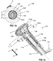
- Fig 1a shows a cross-sectional view of an assembly 100 for a hand brake valve in accordance with an embodiment of the present invention.
- Assembly 100 in addition to further components generally defines the hand brake valve, which may be utilized to actuate, for instance, the parking brakes of the vehicles. Said 'further components' are however believed not necessary for the understanding the subject-matter of the present invention.
- assembly 100 illustrated in Figs. 1a to 1f and assembly 200 shown in Figs. 2a and 2b are both different variations and are part of the hand brake valve.
- assembly 100 and 200 are not only configured to move within a slot or track 116 (see Figs.
- linear actuating options are configured such that one or more components of assembly 100 or 200 are configured to linearly reciprocate in relation to rod 102 or 202 to e.g., engage or disengage the parking brakes.
- Assembly 100 comprises a metal rod 102 with a non-circular external surface 102a, a handle insert 104 at least partially surrounding non-circular external surface 102a of metal rod 102.
- handle insert 104 is snugly fit such that it partially or completely surrounds surface 102a of metal rod 102 (more clearly represented in cut-sectional view of Fig 1b ). This is provided to "enable” the transfer of work from an operator of the hand brake valve to metal rod 116 without any twisting or turning between handle insert 104 and metal rod 102.
- handle insert 104 may be made of plastic based material. Due to the repeated usage and after a number of operating cycles of the hand brake valve, the plastic material of handle insert 104 wears out due to being in contact with "metal" rod 102 or due to the repeated impact force felt by handle insert 104 from "metal" rod 102. It is one of the objectives of the present invention to prevent an erosion of this positive assembly between metal rod 102 and handle insert 104 despite the repeated usage of the hand brake valve.
- assembly 100 of the present invention is provided with, among other elements, a structural means 100a that is configured to prevent any rotational movement (see 'R' in Fig 1b to understand what is meant with the term 'rotational') between handle insert 104 and at least metal rod 102.
- a structural means 100a that is configured to prevent any rotational movement (see 'R' in Fig 1b to understand what is meant with the term 'rotational') between handle insert 104 and at least metal rod 102.
- a skilled person would also envisage that one of the technical advantages of preventing any relative rotational movement between insert 104 and rod 102 is that to guarantee the actuation force applied by the operator of the hand brake valve is transferred to further components in assembly 100.
- Uncertainties caused due to the relative rotation between insert 104 and rod 102 are prevented such that e.g., the operator of the hand brake valve may not be misled that the proper and/or complete actuation of the hand brake valve has occurred and/or the force applied by the operator to the hand brake valve is transferred in a targeted manner within e.g., assembly 100 of the hand brake valve.
- structural means 100a comprises a pin 108, and a socket 106 for receiving pin 108.
- the technical advantage of an arrangement for structural means 100a with pin 108 and socket is that it prevents any rotational movement between handle insert 104 and at least metal rod 102, but at the same time enables a rectilinear movement (see 'RL' in Fig 1a to understand what is meant by 'rectilinear'; such movement is parallel to axis 'Y' which also labeled in the same figure) of at least handle insert 104 in relation to at least metal rod 102.
- a technical advantage is clearly derivable from e.g., Figs 1a and 1b of the accompanying drawings.
- gap 'g' generally between metal rod 102 and an internal surface 104s of insert 104.
- Said gap 'g' in association with the presence of length 'L' of socket 106 (see fig 1a ) enables said rectilinear movement of handle insert 104 in relation to at least metal rod 102.
- pin 108 movies within socket 106 of metal rod 102, said rectilinear movement of at least handle insert 104 in relation to at least metal rod 102 is facilitated.
- pin 108 extends through metal rod 102 and handle insert 104 so that any possibility of rotational movement between metal rod 102 and at least handle insert 104 is prevented.
- socket 106 extends completely through metal rod 102 and handle insert 104, and to the extent socket 106 extends completely through metal rod 102 and handle insert 104, socket 106 is longitudinally arranged such that pin 108 is capable of vertically sliding in a direction parallel to a vertical axis 'Y' within socket 106.
- pin 108 is in physical contact with at least the metal rod 102 and handle insert 104 and said pin 108 has a length that is lesser than an external diameter at a cross-sectional portion (A-A) of handle insert 104.
- pin 108 with mentioned length is commensurate to the requirement of not only preventing the rotational movement (see reference sign 'R' in fig 1b to show what is meant by the term 'rotational') between at least handle insert 104 and metal rod 102, but also be able to freely vertically slide within socket 106 (which passes through metal rod 102 and insert 104) along axis 'Y' (see Fig 1a ) and to maintain its horizontal orientation as restricted by dimensions of socket 106.
- structural means 100a is further configured to allow a rectilinear movement of handle insert 104 in relation to at least metal rod 102.
- the technical advantage of providing, for instance, the rectilinear movement is to enable further actuation positions of the hand brake valve that can be achieved through said rectilinear movement.
- the rectilinear movement of handle insert 104 in 'up' and 'down' directions can represent actuation states of engaging or disengaging the parking brake.
- see reference 'U' in fig 1a that is to be meant refer the direction 'up' and 'D' is meant to refer to the direction 'down'.
- Both of the movements 'up' and 'down' are part of e.g., the rectilinear movement 'RL', which is a movement with a direction that is also parallel to axis 'Y'.
- This illustration of up and down is provided in Fig 1a (also Fig 2a ) in order to merely avoid rendering such terms indefinite.
- the rectilinear movement that handle insert 104 is capable of, in particular in relation to metal rod 102 is derivable in view of a gap 'g' as labeled in Fig 1a .
- Fig 1b shows a cut section of assembly 100 for the hand brake valve explained in conjunction with Fig 1a , in accordance with an embodiment of the present invention. Said cut section of assembly 100 is marked at plane A-A in Fig 1a .
- the cut section of assembly 100 is provided to explain the arrangement of e.g., pin 108 in socket 106 in relation to other components of assembly 100.
- socket 106 extends through metal rod 102, handle insert 104 and an external shell 110
- the length of pin 10 is relatively lesser than e.g., diameter of handle insert 104 at section A-A.
- the dimensions or the shape of socket 106, to the extent it is present in external shell 110 is different vis-à-vis the dimensions or the shape of socket 106 at metal rod 102 shown in Fig 1a .
- socket 106 to the extent it is provided in external shell 110, is only helpful during the process of assembling assembly 100.
- the shape or dimensions of socket 106, to the extent, it is present in external shell 110 could be matching the shape or the dimensions of pin 108 or for instance, roughly cylindrical in shape as shown in Fig 1b .
- Fig 1c shows metal rod 102 used in conjunction with assembly 100 for the hand brake valve in accordance with an embodiment of the present invention.
- Fig 1d is cross-sectional view of metal rod 102 shown in conjunction with Fig 1c in accordance with an embodiment of the present invention.
- the details of metal rod 102 explained in conjunction with Figs 1a and 1b are applicable herewith in reference to figs. 1c and 1d .
- Fig 1e illustrates external shell 110 of assembly 100 for the hand brake valve in accordance with an embodiment of the present invention.
- Fig 1f is a cross-sectional view of external shell 110 illustrated in Fig 1e in accordance with an embodiment of the present invention. It is noted herewith that the features of external shell 110 explained above in reference to other figures and/or embodiments is applicable here.
- external shell 110 is positively coupled to handle insert 104, wherein external shell 110 encloses handle insert 104 at least partially.
- Socket 106 extends through external shell 110, and to extent socket 106 extends through external shell 110, socket 106 is shaped to at least approximately match the shape of pin 108.
- socket 106 extending through external shell 110 is configured to facilitate introduction of pin 108 during an assembly process of hand brake assembly 100.
- external shell 110 is positively coupled to handle insert 104 such that there is no relative rotational movement (see 'R' in Fig 1b to understand what is meant by the term 'rotational') possible between external shell 110 and handle insert 104.
- external shell 110 and handle insert 104 are configured to undergo a predetermined or a limited rectilinear movement in relation to metal rod 102 in a direction parallel to a vertical axis 'Y'. This is, for instance, enabled by presence of accommodating slot 118 in handle insert 104 as shown in Fig 1f .
- the shape of accommodating slot 118 enables the positively assembled external shell 110 and 104 to be able to undergo the rectilinear movement above metal rod 102. More particularly, the shape of accommodating slot 118 in insert 104 is designed in such a manner that at least partially matches with the external shape of metal rod 102.
- Fig 2a shows a cross-sectional view of another assembly 200 for a hand brake valve in accordance with another embodiment of the present invention.
- Assembly 200 could be considered as an alternative embodiment of assembly 100 for the hand brake valve.
- the primary difference lies between the two embodiments in terms of structural means 100a and structural means 200a.
- assembly 200 The functioning of assembly 200 will be described below.
- both structural means 100a and 200a are however configured to prevent any rotational movement (see 'R' in Fig 2b ) between the handle insert (104 or 204) and at least the metal rod (102 or 202). Furthermore, both structural means 100a and 200a are further configured to allow a rectilinear movement of the handle insert (104; 204) in relation to at least the metal rod (102; 202). See 'RL' in Fig 2a to understand what is meant by 'rectilinear'; such movement is parallel to axis 'Y' which also labeled in the same figure.
- a bush 206 is provided in order to prevent a relative rotation (see 'R' in Fig 2b ) between metal rod 202 and a combination of handle insert 204 and external shell 210.
- means 200a includes bush 206.
- Bush 206 has an internal surface matching the dimensions of non-circular external surface 202a of the metal rod 202.
- bush 206 is made of metal based material, and wherein handle insert 204 is overmolded to bush 206.
- handle insert 204 is made of plastic based material.
- external shell 210 associated with the present embodiment is provided with an internal surface 204s that is different from that of external shell 110 as disclosed in Figs 1a, 1b , 1e, and 1f of the present application. Furthermore, external shell 210 does not include any socket 106.
- bush 206 of means 200a is snugly fit to metal rod 202 such that it not only prevents any relative rotation (see 'R' in Fig 2b ) between metal rod 202 and a combination of handle insert 204 and external shell 210, but also enables, for instance, allow a rectilinear movement of at least handle insert 204 (or a combination of handle insert 204 and external shell 210) in relation to at least metal rod 202.
- Fig 2b is a cut section (A-A) of assembly 200 for the hand brake valve explained in conjunction with Fig 2a in accordance with another embodiment of the present invention.
- the cut section of assembly 200 displayed in Fig 2b shows, for instance, how bush 206 is assembled to metal rod 202.
- handle insert 204 is overmolded to bush 206.
- a snug fit exists between bush 206 and metal rod 202.
- bush 206 is made of metal. Due to metal - to-metal contact between bush 206 and metal rod 202, the wear and tear caused as a result of established contact between two components may be negligible. This prolongs the life of components in assembly 200 for the hand brake valve.
- bush 206 due to matching or snugly fit internal surfaces between bush 206 and metal rod 202, the rectilinear movement (limited or otherwise) between bush 206 and at least handle insert 204 is not blocked.
- the technical advantage of using bush 206 is that it not only prevents any relative rotation (see 'R' in Fig 2b to understand what is meant with the term 'rotation') between metal rod 202 and a combination of handle insert 204 and external shell 210, but also enables, for instance, allow a rectilinear movement of at least handle insert 204 (or a combination of handle insert 204 and external shell 210) in relation to at least metal rod 202.
- metal rod 102 or 202 may be provide with a work transmitting element 112.
- Said element 112 surrounds a portion of non-circular external surface 102a or 202a of metal rod 102 or 202 at its bottom portion ('bottom' relative to surface 104s or 204s of shell 110 or 210 - see Figs 1a and 2a ).
- element 112 may be configured to transmit force or work generated during the rectilinear movement (RL) transferred by operator the hand brake valve or specifically assembly 100 or 200 through e.g., a combination of external shell 110 or 210 and insert 104 or 204.
- said element 112 is configured to transmit force or work during the mentioned rectilinear movement to further components (not shown) of the hand brake valve underneath slot 116.
- Slot 116 in Figs. 1a and 2a shows where metal rod 102 or 202 is disposed and optionally in one or more embodiments, said slot 116 provides space and room for movement of metal rod 102 or 202 in a direction perpendicular to axis 'Y'.
- assembly 100 or 200 for the hand brake valve includes a spring 114 surrounding rod 102 or 202 to facilitate the rectilinear movement and/or facilitate user feedback of the rectilinear movement initiated by the user of the hand brake valve.
Landscapes
- Engineering & Computer Science (AREA)
- Physics & Mathematics (AREA)
- General Physics & Mathematics (AREA)
- Automation & Control Theory (AREA)
- Transportation (AREA)
- Mechanical Engineering (AREA)
- Lift Valve (AREA)
Description
- The present invention relates to the field of hand brake valves used in vehicles for applying brakes, in particular parking brakes. The present invention particularly finds application in trucks, heavy trucks and work vehicles where said hand brake valves are provided at a driver's cabin for engaging the parking brakes. Specifically, the present invention concerns an assembly for the hand brake valve.
- Hand brake valves are known to include a metal rod, a handle connected to the metal rod and other components which may facilitate the change of position of the brake valve between e.g., 'engaged' to 'disengaged' position or vice versa. In particular, the handle is provided above the metal rod. See, for instance,
Figure 1 of a German patent publication "DE 3346018 A1 " where handle '14' is shown to be provided above rod '6'. - After prolonged use of such hand brake valves, and due to wear and tear, the handle of the brake valve may get displaced or undergo relative movements with respect to e.g., the metal rod. Needless to say, such relative movements between the metal rod and the handle may not be desirable. In other words, the torque or work required to displace the handle in relation to the metal rod needs to properly transferred by the operator to the further components beneath the metal rod to apply the brakes and at the same time the operator needs to feel the 'feedback' in a precise manner.
- While the movement of the handle in relation to the metal rod per se is undesired, but in certain conditions it may result in an unreliable operation of the hand brake valve and compromise on the safety of the application of the parking brakes. For instance, in faulty situations the handle the relative movements may result in possible loss of locking function of the hand brake valves (i.e., parking position not stable). In some other conditions, the driver may be unaware if the assembly between the handle and the metal rod is clearly rendered broken or there is no friction between them. Needless to mention, this is unsafe as the engagement of the hand brake valve and the consequent change in the position of the parking brake needs to be guaranteed and the operator needs to be sure about the operation. An assembly of a handle mounted to a rod of non-circular cross-section is disclosed in German Utility Pattern
DE 8105742 U . An assembly for a hand brake valve comprising a handle that is axially movable on a rod is disclosed in European Patent ApplicationEP 1 900 583 A2 . - In the existing arts, one of the modes of addressing the above mentioned problems is to increase the regions of overlap between the handle and the metal rod. However, such solutions have generally not been found substantially adequate.
- The present invention is directed to address, among others, the above mentioned problem and at the same time to provide an improved hand brake valve for use in the vehicles.
- In accordance with an embodiment, an assembly for a hand brake valve is provided. The assembly comprises a metal rod with a non-circular external surface, a handle insert at least partially surrounding the non-circular external surface the metal rod, and, the assembly comprises structural means that is configured to prevent any rotational movement between the handle insert and at least the metal rod. The technical advantage of having the structural means so configured to prevent the relative rotational movement is that to guarantee the actuation force applied by the operator of the hand brake valve is transferred to further components in assembly. Uncertainties caused due to the relative rotation between insert and rod are prevented such that e.g., the operator of the hand brake valve may not be misled that the proper and/or complete actuation of the hand brake valve has occurred and/or the force applied by the operator to the hand brake valve is transferred in a targeted manner within e.g., the assembly of the hand brake valve.
- For instance, as mentioned above, in certain scenarios the torque required to rotate the handle insert or generally handle could be around approximately of the order of 5Nm (or 5 newton meter). It should be noted that this value is not to be considered as a definitive value. It has been provided only for the sake of understanding of the underlying invention. Due to the usage of the structural means according to the present invention, the torque required to rotate the handle has been increased. As a consequence, this renders the assembly of the device rigid and increases its robustness and prevents e.g., relative rotational movement or any other movement between the metal rod and e.g., the handle insert.
- In accordance with the same as the above embodiment or another embodiment, relating to the assembly for the hand brake valve, the structural means is further configured to allow a rectilinear movement of the handle insert in relation to at least the metal rod. The technical advantage of providing, for instance, the rectilinear movement is to enable further actuation positions of the hand brake valve. For instance, movement of the handle insert linearly in 'up' and 'down' directions can actuate states of engaging the hand brake valve.
- In accordance with yet another embodiment, the structural means comprises a pin, and a socket for receiving the pin. In the above-mentioned embodiment, the socket extends completely through the metal rod and the handle insert. In particular, to the extent the socket extends completely through the metal rod and the handle insert, the socket is longitudinally arranged such that the pin is capable of vertically sliding in a direction parallel to a vertical axis 'Y' within the socket. A skilled person would recognized that the technical advantage of the present embodiment with the mechanism of using the pin and the socket is to ensure the prevention of any rotational movement between the handle insert and at least the metal rod and at the same time enabling the rectilinear movement of the handle insert in relation to at least the metal rod.
- Further, in an embodiment, the pin is in physical contact with at least the metal rod and the handle insert and wherein the pin has a length that is lesser than an external diameter at a cross-sectional portion (A-A) of the handle insert. The technical consequence is the pin with mentioned length is commensurate to the requirement of not only preventing the rotational movement between at least the handle insert and the metal rod, but also be able to freely vertically slide within the socket along axis 'Y' and to maintain its horizontal orientation as restricted by dimensions of the socket (note: the socket passes through the metal rod and the insert).
- Furthermore, the structural means, in one or more of the above-mentioned embodiments, comprises a bush that has an internal surface matching the dimensions of the non-circular external surface of the metal rod. This is an alternative, as would also be apparent from the description below, to the pin and socket arrangement as explained in one or more of the above embodiments. The technical advantage of the using the bush is such that it enables the rectilinear movement between the handle insert and at least the metal rod, but prevents any relative rotational movement between them.
- Still further, the bush is made of metal based material, and preferably the handle insert is overmolded to the bush. In other words, the bush is placed below as e.g., a substrate as the molten material that forms part of the handle insert is allowed to be formed above the bush. The process of overmolding is, for instance, known to the person skilled in the art. The technical advantages of the overmolding process are well known when the materials such as metal is assigned for the bush and plastic assigned for the handle insert.
- In accordance with the present invention, the assembly further comprises an external shell which is positively coupled to the handle insert, wherein the external shell encloses at least the partially the handle insert. The external shell has the technical purpose of providing right amount of the grip to the operator of the hand brake valve and also provided to function as a cover to the other components of the assembly.
- In an embodiment, the socket preferably extends through the external shell, and to the extent the socket extends through the external shell, the socket is shaped to at least approximately match the shape of the pin. The technical purpose is to enable the insertion of the pin during the assembly so that pin is positioned within the socket that passes completely through the metal rod and the handle insert.
- In yet another embodiment, the socket extends through the external shell such that it is configured to facilitate introduction of the pin during an assembly process of the assembly for a hand brake assembly.
- In accordance with the present invention, the external shell is positively coupled to the handle insert such that there is no relative rotational movement possible between the external shell and the handle insert. The technical advantage is to facilitate the operator of the hand brake valve can have proper feedback and grip when, e.g., the metal rod is activated for shifting the parking brake position from 'engaged' to 'disengaged'.
- In an exemplary embodiment of the present invention, in the assembly of one or more of the above listed embodiments, the external shell and the handle insert are configured to undergo a predetermined or a limited rectilinear movement in relation to the metal rod in a direction parallel to a vertical axis 'Y'. The technical effect of this feature is to realize the purpose of the utilizing the pin and socket arrangement or the bush arrangement in association with the other components of the assembly. For instance, the limited rectilinear movement mentioned in the current embodiment is to allow change in the position of e.g., the parking brake from the engaged to the disengaged and/or further operating conditions.
- It is also clear that the assembly for the hand brake valve in vehicles as listed above can be used, in particular in trucks, for applying parking brakes.
- Further, technical advantages of the structural features and/or components of the assembly of the hand brake valve are explained in conjunction with the detailed description.
-
-
Fig 1a shows a cross-sectional view of an assembly for a hand brake valve in accordance with an embodiment of the present invention; -
Fig 1b shows a cut section of an assembly for a hand brake valve explained in conjunction withFig 1a , in accordance with an embodiment of the present invention; -
Fig 1c shows a metal rod used in conjunction with an assembly for a hand brake valve in accordance with an embodiment of the present invention; -
Fig 1d is cross-sectional view of a metal rod shown in conjunction withFig 1c in accordance with an embodiment of the present invention; -
Fig 1e illustrates an external shell of an assembly for a hand brake valve in accordance with an embodiment of the present invention; -
Fig 1f is a cross-sectional view of an external shell illustrated inFig 1e in accordance with an embodiment of the present invention; -
Fig 2a shows a cross-sectional view of another assembly for a hand brake valve in accordance with another embodiment of the present invention; and -
Fig 2b is a cut section of another assembly for a hand brake valve explained in conjunction withFig 2a in accordance with another embodiment of the present invention. -
Fig 1a shows a cross-sectional view of anassembly 100 for a hand brake valve in accordance with an embodiment of the present invention. - It is noted that a complete set of components that constitute the hand brake valve is not is not illustrated in the accompanying figures.
Assembly 100 in addition to further components generally defines the hand brake valve, which may be utilized to actuate, for instance, the parking brakes of the vehicles. Said 'further components' are however believed not necessary for the understanding the subject-matter of the present invention. In any case, it is noted thatassembly 100 illustrated inFigs. 1a to 1f andassembly 200 shown inFigs. 2a and 2b are both different variations and are part of the hand brake valve. In particular, in accordance with an exemplary illustration,assembly Figs. 1a and2a ) to performing the functions of the hand brake valve, but also include 'linear' actuating options. Said linear actuating options are configured such that one or more components ofassembly rod - Referring back to
Fig 1a , said figure discloses anassembly 100 for a hand brake valve.Assembly 100 comprises ametal rod 102 with a non-circularexternal surface 102a, ahandle insert 104 at least partially surrounding non-circularexternal surface 102a ofmetal rod 102. For instance, inFig 1a , it may be apparent that handleinsert 104 is snugly fit such that it partially or completely surroundssurface 102a of metal rod 102 (more clearly represented in cut-sectional view ofFig 1b ). This is provided to "enable" the transfer of work from an operator of the hand brake valve tometal rod 116 without any twisting or turning betweenhandle insert 104 andmetal rod 102. A skilled person may however realize that such an assembly betweenhandle insert 104 andmetal rod 102 may wear out over the duration of usage of the hand brake valve. For illustration, it could be considered that handleinsert 104 may be made of plastic based material. Due to the repeated usage and after a number of operating cycles of the hand brake valve, the plastic material ofhandle insert 104 wears out due to being in contact with "metal"rod 102 or due to the repeated impact force felt byhandle insert 104 from "metal"rod 102. It is one of the objectives of the present invention to prevent an erosion of this positive assembly betweenmetal rod 102 and handleinsert 104 despite the repeated usage of the hand brake valve. - Consequently,
assembly 100 of the present invention is provided with, among other elements, astructural means 100a that is configured to prevent any rotational movement (see 'R' inFig 1b to understand what is meant with the term 'rotational') betweenhandle insert 104 and atleast metal rod 102. A skilled person would also envisage that one of the technical advantages of preventing any relative rotational movement betweeninsert 104 androd 102 is that to guarantee the actuation force applied by the operator of the hand brake valve is transferred to further components inassembly 100. Uncertainties caused due to the relative rotation betweeninsert 104 androd 102 are prevented such that e.g., the operator of the hand brake valve may not be misled that the proper and/or complete actuation of the hand brake valve has occurred and/or the force applied by the operator to the hand brake valve is transferred in a targeted manner within e.g.,assembly 100 of the hand brake valve. - In accordance with the present embodiment,
structural means 100a comprises apin 108, and asocket 106 for receivingpin 108. The technical advantage of an arrangement forstructural means 100a withpin 108 and socket is that it prevents any rotational movement betweenhandle insert 104 and atleast metal rod 102, but at the same time enables a rectilinear movement (see 'RL' inFig 1a to understand what is meant by 'rectilinear'; such movement is parallel to axis 'Y' which also labeled in the same figure) of at least handleinsert 104 in relation to atleast metal rod 102. Such a technical advantage is clearly derivable from e.g.,Figs 1a and 1b of the accompanying drawings. - As shown in e.g.,
Fig 1a , there exists gap 'g' generally betweenmetal rod 102 and aninternal surface 104s ofinsert 104. Said gap 'g' in association with the presence of length 'L' of socket 106 (seefig 1a ) enables said rectilinear movement ofhandle insert 104 in relation to atleast metal rod 102. Aspin 108 movies withinsocket 106 ofmetal rod 102, said rectilinear movement of at least handleinsert 104 in relation to atleast metal rod 102 is facilitated. On the other hand, as shown in cut-sectional view ofFig 1b particularly,pin 108 extends throughmetal rod 102 and handleinsert 104 so that any possibility of rotational movement betweenmetal rod 102 and atleast handle insert 104 is prevented. - In accordance with the present embodiment or another, in order to clearly define the enablement of the rectilinear movement, it is noted that
socket 106 extends completely throughmetal rod 102 and handleinsert 104, and to theextent socket 106 extends completely throughmetal rod 102 and handleinsert 104,socket 106 is longitudinally arranged such thatpin 108 is capable of vertically sliding in a direction parallel to a vertical axis 'Y' withinsocket 106. - Further, in accordance with a preferred embodiment, and as shown in
Fig 1b ,pin 108 is in physical contact with at least themetal rod 102 and handleinsert 104 and saidpin 108 has a length that is lesser than an external diameter at a cross-sectional portion (A-A) ofhandle insert 104. The technical consequence is thatpin 108 with mentioned length is commensurate to the requirement of not only preventing the rotational movement (see reference sign 'R' infig 1b to show what is meant by the term 'rotational') between at least handleinsert 104 andmetal rod 102, but also be able to freely vertically slide within socket 106 (which passes throughmetal rod 102 and insert 104) along axis 'Y' (seeFig 1a ) and to maintain its horizontal orientation as restricted by dimensions ofsocket 106. - In accordance with the same as the above embodiment or another embodiment,
structural means 100a is further configured to allow a rectilinear movement ofhandle insert 104 in relation to atleast metal rod 102. The technical advantage of providing, for instance, the rectilinear movement is to enable further actuation positions of the hand brake valve that can be achieved through said rectilinear movement. For instance, the rectilinear movement ofhandle insert 104 in 'up' and 'down' directions can represent actuation states of engaging or disengaging the parking brake. In order to be further definite, see reference 'U' infig 1a that is to be meant refer the direction 'up' and 'D' is meant to refer to the direction 'down'. Both of the movements 'up' and 'down' are part of e.g., the rectilinear movement 'RL', which is a movement with a direction that is also parallel to axis 'Y'. This illustration of up and down is provided inFig 1a (alsoFig 2a ) in order to merely avoid rendering such terms indefinite. For another instance, the rectilinear movement that handleinsert 104 is capable of, in particular in relation tometal rod 102 is derivable in view of a gap 'g' as labeled inFig 1a . - As already explained above, the rectilinear movement in accordance with the embodiment associated with
assembly 100 is facilitated bystructural means 100a. -
Fig 1b shows a cut section ofassembly 100 for the hand brake valve explained in conjunction withFig 1a , in accordance with an embodiment of the present invention. Said cut section ofassembly 100 is marked at plane A-A inFig 1a . - More importantly, the cut section of
assembly 100 is provided to explain the arrangement of e.g.,pin 108 insocket 106 in relation to other components ofassembly 100. In the illustration ofFig 1b of the present embodiment, what is also derivable is, althoughsocket 106 extends throughmetal rod 102, handleinsert 104 and anexternal shell 110, the length of pin 10 is relatively lesser than e.g., diameter ofhandle insert 104 at section A-A. In an exemplary embodiment, the dimensions or the shape ofsocket 106, to the extent it is present inexternal shell 110, is different vis-à-vis the dimensions or the shape ofsocket 106 atmetal rod 102 shown inFig 1a . This is because, the provision ofsocket 106, to the extent it is provided inexternal shell 110, is only helpful during the process of assemblingassembly 100. For instance, the shape or dimensions ofsocket 106, to the extent, it is present inexternal shell 110 could be matching the shape or the dimensions ofpin 108 or for instance, roughly cylindrical in shape as shown inFig 1b . -
Fig 1c showsmetal rod 102 used in conjunction withassembly 100 for the hand brake valve in accordance with an embodiment of the present invention.Fig 1d is cross-sectional view ofmetal rod 102 shown in conjunction withFig 1c in accordance with an embodiment of the present invention. The details ofmetal rod 102 explained in conjunction withFigs 1a and 1b are applicable herewith in reference tofigs. 1c and 1d . -
Fig 1e illustratesexternal shell 110 ofassembly 100 for the hand brake valve in accordance with an embodiment of the present invention.Fig 1f is a cross-sectional view ofexternal shell 110 illustrated inFig 1e in accordance with an embodiment of the present invention. It is noted herewith that the features ofexternal shell 110 explained above in reference to other figures and/or embodiments is applicable here. - In accordance with one or more embodiments of the present invention,
external shell 110 is positively coupled to handleinsert 104, whereinexternal shell 110 encloseshandle insert 104 at least partially.Socket 106, for instance, extends throughexternal shell 110, and toextent socket 106 extends throughexternal shell 110,socket 106 is shaped to at least approximately match the shape ofpin 108. In accordance with the present embodiment,socket 106 extending throughexternal shell 110 is configured to facilitate introduction ofpin 108 during an assembly process ofhand brake assembly 100. - Further,
external shell 110 is positively coupled to handleinsert 104 such that there is no relative rotational movement (see 'R' inFig 1b to understand what is meant by the term 'rotational') possible betweenexternal shell 110 and handleinsert 104. - In the same embodiment,
external shell 110 and handleinsert 104 are configured to undergo a predetermined or a limited rectilinear movement in relation tometal rod 102 in a direction parallel to a vertical axis 'Y'. This is, for instance, enabled by presence ofaccommodating slot 118 inhandle insert 104 as shown inFig 1f . The shape ofaccommodating slot 118 enables the positively assembledexternal shell metal rod 102. More particularly, the shape ofaccommodating slot 118 ininsert 104 is designed in such a manner that at least partially matches with the external shape ofmetal rod 102. -
Fig 2a shows a cross-sectional view of anotherassembly 200 for a hand brake valve in accordance with another embodiment of the present invention.Assembly 200 could be considered as an alternative embodiment ofassembly 100 for the hand brake valve. The primary difference lies between the two embodiments in terms ofstructural means 100a andstructural means 200a. - The functioning of
assembly 200 will be described below. - As already mentioned, while there are differences between
structural means Fig 2b ) between the handle insert (104 or 204) and at least the metal rod (102 or 202). Furthermore, bothstructural means Fig 2a to understand what is meant by 'rectilinear'; such movement is parallel to axis 'Y' which also labeled in the same figure. - Since
structural means 100a has been explained in detail already above, focus is shifted tomeans 200a as shown inFig 2a in which the implementation is different vis-à-visstructural means 100a. In the present embodiment, in order to prevent a relative rotation (see 'R' inFig 2b ) betweenmetal rod 202 and a combination ofhandle insert 204 andexternal shell 210, abush 206 is provided. In other words, means 200a includesbush 206.Bush 206 has an internal surface matching the dimensions of non-circularexternal surface 202a of themetal rod 202. In one embodiment,bush 206 is made of metal based material, and whereinhandle insert 204 is overmolded tobush 206. In the same or different embodiment, handleinsert 204 is made of plastic based material. - Furthermore,
external shell 210 associated with the present embodiment is provided with aninternal surface 204s that is different from that ofexternal shell 110 as disclosed inFigs 1a, 1b ,1e, and 1f of the present application. Furthermore,external shell 210 does not include anysocket 106. - In accordance with the present embodiment,
bush 206 ofmeans 200a is snugly fit tometal rod 202 such that it not only prevents any relative rotation (see 'R' inFig 2b ) betweenmetal rod 202 and a combination ofhandle insert 204 andexternal shell 210, but also enables, for instance, allow a rectilinear movement of at least handle insert 204 (or a combination ofhandle insert 204 and external shell 210) in relation to atleast metal rod 202. -
Fig 2b is a cut section (A-A) ofassembly 200 for the hand brake valve explained in conjunction withFig 2a in accordance with another embodiment of the present invention. - The cut section of
assembly 200 displayed inFig 2b shows, for instance, howbush 206 is assembled tometal rod 202. As already mentioned in reference toFig 2a , handleinsert 204 is overmolded tobush 206. Further, a snug fit exists betweenbush 206 andmetal rod 202. In the present embodiment,bush 206 is made of metal. Due to metal - to-metal contact betweenbush 206 andmetal rod 202, the wear and tear caused as a result of established contact between two components may be negligible. This prolongs the life of components inassembly 200 for the hand brake valve. A skilled person would also recognize that due to matching or snugly fit internal surfaces betweenbush 206 andmetal rod 202, the rectilinear movement (limited or otherwise) betweenbush 206 and atleast handle insert 204 is not blocked. Thus, as mentioned above, the technical advantage of usingbush 206 is that it not only prevents any relative rotation (see 'R' inFig 2b to understand what is meant with the term 'rotation') betweenmetal rod 202 and a combination ofhandle insert 204 andexternal shell 210, but also enables, for instance, allow a rectilinear movement of at least handle insert 204 (or a combination ofhandle insert 204 and external shell 210) in relation to atleast metal rod 202. - Finally, it is also noted that, optionally,
metal rod work transmitting element 112. Saidelement 112 surrounds a portion of non-circularexternal surface metal rod shell 110 or 210 - seeFigs 1a and2a ). For instance,element 112 may be configured to transmit force or work generated during the rectilinear movement (RL) transferred by operator the hand brake valve or specifically assembly 100 or 200 through e.g., a combination ofexternal shell element 112 is configured to transmit force or work during the mentioned rectilinear movement to further components (not shown) of the hand brake valve underneathslot 116.Slot 116 inFigs. 1a and2a shows wheremetal rod slot 116 provides space and room for movement ofmetal rod assembly spring 114 surroundingrod -
- 100, 200 - an assembly for a hand brake valve
- 100a, 200a -structural means
- 102, 202 - metal rod
- 102a, 202a - non-circular external surface of
metal rod - 104, 204 - handle insert
- 104s, 204s - internal surface of
handle insert - 106 - socket
- 108 - pin
- 110, 210 - external shell
- 112 - a work transmitting element
- 114- spring
- 116 -slot or track
- 118 - accommodating slot for
metal rod - 206 -bush, preferably made of metal
- A-A - a reference cut-section plane of assembly 100 - the view of
assembly 100 at said cut-section plane is shown inFig 1a - RL - direction or orientation of the rectilinear movement
- R - orientation of rotational movement between e.g.,
metal rod 102a and handleinsert 104 - U - direction or orientation of the term 'upward' or 'up'
- D - direction or orientation of the term 'downward' or 'down' g - gap
- I - length of
pin 108 - d - diameter of
handle insert 104 at cut-section plane A-A - Y - longitudinal axis
Claims (10)
- An assembly (100; 200) for a hand brake valve, comprisinga metal rod (102; 202) with a non-circular external surface (102a; 202a);a handle insert (104; 204) at least partially surrounding the non-circular external surface (102a; 202a) of the metal rod (102; 202), and,wherein the assembly (100; 200) further comprises structural means (100a; 200a) that is configured to prevent any rotational movement between the handle insert (104; 204) and at least the metal rod (102; 202), characterized in that, the structural means (100a; 200a) is further configured to allow a rectilinear movement of the handle insert (104; 204) in relation to at least the metal rod (102; 202), in that the assembly (100; 200) further comprises an external shell (110; 210) which is positively coupled to the handle insert (104; 204), wherein the external shell (110; 210) encloses at least partially the handle insert (104 204), and in that the external shell (110; 210) is positively coupled to the handle insert (104; 204) such that there is no relative rotational movement possible between the external shell (110; 210) and the handle insert (104; 204).
- The assembly (100) of claim 1, wherein the structural means (100a) comprises a pin (108), and
a socket (106) for receiving the pin (108). - The assembly (100) of claim 2, wherein the socket (106) extends completely through the metal rod (102) and the handle insert (104), and to the extent the socket (106) extends completely through the metal rod (102) and the handle insert (104), the socket (106) is longitudinally arranged such that the pin (108) is capable of vertically sliding in a direction parallel to a vertical axis 'Y' within the socket (106).
- The assembly (100) of any one of claims 2 and 3, wherein the pin (108) is in physical contact with at least the metal rod (102) and the handle insert (104) and wherein the pin (108) has a length that is lesser than an external diameter at a cross-sectional portion (A-A) of the handle insert (104).
- The assembly (200) of claim 1, wherein the structural means (200a) comprises a bush (206) that has an internal surface matching the dimensions of the non-circular external surface (202a) of the metal rod (202).
- The assembly (200) of claim 5, wherein the bush (206) is made of metal based material, and wherein the handle insert (204) is overmolded to the bush (206).
- The assembly (100) of claim 1 and any one of claims 2 to 4, wherein the socket (106) extends through the external shell (110), and to the extent the socket (106) extends through the external shell (110), the socket (106) is shaped to at least approximately match the shape of the pin (108).
- The assembly (100) of claim 1, wherein the socket (106) extending through the external shell (110) is configured to facilitate introduction of the pin (108) during an assembly process of the hand brake assembly (100).
- The assembly (100; 200) of claim 1, wherein the external shell (110; 210) and the handle insert (104; 204) are configured to undergo a predetermined or a limited rectilinear movement in relation to the metal rod (102; 202) in a direction parallel to a vertical axis 'Y'.
- Use of the assembly (100; 200) for the hand brake valve in accordance with any one of the above claims in vehicles, in particular trucks, for applying parking brakes.
Priority Applications (1)
| Application Number | Priority Date | Filing Date | Title |
|---|---|---|---|
| EP19198872.4A EP3795439B1 (en) | 2019-09-23 | 2019-09-23 | Hand brake assembly with an anti-rotational lock |
Applications Claiming Priority (1)
| Application Number | Priority Date | Filing Date | Title |
|---|---|---|---|
| EP19198872.4A EP3795439B1 (en) | 2019-09-23 | 2019-09-23 | Hand brake assembly with an anti-rotational lock |
Publications (2)
| Publication Number | Publication Date |
|---|---|
| EP3795439A1 EP3795439A1 (en) | 2021-03-24 |
| EP3795439B1 true EP3795439B1 (en) | 2022-06-08 |
Family
ID=68062825
Family Applications (1)
| Application Number | Title | Priority Date | Filing Date |
|---|---|---|---|
| EP19198872.4A Active EP3795439B1 (en) | 2019-09-23 | 2019-09-23 | Hand brake assembly with an anti-rotational lock |
Country Status (1)
| Country | Link |
|---|---|
| EP (1) | EP3795439B1 (en) |
Family Cites Families (4)
| Publication number | Priority date | Publication date | Assignee | Title |
|---|---|---|---|---|
| US4356739A (en) * | 1980-04-01 | 1982-11-02 | Clark Equipment Company | Control rod handle |
| DE3346018A1 (en) | 1983-12-20 | 1985-06-27 | Knorr-Bremse GmbH, 8000 München | Handbrake or parking brake device for vehicles |
| DE19831195C2 (en) * | 1998-07-11 | 2000-05-04 | Audi Ag | Selector lever arrangement |
| DE102006043165B4 (en) * | 2006-09-14 | 2020-11-26 | Knorr-Bremse Systeme für Nutzfahrzeuge GmbH | Lever device for a hand brake valve of a brake system |
-
2019
- 2019-09-23 EP EP19198872.4A patent/EP3795439B1/en active Active
Also Published As
| Publication number | Publication date |
|---|---|
| EP3795439A1 (en) | 2021-03-24 |
Similar Documents
| Publication | Publication Date | Title |
|---|---|---|
| EP1021277B1 (en) | Ratchet wrench | |
| AU747009B2 (en) | Closing device for closing functions in vehicles in particular | |
| JP5431250B2 (en) | Key interlock device | |
| US6872905B2 (en) | Pushbutton for latching and momentary contact functions | |
| JP6210334B2 (en) | Selectable one-way clutch | |
| JPWO2019180824A1 (en) | Stabilizer device | |
| US9873163B2 (en) | Welding wire conveyor device | |
| EP3795439B1 (en) | Hand brake assembly with an anti-rotational lock | |
| US9534426B2 (en) | Child protector mechanism | |
| CN103459900B (en) | Device for preventing erroneous operation of manual transmission | |
| US9791885B2 (en) | Rotating-lever-position-holding device | |
| JP6448312B2 (en) | Shift lever unit | |
| JP6275176B2 (en) | Parking release unit | |
| KR102280350B1 (en) | limit switch | |
| EP1365429B1 (en) | Enable switch | |
| JP2016145498A (en) | Locking device for vehicle opening / closing body | |
| EP3452239B1 (en) | Pneumatic riveter comprising a lever and an unlocking assembly for inhibiting or enabling operation of the lever | |
| CN203787327U (en) | Option switch | |
| KR100661940B1 (en) | Rotation range regulating structure for manual plate of automatic transmission | |
| JPWO2015151882A1 (en) | Switch device | |
| US10533349B2 (en) | Door lock device for vehicle | |
| JP5152892B2 (en) | Switch device for vehicle | |
| JP2016088186A (en) | Shift lever unit | |
| KR20100007298U (en) | Device for improving the operating feeling of the manual transmission | |
| CN121447557A (en) | Ratchet control for a tool |
Legal Events
| Date | Code | Title | Description |
|---|---|---|---|
| PUAI | Public reference made under article 153(3) epc to a published international application that has entered the european phase |
Free format text: ORIGINAL CODE: 0009012 |
|
| STAA | Information on the status of an ep patent application or granted ep patent |
Free format text: STATUS: THE APPLICATION HAS BEEN PUBLISHED |
|
| AK | Designated contracting states |
Kind code of ref document: A1 Designated state(s): AL AT BE BG CH CY CZ DE DK EE ES FI FR GB GR HR HU IE IS IT LI LT LU LV MC MK MT NL NO PL PT RO RS SE SI SK SM TR |
|
| AX | Request for extension of the european patent |
Extension state: BA ME |
|
| RAP3 | Party data changed (applicant data changed or rights of an application transferred) |
Owner name: ZF CV SYSTEMS EUROPE BV |
|
| STAA | Information on the status of an ep patent application or granted ep patent |
Free format text: STATUS: REQUEST FOR EXAMINATION WAS MADE |
|
| 17P | Request for examination filed |
Effective date: 20210924 |
|
| RBV | Designated contracting states (corrected) |
Designated state(s): AL AT BE BG CH CY CZ DE DK EE ES FI FR GB GR HR HU IE IS IT LI LT LU LV MC MK MT NL NO PL PT RO RS SE SI SK SM TR |
|
| GRAP | Despatch of communication of intention to grant a patent |
Free format text: ORIGINAL CODE: EPIDOSNIGR1 |
|
| STAA | Information on the status of an ep patent application or granted ep patent |
Free format text: STATUS: GRANT OF PATENT IS INTENDED |
|
| INTG | Intention to grant announced |
Effective date: 20220316 |
|
| GRAS | Grant fee paid |
Free format text: ORIGINAL CODE: EPIDOSNIGR3 |
|
| GRAA | (expected) grant |
Free format text: ORIGINAL CODE: 0009210 |
|
| STAA | Information on the status of an ep patent application or granted ep patent |
Free format text: STATUS: THE PATENT HAS BEEN GRANTED |
|
| AK | Designated contracting states |
Kind code of ref document: B1 Designated state(s): AL AT BE BG CH CY CZ DE DK EE ES FI FR GB GR HR HU IE IS IT LI LT LU LV MC MK MT NL NO PL PT RO RS SE SI SK SM TR |
|
| REG | Reference to a national code |
Ref country code: AT Ref legal event code: REF Ref document number: 1496735 Country of ref document: AT Kind code of ref document: T Effective date: 20220615 Ref country code: CH Ref legal event code: EP |
|
| REG | Reference to a national code |
Ref country code: DE Ref legal event code: R096 Ref document number: 602019015615 Country of ref document: DE |
|
| REG | Reference to a national code |
Ref country code: IE Ref legal event code: FG4D |
|
| REG | Reference to a national code |
Ref country code: LT Ref legal event code: MG9D |
|
| REG | Reference to a national code |
Ref country code: NL Ref legal event code: MP Effective date: 20220608 |
|
| PG25 | Lapsed in a contracting state [announced via postgrant information from national office to epo] |
Ref country code: SE Free format text: LAPSE BECAUSE OF FAILURE TO SUBMIT A TRANSLATION OF THE DESCRIPTION OR TO PAY THE FEE WITHIN THE PRESCRIBED TIME-LIMIT Effective date: 20220608 Ref country code: NO Free format text: LAPSE BECAUSE OF FAILURE TO SUBMIT A TRANSLATION OF THE DESCRIPTION OR TO PAY THE FEE WITHIN THE PRESCRIBED TIME-LIMIT Effective date: 20220908 Ref country code: LT Free format text: LAPSE BECAUSE OF FAILURE TO SUBMIT A TRANSLATION OF THE DESCRIPTION OR TO PAY THE FEE WITHIN THE PRESCRIBED TIME-LIMIT Effective date: 20220608 Ref country code: HR Free format text: LAPSE BECAUSE OF FAILURE TO SUBMIT A TRANSLATION OF THE DESCRIPTION OR TO PAY THE FEE WITHIN THE PRESCRIBED TIME-LIMIT Effective date: 20220608 Ref country code: GR Free format text: LAPSE BECAUSE OF FAILURE TO SUBMIT A TRANSLATION OF THE DESCRIPTION OR TO PAY THE FEE WITHIN THE PRESCRIBED TIME-LIMIT Effective date: 20220909 Ref country code: FI Free format text: LAPSE BECAUSE OF FAILURE TO SUBMIT A TRANSLATION OF THE DESCRIPTION OR TO PAY THE FEE WITHIN THE PRESCRIBED TIME-LIMIT Effective date: 20220608 Ref country code: BG Free format text: LAPSE BECAUSE OF FAILURE TO SUBMIT A TRANSLATION OF THE DESCRIPTION OR TO PAY THE FEE WITHIN THE PRESCRIBED TIME-LIMIT Effective date: 20220908 |
|
| REG | Reference to a national code |
Ref country code: AT Ref legal event code: MK05 Ref document number: 1496735 Country of ref document: AT Kind code of ref document: T Effective date: 20220608 |
|
| PG25 | Lapsed in a contracting state [announced via postgrant information from national office to epo] |
Ref country code: RS Free format text: LAPSE BECAUSE OF FAILURE TO SUBMIT A TRANSLATION OF THE DESCRIPTION OR TO PAY THE FEE WITHIN THE PRESCRIBED TIME-LIMIT Effective date: 20220608 Ref country code: LV Free format text: LAPSE BECAUSE OF FAILURE TO SUBMIT A TRANSLATION OF THE DESCRIPTION OR TO PAY THE FEE WITHIN THE PRESCRIBED TIME-LIMIT Effective date: 20220608 |
|
| PG25 | Lapsed in a contracting state [announced via postgrant information from national office to epo] |
Ref country code: NL Free format text: LAPSE BECAUSE OF FAILURE TO SUBMIT A TRANSLATION OF THE DESCRIPTION OR TO PAY THE FEE WITHIN THE PRESCRIBED TIME-LIMIT Effective date: 20220608 |
|
| PG25 | Lapsed in a contracting state [announced via postgrant information from national office to epo] |
Ref country code: SM Free format text: LAPSE BECAUSE OF FAILURE TO SUBMIT A TRANSLATION OF THE DESCRIPTION OR TO PAY THE FEE WITHIN THE PRESCRIBED TIME-LIMIT Effective date: 20220608 Ref country code: SK Free format text: LAPSE BECAUSE OF FAILURE TO SUBMIT A TRANSLATION OF THE DESCRIPTION OR TO PAY THE FEE WITHIN THE PRESCRIBED TIME-LIMIT Effective date: 20220608 Ref country code: RO Free format text: LAPSE BECAUSE OF FAILURE TO SUBMIT A TRANSLATION OF THE DESCRIPTION OR TO PAY THE FEE WITHIN THE PRESCRIBED TIME-LIMIT Effective date: 20220608 Ref country code: PT Free format text: LAPSE BECAUSE OF FAILURE TO SUBMIT A TRANSLATION OF THE DESCRIPTION OR TO PAY THE FEE WITHIN THE PRESCRIBED TIME-LIMIT Effective date: 20221010 Ref country code: ES Free format text: LAPSE BECAUSE OF FAILURE TO SUBMIT A TRANSLATION OF THE DESCRIPTION OR TO PAY THE FEE WITHIN THE PRESCRIBED TIME-LIMIT Effective date: 20220608 Ref country code: EE Free format text: LAPSE BECAUSE OF FAILURE TO SUBMIT A TRANSLATION OF THE DESCRIPTION OR TO PAY THE FEE WITHIN THE PRESCRIBED TIME-LIMIT Effective date: 20220608 Ref country code: CZ Free format text: LAPSE BECAUSE OF FAILURE TO SUBMIT A TRANSLATION OF THE DESCRIPTION OR TO PAY THE FEE WITHIN THE PRESCRIBED TIME-LIMIT Effective date: 20220608 Ref country code: AT Free format text: LAPSE BECAUSE OF FAILURE TO SUBMIT A TRANSLATION OF THE DESCRIPTION OR TO PAY THE FEE WITHIN THE PRESCRIBED TIME-LIMIT Effective date: 20220608 |
|
| PG25 | Lapsed in a contracting state [announced via postgrant information from national office to epo] |
Ref country code: PL Free format text: LAPSE BECAUSE OF FAILURE TO SUBMIT A TRANSLATION OF THE DESCRIPTION OR TO PAY THE FEE WITHIN THE PRESCRIBED TIME-LIMIT Effective date: 20220608 Ref country code: IS Free format text: LAPSE BECAUSE OF FAILURE TO SUBMIT A TRANSLATION OF THE DESCRIPTION OR TO PAY THE FEE WITHIN THE PRESCRIBED TIME-LIMIT Effective date: 20221008 |
|
| REG | Reference to a national code |
Ref country code: DE Ref legal event code: R097 Ref document number: 602019015615 Country of ref document: DE |
|
| PG25 | Lapsed in a contracting state [announced via postgrant information from national office to epo] |
Ref country code: AL Free format text: LAPSE BECAUSE OF FAILURE TO SUBMIT A TRANSLATION OF THE DESCRIPTION OR TO PAY THE FEE WITHIN THE PRESCRIBED TIME-LIMIT Effective date: 20220608 |
|
| PLBE | No opposition filed within time limit |
Free format text: ORIGINAL CODE: 0009261 |
|
| STAA | Information on the status of an ep patent application or granted ep patent |
Free format text: STATUS: NO OPPOSITION FILED WITHIN TIME LIMIT |
|
| PG25 | Lapsed in a contracting state [announced via postgrant information from national office to epo] |
Ref country code: MC Free format text: LAPSE BECAUSE OF FAILURE TO SUBMIT A TRANSLATION OF THE DESCRIPTION OR TO PAY THE FEE WITHIN THE PRESCRIBED TIME-LIMIT Effective date: 20220608 Ref country code: DK Free format text: LAPSE BECAUSE OF FAILURE TO SUBMIT A TRANSLATION OF THE DESCRIPTION OR TO PAY THE FEE WITHIN THE PRESCRIBED TIME-LIMIT Effective date: 20220608 |
|
| REG | Reference to a national code |
Ref country code: CH Ref legal event code: PL |
|
| 26N | No opposition filed |
Effective date: 20230310 |
|
| REG | Reference to a national code |
Ref country code: BE Ref legal event code: MM Effective date: 20220930 |
|
| PG25 | Lapsed in a contracting state [announced via postgrant information from national office to epo] |
Ref country code: SI Free format text: LAPSE BECAUSE OF FAILURE TO SUBMIT A TRANSLATION OF THE DESCRIPTION OR TO PAY THE FEE WITHIN THE PRESCRIBED TIME-LIMIT Effective date: 20220608 |
|
| PG25 | Lapsed in a contracting state [announced via postgrant information from national office to epo] |
Ref country code: LU Free format text: LAPSE BECAUSE OF NON-PAYMENT OF DUE FEES Effective date: 20220923 |
|
| P01 | Opt-out of the competence of the unified patent court (upc) registered |
Effective date: 20230528 |
|
| PG25 | Lapsed in a contracting state [announced via postgrant information from national office to epo] |
Ref country code: LI Free format text: LAPSE BECAUSE OF NON-PAYMENT OF DUE FEES Effective date: 20220930 Ref country code: IE Free format text: LAPSE BECAUSE OF NON-PAYMENT OF DUE FEES Effective date: 20220923 Ref country code: CH Free format text: LAPSE BECAUSE OF NON-PAYMENT OF DUE FEES Effective date: 20220930 |
|
| PG25 | Lapsed in a contracting state [announced via postgrant information from national office to epo] |
Ref country code: BE Free format text: LAPSE BECAUSE OF NON-PAYMENT OF DUE FEES Effective date: 20220930 |
|
| PG25 | Lapsed in a contracting state [announced via postgrant information from national office to epo] |
Ref country code: IT Free format text: LAPSE BECAUSE OF FAILURE TO SUBMIT A TRANSLATION OF THE DESCRIPTION OR TO PAY THE FEE WITHIN THE PRESCRIBED TIME-LIMIT Effective date: 20220608 |
|
| PG25 | Lapsed in a contracting state [announced via postgrant information from national office to epo] |
Ref country code: CY Free format text: LAPSE BECAUSE OF FAILURE TO SUBMIT A TRANSLATION OF THE DESCRIPTION OR TO PAY THE FEE WITHIN THE PRESCRIBED TIME-LIMIT Effective date: 20220608 |
|
| PG25 | Lapsed in a contracting state [announced via postgrant information from national office to epo] |
Ref country code: MK Free format text: LAPSE BECAUSE OF FAILURE TO SUBMIT A TRANSLATION OF THE DESCRIPTION OR TO PAY THE FEE WITHIN THE PRESCRIBED TIME-LIMIT Effective date: 20220608 Ref country code: HU Free format text: LAPSE BECAUSE OF FAILURE TO SUBMIT A TRANSLATION OF THE DESCRIPTION OR TO PAY THE FEE WITHIN THE PRESCRIBED TIME-LIMIT; INVALID AB INITIO Effective date: 20190923 |
|
| PG25 | Lapsed in a contracting state [announced via postgrant information from national office to epo] |
Ref country code: TR Free format text: LAPSE BECAUSE OF FAILURE TO SUBMIT A TRANSLATION OF THE DESCRIPTION OR TO PAY THE FEE WITHIN THE PRESCRIBED TIME-LIMIT Effective date: 20220608 |
|
| PG25 | Lapsed in a contracting state [announced via postgrant information from national office to epo] |
Ref country code: MT Free format text: LAPSE BECAUSE OF FAILURE TO SUBMIT A TRANSLATION OF THE DESCRIPTION OR TO PAY THE FEE WITHIN THE PRESCRIBED TIME-LIMIT Effective date: 20220608 |
|
| PG25 | Lapsed in a contracting state [announced via postgrant information from national office to epo] |
Ref country code: BG Free format text: LAPSE BECAUSE OF FAILURE TO SUBMIT A TRANSLATION OF THE DESCRIPTION OR TO PAY THE FEE WITHIN THE PRESCRIBED TIME-LIMIT Effective date: 20220608 |
|
| PG25 | Lapsed in a contracting state [announced via postgrant information from national office to epo] |
Ref country code: BG Free format text: LAPSE BECAUSE OF FAILURE TO SUBMIT A TRANSLATION OF THE DESCRIPTION OR TO PAY THE FEE WITHIN THE PRESCRIBED TIME-LIMIT Effective date: 20220608 |
|
| PGFP | Annual fee paid to national office [announced via postgrant information from national office to epo] |
Ref country code: DE Payment date: 20250702 Year of fee payment: 7 |
|
| PGFP | Annual fee paid to national office [announced via postgrant information from national office to epo] |
Ref country code: GB Payment date: 20250703 Year of fee payment: 7 |
|
| PGFP | Annual fee paid to national office [announced via postgrant information from national office to epo] |
Ref country code: FR Payment date: 20250808 Year of fee payment: 7 |