EP3795362A1 - Printhead assembly and inkjet printer - Google Patents
Printhead assembly and inkjet printer Download PDFInfo
- Publication number
- EP3795362A1 EP3795362A1 EP20199912.5A EP20199912A EP3795362A1 EP 3795362 A1 EP3795362 A1 EP 3795362A1 EP 20199912 A EP20199912 A EP 20199912A EP 3795362 A1 EP3795362 A1 EP 3795362A1
- Authority
- EP
- European Patent Office
- Prior art keywords
- ink
- tower
- slider
- printhead assembly
- trenches
- Prior art date
- Legal status (The legal status is an assumption and is not a legal conclusion. Google has not performed a legal analysis and makes no representation as to the accuracy of the status listed.)
- Granted
Links
Images




Classifications
-
- B—PERFORMING OPERATIONS; TRANSPORTING
- B41—PRINTING; LINING MACHINES; TYPEWRITERS; STAMPS
- B41J—TYPEWRITERS; SELECTIVE PRINTING MECHANISMS, i.e. MECHANISMS PRINTING OTHERWISE THAN FROM A FORME; CORRECTION OF TYPOGRAPHICAL ERRORS
- B41J2/00—Typewriters or selective printing mechanisms characterised by the printing or marking process for which they are designed
- B41J2/005—Typewriters or selective printing mechanisms characterised by the printing or marking process for which they are designed characterised by bringing liquid or particles selectively into contact with a printing material
- B41J2/01—Ink jet
- B41J2/17—Ink jet characterised by ink handling
- B41J2/175—Ink supply systems ; Circuit parts therefor
- B41J2/17503—Ink cartridges
- B41J2/17513—Inner structure
-
- B—PERFORMING OPERATIONS; TRANSPORTING
- B41—PRINTING; LINING MACHINES; TYPEWRITERS; STAMPS
- B41J—TYPEWRITERS; SELECTIVE PRINTING MECHANISMS, i.e. MECHANISMS PRINTING OTHERWISE THAN FROM A FORME; CORRECTION OF TYPOGRAPHICAL ERRORS
- B41J2/00—Typewriters or selective printing mechanisms characterised by the printing or marking process for which they are designed
- B41J2/005—Typewriters or selective printing mechanisms characterised by the printing or marking process for which they are designed characterised by bringing liquid or particles selectively into contact with a printing material
- B41J2/01—Ink jet
- B41J2/135—Nozzles
- B41J2/14—Structure thereof only for on-demand ink jet heads
- B41J2/14016—Structure of bubble jet print heads
- B41J2/14088—Structure of heating means
-
- B—PERFORMING OPERATIONS; TRANSPORTING
- B41—PRINTING; LINING MACHINES; TYPEWRITERS; STAMPS
- B41J—TYPEWRITERS; SELECTIVE PRINTING MECHANISMS, i.e. MECHANISMS PRINTING OTHERWISE THAN FROM A FORME; CORRECTION OF TYPOGRAPHICAL ERRORS
- B41J2/00—Typewriters or selective printing mechanisms characterised by the printing or marking process for which they are designed
- B41J2/005—Typewriters or selective printing mechanisms characterised by the printing or marking process for which they are designed characterised by bringing liquid or particles selectively into contact with a printing material
- B41J2/01—Ink jet
- B41J2/17—Ink jet characterised by ink handling
- B41J2/175—Ink supply systems ; Circuit parts therefor
- B41J2/17503—Ink cartridges
- B41J2/17526—Electrical contacts to the cartridge
- B41J2/1753—Details of contacts on the cartridge, e.g. protection of contacts
-
- B—PERFORMING OPERATIONS; TRANSPORTING
- B41—PRINTING; LINING MACHINES; TYPEWRITERS; STAMPS
- B41J—TYPEWRITERS; SELECTIVE PRINTING MECHANISMS, i.e. MECHANISMS PRINTING OTHERWISE THAN FROM A FORME; CORRECTION OF TYPOGRAPHICAL ERRORS
- B41J2/00—Typewriters or selective printing mechanisms characterised by the printing or marking process for which they are designed
- B41J2/005—Typewriters or selective printing mechanisms characterised by the printing or marking process for which they are designed characterised by bringing liquid or particles selectively into contact with a printing material
- B41J2/01—Ink jet
- B41J2/17—Ink jet characterised by ink handling
- B41J2/175—Ink supply systems ; Circuit parts therefor
- B41J2/17503—Ink cartridges
- B41J2/17553—Outer structure
-
- B—PERFORMING OPERATIONS; TRANSPORTING
- B41—PRINTING; LINING MACHINES; TYPEWRITERS; STAMPS
- B41J—TYPEWRITERS; SELECTIVE PRINTING MECHANISMS, i.e. MECHANISMS PRINTING OTHERWISE THAN FROM A FORME; CORRECTION OF TYPOGRAPHICAL ERRORS
- B41J2/00—Typewriters or selective printing mechanisms characterised by the printing or marking process for which they are designed
- B41J2/005—Typewriters or selective printing mechanisms characterised by the printing or marking process for which they are designed characterised by bringing liquid or particles selectively into contact with a printing material
- B41J2/01—Ink jet
- B41J2/17—Ink jet characterised by ink handling
- B41J2/175—Ink supply systems ; Circuit parts therefor
- B41J2/17563—Ink filters
Definitions
- the present invention relates generally to inkjet printers, and more particularly, to a printhead assembly for inkjet printers.
- An inkjet printer typically includes a printhead and a carrier.
- the inkjet printhead can comprise a printhead body, nozzles, and corresponding ink ejection actuators, such as heaters on a printhead chip.
- the actuators cause ink to be ejected from the nozzles onto a print medium at selected ink dot locations within an image area.
- the carrier moves the printhead relative to the medium, while the ink dots are jetted onto selected pixel locations, such as by heating the ink at the nozzles.
- the ink reservoir comprises a removable or separable tank, such that the tank can be separated from the printhead, and replaced or refilled, when the ink is low.
- the printhead components can then be re-used.
- a separable fluid connection between the tank and the printhead body is needed, in contrast to systems where the printhead body is integral with the ink reservoir. The connection permits ink to flow to the nozzles from the tank, but is separable such that the ink tank can be removed when empty.
- the printhead assembly may also include a filter within an ink passageway leading from the ink reservoir to the nozzles, for isolating any contaminants or debris from the ejectors and nozzles.
- a chamber located between the filter and the nozzle is referred to as the ink filter tower as it contains ink after it is filtered.
- the inks that are typically used for ink jet printing include dye inks and pigment inks.
- a significant problem associated with the use of pigment inks has been the settling of particles in the bottom of the main ink reservoir(s) of a printhead when a printhead sits idle for a while. This problem is especially pronounced with pigment inks that are designed to set quickly onto a printed surface. The settling of the ink can cause nozzles on the printhead to become clogged and malfunction and may produce lighter coloration on a printed document.
- a free-floating member for example, a weighted slider
- the ink filter tower has extending elements, for example, pillars, that extend laterally across the tower. Trenches are formed between these pillars.
- a slider includes a bridging member and a plurality of downward-pointed, substantially parallel shafts connected to the bridging member. In constructing the tower, the slider of this design is installed in a free-floating position with the bridging member situated above the extending elements and at least one of the shafts situated within a trench.
- the slider is weighted so that it remains approximately within the desired vertical position and is constrained by the location of the shaft(s) within the trench(es) to move in a substantially lateral direction within the ink filter tower.
- the ink within the ink filter tower serves as a lubricant for movement of the slider.
- the slider moves in a direction opposite to the direction of motion of the printhead assembly to agitate the filtered ink within the ink filter tower.
- the bridging member may comprise a bar with a flat upper surface and the shafts comprise columns of a rectangular cross-section. In another embodiment, the bridging member may comprise a curved upper surface and the shafts comprise columns of a rectangular cross-section. In yet another embodiment, the bridging member may be a rod that permits the slider to pivot and slide, and the slider shafts are rotatable along the axis formed by the rod.
- FIG. 1 shows an inkjet printhead generally designated by reference number 101.
- the printhead 101 has a housing 127 formed of a lid 161 and a body 163 assembled together through attachment or connection of a lid bottom surface and a body top surface at interface 171.
- the shape of the housing varies and depends upon the external device that carries or contains the printhead, the amount of ink to be contained in the printhead and whether the printhead contains one or more varieties of ink.
- the housing or body has at least one compartment in an interior thereof for holding an initial or refillable supply of ink and a structure, such as a foam insert, lung or other, for maintaining appropriate backpressure in the inkjet printhead during use.
- the compartment contains black ink, photo-ink and/or plurals of cyan, magenta or yellow ink. It will be appreciated that fluid connections (not shown) may exist to connect the compartment(s) to a remote source of bulk ink.
- a portion 205 of a tape automated bond (TAB) circuit 201 adheres to one surface 181 of the housing while another portion 211 adheres to another surface 221. As shown, the two surfaces 181, 221 exist perpendicularly to one another about an edge 231.
- the TAB circuit 201 has a plurality of input/output (I/O) connectors 241 fabricated thereon for electrically connecting a heater chip 251 to an external device, such as a printer, fax machine, copier, photo-printer, plotter, all-in-one, etc., during use.
- I/O input/output
- Pluralities of electrical conductors 261 exist on the TAB circuit 201 to electrically connect and short the I/O connectors 241 to the bond pads 281 of the heater chip 251 and various manufacturing techniques are known for facilitating such connections. It will be appreciated that while eight I/O connectors 241, eight electrical conductors 261 and eight bond pads 281 are shown, any number are embraced herein. It is also to be appreciated that such number of connectors, conductors and bond pads may not be equal to one another.
- the heater chip 251 contains at least one ink via 321 that fluidly connects to a supply of ink in an interior of the housing.
- the number of ink vias of the heater chip corresponds one-to-one with the number of ink types contained within the housing interior.
- the vias usually reside side-by-side or end-to-end.
- the heater chip 251 preferably attaches to the housing with any of a variety of adhesives, epoxies, etc. well known in the art.
- the heater chip contains four rows (rows A-row D) of fluid firing elements, especially resistive heating elements, or heaters. For simplicity, dots depict the heaters in the rows and typical printheads contain hundreds of heaters.
- the heaters of the heater chip preferably become formed as a series of thin film layers made via growth, deposition, masking, photolithography and/or etching or other processing steps.
- the heater chip is merely a semiconductor die that contains piezoelectric elements, as the fluid firing elements, for electro-mechanically ejecting ink.
- the term heater chip will encompass both embodiments despite the name "heater” implying an electro-thermal ejection of ink.
- the entirety of the heater chip may be configured as a side-shooter structure instead of the roof-shooter structure shown.
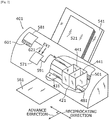
- FIG. 2 shows an external device in the form of an inkjet printer for containing the printhead 101, generally designated by reference number 401.
- the printer 401 includes a carriage 421 having a plurality of slots 441 for containing one or more printheads.
- the carriage 421 is caused to reciprocate (via an output 591 of a controller 571) along a shaft 481 above a print zone 431 by a motive force supplied to a drive belt 501 as is well known in the art.
- the reciprocation of the carriage 421 is performed relative to a print medium, such as a sheet of paper 521, that is advanced in the printer 401 along a paper path from an input tray 541, through the print zone 431, to an output tray 561.
- the carriage 421 reciprocates in the Reciprocating Direction generally perpendicularly to the paper Advance Direction as shown by the arrows.
- Ink drops from the printheads are caused to be ejected from the heater chip 251 ( FIG. 1 ) at such times pursuant to commands of a printer microprocessor or other controller 571.
- the timing of the ink drop emissions corresponds to a pattern of pixels of the image being printed. Oftentimes, such patterns are generated in devices electrically connected to the controller (via EXT input) that are external to the printer such as a computer, a scanner, a camera, a visual display unit, a personal data assistant, or other.
- a control panel 581 having user selection interface 601 may also provide input 621 to the controller 571 to enable additional printer capabilities and robustness.
- the fluid firing elements (the dots of rows A-D, FIG. 1 ) are uniquely addressed with a small amount of current to rapidly heat a small volume of ink. This causes the ink to vaporize in a local ink chamber and be ejected through the nozzle plate towards the print medium.
- the fire pulse required to emit such ink drop may embody a single or a split firing pulse and is received at the heater chip on an input terminal (e.g., bond pad 281) from connections between the bond pad 281, the electrical conductors 261, the I/O connectors 241 and controller 571.
- Internal heater chip wiring conveys the fire pulse from the input terminal to one or many of the fluid firing elements.
- FIG. 3 is an exploded perspective view and FIGS. 4 and 5 are cross-sectional views of a printhead assembly, generally designated as reference number 1, according to an exemplary embodiment of the present invention.
- the printhead assembly 1 includes an ink cartridge body 10, filter 20, filter cap 30, gasket 40, ink reservoir 50, fill ball 60 and lid 70.
- the ink cartridge body 10 has a chamber 12 that is sized and configured to receive the ink reservoir 50. Although only one ink reservoir 50 is shown in the figures, it should be appreciated that multiple ink reservoirs may be provided to accommodate one or more color inks.
- the ink reservoir 50 includes an exit port 52 for delivery of the ink, once installed in the chamber 12, and the port 52 can include an interface structure as appropriate, such as a lip or extension.
- the exit port 52 can be sealed using a removable seal, which can be removed at the time of installation.
- a print head chip (or "nozzle plate”) 11 including a plurality of nozzles for delivery of the ink to the print medium.
- the nozzles are provided on a structure separate from the chip.
- the ink flows from the exit port 52 of the ink reservoir 50 through channels in the lower portion of the body 10.
- the ink then flows within the body 10 to a manifold in the print head chip 11, from which it is drawn to the nozzles for ejection onto the print medium, such as by using heater elements or piezoelectric elements formed in the chip 11.
- the system 1 is moved relative to the print medium, such that the nozzles drop ink at one or more desired locations on the medium.
- the lower portion of the ink cartridge body 10 includes a tower 14 (or "ink filter tower”).
- the tower 14 may include any appropriate entrance passage, extension, structure, port, or interface for receiving ink for printing.
- the tower 14 of this example includes an ink raised tubular extension, or standpipe, having one or more openings 15 through which the ink may flow from the ink reservoir 50 to another reservoir formed by chamber 75 within tower 14.
- Multiple extending elements, for example, pillars 81, 82, 83, attached at the bottom of chamber 75, are spaced apart from, and substantially parallel to, one another. While only three pillars shown in FIG.
- the filter cap 30 engages the tower 14, and in particular may be welded to an upstanding outer perimeter wall of the tower 14.
- the filter cap 30 includes a conduit or guide component for providing a passage between the ink cartridge body 10 and the ink reservoir 50.
- the filter cap 30 includes an inner passage 32 for providing ink therethrough, the passage 32 being defined by a smaller diameter upper passage portion 34 at the ink reservoir end and a larger diameter lower passage portion 36 at the ink cartridge body end.
- the filter cap 30 may be made of a polyamide, such as, for example, nylon, or other suitable materials that can provide a fluid resistant seal against the tower 14, ink cartridge body 10, and/or ink reservoir 50.
- the upper passage portion 34 of the filter cap 30 engages a corresponding exit port 52 of the ink reservoir 50 to allow ink to flow from the ink reservoir 50 to the passage 32 of the filter cap 30.
- a sealing member is disposed adjacent the filter cap 30 and assists in sealing between the filter cap 30 and the ink reservoir 50.
- the sealing member includes the gasket 40 that engages the upper passage portion 34, so as to create a fluidic seal to control fluid and evaporative losses from the system, and prevent air from entering the system to maintain back pressure.
- the gasket 40 may be made of a suitable elastomer material, or other material with good sealing properties.
- the filter 20 filters contaminants in the ink from reaching the printhead chip.
- the filter 20 can also provide capillary functions to allow ink to pass upon demand to the printhead chip and to prevent air passage into the printhead chip.
- the filter 20 can be made of a metal weave, a polymer weave, or other mesh, screen, or weave materials. For instance, a stainless steel dutch twill or a stainless steel random weave material may be used to form the filter 20.
- the filter 20 may be insert injection molded in the tower 14, or otherwise disposed in the ink cartridge body 10. As another example, the filter 20 may be heat staked to the ink cartridge body 10.
- the material used to form the ink cartridge body 10 and associated lid 70 may be, for example, Nylon 6,6, Nylon 6, Nylon 6,12, polyethersulfone, polypropylene, polyethylene, and polyoxymethylene or other materials that are compatible with ketone, acetate and alcohol base inks. Since these materials exhibit vapor loss through permeation, a secondary boundary may be provided in the form of the ink reservoir 50.
- the ink reservoir 50 may be made of polypropylene and/or polyethylene based materials so as to create a sufficient permeation barrier.
- the ink reservoir 50 is also provided with foam or felt materials.
- the ink reservoir 50 provides the primary permeation boundary for the ink cartridge body 10 and when the ink reservoir 50 is attached internally to the ink cartridge body 10 and lid 70, a tortuous vent path is created having a high length to area ratio. This tortuous path allows air to move through it, while maintaining a high humidity environment, which reduces evaporative losses and greatly reduces permeation from the system.
- ink filter tower 14 also has a free-floating member such as a metallic, weighted slider 80 installed within ink filter tower 14 in order to prevent ink from from settling within tower 14.
- Slider 80 is free-floating in the sense that it is not physically connected to the other elements in tower 14.
- Slider 80 is installed in the ink filter tower before the welding of the ink filter 30 above ink filter tower 14. Thereafter, felt or foam is installed in ink filter reservoir 50 that is attached above ink filter 20. After the felt or foam is installed, ink is injected into the reservoir and passes into the ink filter tower.
- Slider 80 is generally comprised of a bridging member 88, such as a connecting bar or rod at its upper side, and multiple rectangular-shaped vertical shafts 84, 85, 86 formed integrally with the bridging member 88 that connects the shafts.
- Shafts 84, 85, and 86 which are typically sealed and may be solid or have a hollow core, protrude downward from the bridging member such that they are substantially parallel to one another.
- the slider shafts, while substantially parallel, need not be of equal width. It is, indeed, desirable that the slider shafts are dimensioned to be as large as possible both within and outside the trenches such that the ink is agitated as much as possible while the slider can still free-float.
- Slider 80 is positioned in ink filter tower 14 so that at least some of the shafts 84, 85 are situated within trenches 89, 90 while one or more shafts, such as shaft 86 may sit in chamber 75 adjacent passage 83 but outside of the trenches.
- the configuration and weight of the bridging member 88 and the shafts constrains slider 80 in a free-floating position relative to the pillars to enable substantially lateral movement from side to side of the printhead assembly without twisting or getting stuck.
- the ink in chamber 75 acts as a lubricant that enables the slider to move from side to side back and forth within the ink filter tower, but the viscosity of the ink also slows the movement of the slider so that it does not move too rapidly.
- the movement of slider 80 from side to side is initiated by the reciprocating motion of the printhead carrier during printing.
- the direction of motion of the slider 80 is opposite to the direction of motion of the printhead assembly.
- slider 80 moves to the left.
- slider 80 moves to the right.
- This helps to agitate the ink within the ink filter tower, including the ink near and around the nozzle plate area, to mitigate the settling of ink that would otherwise occur.
- the ink agitation also helps to mix the ink that may have already settled, such as after a period of non-use of the printer.
- a slider may move in a direction opposite to the reciprocating direction of the carrier at, for example, 14-15 inches / second.
- the speed of the slider may depend on factors such as the weight of the slider and the composition of the ink. However, the actual speed of slider movement is not limited to any particular value.
- An ink filter tower of this design is particularly useful for pigmented inks where ink settling is a problem.
- mono ink i.e., black ink
- the present invention would also be useful with pigmented ink of other colors.
- Slider 80 may be formed from a metallic material, such as stainless steel, and may be encapsulated or coated so as to prevent the metal from being in direct contact with the ink, should the ink used deleteriously interact with the metal.
- the slider 80 is weighted so as to promote movement of the slider within the ink filter tower.
- the weight of the slider is approximately in the range of 0.45 to 0.5 grams.
- FIG. 7 shows a perspective view of a first embodiment of slider 80 according to the present invention.
- slider 80' has a bridging member with a substantially flat upper surface 88' and downward-facing shafts 84', 85', and 86' separated by channels 87a, 87b. It can be seen that these shafts are columnar in shape with a rectangular cross-section. Shaft 86' may be wider than shafts 84' and 85'. This may be desirable where shaft 86' is positioned outside of a trench and there is space within chamber 75 to accommodate a shaft of a larger cross-section for maximum agitation of the ink.
- the perimeters of the bridging member 81' and the vertical edges of the shafts may be beveled to enhance the motion of the slider and prevent the slider from getting stuck.
- FIG. 8 shows a perspective view of a second embodiment of slider 80 according to the present invention.
- slider 80" has a bridging member with a curved upper surface 88" and shafts 84", 85" and 86" that are columnar in shape with a rectangular cross-section.
- shaft 86" may be wider than shafts 84" and 85" and the edges of the slider 80" may be beveled.
- FIG. 9 shows a perspective view of a third embodiment of slider 80 according to the present invention.
- slider 80''' is shaped as a cam shaft where bridging member 88''' is a rod and shafts 84''', 85''' and 86''' are shaped as circular sectors in cross-section.
- the side walls of 84''', 85''' and 86''' remain substantially parallel to one another.
- This design adds an additional degree of freedom to the motion of the free-floating slider so that the slider 88''' not only slides across the pillars 81, 82, 83 but can also pivot about the axis formed by rod 88''', to increase the agitation of the ink and prevent settling thereof.
- FIG. 10 shows a perspective view of the slider 80''' according to the third embodiment as viewed at line X-X of FIG. 9 .
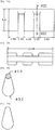
- FIGs. 11 to 13 shows examples of possible dimensions (in units of mm) for the three different embodiments of a slider 80, shown in FIGs. 7 to 9 .
- FIG. 11A is a side elevational view of the slider of FIG. 7 in accordance with the first embodiment of the present invention.
- FIG. 11B is a top view of the slider of FIG. 11A.
- FIG. 11C is a cross-sectional view of the slider along line XI-XI of FIG. 11B .
- FIG. 12A is a side elevational view of the slider of FIG. 8 in accordance with a second embodiment of the present invention.
- FIG. 12B is a top view of the slider of FIG. 12A.
- FIG. 12C is a cross-sectional view of the slider along line XII-XII of FIG. 12A.
- FIG. 12D is a side view of the slider of FIG. 12A .
- FIG. 13A is a side elevational view of the slider of FIG. 9 in accordance with a third embodiment of the present invention.
- FIG. 13B is a top view of the slider of FIG. 13A.
- FIG. 13C is a cross-sectional view of the slider along line XIII-XIII of FIG. 13A.
- FIG. 13D is a side view of the slider of FIG. 13A .
- the present invention thus serves to agitate the ink in the ink filter tower, and thereby reduces nozzle outages on the printhead assembly and enables a darker coloration of the printed samples.
Landscapes
- Ink Jet (AREA)
- Particle Formation And Scattering Control In Inkjet Printers (AREA)
Abstract
a) an ink cartridge body (10);
b) an ink reservoir (50) disposed within the ink cartridge body and adapted to receive and contain ink;
c) the ink cartridge body (10) including a tower (14);
d1) a chamber (75) inside the tower (14) that holds ink;
d2) a plurality of extending elements formed by pillars (81, 82, 83) attached at the bottom of the chamber (75) disposed within the chamber, the ink passing through the chamber and around the plurality of extending elements, wherein the extending elements are spaced apart from, and are substantially parallel to, one another;
d3) a plurality of trenches (89, 90) disposed within the chamber, wherein the plurality of trenches are defined by the spaces between the extending elements; and
d4) a free-floating member formed as a slider (80)
Description
- The present invention relates generally to inkjet printers, and more particularly, to a printhead assembly for inkjet printers.
- An inkjet printer typically includes a printhead and a carrier. The inkjet printhead can comprise a printhead body, nozzles, and corresponding ink ejection actuators, such as heaters on a printhead chip. The actuators cause ink to be ejected from the nozzles onto a print medium at selected ink dot locations within an image area. The carrier moves the printhead relative to the medium, while the ink dots are jetted onto selected pixel locations, such as by heating the ink at the nozzles.
- In some such systems, the ink reservoir comprises a removable or separable tank, such that the tank can be separated from the printhead, and replaced or refilled, when the ink is low. The printhead components can then be re-used. In such ink tank systems, a separable fluid connection between the tank and the printhead body is needed, in contrast to systems where the printhead body is integral with the ink reservoir. The connection permits ink to flow to the nozzles from the tank, but is separable such that the ink tank can be removed when empty.
- The printhead assembly may also include a filter within an ink passageway leading from the ink reservoir to the nozzles, for isolating any contaminants or debris from the ejectors and nozzles. A chamber located between the filter and the nozzle is referred to as the ink filter tower as it contains ink after it is filtered.
- The inks that are typically used for ink jet printing include dye inks and pigment inks. A significant problem associated with the use of pigment inks has been the settling of particles in the bottom of the main ink reservoir(s) of a printhead when a printhead sits idle for a while. This problem is especially pronounced with pigment inks that are designed to set quickly onto a printed surface. The settling of the ink can cause nozzles on the printhead to become clogged and malfunction and may produce lighter coloration on a printed document.
- Various approaches have been considered to mitigate the settling problem within the main ink reservoir of the cartridge before the filter. One approach involves installing floating balls or rods in the ink reservoir that can roll around within the reservoir to stir the ink when the printhead moves. A simpler approach is to remove the printhead from the printer and shake it.
- However, none of these approaches adequately address the settling of ink within a printhead that has an ink filter tower. The filter towers currently have no moving parts that can agitate the ink. Shaking the printhead is not particularly effective for this purpose. Moreover, the ink filter tower is of a very compact size compared to the size of the ink reservoir. It is therefore challenging to provide a suitable element for agitating the ink in an ink filter tower that would be effective and yet not get stuck and/or block the passageways through which the filtered ink flows to the nozzle.
- Accordingly, it is an object of the present invention to provide a mechanism for agitating ink within an ink filter tower.
- To satisfy this objective, a free-floating member, for example, a weighted slider, is incorporated into the ink filter tower of a printhead assembly. In an embodiment of the present invention, the ink filter tower has extending elements, for example, pillars, that extend laterally across the tower. Trenches are formed between these pillars. For a tower of this design, a slider includes a bridging member and a plurality of downward-pointed, substantially parallel shafts connected to the bridging member. In constructing the tower, the slider of this design is installed in a free-floating position with the bridging member situated above the extending elements and at least one of the shafts situated within a trench. The slider is weighted so that it remains approximately within the desired vertical position and is constrained by the location of the shaft(s) within the trench(es) to move in a substantially lateral direction within the ink filter tower. The ink within the ink filter tower serves as a lubricant for movement of the slider. During the reciprocating motion of the printhead assembly, the slider moves in a direction opposite to the direction of motion of the printhead assembly to agitate the filtered ink within the ink filter tower.
- In an embodiment, the bridging member may comprise a bar with a flat upper surface and the shafts comprise columns of a rectangular cross-section. In another embodiment, the bridging member may comprise a curved upper surface and the shafts comprise columns of a rectangular cross-section. In yet another embodiment, the bridging member may be a rod that permits the slider to pivot and slide, and the slider shafts are rotatable along the axis formed by the rod.
- Other features and advantages of embodiments of the invention will become readily apparent from the following detailed description, the accompanying drawings and the appended claims.
- The printhead assembly according to the present invention can provide a mechanism for agitating ink within an ink filter tower.
- The features and advantages of exemplary embodiments of the present invention will be more fully understood with reference to the following, detailed description when taken in conjunction with the accompanying figures, wherein:
- [
Fig. 1 ]
FIG. 1 is a perspective view of a conventional printhead; - [
Fig. 2 ]
FIG. 2 is a perspective view of a conventional inkjet printer usable with the printhead assembly according to an exemplary embodiment of the present invention; - [
Fig. 3 ]
FIG. 3 is an exploded perspective view of a printhead assembly according to an exemplary embodiment of the present invention; - [
Fig. 4 ]
FIG. 4 is a cross-sectional view taken along the line VI-VI ofFIG. 3 ; - [
Fig. 5 ]
FIG. 5 is a side view of a portion of the printhead assembly ofFIG. 3 depicting a slider according to an exemplary embodiment of the present invention; - [
Fig. 6 ]-
FIG. 6(a) is a top view of an ink filter tower with a slider shown inFIG. 5 illustrating the leftward motion of the slider when the printer carrier moves in a rightward direction; -
FIG. 6(b) is a top view of an ink filter tower with a slider shown inFIG. 5 illustrating the rightward motion of the slider when the printer carrier moves in a leftward direction;
-
- [
Fig. 7 ]
FIG. 7 is a perspective view of a first embodiment of a slider having a flat top in accordance with the present invention; - [
Fig. 8 ]
FIG. 8 is a perspective view of a second embodiment of a slider having a curved top in accordance with the present invention; - [
Fig. 9 ]
FIG. 9 is a perspective view of a third embodiment of a slider in the shape of a cam shaft in accordance with the present invention; - [
Fig. 10 ]
FIG. 10 is a cross-sectional view taken along line X-X ofFIG. 9 ; - [
Fig. 11A ]
FIG. 11A is a side elevational view of the slider ofFIG. 7 in accordance with the first embodiment of the present invention; - [
Fig. 11B ]
FIG. 11B is a top view of the slider ofFIG. 11A ; - [
Fig. 11C ]
FIG. 11C is a cross-sectional view of the slider along line XI-XI ofFIG. 11B ; - [
Fig. 12A ]
FIG. 12A is a side elevational view of the slider ofFIG. 8 in accordance with a second embodiment of the present invention; - [
Fig. 12B ]
FIG. 12B is a top view of the slider ofFIG. 12A ; - [
Fig. 12C ]
FIG. 12C is a cross-sectional view of the slider along line XII-XII ofFIG. 12A ; - [
Fig. 12D ]
FIG. 12D is a side view of the slider ofFIG. 12A ; - [
Fig. 13A ]
FIG. 13A is a side elevational view of the slider ofFIG. 9 in accordance with a third embodiment of the present invention; - [
Fig. 13B ]
FIG. 13B is a top view of the slider ofFIG. 13A ; - [
Fig. 13C ]
FIG. 13C is a cross-sectional view of the slider along line XIII-XIII ofFIG. 13A ; and - [
Fig. 13D ]
FIG. 13D is a side view of the slider ofFIG. 13A . - The headings used herein are for organizational purposes only and are not meant to be used to limit the scope of the description or the claims. As used throughout this application, the words "may" and "can" are used in a permissive sense (i.e., meaning having the potential to), rather than the mandatory sense (i.e., meaning must). Similarly, the words "include," "including," and "includes" mean including but not limited to. To facilitate understanding, like reference numerals have been used, where possible, to designate like elements common to the figures.
-
FIG. 1 shows an inkjet printhead generally designated byreference number 101. Theprinthead 101 has ahousing 127 formed of alid 161 and abody 163 assembled together through attachment or connection of a lid bottom surface and a body top surface atinterface 171. The shape of the housing varies and depends upon the external device that carries or contains the printhead, the amount of ink to be contained in the printhead and whether the printhead contains one or more varieties of ink. In any embodiment, the housing or body has at least one compartment in an interior thereof for holding an initial or refillable supply of ink and a structure, such as a foam insert, lung or other, for maintaining appropriate backpressure in the inkjet printhead during use. In other embodiments, the compartment contains black ink, photo-ink and/or plurals of cyan, magenta or yellow ink. It will be appreciated that fluid connections (not shown) may exist to connect the compartment(s) to a remote source of bulk ink. - A portion 205 of a tape automated bond (TAB)
circuit 201 adheres to onesurface 181 of the housing while anotherportion 211 adheres to anothersurface 221. As shown, the twosurfaces edge 231. TheTAB circuit 201 has a plurality of input/output (I/O)connectors 241 fabricated thereon for electrically connecting aheater chip 251 to an external device, such as a printer, fax machine, copier, photo-printer, plotter, all-in-one, etc., during use. Pluralities ofelectrical conductors 261 exist on theTAB circuit 201 to electrically connect and short the I/O connectors 241 to thebond pads 281 of theheater chip 251 and various manufacturing techniques are known for facilitating such connections. It will be appreciated that while eight I/O connectors 241, eightelectrical conductors 261 and eightbond pads 281 are shown, any number are embraced herein. It is also to be appreciated that such number of connectors, conductors and bond pads may not be equal to one another. - The
heater chip 251 contains at least one ink via 321 that fluidly connects to a supply of ink in an interior of the housing. Typically, the number of ink vias of the heater chip corresponds one-to-one with the number of ink types contained within the housing interior. The vias usually reside side-by-side or end-to-end. During printhead manufacturing, theheater chip 251 preferably attaches to the housing with any of a variety of adhesives, epoxies, etc. well known in the art. As shown, the heater chip contains four rows (rows A-row D) of fluid firing elements, especially resistive heating elements, or heaters. For simplicity, dots depict the heaters in the rows and typical printheads contain hundreds of heaters. It will be appreciated that the heaters of the heater chip preferably become formed as a series of thin film layers made via growth, deposition, masking, photolithography and/or etching or other processing steps. A nozzle plate, shown in other figures, with pluralities of nozzle holes adheres over or is fabricated with the heater chip during thin film processing such that the nozzle holes align with the heaters for ejecting ink during use. Alternatively, the heater chip is merely a semiconductor die that contains piezoelectric elements, as the fluid firing elements, for electro-mechanically ejecting ink. As broadly recited herein, however, the term heater chip will encompass both embodiments despite the name "heater" implying an electro-thermal ejection of ink. Even further, the entirety of the heater chip may be configured as a side-shooter structure instead of the roof-shooter structure shown. -
FIG. 2 shows an external device in the form of an inkjet printer for containing theprinthead 101, generally designated byreference number 401. Theprinter 401 includes acarriage 421 having a plurality ofslots 441 for containing one or more printheads. Thecarriage 421 is caused to reciprocate (via anoutput 591 of a controller 571) along ashaft 481 above aprint zone 431 by a motive force supplied to adrive belt 501 as is well known in the art. The reciprocation of thecarriage 421 is performed relative to a print medium, such as a sheet ofpaper 521, that is advanced in theprinter 401 along a paper path from aninput tray 541, through theprint zone 431, to anoutput tray 561. - In the print zone, the
carriage 421 reciprocates in the Reciprocating Direction generally perpendicularly to the paper Advance Direction as shown by the arrows. Ink drops from the printheads are caused to be ejected from the heater chip 251 (FIG. 1 ) at such times pursuant to commands of a printer microprocessor orother controller 571. The timing of the ink drop emissions corresponds to a pattern of pixels of the image being printed. Oftentimes, such patterns are generated in devices electrically connected to the controller (via EXT input) that are external to the printer such as a computer, a scanner, a camera, a visual display unit, a personal data assistant, or other. Acontrol panel 581 havinguser selection interface 601 may also provideinput 621 to thecontroller 571 to enable additional printer capabilities and robustness. - To print or emit a single drop of ink, the fluid firing elements (the dots of rows A-D,
FIG. 1 ) are uniquely addressed with a small amount of current to rapidly heat a small volume of ink. This causes the ink to vaporize in a local ink chamber and be ejected through the nozzle plate towards the print medium. The fire pulse required to emit such ink drop may embody a single or a split firing pulse and is received at the heater chip on an input terminal (e.g., bond pad 281) from connections between thebond pad 281, theelectrical conductors 261, the I/O connectors 241 andcontroller 571. Internal heater chip wiring conveys the fire pulse from the input terminal to one or many of the fluid firing elements. -
FIG. 3 is an exploded perspective view andFIGS. 4 and5 are cross-sectional views of a printhead assembly, generally designated asreference number 1, according to an exemplary embodiment of the present invention. Theprinthead assembly 1 includes anink cartridge body 10,filter 20,filter cap 30,gasket 40,ink reservoir 50, fillball 60 andlid 70. Theink cartridge body 10 has achamber 12 that is sized and configured to receive theink reservoir 50. Although only oneink reservoir 50 is shown in the figures, it should be appreciated that multiple ink reservoirs may be provided to accommodate one or more color inks. Theink reservoir 50 includes anexit port 52 for delivery of the ink, once installed in thechamber 12, and theport 52 can include an interface structure as appropriate, such as a lip or extension. Theexit port 52 can be sealed using a removable seal, which can be removed at the time of installation. - Attached to the
ink cartridge body 10 is a print head chip (or "nozzle plate") 11 including a plurality of nozzles for delivery of the ink to the print medium. In other embodiments, the nozzles are provided on a structure separate from the chip. The ink flows from theexit port 52 of theink reservoir 50 through channels in the lower portion of thebody 10. The ink then flows within thebody 10 to a manifold in theprint head chip 11, from which it is drawn to the nozzles for ejection onto the print medium, such as by using heater elements or piezoelectric elements formed in thechip 11. Thesystem 1 is moved relative to the print medium, such that the nozzles drop ink at one or more desired locations on the medium. - The lower portion of the
ink cartridge body 10 includes a tower 14 (or "ink filter tower"). Thetower 14 may include any appropriate entrance passage, extension, structure, port, or interface for receiving ink for printing. Thetower 14 of this example includes an ink raised tubular extension, or standpipe, having one ormore openings 15 through which the ink may flow from theink reservoir 50 to another reservoir formed bychamber 75 withintower 14. Multiple extending elements, for example,pillars chamber 75, are spaced apart from, and substantially parallel to, one another. While only three pillars shown inFIG. 5 , one skilled in the art will understand that, in this tower, there can be a different number of pillars that form , in essence, substantially parallel guiding elements for a free-floating member, such as a slider described below. The spaces between the rows of pillars can be described as defining "trenches." - As shown in
FIG. 4 , thefilter cap 30 engages thetower 14, and in particular may be welded to an upstanding outer perimeter wall of thetower 14. Thefilter cap 30 includes a conduit or guide component for providing a passage between theink cartridge body 10 and theink reservoir 50. In this example, thefilter cap 30 includes aninner passage 32 for providing ink therethrough, thepassage 32 being defined by a smaller diameterupper passage portion 34 at the ink reservoir end and a larger diameterlower passage portion 36 at the ink cartridge body end. Thefilter cap 30 may be made of a polyamide, such as, for example, nylon, or other suitable materials that can provide a fluid resistant seal against thetower 14,ink cartridge body 10, and/orink reservoir 50. - The
upper passage portion 34 of thefilter cap 30 engages acorresponding exit port 52 of theink reservoir 50 to allow ink to flow from theink reservoir 50 to thepassage 32 of thefilter cap 30. A sealing member is disposed adjacent thefilter cap 30 and assists in sealing between thefilter cap 30 and theink reservoir 50. In this example, the sealing member includes thegasket 40 that engages theupper passage portion 34, so as to create a fluidic seal to control fluid and evaporative losses from the system, and prevent air from entering the system to maintain back pressure. Thegasket 40 may be made of a suitable elastomer material, or other material with good sealing properties. - The
filter 20 filters contaminants in the ink from reaching the printhead chip. Thefilter 20 can also provide capillary functions to allow ink to pass upon demand to the printhead chip and to prevent air passage into the printhead chip. Thefilter 20 can be made of a metal weave, a polymer weave, or other mesh, screen, or weave materials. For instance, a stainless steel dutch twill or a stainless steel random weave material may be used to form thefilter 20. Thefilter 20 may be insert injection molded in thetower 14, or otherwise disposed in theink cartridge body 10. As another example, thefilter 20 may be heat staked to theink cartridge body 10. - The material used to form the
ink cartridge body 10 and associatedlid 70 may be, for example, Nylon 6,6, Nylon 6,Nylon 6,12, polyethersulfone, polypropylene, polyethylene, and polyoxymethylene or other materials that are compatible with ketone, acetate and alcohol base inks. Since these materials exhibit vapor loss through permeation, a secondary boundary may be provided in the form of theink reservoir 50. In this regard, theink reservoir 50 may be made of polypropylene and/or polyethylene based materials so as to create a sufficient permeation barrier. Theink reservoir 50 is also provided with foam or felt materials. Theink reservoir 50 provides the primary permeation boundary for theink cartridge body 10 and when theink reservoir 50 is attached internally to theink cartridge body 10 andlid 70, a tortuous vent path is created having a high length to area ratio. This tortuous path allows air to move through it, while maintaining a high humidity environment, which reduces evaporative losses and greatly reduces permeation from the system. - Referring to
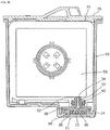
FIG. 5 ,ink filter tower 14 also has a free-floating member such as a metallic,weighted slider 80 installed withinink filter tower 14 in order to prevent ink from from settling withintower 14.Slider 80 is free-floating in the sense that it is not physically connected to the other elements intower 14.Slider 80 is installed in the ink filter tower before the welding of theink filter 30 aboveink filter tower 14. Thereafter, felt or foam is installed inink filter reservoir 50 that is attached aboveink filter 20. After the felt or foam is installed, ink is injected into the reservoir and passes into the ink filter tower. -
Slider 80 is generally comprised of a bridgingmember 88, such as a connecting bar or rod at its upper side, and multiple rectangular-shapedvertical shafts member 88 that connects the shafts.Shafts -
Slider 80 is positioned inink filter tower 14 so that at least some of theshafts trenches shaft 86 may sit inchamber 75adjacent passage 83 but outside of the trenches. The configuration and weight of the bridgingmember 88 and the shafts constrainsslider 80 in a free-floating position relative to the pillars to enable substantially lateral movement from side to side of the printhead assembly without twisting or getting stuck. The ink inchamber 75 acts as a lubricant that enables the slider to move from side to side back and forth within the ink filter tower, but the viscosity of the ink also slows the movement of the slider so that it does not move too rapidly. - The movement of
slider 80 from side to side is initiated by the reciprocating motion of the printhead carrier during printing. The direction of motion of theslider 80 is opposite to the direction of motion of the printhead assembly. Thus, as illustrated inFIG. 6(a) , when the carrier moves to the right,slider 80 moves to the left. Likewise, as illustrated inFIG. 6(b) , when the carrier moves to the left,slider 80 moves to the right. This helps to agitate the ink within the ink filter tower, including the ink near and around the nozzle plate area, to mitigate the settling of ink that would otherwise occur. The ink agitation also helps to mix the ink that may have already settled, such as after a period of non-use of the printer. - In terms of speed, the carrier of an inkjet printer may move at, for example, 30 inches / second and generate 600 pixels / inch. This enables a carrier to function at around 18 kHz = (30 inches / second) x (600 pixels / inch) = 18,000 pixels / second. At these carrier speeds, a slider may move in a direction opposite to the reciprocating direction of the carrier at, for example, 14-15 inches / second. In addition to the carrier speed, the speed of the slider may depend on factors such as the weight of the slider and the composition of the ink. However, the actual speed of slider movement is not limited to any particular value.
- An ink filter tower of this design is particularly useful for pigmented inks where ink settling is a problem. Currently, only mono ink, i.e., black ink, is typically pigmented for use with inkjet printers. However, the present invention would also be useful with pigmented ink of other colors.
-
Slider 80 may be formed from a metallic material, such as stainless steel, and may be encapsulated or coated so as to prevent the metal from being in direct contact with the ink, should the ink used deleteriously interact with the metal. - The
slider 80 is weighted so as to promote movement of the slider within the ink filter tower. In an embodiment, the weight of the slider is approximately in the range of 0.45 to 0.5 grams. -
FIG. 7 shows a perspective view of a first embodiment ofslider 80 according to the present invention. In this embodiment, slider 80' has a bridging member with a substantially flat upper surface 88' and downward-facing shafts 84', 85', and 86' separated bychannels chamber 75 to accommodate a shaft of a larger cross-section for maximum agitation of the ink. In the illustrated embodiment, the perimeters of the bridging member 81' and the vertical edges of the shafts may be beveled to enhance the motion of the slider and prevent the slider from getting stuck. -
FIG. 8 shows a perspective view of a second embodiment ofslider 80 according to the present invention. In this embodiment,slider 80" has a bridging member with a curvedupper surface 88" andshafts 84", 85" and 86" that are columnar in shape with a rectangular cross-section. As with the embodiment shown inFIG. 7 ,shaft 86" may be wider thanshafts 84" and 85" and the edges of theslider 80" may be beveled. -
FIG. 9 shows a perspective view of a third embodiment ofslider 80 according to the present invention. In this embodiment, slider 80''' is shaped as a cam shaft where bridging member 88''' is a rod and shafts 84''', 85''' and 86''' are shaped as circular sectors in cross-section. The side walls of 84''', 85''' and 86''' remain substantially parallel to one another. This design adds an additional degree of freedom to the motion of the free-floating slider so that the slider 88''' not only slides across thepillars FIG. 10 shows a perspective view of the slider 80''' according to the third embodiment as viewed at line X-X ofFIG. 9 . -
FIGs. 11 to 13 shows examples of possible dimensions (in units of mm) for the three different embodiments of aslider 80, shown inFIGs. 7 to 9 . -
FIG. 11A is a side elevational view of the slider ofFIG. 7 in accordance with the first embodiment of the present invention.FIG. 11B is a top view of the slider ofFIG. 11A. FIG. 11C is a cross-sectional view of the slider along line XI-XI ofFIG. 11B . -
FIG. 12A is a side elevational view of the slider ofFIG. 8 in accordance with a second embodiment of the present invention.FIG. 12B is a top view of the slider ofFIG. 12A. FIG. 12C is a cross-sectional view of the slider along line XII-XII ofFIG. 12A. FIG. 12D is a side view of the slider ofFIG. 12A . -
FIG. 13A is a side elevational view of the slider ofFIG. 9 in accordance with a third embodiment of the present invention.FIG. 13B is a top view of the slider ofFIG. 13A. FIG. 13C is a cross-sectional view of the slider along line XIII-XIII ofFIG. 13A. FIG. 13D is a side view of the slider ofFIG. 13A . - The present invention thus serves to agitate the ink in the ink filter tower, and thereby reduces nozzle outages on the printhead assembly and enables a darker coloration of the printed samples.
- While particular embodiments of the invention have been illustrated and described, it would be obvious to those skilled in the art that various other changes and modifications may be made without departing from the spirit and scope of the invention. It is therefore intended to cover in the appended claims all such changes and modifications that are within the scope of this invention.
- The invention also comprises the following Embodiments:
- [Embodiment 1]
A printhead assembly, comprising:- an ink cartridge body;
- an ink reservoir disposed within the ink cartridge body and adapted to receive and contain ink;
a filter disposed adjacent the ink reservoir to filter ink supplied from the ink reservoir as the ink passes through the filter; - a printhead chip provided on the ink cartridge body and in fluid communication with the ink reservoir so as to receive the filtered ink for ejection of the ink onto a print medium;
an ink filter tower disposed between the filter and the printhead chip, the ink filter tower comprising:- an ink entrance passage that receives the filtered ink;
- a chamber that holds the filtered ink received through the ink entrance passage;
- a plurality of extending elements disposed within the chamber, the filtered ink passing through the chamber and around the plurality of extending elements, wherein the extending elements are spaced apart from, and are substantially parallel to, one another;
- a plurality of trenches disposed within the chamber, wherein the plurality of trenches are defined by the extending elements; and
- a free-floating member positioned within the ink filter tower that agitates the filtered ink within the ink filter tower, the member comprising a bridging member and a plurality of shafts extending from the bridging member substantially parallel to one another.
- [Embodiment 2]
The printhead assembly ofEmbodiment 1, wherein the free-floating member is positioned within the ink filter tower such that the bridging member is situated above the extending elements and at least one of the plurality of shafts is situated within one of the plurality of trenches such that the free-floating member is slidable with the ink filter tower in an opposite direction to a direction of motion of the printhead assembly to agitate the filtered ink within the ink filter tower. - [Embodiment 3]
The printhead assembly ofEmbodiment 2, wherein the free-floating member is further positioned within the ink filter tower such that at least a second one of the plurality of shafts is situated within the chamber of the ink filter tower but outside the plurality of trenches. - [Embodiment 4]
The printhead assembly ofEmbodiment 2, wherein the free-floating member is weighted to maintain the positioning of the shafts within the trenches. - [Embodiment 5]
The printhead assembly ofEmbodiment 1, wherein the free-floating member is made of stainless steel. - [Embodiment 6]
The printhead assembly ofEmbodiment 1, wherein the free-floating member is lubricated for movement by the filtered ink when the filtered ink fills the ink filter tower. - [Embodiment 7]
The printhead assembly of Embodiment, 1, wherein the bridging member of the free-floating member comprises a bar with a substantially flat upper surface, and wherein the plurality of shafts comprise columns of a rectangular cross-section. - [Embodiment 8]
The printhead assembly of Embodiment, 1, wherein the bridging member of the free-floating member comprises a curved upper surface and wherein the plurality of shafts comprise columns of a rectangular cross-section. - [Embodiment 9]
The printhead assembly of Embodiment, 1, wherein the free-floating member is shaped as a cam shaft wherein the bridging member of the free-floating member comprises a rod that permits the free-floating member to pivot and slide, and wherein the plurality of shafts are also rotatable about an axis formed by the rod in addition to being slidable. - [Embodiment 10]
The printhead assembly ofEmbodiment 1, wherein the bridging member and
the shafts have beveled edges. - [Embodiment 11]
An inkjet printer comprising:- a housing;
- a carriage adapted to reciprocate along a printer shaft disposed within the housing;
- one or more printhead assemblies arranged on the carriage so that the printhead assemblies eject ink onto a print medium as the carriage reciprocates along the shaft in accordance with a control mechanism, wherein at least one of the one or more printhead assemblies comprises:
- an ink cartridge body;
- an ink reservoir disposed within the ink cartridge body and adapted to receive and contain ink;
- a filter disposed adjacent the ink reservoir to filter ink supplied from the ink reservoir as the ink passes through the filter;
- a printhead chip provided on the ink cartridge body and in fluid communication with the ink reservoir so as to receive the filtered ink for ejection of the ink onto a print medium;
- an ink filter tower disposed between the filter and the printhead chip, the ink filter tower comprising:
- an ink entrance passage that receives the filtered ink;
- a chamber that holds the filtered ink received through the ink entrance passage,
- a plurality of extending elements disposed within the chamber, through which the filtered ink passes to the printhead chip, the filtered ink passing through the chamber and around the plurality of extending elements, wherein the extending elements are spaced apart from, and are substantially parallel to, one another;
- a plurality of trenches disposed within the chamber, wherein the plurality of trenches are defined by the extending elements; and
- a free-floating member positioned within the ink filter tower that agitates the filtered ink within the ink filter tower, the free-floating member comprising a bridging member and a plurality of shafts extending from the bridging member substantially parallel to one another.
- [Embodiment 12]
The inkjet printer ofEmbodiment 11, wherein the free-floating member is positioned within the ink filter tower such that the bridging member is situated above the extending elements and at least one of the plurality of shafts is situated within one of the plurality of trenches such that the free-floating member is slidable with the ink filter tower in an opposite direction to a direction of motion of the printhead assembly to agitate the filtered ink within the ink filter tower. - [Embodiment 13]
The inkjet printer ofEmbodiment 12, wherein the free-floating member is further positioned within the ink filter tower such that at least a second one of the plurality of shafts is situated within the chamber of the ink filter tower but outside the plurality of trenches. - [Embodiment 14]
The inkjet printer ofEmbodiment 12, wherein the free-floating member is weighted to maintain the positioning of the shafts within the nozzle trenches. - [Embodiment 15]
The inkjet printer ofEmbodiment 11, wherein the free-floating member is made of stainless steel. - [Embodiment 16]
The inkjet printer ofEmbodiment 11, wherein the free-floating member is lubricated for movement by the filtered ink when the filtered ink fills the ink filter tower. - [Embodiment 17]
The inkjet printer ofEmbodiment 11, wherein the bridging member of the free-floating member comprises a bar with a substantially flat upper surface, and wherein the plurality of shafts comprise columns of a rectangular cross-section. - [Embodiment 18]
The inkjet printer ofEmbodiment 11, wherein the bridging member of the free-floating member comprises a curved upper surface and wherein the plurality of shafts comprise columns of a rectangular cross-section. - [Embodiment 19]
The inkjet printer ofEmbodiment 11, wherein the free-floating member is shaped as a cam shaft wherein the bridging member of the free-floating member comprises a rod that permits the free-floating member to pivot and slide, and wherein the plurality of shafts are also rotatable about an axis formed by the rod in addition to being slidable. - [Embodiment 20]
The inkjet printer ofEmbodiment 11, wherein the bridging member and the shafts have beveled edges. -
- 1: printhead assembly
- 10: ink cartridge body
- 11: print head chip
- 12: chamber
- 14: ink filter tower
- 15: opening
- 20,30: ink filter
- 32: inner passage
- 34: upper passage portion
- 36: lower passage portion
- 40: gasket
- 50: ink reservoir
- 52: exit port
- 60: fill ball
- 70: lid
- 75: chamber
- 80,80',80",80"': slider
- 81,82,83: pillars
- 84,84',84",84''',85,85',85'',85''',86,86',86",86''': shaft
- 87a,87b: channel
- 88,88''': bridging member
- 88',88": upper surface
- 89,90: trenches
- 101: printhead
- 127: housing
- 161: lid
- 163: body
- 171: interface
- 181,221: surface
- 201: TAB circuit
- 211: portion
- 231: edge
- 241: I/O connector
- 251: heater chip
- 261: electrical conductor
- 281: bond pad
- 321: ink via
- 401: printer
- 421: carriage
- 441: slot
- 431: print zone
- 481: shaft
- 501: drive belt
- 521: paper
- 541: input tray
- 561: output tray
- 571: controller
- 581: control panel
- 591: output
- 601: user selection interface
- 621: input
Claims (15)
- An inkjet cartridge, comprising:a) an ink cartridge body (10);b) an ink reservoir (50) disposed within the ink cartridge body and adapted to receive and contain ink;c) the ink cartridge body (10) including a tower (14);d1) a chamber (75) inside the tower (14) that holds ink;d2) a plurality of extending elements formed by pillars (81, 82, 83) attached at the bottom of the chamber (75) disposed within the chamber, the ink passing through the chamber and around the plurality of extending elements, wherein the extending elements are spaced apart from, and are substantially parallel to, one another;d3) a plurality of trenches (89, 90) disposed within the chamber, wherein the plurality of trenches are defined by the spaces between the extending elements; andd4) a free-floating member formed as a slider (80) free floating in the sense that it is not physically connected to other elements in the tower (14) and positioned within the tower (14) that agitates the ink within the tower, the free-floating member (80) comprising a bridging member (88) and a plurality of shafts (84, 85, 86) protruding from the bridging member (88) substantially parallel to one another, the shafts (84, 85) situated within the trenches (89, 90) between the extending elements (81, 82, 83) with one shaft (86) arranged in the chamber (75) outside the trenches adjacent to one extending element (83).
- The ink cartridge according to claim 1, the tower (14) further comprising an ink entrance passage that receives the ink.
- The inkjet cartridge of claim 1, wherein at least one of the plurality of shafts (84, 85, 86) defines a width that is different than a width defined by at least another of the plurality of shafts (85, 85, 86).
- The inkjet cartridge of claim 3, wherein the at least one of the plurality of shafts (84, 85, 86) is disposed proximate an end of the tower, and the at least another of the plurality of shafts (84, 85, 86) is disposed proximate an opposite end of the tower.
- The inkjet cartridge of claim 1, wherein the plurality of trenches (89, 90) comprises at least four trenches (89, 90).
- The inkjet cartridge of claim 1, wherein the slider (80) is freely movable with respect to the tower.
- The inkjet cartridge of claim 1, wherein the bridging member (88) comprises a flat upper surface.
- The inkjet cartridge of claim 1, wherein the bridging member (88) comprises a curved upper surface.
- A printhead assembly including the ink cartridge according to one or more of claims 1 to 8, further comprising a housing (127) to which is attached a heater chip (251) containing at least one ink via (321) that fluidly connects to a supply of ink in an interior of the housing.
- The printhead assembly according to claim 9, further comprising:a filter (20, 30) disposed adjacent the ink reservoir to filter ink supplied from the ink reservoir as the ink passes through the filter;a printhead chip (11) provided on the ink cartridge body and in fluid communication with the ink reservoir so as to receive the filtered ink for ejection of the ink onto a print medium.
- The printhead assembly according to claim 9, wherein movement of the slider (80) is initiated by a reciprocating motion of the printhead assembly during printing, wherein a direction of motion of the slider (80) is opposite to the direction of motion of the printhead assembly.
- The printhead assembly according to claim 9 or 11, wherein
the trenches (89, 90) are arranged adjacent one another along an axis that is orthogonal to a printhead assembly movement direction, and
the shafts (84, 85, 86) each corresponding to one of the plurality of trenches (89, 90) and the bridging member (88) being movable in a direction parallel to the printhead movement direction. - The printhead assembly of claim 12, wherein the plurality of shafts (84, 85, 86) are dimensioned along the axis that is orthogonal to the printhead assembly movement direction in correspondence with respective widths of the trenches (89, 90).
- The printhead assembly of claim 12, wherein the plurality of trenches (89, 90) each span a width of the tower along a dimension parallel to the printhead movement direction.
- The printhead assembly of claim 9, further comprising a filter cap (30) engaged with the tower (14) and configured to filter ink entering the chamber (75) of the tower (14) from an interior compartment of the housing (127).
Applications Claiming Priority (3)
| Application Number | Priority Date | Filing Date | Title |
|---|---|---|---|
| US14/516,433 US9308737B1 (en) | 2014-10-16 | 2014-10-16 | Agitating member for ink cartridge |
| EP15850913.3A EP3206880B1 (en) | 2014-10-16 | 2015-10-16 | Printhead assembly and inkjet printer |
| PCT/JP2015/005233 WO2016059806A1 (en) | 2014-10-16 | 2015-10-16 | Printhead assembly and inkjet printer |
Related Parent Applications (1)
| Application Number | Title | Priority Date | Filing Date |
|---|---|---|---|
| EP15850913.3A Division EP3206880B1 (en) | 2014-10-16 | 2015-10-16 | Printhead assembly and inkjet printer |
Publications (2)
| Publication Number | Publication Date |
|---|---|
| EP3795362A1 true EP3795362A1 (en) | 2021-03-24 |
| EP3795362B1 EP3795362B1 (en) | 2023-06-21 |
Family
ID=55643083
Family Applications (2)
| Application Number | Title | Priority Date | Filing Date |
|---|---|---|---|
| EP15850913.3A Active EP3206880B1 (en) | 2014-10-16 | 2015-10-16 | Printhead assembly and inkjet printer |
| EP20199912.5A Active EP3795362B1 (en) | 2014-10-16 | 2015-10-16 | Printhead assembly and inkjet printer |
Family Applications Before (1)
| Application Number | Title | Priority Date | Filing Date |
|---|---|---|---|
| EP15850913.3A Active EP3206880B1 (en) | 2014-10-16 | 2015-10-16 | Printhead assembly and inkjet printer |
Country Status (5)
| Country | Link |
|---|---|
| US (3) | US9308737B1 (en) |
| EP (2) | EP3206880B1 (en) |
| JP (1) | JP6627870B2 (en) |
| CN (2) | CN109624511B (en) |
| WO (1) | WO2016059806A1 (en) |
Families Citing this family (6)
| Publication number | Priority date | Publication date | Assignee | Title |
|---|---|---|---|---|
| US9308737B1 (en) | 2014-10-16 | 2016-04-12 | Funai Electric Co., Ltd. | Agitating member for ink cartridge |
| US10512973B2 (en) * | 2015-07-27 | 2019-12-24 | Tungaloy Corporation | Cutting tool replacement member and cutting tool body |
| CN107726549B (en) * | 2017-09-20 | 2019-10-01 | 青岛海尔空调器有限总公司 | A kind of air-conditioned room real-time humidity projectional technique and air conditioner |
| CN110561917B (en) * | 2019-10-21 | 2020-09-08 | 诸暨易联众创企业管理服务有限公司 | Self-adjusting ink box based on annular crushing |
| CN214215199U (en) | 2020-09-11 | 2021-09-17 | 珠海纳思达企业管理有限公司 | Ink cartridge with printhead |
| US20260175588A1 (en) * | 2022-11-07 | 2026-06-25 | Videojet Technologies Inc. | Case for a printer cartridge and manufacturing method |
Citations (5)
| Publication number | Priority date | Publication date | Assignee | Title |
|---|---|---|---|---|
| EP0759362A2 (en) * | 1995-08-22 | 1997-02-26 | Seiko Epson Corporation | Ink jet head connection unit, ink jet cartridge and method of assembling the ink jet head connection unit |
| JP2004216761A (en) * | 2003-01-16 | 2004-08-05 | Seiko Epson Corp | Ink tank and inkjet printer |
| WO2006005056A2 (en) * | 2004-06-30 | 2006-01-12 | Lexmark International, Inc. | Inkjet printhead with multiple ink reservoirs |
| US20060114304A1 (en) * | 2004-11-29 | 2006-06-01 | Lexmark International, Inc. | Air funneling inkjet printhead |
| US7766470B2 (en) * | 2007-05-23 | 2010-08-03 | Lexmark International, Inc. | Ink jet printhead cartridge having an ink fill access port in fluid communication with the filter tower |
Family Cites Families (22)
| Publication number | Priority date | Publication date | Assignee | Title |
|---|---|---|---|---|
| JPH05131645A (en) * | 1991-11-13 | 1993-05-28 | Seiko Epson Corp | Inkjet recording head |
| JP3431051B2 (en) * | 1996-05-20 | 2003-07-28 | セイコーエプソン株式会社 | Ink jet recording apparatus and ink cartridge |
| US6065828A (en) | 1997-02-26 | 2000-05-23 | Hewlett-Packard Company | Selectable mixing of inkjet ink components |
| US6007176A (en) * | 1998-05-05 | 1999-12-28 | Lexmark International, Inc. | Passive cooling arrangement for a thermal ink jet printer |
| JP2001030513A (en) * | 1999-05-17 | 2001-02-06 | Canon Inc | Ink supply mechanism, ink jet cartridge and ink jet recording apparatus |
| JP2002137411A (en) * | 2000-11-06 | 2002-05-14 | Seiko Epson Corp | ink cartridge |
| JP4149745B2 (en) * | 2002-06-19 | 2008-09-17 | 日本電信電話株式会社 | Authentication access control server device, authentication access control method, authentication access control program, and computer-readable recording medium recording the program |
| JP4586363B2 (en) * | 2003-12-26 | 2010-11-24 | セイコーエプソン株式会社 | Liquid ejector |
| US8070272B2 (en) | 2004-06-16 | 2011-12-06 | Seiko Epson Corporation | Liquid container adapted to be mounted on a carriage to reciprocate together with a liquid ejecting head |
| JP2006044153A (en) * | 2004-08-06 | 2006-02-16 | Seiko Epson Corp | Liquid container and liquid ejecting apparatus |
| JP2006218680A (en) * | 2005-02-09 | 2006-08-24 | Seiko Epson Corp | Liquid ejector |
| ATE420771T1 (en) * | 2005-09-02 | 2009-01-15 | Canon Kk | LIQUID CONTAINER |
| JP4646745B2 (en) | 2005-09-02 | 2011-03-09 | キヤノン株式会社 | Ink tank |
| JP4235633B2 (en) | 2005-09-02 | 2009-03-11 | キヤノン株式会社 | Ink tank and recording device |
| JP4886586B2 (en) * | 2006-05-09 | 2012-02-29 | キヤノン株式会社 | Liquid storage container, head cartridge, inkjet recording apparatus, and liquid storage container stirring method |
| US20080165233A1 (en) | 2007-01-08 | 2008-07-10 | Great Computer Corporation | Ink stirrer for a large ink-jet printer |
| JP4924273B2 (en) * | 2007-08-01 | 2012-04-25 | セイコーエプソン株式会社 | Liquid container |
| JP4502061B2 (en) * | 2008-12-04 | 2010-07-14 | セイコーエプソン株式会社 | Inkjet recording device |
| JP2012035471A (en) * | 2010-08-05 | 2012-02-23 | Seiko Epson Corp | Liquid droplet discharge device |
| JP5728984B2 (en) * | 2011-02-07 | 2015-06-03 | セイコーエプソン株式会社 | Stirring apparatus and liquid ejecting apparatus |
| JP5928512B2 (en) * | 2014-03-31 | 2016-06-01 | セイコーエプソン株式会社 | Liquid ejection device |
| US9308737B1 (en) | 2014-10-16 | 2016-04-12 | Funai Electric Co., Ltd. | Agitating member for ink cartridge |
-
2014
- 2014-10-16 US US14/516,433 patent/US9308737B1/en active Active
-
2015
- 2015-10-16 CN CN201811391716.3A patent/CN109624511B/en not_active Expired - Fee Related
- 2015-10-16 EP EP15850913.3A patent/EP3206880B1/en active Active
- 2015-10-16 JP JP2017519019A patent/JP6627870B2/en not_active Expired - Fee Related
- 2015-10-16 WO PCT/JP2015/005233 patent/WO2016059806A1/en not_active Ceased
- 2015-10-16 CN CN201580056037.9A patent/CN107073965B/en not_active Expired - Fee Related
- 2015-10-16 EP EP20199912.5A patent/EP3795362B1/en active Active
-
2016
- 2016-03-22 US US15/077,486 patent/US9573379B2/en not_active Expired - Fee Related
-
2017
- 2017-01-13 US US15/406,162 patent/US9937723B2/en active Active
Patent Citations (5)
| Publication number | Priority date | Publication date | Assignee | Title |
|---|---|---|---|---|
| EP0759362A2 (en) * | 1995-08-22 | 1997-02-26 | Seiko Epson Corporation | Ink jet head connection unit, ink jet cartridge and method of assembling the ink jet head connection unit |
| JP2004216761A (en) * | 2003-01-16 | 2004-08-05 | Seiko Epson Corp | Ink tank and inkjet printer |
| WO2006005056A2 (en) * | 2004-06-30 | 2006-01-12 | Lexmark International, Inc. | Inkjet printhead with multiple ink reservoirs |
| US20060114304A1 (en) * | 2004-11-29 | 2006-06-01 | Lexmark International, Inc. | Air funneling inkjet printhead |
| US7766470B2 (en) * | 2007-05-23 | 2010-08-03 | Lexmark International, Inc. | Ink jet printhead cartridge having an ink fill access port in fluid communication with the filter tower |
Also Published As
| Publication number | Publication date |
|---|---|
| EP3206880A1 (en) | 2017-08-23 |
| EP3206880A4 (en) | 2018-05-23 |
| US9573379B2 (en) | 2017-02-21 |
| US20160200102A1 (en) | 2016-07-14 |
| CN109624511B (en) | 2020-10-09 |
| US9308737B1 (en) | 2016-04-12 |
| EP3206880B1 (en) | 2020-10-07 |
| JP2017530884A (en) | 2017-10-19 |
| CN107073965A (en) | 2017-08-18 |
| WO2016059806A1 (en) | 2016-04-21 |
| US9937723B2 (en) | 2018-04-10 |
| EP3795362B1 (en) | 2023-06-21 |
| CN107073965B (en) | 2018-12-07 |
| US20170165974A1 (en) | 2017-06-15 |
| CN109624511A (en) | 2019-04-16 |
| JP6627870B2 (en) | 2020-01-08 |
| US20160107450A1 (en) | 2016-04-21 |
Similar Documents
| Publication | Publication Date | Title |
|---|---|---|
| US9937723B2 (en) | Agitating member for ink cartridge | |
| EP3148810B1 (en) | Muzzle for printhead assembly | |
| JP4337500B2 (en) | Liquid ejection device | |
| US9944086B2 (en) | Printhead assembly | |
| US10766272B2 (en) | Fluid ejection device | |
| EP3212409B1 (en) | Fluid ejection device | |
| JP2005074836A (en) | Inkjet head unit | |
| JP2002321382A (en) | Colorant reservoir and image forming apparatus having the same | |
| JP2006218680A (en) | Liquid ejector |
Legal Events
| Date | Code | Title | Description |
|---|---|---|---|
| PUAI | Public reference made under article 153(3) epc to a published international application that has entered the european phase |
Free format text: ORIGINAL CODE: 0009012 |
|
| STAA | Information on the status of an ep patent application or granted ep patent |
Free format text: STATUS: THE APPLICATION HAS BEEN PUBLISHED |
|
| AC | Divisional application: reference to earlier application |
Ref document number: 3206880 Country of ref document: EP Kind code of ref document: P |
|
| AK | Designated contracting states |
Kind code of ref document: A1 Designated state(s): AL AT BE BG CH CY CZ DE DK EE ES FI FR GB GR HR HU IE IS IT LI LT LU LV MC MK MT NL NO PL PT RO RS SE SI SK SM TR |
|
| STAA | Information on the status of an ep patent application or granted ep patent |
Free format text: STATUS: REQUEST FOR EXAMINATION WAS MADE |
|
| 17P | Request for examination filed |
Effective date: 20210924 |
|
| RBV | Designated contracting states (corrected) |
Designated state(s): AL AT BE BG CH CY CZ DE DK EE ES FI FR GB GR HR HU IE IS IT LI LT LU LV MC MK MT NL NO PL PT RO RS SE SI SK SM TR |
|
| GRAP | Despatch of communication of intention to grant a patent |
Free format text: ORIGINAL CODE: EPIDOSNIGR1 |
|
| STAA | Information on the status of an ep patent application or granted ep patent |
Free format text: STATUS: GRANT OF PATENT IS INTENDED |
|
| INTG | Intention to grant announced |
Effective date: 20230214 |
|
| GRAS | Grant fee paid |
Free format text: ORIGINAL CODE: EPIDOSNIGR3 |
|
| GRAA | (expected) grant |
Free format text: ORIGINAL CODE: 0009210 |
|
| STAA | Information on the status of an ep patent application or granted ep patent |
Free format text: STATUS: THE PATENT HAS BEEN GRANTED |
|
| AC | Divisional application: reference to earlier application |
Ref document number: 3206880 Country of ref document: EP Kind code of ref document: P |
|
| AK | Designated contracting states |
Kind code of ref document: B1 Designated state(s): AL AT BE BG CH CY CZ DE DK EE ES FI FR GB GR HR HU IE IS IT LI LT LU LV MC MK MT NL NO PL PT RO RS SE SI SK SM TR |
|
| REG | Reference to a national code |
Ref country code: CH Ref legal event code: EP |
|
| REG | Reference to a national code |
Ref country code: DE Ref legal event code: R096 Ref document number: 602015084312 Country of ref document: DE |
|
| REG | Reference to a national code |
Ref country code: AT Ref legal event code: REF Ref document number: 1580662 Country of ref document: AT Kind code of ref document: T Effective date: 20230715 |
|
| REG | Reference to a national code |
Ref country code: IE Ref legal event code: FG4D |
|
| REG | Reference to a national code |
Ref country code: LT Ref legal event code: MG9D |
|
| REG | Reference to a national code |
Ref country code: NL Ref legal event code: MP Effective date: 20230621 |
|
| PG25 | Lapsed in a contracting state [announced via postgrant information from national office to epo] |
Ref country code: SE Free format text: LAPSE BECAUSE OF FAILURE TO SUBMIT A TRANSLATION OF THE DESCRIPTION OR TO PAY THE FEE WITHIN THE PRESCRIBED TIME-LIMIT Effective date: 20230621 Ref country code: NO Free format text: LAPSE BECAUSE OF FAILURE TO SUBMIT A TRANSLATION OF THE DESCRIPTION OR TO PAY THE FEE WITHIN THE PRESCRIBED TIME-LIMIT Effective date: 20230921 |
|
| REG | Reference to a national code |
Ref country code: AT Ref legal event code: MK05 Ref document number: 1580662 Country of ref document: AT Kind code of ref document: T Effective date: 20230621 |
|
| PG25 | Lapsed in a contracting state [announced via postgrant information from national office to epo] |
Ref country code: RS Free format text: LAPSE BECAUSE OF FAILURE TO SUBMIT A TRANSLATION OF THE DESCRIPTION OR TO PAY THE FEE WITHIN THE PRESCRIBED TIME-LIMIT Effective date: 20230621 Ref country code: NL Free format text: LAPSE BECAUSE OF FAILURE TO SUBMIT A TRANSLATION OF THE DESCRIPTION OR TO PAY THE FEE WITHIN THE PRESCRIBED TIME-LIMIT Effective date: 20230621 Ref country code: LV Free format text: LAPSE BECAUSE OF FAILURE TO SUBMIT A TRANSLATION OF THE DESCRIPTION OR TO PAY THE FEE WITHIN THE PRESCRIBED TIME-LIMIT Effective date: 20230621 Ref country code: LT Free format text: LAPSE BECAUSE OF FAILURE TO SUBMIT A TRANSLATION OF THE DESCRIPTION OR TO PAY THE FEE WITHIN THE PRESCRIBED TIME-LIMIT Effective date: 20230621 Ref country code: HR Free format text: LAPSE BECAUSE OF FAILURE TO SUBMIT A TRANSLATION OF THE DESCRIPTION OR TO PAY THE FEE WITHIN THE PRESCRIBED TIME-LIMIT Effective date: 20230621 Ref country code: GR Free format text: LAPSE BECAUSE OF FAILURE TO SUBMIT A TRANSLATION OF THE DESCRIPTION OR TO PAY THE FEE WITHIN THE PRESCRIBED TIME-LIMIT Effective date: 20230922 |
|
| PG25 | Lapsed in a contracting state [announced via postgrant information from national office to epo] |
Ref country code: FI Free format text: LAPSE BECAUSE OF FAILURE TO SUBMIT A TRANSLATION OF THE DESCRIPTION OR TO PAY THE FEE WITHIN THE PRESCRIBED TIME-LIMIT Effective date: 20230621 |
|
| PG25 | Lapsed in a contracting state [announced via postgrant information from national office to epo] |
Ref country code: SK Free format text: LAPSE BECAUSE OF FAILURE TO SUBMIT A TRANSLATION OF THE DESCRIPTION OR TO PAY THE FEE WITHIN THE PRESCRIBED TIME-LIMIT Effective date: 20230621 |
|
| PG25 | Lapsed in a contracting state [announced via postgrant information from national office to epo] |
Ref country code: ES Free format text: LAPSE BECAUSE OF FAILURE TO SUBMIT A TRANSLATION OF THE DESCRIPTION OR TO PAY THE FEE WITHIN THE PRESCRIBED TIME-LIMIT Effective date: 20230621 |
|
| PG25 | Lapsed in a contracting state [announced via postgrant information from national office to epo] |
Ref country code: IS Free format text: LAPSE BECAUSE OF FAILURE TO SUBMIT A TRANSLATION OF THE DESCRIPTION OR TO PAY THE FEE WITHIN THE PRESCRIBED TIME-LIMIT Effective date: 20231021 |
|
| PG25 | Lapsed in a contracting state [announced via postgrant information from national office to epo] |
Ref country code: SM Free format text: LAPSE BECAUSE OF FAILURE TO SUBMIT A TRANSLATION OF THE DESCRIPTION OR TO PAY THE FEE WITHIN THE PRESCRIBED TIME-LIMIT Effective date: 20230621 Ref country code: SK Free format text: LAPSE BECAUSE OF FAILURE TO SUBMIT A TRANSLATION OF THE DESCRIPTION OR TO PAY THE FEE WITHIN THE PRESCRIBED TIME-LIMIT Effective date: 20230621 Ref country code: RO Free format text: LAPSE BECAUSE OF FAILURE TO SUBMIT A TRANSLATION OF THE DESCRIPTION OR TO PAY THE FEE WITHIN THE PRESCRIBED TIME-LIMIT Effective date: 20230621 Ref country code: PT Free format text: LAPSE BECAUSE OF FAILURE TO SUBMIT A TRANSLATION OF THE DESCRIPTION OR TO PAY THE FEE WITHIN THE PRESCRIBED TIME-LIMIT Effective date: 20231023 Ref country code: IS Free format text: LAPSE BECAUSE OF FAILURE TO SUBMIT A TRANSLATION OF THE DESCRIPTION OR TO PAY THE FEE WITHIN THE PRESCRIBED TIME-LIMIT Effective date: 20231021 Ref country code: ES Free format text: LAPSE BECAUSE OF FAILURE TO SUBMIT A TRANSLATION OF THE DESCRIPTION OR TO PAY THE FEE WITHIN THE PRESCRIBED TIME-LIMIT Effective date: 20230621 Ref country code: EE Free format text: LAPSE BECAUSE OF FAILURE TO SUBMIT A TRANSLATION OF THE DESCRIPTION OR TO PAY THE FEE WITHIN THE PRESCRIBED TIME-LIMIT Effective date: 20230621 Ref country code: CZ Free format text: LAPSE BECAUSE OF FAILURE TO SUBMIT A TRANSLATION OF THE DESCRIPTION OR TO PAY THE FEE WITHIN THE PRESCRIBED TIME-LIMIT Effective date: 20230621 Ref country code: AT Free format text: LAPSE BECAUSE OF FAILURE TO SUBMIT A TRANSLATION OF THE DESCRIPTION OR TO PAY THE FEE WITHIN THE PRESCRIBED TIME-LIMIT Effective date: 20230621 |
|
| PGFP | Annual fee paid to national office [announced via postgrant information from national office to epo] |
Ref country code: DE Payment date: 20230830 Year of fee payment: 9 |
|
| PG25 | Lapsed in a contracting state [announced via postgrant information from national office to epo] |
Ref country code: PL Free format text: LAPSE BECAUSE OF FAILURE TO SUBMIT A TRANSLATION OF THE DESCRIPTION OR TO PAY THE FEE WITHIN THE PRESCRIBED TIME-LIMIT Effective date: 20230621 |
|
| REG | Reference to a national code |
Ref country code: DE Ref legal event code: R097 Ref document number: 602015084312 Country of ref document: DE |
|
| PLBE | No opposition filed within time limit |
Free format text: ORIGINAL CODE: 0009261 |
|
| STAA | Information on the status of an ep patent application or granted ep patent |
Free format text: STATUS: NO OPPOSITION FILED WITHIN TIME LIMIT |
|
| PG25 | Lapsed in a contracting state [announced via postgrant information from national office to epo] |
Ref country code: DK Free format text: LAPSE BECAUSE OF FAILURE TO SUBMIT A TRANSLATION OF THE DESCRIPTION OR TO PAY THE FEE WITHIN THE PRESCRIBED TIME-LIMIT Effective date: 20230621 |
|
| PG25 | Lapsed in a contracting state [announced via postgrant information from national office to epo] |
Ref country code: SI Free format text: LAPSE BECAUSE OF FAILURE TO SUBMIT A TRANSLATION OF THE DESCRIPTION OR TO PAY THE FEE WITHIN THE PRESCRIBED TIME-LIMIT Effective date: 20230621 |
|
| 26N | No opposition filed |
Effective date: 20240322 |
|
| PG25 | Lapsed in a contracting state [announced via postgrant information from national office to epo] |
Ref country code: SI Free format text: LAPSE BECAUSE OF FAILURE TO SUBMIT A TRANSLATION OF THE DESCRIPTION OR TO PAY THE FEE WITHIN THE PRESCRIBED TIME-LIMIT Effective date: 20230621 Ref country code: IT Free format text: LAPSE BECAUSE OF FAILURE TO SUBMIT A TRANSLATION OF THE DESCRIPTION OR TO PAY THE FEE WITHIN THE PRESCRIBED TIME-LIMIT Effective date: 20230621 Ref country code: MC Free format text: LAPSE BECAUSE OF FAILURE TO SUBMIT A TRANSLATION OF THE DESCRIPTION OR TO PAY THE FEE WITHIN THE PRESCRIBED TIME-LIMIT Effective date: 20230621 |
|
| REG | Reference to a national code |
Ref country code: CH Ref legal event code: PL |
|
| REG | Reference to a national code |
Ref country code: BE Ref legal event code: MM Effective date: 20231031 |
|
| PG25 | Lapsed in a contracting state [announced via postgrant information from national office to epo] |
Ref country code: LU Free format text: LAPSE BECAUSE OF NON-PAYMENT OF DUE FEES Effective date: 20231016 |
|
| GBPC | Gb: european patent ceased through non-payment of renewal fee |
Effective date: 20231016 |
|
| PG25 | Lapsed in a contracting state [announced via postgrant information from national office to epo] |
Ref country code: LU Free format text: LAPSE BECAUSE OF NON-PAYMENT OF DUE FEES Effective date: 20231016 |
|
| PG25 | Lapsed in a contracting state [announced via postgrant information from national office to epo] |
Ref country code: GB Free format text: LAPSE BECAUSE OF NON-PAYMENT OF DUE FEES Effective date: 20231016 |
|
| PG25 | Lapsed in a contracting state [announced via postgrant information from national office to epo] |
Ref country code: CH Free format text: LAPSE BECAUSE OF NON-PAYMENT OF DUE FEES Effective date: 20231031 |
|
| PG25 | Lapsed in a contracting state [announced via postgrant information from national office to epo] |
Ref country code: GB Free format text: LAPSE BECAUSE OF NON-PAYMENT OF DUE FEES Effective date: 20231016 Ref country code: FR Free format text: LAPSE BECAUSE OF NON-PAYMENT OF DUE FEES Effective date: 20231031 Ref country code: CH Free format text: LAPSE BECAUSE OF NON-PAYMENT OF DUE FEES Effective date: 20231031 |
|
| PG25 | Lapsed in a contracting state [announced via postgrant information from national office to epo] |
Ref country code: BE Free format text: LAPSE BECAUSE OF NON-PAYMENT OF DUE FEES Effective date: 20231031 |
|
| PG25 | Lapsed in a contracting state [announced via postgrant information from national office to epo] |
Ref country code: IE Free format text: LAPSE BECAUSE OF NON-PAYMENT OF DUE FEES Effective date: 20231016 |
|
| PG25 | Lapsed in a contracting state [announced via postgrant information from national office to epo] |
Ref country code: IE Free format text: LAPSE BECAUSE OF NON-PAYMENT OF DUE FEES Effective date: 20231016 |
|
| PG25 | Lapsed in a contracting state [announced via postgrant information from national office to epo] |
Ref country code: BG Free format text: LAPSE BECAUSE OF FAILURE TO SUBMIT A TRANSLATION OF THE DESCRIPTION OR TO PAY THE FEE WITHIN THE PRESCRIBED TIME-LIMIT Effective date: 20230621 |
|
| PG25 | Lapsed in a contracting state [announced via postgrant information from national office to epo] |
Ref country code: BG Free format text: LAPSE BECAUSE OF FAILURE TO SUBMIT A TRANSLATION OF THE DESCRIPTION OR TO PAY THE FEE WITHIN THE PRESCRIBED TIME-LIMIT Effective date: 20230621 |
|
| REG | Reference to a national code |
Ref country code: DE Ref legal event code: R119 Ref document number: 602015084312 Country of ref document: DE |
|
| PG25 | Lapsed in a contracting state [announced via postgrant information from national office to epo] |
Ref country code: DE Free format text: LAPSE BECAUSE OF NON-PAYMENT OF DUE FEES Effective date: 20250501 |
|
| PG25 | Lapsed in a contracting state [announced via postgrant information from national office to epo] |
Ref country code: CY Free format text: LAPSE BECAUSE OF FAILURE TO SUBMIT A TRANSLATION OF THE DESCRIPTION OR TO PAY THE FEE WITHIN THE PRESCRIBED TIME-LIMIT; INVALID AB INITIO Effective date: 20151016 |
|
| PG25 | Lapsed in a contracting state [announced via postgrant information from national office to epo] |
Ref country code: HU Free format text: LAPSE BECAUSE OF FAILURE TO SUBMIT A TRANSLATION OF THE DESCRIPTION OR TO PAY THE FEE WITHIN THE PRESCRIBED TIME-LIMIT; INVALID AB INITIO Effective date: 20151016 |
|
| PG25 | Lapsed in a contracting state [announced via postgrant information from national office to epo] |
Ref country code: TR Free format text: LAPSE BECAUSE OF FAILURE TO SUBMIT A TRANSLATION OF THE DESCRIPTION OR TO PAY THE FEE WITHIN THE PRESCRIBED TIME-LIMIT Effective date: 20230621 |