EP3795289A1 - Oxidation resistant nickel braze putty - Google Patents
Oxidation resistant nickel braze putty Download PDFInfo
- Publication number
- EP3795289A1 EP3795289A1 EP20196225.5A EP20196225A EP3795289A1 EP 3795289 A1 EP3795289 A1 EP 3795289A1 EP 20196225 A EP20196225 A EP 20196225A EP 3795289 A1 EP3795289 A1 EP 3795289A1
- Authority
- EP
- European Patent Office
- Prior art keywords
- nickel alloy
- braze
- nickel
- putty
- amount
- Prior art date
- Legal status (The legal status is an assumption and is not a legal conclusion. Google has not performed a legal analysis and makes no representation as to the accuracy of the status listed.)
- Granted
Links
Images

Classifications
-
- B—PERFORMING OPERATIONS; TRANSPORTING
- B22—CASTING; POWDER METALLURGY
- B22F—WORKING METALLIC POWDER; MANUFACTURE OF ARTICLES FROM METALLIC POWDER; MAKING METALLIC POWDER; APPARATUS OR DEVICES SPECIALLY ADAPTED FOR METALLIC POWDER
- B22F7/00—Manufacture of composite layers, workpieces, or articles, comprising metallic powder, by sintering the powder, with or without compacting wherein at least one part is obtained by sintering or compression
- B22F7/06—Manufacture of composite layers, workpieces, or articles, comprising metallic powder, by sintering the powder, with or without compacting wherein at least one part is obtained by sintering or compression of composite workpieces or articles from parts, e.g. to form tipped tools
- B22F7/062—Manufacture of composite layers, workpieces, or articles, comprising metallic powder, by sintering the powder, with or without compacting wherein at least one part is obtained by sintering or compression of composite workpieces or articles from parts, e.g. to form tipped tools involving the connection or repairing of preformed parts
-
- B—PERFORMING OPERATIONS; TRANSPORTING
- B22—CASTING; POWDER METALLURGY
- B22F—WORKING METALLIC POWDER; MANUFACTURE OF ARTICLES FROM METALLIC POWDER; MAKING METALLIC POWDER; APPARATUS OR DEVICES SPECIALLY ADAPTED FOR METALLIC POWDER
- B22F1/00—Metallic powder; Treatment of metallic powder, e.g. to facilitate working or to improve properties
- B22F1/09—Mixtures of metallic powders
-
- B—PERFORMING OPERATIONS; TRANSPORTING
- B22—CASTING; POWDER METALLURGY
- B22F—WORKING METALLIC POWDER; MANUFACTURE OF ARTICLES FROM METALLIC POWDER; MAKING METALLIC POWDER; APPARATUS OR DEVICES SPECIALLY ADAPTED FOR METALLIC POWDER
- B22F1/00—Metallic powder; Treatment of metallic powder, e.g. to facilitate working or to improve properties
- B22F1/10—Metallic powder containing lubricating or binding agents; Metallic powder containing organic material
-
- B—PERFORMING OPERATIONS; TRANSPORTING
- B22—CASTING; POWDER METALLURGY
- B22F—WORKING METALLIC POWDER; MANUFACTURE OF ARTICLES FROM METALLIC POWDER; MAKING METALLIC POWDER; APPARATUS OR DEVICES SPECIALLY ADAPTED FOR METALLIC POWDER
- B22F1/00—Metallic powder; Treatment of metallic powder, e.g. to facilitate working or to improve properties
- B22F1/10—Metallic powder containing lubricating or binding agents; Metallic powder containing organic material
- B22F1/107—Metallic powder containing lubricating or binding agents; Metallic powder containing organic material containing organic material comprising solvents, e.g. for slip casting
-
- B—PERFORMING OPERATIONS; TRANSPORTING
- B23—MACHINE TOOLS; METAL-WORKING NOT OTHERWISE PROVIDED FOR
- B23K—SOLDERING OR UNSOLDERING; WELDING; CLADDING OR PLATING BY SOLDERING OR WELDING; CUTTING BY APPLYING HEAT LOCALLY, e.g. FLAME CUTTING; WORKING BY LASER BEAM
- B23K1/00—Soldering, e.g. brazing, or unsoldering
- B23K1/20—Preliminary treatment of work or areas to be soldered, e.g. in respect of a galvanic coating
-
- B—PERFORMING OPERATIONS; TRANSPORTING
- B23—MACHINE TOOLS; METAL-WORKING NOT OTHERWISE PROVIDED FOR
- B23K—SOLDERING OR UNSOLDERING; WELDING; CLADDING OR PLATING BY SOLDERING OR WELDING; CUTTING BY APPLYING HEAT LOCALLY, e.g. FLAME CUTTING; WORKING BY LASER BEAM
- B23K35/00—Rods, electrodes, materials, or media, for use in soldering, welding, or cutting
- B23K35/02—Rods, electrodes, materials, or media, for use in soldering, welding, or cutting characterised by mechanical features, e.g. shape
- B23K35/0222—Rods, electrodes, materials, or media, for use in soldering, welding, or cutting characterised by mechanical features, e.g. shape for use in soldering or brazing
- B23K35/0244—Powders, particles or spheres; Preforms made therefrom
- B23K35/025—Pastes, creams or slurries
-
- B—PERFORMING OPERATIONS; TRANSPORTING
- B23—MACHINE TOOLS; METAL-WORKING NOT OTHERWISE PROVIDED FOR
- B23K—SOLDERING OR UNSOLDERING; WELDING; CLADDING OR PLATING BY SOLDERING OR WELDING; CUTTING BY APPLYING HEAT LOCALLY, e.g. FLAME CUTTING; WORKING BY LASER BEAM
- B23K35/00—Rods, electrodes, materials, or media, for use in soldering, welding, or cutting
- B23K35/22—Rods, electrodes, materials, or media, for use in soldering, welding, or cutting characterised by the composition or nature of the material
- B23K35/24—Selection of soldering or welding materials proper
- B23K35/30—Selection of soldering or welding materials proper with the principal constituent melting at less than 1550°C
- B23K35/3033—Ni as the principal constituent
- B23K35/304—Ni as the principal constituent with Cr as the next major constituent
-
- B—PERFORMING OPERATIONS; TRANSPORTING
- B23—MACHINE TOOLS; METAL-WORKING NOT OTHERWISE PROVIDED FOR
- B23P—METAL-WORKING NOT OTHERWISE PROVIDED FOR; COMBINED OPERATIONS; UNIVERSAL MACHINE TOOLS
- B23P6/00—Restoring or reconditioning objects
-
- C—CHEMISTRY; METALLURGY
- C22—METALLURGY; FERROUS OR NON-FERROUS ALLOYS; TREATMENT OF ALLOYS OR NON-FERROUS METALS
- C22C—ALLOYS
- C22C19/00—Alloys based on nickel or cobalt
- C22C19/03—Alloys based on nickel or cobalt based on nickel
- C22C19/05—Alloys based on nickel or cobalt based on nickel with chromium
- C22C19/051—Alloys based on nickel or cobalt based on nickel with chromium and Mo or W
- C22C19/057—Alloys based on nickel or cobalt based on nickel with chromium and Mo or W with the maximum Cr content being less 10%
-
- B—PERFORMING OPERATIONS; TRANSPORTING
- B22—CASTING; POWDER METALLURGY
- B22F—WORKING METALLIC POWDER; MANUFACTURE OF ARTICLES FROM METALLIC POWDER; MAKING METALLIC POWDER; APPARATUS OR DEVICES SPECIALLY ADAPTED FOR METALLIC POWDER
- B22F7/00—Manufacture of composite layers, workpieces, or articles, comprising metallic powder, by sintering the powder, with or without compacting wherein at least one part is obtained by sintering or compression
- B22F7/06—Manufacture of composite layers, workpieces, or articles, comprising metallic powder, by sintering the powder, with or without compacting wherein at least one part is obtained by sintering or compression of composite workpieces or articles from parts, e.g. to form tipped tools
- B22F7/062—Manufacture of composite layers, workpieces, or articles, comprising metallic powder, by sintering the powder, with or without compacting wherein at least one part is obtained by sintering or compression of composite workpieces or articles from parts, e.g. to form tipped tools involving the connection or repairing of preformed parts
- B22F2007/068—Manufacture of composite layers, workpieces, or articles, comprising metallic powder, by sintering the powder, with or without compacting wherein at least one part is obtained by sintering or compression of composite workpieces or articles from parts, e.g. to form tipped tools involving the connection or repairing of preformed parts repairing articles
-
- B—PERFORMING OPERATIONS; TRANSPORTING
- B23—MACHINE TOOLS; METAL-WORKING NOT OTHERWISE PROVIDED FOR
- B23K—SOLDERING OR UNSOLDERING; WELDING; CLADDING OR PLATING BY SOLDERING OR WELDING; CUTTING BY APPLYING HEAT LOCALLY, e.g. FLAME CUTTING; WORKING BY LASER BEAM
- B23K35/00—Rods, electrodes, materials, or media, for use in soldering, welding, or cutting
- B23K35/02—Rods, electrodes, materials, or media, for use in soldering, welding, or cutting characterised by mechanical features, e.g. shape
- B23K35/0222—Rods, electrodes, materials, or media, for use in soldering, welding, or cutting characterised by mechanical features, e.g. shape for use in soldering or brazing
- B23K35/0244—Powders, particles or spheres; Preforms made therefrom
-
- B—PERFORMING OPERATIONS; TRANSPORTING
- B23—MACHINE TOOLS; METAL-WORKING NOT OTHERWISE PROVIDED FOR
- B23K—SOLDERING OR UNSOLDERING; WELDING; CLADDING OR PLATING BY SOLDERING OR WELDING; CUTTING BY APPLYING HEAT LOCALLY, e.g. FLAME CUTTING; WORKING BY LASER BEAM
- B23K35/00—Rods, electrodes, materials, or media, for use in soldering, welding, or cutting
- B23K35/22—Rods, electrodes, materials, or media, for use in soldering, welding, or cutting characterised by the composition or nature of the material
- B23K35/24—Selection of soldering or welding materials proper
- B23K35/30—Selection of soldering or welding materials proper with the principal constituent melting at less than 1550°C
- B23K35/3033—Ni as the principal constituent
-
- B—PERFORMING OPERATIONS; TRANSPORTING
- B23—MACHINE TOOLS; METAL-WORKING NOT OTHERWISE PROVIDED FOR
- B23K—SOLDERING OR UNSOLDERING; WELDING; CLADDING OR PLATING BY SOLDERING OR WELDING; CUTTING BY APPLYING HEAT LOCALLY, e.g. FLAME CUTTING; WORKING BY LASER BEAM
- B23K35/00—Rods, electrodes, materials, or media, for use in soldering, welding, or cutting
- B23K35/22—Rods, electrodes, materials, or media, for use in soldering, welding, or cutting characterised by the composition or nature of the material
- B23K35/36—Selection of non-metallic compositions, e.g. coatings or fluxes; Selection of soldering or welding materials, conjoint with selection of non-metallic compositions, both selections being of interest
- B23K35/3612—Selection of non-metallic compositions, e.g. coatings or fluxes; Selection of soldering or welding materials, conjoint with selection of non-metallic compositions, both selections being of interest with organic compounds as principal constituents
- B23K35/3613—Polymers, e.g. resins
Definitions
- Exemplary embodiments pertain to the art of braze materials.
- melt casting is used to fabricate intricate designs that forging or wrought alloy processing cannot produce.
- cast parts can contain defects that are artifacts of the casting process. These defects can be removed by mechanical means and the part repaired to yield a defect free part for use. When the defect is large and a substantial amount of material is removed by mechanical means, welding is typically the desired approach but can be unsuccessful depending on the alloy used to form the part. New approaches to repair complex cast parts are needed.
- a braze putty composition (e.g. which can be made according to the method described herein and/or which can be used in a method of repairing a cast part as described herein) including or comprising a binder, e.g. a sacrificial binder, a first nickel alloy and a second nickel alloy.
- a binder e.g. a sacrificial binder, a first nickel alloy and a second nickel alloy.
- the sacrificial binder comprises an acrylic polymer having a glass transition temperature below about 20°C.
- the first nickel alloy includes or comprises up to about 0.02 wt % of boron and the second nickel alloy includes or comprises boron in an amount no greater than 1.0 wt %.
- the first nickel alloy includes or comprises about 4.75 wt %-10.5 wt % of chromium, about 5.5 wt %-6.7 wt % of aluminum, up to about 13 wt % cobalt, about 3.75 wt %-9.0 wt % of tantalum, about 1.3 wt %-2.25 wt % of molybdenum, about 3.0 wt %-6.8 wt % of tungsten, about 2.6 wt %-3.25 wt % of rhenium, up to about 0.02 wt % of boron, about 0.05 wt %-2.0 wt % of hafnium, up to about 0.14 wt % of carbon, up to about 0.35 wt % of zirconium, and a balance of nickel and the second nickel alloy includes or comprises about 21.25
- the first nickel alloy is present in an amount of 20 to 80 weight percent and the second nickel alloy is present in an amount of 20 to 80 weight percent relative to the total amount of the first nickel alloy and the second nickel alloy.
- the first nickel alloy is present in an amount of 60 weight percent and the second nickel alloy is present in an amount of 40 weight percent relative to the total amount of the first nickel alloy and the second nickel alloy.
- the nickel alloys have regularly-shaped particles.
- the nickel alloys are particles and the particles pass through a 325 mesh standard sieve.
- the sacrificial binder is present in an amount of 5 to 8 weight percent of the combined weight of the first nickel alloy and the second nickel alloy.
- braze putty composition as described above comprising: mixing a principle binder polymer with a solvent at a first speed to dissolve the principle binder polymer and form the sacrificial binder; and mixing first nickel alloy particulates and second nickel alloy particulates with the sacrificial binder at a second speed under vacuum, wherein the second speed is less than the first speed.
- a method of repairing a cast part including or comprising mechanically removing a defect or working a damaged area of a cast part to form a repair area; applying a braze putty to the repair area, wherein the braze putty (e.g. as described herein) comprises a binder, e.g. a sacrificial binder, a first nickel alloy and a second nickel alloy; and optionally removing the sacrificial binder and fusing the nickel alloys to the repair area of the cast part.
- the braze putty e.g. as described herein
- the braze putty comprises a binder, e.g. a sacrificial binder, a first nickel alloy and a second nickel alloy; and optionally removing the sacrificial binder and fusing the nickel alloys to the repair area of the cast part.
- the sacrificial binder comprises an acrylic polymer having a glass transition temperature below about 20°C.
- the first nickel alloy comprises up to about 0.02 wt % of boron and the second nickel alloy comprises boron in an amount no greater than 1.0 wt %.
- the first nickel alloy comprises about 4.75 wt %-10.5 wt % of chromium, about 5.5 wt %-6.7 wt % of aluminum, up to about 13 wt % cobalt, about 3.75 wt %-9.0 wt % of tantalum, about 1.3 wt %-2.25 wt % of molybdenum, about 3.0 wt %-6.8 wt % of tungsten, about 2.6 wt %-3.25 wt % of rhenium, up to about 0.02 wt % of boron, about 0.05 wt %-2.0 wt % of hafnium, up to about 0.14 wt % of carbon, up to about 0.35 wt % of zirconium, and a balance of nickel and the second nickel alloy comprises about 21.25 wt %-10.5 wt % of chromium, about 5.5 wt %-6.7
- the first nickel alloy is present in an amount of 20 to 80 weight percent and the second nickel alloy is present in an amount of 20 to 80 weight percent relative to the total amount of the first nickel alloy and the second nickel alloy.
- the first nickel alloy is present in an amount of 60 weight percent and the second nickel alloy is present in an amount of 40 weight percent relative to the total amount of the first nickel alloy and the second nickel alloy.
- the nickel alloys have regularly-shaped particles.
- the nickel alloys are particles and the particles pass through a 325 mesh standard sieve.
- the sacrificial binder is present in an amount of 5 to 8 weight percent of the combined weight of the first nickel alloy and the second nickel alloy.
- Casting defects can include residual casting core material, dross, inclusions, porosity and the like.
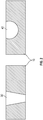
- FIG. 1 shows a cast part 10 having a defect 20. To repair the cast part these defects are removed by mechanical means. Material removal can result in large voids such as through wall voids or dish outs.
- FIG. 2 shows a casting 10 having a through wall void 30 or a dish out 40. The material removed to form the void must be replaced in order to place the part in service. Methods for replacing the material depend on the size of the void. Small voids can be filled by brazing. Brazing with pastes and the like typically utilizes flow and capillary action to draw material into small areas such as cracks and small voids.
- braze putty can be used for large voids but is limited in composition and does not provide sufficient environmental resistance for a true repair of a casting defect. It is expected that repairing a cast defect will produce a part that is equivalent to a cast part without a defect in all aspects, including environmental resistance. The braze putty is also useful for repairing damaged parts.
- Described herein is a braze putty and a method of using it which can be used to repair casting defects and damage to produce a part with environmental resistance equivalent to a cast part without a casting defect.
- the braze putty includes a sacrificial binder system, a first nickel alloy and a second nickel alloy.
- the sacrificial binder system comprises a principle binder polymer and a solvent with a low vapor pressure, preferably less than about 20 mm Hg at 25°C.
- the principle binder polymer is a thermoplastic and has a softening or glass transition temperature (Tg) below about 20°C. Additionally, the sacrificial binder system may contain a plasticizer and a wetting agent.
- Tg softening or glass transition temperature
- the sacrificial binder system may contain a plasticizer and a wetting agent.
- the low glass transition temperature of the principle binder polymer makes it soft and malleable at room temperature, while the low vaporization rate of the solvent contributes to wet tack, adhesion and a useful working life. When combined with alloy powders, these binder properties result in a braze putty with a consistency somewhat like modelling clay or adhesive putty.
- the principle binder polymer may comprise an acrylic polymer or blend of acrylic polymers which provide a balance of cohesive strength or rigidity and softness or flexibility.
- a tough, hard polymer which has good strength and a high softening temperature can be plasticized with a softer, more flexible polymer to give the desired properties.
- the glass transition temperature of the principle binder polymer is low enough, it may even have a slight tacky feel even before solvents and plasticizers are added.
- Acrylic polymers have other desirable properties which make them useful as ingredients in the sacrificial binder system. For example, acrylic polymers remain stable above their softening range at temperatures up to 170-230° C.
- acrylic polymers are methacrylate, methyl methacrylate, ethyl methacrylate, n-butyl methacrylate, isobutyl methacrylate, methyl/n-butyl methacrylate, n-butyl/isobutyl methacrylate, methyl/laurel methacrylate polymers and copolymers. It is preferred that the principle binder polymer make up 25-50% by weight of the sacrificial binder system and most preferably 30-40% of the sacrificial binder system.
- the solvent used in conjunction with the sacrificial binder must be active, which is to say that it is capable of dissolving the principle binder polymer. Initially, the solvent contributes to the wet tackiness, softness, and moldability of the sacrificial binder system. After the braze putty has been applied to an article to be repaired or joined, the principle binder polymer is dried and hardened by evaporation of the solvent. Thus, the solvent must have a low volatility at room temperature in order to provide a useful working life (e.g. several hours) once it is exposed to the atmosphere, but substantially vaporize when heated to temperatures up to 200° C.
- the solvent When used in conjunction with the principle binder polymer, it is desirable that the solvent have a vapor pressure below 20 mm Hg at ambient temperature or below 1 mm Hg at ambient temperature.
- the solvent must vaporize completely and cleanly during air drying and vacuum furnace burn-out.
- Solvents which are useful in the sacrificial binder system are esters such as isoamyl acetate and isobutyl acetate, hydrocarbons, such as VM&P naptha and mineral spirits, and glycol ethers and acetates such as propylene glycol methyl ether, dipropylene glycol methyl ether, tripropylene glycol methyl ether, propylene glycol methyl ether acetate and dipropylene glycol methyl ether acetate.
- the solvent may make up 25-60% by weight or 30-45% by weight of the sacrificial binder system.
- the sacrificial binder system may optionally contain a plasticizer.
- the plasticizer further lowers the softening temperature of the principle binder polymer and provides added flexibility, softness and adhesion.
- the plasticizer must be chemically compatible (i.e. form solutions) with the principle binder polymer and solvent, sufficiently volatile to allow its removal during the vacuum furnace binder burn-out process, but not sufficiently volatile to be substantially removed during mixing, storage, molding or air drying.
- the plasticizer must further completely decompose into gaseous, volatile species at high temperatures without leaving substantial level of solid residue.
- Exemplary plasticizers include phthalic and adipic esters.
- phthalic esters which can be used to plasticize the acrylic principle binder polymers are alkyl benzyl phthalate, butyl benzyl phthalate, butyl octyl phthalate, dibutyl phthalate, dicyclohexyl phthalate, diethylphthalate, dihexyl phthalate, diisodecyl phthalate, di-2-methoxyethyl phthalate, dimethyl phthalate, ditridecyl phthalate, di-2-ethylhexyl phthalate, diisooctyl and mixed octyl phthalate, n-octyl n-decyl phthalate and isooctyl isodecyl phthalate.
- adipic esters which can be used to plasticize acrylic polymers are dioctyl adipate, diisodecyl adipate, di-2-ethylhexyl adipate, octyl decyl adipate, diisobutyl adipate and diisooctyl adipate.
- the plasticizer may make up 0-30% by weight or 15-25% by weight of the sacrificial binder system.
- the sacrificial binder polymer may, optionally, contain a wetting agent.
- the wetting agent lowers the surface tension of the binder system, promoting adhesion to the repair cavity or joint surfaces and dispersion of powder particles.
- the wetting agent must also be compatible with the other binder ingredients and burn out cleanly from the filler material leaving negligible ash or solid deposits.
- Exemplary wetting agents include nonyl or octyl phenol base nonionic surfactants. Some examples of nonyl phenol based surfactants are nonylphenol polyethylene glycol ether and nonylphenoxypolyethoxyethanol nonionic surfactant.
- octyl phenol base surfactant is octylphenoxypolyethoxyethanol nonionic surfactant.
- the wetting agent may make up 0-5% by weight of the sacrificial binder system and preferably 1-2% by weight of the sacrificial binder system.
- the first nickel alloy may be a high melting temperature nickel alloy and the second nickel alloy may be a low melting temperature nickel alloy relative to the high melting temperature nickel alloy. That is, the first nickel alloy is a different chemical composition than the second nickel alloy. For instance, the first nickel alloy may have an equivalent composition to the nickel alloy substrate intended to for repair.
- the first nickel alloy includes up to about 0.02 wt % of boron and the second nickel alloy includes boron in an amount no greater than 1.0 wt %. Boron contributes to lowering the melting temperature of nickel alloys but may be detrimental to forming a stable oxide scale relative to the nickel alloy substrate.
- using the relatively low level of boron in the second nickel alloy provides the benefit of a lower melting temperature for the brazing process and a combined composition of the blend that is relatively low in boron and capable of forming a stable oxide scale that functions as an oxygen barrier for enhanced environmental resistance.
- the second nickel alloy may include about 0.45 wt %-0.55 wt % of boron, based on the total weight of the alloy to provide an even more stable oxide scale.
- the first nickel alloy and the second nickel alloy may be of a variety of different compositions to facilitate enhanced environmental resistance.
- the first nickel alloy may include about 4.75 wt %-10.5 wt % of chromium, about 5.5 wt %-6.7 wt % of aluminum, up to about 13 wt % cobalt, about 3.75 wt %-9.0 wt % of tantalum, about 1.3 wt %-2.25 wt % of molybdenum, about 3.0 wt %-6.8 wt % of tungsten, about 2.6 wt %-3.25 wt % of rhenium, up to about 0.02 wt % of boron, about 0.05 wt %-2.0 wt % of hafnium, up to about 0.14 wt % of carbon, up to about 0.35 wt % of zirconium, and a balance of nickel.
- the second nickel alloy may include about 21.25 wt %-22.75 wt % of chromium, about 5.7 wt %-6.3 wt % of aluminum, about 11.5 wt %-12.5 wt % of cobalt, about 5.7 wt %-6.3 wt % of silicon, boron in an amount no greater than 1.0 wt % or 0.45 wt %-0.55 wt % of boron as described above, and a balance of nickel.
- any of the compositions of this disclosure may include other elements.
- any of the compositions of this disclosure may include only the elements listed in the particular composition.
- the compositions may include only other impurity elements that do not affect the properties of the alloy, such as oxidation tendencies, or elements that are unmeasured or undetectable in the alloy.
- the first nickel alloy may be any of the example compositions 1-5 in Table I below.
- the first nickel alloy may be any of the example compositions 6-10 in Table II below
- the second nickel alloy may be the example composition 11 in Table II.
- the blend may include 20 wt %-80 wt % of the first nickel alloy and 20 wt %-80 wt % of the second nickel alloy.
- the blend may exclusively include the first nickel alloy and the second nickel alloy such that the sum of the selected amounts totals 100 wt %.
- the blend may include only the first nickel alloy, the second nickel alloy, and a binder material.
- the blend may include other constituents, but relative to a total amount of the first nickel alloy and the second nickel alloy, the blend includes 20 wt %-80 wt % of the first nickel alloy and 20 wt %-80 wt % of the second nickel alloy.
- the blend may include any ratio of the first nickel alloy and the second nickel alloy (e.g, depending on the desired combined alloy composition, brazing process, or other parameters).
- the blend may include about 40 wt % of the first nickel alloy and about 60 wt % of the second nickel alloy, about 60 wt % of the first nickel alloy and about 40 wt % of the second nickel alloy, about 20 wt % of the first nickel alloy and about 80 wt % of the second nickel alloy, or about 80 wt % of the first nickel alloy and about 20 wt % of the second nickel alloy.
- the blend having about 60 wt % of the first nickel alloy and about 40 wt % of the second nickel alloy exhibits a desirable balance of braze processability and environmental resistance. Given this description, one of ordinary skill in the art will recognize desirable ratios of the first nickel alloy and the second nickel alloy to meet their particular needs.
- the blend may have a variety of different combined alloy compositions, depending on the blend ratio and compositions of the first braze alloy and the second braze alloy.
- the combined alloy composition may include about 8 wt %-20.3 wt % of chromium, about 5.5 wt %-6.7 wt % of aluminum, about 2.3 wt %-12.9 wt % of cobalt, about 0.7 wt %-7.2 wt % of tantalum, about 0.25 wt %-1.8 wt % of molybdenum, about 0.6 wt %-5.5 wt % of tungsten, up to 2.6 wt % of rhenium, about 1.1 wt %-5.1 wt % of silicon, boron in an amount no greater than 0.8 wt %, hafnium in an amount no greater than 1.6 wt %, up to about 0.12 wt % of carbon, up to about 0.3 wt %
- the combined alloy composition of the blend may be any of the example compositions 12-15 in Table III below.
- Table III Element Combined Alloy Powder Composition (wt %) 12 13 14 15 Cr 11.35-15.4 14.6-17.9 17.9-20.3 8.0-13.0 Al.
- the blend includes about 60 wt % of the first nickel alloy and about 40 wt % of the second nickel alloy and may have any of the example compositions 16-20 in Table IV below.
- Table IV TABLE IV Element 60 wt % First Powder/40 wt % Second Powder Combined Composition (wt %) 16 17 18 19 20 Cr 12.46-13.3 11.1-13.18 12.46-13.3 11.35-12.15 14.1-15.4 Al 5.85-6.27 5.7-6.18 5.84-6.3 5.58-6 6.18-6.54 Co 11.5-12.5 11.86-12.8 11.47-12.23 10.3-11.3 4.6-5 Ta 3.6-3.96 2.15-2.55 3.6-3.96 5.04-5.4 2.34-2.58 Mo 0.78-1.02 0.9-1.14 0.78-1.02 1.02-1.26 1.05-1.35 W 2.82-5.06 3.6-4.08 2.82-3.06 3.36-3.72 1.8-2.04 Re 1.56-1.8 1.65-1.95 1.56-1.8 1.68-1.92 - Si 2.28-2.52 2.
- the blend may include about 40 wt % of the first nickel alloy and about 60 wt % of the second nickel alloy and may have any of the example compositions 21-25 in Table V below.
- Table V TABLE V Element 40 wt % First Powder/60 wt % Second Powder Combined Composition (wt %) 21 22 23 24 25 Cr 15.39-16.45 15.15-16.37 15.39-16.45 14.65-15.75 16.55-17.84 Al 5.8-6.28 5.7-6.22 5.8-6.3 5.62-6.1 6.02-6.46 Co 11.5-12.5 11.74-12.7 11.48-12.32 10.7-11.7 6.9-7.5 Ta 2.4-2.64 1.5-1.7 2.4-2.64 3.36-3.6 1.56-1.72 Mo 0.52-0.68 0.6-0.76 0.52-0.68 0.68-0.84 0.7-1.2 W 1.88-2.04 2.4-2.72 1.88-2.04 2.24-2.48 1.2-1.36 Rc 1.04-1.2 1.1-1.3 1.04-1.2 1.12-1.28 - Si 3.42-3
- the blend includes about 20 wt % of the first nickel alloy and about 80 wt % of the second nickel alloy and may have any of the example compositions 26-30 in Table VI below.
- Table VI TABLE VI Element 20 wt % First Powder/80 wt % Second Powder Combined Composition (wt %) 26 27 28 29 30 Cr 18.32-19.6 18.2-19.56 18.32-19.6 17.95-19.25 18.9-20.3 Al 5.75-6.29 5.7-6.26 5.748-6.3 5.66-6.2 5.86-6.38 Co 11.5-12.5 11.62-12.6 11.49-12.41 11.1-12.1 9.2-10.0 Ta 1.2-1.32 0.75-0.85 1.2-1.32 1.68-1.8 0.78-0.86 Mo 0.26-0.34 0.3-0.38 0.26-0.34 0.34-0.42 0.35-0.45 W 0.94-1.02 1.2-1.36 0.94-1.03 1.12-1.24 0.6-0.68 Re 0.52-0.6 0.55-0.65 0.52-0.6 0.56-0.64 - Si 4.56-5.04
- the blend includes about 80 wt % of the first nickel alloy and about 20 wt % of the second nickel alloy and may have any of the example compositions 31-35 in Table VII below.
- Table VII Element 80 wt % First Powder/20 wt % Second Powder Combined Composition (wt %) 31 32 33 34 35 Cr 9.53-10.15 9.05-9.99 9.53-10.15 8.05-8.75 11.85-12.95 Al 5.9-6.26 3.7-6.14 5.892-6.3 5.54-5.9 6.34-6.62 Co 11.5-12.5 11.98-12.9 11.46-12.14 9.9-10.9 2.3-2.5 Ta 4.8-5.28 3.0-3.4 4.8-5.28 6.72-7.2 3.12-3.44 Mo 1.04-1.36 1.2-1.52 1.04-1.36 1.36-1.68 1.4-1.8 W 3.76-4.08 4.8-5.44 3.76-4.08 4.48-4.96 2.4-2.72 Rc 2.08-2.4 2.2-2.6 2.08-2.4 2.24-2.56 - Si 1.14-1.
- the nickel alloys preferably have spherical or at least regularly-shaped particles since they form smoother, more uniform putty mixtures. Irregular or agglomerated powder particles require larger amounts of binder and do not form smooth, homogeneous mixtures.
- the particulate material will pass through a 325 mesh standard sieve. Particles which are substantially coarser than that (do not pass through 325 mesh standard sieve) may result in putty mixtures which have a granular texture and do not flow as smoothly to fill repair cavities.
- a fine particle size also promotes sintering and solid-state bonding of the filler powder to adjacent surfaces during removal of the last binder components in the vacuum furnace.
- the ratio of the sacrificial binder to the particulate alloy may be controlled to produce the desired properties.
- the most preferred sacrificial binder/powder composition corresponds to that in which there is just enough binder present to fill the interstitial spaces between the alloy powder particles.
- the critical loading point the alloy powder particles are in an optimal packing arrangement which results in point-to-point contact between adjacent particles. This is also the composition at which the putty attains the highest viscosity and resistance to flow or deformation.
- the critical loading composition thus attains the greatest gravitational and dimensional stability, thereby preventing shrinkage and slumping of the filler material after it is applied.
- the critical loading composition can be estimated using theoretical models which are based on the characteristics of the particulate material, but can also be identified using simple tests derived from paint technology. Essentially, the sacrificial binder is added incrementally to the particulate material and mixed by hand until the mixture loses its granular texture and can be spatulated into a stiff, but coherent paste. Expressed in terms of weight percentages, the critical loading composition typically corresponds to 5 to 8% of the combined nickel alloy weight.
- Preparing the putty includes premixing and dissolving the sacrificial binder ingredients, followed by the addition and mixing of the particulate alloy. Premixing the binder ingredients results in rapid and complete dissolution of the principle binder polymer, solvent, plasticizer and wetting agent. The latter process can be accomplished using a high speed (4,000 to 10,000 rpm) impeller mixer. Mixing and dispersion of the particulate material with the sacrificial binder may be accomplished at slower speeds (25-70 rpm) in a vacuum shear mixer. Vacuum mixing is used to prevent the entrapment of air within the filler material which could lead to voids in the finished repair deposits.
- the braze putty may be made in a two-part formulation, Part A and Part B.
- Part A includes sacrificial binder and the first nickel alloy.
- Part B includes sacrificial binder and the second nickel alloy.
- the ratio of these two putty components, Part A: Part B is controlled to be in the range from 5:1 to 1:3, depending on the properties required in the final repair deposit and the processing characteristics of the alloy powders when they are used to repair or join the metal articles.
- the braze putty may be used with cast parts made from a nickel super alloy.
- the defect may be removed by mechanical means.
- a damaged area may be worked mechanically to expose area suitable for repair.
- the exposed area is cleaned via chemical or physical methods to ensure an appropriate surface for bonding.
- the braze putty is applied and worked into a repair cavity or joint usually light pressure. Care is taken to eliminate any voids or areas of non-contact between the filler and the joint surfaces which could lead to defects in the article after thermal processing.
- the surface of braze putty is molded into a desirable near-net-shape which substantially corresponds to the original surface contours of the article, thereby reducing the amount of time required to blend and finish the surface of the joint after heat treatment.
- the braze putty is dried in an air oven in order to remove the solvent component of the sacrificial binder. This process also hardens the filler deposit and renders it porous so that the remainder of the binder system can be removed in a subsequent vacuum heat treatment operation without causing internal pressure build-up or defect formation due to entrapped vapors.
- the rate of heating and solvent removal is controlled to avoid distortion, slumping or the formation of gas porosity within the putty deposit.
- An exemplary drying cycle includes raising the temperature of the air drying oven to 60-80°C at a rate of 5 to 10°C per minute. After holding at this temperature for 2 to 6 hours, the temperature is raised at the same rate to 130-160°C and held for another 2-6 hours.
- the remainder of the sacrificial binder ingredients are removed by thermal decomposition and vaporization in a vacuum brazing or sintering furnace.
- Complete vaporization and elimination of the last binder ingredients of the present invention usually occurs at temperatures below 500°C. After this exposure, all solid organic residues are substantially eliminated from the repair joint, leaving only the metallic alloy powder materials which are then melted and fused or sintered by further increases in temperature.
- compositions, methods, and articles can alternatively comprise, consist of, or consist essentially of, any appropriate materials, steps, or components herein disclosed.
- the compositions, methods, and articles can additionally, or alternatively, be formulated so as to be devoid, or substantially free, of any materials (or species), steps, or components, that are otherwise not necessary to the achievement of the function or objectives of the compositions, methods, and articles.
Landscapes
- Engineering & Computer Science (AREA)
- Mechanical Engineering (AREA)
- Chemical & Material Sciences (AREA)
- Materials Engineering (AREA)
- Composite Materials (AREA)
- Manufacturing & Machinery (AREA)
- Metallurgy (AREA)
- Organic Chemistry (AREA)
- Powder Metallurgy (AREA)
- Sealing Material Composition (AREA)
Abstract
Description
- Exemplary embodiments pertain to the art of braze materials.
- Melt casting is used to fabricate intricate designs that forging or wrought alloy processing cannot produce. However, cast parts can contain defects that are artifacts of the casting process. These defects can be removed by mechanical means and the part repaired to yield a defect free part for use. When the defect is large and a substantial amount of material is removed by mechanical means, welding is typically the desired approach but can be unsuccessful depending on the alloy used to form the part. New approaches to repair complex cast parts are needed.
- Disclosed is a braze putty composition (e.g. which can be made according to the method described herein and/or which can be used in a method of repairing a cast part as described herein) including or comprising a binder, e.g. a sacrificial binder, a first nickel alloy and a second nickel alloy.
- In addition to one or more of the features described above, or as an alternative to any of the foregoing embodiments, the sacrificial binder comprises an acrylic polymer having a glass transition temperature below about 20°C.
- In addition to one or more of the features described above, or as an alternative to any of the foregoing embodiments, the first nickel alloy includes or comprises up to about 0.02 wt % of boron and the second nickel alloy includes or comprises boron in an amount no greater than 1.0 wt %.
- In addition to one or more of the features described above, or as an alternative to any of the foregoing embodiments, the first nickel alloy includes or comprises about 4.75 wt %-10.5 wt % of chromium, about 5.5 wt %-6.7 wt % of aluminum, up to about 13 wt % cobalt, about 3.75 wt %-9.0 wt % of tantalum, about 1.3 wt %-2.25 wt % of molybdenum, about 3.0 wt %-6.8 wt % of tungsten, about 2.6 wt %-3.25 wt % of rhenium, up to about 0.02 wt % of boron, about 0.05 wt %-2.0 wt % of hafnium, up to about 0.14 wt % of carbon, up to about 0.35 wt % of zirconium, and a balance of nickel and the second nickel alloy includes or comprises about 21.25 wt %-22.75 wt % of chromium, about 5.7 wt %-6.3 wt % of aluminum, about 11.5 wt %-12.5 wt % of cobalt, about 5.7 wt %-6.3 wt % of silicon, boron in an amount no greater than 1.0 wt % or 0.45 wt %-0.55 wt % of boron e.g. as described above, and a balance of nickel.
- In addition to one or more of the features described above, or as an alternative to any of the foregoing embodiments, the first nickel alloy is present in an amount of 20 to 80 weight percent and the second nickel alloy is present in an amount of 20 to 80 weight percent relative to the total amount of the first nickel alloy and the second nickel alloy.
- In addition to one or more of the features described above, or as an alternative to any of the foregoing embodiments, the first nickel alloy is present in an amount of 60 weight percent and the second nickel alloy is present in an amount of 40 weight percent relative to the total amount of the first nickel alloy and the second nickel alloy.
- In addition to one or more of the features described above, or as an alternative to any of the foregoing embodiments, the nickel alloys have regularly-shaped particles.
- In addition to one or more of the features described above, or as an alternative to any of the foregoing embodiments, the nickel alloys are particles and the particles pass through a 325 mesh standard sieve.
- In addition to one or more of the features described above, or as an alternative to any of the foregoing embodiments, the sacrificial binder is present in an amount of 5 to 8 weight percent of the combined weight of the first nickel alloy and the second nickel alloy.
- Also disclosed is a method of making the braze putty composition as described above comprising: mixing a principle binder polymer with a solvent at a first speed to dissolve the principle binder polymer and form the sacrificial binder; and mixing first nickel alloy particulates and second nickel alloy particulates with the sacrificial binder at a second speed under vacuum, wherein the second speed is less than the first speed.
- Also disclosed is a method of repairing a cast part including or comprising mechanically removing a defect or working a damaged area of a cast part to form a repair area; applying a braze putty to the repair area, wherein the braze putty (e.g. as described herein) comprises a binder, e.g. a sacrificial binder, a first nickel alloy and a second nickel alloy; and optionally removing the sacrificial binder and fusing the nickel alloys to the repair area of the cast part.
- In addition to one or more of the features described above, or as an alternative to any of the foregoing embodiments, the sacrificial binder comprises an acrylic polymer having a glass transition temperature below about 20°C.
- In addition to one or more of the features described above, or as an alternative to any of the foregoing embodiments, the first nickel alloy comprises up to about 0.02 wt % of boron and the second nickel alloy comprises boron in an amount no greater than 1.0 wt %.
- In addition to one or more of the features described above, or as an alternative to any of the foregoing embodiments, the first nickel alloy comprises about 4.75 wt %-10.5 wt % of chromium, about 5.5 wt %-6.7 wt % of aluminum, up to about 13 wt % cobalt, about 3.75 wt %-9.0 wt % of tantalum, about 1.3 wt %-2.25 wt % of molybdenum, about 3.0 wt %-6.8 wt % of tungsten, about 2.6 wt %-3.25 wt % of rhenium, up to about 0.02 wt % of boron, about 0.05 wt %-2.0 wt % of hafnium, up to about 0.14 wt % of carbon, up to about 0.35 wt % of zirconium, and a balance of nickel and the second nickel alloy comprises about 21.25 wt %-22.75 wt % of chromium, about 5.7 wt %-6.3 wt % of aluminum, about 11.5 wt %-12.5 wt % of cobalt, about 5.7 wt %-6.3 wt % of silicon, boron in an amount no greater than 1.0 wt % or 0.45 wt %-0.55 wt % of boron e.g. as described above, and a balance of nickel.
- In addition to one or more of the features described above, or as an alternative to any of the foregoing embodiments, the first nickel alloy is present in an amount of 20 to 80 weight percent and the second nickel alloy is present in an amount of 20 to 80 weight percent relative to the total amount of the first nickel alloy and the second nickel alloy.
- In addition to one or more of the features described above, or as an alternative to any of the foregoing embodiments, the first nickel alloy is present in an amount of 60 weight percent and the second nickel alloy is present in an amount of 40 weight percent relative to the total amount of the first nickel alloy and the second nickel alloy.
- In addition to one or more of the features described above, or as an alternative to any of the foregoing embodiments, the nickel alloys have regularly-shaped particles.
- In addition to one or more of the features described above, or as an alternative to any of the foregoing embodiments, the nickel alloys are particles and the particles pass through a 325 mesh standard sieve.
- In addition to one or more of the features described above, or as an alternative to any of the foregoing embodiments, the sacrificial binder is present in an amount of 5 to 8 weight percent of the combined weight of the first nickel alloy and the second nickel alloy.
- The following descriptions should not be considered limiting in any way. With reference to the accompanying drawings, like elements are numbered alike:
-
FIG. 1 is a representation of a casting with a defect; and -
FIG. 2 is a representation of a casting which has had a defect mechanically removed. - A detailed description of one or more embodiments of the disclosed apparatus and method are presented herein by way of exemplification and not limitation with reference to the Figures.
- Casting defects can include residual casting core material, dross, inclusions, porosity and the like.
FIG. 1 shows acast part 10 having adefect 20. To repair the cast part these defects are removed by mechanical means. Material removal can result in large voids such as through wall voids or dish outs.FIG. 2 shows acasting 10 having a throughwall void 30 or a dish out 40. The material removed to form the void must be replaced in order to place the part in service. Methods for replacing the material depend on the size of the void. Small voids can be filled by brazing. Brazing with pastes and the like typically utilizes flow and capillary action to draw material into small areas such as cracks and small voids. These materials cannot be used to repair large areas because the material flows out of the larger area. Welding is typically used for larger voids but some alloys cannot be successfully welded. Brazing putty can be used for large voids but is limited in composition and does not provide sufficient environmental resistance for a true repair of a casting defect. It is expected that repairing a cast defect will produce a part that is equivalent to a cast part without a defect in all aspects, including environmental resistance. The braze putty is also useful for repairing damaged parts. - Described herein is a braze putty and a method of using it which can be used to repair casting defects and damage to produce a part with environmental resistance equivalent to a cast part without a casting defect.
- The braze putty includes a sacrificial binder system, a first nickel alloy and a second nickel alloy.
- The sacrificial binder system comprises a principle binder polymer and a solvent with a low vapor pressure, preferably less than about 20 mm Hg at 25°C. The principle binder polymer is a thermoplastic and has a softening or glass transition temperature (Tg) below about 20°C. Additionally, the sacrificial binder system may contain a plasticizer and a wetting agent. The low glass transition temperature of the principle binder polymer makes it soft and malleable at room temperature, while the low vaporization rate of the solvent contributes to wet tack, adhesion and a useful working life. When combined with alloy powders, these binder properties result in a braze putty with a consistency somewhat like modelling clay or adhesive putty.
- The principle binder polymer may comprise an acrylic polymer or blend of acrylic polymers which provide a balance of cohesive strength or rigidity and softness or flexibility. For example, a tough, hard polymer which has good strength and a high softening temperature can be plasticized with a softer, more flexible polymer to give the desired properties. If the glass transition temperature of the principle binder polymer is low enough, it may even have a slight tacky feel even before solvents and plasticizers are added. Acrylic polymers have other desirable properties which make them useful as ingredients in the sacrificial binder system. For example, acrylic polymers remain stable above their softening range at temperatures up to 170-230° C. This property allows the selective removal of the solvent portion of the binder to take place by evaporation in air at temperatures up to 150° C, prior to vacuum furnace heat treatment. At higher temperatures (i.e. above 260° C, acrylics depolymerize to volatile monomers, leaving negligible ash or solid residue in the repair deposits. Some examples of acrylic polymers are methacrylate, methyl methacrylate, ethyl methacrylate, n-butyl methacrylate, isobutyl methacrylate, methyl/n-butyl methacrylate, n-butyl/isobutyl methacrylate, methyl/laurel methacrylate polymers and copolymers. It is preferred that the principle binder polymer make up 25-50% by weight of the sacrificial binder system and most preferably 30-40% of the sacrificial binder system.
- The solvent used in conjunction with the sacrificial binder must be active, which is to say that it is capable of dissolving the principle binder polymer. Initially, the solvent contributes to the wet tackiness, softness, and moldability of the sacrificial binder system. After the braze putty has been applied to an article to be repaired or joined, the principle binder polymer is dried and hardened by evaporation of the solvent. Thus, the solvent must have a low volatility at room temperature in order to provide a useful working life (e.g. several hours) once it is exposed to the atmosphere, but substantially vaporize when heated to temperatures up to 200° C. When used in conjunction with the principle binder polymer, it is desirable that the solvent have a vapor pressure below 20 mm Hg at ambient temperature or below 1 mm Hg at ambient temperature. The solvent must vaporize completely and cleanly during air drying and vacuum furnace burn-out. Solvents which are useful in the sacrificial binder system are esters such as isoamyl acetate and isobutyl acetate, hydrocarbons, such as VM&P naptha and mineral spirits, and glycol ethers and acetates such as propylene glycol methyl ether, dipropylene glycol methyl ether, tripropylene glycol methyl ether, propylene glycol methyl ether acetate and dipropylene glycol methyl ether acetate. The solvent may make up 25-60% by weight or 30-45% by weight of the sacrificial binder system.
- In addition to the principle binder polymer and solvent, the sacrificial binder system may optionally contain a plasticizer. The plasticizer further lowers the softening temperature of the principle binder polymer and provides added flexibility, softness and adhesion. The plasticizer must be chemically compatible (i.e. form solutions) with the principle binder polymer and solvent, sufficiently volatile to allow its removal during the vacuum furnace binder burn-out process, but not sufficiently volatile to be substantially removed during mixing, storage, molding or air drying. The plasticizer must further completely decompose into gaseous, volatile species at high temperatures without leaving substantial level of solid residue. Exemplary plasticizers include phthalic and adipic esters. Some examples of phthalic esters which can be used to plasticize the acrylic principle binder polymers are alkyl benzyl phthalate, butyl benzyl phthalate, butyl octyl phthalate, dibutyl phthalate, dicyclohexyl phthalate, diethylphthalate, dihexyl phthalate, diisodecyl phthalate, di-2-methoxyethyl phthalate, dimethyl phthalate, ditridecyl phthalate, di-2-ethylhexyl phthalate, diisooctyl and mixed octyl phthalate, n-octyl n-decyl phthalate and isooctyl isodecyl phthalate. Some examples of adipic esters which can be used to plasticize acrylic polymers are dioctyl adipate, diisodecyl adipate, di-2-ethylhexyl adipate, octyl decyl adipate, diisobutyl adipate and diisooctyl adipate. The plasticizer may make up 0-30% by weight or 15-25% by weight of the sacrificial binder system.
- Finally, the sacrificial binder polymer may, optionally, contain a wetting agent. The wetting agent lowers the surface tension of the binder system, promoting adhesion to the repair cavity or joint surfaces and dispersion of powder particles. The wetting agent must also be compatible with the other binder ingredients and burn out cleanly from the filler material leaving negligible ash or solid deposits. Exemplary wetting agents include nonyl or octyl phenol base nonionic surfactants. Some examples of nonyl phenol based surfactants are nonylphenol polyethylene glycol ether and nonylphenoxypolyethoxyethanol nonionic surfactant. An example of an octyl phenol base surfactant is octylphenoxypolyethoxyethanol nonionic surfactant. The wetting agent may make up 0-5% by weight of the sacrificial binder system and preferably 1-2% by weight of the sacrificial binder system.
- The first nickel alloy may be a high melting temperature nickel alloy and the second nickel alloy may be a low melting temperature nickel alloy relative to the high melting temperature nickel alloy. That is, the first nickel alloy is a different chemical composition than the second nickel alloy. For instance, the first nickel alloy may have an equivalent composition to the nickel alloy substrate intended to for repair.
- In one example, the first nickel alloy includes up to about 0.02 wt % of boron and the second nickel alloy includes boron in an amount no greater than 1.0 wt %. Boron contributes to lowering the melting temperature of nickel alloys but may be detrimental to forming a stable oxide scale relative to the nickel alloy substrate. Thus, using the relatively low level of boron in the second nickel alloy provides the benefit of a lower melting temperature for the brazing process and a combined composition of the blend that is relatively low in boron and capable of forming a stable oxide scale that functions as an oxygen barrier for enhanced environmental resistance. In a further example, the second nickel alloy may include about 0.45 wt %-0.55 wt % of boron, based on the total weight of the alloy to provide an even more stable oxide scale.
- The first nickel alloy and the second nickel alloy may be of a variety of different compositions to facilitate enhanced environmental resistance. For example, the first nickel alloy may include about 4.75 wt %-10.5 wt % of chromium, about 5.5 wt %-6.7 wt % of aluminum, up to about 13 wt % cobalt, about 3.75 wt %-9.0 wt % of tantalum, about 1.3 wt %-2.25 wt % of molybdenum, about 3.0 wt %-6.8 wt % of tungsten, about 2.6 wt %-3.25 wt % of rhenium, up to about 0.02 wt % of boron, about 0.05 wt %-2.0 wt % of hafnium, up to about 0.14 wt % of carbon, up to about 0.35 wt % of zirconium, and a balance of nickel. The second nickel alloy may include about 21.25 wt %-22.75 wt % of chromium, about 5.7 wt %-6.3 wt % of aluminum, about 11.5 wt %-12.5 wt % of cobalt, about 5.7 wt %-6.3 wt % of silicon, boron in an amount no greater than 1.0 wt % or 0.45 wt %-0.55 wt % of boron as described above, and a balance of nickel.
- As may be appreciated, any of the compositions of this disclosure may include other elements. Alternatively, any of the compositions of this disclosure may include only the elements listed in the particular composition. In another alternative, the compositions may include only other impurity elements that do not affect the properties of the alloy, such as oxidation tendencies, or elements that are unmeasured or undetectable in the alloy.
- Additionally, the first nickel alloy may be any of the example compositions 1-5 in Table I below. In further examples, the first nickel alloy may be any of the example compositions 6-10 in Table II below, and the second nickel alloy may be the example composition 11 in Table II.
TABLE I Ele-ment First Alloy Powder Composition (wt %) 1 2 3 4 5 Cr 6.6-7 6-6.8 6.6-7 4.75-5.25 9.5-10.5 Al 5.95-6.25 5.7-6.1 5.94-6.3 5.5-5.8 6.5-6.7 Co 11.5-12.5 12.1-13 11.45-12.05 9.5-10.5 - Ta 6-6.6 3.75-4.25 6-6.6 8.4-9 3.9-4.3 Mo 1.3-1.7 1.5-1.9 1.3-1.7 1.7-2.1 1.75-2.25 W 4.7-5.1 6-6.8 4.7-1.1 5.6-6.2 3-3.4 Re 2.6-3 2.75-3.25 2.6-3 2.8-3.2 - Si - - - - - B - 0.01-0.15 0.01-0.02 - 0.004-0.01 Hf 1-1.4 1-2 1.3-1.7 0.05-0.15 1.05-1.25 C 0.1-0.14 0.08-0.12 0.1-0.14 - 0.08-0.13 Zr - 0.04-.012 - - 0.25-0.35 Ni Bal. Bal. Bal. Bal. Bal. TABLE II Element First Alloy Powder Composition (wt %) Second Alloy Powder Composition (wt %) 6 7 8 9 10 11 Cr 22 6.4 6.8 5 10 22 Al 6.1 5.9 6.12 5.65 6.6 6 Co 12 12.55 11.55 10 - 12 Ta 6.3 4 6.3 8.7 4.1 - Mo 1.5 1.7 1.5 1.9 2 - W 4.9 6.4 4.9 5.9 3.2 - Rc 2.8 3 2.8 3 - - Si - - - - 5.7-6.3 B - 0.013 0.015 - 0.007 0.45-0.55 Hf 1.2 1.5 1.5 0. 1 1.15 - C 0.12 0.1 0.12 0.105 0.1 Zr 0.08 0.3 0.1 Ni Bal. Bal. Bal. Bal. Bal. Bal. - The blend may include 20 wt %-80 wt % of the first nickel alloy and 20 wt %-80 wt % of the second nickel alloy. For instance, the blend may exclusively include the first nickel alloy and the second nickel alloy such that the sum of the selected amounts totals 100 wt %. In another example, the blend may include only the first nickel alloy, the second nickel alloy, and a binder material. In a further example, the blend may include other constituents, but relative to a total amount of the first nickel alloy and the second nickel alloy, the blend includes 20 wt %-80 wt % of the first nickel alloy and 20 wt %-80 wt % of the second nickel alloy.
- Within the ranges above, the blend may include any ratio of the first nickel alloy and the second nickel alloy (e.g, depending on the desired combined alloy composition, brazing process, or other parameters). For instance, the blend may include about 40 wt % of the first nickel alloy and about 60 wt % of the second nickel alloy, about 60 wt % of the first nickel alloy and about 40 wt % of the second nickel alloy, about 20 wt % of the first nickel alloy and about 80 wt % of the second nickel alloy, or about 80 wt % of the first nickel alloy and about 20 wt % of the second nickel alloy. In one example, the blend having about 60 wt % of the first nickel alloy and about 40 wt % of the second nickel alloy exhibits a desirable balance of braze processability and environmental resistance. Given this description, one of ordinary skill in the art will recognize desirable ratios of the first nickel alloy and the second nickel alloy to meet their particular needs.
- The blend may have a variety of different combined alloy compositions, depending on the blend ratio and compositions of the first braze alloy and the second braze alloy. For example, the combined alloy composition may include about 8 wt %-20.3 wt % of chromium, about 5.5 wt %-6.7 wt % of aluminum, about 2.3 wt %-12.9 wt % of cobalt, about 0.7 wt %-7.2 wt % of tantalum, about 0.25 wt %-1.8 wt % of molybdenum, about 0.6 wt %-5.5 wt % of tungsten, up to 2.6 wt % of rhenium, about 1.1 wt %-5.1 wt % of silicon, boron in an amount no greater than 0.8 wt %, hafnium in an amount no greater than 1.6 wt %, up to about 0.12 wt % of carbon, up to about 0.3 wt % of zirconium, and a balance of nickel. For instance, the combined alloy composition of the blend may be any of the example compositions 12-15 in Table III below.
TABLE III Element Combined Alloy Powder Composition (wt %) 12 13 14 15 Cr 11.35-15.4 14.6-17.9 17.9-20.3 8.0-13.0 Al. 5.5-6.6 5.6-6.5 5.6-6.4 5.5-6.7 Co 4.6-12.8 6.9-12.7 9.2-12.6 2.3-12.9 Ta 2.25-4 1.5-3.6 0.1-1.8 3.0-7.2 Mo 0.7-1.35 0.5-0.9 0.2-0.5 1.0-1.8 W 1.8-4.1 1.2-2.8 0.6-1.4 2.4-5.5 Re 2 max 1.3 max 0.7 max 2.6 max Si 2.2-2.6 3.4-3.8 4.5-5.1 1.1-1.3 B 0.1-1.3 0.2-0.4 0.3-0.5 0.15 max Hf 0.03-1.2 0.02-0.8 0.4 max 1.6 max C 0-1 max 0.03-0.06 0.03 max 0.06-0.15 Zr 0.25 max 0.2 max 0.1 max 0.3 max Ni Bal. Bal. Bal. Bal. - In another example, the blend includes about 60 wt % of the first nickel alloy and about 40 wt % of the second nickel alloy and may have any of the example compositions 16-20 in Table IV below.
TABLE IV Element 60 wt % First Powder/40 wt % Second Powder Combined Composition (wt %) 16 17 18 19 20 Cr 12.46-13.3 11.1-13.18 12.46-13.3 11.35-12.15 14.1-15.4 Al 5.85-6.27 5.7-6.18 5.84-6.3 5.58-6 6.18-6.54 Co 11.5-12.5 11.86-12.8 11.47-12.23 10.3-11.3 4.6-5 Ta 3.6-3.96 2.15-2.55 3.6-3.96 5.04-5.4 2.34-2.58 Mo 0.78-1.02 0.9-1.14 0.78-1.02 1.02-1.26 1.05-1.35 W 2.82-5.06 3.6-4.08 2.82-3.06 3.36-3.72 1.8-2.04 Re 1.56-1.8 1.65-1.95 1.56-1.8 1.68-1.92 - Si 2.28-2.52 2.28-2.52 2.28-2.52 2.28-2.52 2.28-2.52 B 0.18-0.22 0.186-0.229 0.186-0.232 0.18-0.21 0.182-0.226 Hf 0.6-0.84 0.6-1.2 0.78-1.02 0.03-0.09 0.63-0.75 C 0.06-0.084 0.048-0.072 0.06-0.084 - 0.048-0.078 Zr - 0.024-0.072 - - 0.15-0.21 Ni Bal. Bal. Bal. Bal. Bal. - In further examples, the blend may include about 40 wt % of the first nickel alloy and about 60 wt % of the second nickel alloy and may have any of the example compositions 21-25 in Table V below.
TABLE V Element 40 wt % First Powder/60 wt % Second Powder Combined Composition (wt %) 21 22 23 24 25 Cr 15.39-16.45 15.15-16.37 15.39-16.45 14.65-15.75 16.55-17.84 Al 5.8-6.28 5.7-6.22 5.8-6.3 5.62-6.1 6.02-6.46 Co 11.5-12.5 11.74-12.7 11.48-12.32 10.7-11.7 6.9-7.5 Ta 2.4-2.64 1.5-1.7 2.4-2.64 3.36-3.6 1.56-1.72 Mo 0.52-0.68 0.6-0.76 0.52-0.68 0.68-0.84 0.7-1.2 W 1.88-2.04 2.4-2.72 1.88-2.04 2.24-2.48 1.2-1.36 Rc 1.04-1.2 1.1-1.3 1.04-1.2 1.12-1.28 - Si 3.42-3.78 3.42-3.78 3.42-3.78 3.42-3.78 3.42-3.78 B 0.27-0.33 0.274-0.336 0.274-0.338 0.27-0.33 0.272-0.334 Hf 0.4-0.56 0.4-0.8 0.52-0.68 0.02-0.06 0.42-0.5 C 0.04-0.056 0.032-0.048 0.04-0.056 - 0.032-0.052 Zr - 0.016-0.048 - - 0.1-0.14 Ni Bal. Bal. Bal. Bal. Bal. - In another example, the blend includes about 20 wt % of the first nickel alloy and about 80 wt % of the second nickel alloy and may have any of the example compositions 26-30 in Table VI below.
TABLE VI Element 20 wt % First Powder/80 wt % Second Powder Combined Composition (wt %) 26 27 28 29 30 Cr 18.32-19.6 18.2-19.56 18.32-19.6 17.95-19.25 18.9-20.3 Al 5.75-6.29 5.7-6.26 5.748-6.3 5.66-6.2 5.86-6.38 Co 11.5-12.5 11.62-12.6 11.49-12.41 11.1-12.1 9.2-10.0 Ta 1.2-1.32 0.75-0.85 1.2-1.32 1.68-1.8 0.78-0.86 Mo 0.26-0.34 0.3-0.38 0.26-0.34 0.34-0.42 0.35-0.45 W 0.94-1.02 1.2-1.36 0.94-1.03 1.12-1.24 0.6-0.68 Re 0.52-0.6 0.55-0.65 0.52-0.6 0.56-0.64 - Si 4.56-5.04 4.56-5.04 4.56-5.04 4.56-5.04 4.56-5.04 B 0.36-.044 0.362-0.443 0.362-0.444 0.36-0.44 0.361-0.442 Hf 0.2-0.28 0.2-0.4 0.26-0.34 0.01-0.03 0.21-0.25 C 0.02-0.028 0.016-0.024. 0.02-0.028 - 0.016-0.026 Zr - 0.008-0.024 - - 0.05-0.07 Ni Bal. Bal. Bal. Bal. Bal. - In another example, the blend includes about 80 wt % of the first nickel alloy and about 20 wt % of the second nickel alloy and may have any of the example compositions 31-35 in Table VII below.
TABLE VII Element 80 wt % First Powder/20 wt % Second Powder Combined Composition (wt %) 31 32 33 34 35 Cr 9.53-10.15 9.05-9.99 9.53-10.15 8.05-8.75 11.85-12.95 Al 5.9-6.26 3.7-6.14 5.892-6.3 5.54-5.9 6.34-6.62 Co 11.5-12.5 11.98-12.9 11.46-12.14 9.9-10.9 2.3-2.5 Ta 4.8-5.28 3.0-3.4 4.8-5.28 6.72-7.2 3.12-3.44 Mo 1.04-1.36 1.2-1.52 1.04-1.36 1.36-1.68 1.4-1.8 W 3.76-4.08 4.8-5.44 3.76-4.08 4.48-4.96 2.4-2.72 Rc 2.08-2.4 2.2-2.6 2.08-2.4 2.24-2.56 - Si 1.14-1.26 1.14-1.26 1.14-1.26 1.14-1.26 1.14-1.26 B 0.09-0.11 0.098-0.122 0.098-0.126 0.09-0.11 0.093-0.118 Hf 0.8-1.12 0.8-1.6 1.04-1.36 0.04-0.12 0.84-1.0 C 0.08-0.112 0.064-0.096 0.08-0.112 - 0.064-0.104 Zr - 0.032-0.096 - - 0.2-0.28 Ni Bal. Bal. Bal. Bal. Bal. - The nickel alloys preferably have spherical or at least regularly-shaped particles since they form smoother, more uniform putty mixtures. Irregular or agglomerated powder particles require larger amounts of binder and do not form smooth, homogeneous mixtures. In some embodiments, the particulate material will pass through a 325 mesh standard sieve. Particles which are substantially coarser than that (do not pass through 325 mesh standard sieve) may result in putty mixtures which have a granular texture and do not flow as smoothly to fill repair cavities. A fine particle size also promotes sintering and solid-state bonding of the filler powder to adjacent surfaces during removal of the last binder components in the vacuum furnace.
- In preparing the putty, the ratio of the sacrificial binder to the particulate alloy may be controlled to produce the desired properties. The most preferred sacrificial binder/powder composition corresponds to that in which there is just enough binder present to fill the interstitial spaces between the alloy powder particles. At this composition, which is known as the critical loading point, the alloy powder particles are in an optimal packing arrangement which results in point-to-point contact between adjacent particles. This is also the composition at which the putty attains the highest viscosity and resistance to flow or deformation. The critical loading composition thus attains the greatest gravitational and dimensional stability, thereby preventing shrinkage and slumping of the filler material after it is applied. The critical loading composition can be estimated using theoretical models which are based on the characteristics of the particulate material, but can also be identified using simple tests derived from paint technology. Essentially, the sacrificial binder is added incrementally to the particulate material and mixed by hand until the mixture loses its granular texture and can be spatulated into a stiff, but coherent paste. Expressed in terms of weight percentages, the critical loading composition typically corresponds to 5 to 8% of the combined nickel alloy weight.
- Preparing the putty includes premixing and dissolving the sacrificial binder ingredients, followed by the addition and mixing of the particulate alloy. Premixing the binder ingredients results in rapid and complete dissolution of the principle binder polymer, solvent, plasticizer and wetting agent. The latter process can be accomplished using a high speed (4,000 to 10,000 rpm) impeller mixer. Mixing and dispersion of the particulate material with the sacrificial binder may be accomplished at slower speeds (25-70 rpm) in a vacuum shear mixer. Vacuum mixing is used to prevent the entrapment of air within the filler material which could lead to voids in the finished repair deposits.
- It is further contemplated that the braze putty may be made in a two-part formulation, Part A and Part B. Part A includes sacrificial binder and the first nickel alloy. Part B includes sacrificial binder and the second nickel alloy. The ratio of these two putty components, Part A: Part B, is controlled to be in the range from 5:1 to 1:3, depending on the properties required in the final repair deposit and the processing characteristics of the alloy powders when they are used to repair or join the metal articles.
- The braze putty may be used with cast parts made from a nickel super alloy.
- As mentioned above the defect may be removed by mechanical means. Similarly a damaged area may be worked mechanically to expose area suitable for repair. The exposed area is cleaned via chemical or physical methods to ensure an appropriate surface for bonding. The braze putty is applied and worked into a repair cavity or joint usually light pressure. Care is taken to eliminate any voids or areas of non-contact between the filler and the joint surfaces which could lead to defects in the article after thermal processing. The surface of braze putty is molded into a desirable near-net-shape which substantially corresponds to the original surface contours of the article, thereby reducing the amount of time required to blend and finish the surface of the joint after heat treatment.
- After it is applied, the braze putty is dried in an air oven in order to remove the solvent component of the sacrificial binder. This process also hardens the filler deposit and renders it porous so that the remainder of the binder system can be removed in a subsequent vacuum heat treatment operation without causing internal pressure build-up or defect formation due to entrapped vapors. When raising the temperature of the article in an air drying oven, the rate of heating and solvent removal is controlled to avoid distortion, slumping or the formation of gas porosity within the putty deposit. An exemplary drying cycle includes raising the temperature of the air drying oven to 60-80°C at a rate of 5 to 10°C per minute. After holding at this temperature for 2 to 6 hours, the temperature is raised at the same rate to 130-160°C and held for another 2-6 hours.
- Once the filler deposits have been dried, the remainder of the sacrificial binder ingredients are removed by thermal decomposition and vaporization in a vacuum brazing or sintering furnace. Complete vaporization and elimination of the last binder ingredients of the present invention usually occurs at temperatures below 500°C. After this exposure, all solid organic residues are substantially eliminated from the repair joint, leaving only the metallic alloy powder materials which are then melted and fused or sintered by further increases in temperature.
- The term "about" is intended to include the degree of error associated with measurement of the particular quantity based upon the equipment available at the time of filing the application. For example, "about" can include a range of ± 8% or 5%, or 2% of a given value.
- The terminology used herein is for the purpose of describing particular embodiments only and is not intended to be limiting of the present disclosure. As used herein, the singular forms "a", "an" and "the" are intended to include the plural forms as well, unless the context clearly indicates otherwise. It will be further understood that the terms "comprises" and/or "comprising," when used in this specification, specify the presence of stated features, integers, steps, operations, elements, and/or components, but do not preclude the presence or addition of one or more other features, integers, steps, operations, element components, and/or groups thereof.
- The compositions, methods, and articles can alternatively comprise, consist of, or consist essentially of, any appropriate materials, steps, or components herein disclosed. The compositions, methods, and articles can additionally, or alternatively, be formulated so as to be devoid, or substantially free, of any materials (or species), steps, or components, that are otherwise not necessary to the achievement of the function or objectives of the compositions, methods, and articles.
- All ranges disclosed herein are inclusive of the endpoints, and the endpoints are independently combinable with each other (e.g., ranges of "up to 25 wt.%, or, more specifically, 5 wt.% to 20 wt.%", is inclusive of the endpoints and all intermediate values of the ranges of "5 wt.% to 25 wt.%," etc.). "Combinations" is inclusive of blends, mixtures, alloys, reaction products, and the like. The terms "first," "second," and the like, do not denote any order, quantity, or importance, but rather are used to distinguish one element from another. The terms "a" and "an" and "the" do not denote a limitation of quantity and are to be construed to cover both the singular and the plural, unless otherwise indicated herein or clearly contradicted by context. "Or" means "and/or" unless clearly stated otherwise. Reference throughout the specification to "some embodiments", "an embodiment", and so forth, means that a particular element described in connection with the embodiment is included in at least one embodiment described herein, and may or may not be present in other embodiments. In addition, it is to be understood that the described elements may be combined in any suitable manner in the various embodiments. A "combination thereof' is open and includes any combination comprising at least one of the listed components or properties optionally together with a like or equivalent component or property not listed
- While the present disclosure has been described with reference to an exemplary embodiment or embodiments, it will be understood by those skilled in the art that various changes may be made and equivalents may be substituted for elements thereof without departing from the scope of the present disclosure. In addition, many modifications may be made to adapt a particular situation or material to the teachings of the present disclosure without departing from the essential scope thereof. Therefore, it is intended that the present disclosure not be limited to the particular embodiment disclosed as the best mode contemplated for carrying out this present disclosure, but that the present disclosure will include all embodiments falling within the scope of the claims.
Claims (12)
- A braze putty composition comprising a sacrificial binder, a first nickel alloy and a second nickel alloy.
- The braze putty composition of claim 1, wherein the sacrificial binder comprises an acrylic polymer having a glass transition temperature below about 20°C.
- The braze putty composition of claim 1 or 2, wherein the first nickel alloy comprises up to about 0.02 wt % of boron and the second nickel alloy comprises boron in an amount no greater than 1.0 wt %.
- The braze putty composition of any of claims 1-3, wherein the first nickel alloy comprises about 4.75 wt %-10.5 wt % of chromium, about 5.5 wt %-6.7 wt % of aluminum, up to about 13 wt % cobalt, about 3.75 wt %-9.0 wt % of tantalum, about 1.3 wt %-2.25 wt % of molybdenum, about 3.0 wt %-6.8 wt % of tungsten, about 2.6 wt %-3.25 wt % of rhenium, up to about 0.02 wt % of boron, about 0.05 wt %-2.0 wt % of hafnium, up to about 0.14 wt % of carbon, up to about 0.35 wt % of zirconium, and a balance of nickel and the second nickel alloy comprises about 21.25 wt %-22.75 wt % of chromium, about 5.7 wt %-6.3 wt % of aluminum, about 11.5 wt %-12.5 wt % of cobalt, about 5.7 wt %-6.3 wt % of silicon, boron in an amount no greater than 1.0 wt % or 0.45 wt %-0.55 wt % of boron as described above, and a balance of nickel.
- The braze putty composition of any one of claims 1-4, wherein the first nickel alloy is present in an amount of 20 to 80 weight percent and the second nickel alloy is present in an amount of 20 to 80 weight percent relative to the total amount of the first nickel alloy and the second nickel alloy.
- The braze putty composition of claim 5, wherein the first nickel alloy is present in an amount of 60 weight percent and the second nickel alloy is present in an amount of 40 weight percent relative to the total amount of the first nickel alloy and the second nickel alloy.
- The braze putty composition of any one of claims 1-6, wherein the nickel alloys have regularly-shaped particles.
- The braze putty composition of any one of claims 1-7, wherein the nickel alloys are particles and the particles pass through a 325 mesh standard sieve.
- The braze putty composition of any one of claims 1-8, wherein the sacrificial binder is present in an amount of 5 to 8 weight percent of the combined weight of the first nickel alloy and the second nickel alloy.
- A method of making the braze putty composition of any one of claims 1-9 comprising:mixing a principle binder polymer with a solvent at a first speed to dissolve the principle binder polymer and form the sacrificial binder; andmixing first nickel alloy particulates and second nickel alloy particulates with the sacrificial binder at a second speed under vacuum, wherein the second speed is less than the first speed.
- A method of repairing a cast part comprising mechanically removing a defect or working a damaged area of a cast part to form a repair area; applying a braze putty to the repair area, wherein the braze putty comprises the braze putty composition of any one of claims 1-9.
- The method of claim 11 further comprising removing the sacrificial binder and fusing the nickel alloys to the repair area of the cast part.
Applications Claiming Priority (1)
| Application Number | Priority Date | Filing Date | Title |
|---|---|---|---|
| US201962903264P | 2019-09-20 | 2019-09-20 |
Publications (2)
| Publication Number | Publication Date |
|---|---|
| EP3795289A1 true EP3795289A1 (en) | 2021-03-24 |
| EP3795289B1 EP3795289B1 (en) | 2024-07-17 |
Family
ID=72521408
Family Applications (1)
| Application Number | Title | Priority Date | Filing Date |
|---|---|---|---|
| EP20196225.5A Active EP3795289B1 (en) | 2019-09-20 | 2020-09-15 | Oxidation resistant nickel braze putty |
Country Status (2)
| Country | Link |
|---|---|
| US (1) | US11819919B2 (en) |
| EP (1) | EP3795289B1 (en) |
Families Citing this family (2)
| Publication number | Priority date | Publication date | Assignee | Title |
|---|---|---|---|---|
| CN119658045A (en) * | 2023-09-12 | 2025-03-21 | 通用电气技术有限公司 | Braze repair method for reducing eutectic phases |
| CN119177039A (en) * | 2024-10-22 | 2024-12-24 | 广东省科学院新材料研究所 | Splash-proof shielding putty for vacuum brazing and preparation method thereof |
Citations (6)
| Publication number | Priority date | Publication date | Assignee | Title |
|---|---|---|---|---|
| WO1999024214A1 (en) * | 1997-11-12 | 1999-05-20 | Liburdi Engineering Limited | Wide-gap filler material |
| EP1226896A2 (en) * | 2001-01-29 | 2002-07-31 | General Electric Company | Nickel-base braze material and braze repair method |
| US6624225B1 (en) * | 1996-06-03 | 2003-09-23 | Liburdi Engineering Limited | Wide-gap filler material |
| EP2055424A2 (en) * | 2007-10-30 | 2009-05-06 | General Electric Company | Braze formulations and process for making and using |
| US20090266446A1 (en) * | 2008-04-25 | 2009-10-29 | Michael Minor | Nickel braze alloy composition |
| US20150174707A1 (en) * | 2013-12-19 | 2015-06-25 | Hang Li | Plural layer putty-powder/slurry application method for superalloy component crack vacuum furnace healing |
Family Cites Families (17)
| Publication number | Priority date | Publication date | Assignee | Title |
|---|---|---|---|---|
| US4478638A (en) * | 1982-05-28 | 1984-10-23 | General Electric Company | Homogenous alloy powder |
| US4910098A (en) * | 1987-10-16 | 1990-03-20 | Avco Corporation | High temperature metal alloy mixtures for filling holes and repairing damages in superalloy bodies |
| US5040718A (en) * | 1987-10-16 | 1991-08-20 | Avco Corporation | Method of repairing damages in superalloys |
| US5156321A (en) * | 1990-08-28 | 1992-10-20 | Liburdi Engineering Limited | Powder metallurgy repair technique |
| JPH05325978A (en) * | 1992-05-20 | 1993-12-10 | Shin Kobe Electric Mach Co Ltd | Nickel sintered substrate and manufacture thereof for alkaline storage battery |
| US6506481B2 (en) * | 2000-01-26 | 2003-01-14 | Ngk Spark Plug Co., Ltd. | Ceramic member for bonding, process for producing the same, vacuum switch, and vacuum vessel |
| US6968991B2 (en) * | 2002-07-03 | 2005-11-29 | Honeywell International, Inc. | Diffusion bond mixture for healing single crystal alloys |
| US7017793B2 (en) * | 2003-06-26 | 2006-03-28 | United Technologies Corporation | Repair process |
| EP2017031B1 (en) * | 2006-04-26 | 2017-09-13 | Senju Metal Industry Co., Ltd | Solder paste |
| US7789288B1 (en) * | 2009-07-31 | 2010-09-07 | General Electric Company | Brazing process and material for repairing a component |
| KR101862396B1 (en) * | 2011-09-08 | 2018-05-30 | 삼성전기주식회사 | Laminated ceramic electronic parts and fabricating method thereof |
| JP2013149855A (en) * | 2012-01-20 | 2013-08-01 | Sumitomo Electric Ind Ltd | Conductive paste for multilayer ceramic capacitor and multilayer ceramic capacitor |
| WO2016072517A1 (en) * | 2014-11-07 | 2016-05-12 | 新日鐵住金株式会社 | Electroconductive assembly for electronic component, semiconductor device in which said assembly is used, and method for manufacturing electroconductive assembly |
| CN105149597B (en) | 2015-08-11 | 2018-09-11 | 利宝地工程有限公司 | The reparation of metal or alloy component or connecting method and component that is repaired or being coupled |
| WO2017154330A1 (en) * | 2016-03-07 | 2017-09-14 | 株式会社村田製作所 | Joining material and joined body production method |
| WO2017197361A1 (en) * | 2016-05-13 | 2017-11-16 | NanoCore Technologies | Sinterable metal paste for use in additive manufacturing |
| US11033987B2 (en) * | 2017-03-29 | 2021-06-15 | General Electric Company | Hybrid article, method for forming hybrid article and method for welding |
-
2020
- 2020-08-13 US US16/992,725 patent/US11819919B2/en active Active
- 2020-09-15 EP EP20196225.5A patent/EP3795289B1/en active Active
Patent Citations (6)
| Publication number | Priority date | Publication date | Assignee | Title |
|---|---|---|---|---|
| US6624225B1 (en) * | 1996-06-03 | 2003-09-23 | Liburdi Engineering Limited | Wide-gap filler material |
| WO1999024214A1 (en) * | 1997-11-12 | 1999-05-20 | Liburdi Engineering Limited | Wide-gap filler material |
| EP1226896A2 (en) * | 2001-01-29 | 2002-07-31 | General Electric Company | Nickel-base braze material and braze repair method |
| EP2055424A2 (en) * | 2007-10-30 | 2009-05-06 | General Electric Company | Braze formulations and process for making and using |
| US20090266446A1 (en) * | 2008-04-25 | 2009-10-29 | Michael Minor | Nickel braze alloy composition |
| US20150174707A1 (en) * | 2013-12-19 | 2015-06-25 | Hang Li | Plural layer putty-powder/slurry application method for superalloy component crack vacuum furnace healing |
Also Published As
| Publication number | Publication date |
|---|---|
| US20210086311A1 (en) | 2021-03-25 |
| EP3795289B1 (en) | 2024-07-17 |
| US11819919B2 (en) | 2023-11-21 |
Similar Documents
| Publication | Publication Date | Title |
|---|---|---|
| US7199174B2 (en) | Wide-gap filler material | |
| EP2055424B1 (en) | Braze formulations and process for making and using | |
| JP5068927B2 (en) | Nickel-based braze alloy composition, related methods and articles | |
| US11819919B2 (en) | Oxidation resistant nickel braze putty | |
| US4541876A (en) | Nonaqueous powdered metal paste composition | |
| CN108025402B (en) | Solder paste for reducing gas, and method for producing solder products | |
| JP4264490B2 (en) | Nickel-based brazing material | |
| CN101594954A (en) | Metal injection moulding method | |
| JP3780124B2 (en) | Brazing diffusion method for superalloy parts | |
| JP2003268407A (en) | Method of manufacturing aluminum object and aluminum alloy object | |
| JPH06344179A (en) | Flux-containing al alloy brazing filter metal | |
| JP2019119900A (en) | Aluminium-based porous member | |
| AU760630B2 (en) | Wide-gap filler material | |
| US7244317B2 (en) | Dispensible brazing paste | |
| JPH071177A (en) | Flux-containing Al alloy brazing material | |
| JP3084922B2 (en) | Core for manufacturing hollow metal article and method for manufacturing hollow metal article using the same | |
| WO2020014023A1 (en) | Methods for producing sintered articles | |
| JP3003379B2 (en) | Noble metal plastic composition | |
| JP4131363B2 (en) | Composition for injection molding | |
| JP5163596B2 (en) | Composition for injection molding | |
| JPH08108293A (en) | Flux-containing Al alloy brazing material and manufacturing method thereof | |
| JP2001152205A (en) | Metal powder injection molding method and binder used therefor | |
| JPH08229698A (en) | Flux-containing Al alloy brazing material manufacturing method | |
| JPH05263102A (en) | Method for forming noble-metal article | |
| JPH05271708A (en) | Injection-molding composition |
Legal Events
| Date | Code | Title | Description |
|---|---|---|---|
| PUAI | Public reference made under article 153(3) epc to a published international application that has entered the european phase |
Free format text: ORIGINAL CODE: 0009012 |
|
| STAA | Information on the status of an ep patent application or granted ep patent |
Free format text: STATUS: THE APPLICATION HAS BEEN PUBLISHED |
|
| AK | Designated contracting states |
Kind code of ref document: A1 Designated state(s): AL AT BE BG CH CY CZ DE DK EE ES FI FR GB GR HR HU IE IS IT LI LT LU LV MC MK MT NL NO PL PT RO RS SE SI SK SM TR |
|
| AX | Request for extension of the european patent |
Extension state: BA ME |
|
| STAA | Information on the status of an ep patent application or granted ep patent |
Free format text: STATUS: REQUEST FOR EXAMINATION WAS MADE |
|
| 17P | Request for examination filed |
Effective date: 20210924 |
|
| RBV | Designated contracting states (corrected) |
Designated state(s): AL AT BE BG CH CY CZ DE DK EE ES FI FR GB GR HR HU IE IS IT LI LT LU LV MC MK MT NL NO PL PT RO RS SE SI SK SM TR |
|
| RAP3 | Party data changed (applicant data changed or rights of an application transferred) |
Owner name: RTX CORPORATION |
|
| GRAP | Despatch of communication of intention to grant a patent |
Free format text: ORIGINAL CODE: EPIDOSNIGR1 |
|
| STAA | Information on the status of an ep patent application or granted ep patent |
Free format text: STATUS: GRANT OF PATENT IS INTENDED |
|
| INTG | Intention to grant announced |
Effective date: 20240205 |
|
| GRAS | Grant fee paid |
Free format text: ORIGINAL CODE: EPIDOSNIGR3 |
|
| GRAA | (expected) grant |
Free format text: ORIGINAL CODE: 0009210 |
|
| STAA | Information on the status of an ep patent application or granted ep patent |
Free format text: STATUS: THE PATENT HAS BEEN GRANTED |
|
| AK | Designated contracting states |
Kind code of ref document: B1 Designated state(s): AL AT BE BG CH CY CZ DE DK EE ES FI FR GB GR HR HU IE IS IT LI LT LU LV MC MK MT NL NO PL PT RO RS SE SI SK SM TR |
|
| REG | Reference to a national code |
Ref country code: CH Ref legal event code: EP |
|
| REG | Reference to a national code |
Ref country code: DE Ref legal event code: R096 Ref document number: 602020034006 Country of ref document: DE |
|
| REG | Reference to a national code |
Ref country code: IE Ref legal event code: FG4D |
|
| REG | Reference to a national code |
Ref country code: LT Ref legal event code: MG9D |
|
| REG | Reference to a national code |
Ref country code: NL Ref legal event code: MP Effective date: 20240717 |
|
| PG25 | Lapsed in a contracting state [announced via postgrant information from national office to epo] |
Ref country code: PT Free format text: LAPSE BECAUSE OF FAILURE TO SUBMIT A TRANSLATION OF THE DESCRIPTION OR TO PAY THE FEE WITHIN THE PRESCRIBED TIME-LIMIT Effective date: 20241118 |
|
| REG | Reference to a national code |
Ref country code: AT Ref legal event code: MK05 Ref document number: 1703694 Country of ref document: AT Kind code of ref document: T Effective date: 20240717 |
|
| PG25 | Lapsed in a contracting state [announced via postgrant information from national office to epo] |
Ref country code: NL Free format text: LAPSE BECAUSE OF FAILURE TO SUBMIT A TRANSLATION OF THE DESCRIPTION OR TO PAY THE FEE WITHIN THE PRESCRIBED TIME-LIMIT Effective date: 20240717 |
|
| PG25 | Lapsed in a contracting state [announced via postgrant information from national office to epo] |
Ref country code: PT Free format text: LAPSE BECAUSE OF FAILURE TO SUBMIT A TRANSLATION OF THE DESCRIPTION OR TO PAY THE FEE WITHIN THE PRESCRIBED TIME-LIMIT Effective date: 20241118 Ref country code: NL Free format text: LAPSE BECAUSE OF FAILURE TO SUBMIT A TRANSLATION OF THE DESCRIPTION OR TO PAY THE FEE WITHIN THE PRESCRIBED TIME-LIMIT Effective date: 20240717 |
|
| PG25 | Lapsed in a contracting state [announced via postgrant information from national office to epo] |
Ref country code: NO Free format text: LAPSE BECAUSE OF FAILURE TO SUBMIT A TRANSLATION OF THE DESCRIPTION OR TO PAY THE FEE WITHIN THE PRESCRIBED TIME-LIMIT Effective date: 20241017 |
|
| PG25 | Lapsed in a contracting state [announced via postgrant information from national office to epo] |
Ref country code: GR Free format text: LAPSE BECAUSE OF FAILURE TO SUBMIT A TRANSLATION OF THE DESCRIPTION OR TO PAY THE FEE WITHIN THE PRESCRIBED TIME-LIMIT Effective date: 20241018 Ref country code: FI Free format text: LAPSE BECAUSE OF FAILURE TO SUBMIT A TRANSLATION OF THE DESCRIPTION OR TO PAY THE FEE WITHIN THE PRESCRIBED TIME-LIMIT Effective date: 20240717 Ref country code: PL Free format text: LAPSE BECAUSE OF FAILURE TO SUBMIT A TRANSLATION OF THE DESCRIPTION OR TO PAY THE FEE WITHIN THE PRESCRIBED TIME-LIMIT Effective date: 20240717 |
|
| PG25 | Lapsed in a contracting state [announced via postgrant information from national office to epo] |
Ref country code: BG Free format text: LAPSE BECAUSE OF FAILURE TO SUBMIT A TRANSLATION OF THE DESCRIPTION OR TO PAY THE FEE WITHIN THE PRESCRIBED TIME-LIMIT Effective date: 20240717 |
|
| PG25 | Lapsed in a contracting state [announced via postgrant information from national office to epo] |
Ref country code: LV Free format text: LAPSE BECAUSE OF FAILURE TO SUBMIT A TRANSLATION OF THE DESCRIPTION OR TO PAY THE FEE WITHIN THE PRESCRIBED TIME-LIMIT Effective date: 20240717 |
|
| PG25 | Lapsed in a contracting state [announced via postgrant information from national office to epo] |
Ref country code: IS Free format text: LAPSE BECAUSE OF FAILURE TO SUBMIT A TRANSLATION OF THE DESCRIPTION OR TO PAY THE FEE WITHIN THE PRESCRIBED TIME-LIMIT Effective date: 20241117 Ref country code: AT Free format text: LAPSE BECAUSE OF FAILURE TO SUBMIT A TRANSLATION OF THE DESCRIPTION OR TO PAY THE FEE WITHIN THE PRESCRIBED TIME-LIMIT Effective date: 20240717 |
|
| PG25 | Lapsed in a contracting state [announced via postgrant information from national office to epo] |
Ref country code: HR Free format text: LAPSE BECAUSE OF FAILURE TO SUBMIT A TRANSLATION OF THE DESCRIPTION OR TO PAY THE FEE WITHIN THE PRESCRIBED TIME-LIMIT Effective date: 20240717 |
|
| PG25 | Lapsed in a contracting state [announced via postgrant information from national office to epo] |
Ref country code: RS Free format text: LAPSE BECAUSE OF FAILURE TO SUBMIT A TRANSLATION OF THE DESCRIPTION OR TO PAY THE FEE WITHIN THE PRESCRIBED TIME-LIMIT Effective date: 20241017 Ref country code: ES Free format text: LAPSE BECAUSE OF FAILURE TO SUBMIT A TRANSLATION OF THE DESCRIPTION OR TO PAY THE FEE WITHIN THE PRESCRIBED TIME-LIMIT Effective date: 20240717 |
|
| PG25 | Lapsed in a contracting state [announced via postgrant information from national office to epo] |
Ref country code: RS Free format text: LAPSE BECAUSE OF FAILURE TO SUBMIT A TRANSLATION OF THE DESCRIPTION OR TO PAY THE FEE WITHIN THE PRESCRIBED TIME-LIMIT Effective date: 20241017 Ref country code: PL Free format text: LAPSE BECAUSE OF FAILURE TO SUBMIT A TRANSLATION OF THE DESCRIPTION OR TO PAY THE FEE WITHIN THE PRESCRIBED TIME-LIMIT Effective date: 20240717 Ref country code: NO Free format text: LAPSE BECAUSE OF FAILURE TO SUBMIT A TRANSLATION OF THE DESCRIPTION OR TO PAY THE FEE WITHIN THE PRESCRIBED TIME-LIMIT Effective date: 20241017 Ref country code: LV Free format text: LAPSE BECAUSE OF FAILURE TO SUBMIT A TRANSLATION OF THE DESCRIPTION OR TO PAY THE FEE WITHIN THE PRESCRIBED TIME-LIMIT Effective date: 20240717 Ref country code: IS Free format text: LAPSE BECAUSE OF FAILURE TO SUBMIT A TRANSLATION OF THE DESCRIPTION OR TO PAY THE FEE WITHIN THE PRESCRIBED TIME-LIMIT Effective date: 20241117 Ref country code: HR Free format text: LAPSE BECAUSE OF FAILURE TO SUBMIT A TRANSLATION OF THE DESCRIPTION OR TO PAY THE FEE WITHIN THE PRESCRIBED TIME-LIMIT Effective date: 20240717 Ref country code: GR Free format text: LAPSE BECAUSE OF FAILURE TO SUBMIT A TRANSLATION OF THE DESCRIPTION OR TO PAY THE FEE WITHIN THE PRESCRIBED TIME-LIMIT Effective date: 20241018 Ref country code: FI Free format text: LAPSE BECAUSE OF FAILURE TO SUBMIT A TRANSLATION OF THE DESCRIPTION OR TO PAY THE FEE WITHIN THE PRESCRIBED TIME-LIMIT Effective date: 20240717 Ref country code: ES Free format text: LAPSE BECAUSE OF FAILURE TO SUBMIT A TRANSLATION OF THE DESCRIPTION OR TO PAY THE FEE WITHIN THE PRESCRIBED TIME-LIMIT Effective date: 20240717 Ref country code: BG Free format text: LAPSE BECAUSE OF FAILURE TO SUBMIT A TRANSLATION OF THE DESCRIPTION OR TO PAY THE FEE WITHIN THE PRESCRIBED TIME-LIMIT Effective date: 20240717 Ref country code: AT Free format text: LAPSE BECAUSE OF FAILURE TO SUBMIT A TRANSLATION OF THE DESCRIPTION OR TO PAY THE FEE WITHIN THE PRESCRIBED TIME-LIMIT Effective date: 20240717 |
|
| PG25 | Lapsed in a contracting state [announced via postgrant information from national office to epo] |
Ref country code: RO Free format text: LAPSE BECAUSE OF FAILURE TO SUBMIT A TRANSLATION OF THE DESCRIPTION OR TO PAY THE FEE WITHIN THE PRESCRIBED TIME-LIMIT Effective date: 20240717 Ref country code: DK Free format text: LAPSE BECAUSE OF FAILURE TO SUBMIT A TRANSLATION OF THE DESCRIPTION OR TO PAY THE FEE WITHIN THE PRESCRIBED TIME-LIMIT Effective date: 20240717 Ref country code: SM Free format text: LAPSE BECAUSE OF FAILURE TO SUBMIT A TRANSLATION OF THE DESCRIPTION OR TO PAY THE FEE WITHIN THE PRESCRIBED TIME-LIMIT Effective date: 20240717 |
|
| REG | Reference to a national code |
Ref country code: DE Ref legal event code: R097 Ref document number: 602020034006 Country of ref document: DE |
|
| PG25 | Lapsed in a contracting state [announced via postgrant information from national office to epo] |
Ref country code: MC Free format text: LAPSE BECAUSE OF FAILURE TO SUBMIT A TRANSLATION OF THE DESCRIPTION OR TO PAY THE FEE WITHIN THE PRESCRIBED TIME-LIMIT Effective date: 20240717 Ref country code: EE Free format text: LAPSE BECAUSE OF FAILURE TO SUBMIT A TRANSLATION OF THE DESCRIPTION OR TO PAY THE FEE WITHIN THE PRESCRIBED TIME-LIMIT Effective date: 20240717 |
|
| PG25 | Lapsed in a contracting state [announced via postgrant information from national office to epo] |
Ref country code: CZ Free format text: LAPSE BECAUSE OF FAILURE TO SUBMIT A TRANSLATION OF THE DESCRIPTION OR TO PAY THE FEE WITHIN THE PRESCRIBED TIME-LIMIT Effective date: 20240717 |
|
| PG25 | Lapsed in a contracting state [announced via postgrant information from national office to epo] |
Ref country code: SK Free format text: LAPSE BECAUSE OF FAILURE TO SUBMIT A TRANSLATION OF THE DESCRIPTION OR TO PAY THE FEE WITHIN THE PRESCRIBED TIME-LIMIT Effective date: 20240717 |
|
| REG | Reference to a national code |
Ref country code: CH Ref legal event code: PL |
|
| PG25 | Lapsed in a contracting state [announced via postgrant information from national office to epo] |
Ref country code: LU Free format text: LAPSE BECAUSE OF NON-PAYMENT OF DUE FEES Effective date: 20240915 |
|
| PLBE | No opposition filed within time limit |
Free format text: ORIGINAL CODE: 0009261 |
|
| STAA | Information on the status of an ep patent application or granted ep patent |
Free format text: STATUS: NO OPPOSITION FILED WITHIN TIME LIMIT |
|
| 26N | No opposition filed |
Effective date: 20250422 |
|
| REG | Reference to a national code |
Ref country code: BE Ref legal event code: MM Effective date: 20240930 |
|
| PG25 | Lapsed in a contracting state [announced via postgrant information from national office to epo] |
Ref country code: BE Free format text: LAPSE BECAUSE OF NON-PAYMENT OF DUE FEES Effective date: 20240930 |
|
| PG25 | Lapsed in a contracting state [announced via postgrant information from national office to epo] |
Ref country code: CH Free format text: LAPSE BECAUSE OF NON-PAYMENT OF DUE FEES Effective date: 20240930 |
|
| PG25 | Lapsed in a contracting state [announced via postgrant information from national office to epo] |
Ref country code: IE Free format text: LAPSE BECAUSE OF NON-PAYMENT OF DUE FEES Effective date: 20240915 |
|
| PG25 | Lapsed in a contracting state [announced via postgrant information from national office to epo] |
Ref country code: SE Free format text: LAPSE BECAUSE OF FAILURE TO SUBMIT A TRANSLATION OF THE DESCRIPTION OR TO PAY THE FEE WITHIN THE PRESCRIBED TIME-LIMIT Effective date: 20240717 |
|
| PGFP | Annual fee paid to national office [announced via postgrant information from national office to epo] |
Ref country code: DE Payment date: 20250820 Year of fee payment: 6 |
|
| PGFP | Annual fee paid to national office [announced via postgrant information from national office to epo] |
Ref country code: GB Payment date: 20250822 Year of fee payment: 6 |
|
| PGFP | Annual fee paid to national office [announced via postgrant information from national office to epo] |
Ref country code: FR Payment date: 20250820 Year of fee payment: 6 |
|
| PG25 | Lapsed in a contracting state [announced via postgrant information from national office to epo] |
Ref country code: IT Free format text: LAPSE BECAUSE OF FAILURE TO SUBMIT A TRANSLATION OF THE DESCRIPTION OR TO PAY THE FEE WITHIN THE PRESCRIBED TIME-LIMIT Effective date: 20240717 Ref country code: CY Free format text: LAPSE BECAUSE OF FAILURE TO SUBMIT A TRANSLATION OF THE DESCRIPTION OR TO PAY THE FEE WITHIN THE PRESCRIBED TIME-LIMIT; INVALID AB INITIO Effective date: 20200915 |
|
| PG25 | Lapsed in a contracting state [announced via postgrant information from national office to epo] |
Ref country code: HU Free format text: LAPSE BECAUSE OF FAILURE TO SUBMIT A TRANSLATION OF THE DESCRIPTION OR TO PAY THE FEE WITHIN THE PRESCRIBED TIME-LIMIT; INVALID AB INITIO Effective date: 20200915 |