EP3795228B1 - Filtration device - Google Patents
Filtration device Download PDFInfo
- Publication number
- EP3795228B1 EP3795228B1 EP19802637.9A EP19802637A EP3795228B1 EP 3795228 B1 EP3795228 B1 EP 3795228B1 EP 19802637 A EP19802637 A EP 19802637A EP 3795228 B1 EP3795228 B1 EP 3795228B1
- Authority
- EP
- European Patent Office
- Prior art keywords
- screw
- filtration
- cleansing
- tank
- filtration media
- Prior art date
- Legal status (The legal status is an assumption and is not a legal conclusion. Google has not performed a legal analysis and makes no representation as to the accuracy of the status listed.)
- Active
Links
- 238000001914 filtration Methods 0.000 title claims description 151
- XLYOFNOQVPJJNP-UHFFFAOYSA-N water Substances O XLYOFNOQVPJJNP-UHFFFAOYSA-N 0.000 claims description 61
- 230000007246 mechanism Effects 0.000 claims description 22
- 230000003014 reinforcing effect Effects 0.000 claims description 10
- 230000002093 peripheral effect Effects 0.000 claims description 8
- 238000002347 injection Methods 0.000 description 7
- 239000007924 injection Substances 0.000 description 7
- 239000000356 contaminant Substances 0.000 description 6
- 238000010586 diagram Methods 0.000 description 5
- 230000000694 effects Effects 0.000 description 5
- 238000000034 method Methods 0.000 description 4
- 239000008213 purified water Substances 0.000 description 4
- 230000009467 reduction Effects 0.000 description 4
- 229910001220 stainless steel Inorganic materials 0.000 description 4
- 239000010935 stainless steel Substances 0.000 description 4
- 238000011001 backwashing Methods 0.000 description 3
- 230000008878 coupling Effects 0.000 description 3
- 238000010168 coupling process Methods 0.000 description 3
- 238000005859 coupling reaction Methods 0.000 description 3
- 239000002245 particle Substances 0.000 description 3
- 238000003466 welding Methods 0.000 description 3
- 241001272720 Medialuna californiensis Species 0.000 description 2
- 239000004743 Polypropylene Substances 0.000 description 2
- 229910000831 Steel Inorganic materials 0.000 description 2
- 239000007788 liquid Substances 0.000 description 2
- 239000000463 material Substances 0.000 description 2
- 239000002184 metal Substances 0.000 description 2
- 239000012466 permeate Substances 0.000 description 2
- 230000008569 process Effects 0.000 description 2
- 239000010959 steel Substances 0.000 description 2
- 239000013585 weight reducing agent Substances 0.000 description 2
- 229920000122 acrylonitrile butadiene styrene Polymers 0.000 description 1
- RHZUVFJBSILHOK-UHFFFAOYSA-N anthracen-1-ylmethanolate Chemical compound C1=CC=C2C=C3C(C[O-])=CC=CC3=CC2=C1 RHZUVFJBSILHOK-UHFFFAOYSA-N 0.000 description 1
- 239000003830 anthracite Substances 0.000 description 1
- 238000011109 contamination Methods 0.000 description 1
- 238000007599 discharging Methods 0.000 description 1
- ZZUFCTLCJUWOSV-UHFFFAOYSA-N furosemide Chemical compound C1=C(Cl)C(S(=O)(=O)N)=CC(C(O)=O)=C1NCC1=CC=CO1 ZZUFCTLCJUWOSV-UHFFFAOYSA-N 0.000 description 1
- 230000006872 improvement Effects 0.000 description 1
- -1 polypropylene Polymers 0.000 description 1
- 229920001155 polypropylene Polymers 0.000 description 1
- 230000003252 repetitive effect Effects 0.000 description 1
- 239000004576 sand Substances 0.000 description 1
- 238000005201 scrubbing Methods 0.000 description 1
- 238000000926 separation method Methods 0.000 description 1
- 239000007787 solid Substances 0.000 description 1
- 239000000243 solution Substances 0.000 description 1
- 239000007921 spray Substances 0.000 description 1
- 238000004804 winding Methods 0.000 description 1
Images


Classifications
-
- B—PERFORMING OPERATIONS; TRANSPORTING
- B01—PHYSICAL OR CHEMICAL PROCESSES OR APPARATUS IN GENERAL
- B01D—SEPARATION
- B01D24/00—Filters comprising loose filtering material, i.e. filtering material without any binder between the individual particles or fibres thereof
- B01D24/46—Regenerating the filtering material in the filter
- B01D24/4668—Regenerating the filtering material in the filter by moving the filtering element
- B01D24/4673—Regenerating the filtering material in the filter by moving the filtering element using rotary devices or vibration mechanisms, e.g. stirrers
-
- B—PERFORMING OPERATIONS; TRANSPORTING
- B01—PHYSICAL OR CHEMICAL PROCESSES OR APPARATUS IN GENERAL
- B01D—SEPARATION
- B01D29/00—Filters with filtering elements stationary during filtration, e.g. pressure or suction filters, not covered by groups B01D24/00 - B01D27/00; Filtering elements therefor
- B01D29/76—Handling the filter cake in the filter for purposes other than for regenerating
- B01D29/80—Handling the filter cake in the filter for purposes other than for regenerating for drying
- B01D29/82—Handling the filter cake in the filter for purposes other than for regenerating for drying by compression
- B01D29/828—Handling the filter cake in the filter for purposes other than for regenerating for drying by compression using screws
-
- B—PERFORMING OPERATIONS; TRANSPORTING
- B01—PHYSICAL OR CHEMICAL PROCESSES OR APPARATUS IN GENERAL
- B01D—SEPARATION
- B01D24/00—Filters comprising loose filtering material, i.e. filtering material without any binder between the individual particles or fibres thereof
- B01D24/02—Filters comprising loose filtering material, i.e. filtering material without any binder between the individual particles or fibres thereof with the filter bed stationary during the filtration
- B01D24/10—Filters comprising loose filtering material, i.e. filtering material without any binder between the individual particles or fibres thereof with the filter bed stationary during the filtration the filtering material being held in a closed container
- B01D24/14—Downward filtration, the container having distribution or collection headers or pervious conduits
-
- B—PERFORMING OPERATIONS; TRANSPORTING
- B01—PHYSICAL OR CHEMICAL PROCESSES OR APPARATUS IN GENERAL
- B01D—SEPARATION
- B01D24/00—Filters comprising loose filtering material, i.e. filtering material without any binder between the individual particles or fibres thereof
- B01D24/02—Filters comprising loose filtering material, i.e. filtering material without any binder between the individual particles or fibres thereof with the filter bed stationary during the filtration
- B01D24/10—Filters comprising loose filtering material, i.e. filtering material without any binder between the individual particles or fibres thereof with the filter bed stationary during the filtration the filtering material being held in a closed container
- B01D24/105—Filters comprising loose filtering material, i.e. filtering material without any binder between the individual particles or fibres thereof with the filter bed stationary during the filtration the filtering material being held in a closed container downward filtration without specifications about the filter material supporting means
-
- B—PERFORMING OPERATIONS; TRANSPORTING
- B01—PHYSICAL OR CHEMICAL PROCESSES OR APPARATUS IN GENERAL
- B01D—SEPARATION
- B01D24/00—Filters comprising loose filtering material, i.e. filtering material without any binder between the individual particles or fibres thereof
- B01D24/02—Filters comprising loose filtering material, i.e. filtering material without any binder between the individual particles or fibres thereof with the filter bed stationary during the filtration
- B01D24/10—Filters comprising loose filtering material, i.e. filtering material without any binder between the individual particles or fibres thereof with the filter bed stationary during the filtration the filtering material being held in a closed container
- B01D24/12—Downward filtration, the filtering material being supported by pervious surfaces
-
- B—PERFORMING OPERATIONS; TRANSPORTING
- B01—PHYSICAL OR CHEMICAL PROCESSES OR APPARATUS IN GENERAL
- B01D—SEPARATION
- B01D24/00—Filters comprising loose filtering material, i.e. filtering material without any binder between the individual particles or fibres thereof
- B01D24/46—Regenerating the filtering material in the filter
- B01D24/4631—Counter-current flushing, e.g. by air
- B01D24/4636—Counter-current flushing, e.g. by air with backwash shoes; with nozzles
-
- B—PERFORMING OPERATIONS; TRANSPORTING
- B01—PHYSICAL OR CHEMICAL PROCESSES OR APPARATUS IN GENERAL
- B01D—SEPARATION
- B01D24/00—Filters comprising loose filtering material, i.e. filtering material without any binder between the individual particles or fibres thereof
- B01D24/46—Regenerating the filtering material in the filter
- B01D24/4668—Regenerating the filtering material in the filter by moving the filtering element
- B01D24/4684—Regenerating the filtering material in the filter by moving the filtering element using spray devices
-
- B—PERFORMING OPERATIONS; TRANSPORTING
- B01—PHYSICAL OR CHEMICAL PROCESSES OR APPARATUS IN GENERAL
- B01D—SEPARATION
- B01D24/00—Filters comprising loose filtering material, i.e. filtering material without any binder between the individual particles or fibres thereof
- B01D24/46—Regenerating the filtering material in the filter
- B01D24/4668—Regenerating the filtering material in the filter by moving the filtering element
- B01D24/4689—Displacement of the filtering material to a compartment of the filtering device for regeneration
-
- B—PERFORMING OPERATIONS; TRANSPORTING
- B01—PHYSICAL OR CHEMICAL PROCESSES OR APPARATUS IN GENERAL
- B01D—SEPARATION
- B01D29/00—Filters with filtering elements stationary during filtration, e.g. pressure or suction filters, not covered by groups B01D24/00 - B01D27/00; Filtering elements therefor
- B01D29/62—Regenerating the filter material in the filter
- B01D29/70—Regenerating the filter material in the filter by forces created by movement of the filter element
- B01D29/705—Regenerating the filter material in the filter by forces created by movement of the filter element by compression of compressible filter medium, e.g. foam
-
- B—PERFORMING OPERATIONS; TRANSPORTING
- B01—PHYSICAL OR CHEMICAL PROCESSES OR APPARATUS IN GENERAL
- B01D—SEPARATION
- B01D29/00—Filters with filtering elements stationary during filtration, e.g. pressure or suction filters, not covered by groups B01D24/00 - B01D27/00; Filtering elements therefor
- B01D29/62—Regenerating the filter material in the filter
- B01D29/66—Regenerating the filter material in the filter by flushing, e.g. counter-current air-bumps
- B01D29/68—Regenerating the filter material in the filter by flushing, e.g. counter-current air-bumps with backwash arms, shoes or nozzles
Definitions
- the present invention is related to a filtration apparatus, more specifically, a filtration apparatus which has a filtration media layer within a filtration tank that filters supplied raw water through the filtration media layer, and particularly to a filtration apparatus that cleans filtration media with a screw provided within the filtration tank.
- Patent Literature 1 and 2 Conventionally, filtration apparatuses that have a filtration media layer within a filtration tank that filter supplied raw water through the filtration media layer are known, as disclosed in Patent Literature 1 and 2, for example. Further, a cleansing mechanism that employs a spiral screw as a mechanism for cleansing the filtration media in this type of filtration apparatus is also known, as disclosed in Patent Documents 1 and 2.
- the aforementioned cleansing mechanism that employs the screw is basically a mechanism which has a cylindrical outer cylinder arranged vertically in the filtration tank, a spiral screw provided along a drive shaft arranged in the outer cylinder, the screw, and a screw driving means for rotating the screw.
- the filtration media within the filtration tank is scrubbed and cleansed while being transferred upward by the screw.
- the filtration apparatus equipped with the screw cleansing mechanism can obtain a high filtration material cleansing effect, but there is still room for improvement in terms of filtration efficiency, filtration media cleansing efficiency, and weight reduction.
- the present invention has been developed in view of the foregoing circumstances. It is an object of the present invention to improve the filtration efficiency and the filtration media cleansing efficiency in a filtration apparatus provided with a screw cleansing mechanism, and to realize weight reduction.
- a filtration apparatus comprises a filtration tank
- Such a coil spring shape is desirably applied over the entire length of the screw. However, a portion thereof, for example, an end portion in the direction of the long axis of the screw, may not be of such a shape.
- a drive shaft of the drive means to be coupled to screw blade members that constitute the screw at one end in the direction of the long axis of the screw.
- a reinforcing member that extends in direction of the long axis of the screw through practically the entire length of the screw and that couples portions of the screw blade members which are spaced apart to be fixed to the inner peripheral portion of the screw blade members that constitute the screw.
- the reinforcing member is coupled to the drive shaft of the drive means either directly or via a coupling member that functions to couple the drive shaft to the one end of the screw blade member.
- the screw is in the shape of a coil spring. That is, the shape of the screw as viewed from the direction of the long axis of the screw is a shape in which the screw blade members are present in an annular manner around the central aperture at which no member is present. Therefore, filtration media which are present in the portion of the aperture may be effectively utilized for filtration. In this manner, the filtration apparatus of the present invention is capable of securing a greater filtration area compared to conventional apparatuses having filtration tanks with the same cross sectional area. As a result, it becomes possible to improve filtration efficiency.
- the filter media cleansing efficiency is improved.
- backwash cleansing because the aperture is provided at the center of the screw, the flow of backwash water into the outer cylinder is facilitated, the backwash cleansing effect is enhanced, and the filtration media cleansing efficiency is also improved.
- the shape of the screw is that which has an aperture in the center in the filtration apparatus of the present invention. Therefore, it is possible for the weight of the screw to be reduced. If the weight of the screw is reduced in this manner, a member having a relatively low strength may be applied as a member such as a mirror plate that constitutes the filtration tank. Thereby, a reduction in cost of the filtration apparatus can also be realized.
- Figure 1 is a cross sectional diagram that illustrates a filtration apparatus according to the embodiment of the present invention.
- Figure 2 is a plan view that illustrates a filter bed of the filtration tank of Figure 1 . A description will be given with reference to Figure 1 and Figure 2 .
- the filtration apparatus 1 of the present embodiment has a substantially cylindrical filtration tank 2 with a closed top and a closed bottom, a horizontally oriented filter bed 4 provided within the filtration tank 2 at the lower portion thereof and formed by a steel plate, for example, and a screw cleansing mechanism 6 (hereinafter, also referred to simply as "cleansing mechanism") which is mounted to a curved upper wall 20 of the filtration tank 2.
- the cleansing mechanism 6 includes a motor 26, a reduction gear mechanism 27, a base 28, a cleansing tank 38 (outer cylinder), and a screw 32 to be described later.
- the filtration apparatus 1 has a processed water outlet pipe 46 and a raw water injection pipe 56.
- the support legs 8 (only one is illustrated in Figure 1 ) are mounted on the filtration tank 2.
- the support legs 8 install the filtration tank 2 on a floor surface 10.
- the configuration for supporting the filtration tank 2 is not limited to such support legs 8, and a support structure or the like formed by winding a strip shaped plate material may be employed.
- the filter bed 4 is provided so as to be separated from a curved bottom wall 9 of the filtration tank 2 in the upward direction.
- the bottom wall 9 and the aforementioned upper wall 20 are formed by mirror plates, for example.
- a plurality of strainers 12 are installed on the filter bed 4 to collect processed water (filtered water) and to pass it downward. The details of the filter bed 4 and the strainers 12 will be described later.
- the aforementioned raw water injection pipe 56 is located at the right side of the filtration tank 2 in Figure 1 , and the outlet of the raw water is of a substantially upwardly oriented L shape. It is possible for the raw water injection pipe 56 to be of other shapes.
- a layer of a filtration media 14 for filtering raw water which is injected from the raw water injection pipe 56 is provided on the filter bed 4.
- the filter bed 4 which is constituted by a steel plate, such as a stainless steel plate, for example, is generally formed to have a thickness within a range from about 5 mm to about 30 mm, in order to support the weight of the filtration media 14, etc.
- the filtration media 14 have a diameter (particle size) within a range from about 0.2 mm to about 4.9 mm. This diameter depends on the quality of the raw water to be treated, but is generally more preferably within a range from about 0.6 to about 1 mm.
- a plurality of types of filtration media 14 may be stacked.
- a circular mounting opening 22 is formed in the central portion of the upper wall 20 of the filtration tank2.
- the cleansing mechanism 6 is mounted in the mounting opening 22 by bolts (not shown).
- the peripheral edge of the mounting opening 22 is formed to be a mounting rim 24.
- the base 28, on which the motor 26 and the reduction gear mechanism 27 are mounted, is mounted on the rim 24.
- a holding unit 36 which has a plurality of bearings 30 is formed on the base 28. The bearings 30 support a drive shaft 34 for rotating the screw to be described later in a rotatable manner without shifting.
- the cylindrical cleansing tank 38 (outer cylinder) of the cleansing mechanism 6 has a disk shaped mounting wall 29 at the upper portion thereof.
- the mounting wall 29 is mounted to the rim 24 together with the base 28 by bolts (not shown).
- the bolts are substituted by center lines that indicate the positions thereof.
- the lower portion of the cleansing tank 38 is a circular lower opening 40.
- a plurality of upper openings 42 that extend in the vertical direction are formed at predetermined intervals at the upper portion of the cleansing tank 38 along the outer circumference.
- the positional relationship between the cleansing tank 38 and the filtration media 14 is determined such that the lower opening 40 is located within the filtration media 14.
- a screw 32 that constitutes a screw conveyor together with the cleansing tank 38 is provided within the cleansing tank 38.
- the drive shaft 34 for rotating the screw 32 is constituted by of a reduced diameter portion 34a having a relatively small diameter and a large diameter portion 34b having a large diameter.
- the drive shaft 34 is connected to the motor 26 via a joint 49.
- the large diameter portion 34b for imparting strength to the drive shaft 34 has a portion having a predetermined length and is of a solid rod shape below an upper end portion, and a disk 37 which is fixed to the lower end portion thereof.
- a spiral screw blade member 43 (hereinafter, simply referred to as “blade member”) is coupled to the disk 37. Therefore, when the drive shaft 34 of the motor 26 is rotated, the blade member 43 is rotated. The coupling between the blade member 43 and the disk 37 will be described in detail later.
- the blade member 43 is provided such that there is a slight gap between the outer edge thereof and the inner peripheral surface of the cleansing tank 38.
- the dimension of this gap is desirably about three times the particle size of the filtration media 14. This gap reduces the possibility that the filtration media 14 will be crushed even if the filtration media 14 becomes caught between the blade member 43 and the cleansing tank 38.
- a processed water outlet pipe 46 that extends downward is attached to the center of the curved bottom wall 9 of the filtration tank 2.
- the processed water which has passed through the layer of the filter media 14 and then passed through the strainer 12 as described above is discharged out of the filtration tank 2 through the processed water outlet pipe 46.
- an air vent valve 81 for discharging air from within the filtration tank 2 is attached to the upper portion of the filtration tank 2.
- FIG. 3 is a plan view that illustrates half of the filter bed 4.
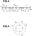
- Figure 4 is a cross sectional diagram that illustrates a portion of the filter bed taken along line 3b-3b in Figure 3 .
- the filter bed 4 is constituted by four stainless steel plate shaped portions, for example.
- the filter bed 4 is constituted by a pair of half moon shaped portions 4a and 4b, and a substantially rectangular portion 4c which is provided between the half moon shaped portions 4a and 4b.
- One side of the rectangular portion 4c is formed as an arcuate shaped portion 47. Note that in Figure 3 , only halves of the portions 4a, 4b, and 4c are illustrated.
- the filter bed 4 is of a discoid shape which is linearly symmetrical at both sides of a diameter in Figure 3 .
- the filter bed 4 need not necessarily be constituted by portions which are divided in the same manner as that of the portions 4a, 4b, and 4c, and may be constituted by portions which are divided in different manners according to the size of the filtration tank 2.
- a great number of apertures 60 are formed through the filter bed 4, and the aforementioned strainers 12 are provided within these apertures 60.
- a plurality of small apertures 62 for threaded fastening are formed through the outer peripheries of each of the portions 4a, 4b, and 4c.
- an annular mounting ring 64 is formed on the inner peripheral surface of the filtration tank 2 along the inner periphery thereof. Screw apertures 63 that correspond to the small apertures 62 are formed in the mounting ring 64.
- support beams 66 which have T shaped cross sections are attached to the filtration tank 2 along the mutual joints of the portions 4a, 4b, and 4c. Screw apertures 63 are also formed in the support beam 66.
- the portions 4a, 4b, and 4c are fastened and fixed to the mounting ring 64 and the support beam 66 by screwing bolts 61 into the small apertures 62 and the screw apertures 63.
- a support beam 67 which has a T shaped cross section is provided substantially at the center of the filtration tank 2 orthogonal to the support beams 66 and coupled to the support beams 66.
- the support beam 67 has screw apertures 63, and the portion 4c is fastened and fixed to the support beam 67 by screwing a bolt 61 into the screw apertures 63 and the small apertures 62 in the same manner as that described above.
- support beams 68 are provided on the left and right sides of the support beam 67.
- the support beams 68 are provided simply to receive the load of the portions 4a and 4b, and the portions 4a, 4b and 4c are fixed to the support beam 68 by threaded fastening or the like.
- the strainers 12 which are provided in the filter floor 4 will be described.
- the strainers 12 are commercially available "AB strainers” which are pipes with hollow umbrella portions 18 at the leading ends thereof, for example, and are formed by ABS resin or PP (polypropylene).
- ABS resin or PP polypropylene
- a plurality of concentric narrow slots 19 (liquid passage portions) that the filtration media 14 cannot pass through are formed in the umbrella portions 18, such that only filtered liquid pass through the filter bed 4 in the downward direction.
- the slots 19 of the center strainer 12 are illustrated.
- Male screws are formed on the pipe portions of the strainers 12.
- Nuts 65 threadedly engage the male screws to mount the strainers 12 to the filter bed 4 by the nuts 65 and the umbrella portions 18.
- the slots 19 may be of a size that the filtration media 14 cannot pass through, and the width thereof is set to be generally within a range from about 0.1 mm to 2.0 mm.
- the strainers 12 are not limited to the aforementioned type having the aforementioned umbrella portion, but may be other conventionally known strainers having pillar shaped portions or semicircular portions.
- the raw water 16 is injected into the filtration tank 2 through the raw water injection pipe 56. At this time, air within the filtration tank 2 is discharged through the air vent valve 81.
- the water level of the raw water 16 is set so as to reach the upper portion of the filtration tank 2 beyond the raw water injection pipe 56, that is, substantially the entire interior of the filtration tank 2 is filled with the raw water 16.
- the raw water 16 permeates the filtration media 14 at the exterior of the cleansing tank 38, and also enters the cleansing tank 38 through the upper opening 42. Therefore, the raw water 16 permeates the filtration media 14 in the cleansing tank 38 and is also filtered within the cleansing tank 38.
- the water which has permeated through the filtration media 14 and has been filtered passes through the filter bed 4 via the strainers 12, is sent out to the exterior through the processed water outlet pipe 46 at the lower portion of the filtration tank 2, and is supplied for utilization.
- the filter bed 4 and the strainers 12 constitute a water collecting mechanism.
- the backflow of the backwash water described above is continued during the initial stage of rotation of the screw 32.
- the load on the motor 26 during screw rotation is reduced, and mixing and movement of the filtration media 14 at the exterior of the cleansing tank 38 and the filtration media 14 within the interior of the cleansing tank 38 are facilitated the centrifugal force of the screw 32.
- the entirety of the filtration medium 14 is evenly cleansed.
- the supply of backwash water is subsequently reduced in the amount which is supplied (that is, the flow rate) or ceased.
- the rotation of the screw 32 is continued to cleanse the filtration media 14.
- the particles of the filtration media 14 are conveyed upward by the rotation of the blade member 43 while rubbing against and scrubbing each other, and are discharged from the upper openings 42 to the exterior of the cleansing tank 38. Separation of contaminants from the filtration media 14 is promoted by the impact of the filtration media 14 with the surface of the water.
- the filtration media 14 which has dropped back into the water is conveyed upwards into the cleansing tank 38 repeatedly, and scrubbed therein. In this manner, contaminants are separated from the filtration media 14 by repetitive cleansing within the cleansing tank 38.
- the lower end of the screw conveyor 32 is positioned in the vicinity of the filter bed 4. Therefore, the filtration media 14 in the vicinity of the filter bed 4 is conveyed upward as well, thereby thoroughly cleansing the entirety of the filtration media 14.
- the purified water is backwashed again from the processed water discharge pipe 46 prior to the rotation of the screw being ceased, to conduct backwash cleansing (backwashing) that imparts a rinsing effect.
- backwash cleansing backwashing
- This backwashing is continued after the screw conveyor 32 ceases to rotate.
- the backwashed water which is backwashed from the processed water discharge pipe 46, sprays into the layer of filtration media 14 through the slots 19 of the strainers 12 within the filter bed 4. Contaminants, which are trapped in the strainers 12, are also easily removed through the slots 19 by the backwashed water.
- the contaminants, which are separated from the filtration media 14, float and are expelled to the exterior through the raw water injection pipe 56 along with water that contains contaminants.
- the backwashed water cleaning water
- the backwashed water is also effectively backwashed through the interior of the cleansing tank 38 during the backwash cleansing, by passing through the aforementioned gap of the blade member 43. Therefore, contaminants within the cleansing tank 38 are also expelled as well.
- the spiral blade member 43 is formed by a metal such as stainless steel, for example.
- the blade member 43 is of a shape as illustrated in Figure 5 when viewed in the direction of the long axis of the screw 32. That is, the blade member 43 is present in an annular manner about the periphery of a central aperture 43 a, at which no member is present. Thereby, the screw 32 is in the shape of a coil spring across substantially the entire length thereof.
- each of the reinforcing members 35 is in the shape of an elongated plate, which is cut out from a cylindrical member along the long axis thereof.
- These reinforcing members 35 are fixed to the inner peripheral edge (on the inner peripheral surface in the present example) of the annular blade member 43 by welding or the like, and couple the portions of the blade member 43 which are separated from each other by welding or the like.
- each of the four reinforcing members 35 is fixed to one of the surfaces (the lower surface) of the disk 37 by welding or the like.
- the blade member 43 is also fixed to the disk 37, by one end surface (the upper end surface) of the screw 32 being welded to one of the surfaces of the disk 37.
- the motor 26 rotates the drive shaft 34 and rotates the disk 37, thereby rotating the blade member 43.
- the cleansing of the filtration media 14 by the cleansing mechanism 6 as described above is conducted by rotating the blade member 43 in this manner.
- a common screw which is conventionally employed in this type of filtration apparatus is that in which a blade member is mounted about a rotational axis that extends through a central portion.
- the screw 32 of the present embodiment is that which is in the shape of a coil spring, as described above. It is difficult for the screw 32 having the shape of the coil spring in this manner to secure a sufficient strength in the case that it is basically constituted only by the blade member 43.
- the screw 32 according to the present embodiment is reinforced by the four reinforcing members 35 described above, and is that which is equipped with a sufficient amount of strength.
- the circular aperture 43a is present at the center of the screw 32. Therefore, the filtration media 14 which are present within the portion of the circular aperture 43a are also effectively utilized for filtration. In this manner, the filtration apparatus of the present invention is capable of securing a greater filtration area compared to conventional apparatuses having filtration tanks with the same cross sectional area. As a result, it becomes possible to improve filtration efficiency.
- the filter media cleansing efficiency is improved.
- the circular aperture 43a is provided at the center of the screw 32, the flow of backwash water into the cleansing tank 38 is facilitated, the backwash cleansing effect is enhanced, and the filtration media cleansing efficiency is also improved.
- the shape of the screw 32 is that which has the circular aperture 43a in the center thereof. Therefore, it is possible for the weight of the screw 32 to be reduced. If the weight of the screw 32 is reduced in this manner, a member having a relatively low strength may be applied as a member such as a mirror plate that constitutes the bottom wall 9 and the upper wall 20. Thereby, a reduction in cost of the filtration apparatus 1 can also be realized.
Description
- The present invention is related to a filtration apparatus, more specifically, a filtration apparatus which has a filtration media layer within a filtration tank that filters supplied raw water through the filtration media layer, and particularly to a filtration apparatus that cleans filtration media with a screw provided within the filtration tank.
- Conventionally, filtration apparatuses that have a filtration media layer within a filtration tank that filter supplied raw water through the filtration media layer are known, as disclosed in
Patent Literature Patent Documents - The aforementioned cleansing mechanism that employs the screw is basically a mechanism which has a cylindrical outer cylinder arranged vertically in the filtration tank, a spiral screw provided along a drive shaft arranged in the outer cylinder, the screw, and a screw driving means for rotating the screw. The filtration media within the filtration tank is scrubbed and cleansed while being transferred upward by the screw.
- By cleansing the filter medium employing the screw cleansing mechanism described above, it is possible to eliminate a decrease in filtration efficiency due to clogging of the filtration media layer and contamination of the filtration media by adhered foreign matter and agglomerates.
-
- [Patent Literature 1]
Japanese Unexamined Patent Publication No. 2004-121885 - [Patent Literature 2]
Japanese Unexamined Patent Publication No. 2005-131443 - As described above, the filtration apparatus equipped with the screw cleansing mechanism can obtain a high filtration material cleansing effect, but there is still room for improvement in terms of filtration efficiency, filtration media cleansing efficiency, and weight reduction.
- The present invention has been developed in view of the foregoing circumstances. It is an object of the present invention to improve the filtration efficiency and the filtration media cleansing efficiency in a filtration apparatus provided with a screw cleansing mechanism, and to realize weight reduction.
- A filtration apparatus according to the present invention comprises a filtration tank;
- a layer of filtration media that filters supplied raw water by passing the raw water therethrough within the interior of the filtration tank; and
- a screw cleansing mechanism having a cylindrical outer cylinder which is provided within the filtration tank in a vertical orientation, a spiral shaped screw which is provided such that the long axis thereof extends in the longitudinal direction of the outer cylinder, and a screw driving means for rotating the screw, that scrubs and cleans filtration media by rotating the screw;
- characterized in that the shape of the screw as viewed from the direction of an axis of the screw is in a shape in which screw blade members are present in an annular manner around a central aperture at which no member is present.
- Such a coil spring shape is desirably applied over the entire length of the screw. However, a portion thereof, for example, an end portion in the direction of the long axis of the screw, may not be of such a shape.
- Note that in the filtration apparatus of the present invention, it is desirable for a drive shaft of the drive means to be coupled to screw blade members that constitute the screw at one end in the direction of the long axis of the screw.
- In addition, in the filtration apparatus of the present invention, it is desirable for a reinforcing member that extends in direction of the long axis of the screw through practically the entire length of the screw and that couples portions of the screw blade members which are spaced apart to be fixed to the inner peripheral portion of the screw blade members that constitute the screw.
- In the case that the drive shaft of the drive means is coupled to the one end of the screw blade member in the direction of the long axis of the screw as described above, it is desirable for the reinforcing member to be coupled to the drive shaft of the drive means either directly or via a coupling member that functions to couple the drive shaft to the one end of the screw blade member.
- In the filtration apparatus of the present invention, the screw is in the shape of a coil spring. That is, the shape of the screw as viewed from the direction of the long axis of the screw is a shape in which the screw blade members are present in an annular manner around the central aperture at which no member is present. Therefore, filtration media which are present in the portion of the aperture may be effectively utilized for filtration. In this manner, the filtration apparatus of the present invention is capable of securing a greater filtration area compared to conventional apparatuses having filtration tanks with the same cross sectional area. As a result, it becomes possible to improve filtration efficiency.
- In addition, during cleansing of the filtration media, the filtration media which are present in the central aperture of the screw is stirred and mixed by the vortex generated by the rotation of the screw, and from this point, the filter media cleansing efficiency is improved. Further, also during backwash cleansing, because the aperture is provided at the center of the screw, the flow of backwash water into the outer cylinder is facilitated, the backwash cleansing effect is enhanced, and the filtration media cleansing efficiency is also improved.
- Further, the shape of the screw is that which has an aperture in the center in the filtration apparatus of the present invention. Therefore, it is possible for the weight of the screw to be reduced. If the weight of the screw is reduced in this manner, a member having a relatively low strength may be applied as a member such as a mirror plate that constitutes the filtration tank. Thereby, a reduction in cost of the filtration apparatus can also be realized.
-
- [
Figure 1 ] A cross sectional diagram that illustrates a filtration apparatus according to an embodiment of the present invention - [
Figure 2 ] A plan view that illustrates a filtration tank of the filtration apparatus ofFigure 1 - [
Figure 3 ] A plan view that illustrates a filter bed of the filtration apparatus ofFigure 1 - [
Figure 4 ] A cross sectional diagram that illustrates a portion of the filter bed taken alongline 3b-3b inFigure 3 - [
Figure 5 ] A partial plan diagram that illustrates a screw of the filtration apparatus ofFigure 1 - Hereinafter, an embodiment of the filtration apparatus of the present invention will be described in detail with reference to the attached drawings.
Figure 1 is a cross sectional diagram that illustrates a filtration apparatus according to the embodiment of the present invention.Figure 2 is a plan view that illustrates a filter bed of the filtration tank ofFigure 1 . A description will be given with reference toFigure 1 andFigure 2 . - The
filtration apparatus 1 of the present embodiment has a substantiallycylindrical filtration tank 2 with a closed top and a closed bottom, a horizontally orientedfilter bed 4 provided within thefiltration tank 2 at the lower portion thereof and formed by a steel plate, for example, and a screw cleansing mechanism 6 (hereinafter, also referred to simply as "cleansing mechanism") which is mounted to a curvedupper wall 20 of thefiltration tank 2. Thecleansing mechanism 6 includes amotor 26, areduction gear mechanism 27, abase 28, a cleansing tank 38 (outer cylinder), and ascrew 32 to be described later. Further, thefiltration apparatus 1 has a processedwater outlet pipe 46 and a rawwater injection pipe 56. - Four support legs 8 (only one is illustrated in
Figure 1 ) are mounted on thefiltration tank 2. Thesupport legs 8 install thefiltration tank 2 on afloor surface 10. The configuration for supporting thefiltration tank 2 is not limited tosuch support legs 8, and a support structure or the like formed by winding a strip shaped plate material may be employed. Thefilter bed 4 is provided so as to be separated from acurved bottom wall 9 of thefiltration tank 2 in the upward direction. Thebottom wall 9 and the aforementionedupper wall 20 are formed by mirror plates, for example. A plurality ofstrainers 12 are installed on thefilter bed 4 to collect processed water (filtered water) and to pass it downward. The details of thefilter bed 4 and thestrainers 12 will be described later. Further, the aforementioned rawwater injection pipe 56 is located at the right side of thefiltration tank 2 inFigure 1 , and the outlet of the raw water is of a substantially upwardly oriented L shape. It is possible for the rawwater injection pipe 56 to be of other shapes. - A layer of a
filtration media 14 for filtering raw water which is injected from the rawwater injection pipe 56 is provided on thefilter bed 4. Thefilter bed 4 which is constituted by a steel plate, such as a stainless steel plate, for example, is generally formed to have a thickness within a range from about 5 mm to about 30 mm, in order to support the weight of thefiltration media 14, etc. Specifically, thefiltration media 14 have a diameter (particle size) within a range from about 0.2 mm to about 4.9 mm. This diameter depends on the quality of the raw water to be treated, but is generally more preferably within a range from about 0.6 to about 1 mm. A plurality of types offiltration media 14 may be stacked. In this case, as an example, sand having a diameter of about 0.6 mm on the lower side, anthracite having a diameter of about 1.2 mm on the upper side, etc. may be employed. The details of thefilter bed 4 will be described later.Raw water 16 which flows in from above thefiltration media 14 passes through the layer of thefiltration media 14, is filtered, passes through thestrainer 12, and flows downward from thefilter bed 4 as purified processed water. - A circular mounting
opening 22 is formed in the central portion of theupper wall 20 of the filtration tank2. Thecleansing mechanism 6 is mounted in the mountingopening 22 by bolts (not shown). The peripheral edge of the mountingopening 22 is formed to be a mountingrim 24. Thebase 28, on which themotor 26 and thereduction gear mechanism 27 are mounted, is mounted on therim 24. A holdingunit 36 which has a plurality ofbearings 30 is formed on thebase 28. Thebearings 30 support adrive shaft 34 for rotating the screw to be described later in a rotatable manner without shifting. - Next, the
cleansing mechanism 6 will be described in detail. The cylindrical cleansing tank 38 (outer cylinder) of thecleansing mechanism 6 has a disk shaped mountingwall 29 at the upper portion thereof. The mountingwall 29 is mounted to therim 24 together with the base 28 by bolts (not shown). In the drawings, the bolts are substituted by center lines that indicate the positions thereof. When the upper portion of thecleansing tank 38 is mounted to therim 24 in this manner, substantially theentire cleansing tank 38 is in a state in which it is suspended from the upper portion of thefiltration tank 2. - As illustrated in
Figure 1 , the lower portion of thecleansing tank 38 is a circularlower opening 40. A plurality ofupper openings 42 that extend in the vertical direction are formed at predetermined intervals at the upper portion of thecleansing tank 38 along the outer circumference. The positional relationship between the cleansingtank 38 and thefiltration media 14 is determined such that thelower opening 40 is located within thefiltration media 14. Ascrew 32 that constitutes a screw conveyor together with thecleansing tank 38 is provided within thecleansing tank 38. Thedrive shaft 34 for rotating thescrew 32 is constituted by of a reduceddiameter portion 34a having a relatively small diameter and alarge diameter portion 34b having a large diameter. - The
drive shaft 34 is connected to themotor 26 via a joint 49. Thelarge diameter portion 34b for imparting strength to thedrive shaft 34 has a portion having a predetermined length and is of a solid rod shape below an upper end portion, and adisk 37 which is fixed to the lower end portion thereof. A spiral screw blade member 43 (hereinafter, simply referred to as "blade member") is coupled to thedisk 37. Therefore, when thedrive shaft 34 of themotor 26 is rotated, theblade member 43 is rotated. The coupling between theblade member 43 and thedisk 37 will be described in detail later. - The
blade member 43 is provided such that there is a slight gap between the outer edge thereof and the inner peripheral surface of thecleansing tank 38. The dimension of this gap is desirably about three times the particle size of thefiltration media 14. This gap reduces the possibility that thefiltration media 14 will be crushed even if thefiltration media 14 becomes caught between theblade member 43 and thecleansing tank 38. - Next, components which are attached to the outside of the
filtration tank 2 will be described. A processedwater outlet pipe 46 that extends downward is attached to the center of thecurved bottom wall 9 of thefiltration tank 2. The processed water which has passed through the layer of thefilter media 14 and then passed through thestrainer 12 as described above is discharged out of thefiltration tank 2 through the processedwater outlet pipe 46. Further, anair vent valve 81 for discharging air from within thefiltration tank 2 is attached to the upper portion of thefiltration tank 2. - Next, the
filter bed 4 will be described with reference toFigure 3 andFigure 4 .Figure 3 is a plan view that illustrates half of thefilter bed 4. In addition,Figure 4 is a cross sectional diagram that illustrates a portion of the filter bed taken alongline 3b-3b inFigure 3 . Thefilter bed 4 is constituted by four stainless steel plate shaped portions, for example. In greater detail, thefilter bed 4 is constituted by a pair of half moon shapedportions rectangular portion 4c which is provided between the half moon shapedportions rectangular portion 4c is formed as an arcuate shapedportion 47. Note that inFigure 3 , only halves of theportions filter bed 4 is of a discoid shape which is linearly symmetrical at both sides of a diameter inFigure 3 . Note that thefilter bed 4 need not necessarily be constituted by portions which are divided in the same manner as that of theportions filtration tank 2. - A great number of
apertures 60 are formed through thefilter bed 4, and theaforementioned strainers 12 are provided within theseapertures 60. In addition, a plurality ofsmall apertures 62 for threaded fastening are formed through the outer peripheries of each of theportions annular mounting ring 64 is formed on the inner peripheral surface of thefiltration tank 2 along the inner periphery thereof.Screw apertures 63 that correspond to thesmall apertures 62 are formed in the mountingring 64. In addition, support beams 66 which have T shaped cross sections are attached to thefiltration tank 2 along the mutual joints of theportions Screw apertures 63 are also formed in thesupport beam 66. Theportions ring 64 and thesupport beam 66 by screwingbolts 61 into thesmall apertures 62 and thescrew apertures 63. - In addition, a
support beam 67 which has a T shaped cross section is provided substantially at the center of thefiltration tank 2 orthogonal to the support beams 66 and coupled to the support beams 66. Thesupport beam 67 hasscrew apertures 63, and theportion 4c is fastened and fixed to thesupport beam 67 by screwing abolt 61 into thescrew apertures 63 and thesmall apertures 62 in the same manner as that described above. Further, as illustrated inFigure 4 , support beams 68 are provided on the left and right sides of thesupport beam 67. The support beams 68 are provided simply to receive the load of theportions portions support beam 68 by threaded fastening or the like. - Next, the
strainers 12 which are provided in thefilter floor 4 will be described. Thestrainers 12 are commercially available "AB strainers" which are pipes withhollow umbrella portions 18 at the leading ends thereof, for example, and are formed by ABS resin or PP (polypropylene). A plurality of concentric narrow slots 19 (liquid passage portions) that thefiltration media 14 cannot pass through are formed in theumbrella portions 18, such that only filtered liquid pass through thefilter bed 4 in the downward direction. - Note that in
Figure 4 , only theslots 19 of thecenter strainer 12 are illustrated. Male screws are formed on the pipe portions of thestrainers 12.Nuts 65 threadedly engage the male screws to mount thestrainers 12 to thefilter bed 4 by the nuts 65 and theumbrella portions 18. Theslots 19 may be of a size that thefiltration media 14 cannot pass through, and the width thereof is set to be generally within a range from about 0.1 mm to 2.0 mm. In addition, thestrainers 12 are not limited to the aforementioned type having the aforementioned umbrella portion, but may be other conventionally known strainers having pillar shaped portions or semicircular portions. - Next, filtering by the
filtration tank 2 will be described, with reference toFigure 1 again. First, theraw water 16 is injected into thefiltration tank 2 through the rawwater injection pipe 56. At this time, air within thefiltration tank 2 is discharged through theair vent valve 81. In the case of the present embodiment, the water level of theraw water 16 is set so as to reach the upper portion of thefiltration tank 2 beyond the rawwater injection pipe 56, that is, substantially the entire interior of thefiltration tank 2 is filled with theraw water 16. Theraw water 16 permeates thefiltration media 14 at the exterior of thecleansing tank 38, and also enters thecleansing tank 38 through theupper opening 42. Therefore, theraw water 16 permeates thefiltration media 14 in thecleansing tank 38 and is also filtered within thecleansing tank 38. - The water which has permeated through the
filtration media 14 and has been filtered (processed water) passes through thefilter bed 4 via thestrainers 12, is sent out to the exterior through the processedwater outlet pipe 46 at the lower portion of thefiltration tank 2, and is supplied for utilization. Note that thefilter bed 4 and thestrainers 12 constitute a water collecting mechanism. - Next, methods for cleansing the
filtration media 14 in order to resolve clogging within the layer of thefiltration media 14 will be described in detail. Note that there are two types of filtration media cleansing methods which are conducted by the present apparatus. The first is that in which thescrew 32 is rotated while backwash water is being supplied, and the second is that in which only the backwash water is suppled. Hereinafter, the former will be simply referred to as "cleansing" or "screw cleansing", and the latter will be referred to as "backwash cleansing" or "backwashing". - First, screw cleansing will be described. Prior to the
motor 26 for rotating thescrew 32 being started, purified water (backwash water) is caused to flow back into thefiltration tank 2 from the processedwater outlet pipe 46, and purified water is ejected into thefiltration medium 14 through thefilter bed 4. When the backwash water is sprayed onto thefiltration media 14 from below, thefiltration media 14 floats in the backwash water (if raw water is remaining, in the backwash water and the raw water). As a result, the load on themotor 26 when the motor is started is reduced. When themotor 26 is driven and thescrew 32 rotates, thefiltration media 14 is pushed up into theupper cleansing tank 38 by theblade member 43 of thescrew 32, particularly theblade member 43 of the portion exposed below thecleansing tank 38. - The backflow of the backwash water described above is continued during the initial stage of rotation of the
screw 32. By rotating thescrew 32 in the same state as under backflow cleansing in this manner, the load on themotor 26 during screw rotation is reduced, and mixing and movement of thefiltration media 14 at the exterior of thecleansing tank 38 and thefiltration media 14 within the interior of thecleansing tank 38 are facilitated the centrifugal force of thescrew 32. As a result, the entirety of thefiltration medium 14 is evenly cleansed. The supply of backwash water is subsequently reduced in the amount which is supplied (that is, the flow rate) or ceased. However, the rotation of thescrew 32 is continued to cleanse thefiltration media 14. - The particles of the
filtration media 14 are conveyed upward by the rotation of theblade member 43 while rubbing against and scrubbing each other, and are discharged from theupper openings 42 to the exterior of thecleansing tank 38. Separation of contaminants from thefiltration media 14 is promoted by the impact of thefiltration media 14 with the surface of the water. Thefiltration media 14 which has dropped back into the water is conveyed upwards into thecleansing tank 38 repeatedly, and scrubbed therein. In this manner, contaminants are separated from thefiltration media 14 by repetitive cleansing within thecleansing tank 38. As described above and as illustrated inFigure 1 , the lower end of thescrew conveyor 32 is positioned in the vicinity of thefilter bed 4. Therefore, thefiltration media 14 in the vicinity of thefilter bed 4 is conveyed upward as well, thereby thoroughly cleansing the entirety of thefiltration media 14. - Note that during the filtration medial cleansing process which is conducted by the
screw cleansing mechanism 6, supply of the purified water that causes thefiltration media 14 to float is repeated a plurality of times while thescrew 32 is rotated continuously with the periods during which the amount of supply is reduced and the periods during which the supply is ceased as intervals therebetween. - When the filtration medial cleansing process which is conducted by the
screw cleansing mechanism 6 is complete, the purified water is backwashed again from the processedwater discharge pipe 46 prior to the rotation of the screw being ceased, to conduct backwash cleansing (backwashing) that imparts a rinsing effect. This backwashing is continued after thescrew conveyor 32 ceases to rotate. The backwashed water, which is backwashed from the processedwater discharge pipe 46, sprays into the layer offiltration media 14 through theslots 19 of thestrainers 12 within thefilter bed 4. Contaminants, which are trapped in thestrainers 12, are also easily removed through theslots 19 by the backwashed water. - The contaminants, which are separated from the
filtration media 14, float and are expelled to the exterior through the rawwater injection pipe 56 along with water that contains contaminants. The backwashed water (cleansing water) is also effectively backwashed through the interior of thecleansing tank 38 during the backwash cleansing, by passing through the aforementioned gap of theblade member 43. Therefore, contaminants within thecleansing tank 38 are also expelled as well. - Next, the coupling between the
disk 37 and theblade member 43 illustrated inFigure 1 will be described in detail. Thespiral blade member 43 is formed by a metal such as stainless steel, for example. Theblade member 43 is of a shape as illustrated inFigure 5 when viewed in the direction of the long axis of thescrew 32. That is, theblade member 43 is present in an annular manner about the periphery of acentral aperture 43 a, at which no member is present. Thereby, thescrew 32 is in the shape of a coil spring across substantially the entire length thereof. - In addition, four long reinforcing
members 35 that extend in the direction of the long axis of theblade member 43, for example, are fixed to the inner peripheral portion of theannular blade member 43 across substantially the entire length thereof. These reinforcingmembers 35 are also formed by a metal such as stainless steel, for example. In greater detail, each of the reinforcingmembers 35 is in the shape of an elongated plate, which is cut out from a cylindrical member along the long axis thereof. These reinforcingmembers 35 are fixed to the inner peripheral edge (on the inner peripheral surface in the present example) of theannular blade member 43 by welding or the like, and couple the portions of theblade member 43 which are separated from each other by welding or the like. - One end of each of the four reinforcing
members 35 is fixed to one of the surfaces (the lower surface) of thedisk 37 by welding or the like. In addition, theblade member 43 is also fixed to thedisk 37, by one end surface (the upper end surface) of thescrew 32 being welded to one of the surfaces of thedisk 37. In the configuration described above, themotor 26 rotates thedrive shaft 34 and rotates thedisk 37, thereby rotating theblade member 43. The cleansing of thefiltration media 14 by thecleansing mechanism 6 as described above is conducted by rotating theblade member 43 in this manner. - A common screw which is conventionally employed in this type of filtration apparatus is that in which a blade member is mounted about a rotational axis that extends through a central portion. In contrast, the
screw 32 of the present embodiment is that which is in the shape of a coil spring, as described above. It is difficult for thescrew 32 having the shape of the coil spring in this manner to secure a sufficient strength in the case that it is basically constituted only by theblade member 43. However, thescrew 32 according to the present embodiment is reinforced by the four reinforcingmembers 35 described above, and is that which is equipped with a sufficient amount of strength. - As described above, in the
filtration apparatus 1 of the present embodiment, thecircular aperture 43a is present at the center of thescrew 32. Therefore, thefiltration media 14 which are present within the portion of thecircular aperture 43a are also effectively utilized for filtration. In this manner, the filtration apparatus of the present invention is capable of securing a greater filtration area compared to conventional apparatuses having filtration tanks with the same cross sectional area. As a result, it becomes possible to improve filtration efficiency. - In addition, during cleansing of the
filtration media 14, thefiltration media 14 which are present in the centralcircular aperture 43a of thescrew 32 is stirred and mixed by the vortex generated by the rotation of thescrew 32, and from this point, the filter media cleansing efficiency is improved. Further, also during backwash cleansing, because thecircular aperture 43a is provided at the center of thescrew 32, the flow of backwash water into thecleansing tank 38 is facilitated, the backwash cleansing effect is enhanced, and the filtration media cleansing efficiency is also improved. - Further, in the
filtration apparatus 1 of the embodiment, the shape of thescrew 32 is that which has thecircular aperture 43a in the center thereof. Therefore, it is possible for the weight of thescrew 32 to be reduced. If the weight of thescrew 32 is reduced in this manner, a member having a relatively low strength may be applied as a member such as a mirror plate that constitutes thebottom wall 9 and theupper wall 20. Thereby, a reduction in cost of thefiltration apparatus 1 can also be realized. -
- 1
- filtration apparatus
- 2
- filtration tank
- 4
- filter bed
- 6
- screw cleansing mechanism
- 12
- strainer
- 14
- filtration media
- 16
- raw water
- 26
- motor
- 32
- screw
- 34
- drive shaft
- 35
- reinforcing member
- 37
- disk
- 38
- cleansing tank (outer cylinder)
- 43
- screw blade member
Claims (3)
- A filtration apparatus (1) comprising:a filtration tank (2);a layer of filtration media (14) that filters supplied raw water (16) by passing the raw water (16) therethrough within the interior of the filtration tank (2); anda screw cleansing mechanism (6) having a cylindrical outer cylinder (38) which is provided within the filtration tank (2) in a vertical orientation, a spiral shaped screw (32) which is provided such that the long axis thereof extends in the longitudinal direction of the outer cylinder (38), and a screw driving means for rotating the screw, that scrubs and cleans filtration media (14) by rotating the screw;characterized in that the shape of the screw (32) as viewed from the direction of an axis of the screw (32) is in a shape in which screw blade members (43) are present in an annular manner around a central aperture (43a) at which no member is present.
- The filtration apparatus (1) of Claim 1, wherein:
a drive shaft of the screw driving means is coupled to the screw blade members (43) that constitute the screw (32) at one end in the direction of the axis of the screw (32). - The filtration apparatus (1) of either one of Claim 1 and Claim 2, wherein:
a reinforcing member (35) that extends in direction of the long axis of the screw (32) through practically the entire length of the screw (32) and that couples portions of the screw blade members (43) which are spaced apart is fixed to the inner peripheral portion of the screw blade members (43) that constitute the screw (32).
Applications Claiming Priority (2)
| Application Number | Priority Date | Filing Date | Title |
|---|---|---|---|
| JP2018093047A JP7129208B2 (en) | 2018-05-14 | 2018-05-14 | filtration device |
| PCT/JP2019/018882 WO2019221048A1 (en) | 2018-05-14 | 2019-05-13 | Filtration device |
Publications (3)
| Publication Number | Publication Date |
|---|---|
| EP3795228A1 EP3795228A1 (en) | 2021-03-24 |
| EP3795228A4 EP3795228A4 (en) | 2022-02-09 |
| EP3795228B1 true EP3795228B1 (en) | 2023-07-05 |
Family
ID=68540262
Family Applications (1)
| Application Number | Title | Priority Date | Filing Date |
|---|---|---|---|
| EP19802637.9A Active EP3795228B1 (en) | 2018-05-14 | 2019-05-13 | Filtration device |
Country Status (7)
| Country | Link |
|---|---|
| US (1) | US11173429B2 (en) |
| EP (1) | EP3795228B1 (en) |
| JP (1) | JP7129208B2 (en) |
| KR (1) | KR20210009324A (en) |
| CN (1) | CN112105432A (en) |
| PL (1) | PL3795228T3 (en) |
| WO (1) | WO2019221048A1 (en) |
Families Citing this family (2)
| Publication number | Priority date | Publication date | Assignee | Title |
|---|---|---|---|---|
| CN113577902A (en) * | 2021-08-04 | 2021-11-02 | 湖南多灵过滤系统科技有限公司 | Filtration system based on shallow media filter |
| CN116376693A (en) * | 2023-05-23 | 2023-07-04 | 南京南大药业有限责任公司 | Low-residue low-molecular-weight heparin sodium production method and equipment |
Family Cites Families (13)
| Publication number | Priority date | Publication date | Assignee | Title |
|---|---|---|---|---|
| CN1213785C (en) | 2000-04-27 | 2005-08-10 | 日本原料株式会社 | Filtration device, and method of cleaning filter material container in filtration device |
| GB2380952B (en) * | 2001-10-22 | 2005-03-30 | Nihon Genryo Co Ltd | Filtration apparatus |
| JP3936569B2 (en) * | 2001-10-31 | 2007-06-27 | 三菱化工機株式会社 | Screw press |
| JP3919098B2 (en) | 2001-11-19 | 2007-05-23 | 日本原料株式会社 | Filtration device |
| JP3959036B2 (en) | 2002-08-09 | 2007-08-15 | 日本原料株式会社 | Filtration device |
| JP2005131443A (en) * | 2003-10-28 | 2005-05-26 | Nippon Genryo Kk | Filtration apparatus |
| JP5190529B2 (en) * | 2006-04-21 | 2013-04-24 | 前澤工業株式会社 | Wastewater treatment equipment |
| JP5410656B2 (en) * | 2007-05-17 | 2014-02-05 | 日本原料株式会社 | External filter media cleaning device for filtration equipment |
| JP6386220B2 (en) * | 2013-10-10 | 2018-09-05 | 月島機械株式会社 | Vertical screw press filtration device |
| JP6055396B2 (en) * | 2013-11-25 | 2016-12-27 | 月島機械株式会社 | Vertical screw press filtration device |
| CN104607303A (en) * | 2015-01-20 | 2015-05-13 | 刘建国 | Concrete sandstone separator |
| JP2017018895A (en) * | 2015-07-10 | 2017-01-26 | 神奈川機器工業株式会社 | Filter element, back wash-type filtration apparatus, and filtration method and back washing method for filter element |
| CN206415212U (en) * | 2016-12-26 | 2017-08-18 | 深圳市深港产学研环保工程技术股份有限公司 | Sand material cleaning device with sorting function |
-
2018
- 2018-05-14 JP JP2018093047A patent/JP7129208B2/en active Active
-
2019
- 2019-05-13 CN CN201980031229.2A patent/CN112105432A/en active Pending
- 2019-05-13 US US17/054,688 patent/US11173429B2/en active Active
- 2019-05-13 PL PL19802637.9T patent/PL3795228T3/en unknown
- 2019-05-13 KR KR1020207034069A patent/KR20210009324A/en unknown
- 2019-05-13 WO PCT/JP2019/018882 patent/WO2019221048A1/en unknown
- 2019-05-13 EP EP19802637.9A patent/EP3795228B1/en active Active
Also Published As
| Publication number | Publication date |
|---|---|
| US11173429B2 (en) | 2021-11-16 |
| WO2019221048A1 (en) | 2019-11-21 |
| EP3795228A1 (en) | 2021-03-24 |
| JP2019198805A (en) | 2019-11-21 |
| JP7129208B2 (en) | 2022-09-01 |
| CN112105432A (en) | 2020-12-18 |
| US20210069617A1 (en) | 2021-03-11 |
| KR20210009324A (en) | 2021-01-26 |
| PL3795228T3 (en) | 2024-01-03 |
| EP3795228A4 (en) | 2022-02-09 |
Similar Documents
| Publication | Publication Date | Title |
|---|---|---|
| US7160452B2 (en) | Filter device | |
| KR102244809B1 (en) | Frame type disc filter with bypass control to prevent bypass water from being used for backwash | |
| EP3795228B1 (en) | Filtration device | |
| CA2465705C (en) | Filtration apparatus | |
| US5171443A (en) | Granular media regeneration apparatus | |
| RU2317841C2 (en) | Device for filtering food liquids, mainly milk | |
| US4102790A (en) | Filter underdrain | |
| EP1683561B1 (en) | Filtration device | |
| JP4537468B2 (en) | Rotary filtration device | |
| JP2013188689A (en) | Filter element and filtering device | |
| JP3239920B2 (en) | Combined filtration device | |
| EP0151127A1 (en) | A device for purification of liquid media such as waste water | |
| JP4044697B2 (en) | Liquid processing tower | |
| KR102489997B1 (en) | Filtration material washing machine | |
| WO2024084984A1 (en) | Filtering material cleaning device | |
| KR102137046B1 (en) | Filter Device | |
| JP2002166111A (en) | Solid-liquid separation apparatus | |
| JP2007144311A (en) | Apparatus for filtrating laundry waste liquid | |
| JPH09978A (en) | Strainer | |
| JPH09262412A (en) | Filter |
Legal Events
| Date | Code | Title | Description |
|---|---|---|---|
| STAA | Information on the status of an ep patent application or granted ep patent |
Free format text: STATUS: THE INTERNATIONAL PUBLICATION HAS BEEN MADE |
|
| STAA | Information on the status of an ep patent application or granted ep patent |
Free format text: STATUS: THE INTERNATIONAL PUBLICATION HAS BEEN MADE |
|
| PUAI | Public reference made under article 153(3) epc to a published international application that has entered the european phase |
Free format text: ORIGINAL CODE: 0009012 |
|
| STAA | Information on the status of an ep patent application or granted ep patent |
Free format text: STATUS: REQUEST FOR EXAMINATION WAS MADE |
|
| 17P | Request for examination filed |
Effective date: 20201111 |
|
| AK | Designated contracting states |
Kind code of ref document: A1 Designated state(s): AL AT BE BG CH CY CZ DE DK EE ES FI FR GB GR HR HU IE IS IT LI LT LU LV MC MK MT NL NO PL PT RO RS SE SI SK SM TR |
|
| AX | Request for extension of the european patent |
Extension state: BA ME |
|
| DAV | Request for validation of the european patent (deleted) | ||
| DAX | Request for extension of the european patent (deleted) | ||
| A4 | Supplementary search report drawn up and despatched |
Effective date: 20220112 |
|
| RIC1 | Information provided on ipc code assigned before grant |
Ipc: B01D 24/14 20060101ALI20220105BHEP Ipc: B01D 24/46 20060101ALI20220105BHEP Ipc: B01D 24/00 20060101ALI20220105BHEP Ipc: B01D 29/66 20060101AFI20220105BHEP |
|
| GRAP | Despatch of communication of intention to grant a patent |
Free format text: ORIGINAL CODE: EPIDOSNIGR1 |
|
| STAA | Information on the status of an ep patent application or granted ep patent |
Free format text: STATUS: GRANT OF PATENT IS INTENDED |
|
| RIC1 | Information provided on ipc code assigned before grant |
Ipc: B01D 24/14 19900101ALI20230105BHEP Ipc: B01D 24/46 19900101ALI20230105BHEP Ipc: B01D 24/00 19900101ALI20230105BHEP Ipc: B01D 29/66 19900101AFI20230105BHEP |
|
| INTG | Intention to grant announced |
Effective date: 20230207 |
|
| GRAS | Grant fee paid |
Free format text: ORIGINAL CODE: EPIDOSNIGR3 |
|
| GRAA | (expected) grant |
Free format text: ORIGINAL CODE: 0009210 |
|
| STAA | Information on the status of an ep patent application or granted ep patent |
Free format text: STATUS: THE PATENT HAS BEEN GRANTED |
|
| AK | Designated contracting states |
Kind code of ref document: B1 Designated state(s): AL AT BE BG CH CY CZ DE DK EE ES FI FR GB GR HR HU IE IS IT LI LT LU LV MC MK MT NL NO PL PT RO RS SE SI SK SM TR |
|
| REG | Reference to a national code |
Ref country code: CH Ref legal event code: EP |
|
| REG | Reference to a national code |
Ref country code: AT Ref legal event code: REF Ref document number: 1584300 Country of ref document: AT Kind code of ref document: T Effective date: 20230715 |
|
| P01 | Opt-out of the competence of the unified patent court (upc) registered |
Effective date: 20230613 |
|
| REG | Reference to a national code |
Ref country code: DE Ref legal event code: R096 Ref document number: 602019032249 Country of ref document: DE |
|
| REG | Reference to a national code |
Ref country code: IE Ref legal event code: FG4D |
|
| REG | Reference to a national code |
Ref country code: LT Ref legal event code: MG9D |
|
| REG | Reference to a national code |
Ref country code: NL Ref legal event code: MP Effective date: 20230705 |
|
| REG | Reference to a national code |
Ref country code: AT Ref legal event code: MK05 Ref document number: 1584300 Country of ref document: AT Kind code of ref document: T Effective date: 20230705 |
|
| PG25 | Lapsed in a contracting state [announced via postgrant information from national office to epo] |
Ref country code: NL Free format text: LAPSE BECAUSE OF FAILURE TO SUBMIT A TRANSLATION OF THE DESCRIPTION OR TO PAY THE FEE WITHIN THE PRESCRIBED TIME-LIMIT Effective date: 20230705 |
|
| PG25 | Lapsed in a contracting state [announced via postgrant information from national office to epo] |
Ref country code: GR Free format text: LAPSE BECAUSE OF FAILURE TO SUBMIT A TRANSLATION OF THE DESCRIPTION OR TO PAY THE FEE WITHIN THE PRESCRIBED TIME-LIMIT Effective date: 20231006 |
|
| PG25 | Lapsed in a contracting state [announced via postgrant information from national office to epo] |
Ref country code: ES Free format text: LAPSE BECAUSE OF FAILURE TO SUBMIT A TRANSLATION OF THE DESCRIPTION OR TO PAY THE FEE WITHIN THE PRESCRIBED TIME-LIMIT Effective date: 20230705 |
|
| PG25 | Lapsed in a contracting state [announced via postgrant information from national office to epo] |
Ref country code: IS Free format text: LAPSE BECAUSE OF FAILURE TO SUBMIT A TRANSLATION OF THE DESCRIPTION OR TO PAY THE FEE WITHIN THE PRESCRIBED TIME-LIMIT Effective date: 20231105 |
|
| PG25 | Lapsed in a contracting state [announced via postgrant information from national office to epo] |
Ref country code: SE Free format text: LAPSE BECAUSE OF FAILURE TO SUBMIT A TRANSLATION OF THE DESCRIPTION OR TO PAY THE FEE WITHIN THE PRESCRIBED TIME-LIMIT Effective date: 20230705 Ref country code: RS Free format text: LAPSE BECAUSE OF FAILURE TO SUBMIT A TRANSLATION OF THE DESCRIPTION OR TO PAY THE FEE WITHIN THE PRESCRIBED TIME-LIMIT Effective date: 20230705 Ref country code: PT Free format text: LAPSE BECAUSE OF FAILURE TO SUBMIT A TRANSLATION OF THE DESCRIPTION OR TO PAY THE FEE WITHIN THE PRESCRIBED TIME-LIMIT Effective date: 20231106 Ref country code: NO Free format text: LAPSE BECAUSE OF FAILURE TO SUBMIT A TRANSLATION OF THE DESCRIPTION OR TO PAY THE FEE WITHIN THE PRESCRIBED TIME-LIMIT Effective date: 20231005 Ref country code: LV Free format text: LAPSE BECAUSE OF FAILURE TO SUBMIT A TRANSLATION OF THE DESCRIPTION OR TO PAY THE FEE WITHIN THE PRESCRIBED TIME-LIMIT Effective date: 20230705 Ref country code: LT Free format text: LAPSE BECAUSE OF FAILURE TO SUBMIT A TRANSLATION OF THE DESCRIPTION OR TO PAY THE FEE WITHIN THE PRESCRIBED TIME-LIMIT Effective date: 20230705 Ref country code: IS Free format text: LAPSE BECAUSE OF FAILURE TO SUBMIT A TRANSLATION OF THE DESCRIPTION OR TO PAY THE FEE WITHIN THE PRESCRIBED TIME-LIMIT Effective date: 20231105 Ref country code: HR Free format text: LAPSE BECAUSE OF FAILURE TO SUBMIT A TRANSLATION OF THE DESCRIPTION OR TO PAY THE FEE WITHIN THE PRESCRIBED TIME-LIMIT Effective date: 20230705 Ref country code: GR Free format text: LAPSE BECAUSE OF FAILURE TO SUBMIT A TRANSLATION OF THE DESCRIPTION OR TO PAY THE FEE WITHIN THE PRESCRIBED TIME-LIMIT Effective date: 20231006 Ref country code: FI Free format text: LAPSE BECAUSE OF FAILURE TO SUBMIT A TRANSLATION OF THE DESCRIPTION OR TO PAY THE FEE WITHIN THE PRESCRIBED TIME-LIMIT Effective date: 20230705 Ref country code: ES Free format text: LAPSE BECAUSE OF FAILURE TO SUBMIT A TRANSLATION OF THE DESCRIPTION OR TO PAY THE FEE WITHIN THE PRESCRIBED TIME-LIMIT Effective date: 20230705 Ref country code: AT Free format text: LAPSE BECAUSE OF FAILURE TO SUBMIT A TRANSLATION OF THE DESCRIPTION OR TO PAY THE FEE WITHIN THE PRESCRIBED TIME-LIMIT Effective date: 20230705 |
|
| PG25 | Lapsed in a contracting state [announced via postgrant information from national office to epo] |
Ref country code: PL Free format text: LAPSE BECAUSE OF FAILURE TO SUBMIT A TRANSLATION OF THE DESCRIPTION OR TO PAY THE FEE WITHIN THE PRESCRIBED TIME-LIMIT Effective date: 20230705 |