EP3795222A1 - Glove, in particular goalkeeper glove - Google Patents
Glove, in particular goalkeeper glove Download PDFInfo
- Publication number
- EP3795222A1 EP3795222A1 EP20195895.6A EP20195895A EP3795222A1 EP 3795222 A1 EP3795222 A1 EP 3795222A1 EP 20195895 A EP20195895 A EP 20195895A EP 3795222 A1 EP3795222 A1 EP 3795222A1
- Authority
- EP
- European Patent Office
- Prior art keywords
- glove
- protrusions
- protrusion
- backside
- ball
- Prior art date
- Legal status (The legal status is an assumption and is not a legal conclusion. Google has not performed a legal analysis and makes no representation as to the accuracy of the status listed.)
- Granted
Links
Images



Classifications
-
- A—HUMAN NECESSITIES
- A63—SPORTS; GAMES; AMUSEMENTS
- A63B—APPARATUS FOR PHYSICAL TRAINING, GYMNASTICS, SWIMMING, CLIMBING, OR FENCING; BALL GAMES; TRAINING EQUIPMENT
- A63B71/00—Games or sports accessories not covered in groups A63B1/00 - A63B69/00
- A63B71/08—Body-protectors for players or sportsmen, i.e. body-protecting accessories affording protection of body parts against blows or collisions
- A63B71/14—Body-protectors for players or sportsmen, i.e. body-protecting accessories affording protection of body parts against blows or collisions for the hands, e.g. baseball, boxing or golfing gloves
- A63B71/141—Body-protectors for players or sportsmen, i.e. body-protecting accessories affording protection of body parts against blows or collisions for the hands, e.g. baseball, boxing or golfing gloves in the form of gloves
- A63B71/148—Gloves for bowling and other ball games
-
- A—HUMAN NECESSITIES
- A63—SPORTS; GAMES; AMUSEMENTS
- A63B—APPARATUS FOR PHYSICAL TRAINING, GYMNASTICS, SWIMMING, CLIMBING, OR FENCING; BALL GAMES; TRAINING EQUIPMENT
- A63B71/00—Games or sports accessories not covered in groups A63B1/00 - A63B69/00
- A63B71/08—Body-protectors for players or sportsmen, i.e. body-protecting accessories affording protection of body parts against blows or collisions
- A63B71/14—Body-protectors for players or sportsmen, i.e. body-protecting accessories affording protection of body parts against blows or collisions for the hands, e.g. baseball, boxing or golfing gloves
- A63B71/141—Body-protectors for players or sportsmen, i.e. body-protecting accessories affording protection of body parts against blows or collisions for the hands, e.g. baseball, boxing or golfing gloves in the form of gloves
-
- A—HUMAN NECESSITIES
- A41—WEARING APPAREL
- A41D—OUTERWEAR; PROTECTIVE GARMENTS; ACCESSORIES
- A41D19/00—Gloves
-
- A—HUMAN NECESSITIES
- A41—WEARING APPAREL
- A41D—OUTERWEAR; PROTECTIVE GARMENTS; ACCESSORIES
- A41D19/00—Gloves
- A41D19/0055—Plastic or rubber gloves
- A41D19/0058—Three-dimensional gloves
-
- A—HUMAN NECESSITIES
- A41—WEARING APPAREL
- A41D—OUTERWEAR; PROTECTIVE GARMENTS; ACCESSORIES
- A41D19/00—Gloves
- A41D19/015—Protective gloves
-
- A—HUMAN NECESSITIES
- A41—WEARING APPAREL
- A41D—OUTERWEAR; PROTECTIVE GARMENTS; ACCESSORIES
- A41D19/00—Gloves
- A41D19/015—Protective gloves
- A41D19/01505—Protective gloves resistant to mechanical aggressions, e.g. cutting. piercing
- A41D19/01517—Protective gloves resistant to mechanical aggressions, e.g. cutting. piercing with protection against crushing, e.g. of the finger tips
-
- A—HUMAN NECESSITIES
- A41—WEARING APPAREL
- A41D—OUTERWEAR; PROTECTIVE GARMENTS; ACCESSORIES
- A41D19/00—Gloves
- A41D19/015—Protective gloves
- A41D19/01523—Protective gloves absorbing shocks or vibrations
-
- A—HUMAN NECESSITIES
- A63—SPORTS; GAMES; AMUSEMENTS
- A63B—APPARATUS FOR PHYSICAL TRAINING, GYMNASTICS, SWIMMING, CLIMBING, OR FENCING; BALL GAMES; TRAINING EQUIPMENT
- A63B2209/00—Characteristics of used materials
-
- A—HUMAN NECESSITIES
- A63—SPORTS; GAMES; AMUSEMENTS
- A63B—APPARATUS FOR PHYSICAL TRAINING, GYMNASTICS, SWIMMING, CLIMBING, OR FENCING; BALL GAMES; TRAINING EQUIPMENT
- A63B2243/00—Specific ball sports not provided for in A63B2102/00 - A63B2102/38
- A63B2243/0025—Football
Definitions
- the present invention relates to a glove, in particular a goalkeeper glove.
- Gloves have been known for a long time in many different forms.
- gloves may serve to protect the hands from a number of environmental influences such as cold, heat or friction.
- gloves may protect the hands from injuries caused by chemical or physical impacts, such as blows or cuts.
- flexible elements are known from EP 2 901 875 B1 , which may be applied to gloves to protect the hand from the effects of pressure.
- the elements are each designed in the shape of a pyramid comprising a recess at the top such that the lateral surfaces of the pyramid-shaped element may fold inwards when the elements are subjected to pressure acting vertically on them.
- Gloves are used in numerous sports, both to protect the hands, such as in ice hockey, and to support and improve the hands in their functionality, such as in golf.
- KR 101345655 B1 discloses a golf glove with a number of holes which may improve the grip, but also the ventilation of the hand.
- US 8,082,601 B2 (whose application documents were published as US 2009/307820 A1 ) discloses a number of air-filled elements in the palm area of a glove, which may be of advantage when operating a club.
- the present invention is therefore based on the problem of providing a glove which increases the control of an object, in particular a ball, hitting the backside of the glove.
- a glove in particular a goalkeeper glove, comprises a plurality of protrusions, wherein the protrusions protrude from a backside of the glove and extend in a first direction away from the backside, and wherein the protrusions are adapted to deform in a second direction that comprises a component perpendicular to the first direction.
- This provides a glove that offers a significantly increased level of control when fisting away a ball.
- the ball may interact with this plurality of protrusions instead of with an often largely smooth surface, thereby increasing friction between the glove and the ball and consequently ball control.
- protrusions are adapted to deform in a second direction that comprises a component perpendicular to the first direction may further enhance this effect.
- this refers to deformability under forces such as those which usually occur in ball sports such as handball and/or soccer, in particular upon contact between a goalkeeper glove and a ball.
- protrusions according to the invention are preferably elastically or reversibly deformable, i.e. they resume their original shape as soon as no more force is applied to them.
- a deformation in the second direction thus refers to a deformation that acts at least partially perpendicular to the first direction in which the protrusions extend.
- the plurality of protrusions may be adapted to deform in the second direction upon contact of the backside of the glove with a ball such that a contact area of the glove with the ball is greater than without deformation of the plurality of protrusions.
- the protrusions may be deformed by the ball contact in such a way that they follow the sphericity of the ball, both as a whole and individually.
- the contact area may also be increased by multiple of the plurality of protrusions being tilted and/or sheared in the second direction.
- the ball does not only come into contact with end portions and/or upper parts of the protrusions. Rather, the lateral surfaces of the respective protrusions then also abut at least partially against the ball.
- the protrusions may thus virtually "hook" into the ball.
- At least one protrusion comprises a notch facilitating deformation. This may further enhance the described desirable effects caused by the general deformability of the protrusions. It may also allow to vary the stiffness and/or firmness of the respective protrusion in different directions. This may lead to the ball being deflected preferably in a certain direction.
- protrusions may take stiffer and/or firmer effect in selected directions than in others and thus help to deflect the ball preferably in a certain direction. In particular, this may also be used to cause at least one protrusion to be deformed against its tilted orientation upon contact of the backside of the glove with a ball. This results in a particularly high restoring force in the respective protrusion, which may lead to even greater friction between the glove and the ball and thus further improve ball control.
- a tilted orientation may be oriented towards the fingertips of the glove.
- a protrusion is oriented towards the fingertips of the glove in the sense of the invention even if it is only partially oriented towards the fingertips.
- a vector describing the orientation of the protrusion comprises a non-zero component for the direction pointing along the extension direction of the fingers.
- a particularly high friction between the ball and the glove develops when the ball hits the glove along a direction essentially determined by the extension direction of the fingers. It is precisely such constellations that very often occur in the game since the goalkeeper usually moves his hand towards the ball with his fingers (possibly clenched in a fist) in front by extending the corresponding arm.
- an orientation of the tilted orientation in the direction of the fingertips may favour the invention to develop its beneficial effects to a particularly high degree as often as possible during the game.
- At least one protrusion may comprise a kite, rhomb or linear base.
- the respective protrusion may take stiffer and/or firmer effect in some directions and thus develop a greater restoring force than in others. This may also help the ball being deflected preferably in a certain direction upon contact with the backside of the glove, thereby increasing ball control.
- at least one protrusion comprises a round base in order to take equally stiff and/or firm effect in all directions.
- a diameter of at least one protrusion may vary along the first direction.
- the diameter of a protrusion is the maximum possible distance between two points lying on a lateral surface of the protrusion and in a plane perpendicular to the first direction.
- the at least one protrusion may taper towards an end portion opposite a base. This means that an upper part of a protrusion may be more easily deformed than a lower part, so that although the contact surface between the ball and the glove may increase as described above, the protrusions may still develop the necessary restoring force to ultimately hold (back) and deflect the ball.
- the at least one protrusion may also taper towards the base, so that although it is easily deformed, it also allows for a particularly large contact area between the ball and the glove.
- at least one protrusion may comprise a shape in which a diameter alternately increases and decreases. This may allow a particularly precise adjustment of the deformability of the corresponding protrusion and its contact area with a ball.
- an end portion - which by definition always faces a base of a protrusion in the first direction - of at least one protrusion may comprise a spherical, ellipsoidal or funnel shape. In this way, injuries to third parties by the protrusions may be avoided and/or the possible contact area of the at least one protrusion with a ball may be further adjusted, for example enlarged.
- At least one protrusion may be adapted to abut against an adjacent protrusion when it is deformed in the second direction. This may be achieved, for example, by having end portions of protrusions comprise a larger diameter than a respective base, such as when the end portions comprise a spherical shape, an ellipsoidal shape or a funnel shape as just described.
- end portions of protrusions may support each other and thus develop a greater restoring force, which in turn may lead to increased friction with the ball and thus to improved ball control.
- protrusions - both for this purpose and in general - may differ in size, in particular height, shape and/or orientation.
- the height of a protrusion denotes its extension in the first direction.
- the orientation of a protrusion is the direction of its tilted orientation.
- the number of protrusions per unit area, i.e. the (distribution-)density of the protrusions, may also be varied across the backside of the glove. This allows a high degree of flexibility in the design of a glove according to the invention, so that it may be adapted to the respective purposes and needs.
- the size, shape, orientation and/or (distribution)-density of the protrusions may be varied at will - if necessary even individually for a particular wearer - in order to take greater advantage of the above-described beneficial effects of the deformable, tilted protrusions in certain areas of the glove and/or in certain directions than in others.
- the protrusions may be particularly advantageous to provide the protrusions in the area of the knuckles, as this is the area that typically comes into contact with the ball when fisting away. But also in the area of the backside of the hand and/or in the area of the thumb, in particular in the area of the base joint of the thumb, the deformable, tilted protrusions according to the invention may be advantageous, because the wearer of the glove cannot always hit the ball with the knuckles in front. In some situations, the ball will hit the backside of the hand or even the outside of the thumb. It may be important that a glove also allows a high degree of ball control in such cases, which may be ensured by protrusions according to the invention in these areas.
- At least one protrusion may also be curved. This may also favour that the respective protrusion may be more easily deformed by the ball, for example tilted, sheared or bent, and still build up sufficient restoring force.
- each protrusion may be individually attached to the backside of the glove, so protrusions do not protrude from a common base element. Not only may the above-mentioned freedom of design be further increased. It also makes it easier to repair or replace individual protrusions, which may have a positive effect on the durability and environmental friendliness of the gloves. In particular, it may also be avoided that a flat base element (from which the plurality of protrusions according to the invention would then protrude) has to be attached to the glove, which could restrict the freedom of movement of the hand. If each protrusion is individually attached to the backside of the glove, the wearing comfort of the glove may be increased without the protrusions losing any functionality.
- At least one protrusion comprises silicone. It has been found that silicone is particularly suitable for the protrusions according to the invention. Therefore, in some embodiments, several, if not all, protrusions are made of silicone.
- the protrusions may comprise a hardness in the range of 10-50 Shore A, preferably in the range of 15-35 Shore A, especially preferably in the range of 20-30 Shore A, in particular a hardness of 26 Shore A. It has been found that the purpose of the invention may be achieved particularly well with these hardnesses, as the protrusions are sufficiently soft to be easily deformed, for example tilted, sheared or bent, but still stiff or firm enough to develop the necessary tension and thus restoring force to effectively hold (back) and deflect the ball.
- the protrusions are preferably elastically or reversibly deformable, i.e. they resume their original shape as soon as no more force is applied to them.
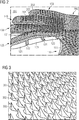
- Figure 1 shows an embodiment of a goalkeeper glove 100 according to the invention.
- the glove 100 comprises a thumb 110, an index finger 120, a middle finger 130, a ring finger 140 and a pinkie 150, the backsides of which are visible in Figure 1 .
- the backside of a finger or of a glove according to the invention as a whole denotes the side facing away from the palm of the wearer's hand when the glove is worn. In particular, such a backside is therefore also turned away from the palm of the wearer's hand when he is wearing the glove.
- the glove 100 further comprises a backside of the hand area 160 and a wrist area 170.
- the glove 100 comprises one or more gripping elements in the area of a frontside.
- the frontside of a glove according to the invention as opposed to a backside - denotes the side which is in contact with the inside of the wearer's hand when he is wearing the glove.
- the area of the glove which rests on the palm of the wearer's hand when wearing the glove belongs to the frontside of a glove according to the invention.
- at least gripping elements 121, 123, 125 are arranged on the frontside of the index finger 120, which may, for example, comprise special materials to increase the grip of the glove.
- Strips 122, 124 are arranged between the gripping elements 121, 123, 125.
- the strips 122, 124 may be arranged and adapted to facilitate a bending of the index finger 120.
- the strips 122, 124 may be arranged so that they are located above the joints of the wearer's index finger when wearing the glove 100.
- strips 122, 124 may comprise one or more particularly flexible materials.
- the glove 100 does not comprise a fastening mechanism.
- fastening mechanisms may be provided in other embodiments, in particular for example in the wrist area 170.
- Possible fastening mechanisms may comprise, but are not limited to, a hook- and-loop fastener.
- a glove such as the glove 100 may be obtained by applying various elements such as the gripping elements 121, 123, 125, 131 to a surface of an otherwise elastic preform of the glove, for example by gluing, sewing or ironing them on.
- different elements such as the gripping elements 121, 123, 125, 131 may also be fused to the preform for attachment.
- the preform may already be shaped so that it encloses the wearer's entire hand.
- the preform may be shaped in such a way that it does not enclose the entire hand of the wearer, but rather comprises gaps, holes and/or recesses in which the other elements such as the gripping elements 121, 123, 125, 131 may be placed and fixed.
- a glove such as the glove 100 comprises a flexible material, in particular a textile material or a polymeric material. Such material may be woven or knitted, in particular flat knitted. In an embodiment, at least part of a glove such as the glove 100 may be flat-knitted from a material consisting of 91% polyester, 8% elastane and 1% polyamide and thus comprising a mass per unit area of 86og/m2. However, a glove such as the glove 100 may also comprise a non-woven fabric, in particular one obtained by means of a so-called melt-blown or a so-called spun-bond process. In other embodiments, also a multilayer material may be used for a glove such as the glove 100, as will be further described in connection with Figure 11 .
- Glove 100 comprises a plurality of protrusions 201, 202, 203 (not all provided with reference signs) on its backside.
- the protrusions 201, 202, 203 protrude from the backside, i.e. they are for example attached to the backside. They extend in a first direction away from the back.
- the protrusions 201, 202, 203 are arranged in particular in the area of the knuckles, in the area of the thumb 110, in particular in the area of the base joint of the thumb, and in the area of the fingers 120, 130, 140, 150, but not in the area of the fingertips.
- protrusions 201, 202, 203 are arranged in an area that extends from an area between the thumb 110 and the index finger 120 to the wrist area 170.
- protrusions such as protrusions 201, 202, 203 are arranged additionally or alternatively in other areas of the backside.
- protrusions like the protrusions 201, 202, 203 may be arranged exclusively in the area of the knuckles, in the area of the backside of the hand 160 or in the area of the thumb 110, in particular in the area of the base joint of the thumb.
- Protrusions may also be arranged on the complete backside of a glove like glove 100.
- Protrusions may also be located on the frontside of a glove such as glove 100, in addition to or instead of gripping elements such as gripping elements 121, 123, 125 and/or strips such as strips 122, 124.
- Protrusions such as protrusions 201, 202, 203 may also protrude from an inner side of the glove, i.e. be located inside the glove and extend towards the surface of the wearer's hand.
- the protrusions 201, 202, 203 are individually attached to the backside of the glove 100, so they do not protrude from a common base element. This generally allows an even more flexible configuration of a glove according to the invention.
- the bases of protrusions such as protrusions 201, 202, 203 do not touch, while in others they do.
- at least two or more protrusions protrude from a common base element.
- all protrusions protrude from a common base element.
- the protrusions may also be attached to an inner layer (not shown) of a backside of a glove such as the glove 100 and extend through the outermost layer of the backside of the glove.
- protrusions such as protrusions 201, 202, 203 are applied to the backside of a glove such as glove 100 using a mould, for example using a one-piece metal mould.
- a mould for example using a one-piece metal mould.
- the one or more materials from which the protrusions are to be formed are first placed in the mould in a liquid state.
- the mould contains recesses that correspond to the desired protrusions - the recesses are, for example, negatives of the desired protrusions.
- air may be removed from the mould during and/or after this process.
- a press then presses the backside of the glove onto and/or into the metal mould with the liquid material inside. Due to the effect of heat and/or pressure, the liquid material diffuses at least into the surface of the backside of the glove.
- the protrusions are therefore applied to the backside of the glove by means of vulcanisation, for example.
- protrusions 201, 202, 203 comprise silicone.
- protrusions such as protrusions 201, 202, 203 may also comprise (soft) polymeric materials such as polyurethane or rubber.
- protrusions such as protrusions 201, 202, 203 may also comprise a layered structure.
- layers located on the backside of the glove could comprise silicone, which is particularly easy to apply to the backside of the glove, for example by vulcanisation as just described, while layers located in end portions of the protrusions could comprise rubber, so that abrasion from contact with a ball may be kept low.
- protrusions such as protrusions 201, 202, 203 comprise hardnesses in the range of 10-50 Shore A, preferably in the range of 15-35 Shore A, particularly preferably in the range of 20-30 Shore A, in particular a hardness of 26 Shore A.
- protrusions 201, 202, 203 may generally be varied individually and independently of each other across the backside of the glove.
- the intended use and/or the environment in which the glove will be used may be taken into account, for example, whether the glove will be used for indoor soccer or on a grass pitch.
- Figure 2 shows a detailed view of the glove 100 from Figure 1 , so the above explanations apply analogously.
- Figure 2 shows the plurality of protrusions 201, 202, 203 (not all provided with reference signs) in more detail.
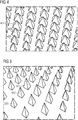
- the protrusions 201, 202, 203 may correspond to the individual protrusions of the plurality of protrusions 301, 302, 303 (not all provided with reference signs), which is shown schematically in Figure 3 .
- the protrusions 301, 302, 303 comprise a substantially rhomb-shaped or kite-shaped base. The four corners of each base are rounded, but need not be so in other embodiments.
- protrusions such as protrusions 301, 302, 303 may comprise any base, including non-quadrilateral ones, such as triangular, square, parallelogram-shaped - or more generally polygonal. Linear or round bases are also possible, as they are provided in the embodiments of Figures 6A-8C (see below).
- the protrusions 301, 302, 303 taper to a point, so their diameter varies along a first direction in which they extend.
- the resulting tip of the respective protrusions which in this case forms a respective end portion of the protrusions 301, 302, 303, is not located centrally above the respective base, so that the protrusions 301, 302, 303 are arranged in a tilted orientation (or in short: are tilted).
- the protrusions 301, 302, 303 are tilted towards one of the four corners of the respective base.
- protrusions such as protrusions 301, 302, 303 are arranged in a tilted orientation according to the invention or are tilted if the centre of volume of a protrusion does not lie with the centre of area of the associated base on a straight line which in turn is perpendicular to the base of the respective protrusion.
- Protrusions according to the invention are asymmetrical (at least) in this sense.
- the protrusions 301, 302, 303 each comprise four edges, which in turn each extend from a (rounded) corner of the rhomb-shaped or kite-shaped base of the corresponding protrusion 301, 302, 303 towards the end portion. These four edges are slightly concave in the embodiment of Figure 3 . In particular, those edges that protrude from the corner towards which the respective protrusion is tilted and those edges that start from the respective opposite corner are more concave than the other edges. Thus, the protrusions 301, 302, 303 are curved. All in all, the protrusions 301, 302, 303 thus resemble shark fins.
- FIG 4 shows a corresponding alternative embodiment of protrusions 401, 402, 403 (not all provided with reference signs) according to the invention.
- the protrusions 401, 402, 403 comprise a square base and taper to a point, so that they comprise a pyramid-like shape.
- protrusions 401, 402, 403 are tilted so that their end portions or tips are not located centrally above the square base.
- the protrusions 401, 402, 403 are not tilted towards a corner of the base as protrusions 301, 302, 303 of the embodiment of Figure 3 , but towards an edge of the square base.
- Figure 5 shows a plurality of protrusions 501, 502, 503 (not all provided with reference signs), each of which also has a square base and tapers to a point like a pyramid. But the protrusions 501, 502, 503 are tilted towards a corner of their respective square base. In addition, the protrusions 501, 502, 503 are further apart than the protrusions 401, 402, 403 of the embodiment of Figure 4 .
- the protrusions 301, 302, 303 of the embodiment of Figure 3 , the protrusions 401, 402, 403 of the embodiment of Figure 4 and the protrusions 501, 502, 503 vary in size but are all tilted in the same direction. In other embodiments, however, the orientation of the protrusions or their tilt may vary at least partially.
- Figures 6A and 6B show another possible embodiment of protrusions 601, 602, 603 (not all provided with reference signs) according to the invention.
- the protrusions 601, 602, 603 each comprise a linear base.
- the linear bases of protrusions 601, 602, 603 are parallel.
- the linear bases of protrusions 601, 602, 603 comprise a uniform waveform.
- the linear bases of protrusions 601, 602, 603 each describe two periods. In other embodiments, however, the linear bases of the protrusions 601, 602, 603 may also differ in length and shape.
- the protrusions 601, 602, 603 extend in a first direction.
- the protrusions 601, 602, 603 comprise an essentially wall-like or lamella-like shape. They do not taper to a point, their diameter does precisely not vary along the first direction. However, this may be the case in other embodiments.
- Figures 7A and 7B show another possible embodiment of protrusions 701, 702, 703 (not all provided with reference signs) according to the invention that extend in a first direction.
- protrusions 701, 702, 703 comprise a round base corresponding to an underside of a foot 720 of a protrusion 701, 702, 703.
- the foot 720 is followed in the first direction by a frustoconical element 719, which also comprises a smaller diameter than the foot 720.
- Protrusion 701, 702, 703 thus tapers in this area.
- a cylindrical element 718 is flush with the frustoconical element 719 in the first direction.
- the cylindrical element 718 is in turn flush with another frustoconical element 717, the diameter of which increases evenly along the first direction from the cylindrical element 718.
- Another cylindrical element 716 is flush with the other side of the frustoconical element 717.
- the cylindrical element 716 is accordingly larger in diameter than the cylindrical element 718.
- the cylindrical element 716 is followed by a sequence of elements 715, 714, 713, which substantially correspond to the elements 719, 718, 717.
- the element 713, which is thus frustoconical, is then followed, flush in the first direction, by another cylindrical element 712 whose diameter corresponds to that of the cylindrical element 716.
- the cylindrical element 712 is approximately twice as high as the cylindrical element 716.
- the cylindrical element 712 is followed in the first direction by an end portion of the protrusion 701, 702, 703, which has a spherical or ellipsoidal shape.
- the diameter of the protrusion 701, 702, 703 thus varies along the first direction.
- the partial taper of the protrusion 701, 702, 703 may act like a notch in the sense of the invention, i.e. facilitate a deformation of the protrusion 701, 702, 703.
- at least one protrusion comprises another type of notch which facilitates deformation. More generally, there could be a notch in a side of a protrusion from which the protrusion is tilted away. Notches may comprise any shape and depth.
- a perforation may extend through a protrusion to facilitate its deformation. Such a perforation is also to be understood as a notch in the sense of the invention.
- the protrusions 701, 702, 703 are preferably elastically or reversibly deformable, i.e. they resume their original shape as soon as no more force is applied to them.
- the plurality of protrusions 701, 702, 703 is arranged in such a way that the feet 720 of the protrusions 701, 702, 703 touch each other.
- the protrusions 701, 702, 703 are arranged uniformly and their feet 720 are arranged in a kind of checkerboard pattern.
- the plurality of protrusions 701, 702, 703 comprises protrusions 701, 702, 703 of at least two different heights. A difference in height may be due to the fact that some of the protrusions 701, 702, 703 are stretched or compressed in the first direction compared to others of the protrusions 701, 702, 703.
- a difference in height may also be caused by the fact that individual elements such as elements 712-719, in particular the cylindrical elements 718, 716, 714 and/or 712, of individual protrusions 701, 702, 703 are designed to be higher.
- the plurality of protrusions 701, 702, 703 is arranged in such a way that only protrusions 701, 702, 703 of the same height are in a row.
- the adjacent row only comprises protrusions 701, 702, 703 of the other of the two heights.
- this arrangement may allow the higher protrusions 701, 702, 703 to abut against the smaller protrusions 701, 702, 703 when deformed in a second direction.
- the smaller protrusions 701, 702, 703 may also abut against the higher protrusions 701, 702, 703 when deformed in a second direction.
- protrusions such as the protrusions 701, 702, 703 may be adapted to abut against each other, i.e., for example, against adjacent protrusions 701, 702, 703 when deformed in the second direction.
- Figures 8A-8C show another possible embodiment of protrusions 801, 802, 803 (not all provided with reference signs) according to the invention that extend in a first direction.
- Figure 8A shows the protrusions 801, 802, 803 before any deformation.
- Figures 8B and 8C show the protrusions 801, 802, 803 during a deformation, for example by contact with a ball moving in a direction comprising a component perpendicular to the first direction (in the plane of the image, for example, to the right).
- the protrusions 801, 802, 803 each comprise a round base corresponding to a lower end of a lowermost frustoconical element 815 or 825.
- the frustoconical elements 815, 825 grow wider along the first direction, thus their diameter increases.
- the lowermost frustoconical elements 815, 825 are flush with other frustoconical elements 814, 824, which also grow wider along the first direction.
- the frustoconical elements 814, 824 thereby widen more strongly than the frustoconical elements 815, 825; a slope in the first direction of a lateral surface of the frustoconical elements 814, 824 is thus smaller in amount than a slope in the first direction of a lateral surface of the frustoconical elements 815, 825.
- frustoconical elements 813, 823 are flush with the frustoconical elements 814, 824 in the first direction, which in turn widen even more strongly along the first direction than the frustoconical elements 814, 824.
- Cylindrical elements 812, 822 of low height are flush with the frustoconical elements 813, 823 in the first direction.
- These cylindrical elements 812, 822 are followed in the first direction by other frustoconical elements 811, 821 of low height.
- the frustoconical elements 811, 821 taper along the first direction, so relative to the cylindrical elements 812, 822 the diameter of the protrusions 801, 802, 803 decreases again, whereas it previously increased at the level of the elements 813-815, 823-825 along the first direction.
- the elements 811, 812, 813 and 821, 822, 823 form an end portion of the protrusions 801 and 802 respectively.
- the end portions of the protrusions 801, 802 and 803 comprise a funnel shape; if necessary, the funnel-shaped end portions may also comprise recesses on the top.
- This, in combination with a symmetrical, checkerboard-like arrangement of the protrusions 801, 802, 803 - similar to the protrusions 701, 702, 703 of the embodiments of Figures 7A and 7B - results in the protrusions 801, 802, 803 abutting against each other when deformed in a second direction that comprises a component perpendicular to the first direction.
- a deformation in the second direction may cause a frustoconical element 811, 821 of a protrusion 801, 802, 803 to come into contact with a frustoconical element 813, 823 of an adjacent protrusion 801, 802, 803.
- Deformation in the second direction causes an end portion of a protrusion 801, 802, 803 to move in a direction illustrated by an arrow 850.
- the end portion thus moves under an end portion of an adjacent protrusion 801, 802, 803.
- Adjacent protrusions 801, 802, 803 may thus support each other.
- each protrusion 801, 802, 803 abuts against an adjacent protrusion 801, 802, 803 in the second direction.
- the lateral surfaces of the protrusions or of individual elements such as elements 811-815, 821-825 may also be specially adapted with this effect in mind. For example, they may comprise a rough surface.
- each individual protrusion may be provided in any shape, in any size, in particular in any height, and/or in any orientation independently of the others of the plurality of protrusions.
- Each protrusion may also extend in any first direction.
- protrusions may be arranged in any number, at any distance, in any (distribution-)density and in any area. Therefore, the embodiment of Figures 1 and 2 , in which the protrusions 201, 202, 203 comprise the same shape and orientation - namely towards the tips of the fingers 120, 130, 140, 150 - but different sizes, is to be understood purely as an example.
- Figures 3-8C are also not to be understood in a limiting way; many other forms for protrusions according to the invention are conceivable, such as a bristle form, for example, as is known from toothbrushes or brooms and is shown schematically for protrusion 1401 of Figure 12 . Rather, all the mentioned parameters may be freely selected and varied, depending on the intended use of the glove and, if necessary, also on the needs of the wearer.
- Figures 9A-9C illustrates the advantages a glove with deformable protrusions according to the invention provides as compared to a glove entirely without protrusions ( Figure 9A ) as well as compared to a glove with non-deformable protrusions ( Figure 9B ).
- a ball 2000 hits a smooth backside 900 of a glove, i.e. one that is not provided with protrusions, at least partially parallel, as indicated by arrow 2050, the backside 900 of the glove and the ball 2000 touch in only one point, as shown in Figure 9A .
- the contact area is therefore very small.
- the backside 900 of the glove comprises a plurality of non-deformable protrusions 901', 902', 903'. 904', 905', 906', as shown in Figure 9B
- the backside 900 of the glove and the ball 2000 touch each other in three dimensions in a maximum of three points.
- this is illustrated as a contact of the ball 2000 with the protrusions 903' and 904'.
- the contact area between the backside 900 of the glove and the ball 2000 is therefore larger than in the case shown in Figure 9A , but still comparatively small.
- the backside 900 of the glove comprises a plurality of protrusions 901, 902, 903, 904, 905, 906 according to the invention which protrude from a backside 900 of the glove, extend in a first direction away from the backside 900 of the glove and are adapted to deform in a second direction that comprises a component perpendicular to the first direction (see also the detailed description of Figure 12 below), these are deformed by contact with the ball 2000.
- the contact area between the backside 900 of the glove and the ball 2000 may thus be increased:
- the ball also comes into contact, as illustrated in Figure 9C , with the lateral surfaces of multiple of the protrusions 901, 902, 903, 904, 905, 906 when they are deformed, especially when they are tilted and/or sheared in the second direction and/or bent towards the backside 900 of the glove.
- the lateral surfaces of the protrusions may also be specially adapted with this effect in mind. For example, they may comprise a rough surface to further increase the friction between the protrusions and the ball.
- the protrusions 901, 902, 903, 904, 905, 906 are deformed, for example tilted, sheared or bent, against a tilt they comprise. This may cause the protrusions 901, 902, 903, 904, 905, 906 to build up a greater restoring force, which in turn may increase the friction between the protrusions 901, 902, 903, 904, 905, 906 or the backside 900 of the glove in total, respectively, and the ball 2000.
- the contact area between the backside 900 of the glove and the ball 2000 may also be increased by deformation in any other direction that comprises a component perpendicular to the first direction.
- Protrusions according to the invention thus enable an increased stiction between the glove and the ball and may therefore improve ball control. This may also be demonstrated by means of a test procedure, which is explained below with reference to Figures 10A-10D .
- Test specimens such as test specimens 1000, 1100, 1200 of Figures 10A-10C are first pressed vertically onto a friction surface (or vice versa), for example onto friction surface 3000, which is shown in Figure 10D .
- the friction surface 3000 comprises a plurality of symmetrically arranged, rhomb-shaped protrusions 3010 (not all provided with reference signs).
- test specimen 1000, 1100, 1200 is pressed onto friction surface 3000 with a force of 100 N (or vice versa)
- test specimen 1000, 1100, 1200 and friction surface 3000 are moved relative to each other in a direction perpendicular to this force. This movement may occur at a speed of 100 mm/min, for example.
- the movement may be stopped, for example, after the test specimen 1000, 1100, 1200 and the friction surface 3000 have moved 50 mm relative to each other.
- Test specimen 1000 of Figure 10A comprises a plurality of protrusions 1001, 1002, 1003 (not all provided with reference signs) according to the invention, each of which comprises a rhomb-shaped base and tapers to a point.
- the protrusions 1001, 1002, 1003 vary in size but not in orientation.
- the protrusions 1001, 1002, 1003 are also not arranged in a tilted orientation.
- Test specimen 1100 of Figure 10B also comprises a plurality of protrusions 1101, 1102, 1103 (not all provided with reference signs) according to the invention.
- the protrusions 1101, 1102, 1103 essentially correspond to the protrusions 201, 202, 203 and 301, 302, 303 of the embodiments of Figures 1 , 2 and 3 , respectively.
- the protrusions 1101, 1102, 1103 are thus arranged in a tilted orientation, unlike the protrusions 1001, 1002, 1003 of the embodiment of Figure 10A .
- Test specimen 1200 of Figure 10C or its protrusions 1201, 1202, 1203, 1204 (not all provided with reference signs) is or are again known from the state of the art.
- Table 1 test specimen coefficient of static friction 1st pass 2nd pass 3rd pass 4th pass Average 1000 0.71 0.72 0.62 0.68 0.67 1100 0.85 0.86 0.85 0.87 0.86 1200 0.52 0.54 0.50 0.53 0.52
- the stiction of a backside of a glove with a ball may therefore be increased more strongly by protrusions according to the invention such as protrusions 1001, 1002, 1003, 1101, 1102, 1103 than by protrusions known from the state of the art such as protrusions 1201, 1202, 1203.
- the stiction may be increased to a particular high degree using tilted protrusions such as protrusions 1101, 1102, 1103.
- Figure 11 shows a possible layer structure of a backside 4000 of a glove.
- the backside 4000 of the glove comprises a top layer 4010, a middle layer 4020 and a bottom layer 4030.
- Layer 4010 may comprise polyester
- layer 4020 may comprise polyurethane, in particular polyurethane foam
- layer 4030 may comprise cotton.
- the layers 4010, 4020, 4030 may be designed in such a way that the backside 4000 of the glove consists of 48% polyester, 22% polyurethane foam and 30% cotton.
- Figure 12 shows possible second directions 5051, 5052, 5053, 5054, 5055 of a deformation of a protrusion 1401, each comprising a component 5051b, 5052b, 5053b (not shown because identical to direction 5053), 5054b, 5055b perpendicular to a first direction in which the protrusion 1401 extends away from a backside 5000 of a glove.
- directions 5051, 5052, 5054, 5055 each also comprise a component 5051a, 5052a, 5054a, 5055a which is parallel or antiparallel to the first direction.
- Direction 5053 on the other hand, does not comprise such a component which is oriented parallel or antiparallel to the first direction.
- Line 5060 illustrates the direction which is exactly at a right angle 5070 to the first direction, i.e. the direction in which protrusion 1401 extends.
- second directions 5051, 5052, 5053, 5054, 5055 only the second direction 5053 is exclusively parallel to line 5060 and thus perpendicular to the first direction.
- the other shown directions 5051, 5052, 5054, 5055 are not exclusively parallel to line 5060 and therefore not perpendicular to the first direction. But they comprise the components 5051b, 5052b, 5054b, 5055b which are perpendicular to the first direction, i.e. to the direction in which protrusion 1401 extends.
- a second direction comprises a component perpendicular to the first direction if it is not completely parallel or antiparallel to the first direction.
- the illustration of possible second directions in Figure 12 is not exhaustive, but merely serves to provide a better understanding.
Landscapes
- Health & Medical Sciences (AREA)
- General Health & Medical Sciences (AREA)
- Physical Education & Sports Medicine (AREA)
- Engineering & Computer Science (AREA)
- Textile Engineering (AREA)
- Gloves (AREA)
Abstract
Description
- The present invention relates to a glove, in particular a goalkeeper glove.
- Gloves have been known for a long time in many different forms. On the one hand, gloves may serve to protect the hands from a number of environmental influences such as cold, heat or friction. In particular, gloves may protect the hands from injuries caused by chemical or physical impacts, such as blows or cuts. For example, flexible elements are known from
EP 2 901 875 B1 , which may be applied to gloves to protect the hand from the effects of pressure. Preferably, the elements are each designed in the shape of a pyramid comprising a recess at the top such that the lateral surfaces of the pyramid-shaped element may fold inwards when the elements are subjected to pressure acting vertically on them. FromUS 10,342,274 B2 DE 10 2009 050 586 A1 . The wearer of the glove may thus grip a wide variety of objects more securely and, under certain circumstances, more firmly. - All these aspects play an important role especially also in the field of sports. Gloves are used in numerous sports, both to protect the hands, such as in ice hockey, and to support and improve the hands in their functionality, such as in golf. For example,
KR 101345655 B1 US 8,082,601 B2 (whose application documents were published asUS 2009/307820 A1 ) discloses a number of air-filled elements in the palm area of a glove, which may be of advantage when operating a club. - Last but not least, gloves have also been used in soccer and handball for decades. Goalkeeper gloves, especially in the area of the palms and the insides of the fingers, are usually designed in such a way that they enable the ball to be caught particularly securely. In addition, some elements are sometimes provided in or on the glove which may work together to prevent an overstretching of the fingers if they come into unfavourable contact with the ball, as is known, for example, from
EP 1378 273 B1 . A similar concept, although not explicitly related to soccer or handball, is also disclosed byJP 6321276 B1 CN 206777805U , inserts for a goalkeeper glove are known, which may be placed over the finger bones near the palm. Further gloves for soccer and American football, respectively, are known fromWO 2017/025110 A1 andUS 2007/209097 A1 . - However, in some game situations it may be hardly possible for the goalkeeper to catch the ball securely, for example when the ball is flying at some height or the goalkeeper is too far away from the ball to reach it with both hands. Instead, he must try to deflect the ball in some other way. In such cases, a goalkeeper often uses his clenched and extended fist. In traditional jargon, this is called "fisting away".
- However, such a fisting away offers considerably less control than a catching. Not only is the ball usually not with the goalkeeper after fisting away - unlike as with a successful catching. Also, the direction in which the ball is deflected by the fisting away may hardly be controlled sufficiently exactly. The goalkeeper risks with a fisting-away and the resulting lack of ball control that the ball jumps directly in front of the opponent's feet or is not deflected at all.
- The present invention is therefore based on the problem of providing a glove which increases the control of an object, in particular a ball, hitting the backside of the glove.
- This problem is at least partially solved by a glove according to independent claim 1.
- In an embodiment of the invention, a glove, in particular a goalkeeper glove, comprises a plurality of protrusions, wherein the protrusions protrude from a backside of the glove and extend in a first direction away from the backside, and wherein the protrusions are adapted to deform in a second direction that comprises a component perpendicular to the first direction.
- This provides a glove that offers a significantly increased level of control when fisting away a ball. By having a plurality of protrusions protrude from the backside of the glove and extending in a first direction away from the backside, the ball may interact with this plurality of protrusions instead of with an often largely smooth surface, thereby increasing friction between the glove and the ball and consequently ball control.
- The fact that the protrusions are adapted to deform in a second direction that comprises a component perpendicular to the first direction may further enhance this effect. Insofar as a deformability of the protrusions is referenced in the following, this refers to deformability under forces such as those which usually occur in ball sports such as handball and/or soccer, in particular upon contact between a goalkeeper glove and a ball. Moreover, protrusions according to the invention are preferably elastically or reversibly deformable, i.e. they resume their original shape as soon as no more force is applied to them. Furthermore, a deformation in the second direction thus refers to a deformation that acts at least partially perpendicular to the first direction in which the protrusions extend. Expressly not meant is a deformation which acts exclusively perpendicular to the first direction. In particular, the plurality of protrusions may be adapted to deform in the second direction upon contact of the backside of the glove with a ball such that a contact area of the glove with the ball is greater than without deformation of the plurality of protrusions. For example, the protrusions may be deformed by the ball contact in such a way that they follow the sphericity of the ball, both as a whole and individually.
- In particular, the contact area may also be increased by multiple of the plurality of protrusions being tilted and/or sheared in the second direction. In this case, the ball does not only come into contact with end portions and/or upper parts of the protrusions. Rather, the lateral surfaces of the respective protrusions then also abut at least partially against the ball. Especially in situations where the ball moves at least partially parallel to the glove surface, especially in the second direction, the protrusions may thus virtually "hook" into the ball.
- In some embodiments, at least one protrusion comprises a notch facilitating deformation. This may further enhance the described desirable effects caused by the general deformability of the protrusions. It may also allow to vary the stiffness and/or firmness of the respective protrusion in different directions. This may lead to the ball being deflected preferably in a certain direction.
- It may also serve better control when fisting away, if at least one protrusion is arranged in an orientation tilted towards the backside of the glove before a deformation. Where a tilted orientation (or in short, a tilt) is referenced in the following, a tilted orientation before a deformation is always meant. Due to a tilted orientation, protrusions may take stiffer and/or firmer effect in selected directions than in others and thus help to deflect the ball preferably in a certain direction. In particular, this may also be used to cause at least one protrusion to be deformed against its tilted orientation upon contact of the backside of the glove with a ball. This results in a particularly high restoring force in the respective protrusion, which may lead to even greater friction between the glove and the ball and thus further improve ball control.
- In some embodiments, a tilted orientation may be oriented towards the fingertips of the glove. A protrusion is oriented towards the fingertips of the glove in the sense of the invention even if it is only partially oriented towards the fingertips. In other words, it is sufficient if a vector describing the orientation of the protrusion comprises a non-zero component for the direction pointing along the extension direction of the fingers. Then, as described above, a particularly high friction between the ball and the glove develops when the ball hits the glove along a direction essentially determined by the extension direction of the fingers. It is precisely such constellations that very often occur in the game since the goalkeeper usually moves his hand towards the ball with his fingers (possibly clenched in a fist) in front by extending the corresponding arm. In other words, an orientation of the tilted orientation in the direction of the fingertips may favour the invention to develop its beneficial effects to a particularly high degree as often as possible during the game.
- At least one protrusion may comprise a kite, rhomb or linear base. As a result, the respective protrusion may take stiffer and/or firmer effect in some directions and thus develop a greater restoring force than in others. This may also help the ball being deflected preferably in a certain direction upon contact with the backside of the glove, thereby increasing ball control. Yet, in some embodiments, at least one protrusion comprises a round base in order to take equally stiff and/or firm effect in all directions.
- In some embodiments, a diameter of at least one protrusion may vary along the first direction. The diameter of a protrusion is the maximum possible distance between two points lying on a lateral surface of the protrusion and in a plane perpendicular to the first direction. For example, the at least one protrusion may taper towards an end portion opposite a base. This means that an upper part of a protrusion may be more easily deformed than a lower part, so that although the contact surface between the ball and the glove may increase as described above, the protrusions may still develop the necessary restoring force to ultimately hold (back) and deflect the ball. Conversely, the at least one protrusion may also taper towards the base, so that although it is easily deformed, it also allows for a particularly large contact area between the ball and the glove. In other embodiments, at least one protrusion may comprise a shape in which a diameter alternately increases and decreases. This may allow a particularly precise adjustment of the deformability of the corresponding protrusion and its contact area with a ball.
- In some embodiments, an end portion - which by definition always faces a base of a protrusion in the first direction - of at least one protrusion may comprise a spherical, ellipsoidal or funnel shape. In this way, injuries to third parties by the protrusions may be avoided and/or the possible contact area of the at least one protrusion with a ball may be further adjusted, for example enlarged.
- At least one protrusion may be adapted to abut against an adjacent protrusion when it is deformed in the second direction. This may be achieved, for example, by having end portions of protrusions comprise a larger diameter than a respective base, such as when the end portions comprise a spherical shape, an ellipsoidal shape or a funnel shape as just described. When adjacent protrusions abut against each other, they may support each other and thus develop a greater restoring force, which in turn may lead to increased friction with the ball and thus to improved ball control.
- Also, protrusions - both for this purpose and in general - may differ in size, in particular height, shape and/or orientation. The height of a protrusion denotes its extension in the first direction. The orientation of a protrusion is the direction of its tilted orientation. The number of protrusions per unit area, i.e. the (distribution-)density of the protrusions, may also be varied across the backside of the glove. This allows a high degree of flexibility in the design of a glove according to the invention, so that it may be adapted to the respective purposes and needs. For example, the size, shape, orientation and/or (distribution)-density of the protrusions may be varied at will - if necessary even individually for a particular wearer - in order to take greater advantage of the above-described beneficial effects of the deformable, tilted protrusions in certain areas of the glove and/or in certain directions than in others.
- It may be particularly advantageous to provide the protrusions in the area of the knuckles, as this is the area that typically comes into contact with the ball when fisting away. But also in the area of the backside of the hand and/or in the area of the thumb, in particular in the area of the base joint of the thumb, the deformable, tilted protrusions according to the invention may be advantageous, because the wearer of the glove cannot always hit the ball with the knuckles in front. In some situations, the ball will hit the backside of the hand or even the outside of the thumb. It may be important that a glove also allows a high degree of ball control in such cases, which may be ensured by protrusions according to the invention in these areas.
- Additionally or alternatively, at least one protrusion may also be curved. This may also favour that the respective protrusion may be more easily deformed by the ball, for example tilted, sheared or bent, and still build up sufficient restoring force.
- Also, each protrusion may be individually attached to the backside of the glove, so protrusions do not protrude from a common base element. Not only may the above-mentioned freedom of design be further increased. It also makes it easier to repair or replace individual protrusions, which may have a positive effect on the durability and environmental friendliness of the gloves. In particular, it may also be avoided that a flat base element (from which the plurality of protrusions according to the invention would then protrude) has to be attached to the glove, which could restrict the freedom of movement of the hand. If each protrusion is individually attached to the backside of the glove, the wearing comfort of the glove may be increased without the protrusions losing any functionality.
- In some embodiments, at least one protrusion comprises silicone. It has been found that silicone is particularly suitable for the protrusions according to the invention. Therefore, in some embodiments, several, if not all, protrusions are made of silicone.
- The protrusions may comprise a hardness in the range of 10-50 Shore A, preferably in the range of 15-35 Shore A, especially preferably in the range of 20-30 Shore A, in particular a hardness of 26 Shore A. It has been found that the purpose of the invention may be achieved particularly well with these hardnesses, as the protrusions are sufficiently soft to be easily deformed, for example tilted, sheared or bent, but still stiff or firm enough to develop the necessary tension and thus restoring force to effectively hold (back) and deflect the ball.
- As mentioned, the protrusions are preferably elastically or reversibly deformable, i.e. they resume their original shape as soon as no more force is applied to them.
- Possible embodiments of the present invention are described in more detail in the following detailed description with reference to the following Figures:
- Figure 1:
- Exemplary embodiment of a goalkeeper glove with a plurality of protrusions, wherein the protrusions protrude from a backside of the glove and extend in a first direction away from the backside, and wherein the protrusions are adapted to deform in a second direction that comprises a component perpendicular to the first direction;
- Figure 2:
- Detailed view of the embodiment of
Figure 1 ; - Figure 3:
- Schematic representation of a plurality of protrusions;
- Figure 4:
- Schematic representation of another plurality of protrusions;
- Figure 5:
- Schematic representation of another plurality of protrusions;
- Figures 6A, 6B:
- Schematic representations of another plurality of protrusions;
- Figures 7A, 7B:
- Schematic representations of another plurality of protrusions;
- Figures 8A-8C:
- Schematic representations of another plurality of protrusions;
- Figures 9A-9C:
- Schematic diagram of a possible mode of operation of a plurality of protrusions;
- Figures 10A, 10B:
- Test specimens with various pluralities of protrusions;
- Figure 10C:
- Test specimen with a plurality of protrusions known from the state of the art;
- Figure 10D:
- Friction surface known from the state of the art for use in determining a coefficient of static friction;
- Figure 11:
- Schematic representation of a layered structure of a backside of a glove;
- Figure 12:
- Schematic representation of possible deformation directions.
- For the sake of brevity, only a few embodiments will be described below. The person skilled in the art will recognize that the features described with reference to these specific embodiments may be modified and combined in different ways and that individual features may also be omitted. The general explanations in the sections above also apply to the more detailed explanations below.
-
Figure 1 shows an embodiment of agoalkeeper glove 100 according to the invention. Theglove 100 comprises athumb 110, anindex finger 120, amiddle finger 130, aring finger 140 and apinkie 150, the backsides of which are visible inFigure 1 . The backside of a finger or of a glove according to the invention as a whole denotes the side facing away from the palm of the wearer's hand when the glove is worn. In particular, such a backside is therefore also turned away from the palm of the wearer's hand when he is wearing the glove. Theglove 100 further comprises a backside of thehand area 160 and awrist area 170. - The
glove 100 comprises one or more gripping elements in the area of a frontside. The frontside of a glove according to the invention - as opposed to a backside - denotes the side which is in contact with the inside of the wearer's hand when he is wearing the glove. In particular, the area of the glove which rests on the palm of the wearer's hand when wearing the glove belongs to the frontside of a glove according to the invention. In the embodiment ofFigure 1 , for example, at leastgripping elements index finger 120, which may, for example, comprise special materials to increase the grip of the glove. There is also at least onegripping element 131 arranged on the frontside of themiddle finger 130.Strips gripping elements strips index finger 120. For example, thestrips glove 100. Alternatively or additionally, strips 122, 124 may comprise one or more particularly flexible materials. - The
glove 100 does not comprise a fastening mechanism. However, fastening mechanisms may be provided in other embodiments, in particular for example in thewrist area 170. Possible fastening mechanisms may comprise, but are not limited to, a hook- and-loop fastener. - In some embodiments, a glove such as the
glove 100 may be obtained by applying various elements such as thegripping elements gripping elements gripping elements - In some embodiments, a glove such as the
glove 100 comprises a flexible material, in particular a textile material or a polymeric material. Such material may be woven or knitted, in particular flat knitted. In an embodiment, at least part of a glove such as theglove 100 may be flat-knitted from a material consisting of 91% polyester, 8% elastane and 1% polyamide and thus comprising a mass per unit area of 86og/m2. However, a glove such as theglove 100 may also comprise a non-woven fabric, in particular one obtained by means of a so-called melt-blown or a so-called spun-bond process. In other embodiments, also a multilayer material may be used for a glove such as theglove 100, as will be further described in connection withFigure 11 . -
Glove 100 comprises a plurality ofprotrusions protrusions Figure 1 , theprotrusions thumb 110, in particular in the area of the base joint of the thumb, and in the area of thefingers protrusions thumb 110 and theindex finger 120 to thewrist area 170. In other embodiments, protrusions such asprotrusions protrusions hand 160 or in the area of thethumb 110, in particular in the area of the base joint of the thumb. Protrusions may also be arranged on the complete backside of a glove likeglove 100. Protrusions may also be located on the frontside of a glove such asglove 100, in addition to or instead of gripping elements such asgripping elements strips protrusions - The
protrusions glove 100, so they do not protrude from a common base element. This generally allows an even more flexible configuration of a glove according to the invention. In some embodiments, the bases of protrusions such asprotrusions glove 100 and extend through the outermost layer of the backside of the glove. - In some embodiments, protrusions such as
protrusions glove 100 using a mould, for example using a one-piece metal mould. For example, the one or more materials from which the protrusions are to be formed are first placed in the mould in a liquid state. The mould contains recesses that correspond to the desired protrusions - the recesses are, for example, negatives of the desired protrusions. In addition, air may be removed from the mould during and/or after this process. A press then presses the backside of the glove onto and/or into the metal mould with the liquid material inside. Due to the effect of heat and/or pressure, the liquid material diffuses at least into the surface of the backside of the glove. The protrusions are therefore applied to the backside of the glove by means of vulcanisation, for example. - The
protrusions protrusions protrusions - In some embodiments, protrusions such as
protrusions - The person skilled in the art understands that the material composition and hardness of protrusions such as
protrusions -
Figure 2 shows a detailed view of theglove 100 fromFigure 1 , so the above explanations apply analogously. In particular,Figure 2 shows the plurality ofprotrusions - At least in their shape, the
protrusions protrusions Figure 3 . Theprotrusions protrusions Figures 6A-8C (see below). - The
protrusions protrusions protrusions protrusions protrusions - The
protrusions corresponding protrusion Figure 3 . In particular, those edges that protrude from the corner towards which the respective protrusion is tilted and those edges that start from the respective opposite corner are more concave than the other edges. Thus, theprotrusions protrusions - In principle, however, any other shapes are also possible for protrusions according to the invention.
Figure 4 shows a corresponding alternative embodiment ofprotrusions protrusions protrusions protrusions protrusions Figure 3 , but towards an edge of the square base. - On the other hand,
Figure 5 shows a plurality ofprotrusions protrusions protrusions protrusions Figure 4 . - The
protrusions Figure 3 , theprotrusions Figure 4 and theprotrusions -
Figures 6A and 6B show another possible embodiment ofprotrusions Figure 6B , theprotrusions protrusions protrusions Figures 6A and 6B , the linear bases ofprotrusions protrusions - From the linear bases the
protrusions protrusions -
Figures 7A and 7B show another possible embodiment ofprotrusions Figure 7B ,protrusions foot 720 of aprotrusion foot 720 is followed in the first direction by afrustoconical element 719, which also comprises a smaller diameter than thefoot 720.Protrusion cylindrical element 718 is flush with thefrustoconical element 719 in the first direction. Thecylindrical element 718 is in turn flush with anotherfrustoconical element 717, the diameter of which increases evenly along the first direction from thecylindrical element 718. Anothercylindrical element 716 is flush with the other side of thefrustoconical element 717. Thecylindrical element 716 is accordingly larger in diameter than thecylindrical element 718. Thecylindrical element 716 is followed by a sequence ofelements elements element 713, which is thus frustoconical, is then followed, flush in the first direction, by anothercylindrical element 712 whose diameter corresponds to that of thecylindrical element 716. However, thecylindrical element 712 is approximately twice as high as thecylindrical element 716. Thecylindrical element 712 is followed in the first direction by an end portion of theprotrusion - In total, the diameter of the
protrusion protrusion protrusion - The
protrusions - The plurality of
protrusions feet 720 of theprotrusions protrusions feet 720 are arranged in a kind of checkerboard pattern. The plurality ofprotrusions protrusions protrusions protrusions cylindrical elements individual protrusions protrusions protrusions - In combination with the spherical or
ellipsoidal end portions 711 of theprotrusions higher protrusions smaller protrusions smaller protrusions higher protrusions protrusions adjacent protrusions -
Figures 8A-8C show another possible embodiment ofprotrusions Figure 8A shows theprotrusions Figures 8B and8C , on the other hand, show theprotrusions protrusions frustoconical element frustoconical elements frustoconical elements frustoconical elements frustoconical elements frustoconical elements frustoconical elements frustoconical elements frustoconical elements frustoconical elements frustoconical elements Cylindrical elements frustoconical elements cylindrical elements frustoconical elements frustoconical elements cylindrical elements protrusions - The
elements protrusions protrusions protrusions protrusions Figures 7A and 7B - results in theprotrusions frustoconical element protrusion frustoconical element adjacent protrusion Figure 8C . Deformation in the second direction causes an end portion of aprotrusion arrow 850. In particular, the end portion thus moves under an end portion of anadjacent protrusion Adjacent protrusions Figure 8B : eachprotrusion adjacent protrusion - In general, the skilled person understands from the foregoing that each individual protrusion may be provided in any shape, in any size, in particular in any height, and/or in any orientation independently of the others of the plurality of protrusions. Each protrusion may also extend in any first direction. Likewise, protrusions may be arranged in any number, at any distance, in any (distribution-)density and in any area. Therefore, the embodiment of
Figures 1 and2 , in which theprotrusions fingers Figures 3-8C are also not to be understood in a limiting way; many other forms for protrusions according to the invention are conceivable, such as a bristle form, for example, as is known from toothbrushes or brooms and is shown schematically forprotrusion 1401 ofFigure 12 . Rather, all the mentioned parameters may be freely selected and varied, depending on the intended use of the glove and, if necessary, also on the needs of the wearer. -
Figures 9A-9C , in particularFigure 9C , illustrates the advantages a glove with deformable protrusions according to the invention provides as compared to a glove entirely without protrusions (Figure 9A ) as well as compared to a glove with non-deformable protrusions (Figure 9B ). - For example, if a
ball 2000 hits asmooth backside 900 of a glove, i.e. one that is not provided with protrusions, at least partially parallel, as indicated byarrow 2050, thebackside 900 of the glove and theball 2000 touch in only one point, as shown inFigure 9A . The contact area is therefore very small. - If the
backside 900 of the glove comprises a plurality ofnon-deformable protrusions Figure 9B , thebackside 900 of the glove and theball 2000 touch each other in three dimensions in a maximum of three points. In the two-dimensional diagram inFigure 9B , this is illustrated as a contact of theball 2000 with theprotrusions 903' and 904'. The contact area between thebackside 900 of the glove and theball 2000 is therefore larger than in the case shown inFigure 9A , but still comparatively small. - However, if the
backside 900 of the glove comprises a plurality ofprotrusions backside 900 of the glove, extend in a first direction away from thebackside 900 of the glove and are adapted to deform in a second direction that comprises a component perpendicular to the first direction (see also the detailed description ofFigure 12 below), these are deformed by contact with theball 2000. In particular, as shown inFigure 9C , they may be deformed in the second direction, in particular tilted, sheared or bent; theball 2000 may thus "pull" theprotrusions protrusions backside 900 of the glove and theball 2000 may thus be increased: Instead of only the end portions or tips of individual protrusions, as illustrated inFigure 9B , the ball also comes into contact, as illustrated inFigure 9C , with the lateral surfaces of multiple of theprotrusions backside 900 of the glove. In some embodiments, the lateral surfaces of the protrusions may also be specially adapted with this effect in mind. For example, they may comprise a rough surface to further increase the friction between the protrusions and the ball. - In the embodiment of
Figure 9C , theprotrusions protrusions protrusions backside 900 of the glove in total, respectively, and theball 2000. However, the contact area between thebackside 900 of the glove and theball 2000 may also be increased by deformation in any other direction that comprises a component perpendicular to the first direction. - Protrusions according to the invention thus enable an increased stiction between the glove and the ball and may therefore improve ball control. This may also be demonstrated by means of a test procedure, which is explained below with reference to
Figures 10A-10D . Test specimens such astest specimens Figures 10A-10C are first pressed vertically onto a friction surface (or vice versa), for example ontofriction surface 3000, which is shown inFigure 10D . Thefriction surface 3000 comprises a plurality of symmetrically arranged, rhomb-shaped protrusions 3010 (not all provided with reference signs). For example, while thetest specimen friction surface 3000 with a force of 100 N (or vice versa),test specimen friction surface 3000 are moved relative to each other in a direction perpendicular to this force. This movement may occur at a speed of 100 mm/min, for example. Furthermore, the movement may be stopped, for example, after thetest specimen friction surface 3000 have moved 50 mm relative to each other. -
Test specimen 1000 ofFigure 10A comprises a plurality ofprotrusions 1001, 1002, 1003 (not all provided with reference signs) according to the invention, each of which comprises a rhomb-shaped base and tapers to a point. Theprotrusions 1001, 1002, 1003 vary in size but not in orientation. Theprotrusions 1001, 1002, 1003 are also not arranged in a tilted orientation. -
Test specimen 1100 ofFigure 10B also comprises a plurality ofprotrusions 1101, 1102, 1103 (not all provided with reference signs) according to the invention. Theprotrusions 1101, 1102, 1103 essentially correspond to theprotrusions Figures 1 ,2 and 3 , respectively. In particular, theprotrusions 1101, 1102, 1103 are thus arranged in a tilted orientation, unlike theprotrusions 1001, 1002, 1003 of the embodiment ofFigure 10A . -
Test specimen 1200 ofFigure 10C , or itsprotrusions - When the coefficient of static friction of the three
test specimens Table 1 test specimen coefficient of static friction 1st pass 2nd pass 3rd pass 4th pass Average 1000 0.71 0.72 0.62 0.68 0.67 1100 0.85 0.86 0.85 0.87 0.86 1200 0.52 0.54 0.50 0.53 0.52 - The stiction of a backside of a glove with a ball may therefore be increased more strongly by protrusions according to the invention such as
protrusions protrusions protrusions 1101, 1102, 1103. -
Figure 11 shows a possible layer structure of abackside 4000 of a glove. Thebackside 4000 of the glove comprises atop layer 4010, amiddle layer 4020 and abottom layer 4030. On thetop layer 4010 there are arrangedprotrusions Layer 4010 may comprise polyester,layer 4020 may comprise polyurethane, in particular polyurethane foam, andlayer 4030 may comprise cotton. Thelayers backside 4000 of the glove consists of 48% polyester, 22% polyurethane foam and 30% cotton. -
Figure 12 shows possiblesecond directions protrusion 1401, each comprising acomponent protrusion 1401 extends away from abackside 5000 of a glove. In addition,directions component Direction 5053, on the other hand, does not comprise such a component which is oriented parallel or antiparallel to the first direction.Line 5060 illustrates the direction which is exactly at aright angle 5070 to the first direction, i.e. the direction in whichprotrusion 1401 extends. Of the shownsecond directions second direction 5053 is exclusively parallel toline 5060 and thus perpendicular to the first direction. The other showndirections line 5060 and therefore not perpendicular to the first direction. But they comprise thecomponents protrusion 1401 extends. In other words, a second direction comprises a component perpendicular to the first direction if it is not completely parallel or antiparallel to the first direction. The illustration of possible second directions inFigure 12 is not exhaustive, but merely serves to provide a better understanding. - In the following, further embodiments are described to facilitate the understanding of the invention:
- 1. A glove (100), in particular a goalkeeper glove,
- a. with a plurality of protrusions (201, 202, 203, 301, 302, 303, 401, 402, 403, 501, 502, 503, 601, 602, 603, 701, 702, 703, 801, 802, 803, 901, 902, 903, 1001, 1002, 1003, 1101, 1102, 1103, 1301, 1302, 1303, 1401)
- b. wherein the protrusions (201, 202, 203, 301, 302, 303, 401, 402, 403, 501, 502, 503, 601, 602, 603, 701, 702, 703, 801, 802, 803, 901, 902, 903, 1001, 1002, 1003, 1101, 1102, 1103, 1301, 1302, 1303, 1401) protrude from a backside of the glove (100) and extend in a first direction away from the backside, and
- c. wherein the protrusions (201, 202, 203, 301, 302, 303, 401, 402, 403, 501, 502, 503, 601, 602, 603, 701, 702, 703, 801, 802, 803, 901, 902, 903, 1001, 1002, 1003, 1101, 1102, 1103, 1301, 1302, 1303, 1401) are adapted to deform in a second direction (5051, 5052, 5053, 5054, 5055) that comprises a component (5051b, 5052b, 5054b, 5055b) perpendicular to the first direction.
- 2. Glove (100) according to embodiment 1, wherein the plurality of protrusions (201, 202, 203, 301, 302, 303, 401, 402, 403, 501, 502, 503, 601, 602, 603, 701, 702, 703, 801, 802, 803, 901, 902, 903, 1001, 1002, 1003, 1101, 1102, 1103, 1301, 1302, 1303, 1401) is adapted to deform in the second direction (5051, 5052, 5053, 5054, 5055) upon contact of the backside of the glove (100) with a ball (2000) such that a contact area of the glove (100) with the ball (2000) is larger than without a deformation of the plurality of protrusions (201, 202, 203, 301, 302, 303, 401, 402, 403, 501, 502, 503, 601, 602, 603, 701, 702, 703, 801, 802, 803, 901, 902, 903, 1001, 1002, 1003, 1101, 1102, 1103, 1301, 1302, 1303, 1401).
- 3. Glove (100) according to embodiment 2, wherein the contact area is increased by multiple of the plurality of protrusions (201, 202, 203, 301, 302, 303, 401, 402, 403, 501, 502, 503, 601, 602, 603, 701, 702, 703, 801, 802, 803, 901, 902, 903, 1001, 1002, 1003, 1101, 1102, 1103, 1301, 1302, 1303, 1401) being tilted and/or sheared in the second direction (5051, 5052, 5053, 5054, 5055).
- 4. Glove (100) according to any of the preceding embodiments, wherein at least one protrusion (201, 202, 203, 301, 302, 303, 401, 402, 403, 501, 502, 503, 601, 602, 603, 701, 702, 703, 801, 802, 803, 901, 902, 903, 1001, 1002, 1003, 1101, 1102, 1103, 1301, 1302, 1303, 1401) comprises a notch facilitating deformation.
- 5. Glove (100) according to any of the preceding embodiments, wherein at least one protrusion (201, 202, 203, 301, 302, 303, 401, 402, 403, 501, 502, 503, 601, 602, 603, 701, 702, 703, 801, 802, 803, 901, 902, 903, 1001, 1002, 1003, 1101, 1102, 1103, 1301, 1302, 1303, 1401) is arranged in an orientation tilted towards the backside of the glove (100) before deformation.
- 6. Glove (100) according to embodiment 5, wherein the tilted orientation is oriented towards the fingertips of the glove (100).
- 7. Glove (100) according to embodiment 5 or 6, wherein the at least one protrusion (201, 202, 203, 301, 302, 303, 401, 402, 403, 501, 502, 503, 601, 602, 603, 701, 702, 703, 801, 802, 803, 901, 902, 903, 1001, 1002, 1003, 1101, 1102, 1103, 1301, 1302, 1303, 1401) is deformed against its tilted orientation upon contact of the backside of the glove (100) with a ball (2000).
- 8. Glove (100) according to any of the preceding embodiments, wherein at least one protrusion (201, 202, 203, 301, 302, 303, 401, 402, 403, 501, 502, 503, 601, 602, 603, 701, 702, 703, 801, 802, 803, 901, 902, 903, 1001, 1002, 1003, 1101, 1102, 1103, 1301, 1302, 1303, 1401) comprises a kite, rhomb, linear or round base.
- 9. Glove (100) according to any of the preceding embodiments, wherein a diameter of at least one protrusion (201, 202, 203, 301, 302, 303, 401, 402, 403, 501, 502, 503, 601, 602, 603, 701, 702, 703, 801, 802, 803, 901, 902, 903, 1001, 1002, 1003, 1101, 1102, 1103, 1301, 1302, 1303, 1401) varies along the first direction.
- 10. Glove (100) according to any of the preceding embodiments, wherein an end portion of at least one protrusion (201, 202, 203, 301, 302, 303, 401, 402, 403, 501, 502, 503, 601, 602, 603, 701, 702, 703, 801, 802, 803, 901, 902, 903, 1001, 1002, 1003, 1101, 1102, 1103, 1301, 1302, 1303, 1401) comprises a spherical shape, an ellipsoidal shape or a funnel shape.
- 11. Glove (100) according to any of the preceding embodiments, wherein at least one protrusion (201, 202, 203, 301, 302, 303, 401, 402, 403, 501, 502, 503, 601, 602, 603, 701, 702, 703, 801, 802, 803, 901, 902, 903, 1001, 1002, 1003, 1101, 1102, 1103, 1301, 1302, 1303, 1401) is adapted to abut against an adjacent protrusion (201, 202, 203, 301, 302, 303, 401, 402, 403, 501, 502, 503, 601, 602, 603, 701), 702, 703, 801, 802, 803, 901, 902, 903, 1001, 1002, 1003, 1101, 1102, 1103, 1301, 1302, 1303, 1401) when the at least one protrusion (201, 202, 203, 301, 302, 303, 401, 402, 403, 501, 502, 503, 601, 602, 603, 701, 702, 703, 801, 802, 803, 901, 902, 903, 1001, 1002, 1003, 1101, 1102, 1103, 1301, 1302, 1303, 1401) is deformed in the second direction (5051, 5052, 5053, 5054, 5055).
- 12. Glove (100) according to any of the preceding embodiments, wherein at least one protrusion (201, 202, 203, 301, 302, 303, 401, 402, 403, 501, 502, 503, 601, 602, 603, 701, 702, 703, 801, 802, 803, 901, 902, 903, 1001, 1002, 1003, 1101, 1102, 1103, 1301, 1302, 1303, 1401) is curved.
- 13. Glove (100) according to any of the preceding embodiments, wherein at least two protrusions (201, 202, 203, 301, 302, 303, 401, 402, 403, 501, 502, 503, 601, 602, 603, 701, 702, 703, 801, 802, 803, 901, 902, 903, 1001, 1002, 1003, 1101, 1102, 1103, 1301, 1302, 1303, 1401) differ in size, in particular height, shape and/or orientation.
- 14. Glove (100) according to any of the preceding embodiments, wherein each protrusion (201, 202, 203, 301, 302, 303, 401, 402, 403, 501, 502, 503, 601, 602, 603, 701, 702, 703, 801, 802, 803, 901, 902, 903, 1001, 1002, 1003, 1101, 1102, 1103, 1301, 1302, 1303, 1401) is individually attached to the backside of the glove (100).
- 15. Glove (100) according to any of the preceding embodiments, wherein the protrusions (201, 202, 203, 301, 302, 303, 401, 402, 403, 501, 502, 503, 601, 602, 603, 701, 702, 703, 801, 802, 803, 901, 902, 903, 1001, 1002, 1003, 1101, 1102, 1103, 1301, 1302, 1303, 1401) are arranged in the area of the knuckles of the fingers, in the area of the backside of the hand (160) and/or in the area of the thumb (110), in particular in the area of the base joint of the thumb.
- 16. Glove (100) according to any of the preceding embodiments, wherein the number of protrusions (201, 202, 203, 301, 302, 303, 401, 402, 403, 501, 502, 503, 601, 602, 603, 701, 702, 703, 801, 802, 803, 901, 902, 903, 1001, 1002, 1003, 1101, 1102, 1103, 1301, 1302, 1303, 1401) per unit area varies across the backside of the glove (100).
- 17. Glove (100) according to any of the preceding embodiments, wherein at least one protrusion (201, 202, 203, 301, 302, 303, 401, 402, 403, 501, 502, 503, 601, 602, 603, 701, 702, 703, 801, 802, 803, 901, 902, 903, 1001, 1002, 1003, 1101, 1102, 1103, 1301, 1302, 1303, 1401) comprises silicone.
- 18. Glove (100) according to any of the preceding embodiments, wherein at least one protrusion (201, 202, 203, 301, 302, 303, 401, 402, 403, 501, 502, 503, 601, 602, 603, 701, 702, 703, 801, 802, 803, 901, 902, 903, 1001, 1002, 1003, 1101, 1102, 1103, 1301, 1302, 1303, 1401) comprises a hardness in the range of 10-50 Shore A, preferably in the range of 15-35 Shore A, particularly preferably in the range of 20-30 Shore A, in particular a hardness of 26 Shore A.
Claims (15)
- A glove (100), in particular a goalkeeper glove,a. with a plurality of protrusions (201, 202, 203, 301, 302, 303, 401, 402, 403, 501, 502, 503, 601, 602, 603, 701, 702, 703, 801, 802, 803, 901, 902, 903, 1001, 1002, 1003, 1101, 1102, 1103, 1301, 1302, 1303, 1401)b. wherein the protrusions (201, 202, 203, 301, 302, 303, 401, 402, 403, 501, 502, 503, 601, 602, 603, 701, 702, 703, 801, 802, 803, 901, 902, 903, 1001, 1002, 1003, 1101, 1102, 1103, 1301, 1302, 1303, 1401) protrude from a backside of the glove (100) and extend in a first direction away from the backside, andc. wherein the protrusions (201, 202, 203, 301, 302, 303, 401, 402, 403, 501, 502, 503, 601, 602, 603, 701, 702, 703, 801, 802, 803, 901, 902, 903, 1001, 1002, 1003, 1101, 1102, 1103, 1301, 1302, 1303, 1401) are adapted to deform in a second direction (5051, 5052, 5053, 5054, 5055) that comprises a component (5051b, 5052b, 5054b, 5055b) perpendicular to the first direction.
- Glove (100) according to claim 1, wherein the plurality of protrusions (201, 202, 203, 301, 302, 303, 401, 402, 403, 501, 502, 503, 601, 602, 603, 701, 702, 703, 801, 802, 803, 901, 902, 903, 1001, 1002, 1003, 1101, 1102, 1103, 1301, 1302, 1303, 1401) is adapted to deform in the second direction (5051, 5052, 5053, 5054, 5055) upon contact of the backside of the glove (100) with a ball (2000) such that a contact area of the glove (100) with the ball (2000) is larger than without a deformation of the plurality of protrusions (201, 202, 203, 301, 302, 303, 401, 402, 403, 501, 502, 503, 601, 602, 603, 701, 702, 703, 801, 802, 803, 901, 902, 903, 1001, 1002, 1003, 1101, 1102, 1103, 1301, 1302, 1303, 1401).
- Glove (100) according to claim 2, wherein the contact area is increased by multiple of the plurality of protrusions (201, 202, 203, 301, 302, 303, 401, 402, 403, 501, 502, 503, 601, 602, 603, 701, 702, 703, 801, 802, 803, 901, 902, 903, 1001, 1002, 1003, 1101, 1102, 1103, 1301, 1302, 1303, 1401) being tilted and/or sheared in the second direction (5051, 5052, 5053, 5054, 5055).
- Glove (100) according to any of the preceding claims, wherein at least one protrusion (201, 202, 203, 301, 302, 303, 401, 402, 403, 501, 502, 503, 601, 602, 603, 701, 702, 703, 801, 802, 803, 901, 902, 903, 1001, 1002, 1003, 1101, 1102, 1103, 1301, 1302, 1303, 1401) comprises a notch facilitating deformation.
- Glove (100) according to any of the preceding claims, wherein at least one protrusion (201, 202, 203, 301, 302, 303, 401, 402, 403, 501, 502, 503, 601, 602, 603, 701, 702, 703, 801, 802, 803, 901, 902, 903, 1001, 1002, 1003, 1101, 1102, 1103, 1301, 1302, 1303, 1401) is arranged in an orientation tilted towards the backside of the glove (100) before deformation.
- Glove (100) according to claim 5, wherein the tilted orientation is oriented towards the fingertips of the glove (100).
- Glove (100) according to claim 5 or 6, wherein the at least one protrusion (201, 202, 203, 301, 302, 303, 401, 402, 403, 501, 502, 503, 601, 602, 603, 701, 702, 703, 801, 802, 803, 901, 902, 903, 1001, 1002, 1003, 1101, 1102, 1103, 1301, 1302, 1303, 1401) is deformed against its tilted orientation upon contact of the backside of the glove (100) with a ball (2000).
- Glove (100) according to any of the preceding claims, wherein at least one protrusion (201, 202, 203, 301, 302, 303, 401, 402, 403, 501, 502, 503, 601, 602, 603, 701, 702, 703, 801, 802, 803, 901, 902, 903, 1001, 1002, 1003, 1101, 1102, 1103, 1301, 1302, 1303, 1401) is adapted to abut against an adjacent protrusion (201, 202, 203, 301, 302, 303, 401, 402, 403, 501, 502, 503, 601, 602, 603, 701), 702, 703, 801, 802, 803, 901, 902, 903, 1001, 1002, 1003, 1101, 1102, 1103, 1301, 1302, 1303, 1401) when the at least one protrusion (201, 202, 203, 301, 302, 303, 401, 402, 403, 501, 502, 503, 601, 602, 603, 701, 702, 703, 801, 802, 803, 901, 902, 903, 1001, 1002, 1003, 1101, 1102, 1103, 1301, 1302, 1303, 1401) is deformed in the second direction (5051, 5052, 5053, 5054, 5055).
- Glove (100) according to any of the preceding claims, wherein at least one protrusion (201, 202, 203, 301, 302, 303, 401, 402, 403, 501, 502, 503, 601, 602, 603, 701, 702, 703, 801, 802, 803, 901, 902, 903, 1001, 1002, 1003, 1101, 1102, 1103, 1301, 1302, 1303, 1401) is curved.
- Glove (100) according to any of the preceding claims, wherein at least two protrusions (201, 202, 203, 301, 302, 303, 401, 402, 403, 501, 502, 503, 601, 602, 603, 701, 702, 703, 801, 802, 803, 901, 902, 903, 1001, 1002, 1003, 1101, 1102, 1103, 1301, 1302, 1303, 1401) differ in size, in particular height, shape and/or orientation.
- Glove (100) according to any of the preceding claims, wherein each protrusion (201, 202, 203, 301, 302, 303, 401, 402, 403, 501, 502, 503, 601, 602, 603, 701, 702, 703, 801, 802, 803, 901, 902, 903, 1001, 1002, 1003, 1101, 1102, 1103, 1301, 1302, 1303, 1401) is individually attached to the backside of the glove (100).
- Glove (100) according to any of the preceding claims, wherein the protrusions (201, 202, 203, 301, 302, 303, 401, 402, 403, 501, 502, 503, 601, 602, 603, 701, 702, 703, 801, 802, 803, 901, 902, 903, 1001, 1002, 1003, 1101, 1102, 1103, 1301, 1302, 1303, 1401) are arranged in the area of the knuckles of the fingers, in the area of the backside of the hand (160) and/or in the area of the thumb (110), in particular in the area of the base joint of the thumb.
- Glove (100) according to any of the preceding claims, wherein the number of protrusions (201, 202, 203, 301, 302, 303, 401, 402, 403, 501, 502, 503, 601, 602, 603, 701, 702, 703, 801, 802, 803, 901, 902, 903, 1001, 1002, 1003, 1101, 1102, 1103, 1301, 1302, 1303, 1401) per unit area varies across the backside of the glove (100).
- Glove (100) according to any of the preceding claims, wherein at least one protrusion (201, 202, 203, 301, 302, 303, 401, 402, 403, 501, 502, 503, 601, 602, 603, 701, 702, 703, 801, 802, 803, 901, 902, 903, 1001, 1002, 1003, 1101, 1102, 1103, 1301, 1302, 1303, 1401) comprises silicone.
- Glove (100) according to any of the preceding claims, wherein at least one protrusion (201, 202, 203, 301, 302, 303, 401, 402, 403, 501, 502, 503, 601, 602, 603, 701, 702, 703, 801, 802, 803, 901, 902, 903, 1001, 1002, 1003, 1101, 1102, 1103, 1301, 1302, 1303, 1401) comprises a hardness in the range of 10-50 Shore A, preferably in the range of 15-35 Shore A, particularly preferably in the range of 20-30 Shore A, in particular a hardness of 26 Shore A.
Applications Claiming Priority (1)
| Application Number | Priority Date | Filing Date | Title |
|---|---|---|---|
| DE102019214140.4A DE102019214140B4 (en) | 2019-09-17 | 2019-09-17 | Glove, especially goalkeeper glove |
Publications (2)
| Publication Number | Publication Date |
|---|---|
| EP3795222A1 true EP3795222A1 (en) | 2021-03-24 |
| EP3795222B1 EP3795222B1 (en) | 2024-07-31 |
Family
ID=72474192
Family Applications (1)
| Application Number | Title | Priority Date | Filing Date |
|---|---|---|---|
| EP20195895.6A Active EP3795222B1 (en) | 2019-09-17 | 2020-09-14 | Glove, in particular goalkeeper glove |
Country Status (5)
| Country | Link |
|---|---|
| US (1) | US12544646B2 (en) |
| EP (1) | EP3795222B1 (en) |
| JP (1) | JP7012131B2 (en) |
| CN (2) | CN115155048B (en) |
| DE (1) | DE102019214140B4 (en) |
Cited By (1)
| Publication number | Priority date | Publication date | Assignee | Title |
|---|---|---|---|---|
| DE102024003542A1 (en) | 2024-10-28 | 2026-04-30 | 142K Gmbh | Sports glove with a fastening system |
Families Citing this family (7)
| Publication number | Priority date | Publication date | Assignee | Title |
|---|---|---|---|---|
| US12150429B2 (en) * | 2014-05-28 | 2024-11-26 | Handson Equine, Llc | Gardening glove and method of manufacturing the same |
| KR20210071082A (en) * | 2018-11-01 | 2021-06-15 | 마모트 마운틴 엘엘씨 | Thermal cell pattern for clothing and other outdoor equipment |
| US12357901B2 (en) | 2021-07-08 | 2025-07-15 | Puma SE | Glove |
| USD1014865S1 (en) * | 2021-09-02 | 2024-02-13 | Puma SE | Glove |
| CN114593900B (en) * | 2021-12-29 | 2023-04-07 | 北京科技大学 | Method and system for testing dexterity and moving range of ice hockey gloves |
| US12544647B1 (en) * | 2023-08-24 | 2026-02-10 | Emily Feltault | Goalkeeper glove assembly |
| US12514314B2 (en) * | 2024-05-30 | 2026-01-06 | Nike, Inc. | Knit goal keeper glove |
Citations (14)
| Publication number | Priority date | Publication date | Assignee | Title |
|---|---|---|---|---|
| JPS599019U (en) | 1982-06-26 | 1984-01-20 | ゼネラル・スポ−ツ・インコ−ボレ−シヨン | Gloves for motorcycle drivers |
| JPS6321276B2 (en) | 1980-05-12 | 1988-05-06 | Hitachi Ltd | |
| US20040025226A1 (en) * | 2002-08-10 | 2004-02-12 | Ironclad Performance Wear Corp. | Glove construction |
| EP1378273B1 (en) | 2000-03-03 | 2005-11-23 | Endrik Fleischmann | Goalkeeper's glove |
| US20060168706A1 (en) * | 2005-02-03 | 2006-08-03 | Auger Michel J G | Vibration damping device for glove |
| US20070209097A1 (en) | 2006-03-13 | 2007-09-13 | Iacullo Stephen V | Football sports glove |
| US20080201823A1 (en) * | 2007-02-27 | 2008-08-28 | Ironclad Performance Wear Corp. | Glove having heat resistant silicone molded palm piece with protrusions extending therefrom |
| US20090307820A1 (en) | 2008-06-16 | 2009-12-17 | Shih-Sheng Yang | Cushion pad and glove thereof |
| DE102009050586A1 (en) | 2009-10-24 | 2011-05-05 | Gottlieb Binder Gmbh & Co. Kg | support facility |
| KR101345655B1 (en) | 2012-09-19 | 2013-12-27 | (주)씨에치엘텍 | Golf glove |
| WO2017025110A1 (en) | 2015-08-13 | 2017-02-16 | Puma SE | Method for producing a sports glove, particularly a goalkeeper's glove |
| EP2901875B1 (en) | 2014-02-03 | 2017-05-24 | W+R GmbH | Covering for the absorption of pressure |
| CN206777805U (en) | 2017-05-09 | 2017-12-22 | 江西师范大学 | A kind of football goalkeeper's gloves |
| US10342274B2 (en) | 2016-06-21 | 2019-07-09 | Ringers Technologies Llc | Protective glove including impact protection |
Family Cites Families (48)
| Publication number | Priority date | Publication date | Assignee | Title |
|---|---|---|---|---|
| US1513237A (en) * | 1923-01-09 | 1924-10-28 | David H Green | Signal |
| US1559114A (en) * | 1923-09-15 | 1925-10-27 | Clarence H Maranville | Rubber glove |
| GB632894A (en) * | 1947-11-28 | 1949-12-05 | Richard Thomas Stokes | Improvements in or relating to protective attachments for cricket batting gloves |
| US4411024A (en) * | 1980-12-29 | 1983-10-25 | The Kendall Company | Protective glove |
| CA1248701A (en) * | 1985-12-06 | 1989-01-17 | Francois Potvin | Goalkeeper glove |
| US6081928A (en) * | 1998-10-06 | 2000-07-04 | Allegiance Corporation | Elastomeric glove with enhanced grip strength |
| DE19910799C1 (en) * | 1999-03-11 | 2000-08-31 | Reusch International Gmbh & Co | Sports gloves, especially goalkeeper gloves |
| DE29905619U1 (en) | 1999-03-30 | 1999-07-22 | Kasdorf, Bernd, 26446 Friedeburg | Sports glove, in particular goalkeeper glove, and multi-layer material for such gloves |
| US6374417B1 (en) * | 2000-05-22 | 2002-04-23 | Thomas J. Stagnitta | Food handling glove |
| US6523282B1 (en) * | 2000-10-10 | 2003-02-25 | Reebok International Ltd. | Article of footwear for gripping and kicking a ball |
| DE20118056U1 (en) * | 2001-11-06 | 2003-03-27 | Hochmuth, Peter, 91757 Treuchtlingen | Goalkeeper glove with top layer on the palm |
| CA2522827A1 (en) * | 2003-04-22 | 2004-11-04 | Konstantinos Hatzilias | Footwear for gripping and kicking a ball |
| US6968808B2 (en) * | 2003-09-04 | 2005-11-29 | Rory Claire | Multi-textured pet washing glove |
| DE10361434B3 (en) * | 2003-12-23 | 2005-09-15 | Hußenöder, Helmut | Stiffening device for a glove, in particular goalkeeper glove |
| US20060272116A1 (en) * | 2005-06-03 | 2006-12-07 | Thompson Sovello B | Reversible scrubbing gloves |
| US20100183814A1 (en) * | 2005-08-02 | 2010-07-22 | Victor Rios | Silicone compositions, methods of manufacture, and articles formed therefrom |
| US20070226874A1 (en) * | 2006-03-03 | 2007-10-04 | Cain Tabatha D | Whiskler |
| JP2008229295A (en) * | 2007-03-19 | 2008-10-02 | Matsuoka Tebukuro Kk | Golf glove |
| IT1392423B1 (en) * | 2008-08-13 | 2012-03-02 | Alpinestars Res Srl | STRUCTURE OF GLOVE, IN PARTICULAR OF MOTORCYCLING, AND METHOD FOR ITS REALIZATION. |
| US9241519B2 (en) * | 2008-09-19 | 2016-01-26 | Ironclad Performance Wear Corporation | Glove for use in the oil and natural gas extraction industries |
| US9022873B2 (en) | 2009-01-29 | 2015-05-05 | John Ramirez | Sport gloves |
| US8100089B1 (en) * | 2009-06-09 | 2012-01-24 | Francoeur Kim T | Self-cleaning animal brush apparatus |
| CA2714313A1 (en) * | 2009-09-24 | 2011-03-24 | Maverik Lacrosse, Llc | Protective athletic glove |
| DE202009017473U1 (en) * | 2009-12-23 | 2011-05-05 | Puma Aktiengesellschaft Rudolf Dassler Sport | Reinforcing element for a glove and glove, in particular goalkeeper glove, with such a reinforcing element |
| GB2476968B (en) | 2010-01-15 | 2011-12-14 | Gareth Edwards | Golf grip training aid |
| US9032553B2 (en) | 2010-07-12 | 2015-05-19 | Nike, Inc. | Energy absorbing athletic glove |
| US20130333093A1 (en) | 2010-11-17 | 2013-12-19 | Claudio Storelli | Soccer Goalkeeper Glove |
| US20130055963A1 (en) * | 2011-09-05 | 2013-03-07 | Trufeet LLC | Grooming tool for pets |
| US8215959B2 (en) * | 2011-12-06 | 2012-07-10 | Elseri Adel | Tongue-mounted cleaning article |
| CN202876301U (en) | 2012-11-02 | 2013-04-17 | 张宏家 | Football goalkeeper glove |
| US20170290291A1 (en) * | 2013-10-21 | 2017-10-12 | Wahl Clipper Corporation | Grooming tools |
| US9468837B2 (en) * | 2013-11-28 | 2016-10-18 | John C. Ramirez | Golf gloves |
| US20150181955A1 (en) * | 2013-12-31 | 2015-07-02 | Banom, Inc. | Ambidextrous, anti-vibration glove with impact and pinch point protection |
| US9375051B2 (en) * | 2014-01-22 | 2016-06-28 | Nike, Inc. | Article with coloring layer and control surface layer |
| US10021923B2 (en) * | 2014-01-24 | 2018-07-17 | Bakner Manufacturing, Llc | Glove with polymer encapsulation of purpose-driven components |
| US12150429B2 (en) * | 2014-05-28 | 2024-11-26 | Handson Equine, Llc | Gardening glove and method of manufacturing the same |
| US20170142931A1 (en) * | 2014-05-28 | 2017-05-25 | Jay Michaelson | Ergonomic, anatomically-shaped, textured palmar surfaced glove with a comb-like, raised nodule palm-pattern for grooming and bathing domesticated animals |
| US10343048B2 (en) * | 2015-04-15 | 2019-07-09 | Michael A. Vaughn | Goalie blocker glove |
| KR101722920B1 (en) * | 2015-07-30 | 2017-04-04 | 주식회사 크린? | Rubber glove with non-slip function |
| US10791778B2 (en) * | 2016-01-20 | 2020-10-06 | Ansell Limited | Stress reducing polymeric glove |
| CN205759581U (en) * | 2016-06-29 | 2016-12-07 | 青岛银世达塑胶有限公司 | A kind of wear-resisting, anti-tear, movement of environmental protection gloves for protection |
| CN206027035U (en) * | 2016-08-30 | 2017-03-22 | 姜武成 | Gloves for goalkeeper |
| JP6927562B2 (en) | 2017-02-06 | 2021-09-01 | ショーワグローブ株式会社 | gloves |
| CN206934690U (en) | 2017-06-09 | 2018-01-30 | 吴高兴 | Baseball and Softball gloves |
| CN107029412A (en) * | 2017-06-20 | 2017-08-11 | 黄禾野 | Gloves |
| JP6321276B1 (en) | 2017-08-23 | 2018-05-09 | 聰安 桃井 | Protective gloves |
| DE202019103570U1 (en) * | 2019-06-27 | 2019-09-03 | Uhlsport Gmbh | Sports glove, especially goalkeeper glove |
| GB2597489A (en) * | 2020-07-23 | 2022-02-02 | Tech 21 Licensing Ltd | An impact resistant pad |
-
2019
- 2019-09-17 DE DE102019214140.4A patent/DE102019214140B4/en active Active
-
2020
- 2020-09-14 EP EP20195895.6A patent/EP3795222B1/en active Active
- 2020-09-14 JP JP2020153408A patent/JP7012131B2/en active Active
- 2020-09-16 US US17/022,447 patent/US12544646B2/en active Active
- 2020-09-17 CN CN202210844221.1A patent/CN115155048B/en active Active
- 2020-09-17 CN CN202010978782.1A patent/CN112587906B/en active Active
Patent Citations (17)
| Publication number | Priority date | Publication date | Assignee | Title |
|---|---|---|---|---|
| JPS6321276B2 (en) | 1980-05-12 | 1988-05-06 | Hitachi Ltd | |
| JPS599019U (en) | 1982-06-26 | 1984-01-20 | ゼネラル・スポ−ツ・インコ−ボレ−シヨン | Gloves for motorcycle drivers |
| EP1378273B1 (en) | 2000-03-03 | 2005-11-23 | Endrik Fleischmann | Goalkeeper's glove |
| US20040025226A1 (en) * | 2002-08-10 | 2004-02-12 | Ironclad Performance Wear Corp. | Glove construction |
| US20060168706A1 (en) * | 2005-02-03 | 2006-08-03 | Auger Michel J G | Vibration damping device for glove |
| US20070209097A1 (en) | 2006-03-13 | 2007-09-13 | Iacullo Stephen V | Football sports glove |
| US20080201823A1 (en) * | 2007-02-27 | 2008-08-28 | Ironclad Performance Wear Corp. | Glove having heat resistant silicone molded palm piece with protrusions extending therefrom |
| US8082601B2 (en) | 2008-06-16 | 2011-12-27 | Universal Trim Supply Co., Ltd. | Cushion pad and glove thereof |
| US20090307820A1 (en) | 2008-06-16 | 2009-12-17 | Shih-Sheng Yang | Cushion pad and glove thereof |
| DE102009050586A1 (en) | 2009-10-24 | 2011-05-05 | Gottlieb Binder Gmbh & Co. Kg | support facility |
| US20120167274A1 (en) * | 2009-10-24 | 2012-07-05 | Jan Tuma | Support device |
| KR101345655B1 (en) | 2012-09-19 | 2013-12-27 | (주)씨에치엘텍 | Golf glove |
| EP2901875B1 (en) | 2014-02-03 | 2017-05-24 | W+R GmbH | Covering for the absorption of pressure |
| WO2017025110A1 (en) | 2015-08-13 | 2017-02-16 | Puma SE | Method for producing a sports glove, particularly a goalkeeper's glove |
| JP2018525537A (en) | 2015-08-13 | 2018-09-06 | プーマ エス イーPuma Se | How to make sports gloves, especially goalkeeper gloves |
| US10342274B2 (en) | 2016-06-21 | 2019-07-09 | Ringers Technologies Llc | Protective glove including impact protection |
| CN206777805U (en) | 2017-05-09 | 2017-12-22 | 江西师范大学 | A kind of football goalkeeper's gloves |
Cited By (1)
| Publication number | Priority date | Publication date | Assignee | Title |
|---|---|---|---|---|
| DE102024003542A1 (en) | 2024-10-28 | 2026-04-30 | 142K Gmbh | Sports glove with a fastening system |
Also Published As
| Publication number | Publication date |
|---|---|
| DE102019214140B4 (en) | 2023-11-02 |
| JP7012131B2 (en) | 2022-02-10 |
| JP2021046655A (en) | 2021-03-25 |
| CN115155048A (en) | 2022-10-11 |
| DE102019214140A1 (en) | 2021-03-18 |
| CN112587906B (en) | 2022-08-09 |
| EP3795222B1 (en) | 2024-07-31 |
| US20210077891A1 (en) | 2021-03-18 |
| CN112587906A (en) | 2021-04-02 |
| US12544646B2 (en) | 2026-02-10 |
| CN115155048B (en) | 2024-11-08 |
Similar Documents
| Publication | Publication Date | Title |
|---|---|---|
| EP3795222B1 (en) | Glove, in particular goalkeeper glove | |
| US11058940B2 (en) | Sports glove | |
| KR101038161B1 (en) | Batting Gloves | |
| US6295654B1 (en) | Protective sports garment | |
| JP4387409B2 (en) | Absorbent towel with protrusions | |
| KR100225004B1 (en) | Slip control sheeting and articles covered with same | |
| US8261372B2 (en) | Golf glove | |
| US20100077526A1 (en) | Sports glove | |
| JP2005103267A (en) | Sport glove with pad | |
| JP2007506521A (en) | Work gloves | |
| US11800906B2 (en) | Athletic glove with high-grip surface | |
| EP3641897B1 (en) | Goalkeeper glove | |
| US8656513B2 (en) | Sports glove with impact force attenuation system | |
| US7022095B2 (en) | Sport bandage | |
| EP1700625B1 (en) | Protective element for body parts | |
| US20110099687A1 (en) | Playground Glove | |
| JP6870134B1 (en) | gloves | |
| US450717A (en) | Robert reach | |
| US8458815B1 (en) | Athletic glove with inner grip | |
| US1003031A (en) | Base-ball glove. | |
| US20210197065A1 (en) | Ball Glove for Beginners | |
| EP4420873A1 (en) | Elastic cloth and protector | |
| CA2493353C (en) | Protective sports garment | |
| US866895A (en) | Base-ball mitt. | |
| WO2021100779A1 (en) | Golf glove |
Legal Events
| Date | Code | Title | Description |
|---|---|---|---|
| PUAI | Public reference made under article 153(3) epc to a published international application that has entered the european phase |
Free format text: ORIGINAL CODE: 0009012 |
|
| STAA | Information on the status of an ep patent application or granted ep patent |
Free format text: STATUS: REQUEST FOR EXAMINATION WAS MADE |
|
| 17P | Request for examination filed |
Effective date: 20200914 |
|
| AK | Designated contracting states |
Kind code of ref document: A1 Designated state(s): AL AT BE BG CH CY CZ DE DK EE ES FI FR GB GR HR HU IE IS IT LI LT LU LV MC MK MT NL NO PL PT RO RS SE SI SK SM TR |
|
| AX | Request for extension of the european patent |
Extension state: BA ME |
|
| STAA | Information on the status of an ep patent application or granted ep patent |
Free format text: STATUS: EXAMINATION IS IN PROGRESS |
|
| 17Q | First examination report despatched |
Effective date: 20230113 |
|
| TPAC | Observations filed by third parties |
Free format text: ORIGINAL CODE: EPIDOSNTIPA |
|
| GRAP | Despatch of communication of intention to grant a patent |
Free format text: ORIGINAL CODE: EPIDOSNIGR1 |
|
| STAA | Information on the status of an ep patent application or granted ep patent |
Free format text: STATUS: GRANT OF PATENT IS INTENDED |
|
| INTG | Intention to grant announced |
Effective date: 20240503 |
|
| GRAS | Grant fee paid |
Free format text: ORIGINAL CODE: EPIDOSNIGR3 |
|
| GRAA | (expected) grant |
Free format text: ORIGINAL CODE: 0009210 |
|
| STAA | Information on the status of an ep patent application or granted ep patent |
Free format text: STATUS: THE PATENT HAS BEEN GRANTED |
|
| AK | Designated contracting states |
Kind code of ref document: B1 Designated state(s): AL AT BE BG CH CY CZ DE DK EE ES FI FR GB GR HR HU IE IS IT LI LT LU LV MC MK MT NL NO PL PT RO RS SE SI SK SM TR |
|
| REG | Reference to a national code |
Ref country code: CH Ref legal event code: EP Ref country code: GB Ref legal event code: FG4D |
|
| REG | Reference to a national code |
Ref country code: DE Ref legal event code: R096 Ref document number: 602020034760 Country of ref document: DE |
|
| REG | Reference to a national code |
Ref country code: IE Ref legal event code: FG4D |
|
| REG | Reference to a national code |
Ref country code: LT Ref legal event code: MG9D |
|
| REG | Reference to a national code |
Ref country code: NL Ref legal event code: MP Effective date: 20240731 |
|
| PG25 | Lapsed in a contracting state [announced via postgrant information from national office to epo] |
Ref country code: PT Free format text: LAPSE BECAUSE OF FAILURE TO SUBMIT A TRANSLATION OF THE DESCRIPTION OR TO PAY THE FEE WITHIN THE PRESCRIBED TIME-LIMIT Effective date: 20241202 |
|
| REG | Reference to a national code |
Ref country code: AT Ref legal event code: MK05 Ref document number: 1707938 Country of ref document: AT Kind code of ref document: T Effective date: 20240731 |
|
| PG25 | Lapsed in a contracting state [announced via postgrant information from national office to epo] |
Ref country code: PT Free format text: LAPSE BECAUSE OF FAILURE TO SUBMIT A TRANSLATION OF THE DESCRIPTION OR TO PAY THE FEE WITHIN THE PRESCRIBED TIME-LIMIT Effective date: 20241202 |
|
| PG25 | Lapsed in a contracting state [announced via postgrant information from national office to epo] |
Ref country code: NO Free format text: LAPSE BECAUSE OF FAILURE TO SUBMIT A TRANSLATION OF THE DESCRIPTION OR TO PAY THE FEE WITHIN THE PRESCRIBED TIME-LIMIT Effective date: 20241031 |
|
| PG25 | Lapsed in a contracting state [announced via postgrant information from national office to epo] |
Ref country code: NL Free format text: LAPSE BECAUSE OF FAILURE TO SUBMIT A TRANSLATION OF THE DESCRIPTION OR TO PAY THE FEE WITHIN THE PRESCRIBED TIME-LIMIT Effective date: 20240731 Ref country code: PL Free format text: LAPSE BECAUSE OF FAILURE TO SUBMIT A TRANSLATION OF THE DESCRIPTION OR TO PAY THE FEE WITHIN THE PRESCRIBED TIME-LIMIT Effective date: 20240731 Ref country code: GR Free format text: LAPSE BECAUSE OF FAILURE TO SUBMIT A TRANSLATION OF THE DESCRIPTION OR TO PAY THE FEE WITHIN THE PRESCRIBED TIME-LIMIT Effective date: 20241101 Ref country code: FI Free format text: LAPSE BECAUSE OF FAILURE TO SUBMIT A TRANSLATION OF THE DESCRIPTION OR TO PAY THE FEE WITHIN THE PRESCRIBED TIME-LIMIT Effective date: 20240731 |
|
| PG25 | Lapsed in a contracting state [announced via postgrant information from national office to epo] |
Ref country code: BG Free format text: LAPSE BECAUSE OF FAILURE TO SUBMIT A TRANSLATION OF THE DESCRIPTION OR TO PAY THE FEE WITHIN THE PRESCRIBED TIME-LIMIT Effective date: 20240731 |
|
| PG25 | Lapsed in a contracting state [announced via postgrant information from national office to epo] |
Ref country code: LV Free format text: LAPSE BECAUSE OF FAILURE TO SUBMIT A TRANSLATION OF THE DESCRIPTION OR TO PAY THE FEE WITHIN THE PRESCRIBED TIME-LIMIT Effective date: 20240731 |
|
| PG25 | Lapsed in a contracting state [announced via postgrant information from national office to epo] |
Ref country code: IS Free format text: LAPSE BECAUSE OF FAILURE TO SUBMIT A TRANSLATION OF THE DESCRIPTION OR TO PAY THE FEE WITHIN THE PRESCRIBED TIME-LIMIT Effective date: 20241130 Ref country code: AT Free format text: LAPSE BECAUSE OF FAILURE TO SUBMIT A TRANSLATION OF THE DESCRIPTION OR TO PAY THE FEE WITHIN THE PRESCRIBED TIME-LIMIT Effective date: 20240731 |
|
| PG25 | Lapsed in a contracting state [announced via postgrant information from national office to epo] |
Ref country code: HR Free format text: LAPSE BECAUSE OF FAILURE TO SUBMIT A TRANSLATION OF THE DESCRIPTION OR TO PAY THE FEE WITHIN THE PRESCRIBED TIME-LIMIT Effective date: 20240731 |
|
| PG25 | Lapsed in a contracting state [announced via postgrant information from national office to epo] |
Ref country code: ES Free format text: LAPSE BECAUSE OF FAILURE TO SUBMIT A TRANSLATION OF THE DESCRIPTION OR TO PAY THE FEE WITHIN THE PRESCRIBED TIME-LIMIT Effective date: 20240731 Ref country code: RS Free format text: LAPSE BECAUSE OF FAILURE TO SUBMIT A TRANSLATION OF THE DESCRIPTION OR TO PAY THE FEE WITHIN THE PRESCRIBED TIME-LIMIT Effective date: 20241031 |
|
| PG25 | Lapsed in a contracting state [announced via postgrant information from national office to epo] |
Ref country code: RS Free format text: LAPSE BECAUSE OF FAILURE TO SUBMIT A TRANSLATION OF THE DESCRIPTION OR TO PAY THE FEE WITHIN THE PRESCRIBED TIME-LIMIT Effective date: 20241031 Ref country code: PL Free format text: LAPSE BECAUSE OF FAILURE TO SUBMIT A TRANSLATION OF THE DESCRIPTION OR TO PAY THE FEE WITHIN THE PRESCRIBED TIME-LIMIT Effective date: 20240731 Ref country code: NO Free format text: LAPSE BECAUSE OF FAILURE TO SUBMIT A TRANSLATION OF THE DESCRIPTION OR TO PAY THE FEE WITHIN THE PRESCRIBED TIME-LIMIT Effective date: 20241031 Ref country code: NL Free format text: LAPSE BECAUSE OF FAILURE TO SUBMIT A TRANSLATION OF THE DESCRIPTION OR TO PAY THE FEE WITHIN THE PRESCRIBED TIME-LIMIT Effective date: 20240731 Ref country code: LV Free format text: LAPSE BECAUSE OF FAILURE TO SUBMIT A TRANSLATION OF THE DESCRIPTION OR TO PAY THE FEE WITHIN THE PRESCRIBED TIME-LIMIT Effective date: 20240731 Ref country code: IS Free format text: LAPSE BECAUSE OF FAILURE TO SUBMIT A TRANSLATION OF THE DESCRIPTION OR TO PAY THE FEE WITHIN THE PRESCRIBED TIME-LIMIT Effective date: 20241130 Ref country code: HR Free format text: LAPSE BECAUSE OF FAILURE TO SUBMIT A TRANSLATION OF THE DESCRIPTION OR TO PAY THE FEE WITHIN THE PRESCRIBED TIME-LIMIT Effective date: 20240731 Ref country code: GR Free format text: LAPSE BECAUSE OF FAILURE TO SUBMIT A TRANSLATION OF THE DESCRIPTION OR TO PAY THE FEE WITHIN THE PRESCRIBED TIME-LIMIT Effective date: 20241101 Ref country code: FI Free format text: LAPSE BECAUSE OF FAILURE TO SUBMIT A TRANSLATION OF THE DESCRIPTION OR TO PAY THE FEE WITHIN THE PRESCRIBED TIME-LIMIT Effective date: 20240731 Ref country code: ES Free format text: LAPSE BECAUSE OF FAILURE TO SUBMIT A TRANSLATION OF THE DESCRIPTION OR TO PAY THE FEE WITHIN THE PRESCRIBED TIME-LIMIT Effective date: 20240731 Ref country code: BG Free format text: LAPSE BECAUSE OF FAILURE TO SUBMIT A TRANSLATION OF THE DESCRIPTION OR TO PAY THE FEE WITHIN THE PRESCRIBED TIME-LIMIT Effective date: 20240731 Ref country code: AT Free format text: LAPSE BECAUSE OF FAILURE TO SUBMIT A TRANSLATION OF THE DESCRIPTION OR TO PAY THE FEE WITHIN THE PRESCRIBED TIME-LIMIT Effective date: 20240731 |
|
| PG25 | Lapsed in a contracting state [announced via postgrant information from national office to epo] |
Ref country code: RO Free format text: LAPSE BECAUSE OF FAILURE TO SUBMIT A TRANSLATION OF THE DESCRIPTION OR TO PAY THE FEE WITHIN THE PRESCRIBED TIME-LIMIT Effective date: 20240731 Ref country code: SM Free format text: LAPSE BECAUSE OF FAILURE TO SUBMIT A TRANSLATION OF THE DESCRIPTION OR TO PAY THE FEE WITHIN THE PRESCRIBED TIME-LIMIT Effective date: 20240731 Ref country code: DK Free format text: LAPSE BECAUSE OF FAILURE TO SUBMIT A TRANSLATION OF THE DESCRIPTION OR TO PAY THE FEE WITHIN THE PRESCRIBED TIME-LIMIT Effective date: 20240731 |
|
| PG25 | Lapsed in a contracting state [announced via postgrant information from national office to epo] |
Ref country code: MC Free format text: LAPSE BECAUSE OF FAILURE TO SUBMIT A TRANSLATION OF THE DESCRIPTION OR TO PAY THE FEE WITHIN THE PRESCRIBED TIME-LIMIT Effective date: 20240731 Ref country code: EE Free format text: LAPSE BECAUSE OF FAILURE TO SUBMIT A TRANSLATION OF THE DESCRIPTION OR TO PAY THE FEE WITHIN THE PRESCRIBED TIME-LIMIT Effective date: 20240731 |
|
| PG25 | Lapsed in a contracting state [announced via postgrant information from national office to epo] |
Ref country code: CZ Free format text: LAPSE BECAUSE OF FAILURE TO SUBMIT A TRANSLATION OF THE DESCRIPTION OR TO PAY THE FEE WITHIN THE PRESCRIBED TIME-LIMIT Effective date: 20240731 |
|
| PG25 | Lapsed in a contracting state [announced via postgrant information from national office to epo] |
Ref country code: IT Free format text: LAPSE BECAUSE OF FAILURE TO SUBMIT A TRANSLATION OF THE DESCRIPTION OR TO PAY THE FEE WITHIN THE PRESCRIBED TIME-LIMIT Effective date: 20240731 Ref country code: SK Free format text: LAPSE BECAUSE OF FAILURE TO SUBMIT A TRANSLATION OF THE DESCRIPTION OR TO PAY THE FEE WITHIN THE PRESCRIBED TIME-LIMIT Effective date: 20240731 |
|
| REG | Reference to a national code |
Ref country code: CH Ref legal event code: PL |
|
| REG | Reference to a national code |
Ref country code: DE Ref legal event code: R097 Ref document number: 602020034760 Country of ref document: DE |
|
| PG25 | Lapsed in a contracting state [announced via postgrant information from national office to epo] |
Ref country code: LU Free format text: LAPSE BECAUSE OF NON-PAYMENT OF DUE FEES Effective date: 20240914 |
|
| PLBE | No opposition filed within time limit |
Free format text: ORIGINAL CODE: 0009261 |
|
| STAA | Information on the status of an ep patent application or granted ep patent |
Free format text: STATUS: NO OPPOSITION FILED WITHIN TIME LIMIT |
|
| 26N | No opposition filed |
Effective date: 20250501 |
|
| REG | Reference to a national code |
Ref country code: BE Ref legal event code: MM Effective date: 20240930 |
|
| PG25 | Lapsed in a contracting state [announced via postgrant information from national office to epo] |
Ref country code: BE Free format text: LAPSE BECAUSE OF NON-PAYMENT OF DUE FEES Effective date: 20240930 |
|
| PG25 | Lapsed in a contracting state [announced via postgrant information from national office to epo] |
Ref country code: CH Free format text: LAPSE BECAUSE OF NON-PAYMENT OF DUE FEES Effective date: 20240930 |
|
| PG25 | Lapsed in a contracting state [announced via postgrant information from national office to epo] |
Ref country code: IE Free format text: LAPSE BECAUSE OF NON-PAYMENT OF DUE FEES Effective date: 20240914 |
|
| PG25 | Lapsed in a contracting state [announced via postgrant information from national office to epo] |
Ref country code: SE Free format text: LAPSE BECAUSE OF FAILURE TO SUBMIT A TRANSLATION OF THE DESCRIPTION OR TO PAY THE FEE WITHIN THE PRESCRIBED TIME-LIMIT Effective date: 20240731 |
|
| PGFP | Annual fee paid to national office [announced via postgrant information from national office to epo] |
Ref country code: DE Payment date: 20250820 Year of fee payment: 6 |
|
| PGFP | Annual fee paid to national office [announced via postgrant information from national office to epo] |
Ref country code: GB Payment date: 20250822 Year of fee payment: 6 |
|
| PGFP | Annual fee paid to national office [announced via postgrant information from national office to epo] |
Ref country code: FR Payment date: 20250820 Year of fee payment: 6 |
|
| PG25 | Lapsed in a contracting state [announced via postgrant information from national office to epo] |
Ref country code: CY Free format text: LAPSE BECAUSE OF FAILURE TO SUBMIT A TRANSLATION OF THE DESCRIPTION OR TO PAY THE FEE WITHIN THE PRESCRIBED TIME-LIMIT; INVALID AB INITIO Effective date: 20200914 |
|
| PG25 | Lapsed in a contracting state [announced via postgrant information from national office to epo] |
Ref country code: HU Free format text: LAPSE BECAUSE OF FAILURE TO SUBMIT A TRANSLATION OF THE DESCRIPTION OR TO PAY THE FEE WITHIN THE PRESCRIBED TIME-LIMIT; INVALID AB INITIO Effective date: 20200914 |