EP3795206A1 - Transdermal drug delivery patch and method for preparing same - Google Patents
Transdermal drug delivery patch and method for preparing same Download PDFInfo
- Publication number
- EP3795206A1 EP3795206A1 EP18918983.0A EP18918983A EP3795206A1 EP 3795206 A1 EP3795206 A1 EP 3795206A1 EP 18918983 A EP18918983 A EP 18918983A EP 3795206 A1 EP3795206 A1 EP 3795206A1
- Authority
- EP
- European Patent Office
- Prior art keywords
- drug delivery
- manufacturing
- mold
- delivery patch
- transdermal drug
- Prior art date
- Legal status (The legal status is an assumption and is not a legal conclusion. Google has not performed a legal analysis and makes no representation as to the accuracy of the status listed.)
- Withdrawn
Links
Images




Classifications
-
- B—PERFORMING OPERATIONS; TRANSPORTING
- B29—WORKING OF PLASTICS; WORKING OF SUBSTANCES IN A PLASTIC STATE IN GENERAL
- B29C—SHAPING OR JOINING OF PLASTICS; SHAPING OF MATERIAL IN A PLASTIC STATE, NOT OTHERWISE PROVIDED FOR; AFTER-TREATMENT OF THE SHAPED PRODUCTS, e.g. REPAIRING
- B29C41/00—Shaping by coating a mould, core or other substrate, i.e. by depositing material and stripping-off the shaped article; Apparatus therefor
- B29C41/34—Component parts, details or accessories; Auxiliary operations
- B29C41/50—Shaping under special conditions, e.g. vacuum
-
- A—HUMAN NECESSITIES
- A61—MEDICAL OR VETERINARY SCIENCE; HYGIENE
- A61K—PREPARATIONS FOR MEDICAL, DENTAL OR TOILETRY PURPOSES
- A61K9/00—Medicinal preparations characterised by special physical form
- A61K9/0012—Galenical forms characterised by the site of application
- A61K9/0019—Injectable compositions; Intramuscular, intravenous, arterial, subcutaneous administration; Compositions to be administered through the skin in an invasive manner
- A61K9/0021—Intradermal administration, e.g. through microneedle arrays or needleless injectors
-
- A—HUMAN NECESSITIES
- A61—MEDICAL OR VETERINARY SCIENCE; HYGIENE
- A61K—PREPARATIONS FOR MEDICAL, DENTAL OR TOILETRY PURPOSES
- A61K9/00—Medicinal preparations characterised by special physical form
- A61K9/70—Web, sheet or filament bases ; Films; Fibres of the matrix type containing drug
- A61K9/7023—Transdermal patches and similar drug-containing composite devices, e.g. cataplasms
- A61K9/703—Transdermal patches and similar drug-containing composite devices, e.g. cataplasms characterised by shape or structure; Details concerning release liner or backing; Refillable patches; User-activated patches
-
- A—HUMAN NECESSITIES
- A61—MEDICAL OR VETERINARY SCIENCE; HYGIENE
- A61K—PREPARATIONS FOR MEDICAL, DENTAL OR TOILETRY PURPOSES
- A61K9/00—Medicinal preparations characterised by special physical form
- A61K9/70—Web, sheet or filament bases ; Films; Fibres of the matrix type containing drug
- A61K9/7023—Transdermal patches and similar drug-containing composite devices, e.g. cataplasms
- A61K9/703—Transdermal patches and similar drug-containing composite devices, e.g. cataplasms characterised by shape or structure; Details concerning release liner or backing; Refillable patches; User-activated patches
- A61K9/7038—Transdermal patches of the drug-in-adhesive type, i.e. comprising drug in the skin-adhesive layer
- A61K9/7046—Transdermal patches of the drug-in-adhesive type, i.e. comprising drug in the skin-adhesive layer the adhesive comprising macromolecular compounds
-
- A—HUMAN NECESSITIES
- A61—MEDICAL OR VETERINARY SCIENCE; HYGIENE
- A61M—DEVICES FOR INTRODUCING MEDIA INTO, OR ONTO, THE BODY; DEVICES FOR TRANSDUCING BODY MEDIA OR FOR TAKING MEDIA FROM THE BODY; DEVICES FOR PRODUCING OR ENDING SLEEP OR STUPOR
- A61M37/00—Other apparatus for introducing media into the body; Percutany, i.e. introducing medicines into the body by diffusion through the skin
- A61M37/0015—Other apparatus for introducing media into the body; Percutany, i.e. introducing medicines into the body by diffusion through the skin by using microneedles
-
- B—PERFORMING OPERATIONS; TRANSPORTING
- B29—WORKING OF PLASTICS; WORKING OF SUBSTANCES IN A PLASTIC STATE IN GENERAL
- B29C—SHAPING OR JOINING OF PLASTICS; SHAPING OF MATERIAL IN A PLASTIC STATE, NOT OTHERWISE PROVIDED FOR; AFTER-TREATMENT OF THE SHAPED PRODUCTS, e.g. REPAIRING
- B29C33/00—Moulds or cores; Details thereof or accessories therefor
- B29C33/38—Moulds or cores; Details thereof or accessories therefor characterised by the material or the manufacturing process
- B29C33/3814—Porous moulds
-
- B—PERFORMING OPERATIONS; TRANSPORTING
- B29—WORKING OF PLASTICS; WORKING OF SUBSTANCES IN A PLASTIC STATE IN GENERAL
- B29C—SHAPING OR JOINING OF PLASTICS; SHAPING OF MATERIAL IN A PLASTIC STATE, NOT OTHERWISE PROVIDED FOR; AFTER-TREATMENT OF THE SHAPED PRODUCTS, e.g. REPAIRING
- B29C33/00—Moulds or cores; Details thereof or accessories therefor
- B29C33/38—Moulds or cores; Details thereof or accessories therefor characterised by the material or the manufacturing process
- B29C33/3842—Manufacturing moulds, e.g. shaping the mould surface by machining
- B29C33/3857—Manufacturing moulds, e.g. shaping the mould surface by machining by making impressions of one or more parts of models, e.g. shaped articles and including possible subsequent assembly of the parts
-
- B—PERFORMING OPERATIONS; TRANSPORTING
- B29—WORKING OF PLASTICS; WORKING OF SUBSTANCES IN A PLASTIC STATE IN GENERAL
- B29C—SHAPING OR JOINING OF PLASTICS; SHAPING OF MATERIAL IN A PLASTIC STATE, NOT OTHERWISE PROVIDED FOR; AFTER-TREATMENT OF THE SHAPED PRODUCTS, e.g. REPAIRING
- B29C33/00—Moulds or cores; Details thereof or accessories therefor
- B29C33/38—Moulds or cores; Details thereof or accessories therefor characterised by the material or the manufacturing process
- B29C33/3842—Manufacturing moulds, e.g. shaping the mould surface by machining
- B29C33/3857—Manufacturing moulds, e.g. shaping the mould surface by machining by making impressions of one or more parts of models, e.g. shaped articles and including possible subsequent assembly of the parts
- B29C33/3878—Manufacturing moulds, e.g. shaping the mould surface by machining by making impressions of one or more parts of models, e.g. shaped articles and including possible subsequent assembly of the parts used as masters for making successive impressions
-
- B—PERFORMING OPERATIONS; TRANSPORTING
- B29—WORKING OF PLASTICS; WORKING OF SUBSTANCES IN A PLASTIC STATE IN GENERAL
- B29C—SHAPING OR JOINING OF PLASTICS; SHAPING OF MATERIAL IN A PLASTIC STATE, NOT OTHERWISE PROVIDED FOR; AFTER-TREATMENT OF THE SHAPED PRODUCTS, e.g. REPAIRING
- B29C33/00—Moulds or cores; Details thereof or accessories therefor
- B29C33/38—Moulds or cores; Details thereof or accessories therefor characterised by the material or the manufacturing process
- B29C33/40—Plastics, e.g. foam or rubber
- B29C33/405—Elastomers, e.g. rubber
-
- B—PERFORMING OPERATIONS; TRANSPORTING
- B29—WORKING OF PLASTICS; WORKING OF SUBSTANCES IN A PLASTIC STATE IN GENERAL
- B29C—SHAPING OR JOINING OF PLASTICS; SHAPING OF MATERIAL IN A PLASTIC STATE, NOT OTHERWISE PROVIDED FOR; AFTER-TREATMENT OF THE SHAPED PRODUCTS, e.g. REPAIRING
- B29C33/00—Moulds or cores; Details thereof or accessories therefor
- B29C33/42—Moulds or cores; Details thereof or accessories therefor characterised by the shape of the moulding surface, e.g. ribs or grooves
-
- B—PERFORMING OPERATIONS; TRANSPORTING
- B29—WORKING OF PLASTICS; WORKING OF SUBSTANCES IN A PLASTIC STATE IN GENERAL
- B29C—SHAPING OR JOINING OF PLASTICS; SHAPING OF MATERIAL IN A PLASTIC STATE, NOT OTHERWISE PROVIDED FOR; AFTER-TREATMENT OF THE SHAPED PRODUCTS, e.g. REPAIRING
- B29C35/00—Heating, cooling or curing, e.g. crosslinking or vulcanising; Apparatus therefor
- B29C35/02—Heating or curing, e.g. crosslinking or vulcanizing during moulding, e.g. in a mould
- B29C35/08—Heating or curing, e.g. crosslinking or vulcanizing during moulding, e.g. in a mould by wave energy or particle radiation
- B29C35/0805—Heating or curing, e.g. crosslinking or vulcanizing during moulding, e.g. in a mould by wave energy or particle radiation using electromagnetic radiation
-
- B—PERFORMING OPERATIONS; TRANSPORTING
- B29—WORKING OF PLASTICS; WORKING OF SUBSTANCES IN A PLASTIC STATE IN GENERAL
- B29C—SHAPING OR JOINING OF PLASTICS; SHAPING OF MATERIAL IN A PLASTIC STATE, NOT OTHERWISE PROVIDED FOR; AFTER-TREATMENT OF THE SHAPED PRODUCTS, e.g. REPAIRING
- B29C35/00—Heating, cooling or curing, e.g. crosslinking or vulcanising; Apparatus therefor
- B29C35/02—Heating or curing, e.g. crosslinking or vulcanizing during moulding, e.g. in a mould
- B29C35/08—Heating or curing, e.g. crosslinking or vulcanizing during moulding, e.g. in a mould by wave energy or particle radiation
- B29C35/0888—Heating or curing, e.g. crosslinking or vulcanizing during moulding, e.g. in a mould by wave energy or particle radiation using transparant moulds
- B29C35/0894—Heating or curing, e.g. crosslinking or vulcanizing during moulding, e.g. in a mould by wave energy or particle radiation using transparant moulds provided with masks or diaphragms
-
- B—PERFORMING OPERATIONS; TRANSPORTING
- B29—WORKING OF PLASTICS; WORKING OF SUBSTANCES IN A PLASTIC STATE IN GENERAL
- B29C—SHAPING OR JOINING OF PLASTICS; SHAPING OF MATERIAL IN A PLASTIC STATE, NOT OTHERWISE PROVIDED FOR; AFTER-TREATMENT OF THE SHAPED PRODUCTS, e.g. REPAIRING
- B29C37/00—Component parts, details, accessories or auxiliary operations, not covered by group B29C33/00 or B29C35/00
- B29C37/006—Degassing moulding material or draining off gas during moulding
-
- B—PERFORMING OPERATIONS; TRANSPORTING
- B29—WORKING OF PLASTICS; WORKING OF SUBSTANCES IN A PLASTIC STATE IN GENERAL
- B29C—SHAPING OR JOINING OF PLASTICS; SHAPING OF MATERIAL IN A PLASTIC STATE, NOT OTHERWISE PROVIDED FOR; AFTER-TREATMENT OF THE SHAPED PRODUCTS, e.g. REPAIRING
- B29C39/00—Shaping by casting, i.e. introducing the moulding material into a mould or between confining surfaces without significant moulding pressure; Apparatus therefor
- B29C39/02—Shaping by casting, i.e. introducing the moulding material into a mould or between confining surfaces without significant moulding pressure; Apparatus therefor for making articles of definite length, i.e. discrete articles
- B29C39/026—Shaping by casting, i.e. introducing the moulding material into a mould or between confining surfaces without significant moulding pressure; Apparatus therefor for making articles of definite length, i.e. discrete articles characterised by the shape of the surface
-
- B—PERFORMING OPERATIONS; TRANSPORTING
- B29—WORKING OF PLASTICS; WORKING OF SUBSTANCES IN A PLASTIC STATE IN GENERAL
- B29C—SHAPING OR JOINING OF PLASTICS; SHAPING OF MATERIAL IN A PLASTIC STATE, NOT OTHERWISE PROVIDED FOR; AFTER-TREATMENT OF THE SHAPED PRODUCTS, e.g. REPAIRING
- B29C39/00—Shaping by casting, i.e. introducing the moulding material into a mould or between confining surfaces without significant moulding pressure; Apparatus therefor
- B29C39/22—Component parts, details or accessories; Auxiliary operations
- B29C39/42—Casting under special conditions, e.g. vacuum
-
- B—PERFORMING OPERATIONS; TRANSPORTING
- B29—WORKING OF PLASTICS; WORKING OF SUBSTANCES IN A PLASTIC STATE IN GENERAL
- B29C—SHAPING OR JOINING OF PLASTICS; SHAPING OF MATERIAL IN A PLASTIC STATE, NOT OTHERWISE PROVIDED FOR; AFTER-TREATMENT OF THE SHAPED PRODUCTS, e.g. REPAIRING
- B29C41/00—Shaping by coating a mould, core or other substrate, i.e. by depositing material and stripping-off the shaped article; Apparatus therefor
- B29C41/02—Shaping by coating a mould, core or other substrate, i.e. by depositing material and stripping-off the shaped article; Apparatus therefor for making articles of definite length, i.e. discrete articles
- B29C41/08—Coating a former, core or other substrate by spraying or fluidisation, e.g. spraying powder
- B29C41/10—Coating a former, core or other substrate by spraying or fluidisation, e.g. spraying powder by fluidisation
-
- B—PERFORMING OPERATIONS; TRANSPORTING
- B29—WORKING OF PLASTICS; WORKING OF SUBSTANCES IN A PLASTIC STATE IN GENERAL
- B29C—SHAPING OR JOINING OF PLASTICS; SHAPING OF MATERIAL IN A PLASTIC STATE, NOT OTHERWISE PROVIDED FOR; AFTER-TREATMENT OF THE SHAPED PRODUCTS, e.g. REPAIRING
- B29C41/00—Shaping by coating a mould, core or other substrate, i.e. by depositing material and stripping-off the shaped article; Apparatus therefor
- B29C41/34—Component parts, details or accessories; Auxiliary operations
- B29C41/38—Moulds, cores or other substrates
-
- A—HUMAN NECESSITIES
- A61—MEDICAL OR VETERINARY SCIENCE; HYGIENE
- A61M—DEVICES FOR INTRODUCING MEDIA INTO, OR ONTO, THE BODY; DEVICES FOR TRANSDUCING BODY MEDIA OR FOR TAKING MEDIA FROM THE BODY; DEVICES FOR PRODUCING OR ENDING SLEEP OR STUPOR
- A61M37/00—Other apparatus for introducing media into the body; Percutany, i.e. introducing medicines into the body by diffusion through the skin
- A61M37/0015—Other apparatus for introducing media into the body; Percutany, i.e. introducing medicines into the body by diffusion through the skin by using microneedles
- A61M2037/0023—Drug applicators using microneedles
-
- A—HUMAN NECESSITIES
- A61—MEDICAL OR VETERINARY SCIENCE; HYGIENE
- A61M—DEVICES FOR INTRODUCING MEDIA INTO, OR ONTO, THE BODY; DEVICES FOR TRANSDUCING BODY MEDIA OR FOR TAKING MEDIA FROM THE BODY; DEVICES FOR PRODUCING OR ENDING SLEEP OR STUPOR
- A61M37/00—Other apparatus for introducing media into the body; Percutany, i.e. introducing medicines into the body by diffusion through the skin
- A61M37/0015—Other apparatus for introducing media into the body; Percutany, i.e. introducing medicines into the body by diffusion through the skin by using microneedles
- A61M2037/0046—Solid microneedles
-
- A—HUMAN NECESSITIES
- A61—MEDICAL OR VETERINARY SCIENCE; HYGIENE
- A61M—DEVICES FOR INTRODUCING MEDIA INTO, OR ONTO, THE BODY; DEVICES FOR TRANSDUCING BODY MEDIA OR FOR TAKING MEDIA FROM THE BODY; DEVICES FOR PRODUCING OR ENDING SLEEP OR STUPOR
- A61M37/00—Other apparatus for introducing media into the body; Percutany, i.e. introducing medicines into the body by diffusion through the skin
- A61M37/0015—Other apparatus for introducing media into the body; Percutany, i.e. introducing medicines into the body by diffusion through the skin by using microneedles
- A61M2037/0053—Methods for producing microneedles
-
- B—PERFORMING OPERATIONS; TRANSPORTING
- B29—WORKING OF PLASTICS; WORKING OF SUBSTANCES IN A PLASTIC STATE IN GENERAL
- B29C—SHAPING OR JOINING OF PLASTICS; SHAPING OF MATERIAL IN A PLASTIC STATE, NOT OTHERWISE PROVIDED FOR; AFTER-TREATMENT OF THE SHAPED PRODUCTS, e.g. REPAIRING
- B29C35/00—Heating, cooling or curing, e.g. crosslinking or vulcanising; Apparatus therefor
- B29C35/02—Heating or curing, e.g. crosslinking or vulcanizing during moulding, e.g. in a mould
- B29C35/08—Heating or curing, e.g. crosslinking or vulcanizing during moulding, e.g. in a mould by wave energy or particle radiation
- B29C35/0805—Heating or curing, e.g. crosslinking or vulcanizing during moulding, e.g. in a mould by wave energy or particle radiation using electromagnetic radiation
- B29C2035/0827—Heating or curing, e.g. crosslinking or vulcanizing during moulding, e.g. in a mould by wave energy or particle radiation using electromagnetic radiation using UV radiation
-
- B—PERFORMING OPERATIONS; TRANSPORTING
- B29—WORKING OF PLASTICS; WORKING OF SUBSTANCES IN A PLASTIC STATE IN GENERAL
- B29K—INDEXING SCHEME ASSOCIATED WITH SUBCLASSES B29B, B29C OR B29D, RELATING TO MOULDING MATERIALS OR TO MATERIALS FOR MOULDS, REINFORCEMENTS, FILLERS OR PREFORMED PARTS, e.g. INSERTS
- B29K2883/00—Use of polymers having silicon, with or without sulfur, nitrogen, oxygen, or carbon only, in the main chain, as mould material
-
- B—PERFORMING OPERATIONS; TRANSPORTING
- B29—WORKING OF PLASTICS; WORKING OF SUBSTANCES IN A PLASTIC STATE IN GENERAL
- B29K—INDEXING SCHEME ASSOCIATED WITH SUBCLASSES B29B, B29C OR B29D, RELATING TO MOULDING MATERIALS OR TO MATERIALS FOR MOULDS, REINFORCEMENTS, FILLERS OR PREFORMED PARTS, e.g. INSERTS
- B29K2995/00—Properties of moulding materials, reinforcements, fillers, preformed parts or moulds
- B29K2995/0037—Other properties
- B29K2995/0059—Degradable
- B29K2995/006—Bio-degradable, e.g. bioabsorbable, bioresorbable or bioerodible
-
- B—PERFORMING OPERATIONS; TRANSPORTING
- B29—WORKING OF PLASTICS; WORKING OF SUBSTANCES IN A PLASTIC STATE IN GENERAL
- B29L—INDEXING SCHEME ASSOCIATED WITH SUBCLASS B29C, RELATING TO PARTICULAR ARTICLES
- B29L2031/00—Other particular articles
- B29L2031/753—Medical equipment; Accessories therefor
- B29L2031/7544—Injection needles, syringes
Definitions
- the present invention relates to a transdermal drug delivery patch. More particularly, the present invention relates to a transdermal drug delivery patch and a manufacturing method thereof for improving mechanical strength of a microneedle with an empty space inside.
- a transdermal drug delivery patch (hereinafter, referred to as 'a patch' for convenience) includes a micro-needle made of a biodegradable polymer loaded with a drug.
- the microneedle is loaded with the drug at the pointed end, and the central portion may be formed with a hollow shape.
- the patch equipped with such a microneedle may be quickly separated from the skin after leaving only the drug on the skin, and the time required to maintain the attached state to the skin can be shortened.
- the mechanical strength of the microneedle weakens, thereby it may be impossible to penetrate the skin.
- the conventional patch mainly has the microneedles that have a simple shape such as a cone or a quadrangular pyramid and have a small surface area compared to the volume, so there is a limitation in enhancing the absorption efficiency of the drug.
- the present invention is to provide a transdermal drug delivery patch and a manufacturing method thereof that may improve penetration efficiency into the skin and absorption efficiency of the drug by increasing the mechanical strength of the hollow microneedle and simultaneously expanding the surface area compared to the volume.
- all protruded lengths of each of a plurality of protrusions according to the radial direction may be the same, and all distances between two protrusions adjacent along the circumferential direction among a plurality of protrusions may be the same.
- the plurality of protrusions may be 3 or more and 20 or less.
- a manufacturing method of a transdermal drug delivery patch includes: (1) manufacturing a master mold including a transparent plate and a plurality of protruded parts disposed at one surface of the transparent plate and made as a star-shaped pyramid including a plurality of protrusions extending in a radial direction; (2) manufacturing a master mold including a plurality of recess portions having a shape corresponding to a plurality of protruded parts by using the master mold; and (3) manufacturing a transdermal drug delivery patch including a base layer and a plurality of microneedles having a shape corresponding to a plurality of recess portions while having an empty space inside by using the mold, and a drug and a biodegradable polymer solution.
- the manufacturing of the master mold may include: forming a photo-curable polymer layer on a transparent plate; disposing a grayscale mask between a light source and the transparent plate; and irradiating light to the photo-curable polymer layer through the grayscale mask for a process of curing a part of the photo-curable polymer layer.
- the grayscale mask may include a star-shaped light transmission part including a plurality of protrusions extending in a radial direction and a light blocking part other than the light transmission part, and a light transmission rate of the light transmission part may become smaller further away from the center of the light transmission part.
- the manufacturing of the mold may include: coating a polymer solution on the master mold to form a polymer layer; and applying heat to the polymer layer to be cured. Before curing the polymer layer, a negative pressure may be applied to the polymer layer to remove microbubbles included in the polymer layer.
- the manufacturing of the transdermal drug delivery patch may include: filling a drug at each pointed end portion of a plurality of recess portions included in the mold; coating a biodegradable polymer solution at the mold surface between each wall surface of a plurality of recess portions and the plurality of recess portions; manufacturing the base layer and a plurality of microneedles by drying the drug and the biodegradable polymer solution; and separating the base layer and the plurality of microneedles from the mold.
- a vacuum filter and a vacuum chamber may be disposed at the rear of the mold, a vacuum pump connected to the vacuum chamber may be operated, and a negative pressure in a single direction may be applied to the drug and the biodegradable polymer solution through the mold and a vacuum filter to remove microbubbles included in the drug and the biodegradable polymer solution.
- the manufacturing of the transdermal drug delivery patch may include: coating a material solution in which a biodegradable polymer solution and a drug are mixed to each wall surface of the plurality of recess portions included in the mold; coating a biodegradable polymer solution to the mold surface of a plurality of recess portions; drying the material solution and the biodegradable polymer solution to manufacture the base layer and a plurality of microneedles; and separating the base layer and the plurality of microneedles from the mold.
- a vacuum filter and a vacuum chamber may be disposed at the rear of the mold, a vacuum pump connected to the vacuum chamber is operated, and a negative pressure of a single direction may be applied to the material solution and the biodegradable polymer solution through the mold and the vacuum filter to remove microbubbles included in the material solution and the biodegradable polymer solution.
- a patch 100 of the present exemplary embodiment is composed of a plurality of microneedles 10 having an empty space 11 therein and a base layer 20 that integrally connects the plurality of microneedles 10 by contacting the plurality of microneedles 10.
- a plurality of microneedles 10 are aligned on one surface of the base layer 20 at a distance from each other.
- a plurality of microneedles 10 may have the same size and the same shape and may be aligned side by side on the base layer 20.
- the microneedle 10 is made of a biodegradable polymer dispersed with the drug in a powder or liquid form, and penetrates a stratum corneum of the skin and penetrates into an epidermis or dermis of the skin.
- the drug may be concentrated on the pointed tip of the microneedle 10 or uniformly distributed throughout microneedle 10.
- the biodegradable polymer constituting the patch 100 may include at least one of hyaluronic acid, carboxymethyl cellulose, and polyvinyl alcohol, but is not limited to this example.
- the microneedle 10 is decomposed by a body fluid while staying in the epidermis or dermis of the skin for several minutes to several hours to absorb the drug into the body.
- the microneedle 10 is made as a star-shaped pyramid including a plurality of protrusions 12 extending in the radial direction.
- the radial direction' refers to the direction extending from the center of the microneedle 10 in all directions when viewing the microneedle 10 from the top (i.e., on the plane of the microneedle 10).
- the microneedle 10 made as an octagonal star-shaped pyramid is shown as an example.
- a plurality of protrusions 12 extend parallel to the radial direction from the center of the microneedle 10, and the size of the protrusions 12 gradually decreases as the distance from the base layer 20 increases. Further, among a plurality of protrusions 12, a concave shape is formed between two adjacent protrusions 12 along the circumferential direction. In the entire specification, 'the circumferential direction' means the direction to surround the microneedle 10 once.
- a plurality of protrusions 12 extend in the radial direction and the two protrusions 12 adjacent along the circumferential direction form the concave shape is an important shape characteristic that distinguishes it from a microneedle having a polygonal pyramid shape such as a quadrangular pyramid.
- FIG. 5 is a perspective view showing a microneedle made with a quadrangular pyramid shape according to a comparative example.
- the microneedle 30 with the quadrangular pyramid shape has four corners 31 when viewed from above, and a straight line is formed between two corners 31 adjacent to each other among the four corners 31.
- the space between the two protrusions 12 is disposed more inward toward the center of the microneedle 10 than this imaginary line L1.
- the microneedle 10 composed of the star-shaped pyramid has an enlarged surface area and has high mechanical strength by the protruded shape of the protrusions 12 and the concave shape between the protrusions 12.
- the microneedle 10 has an enlarged surface area and improved mechanical strength compared to a microneedle of a conical or quadrangular pyramid shape having an empty space of the same height and volume.
- the biodegradable polymer that constitutes the microneedle 10 may quickly dissolve and release the drug quickly.
- the empty space 11 of the microneedle 10 has the effect of quickly separating the patch 100 from the skin and shortens the time required to keep the patch 100 attached to the skin, but it deteriorates the mechanical strength of the microneedle 10.
- the microneedle 10 of the present exemplary embodiment has improved mechanical strength due to the stable many-sidedness star shape of a plurality of protrusions 12 and may easily penetrate the skin and deliver the drug into the body.
- the number of the protrusions 12 constituting the microneedle 10 in the patch 100 of the present exemplary embodiment is not limited to eight, and may be variously changed. Specifically, the number of the protrusions 12 constituting the microneedle 10 is 3 or more, and preferably may belong to the range of 3 to 20.
- the microneedle 10 may implement a star-shaped pyramid.
- the manufacturing process of the patch 100 is complicated, and the surface area enlargement effect is small compared to the cone.
- FIG. 6 is a perspective view showing microneedles according to exemplary variations that may be implemented.
- the micro-needle 10a with the quadrangle star shape of a pyramid for each square, the micro-needle 10b with the pentagon star shape of a pyramid, and the microneedle 10c with the hexagonal shape of a pyramid are shown as examples.
- the patch 100 of the present exemplary embodiment may increase the mechanical strength of the microneedle 10 while maintaining a high aspect ratio of the microneedle 10 and effectively enlarge the surface area.
- the skin penetration efficiency of the microneedle 10 and the absorption efficiency of the drug may be improved, and the drug may be absorbed into the body in a shorter time.
- FIG. 7 is a process flowchart showing a manufacturing method of a patch according to an exemplary embodiment of the present invention.
- the manufacturing method of the patch includes a first step (S10) of manufacturing a master mold including a plurality of protruded parts made as a star-shaped pyramid, a second step (S20) of manufacturing a mold by using the master mold, and a third step (S30) of manufacturing a patch including a plurality of microneedles and a base layer by using the mold.
- FIG. 8A to FIG. 8D are views showing a master mold manufacturing process of a first step shown in FIG. 7 .
- the grayscale mask 44 is an exposure mask including a plurality of regions having different light transmission rates.
- the grayscale mask 44 includes a star-shaped light transmission part 45 including a plurality of protrusions extending in a radial direction, and a light blocking part 46 other than the light transmission part 45.
- the light blocking part 46 may be a metal layer that blocks ultraviolet rays, and the light transmission part 45 may be an opening region from which the metal layer is removed.
- FIG. 8A to FIG. 8C an octagonal star-shaped light transmission part 45 is illustrated as an example.
- the light transmission part 45 has a light transmission rate that decreases further away from the center.
- the light transmission part 45 may be composed of a plurality of dots, and the plurality of dots may have a smaller size when moving away from the center of the light transmission part 45 (referring to FIG. 8B ).
- the light transmission part 45 may be composed of a plurality of dots having the same size, and the distance between the dots may increase as the distance from the center of the light transmission part 45 increases (referring to FIG. 8C ).
- the photo-curable polymer layer 42 at the position corresponding to the light transmission part 45 is cured by the light.
- the shape of the cured structure 47 corresponds to the planar shape of the light transmission part 45, and the height of the cured structure 47 is proportional to the light intensity of the light source 43 and the light transmission rate of the light transmission part 45.
- the cured structure 47 has an octagonal star-shaped pyramid shape that decreases in height as the distance from the center increases.
- the light transmission part 45a includes four protrusions extending in a radial direction and has a light transmission rate that decreases away from the center.
- the protruded part 48a of the master mold manufactured by using this grayscale mask 44a is made as a square star-shaped pyramid.
- the light transmission part 45b includes five protrusions extending in a radial direction and has a light transmission rate that decreases as the distance from the center increases.
- the protruded part 48b of the master mold manufactured by using this grayscale mask 44b is made as a pentagonal star-shaped pyramid.
- the light transmission part 45c includes six protrusions extending in a radial direction and has a light transmission rate that decreases as the distance from the center increases.
- the protruded part 48c of the master mold manufactured by using this grayscale mask 44c is made as a hexagonal star-shaped pyramid.
- FIG. 9 to FIG. 11 illustrates the light transmission parts 45a, 45b, and 45c, which are composed as a plurality of dots having a smaller size as the distance from the center increases as an example, but the light transmission parts 45a, 45b, and 45c may be composed of a plurality of dots between which the distance increases further away from the center while all have the same size as shown in FIG. 8C .
- the star-shaped pyramid protruded part 48 having a number of protrusions included in the range of 3 or more, preferably 3 to 20.
- FIG. 12A to FIG. 12C are views showing a mold manufacturing process of a second step shown in FIG. 7 .
- a method of applying a negative pressure to the polymer layer 51 by using a vacuum device may be used to remove the fine bubbles.
- the mold 52 may have a plate structure with a predetermined thickness, and a plurality of recess portions 53 having the shape corresponding to the protruded part 48 of the master mold 40 are disposed on one surface of the mold 52.
- FIG. 13A to FIG. 13D show the first method
- FIG. 14A to FIG. 14C show the second method
- FIG. 15A and FIG. 15C show the third method.
- FIG. 13A to FIG. 13D are views showing a patch manufacturing process of a third step shown in FIG. 7 .
- the drug 61 is injected to each pointed end portion of a plurality of recess portions 53 and a biodegradable polymer solution 62 is thinly coated on the surface of the mold 52 between each wall surface of a plurality of recess portions 53 so that the biodegradable polymer solution 62 continues seamlessly along the curvature of the mold 52 surface.
- the biodegradable polymer solution 62 is disposed at a predetermined thickness along each wall of a plurality of recess portions 53 and is also disposed at a predetermined thickness on the surface of the mold 52 between a plurality of recess portions 53.
- the thickness of the biodegradable polymer solution 62 coated to the mold 52 may be less than half of the depth of the recess portion 53, and microbubbles may exist on the surface or inside the drug 61 and the biodegradable polymer solution 62.
- a vacuum filter 71 and a vacuum chamber 72 are disposed on the rear of the mold 52.
- the vacuum filter 71 is composed of a porous plate in which a plurality of holes are formed, and the vacuum chamber 72 includes an internal space connected to a vacuum pump 73.
- the mold 52 has an ultra-fine porous structure that is hardened but has numerous micropores inside.
- a negative pressure is applied to the drug 61 and the biodegradable polymer solution 62 through the vacuum filter 71 and the mold 52.
- the negative pressure at this time is not a pressure applied in all directions and is a pressure in a single direction from the drug 61 and the biodegradable polymer solution 62 toward the mold 52.
- microbubbles contained within the drug 61 and biodegradable polymer solution 62 may be easily removed without deforming them.
- the drug 61 and the biodegradable polymer solution 62 are dried and hardened into a patch 100 of a solid type, and then the patch 100 is separated from the mold 52.
- the patch 100 is composed of a plurality of microneedles 10 in which the drug is concentrated in a pointed end portion while having an empty space 11 therein and a base layer 20 connecting a plurality of microneedles 10.
- FIG. 14A to FIG. 14C are views showing a patch manufacturing process shown in FIG. 13A to FIG. 13D according to an exemplary variation.
- the drug of a powder or liquid form is dispersed into a biodegradable polymer solution to prepare a material solution 63, and the material solution 63 is coated thinly along each wall of a plurality of recess portions 53.
- the thickness of the coated material solution 63 may be less than half the depth of the recess portion 53.
- the biodegradable polymer solution 62 is coated to the surface of the mold 52 between a plurality of recess portions 53.
- the negative pressure in the single direction is then applied from the back side of the mold 52, to the material solution 63 and the biodegradable polymer solution 62 to remove the microbubbles contained in the material solution 63 and biodegradable polymer solution 62 (referring to FIG. 13C ).
- the material solution 63 disposed in a plurality of recess portions 53 and the biodegradable polymer solution 62 on the surface of the mold 52 are dried and hardened into the patch 100 of a solid type, and then the patch 100 is separated from the mold 52.
- the patch 100 is composed of a plurality of microneedles 10 in which the drug is uniformly dispersed while having an empty space 11 therein and a base layer 20 connecting a plurality of microneedles 10.
- FIG. 15A and FIG. 15B are views showing a patch manufacturing process shown in FIG. 13A to FIG. 13D according to another exemplary variation.
- the microbubbles contained in the material solution 63 are removed by applying the negative pressure in the single direction to the material solution 63 from the back side of the mold 52 (referring to FIG. 13C ). Then, the material solution 63 is dried and hardened into the patch 100 of a solid type, and then the patch 100 is separated from the mold 52.
- a plurality of molds 52 can be mass-produced by manufacturing one master mold 40, and the patch 100 may be easily manufactured by using a plurality of molds 52.
- a plurality of microneedles 10 included in the patch 100 are formed of the same star-shaped pyramid as the protruded part 48 of the master mold 40 while having the empty space 11 inside.
Landscapes
- Health & Medical Sciences (AREA)
- Engineering & Computer Science (AREA)
- Dermatology (AREA)
- General Health & Medical Sciences (AREA)
- Veterinary Medicine (AREA)
- Public Health (AREA)
- Life Sciences & Earth Sciences (AREA)
- Animal Behavior & Ethology (AREA)
- Mechanical Engineering (AREA)
- Bioinformatics & Cheminformatics (AREA)
- Pharmacology & Pharmacy (AREA)
- Epidemiology (AREA)
- Medicinal Chemistry (AREA)
- Chemical & Material Sciences (AREA)
- Manufacturing & Machinery (AREA)
- Medical Informatics (AREA)
- Anesthesiology (AREA)
- Biomedical Technology (AREA)
- Heart & Thoracic Surgery (AREA)
- Hematology (AREA)
- Physics & Mathematics (AREA)
- Oral & Maxillofacial Surgery (AREA)
- Thermal Sciences (AREA)
- Toxicology (AREA)
- Electromagnetism (AREA)
- Media Introduction/Drainage Providing Device (AREA)
Abstract
Description
- The present invention relates to a transdermal drug delivery patch. More particularly, the present invention relates to a transdermal drug delivery patch and a manufacturing method thereof for improving mechanical strength of a microneedle with an empty space inside.
- A transdermal drug delivery patch (hereinafter, referred to as 'a patch' for convenience) includes a micro-needle made of a biodegradable polymer loaded with a drug.
- The microneedle penetrates the stratum corneum of skin, penetrates into the epidermis or dermis of the skin, and stay in the skin for several minutes to several hours to allow a drug to decompose by body fluids and to be absorbed into the body. Unlike a conventional syringe, these patches cause little bleeding and pain in the drug delivery process.
- The microneedle is loaded with the drug at the pointed end, and the central portion may be formed with a hollow shape. The patch equipped with such a microneedle may be quickly separated from the skin after leaving only the drug on the skin, and the time required to maintain the attached state to the skin can be shortened. However, as the size of the hollow space increases, the mechanical strength of the microneedle weakens, thereby it may be impossible to penetrate the skin.
- In addition, as the surface area of the microneedle is wider than the volume, the area in contact with the body fluid of the skin is enlarged, and the biodegradable polymer is rapidly dissolved, thereby increasing the absorption efficiency of the drug. However, for convenience of manufacturing, the conventional patch mainly has the microneedles that have a simple shape such as a cone or a quadrangular pyramid and have a small surface area compared to the volume, so there is a limitation in enhancing the absorption efficiency of the drug.
- The present invention is to provide a transdermal drug delivery patch and a manufacturing method thereof that may improve penetration efficiency into the skin and absorption efficiency of the drug by increasing the mechanical strength of the hollow microneedle and simultaneously expanding the surface area compared to the volume.
- A transdermal drug delivery patch according to an exemplary embodiment of the present invention includes a flexible base layer, and a plurality of microneedles disposed at one surface of the base layer. Each of the plurality of microneedles includes a biodegradable polymer and a drug, and has an empty space inside. Each of the plurality of microneedles is formed as a star-shaped pyramid including a plurality of protrusions extending in a radial direction, and a part between two protrusions adjacent along the circumferential direction among the plurality of protrusions is concave.
- An opening of each empty space of the plurality of the microneedles may be disposed in the base layer.
- In each of the plurality of microneedles, all protruded lengths of each of a plurality of protrusions according to the radial direction may be the same, and all distances between two protrusions adjacent along the circumferential direction among a plurality of protrusions may be the same. The plurality of protrusions may be 3 or more and 20 or less.
- In each of a plurality of microneedles, the drug may be concentrated at the pointed end portion of the microneedle. On the other hand, in each of a plurality of microneedles, the drug may be uniformly distributed on the entire microneedle.
- A manufacturing method of a transdermal drug delivery patch according to an exemplary embodiment of the present invention includes: (1) manufacturing a master mold including a transparent plate and a plurality of protruded parts disposed at one surface of the transparent plate and made as a star-shaped pyramid including a plurality of protrusions extending in a radial direction; (2) manufacturing a master mold including a plurality of recess portions having a shape corresponding to a plurality of protruded parts by using the master mold; and (3) manufacturing a transdermal drug delivery patch including a base layer and a plurality of microneedles having a shape corresponding to a plurality of recess portions while having an empty space inside by using the mold, and a drug and a biodegradable polymer solution.
- The manufacturing of the master mold may include: forming a photo-curable polymer layer on a transparent plate; disposing a grayscale mask between a light source and the transparent plate; and irradiating light to the photo-curable polymer layer through the grayscale mask for a process of curing a part of the photo-curable polymer layer.
- The grayscale mask may include a star-shaped light transmission part including a plurality of protrusions extending in a radial direction and a light blocking part other than the light transmission part, and a light transmission rate of the light transmission part may become smaller further away from the center of the light transmission part.
- The light transmission part may be composed of a plurality of dots, and the plurality of dots may have a smaller size further away from the center of the light transmission part. On the other hand, the light transmission part may be composed of a plurality of dots of the same size, and the further away from the center of the light transmission part, the greater the distance between the plurality of dots.
- The manufacturing of the mold may include: coating a polymer solution on the master mold to form a polymer layer; and applying heat to the polymer layer to be cured. Before curing the polymer layer, a negative pressure may be applied to the polymer layer to remove microbubbles included in the polymer layer.
- The manufacturing of the transdermal drug delivery patch may include: filling a drug at each pointed end portion of a plurality of recess portions included in the mold; coating a biodegradable polymer solution at the mold surface between each wall surface of a plurality of recess portions and the plurality of recess portions; manufacturing the base layer and a plurality of microneedles by drying the drug and the biodegradable polymer solution; and separating the base layer and the plurality of microneedles from the mold.
- Before drying the drug and the biodegradable polymer solution, a vacuum filter and a vacuum chamber may be disposed at the rear of the mold, a vacuum pump connected to the vacuum chamber may be operated, and a negative pressure in a single direction may be applied to the drug and the biodegradable polymer solution through the mold and a vacuum filter to remove microbubbles included in the drug and the biodegradable polymer solution.
- On the other hand, the manufacturing of the transdermal drug delivery patch may include: coating a material solution in which a biodegradable polymer solution and a drug are mixed to each wall surface of the plurality of recess portions included in the mold; coating a biodegradable polymer solution to the mold surface of a plurality of recess portions; drying the material solution and the biodegradable polymer solution to manufacture the base layer and a plurality of microneedles; and separating the base layer and the plurality of microneedles from the mold.
- Before drying the material solution and the biodegradable polymer solution, a vacuum filter and a vacuum chamber may be disposed at the rear of the mold, a vacuum pump connected to the vacuum chamber is operated, and a negative pressure of a single direction may be applied to the material solution and the biodegradable polymer solution through the mold and the vacuum filter to remove microbubbles included in the material solution and the biodegradable polymer solution.
- According to the present invention, the microneedles composed as the star-shaped pyramid have an enlarged surface area by the protruded shape of the protrusions and the concave shape between the protrusions and has high mechanical strength. Therefore, the skin penetration efficiency of the microneedles and the absorption efficiency of the drug may be improved, and the drug may be absorbed into the body in a shorter time.
-
-
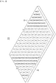
FIG. 1 is a perspective view of a transdermal drug delivery patch according to an exemplary embodiment of the present invention. -
FIG. 2 is a partial enlarged cross-sectional view of a transdermal drug delivery patch shown inFIG. 1 . -
FIG. 3 is an enlarged perspective view of one microneedle of a transdermal drug delivery patch shown inFIG. 1 . -
FIG. 4 is a top plan view of a microneedle shown inFIG. 3 . -
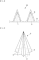
FIG. 5 is a perspective view showing a microneedle made with a quadrangular pyramid shape according to a comparative example. -
FIG. 6 is a perspective view showing microneedles according to exemplary variations that may be implemented. -
FIG. 7 is a process flowchart showing a manufacturing method of a patch according to an exemplary embodiment of the present invention. -
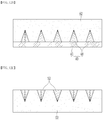
FIG. 8A to FIG. 8D are views showing a master mold manufacturing process of a first step shown inFIG. 7 . -
FIG. 9 to FIG. 11 are views showing a light transmission part shown inFIG. 8A and a protruded part shown inFIG. 8D according to an exemplary variation. -
FIG. 12A to FIG. 12C are views showing a mold manufacturing process of a second step shown inFIG. 7 . -
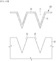
FIG. 13A to FIG. 13D are views showing a patch manufacturing process of a third step shown inFIG. 7 . -
FIG. 14A to FIG. 14C are views showing a patch manufacturing process shown inFIG. 13A to FIG. 13D according to an exemplary variation. -
FIG. 15A andFIG. 15B are views showing a patch manufacturing process shown inFIG. 13A to FIG. 13D according to another exemplary variation. - The present invention will be described more fully hereinafter with reference to the accompanying drawings, in which exemplary embodiments of the invention are shown. As those skilled in the art would realize, the described embodiments may be modified in various different ways, all without departing from the scope of the present invention.
-
FIG. 1 is a perspective view of a transdermal drug delivery patch according to an exemplary embodiment of the present invention, andFIG. 2 is a partial enlarged cross-sectional view of a transdermal drug delivery patch shown inFIG. 1 .FIG. 3 is an enlarged perspective view of one microneedle of a transdermal drug delivery patch shown inFIG. 1 , andFIG. 4 is a top plan view of a microneedle shown inFIG. 3 . - Referring to
FIG. 1 to FIG. 4 , apatch 100 of the present exemplary embodiment is composed of a plurality ofmicroneedles 10 having anempty space 11 therein and abase layer 20 that integrally connects the plurality ofmicroneedles 10 by contacting the plurality ofmicroneedles 10. A plurality ofmicroneedles 10 are aligned on one surface of thebase layer 20 at a distance from each other. - A plurality of
openings 21 may be disposed in thebase layer 20, and eachempty space 11 of a plurality ofmicroneedles 10 may communicate with theopenings 21. That is, theempty space 11 of the microneedle 10 may be an open space toward the rear. Thebase layer 20 is a flexible supporter that supports a plurality ofmicroneedles 10, and may be composed of a biodegradable polymer film having a predetermined thickness that is easily bent to be suitable to the curvature of the skin. - A plurality of
microneedles 10 may have the same size and the same shape and may be aligned side by side on thebase layer 20. The microneedle 10 is made of a biodegradable polymer dispersed with the drug in a powder or liquid form, and penetrates a stratum corneum of the skin and penetrates into an epidermis or dermis of the skin. The drug may be concentrated on the pointed tip of the microneedle 10 or uniformly distributed throughoutmicroneedle 10. - The biodegradable polymer constituting the
patch 100 may include at least one of hyaluronic acid, carboxymethyl cellulose, and polyvinyl alcohol, but is not limited to this example. The microneedle 10 is decomposed by a body fluid while staying in the epidermis or dermis of the skin for several minutes to several hours to absorb the drug into the body. - In the
patch 100 of the present exemplary embodiment, themicroneedle 10 is made as a star-shaped pyramid including a plurality ofprotrusions 12 extending in the radial direction. In the entire specification, 'the radial direction' refers to the direction extending from the center of the microneedle 10 in all directions when viewing the microneedle 10 from the top (i.e., on the plane of the microneedle 10). - In
FIG. 3 andFIG. 4 , the microneedle 10 made as an octagonal star-shaped pyramid is shown as an example. - A plurality of
protrusions 12 extend parallel to the radial direction from the center of the microneedle 10, and the size of theprotrusions 12 gradually decreases as the distance from thebase layer 20 increases. Further, among a plurality ofprotrusions 12, a concave shape is formed between twoadjacent protrusions 12 along the circumferential direction. In the entire specification, 'the circumferential direction' means the direction to surround the microneedle 10 once. - The fact that a plurality of
protrusions 12 extend in the radial direction and the twoprotrusions 12 adjacent along the circumferential direction form the concave shape is an important shape characteristic that distinguishes it from a microneedle having a polygonal pyramid shape such as a quadrangular pyramid. -
FIG. 5 is a perspective view showing a microneedle made with a quadrangular pyramid shape according to a comparative example. Referring toFIG. 5 , the microneedle 30 with the quadrangular pyramid shape has fourcorners 31 when viewed from above, and a straight line is formed between twocorners 31 adjacent to each other among the fourcorners 31. - Again referring to
FIG. 3 andFIG. 4 , in thepatch 100 according to the present exemplary embodiment, when assuming an imaginary line L1 that connects twoprotrusions 12 adjacent along the circumferential direction to a shortest distance among a plurality ofprotrusions 12 included in the microneedle 10, the space between the twoprotrusions 12 is disposed more inward toward the center of the microneedle 10 than this imaginary line L1. - Specifically, each of a plurality of
protrusions 12 is composed of apointed end 13 and aroot portion 14 connected to the neighboringprotrusions 12, and theroot portion 14 is disposed more inward toward the center of the microneedle 10 than the imaginary line that connects two pointed ends 13 adjacent along the circumferential direction with the shortest distance. - Each protruded length of a plurality of
protrusions 12 according to the radial direction may be the same, and a distance between twoend portions 13 adjacent to each other according to the circumferential direction among the plurality ofprotrusions 12 may be the same. That is, the microneedle 10 may achieve rotational symmetry. Themicroneedles 10, which have a rotationally symmetrical shape, may uniformly contact the body fluid on the entire surface to increase the decomposition efficiency of the biodegradable polymer. - The microneedle 10 composed of the star-shaped pyramid has an enlarged surface area and has high mechanical strength by the protruded shape of the
protrusions 12 and the concave shape between theprotrusions 12. In other words, themicroneedle 10 has an enlarged surface area and improved mechanical strength compared to a microneedle of a conical or quadrangular pyramid shape having an empty space of the same height and volume. - When the microneedle 10 is penetrated into the epidermis or dermis of the skin, the wider the surface area, the wider the contact with the body fluids, and the faster the absorption speed of the body fluid. Therefore, the biodegradable polymer that constitutes the microneedle 10 may quickly dissolve and release the drug quickly.
- Meanwhile, the
empty space 11 of the microneedle 10 has the effect of quickly separating thepatch 100 from the skin and shortens the time required to keep thepatch 100 attached to the skin, but it deteriorates the mechanical strength of themicroneedle 10. Themicroneedle 10 of the present exemplary embodiment has improved mechanical strength due to the stable many-sidedness star shape of a plurality ofprotrusions 12 and may easily penetrate the skin and deliver the drug into the body. - The number of the
protrusions 12 constituting the microneedle 10 in thepatch 100 of the present exemplary embodiment is not limited to eight, and may be variously changed. Specifically, the number of theprotrusions 12 constituting the microneedle 10 is 3 or more, and preferably may belong to the range of 3 to 20. - When the number of the
protrusions 12 is 3 or more, the microneedle 10 may implement a star-shaped pyramid. When the number of the protrusions exceeds 20, the manufacturing process of thepatch 100 is complicated, and the surface area enlargement effect is small compared to the cone. -
FIG. 6 is a perspective view showing microneedles according to exemplary variations that may be implemented. InFIG. 6 , the micro-needle 10a with the quadrangle star shape of a pyramid for each square, the micro-needle 10b with the pentagon star shape of a pyramid, and the microneedle 10c with the hexagonal shape of a pyramid are shown as examples. - Again referring to
FIG. 1 to FIG. 4 , thepatch 100 of the present exemplary embodiment may increase the mechanical strength of the microneedle 10 while maintaining a high aspect ratio of the microneedle 10 and effectively enlarge the surface area. As a result, the skin penetration efficiency of the microneedle 10 and the absorption efficiency of the drug may be improved, and the drug may be absorbed into the body in a shorter time. - Next, the manufacturing method of the patch according to the present exemplary embodiment is described.
FIG. 7 is a process flowchart showing a manufacturing method of a patch according to an exemplary embodiment of the present invention. - Referring to
FIG. 7 , the manufacturing method of the patch includes a first step (S10) of manufacturing a master mold including a plurality of protruded parts made as a star-shaped pyramid, a second step (S20) of manufacturing a mold by using the master mold, and a third step (S30) of manufacturing a patch including a plurality of microneedles and a base layer by using the mold. -
FIG. 8A to FIG. 8D are views showing a master mold manufacturing process of a first step shown inFIG. 7 . - Referring to
FIG. 8A to FIG. 8C , aphotocurable polymer layer 42 is disposed on atransparent plate 41 such as a glass plate, and agrayscale mask 44 is disposed between alight source 43 and thetransparent plate 41. Thelight source 43 may be composed of an ultraviolet ray collimated light exposure device, and the photo-curable polymer layer 42 may include an ultraviolet ray curable polymer. - The
grayscale mask 44 is an exposure mask including a plurality of regions having different light transmission rates. In the present exemplary embodiment, thegrayscale mask 44 includes a star-shapedlight transmission part 45 including a plurality of protrusions extending in a radial direction, and alight blocking part 46 other than thelight transmission part 45. - The
light blocking part 46 may be a metal layer that blocks ultraviolet rays, and thelight transmission part 45 may be an opening region from which the metal layer is removed. InFIG. 8A to FIG. 8C , an octagonal star-shapedlight transmission part 45 is illustrated as an example. - In the
grayscale mask 44, thelight transmission part 45 has a light transmission rate that decreases further away from the center. To this end, thelight transmission part 45 may be composed of a plurality of dots, and the plurality of dots may have a smaller size when moving away from the center of the light transmission part 45 (referring toFIG. 8B ). On the other hand, thelight transmission part 45 may be composed of a plurality of dots having the same size, and the distance between the dots may increase as the distance from the center of thelight transmission part 45 increases (referring toFIG. 8C ). - When the
light source 43 is operated and light is irradiated to the photo-curable polymer layer 42 through thegrayscale mask 44, the photo-curable polymer layer 42 at the position corresponding to thelight transmission part 45 is cured by the light. At this time, the shape of the curedstructure 47 corresponds to the planar shape of thelight transmission part 45, and the height of the curedstructure 47 is proportional to the light intensity of thelight source 43 and the light transmission rate of thelight transmission part 45. - As shown when the
grayscale mask 44 has the octagonal star-shapedlight transmission part 45 as shown inFIG. 8B and FIG. 8C , the curedstructure 47 has an octagonal star-shaped pyramid shape that decreases in height as the distance from the center increases. - The photo-
curable polymer layer 42 on thetransparent plate 41 is divided into a cured part and an uncured part, and the uncured part is removed by developing. Then, as shown inFIG, 8D , themaster mold 40 consisting of thetransparent plate 41 and a plurality of protrudedparts 48 arranged on one surface of thetransparent plate 41 is completed. A plurality of protrudedpart 48 consists of an octagonal star-shaped pyramid. -
FIG. 9 to FIG. 11 are views showing a light transmission part shown inFIG. 8A and a protruded part shown inFIG. 8D according to an exemplary variation. - Referring to
FIG. 9 , thelight transmission part 45a includes four protrusions extending in a radial direction and has a light transmission rate that decreases away from the center. Theprotruded part 48a of the master mold manufactured by using thisgrayscale mask 44a is made as a square star-shaped pyramid. - Referring to
FIG. 10 , thelight transmission part 45b includes five protrusions extending in a radial direction and has a light transmission rate that decreases as the distance from the center increases. Theprotruded part 48b of the master mold manufactured by using thisgrayscale mask 44b is made as a pentagonal star-shaped pyramid. - Referring to
FIG. 11 , thelight transmission part 45c includes six protrusions extending in a radial direction and has a light transmission rate that decreases as the distance from the center increases. Theprotruded part 48c of the master mold manufactured by using thisgrayscale mask 44c is made as a hexagonal star-shaped pyramid. -
FIG. 9 to FIG. 11 illustrates thelight transmission parts light transmission parts FIG. 8C . - By changing the shape of the
light transmission part 45 in this way, it is possible to manufacture the star-shaped pyramid protrudedpart 48 having a number of protrusions included in the range of 3 or more, preferably 3 to 20. -
FIG. 12A to FIG. 12C are views showing a mold manufacturing process of a second step shown inFIG. 7 . - Referring to
Fig. 12A to FIG. 12C , a polymer solution is coated on themaster mold 40 to form apolymer layer 51. Thepolymer layer 51 may include a thermosetting resin. Thepolymer layer 51 may include, for example, polydimethylsiloxane, but is not limited to this example. - At this time, since fine bubbles may be disposed around the surface of the
polymer layer 51 in contact with themaster mold 40, a method of applying a negative pressure to thepolymer layer 51 by using a vacuum device (although not shown) may be used to remove the fine bubbles. - Subsequently, heat is applied to the
polymer layer 51 to be cured, and themaster mold 40 is separated from the curedmold 52 to complete themold 52 having a plurality ofrecess portions 53. Themold 52 may have a plate structure with a predetermined thickness, and a plurality ofrecess portions 53 having the shape corresponding to theprotruded part 48 of themaster mold 40 are disposed on one surface of themold 52. - The patch manufacturing process of the third step shown in
FIG. 7 may be accomplished by any of following three methods.FIG. 13A to FIG. 13D show the first method,FIG. 14A to FIG. 14C show the second method, andFIG. 15A and FIG. 15C show the third method. -
FIG. 13A to FIG. 13D are views showing a patch manufacturing process of a third step shown inFIG. 7 . - Referring to
FIG. 13A and FIG. 13B , thedrug 61 is injected to each pointed end portion of a plurality ofrecess portions 53 and abiodegradable polymer solution 62 is thinly coated on the surface of themold 52 between each wall surface of a plurality ofrecess portions 53 so that thebiodegradable polymer solution 62 continues seamlessly along the curvature of themold 52 surface. - That is, the
biodegradable polymer solution 62 is disposed at a predetermined thickness along each wall of a plurality ofrecess portions 53 and is also disposed at a predetermined thickness on the surface of themold 52 between a plurality ofrecess portions 53. The thickness of thebiodegradable polymer solution 62 coated to themold 52 may be less than half of the depth of therecess portion 53, and microbubbles may exist on the surface or inside thedrug 61 and thebiodegradable polymer solution 62. - Referring to
FIG. 13C , avacuum filter 71 and avacuum chamber 72 are disposed on the rear of themold 52. Thevacuum filter 71 is composed of a porous plate in which a plurality of holes are formed, and thevacuum chamber 72 includes an internal space connected to avacuum pump 73. Themold 52 has an ultra-fine porous structure that is hardened but has numerous micropores inside. - When the
vacuum pump 73 is operated, a negative pressure is applied to thedrug 61 and thebiodegradable polymer solution 62 through thevacuum filter 71 and themold 52. The negative pressure at this time is not a pressure applied in all directions and is a pressure in a single direction from thedrug 61 and thebiodegradable polymer solution 62 toward themold 52. - By using the negative pressure in a single direction applied from the back side of the
mold 52, microbubbles contained within thedrug 61 andbiodegradable polymer solution 62 may be easily removed without deforming them. - Referring to
FIG. 13D , thedrug 61 and thebiodegradable polymer solution 62 are dried and hardened into apatch 100 of a solid type, and then thepatch 100 is separated from themold 52. Thepatch 100 is composed of a plurality ofmicroneedles 10 in which the drug is concentrated in a pointed end portion while having anempty space 11 therein and abase layer 20 connecting a plurality ofmicroneedles 10. -
FIG. 14A to FIG. 14C are views showing a patch manufacturing process shown inFIG. 13A to FIG. 13D according to an exemplary variation. - Referring to
FIG. 14A to FIG. 14C , the drug of a powder or liquid form is dispersed into a biodegradable polymer solution to prepare amaterial solution 63, and thematerial solution 63 is coated thinly along each wall of a plurality ofrecess portions 53. The thickness of thecoated material solution 63 may be less than half the depth of therecess portion 53. - Then, the
biodegradable polymer solution 62 is coated to the surface of themold 52 between a plurality ofrecess portions 53. The negative pressure in the single direction is then applied from the back side of themold 52, to thematerial solution 63 and thebiodegradable polymer solution 62 to remove the microbubbles contained in thematerial solution 63 and biodegradable polymer solution 62 (referring toFIG. 13C ). - Subsequently, the
material solution 63 disposed in a plurality ofrecess portions 53 and thebiodegradable polymer solution 62 on the surface of themold 52 are dried and hardened into thepatch 100 of a solid type, and then thepatch 100 is separated from themold 52. - The
patch 100 is composed of a plurality ofmicroneedles 10 in which the drug is uniformly dispersed while having anempty space 11 therein and abase layer 20 connecting a plurality ofmicroneedles 10. -
FIG. 15A andFIG. 15B are views showing a patch manufacturing process shown inFIG. 13A to FIG. 13D according to another exemplary variation. - Referring to
FIG. 15A andFIG. 15B , the drug of a powder or liquid form is dispersed into a biodegradable polymer solution to prepare thematerial solution 63, and thematerial solution 63 is thinly coated on the surface of themold 52 between each wall surface of a plurality ofrecess portions 53 53 so that thematerial solution 63 continues seamlessly along the curvature of the mold surface. The thickness of thecoated material solution 63 may be less than half the depth of therecess portion 53. - And, the microbubbles contained in the
material solution 63 are removed by applying the negative pressure in the single direction to thematerial solution 63 from the back side of the mold 52 (referring toFIG. 13C ). Then, thematerial solution 63 is dried and hardened into thepatch 100 of a solid type, and then thepatch 100 is separated from themold 52. - The
patch 100 is composed of a plurality ofmicroneedles 10 having anempty space 11 therein and abase layer 20 connecting a plurality ofmicroneedles 10, and the plurality ofmicroneedles 10 and thebase layer 20 include the drug that is uniformly dispersed. - According to the above-described method, a plurality of
molds 52 can be mass-produced by manufacturing onemaster mold 40, and thepatch 100 may be easily manufactured by using a plurality ofmolds 52. In addition, it is possible to manufacture a plurality ofmicroneedles 10 having excellent shape precision without air bubbles on the surface or inside. - A plurality of
microneedles 10 included in thepatch 100 are formed of the same star-shaped pyramid as theprotruded part 48 of themaster mold 40 while having theempty space 11 inside. - While this invention has been described in connection with what is presently considered to be practical exemplary embodiments, it is to be understood that the invention is not limited to the disclosed embodiments. On the contrary, it is intended to cover various modifications and equivalent arrangements included within the scope of the appended claims.
Claims (17)
- A transdermal drug delivery patch comprising:a flexible base layer; anda plurality of microneedles disposed at one surface of the base layer, including a biodegradable polymer and a drug, and having an empty space inside,wherein each of the plurality of microneedles is formed of a star-shaped pyramid including a plurality of protrusions extending in a radial direction, anda part between two protrusions adjacent along the circumferential direction among the plurality of protrusions is concave.
- The transdermal drug delivery patch of claim 1, wherein
an opening of each empty space of the plurality of microneedles is formed in the base layer. - The transdermal drug delivery patch of claim 1, wherein
in each of a plurality of microneedles, all protruded lengths of each of the plurality of protrusions according to the radial direction are the same, and all distances between two protrusions adjacent along the circumferential direction among the plurality of protrusions are the same. - The transdermal drug delivery patch of claim 3, wherein
a number of the plurality of protrusions is 3 or more and 20 or less. - The transdermal drug delivery patch of claim 1, wherein
in each of the plurality of microneedles, the drug is concentrated at a pointed end portion of the microneedle. - The transdermal drug delivery patch of claim 1, wherein
in each of the plurality of microneedles, the drug is uniformly distributed on the entire microneedle. - A manufacturing method of a transdermal drug delivery patch, comprising:manufacturing a master mold including a transparent plate and a plurality of protruded parts disposed at one surface of the transparent plate and made of a star-shaped pyramid including a plurality of protrusions extending in a radial direction;manufacturing a mold including a plurality of recess portions having a shape corresponding to a plurality of protruded parts by using the master mold; andmanufacturing a transdermal drug delivery patch including a base layer and a plurality of microneedles having a shape corresponding to a plurality of recess portions while having an empty space inside by using the mold, and a drug and a biodegradable polymer solution.
- The manufacturing method of the transdermal drug delivery patch of claim 7, wherein
the manufacturing of the master mold includes:forming a photo-curable polymer layer on a transparent plate;disposing a grayscale mask between a light source and the transparent plate; andirradiating light to the photo-curable polymer layer through the grayscale mask for a process of curing a part of the photo-curable polymer layer. - The manufacturing method of the transdermal drug delivery patch of claim 8, wherein
the grayscale mask includes a star-shaped light transmission part including a plurality of protrusions extending in a radial direction and a light blocking part other than the light transmission part, and
the light transmission rate of the light transmission part gets is smaller further away from the center of the light transmission part. - The manufacturing method of the transdermal drug delivery patch of claim 9, wherein
the light transmission part is composed of a plurality of dots, and
the plurality of dots have a smaller size further away from the center of the light transmission part. - The manufacturing method of the transdermal drug delivery patch of claim 9, wherein
the light transmission part is composed of a plurality of dots with the same size, and
the further away from the center of the light transmission part, the greater the distance between the plurality of dots. - The manufacturing method of the transdermal drug delivery patch of claim 7, wherein
the manufacturing of the mold includes
coating a polymer solution on the master mold to form a polymer layer; and
applying heat to the polymer layer to be cured. - The manufacturing method of the transdermal drug delivery patch of claim 12, wherein
before curing the polymer layer, a negative pressure is applied to the polymer layer to remove microbubbles included in the polymer layer. - The manufacturing method of the transdermal drug delivery patch of claim 7, wherein
the manufacturing of the transdermal drug delivery patch includes:filling a drug at each pointed end portion of a plurality of recess portions included in the mold;coating a biodegradable polymer solution at the mold surface between each wall surface of a plurality of recess portions and the plurality of recess portions;manufacturing the base layer and a plurality of microneedles by drying the drug and the biodegradable polymer solution; andseparating the base layer and the plurality of microneedles from the mold. - The manufacturing method of the transdermal drug delivery patch of claim 14, wherein
before drying the drug and the biodegradable polymer solution,
a vacuum filter and a vacuum chamber are disposed at the rear of the mold, a vacuum pump connected to the vacuum chamber is operated, and
a negative pressure in a single direction is applied to the drug and the biodegradable polymer solution through the mold and the vacuum filter to remove microbubbles included in the drug and the biodegradable polymer solution. - The manufacturing method of the transdermal drug delivery patch of claim 7, wherein
the manufacturing of the transdermal drug delivery patch includes:coating a material solution in which a biodegradable polymer solution and a drug are mixed to each wall surface of the plurality of recess portions included in the mold;coating the biodegradable polymer solution to the mold surface of the plurality of recess portions;drying the material solution and the biodegradable polymer solution to manufacture the base layer and a plurality of microneedles; andseparating the base layer and the plurality of microneedles from the mold. - The manufacturing method of the transdermal drug delivery patch of claim 16, wherein
before drying the material solution and the biodegradable polymer solution,
a vacuum filter and a vacuum chamber are disposed at the rear of the mold, a vacuum pump connected to the vacuum chamber is operated, and
a negative pressure of a single direction is applied to the material solution and the biodegradable polymer solution through the mold and the vacuum filter to remove microbubbles included in the material solution and the biodegradable polymer solution.
Applications Claiming Priority (1)
| Application Number | Priority Date | Filing Date | Title |
|---|---|---|---|
| PCT/KR2018/005738 WO2019221318A1 (en) | 2018-05-18 | 2018-05-18 | Transdermal drug delivery patch and method for preparing same |
Publications (2)
| Publication Number | Publication Date |
|---|---|
| EP3795206A1 true EP3795206A1 (en) | 2021-03-24 |
| EP3795206A4 EP3795206A4 (en) | 2022-01-05 |
Family
ID=68540575
Family Applications (1)
| Application Number | Title | Priority Date | Filing Date |
|---|---|---|---|
| EP18918983.0A Withdrawn EP3795206A4 (en) | 2018-05-18 | 2018-05-18 | DRUG DIFFUSION TRANSDERMAL STAMP AND PROCESS OF PREPARATION |
Country Status (6)
| Country | Link |
|---|---|
| US (2) | US12036378B2 (en) |
| EP (1) | EP3795206A4 (en) |
| JP (1) | JP2021522978A (en) |
| KR (2) | KR102759984B1 (en) |
| CN (1) | CN112423829B (en) |
| WO (1) | WO2019221318A1 (en) |
Families Citing this family (10)
| Publication number | Priority date | Publication date | Assignee | Title |
|---|---|---|---|---|
| US12121618B2 (en) * | 2018-05-18 | 2024-10-22 | Postech Academy-Industry Foundation | Transdermal drug delivery patch and manufacturing method thereof |
| WO2021146554A1 (en) * | 2020-01-16 | 2021-07-22 | Kansas State University Research Foundation | Microneedle, microcone, and photolithography fabrication methods |
| JP2023529034A (en) * | 2021-05-12 | 2023-07-07 | フェロカ インコーポレーテッド | Microneedle patch, method for producing microneedle patch, and apparatus for producing microneedle patch |
| CN114177512B (en) * | 2021-12-20 | 2024-04-30 | 长春工业大学 | Antibacterial and healing-promoting soluble microneedle patch deposited layer by layer and preparation method thereof |
| CN115006709A (en) * | 2022-04-26 | 2022-09-06 | 广东工业大学 | Bionic microneedle and manufacturing method thereof |
| CN117159901B (en) * | 2022-05-25 | 2026-08-04 | 深圳青澜生物技术有限公司 | Preparation method of microneedle patch, forming die and alignment laminating device |
| CN115445072A (en) * | 2022-08-22 | 2022-12-09 | 清华大学深圳国际研究生院 | Soluble bubble microneedle array layer, soluble bubble roller microneedle and preparation method thereof |
| TWI824724B (en) | 2022-09-16 | 2023-12-01 | 達運精密工業股份有限公司 | Microneedle patch, manufacturing mold thereof, and manufacturing method thereof |
| KR102922531B1 (en) * | 2023-04-26 | 2026-02-04 | 서울과학기술대학교 산학협력단 | Microneedle module and bio patch including the same |
| WO2026111430A1 (en) * | 2024-11-21 | 2026-05-28 | 연세대학교 산학협력단 | Microstructure and method for manufacturing same |
Family Cites Families (28)
| Publication number | Priority date | Publication date | Assignee | Title |
|---|---|---|---|---|
| AU767122B2 (en) * | 1998-06-10 | 2003-10-30 | Georgia Tech Research Corporation | Microneedle devices and methods of manufacture and use thereof |
| JP2004310077A (en) * | 2003-03-25 | 2004-11-04 | Nikon Corp | Microlens manufacturing method, microlens and exposure apparatus |
| JP4572821B2 (en) * | 2005-11-30 | 2010-11-04 | セイコーエプソン株式会社 | Gray scale mask and micro lens manufacturing method |
| GB0600795D0 (en) * | 2006-01-16 | 2006-02-22 | Functional Microstructures Ltd | Method of making microneedles |
| JP4265696B2 (en) | 2006-07-04 | 2009-05-20 | 凸版印刷株式会社 | Manufacturing method of microneedle |
| JP5023671B2 (en) * | 2006-11-22 | 2012-09-12 | 凸版印刷株式会社 | Manufacturing method of needle-shaped body |
| JP2008284318A (en) * | 2007-05-15 | 2008-11-27 | Kosumedei Seiyaku Kk | Fine needle for medication consisting of biological material |
| JP2011072695A (en) | 2009-10-01 | 2011-04-14 | Asti Corp | Method of manufacturing microneedle array and micro-needle array structure |
| JP5937092B2 (en) * | 2010-10-19 | 2016-06-22 | トラスティーズ オブ タフツ カレッジ | Silk fibroin-based microneedle and method for producing the same |
| CN103301092B (en) * | 2012-03-06 | 2014-12-03 | 中国科学院理化技术研究所 | Polymer microneedle array chip and its preparation method and application |
| CA2875227C (en) * | 2012-06-15 | 2021-09-14 | University Of Washington Through Its Center For Commercialization | Microstructure-based wound closure devices |
| WO2014077244A1 (en) | 2012-11-13 | 2014-05-22 | 富士フイルム株式会社 | Transdermal absorption sheet, and manufacturing method for same |
| SG11201600331YA (en) * | 2013-07-16 | 2016-02-26 | 3M Innovative Properties Co | Hollow microneedle with bevel opening |
| CN106061546A (en) * | 2014-02-10 | 2016-10-26 | Lts勒曼治疗系统股份公司 | Microneedle system and method for the production thereof |
| JP6207459B2 (en) * | 2014-05-15 | 2017-10-04 | 富士フイルム株式会社 | Method for producing transdermal absorption sheet |
| CN104117137B (en) * | 2014-07-08 | 2017-12-15 | 清华大学 | Unloaded medicine microneedle array and preparation method thereof in a kind of capsule-type |
| KR101549086B1 (en) | 2014-11-10 | 2015-09-02 | 주식회사 스몰랩 | Micro-needle and micro-needle patch |
| JP6317690B2 (en) * | 2015-03-03 | 2018-04-25 | 富士フイルム株式会社 | Transdermal absorption sheet and method for producing the same |
| MA41818A (en) * | 2015-03-27 | 2018-01-30 | Leo Pharma As | MICRO-NEEDLE STAMP FOR ADMINISTRATION OF AN ACTIVE SUBSTANCE TO THE SKIN |
| CN204767021U (en) | 2015-05-07 | 2015-11-18 | 苏州大学 | Hollow silk fibroin microneedle structure |
| EP3351287A4 (en) * | 2015-09-17 | 2019-10-09 | AOF Pte. Ltd. | Micro-needle |
| CN105833424A (en) | 2016-03-21 | 2016-08-10 | 南通纺织丝绸产业技术研究院 | Silk fibroin micro-needle patch and preparation method thereof |
| KR101728526B1 (en) | 2016-06-23 | 2017-04-19 | 주식회사 쿼드메디슨 | Micro-needles and methof of mamufacture |
| KR101692266B1 (en) | 2016-08-01 | 2017-01-03 | 부산대학교 산학협력단 | Microneedle patch and manufacturing method of the microneedle patch |
| KR101852910B1 (en) * | 2016-09-20 | 2018-04-30 | 한국기계연구원 | Fabrication Method of Mold for Microneedle |
| KR101868872B1 (en) | 2016-10-28 | 2018-06-19 | 권영덕 | Micro-needle and manufacturing method thereof |
| JP6304431B2 (en) * | 2017-06-01 | 2018-04-04 | 大日本印刷株式会社 | Microneedle device |
| JP7204748B2 (en) * | 2017-10-16 | 2023-01-16 | トラスティーズ オブ タフツ カレッジ | Systems and methods for making microneedles |
-
2018
- 2018-05-18 CN CN201880095737.2A patent/CN112423829B/en active Active
- 2018-05-18 US US17/055,653 patent/US12036378B2/en active Active
- 2018-05-18 KR KR1020237026059A patent/KR102759984B1/en active Active
- 2018-05-18 JP JP2021514258A patent/JP2021522978A/en active Pending
- 2018-05-18 KR KR1020207036655A patent/KR102604754B1/en active Active
- 2018-05-18 WO PCT/KR2018/005738 patent/WO2019221318A1/en not_active Ceased
- 2018-05-18 EP EP18918983.0A patent/EP3795206A4/en not_active Withdrawn
-
2024
- 2024-06-11 US US18/739,540 patent/US20240325702A1/en active Pending
Also Published As
| Publication number | Publication date |
|---|---|
| US20240325702A1 (en) | 2024-10-03 |
| KR102604754B1 (en) | 2023-11-22 |
| KR20230117261A (en) | 2023-08-07 |
| CN112423829B (en) | 2023-03-28 |
| US20210228854A1 (en) | 2021-07-29 |
| WO2019221318A1 (en) | 2019-11-21 |
| US12036378B2 (en) | 2024-07-16 |
| KR20210006994A (en) | 2021-01-19 |
| JP2021522978A (en) | 2021-09-02 |
| CN112423829A (en) | 2021-02-26 |
| EP3795206A4 (en) | 2022-01-05 |
| KR102759984B1 (en) | 2025-01-24 |
Similar Documents
| Publication | Publication Date | Title |
|---|---|---|
| US20240325702A1 (en) | Transdermal drug delivery patch and manufacturing method thereof | |
| US12121618B2 (en) | Transdermal drug delivery patch and manufacturing method thereof | |
| CA2728400C (en) | Method of manufacturing solid solution peforator patches and uses thereof | |
| JP6481613B2 (en) | Microneedle and method for manufacturing microneedle | |
| KR20170061042A (en) | Micro-Needle, Mold for Producing the Same and Method for Producing the Same | |
| JP6565906B2 (en) | Needle-like body manufacturing method and needle-like body | |
| US20240091515A1 (en) | Microneedle patch, manufacturing mold therefor, and manufacturing method therefor | |
| JP2011142968A (en) | Method of manufacturing microneedle and microneedle substrate | |
| JP4888011B2 (en) | Needle-like body and manufacturing method thereof | |
| JP6476799B2 (en) | Method of manufacturing needle-like body | |
| JP2015023990A (en) | Microneedle sheet manufacturing method and microneedle sheet | |
| CN113226432B (en) | Hollow microneedle for transdermal delivery of active molecules and/or for sampling biological fluids and method for manufacturing such hollow microneedle | |
| JP2014018507A (en) | Method of manufacturing needle-shaped body and needle-shaped body | |
| JP6809013B2 (en) | Transdermal administration device | |
| KR20190099612A (en) | Micro needle array and process for making the same | |
| JP6268733B2 (en) | Manufacturing method of needle-shaped body | |
| KR20190121923A (en) | Manufacturing method for micro-needle using single sapphire template and micro-needle manufactured using the method | |
| JP2014188329A (en) | Method for manufacturing needle-like body | |
| KR20190084422A (en) | Micro needle patch |
Legal Events
| Date | Code | Title | Description |
|---|---|---|---|
| STAA | Information on the status of an ep patent application or granted ep patent |
Free format text: STATUS: THE INTERNATIONAL PUBLICATION HAS BEEN MADE |
|
| PUAI | Public reference made under article 153(3) epc to a published international application that has entered the european phase |
Free format text: ORIGINAL CODE: 0009012 |
|
| STAA | Information on the status of an ep patent application or granted ep patent |
Free format text: STATUS: REQUEST FOR EXAMINATION WAS MADE |
|
| 17P | Request for examination filed |
Effective date: 20201216 |
|
| AK | Designated contracting states |
Kind code of ref document: A1 Designated state(s): AL AT BE BG CH CY CZ DE DK EE ES FI FR GB GR HR HU IE IS IT LI LT LU LV MC MK MT NL NO PL PT RO RS SE SI SK SM TR |
|
| AX | Request for extension of the european patent |
Extension state: BA ME |
|
| DAV | Request for validation of the european patent (deleted) | ||
| DAX | Request for extension of the european patent (deleted) | ||
| REG | Reference to a national code |
Ref country code: DE Ref legal event code: R079 Free format text: PREVIOUS MAIN CLASS: A61M0037000000 Ipc: B29C0033380000 |
|
| A4 | Supplementary search report drawn up and despatched |
Effective date: 20211208 |
|
| RIC1 | Information provided on ipc code assigned before grant |
Ipc: B29C 39/42 20060101ALI20211202BHEP Ipc: B29C 39/02 20060101ALI20211202BHEP Ipc: B29L 31/00 20060101ALI20211202BHEP Ipc: B29C 41/10 20060101ALI20211202BHEP Ipc: B29C 35/08 20060101ALI20211202BHEP Ipc: A61K 9/00 20060101ALI20211202BHEP Ipc: A61K 9/70 20060101ALI20211202BHEP Ipc: A61M 37/00 20060101ALI20211202BHEP Ipc: B29C 33/38 20060101AFI20211202BHEP |
|
| RIN1 | Information on inventor provided before grant (corrected) |
Inventor name: WOO, HYEONSU Inventor name: CHOI, BYOUNGSUN Inventor name: LEE, JUNGHO Inventor name: LIM, GEUNBAE |
|
| STAA | Information on the status of an ep patent application or granted ep patent |
Free format text: STATUS: EXAMINATION IS IN PROGRESS |
|
| 17Q | First examination report despatched |
Effective date: 20241115 |
|
| STAA | Information on the status of an ep patent application or granted ep patent |
Free format text: STATUS: THE APPLICATION IS DEEMED TO BE WITHDRAWN |
|
| 18D | Application deemed to be withdrawn |
Effective date: 20250516 |