EP3795112B1 - Système et procédé pour un protocole et un étalonnage de balayage intra-oral perfectionnés - Google Patents
Système et procédé pour un protocole et un étalonnage de balayage intra-oral perfectionnés Download PDFInfo
- Publication number
- EP3795112B1 EP3795112B1 EP19196496.4A EP19196496A EP3795112B1 EP 3795112 B1 EP3795112 B1 EP 3795112B1 EP 19196496 A EP19196496 A EP 19196496A EP 3795112 B1 EP3795112 B1 EP 3795112B1
- Authority
- EP
- European Patent Office
- Prior art keywords
- area
- arch
- scan
- segments
- dataset
- Prior art date
- Legal status (The legal status is an assumption and is not a legal conclusion. Google has not performed a legal analysis and makes no representation as to the accuracy of the status listed.)
- Active
Links
Images



Classifications
-
- A—HUMAN NECESSITIES
- A61—MEDICAL OR VETERINARY SCIENCE; HYGIENE
- A61C—DENTISTRY; APPARATUS OR METHODS FOR ORAL OR DENTAL HYGIENE
- A61C9/00—Impression cups, i.e. impression trays; Impression methods
- A61C9/004—Means or methods for taking digitized impressions
- A61C9/0046—Data acquisition means or methods
- A61C9/0053—Optical means or methods, e.g. scanning the teeth by a laser or light beam
-
- A—HUMAN NECESSITIES
- A61—MEDICAL OR VETERINARY SCIENCE; HYGIENE
- A61B—DIAGNOSIS; SURGERY; IDENTIFICATION
- A61B1/00—Instruments for performing medical examinations of the interior of cavities or tubes of the body by visual or photographical inspection, e.g. endoscopes; Illuminating arrangements therefor
- A61B1/04—Instruments for performing medical examinations of the interior of cavities or tubes of the body by visual or photographical inspection, e.g. endoscopes; Illuminating arrangements therefor combined with photographic or television appliances
- A61B1/045—Control thereof
-
- A—HUMAN NECESSITIES
- A61—MEDICAL OR VETERINARY SCIENCE; HYGIENE
- A61B—DIAGNOSIS; SURGERY; IDENTIFICATION
- A61B1/00—Instruments for performing medical examinations of the interior of cavities or tubes of the body by visual or photographical inspection, e.g. endoscopes; Illuminating arrangements therefor
- A61B1/24—Instruments for performing medical examinations of the interior of cavities or tubes of the body by visual or photographical inspection, e.g. endoscopes; Illuminating arrangements therefor for the mouth, i.e. stomatoscopes, e.g. with tongue depressors; Instruments for opening or keeping open the mouth
-
- A—HUMAN NECESSITIES
- A61—MEDICAL OR VETERINARY SCIENCE; HYGIENE
- A61B—DIAGNOSIS; SURGERY; IDENTIFICATION
- A61B6/00—Apparatus or devices for radiation diagnosis; Apparatus or devices for radiation diagnosis combined with radiation therapy equipment
- A61B6/02—Arrangements for diagnosis sequentially in different planes; Stereoscopic radiation diagnosis
- A61B6/03—Computed tomography [CT]
- A61B6/032—Transmission computed tomography [CT]
-
- A—HUMAN NECESSITIES
- A61—MEDICAL OR VETERINARY SCIENCE; HYGIENE
- A61B—DIAGNOSIS; SURGERY; IDENTIFICATION
- A61B6/00—Apparatus or devices for radiation diagnosis; Apparatus or devices for radiation diagnosis combined with radiation therapy equipment
- A61B6/50—Apparatus or devices for radiation diagnosis; Apparatus or devices for radiation diagnosis combined with radiation therapy equipment specially adapted for specific body parts; specially adapted for specific clinical applications
- A61B6/51—Apparatus or devices for radiation diagnosis; Apparatus or devices for radiation diagnosis combined with radiation therapy equipment specially adapted for specific body parts; specially adapted for specific clinical applications for dentistry
-
- A—HUMAN NECESSITIES
- A61—MEDICAL OR VETERINARY SCIENCE; HYGIENE
- A61B—DIAGNOSIS; SURGERY; IDENTIFICATION
- A61B6/00—Apparatus or devices for radiation diagnosis; Apparatus or devices for radiation diagnosis combined with radiation therapy equipment
- A61B6/50—Apparatus or devices for radiation diagnosis; Apparatus or devices for radiation diagnosis combined with radiation therapy equipment specially adapted for specific body parts; specially adapted for specific clinical applications
- A61B6/51—Apparatus or devices for radiation diagnosis; Apparatus or devices for radiation diagnosis combined with radiation therapy equipment specially adapted for specific body parts; specially adapted for specific clinical applications for dentistry
- A61B6/512—Intraoral means
-
- A—HUMAN NECESSITIES
- A61—MEDICAL OR VETERINARY SCIENCE; HYGIENE
- A61B—DIAGNOSIS; SURGERY; IDENTIFICATION
- A61B6/00—Apparatus or devices for radiation diagnosis; Apparatus or devices for radiation diagnosis combined with radiation therapy equipment
- A61B6/58—Testing, adjusting or calibrating thereof
- A61B6/586—Detection of faults or malfunction of the device
-
- A—HUMAN NECESSITIES
- A61—MEDICAL OR VETERINARY SCIENCE; HYGIENE
- A61C—DENTISTRY; APPARATUS OR METHODS FOR ORAL OR DENTAL HYGIENE
- A61C8/00—Means to be fixed to the jaw-bone for consolidating natural teeth or for fixing dental prostheses thereon; Dental implants; Implanting tools
- A61C8/0001—Impression means for implants, e.g. impression coping
-
- A—HUMAN NECESSITIES
- A61—MEDICAL OR VETERINARY SCIENCE; HYGIENE
- A61B—DIAGNOSIS; SURGERY; IDENTIFICATION
- A61B90/00—Instruments, implements or accessories specially adapted for surgery or diagnosis and not covered by any of the groups A61B1/00 - A61B50/00, e.g. for luxation treatment or for protecting wound edges
- A61B90/36—Image-producing devices or illumination devices not otherwise provided for
- A61B2090/363—Use of fiducial points
-
- A—HUMAN NECESSITIES
- A61—MEDICAL OR VETERINARY SCIENCE; HYGIENE
- A61B—DIAGNOSIS; SURGERY; IDENTIFICATION
- A61B2576/00—Medical imaging apparatus involving image processing or analysis
-
- G—PHYSICS
- G06—COMPUTING OR CALCULATING; COUNTING
- G06T—IMAGE DATA PROCESSING OR GENERATION, IN GENERAL
- G06T15/00—Three-dimensional [3D] image rendering
- G06T15/005—General purpose rendering architectures
-
- G—PHYSICS
- G06—COMPUTING OR CALCULATING; COUNTING
- G06T—IMAGE DATA PROCESSING OR GENERATION, IN GENERAL
- G06T17/00—Three-dimensional [3D] modelling for computer graphics
-
- G—PHYSICS
- G06—COMPUTING OR CALCULATING; COUNTING
- G06T—IMAGE DATA PROCESSING OR GENERATION, IN GENERAL
- G06T2207/00—Indexing scheme for image analysis or image enhancement
- G06T2207/30—Subject of image; Context of image processing
- G06T2207/30004—Biomedical image processing
- G06T2207/30036—Dental; Teeth
Definitions
- This disclosure relates to dental restoration techniques and specifically for obtaining accurate intra-oral scan results for the connecting areas between segments of an arch.
- Restorations in the form of dental prosthetics may be necessary to address partially or wholly edentulous conditions.
- Traditionally such restorations have been performed by forming a model by providing an impression of the affected areas of a patient's mouth, developing a stone model from the impression, and fabricating a customized prosthetic device on the stone model. The process is cumbersome and requires excessive intrusion into the patient's mouth.
- the stone model provides enough accuracy to produce prosthetics that minimize stress and interference with the edentulous area.
- IOS intra-oral scanning
- a handheld scanner having optical sensors to capture a three-dimensional dataset of the area of interest.
- the resulting dataset may be used for constructing a model for preparing patient specific prosthetics.
- An example of using such datasets to construct a model may be found in U.S. Patent Publication No. 2011-0183289, filed on December 7. 2007 , titled "Method For Manufacturing Dental Implant Components.”
- the IOS process offers a very efficient and cost-effective means by which to acquire and transmit anatomic data for purposes of forming a prosthetic.
- the method known from this document includes using a scan template comprising calibration features on the soft tissue area.
- the connecting area(s) such as the tongue or the roof of the mouth are essentially seen as "oceans" of homogeneous surfaces in the scan dataset in that these homogeneous surfaces are difficult to distinguish from each other because they all appear the same in the scanned dataset.
- FIG. 1A shows a full arch area 100 which includes an arch 102 having a number of teeth 104 on two segments 106 and 108.
- edentulous areas between the teeth 104 on the arch 102 require the application of a dental restoration process.
- a cross-arch geometric connecting area 110 separates the two segments 106 and 108 of the arch 102. In order to form proper restorative devices, such as a bridge for the arch 102 the distance between the two segments 106 and 108 must be accurately determined.
- the connecting geometry area 110 is relatively non-defined (or vague). While a scan of this area eliminates the digital dead space, the quality of the data does not provide for a sufficiently precise digital acquisition and subsequent reconstruction of the dental anatomy of the arch area 100. Such errors are magnified at the end of the segments 106 and 108 due to the geometry of the segments 106 and 108 in relation to the front of the arch 102. For example, a cumulative error of over 180 ⁇ for this posterior cross-arch span connecting area 110 shown in FIG. 1A in a resulting model would be much greater than the tolerance allowed to passively seat a full-arch denture supporting bar framework. While the distortion may be small, the clinical relevance of this error is significant, preventing the proper fabrication of the restorative device.
- FIG. 1B shows a full arch area 150 which includes an arch 152 with a full edentulous condition with two segments 156 and 158.
- edentulous areas on the arch 152 require the application of a dental restoration process.
- a series of implants have already been implanted in the arch 102 in preparation for modeling of the arch area 150.
- Each of the implants 170 has a gingival healing abutment 170 that extends through the soft tissue.
- a cross-arch geometric connecting area 160 separates the two segments 156 and 158 of the arch 152. In order to form proper restorative devices, such as a bridge for the arch 152 the distance between and around the two segments 156 and 158 must be accurately determined.
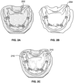
- FIG. 2A shows a control model 202 formed by a 3Shape laser scan of a cast of the arch area 150 and implants 170 shown in FIG. 1B .
- the control model 202 is very accurate since it is prepared by scanning the cast produced from a mold taken from the area of interest. Such a larger scan system is more accurate than the handheld scanners used for the IOS techniques because of the differences in the associated algorithms required for acquiring the data and reconstructing the 3-dimensional datasets.
- FIG. 2B shows a model 204 that is manufactured using a scan dataset from the arch area 150 taken by known IOS techniques. As explained above, the homogeneity of the connecting area 160 results in dimensional inconsistencies between the model 204 and the actual arch area 150.
- FIG. 2C shows the scan model 204 in FIG.
- shaded areas 210 represent distortions between the actual dimensions of the arch area 150 represented by the control model 202 produced by casting and the model 204 produced by known intra-oral scanning techniques. As shown in FIG. 2C , the distortions 210 occur throughout the entire arch, but are greatest on the ends of the segments of the model 204 because of the inaccuracies in determining the dimensions of the connecting geometry between and around the segments. Such inaccuracies may result in positive stretching where the segments of the model are wider than those of the actual arch area. The positive stretching may be seen by the arrows labeled by "EE" in FIG. 2C . The inaccuracies may also result in a model which suffers from negative stretching where the segments are narrower than the actual arch areas. The resulting models therefore are not useful in the restorative process since the resulting prosthesis devices will not interface correctly with the actual arch area.
- One proposed solution has been to spray the connecting geometry area with a coating in order to help establish scannable features within the connecting area.
- the arch and the connecting area are then scanned and a resultant dataset is produced.
- the spraying technique still results in inaccurate scans because the features of the connecting area such as the tongue, assuming that they contain geometry which is distinguishable enough to provide robust data, may move from the location captured during the scan.
- An example of the present disclosure is a method of providing a three-dimensional scan of a dental arch area, the arch area having two segments and a connecting area between the two segments.
- a connecting-geometry tool with at least one definable feature is affixed relative to the dental arch area.
- the at least one definable feature overlays at least part of the connecting area.
- the arch area is scanned to produce a scanned dataset of the arch area.
- Data relating to the definable feature of the connecting-geometry tool overlaying the connecting area is determined based on the scanned dataset.
- the dimensions of the connecting area are determined based on the data relating to the definable feature.
- Another example is a system for producing a scanned dataset of a dental arch area, the dental arch area including two segments and a connecting area between the two segments.
- the system includes a controller and an intra-oral scanner coupled to the controller.
- a connecting-geometry tool affixable to the dental arch area overlays the connecting area.
- the connecting-geometry tool includes at least one definable feature.
- the controller is operative to accept scan data from the intra-oral scanner and determine the dimensions of the connecting area based on data relating to the definable feature.
- a computed tomography scan is performed over the arch area.
- the computed tomography scan includes at least one landmark object in the arch area.
- a reference dimension value of the landmark object is determined in the arch area from the computer tomography scan.
- An intra-oral scan is performed over the arch area including the at least one landmark object and the connecting area.
- a dimension of the landmark object in the arch area is determined from the intra-oral scan.
- the reference dimension value is compared with the dimension of the landmark object determined from the intra-oral scan to determine error correction information.
- the error correction information is applied to the intra-oral scan dataset of the arch area to produce a corrected intra-oral scan dataset.
- the arch area has two segments and a connecting area between the two segments.
- the arch area includes a first implant embedded in the arch area.
- the first implant has a central axis.
- a connecting-geometry tool with at least one definable feature is coupled to the first implant.
- the at least one definable feature is transverse to the central axis of the implant.
- the at least one definable feature overlays at least part of the connecting area.
- the arch area is scanned to produce a scanned dataset of the arch area. Data relating to the definable feature of the connecting-geometry tool overlaying the connecting area is determined based on the scanned dataset.
- the dimensions of the connecting area are determined based on the data relating to the definable feature.
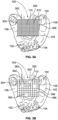
- FIG. 3A is a top view of the arch area 100 shown in FIG. 1A with an affixed connecting-geometry tool 300 to improve the accuracy of a full arch area intra-oral scan.
- the arch area 100 includes the arch 102 which includes teeth 104 and edentulous areas requiring restoration.
- the connecting area 110 is disposed between the segments 106 and 108 which form the arch 102.
- a restorative process may involve the creation of a model of the arch area 100 which may then be used for fabrication of restorative devices such as a dental bridge matching the features of the arch area 100.
- the exemplary dental bridge would be supported by restorative components, such as implants and abutments that may be inserted in the edentulous areas of the arch 102.
- restorative processes may address smaller segments of the arch such as partial segments with more high edentulous areas.
- the model of the dental arch area 100 may be created by the use of a dataset obtained from three-dimensional intra-oral scanning.
- intra-oral scanning involves a handheld three-dimensional intra-oral scanner that may be used to scan the arch area 100 to produce the dataset.
- An example three-dimensional intra-oral scanner may include two stereo cameras that capture image data from an area of interest such as an individual tooth or the entire arch area 100.
- Exemplary intra-oral scanner systems may include but not be limited to the 3M Lava C.O.S., the Cadent iTero digital impression system, and the Sirona CEREC intraoral scanner.
- Corresponding software captures all images from the scanner in real-time, generates a three-dimensional model of the area of interest, and sends the dataset to a computer.
- the resulting dataset may be used to fabricate models of the arch area 100 for preparation of restoration devices. Since the dimensions of the arch area 100 are necessary to produce a model for the entire arch area 100, the scanned dataset includes images of the connecting area 110.
- the digital dead space represented by the connecting area 110 may be covered with a "connecting-geometry" tool having scannable or definable features to bridge the gap between the open segments 106 and 108 of the arch 102.
- the connecting-geometry tool is temporarily affixed to the area of interest such as the arch 102 and extends over the connecting area 110.
- the connecting-geometry tool ideally contains distinct features that register in the scan dataset produced when scanning the connecting area 110.
- the resulting scanned dataset therefore includes more accurate scans of both the arch 102 and the connecting area 110 with the connecting-geometry tool because of the inclusion of scannable or definable features overlaying the connecting area 110.
- a connecting-geometry tool is a homogeneous mesh grid 300 shown in FIG. 3A .
- the mesh grid 300 is anchored on one or both of the segments 106 and 108 of the arch 102 prior to scanning the arch area 100. This may be done by an adhesive such as a dental acrylic applied to the segments 106 and 108 and the mesh grid 300 or by a mechanical device such as a pin or pins attaching the segments 106 and 108 to the mesh grid 300.
- the mesh grid 300 may be coupled to those implants, either directly or indirectly, through components such as healing abutments attached to the implants as will be explained below.
- the mesh grid 300 in this example is fabricated using metal and includes a frame 302 having two side rails 304 and 306. As explained above, the side rails 304 and 306 are preferably affixed to the segments 106 and 108 during the scanning procedure.
- the mesh grid 300 includes uniform squares 310 which are of a set dimension. The dimensions of the squares 310 are selected based on scanner resolution to define the connecting geometry area 110 and in this example are 2 mm square. Of course other materials such as polymers may be used for the mesh 300. Further, other dimensions may be selected for the size of the squares 310. Finally, other shapes such as triangles, polygons, etc. may be used instead of the squares 310.
- a scan may be taken of the arch 102 and the connecting geometry area 110.
- the features of the arch area 100 such as the teeth 104 provide distinct features and, thus, accurate dimensions may be obtained by the resulting scan dataset of the arch 102. Since the mesh grid 300 overlays the connecting geometry area 110, the separation between the segments 106 and 108 is also well defined and the scan of the connecting geometry area 110 discerns distinct features of the grid 300.
- Data relating to the definable features of the connecting-geometry tool such as the mesh grid 300 on the connecting area 110 is determined based on the scanned dataset.
- the dimensions of the connecting area 110 are determined based on the data relating to the definable features and thereby provides accurate dimensions of the connecting geometry area 110.
- the resulting dataset may be used to create an accurate model of the arch 102 and the connecting geometry area 110 for implant installation and/or restoration processes.
- FIG. 3B shows another type of a connecting-geometry tool which is a heterogeneous mesh grid 350 that is affixed to the arch 102 in FIG. 1A prior to scanning the arch area 100.
- the mesh grid 350 in FIG. 3B contains heterogeneous features of known dimensions and distances to provide recognition in the scanned dataset and provide dimensional data for error assessment.
- the mesh grid 350 in this example is fabricated in wire and includes a frame 352 having two side rails 354 and 356.
- the mesh grid 350 includes a grid structure 360 with a number of shapes in the grid structure 360 such as a first square 362, a second square 364 and a rectangle 366.
- the square 362 has a dimension of 4 x 4 mm
- the square 364 has a dimension of 1.5 x 1.5 mm
- the rectangle 366 has a dimension of 1 x 2 mm.
- the distances between the shapes 362, 364 and 366 are also selected to assist in the analysis of the scan dataset.
- the heterogeneous grid shapes of the mesh grid 350 provide better references because of the distinct nature of each of the grid shapes and the known dimensions between them.
- the use of the known dimensions of the shapes in the grid structure 360 may be compared with the dimensions obtained from the scan dataset of these shapes and an error correction factor may be determined based on the difference of the scanned dimensions and the known actual dimensions.
- the scanned dataset may therefore be corrected based on the error correction factor to produce a corrected intra-oral scan dataset.
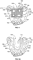
- FIG. 4 shows another type of a connecting-geometry tool to improve the accuracy of full arch scans.
- the connecting-geometry tool in FIG. 4 is a mesh grid 400 that may be inserted in the arch area 100 in FIG. 1A .
- the mesh grid 400 in this example is fabricated in metal and includes a frame 402 having two side rails 404 and 406. As explained above, the mesh arch 400 is affixed to the arch 102.
- the mesh 400 includes uniform squares 410 which are of a set dimension and are composed in a grid. The uniform squares 410 provide distinguishable features when overlaying the connecting geometry area 110. Further features are attached to points in the grid and may include objects 412, 414, 416 and 418 that are included to provide distinct dimensional features to the mesh grid 400.
- the objects can include a cylindrical shape such as object 412, a square shape such as object 414, a rectangular shape such as object 416 and a hexagonal shape such as object 418.
- the objects 412, 414, 416 and 418 form a library of features with known dimensions for reference to the features obtained from the scanned dataset.
- the mesh 400 includes objects such as the objects 412, 414, 416 and 418 of known dimensions (and preferably with known distances relative to each other).
- the mesh 400 is overlaid on the connecting geometry area 110 in the arch area 100.
- the mesh 400 and objects 412, 414, 416 and 418 create identifiable features overlaying the connecting geometry area 110.
- the known dimensions may include the diameter of the circle object 412, the length and width of the square and rectangle objects 414 and 416, and the side lengths and height of the hexagon object 418.
- An error (or distortion) assessment may then be executed to determine the skew in the scan data by assessing the intra-oral scan interpretation of the known dimensions of the objects in comparison with the actual dimensions of the objects.
- the output of this error assessment allows for correction of the entire scan dataset (including features of the arch area 100 and connecting geometry area 110).
- This technique is analogous to scanning both the patient and a calibration object simultaneously, and then error correcting the scan dataset based on the interpretation of the dimensions determined from the scan of the calibration object(s).
- An improved error correction process may be employed with the inclusion of objects with known dimensions in the connecting geometry area 110 such as the objects 412, 414, 416 and 418. Since the dimensions of the objects 412, 414, 416 and 418 on the mesh 400 are known, the scanned dimensions of such objects may be analyzed in real-time during the scan for purposes of correcting any error between the scanned dimensions of all the objects scanned in the arch area 100 and the actual dimensions of the scanned objects. The correction for any deviation may be input into the resulting subsequent data from the scanner output to correct data from the scans of the other features of the arch area 100.
- Such error correction may be performed in real-time as the scan data is being captured and is feasible so long as a portion of the connecting area 110 with a corresponding object of known dimensions such as any or all of the objects 412, 414, 416 and 418, is in view of the scanner throughout the scan acquisition procedure.
- CT scans are based on x-ray technology and may be made for any purpose such as for surgical planning.
- the CT scan of the arch area 110 will capture landmark objects such as the bone and teeth in the arch area 100 but no soft tissue due to the nature of the CT scanning process.
- a subsequent intra-oral scan will pick up the teeth and tissue in arch area 100 but is subject to distortion in the homogeneous connecting area 110 as explained above.
- the results of the CT scan may be analyzed and compared to the dataset from the intra-oral scan to error correct the intra-oral scan dataset.
- the full arch intra-oral scan may be corrected by virtually realigning the teeth 104 (or other robust geometry) in this secondary scan to match the more accurate initial CT scan.
- This removes the skew in the full arch intra-oral scan without having to scan the arch area 100 with a connecting-geometry tool overlaying the connecting area 110.
- the error correction may be made to the intra-oral scan dataset based on the comparison of the reference dimensions of the landmark objects obtained from the CT scan and the dimensions obtained from the intra-oral scan of the landmark objects.
- the resulting error correction may be applied to the intra-oral scan dataset of the arch area to produce a corrected intra-oral scan dataset.
- not all teeth or other geometries need to be present in both scans to provide sufficient error correction.
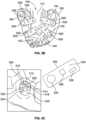
- FIG. 5A shows the arch area 100 in FIG. 1A where healing abutments 500 have been attached to implants (not shown) sunk into the jaw of the arch 102 for purposes of preparing the arch 102 for permanent restoration.
- the healing abutments 500 provide a known geometry for the gingiva above the implant.
- the healing abutments 500 are coded healing abutments that include information about the dimensions and locations of the abutments and underlying implants as shown in U.S. Patent No. 6,790,040 , titled "Healing components for use in taking impressions and methods for making the same,"
- FIG. 5B shows specialized scan plates 502 that are attached to the healing abutments 500 prior to scanning the arch area 100.
- the scan plates 502 may be extended into the connecting geometry area 110 and be used as a connecting-geometry tool on the arch area 100 in FIG. 1A . Since the scan plates 502 have distinct features, the scan dataset of the connecting area 110 provides more accurate geometrical dimensions.
- FIG. 5C is a close-up view of a healing abutment 500 and a scan plate 502 in FIG. 5B .
- the healing abutment 500 includes a top surface 512 that includes a socket 514 that holds a screw (partially shown) with a screw head 516.
- the screw head 516 includes a socket 518 having interlocking side surfaces for the attachment of a driving device to tighten the screw to hold the abutment 500 in the implant embedded in the arch 102.
- the top surface 512 of the healing abutment 500 includes one or more coded features 520 that indicate known dimensional measurements and location of the healing abutment 500 and the underlying implant.
- a sidewall 522 extends from the abutment 500 and includes a dimple feature 524 that serves to support and orient the scan plate 502.
- the scan plate 502 includes a hole 530 that is the same diameter as the abutment 500.
- the scan plate 502 is connected to the abutment 500 via the sidewall 522 and rests on the dimple 524 thereby fixing the scan plate 502 in place relative to the connecting area 110.
- the hole 530 may include a detent that matches the dimple 524 to assist in fixing the scan plate 502 in place.
- the scan plates 502 may include a mating post in place of the hole 530. The mating post may be locked into the socket 518 in the screw head 516 to provide a snap-in attachment of the scan plate 502. There are other ways to connect the connecting-geometry tool to the healing abutment 500.
- the scan plate 502 includes a top surface 534 that has protruding objects 536 and 538 of known dimensions. Since the scan plates 502 extend into the connecting geometry area 110, the intra-oral scan may be made to detect the distinct features of the scan plates 502 such as the objects 536 and 538 or the general shape of the scan plate 502, itself. Alternatively, the portion of the scan plate may be supports for mesh structures to be extended into the connecting geometry area 110.
- a clinician attaches the scan plates 502 to the healing abutments 500 in the arch area 100 prior to scan process.
- the scan plates 502 do not have to fill the entire connecting geometry area 110, but for optimal scanning portions of at least two scan plates 502 should be captured within each IOS digital scan frame.
- the scanning process of the arch 102 and the connecting area 110 with the overlaying scan plates 502 may then be commenced.
- error correction may be performed in real-time by comparing the known dimensions with those dimensions obtained when the objects are determined from the scanned dataset.
- the resulting scanned dataset may be error corrected in real-time.
- an initial scan may be taken of the arch area 100 without the scan plates 502.
- a second scan may then be taken of the arch area 100 with the scan plates 502 in place.
- the initial scan without the scan plates 502 may then be error corrected using the healing abutments 500 from the second scan as a reference object.
- a connecting-geometry tool may be directly coupled to the implant during the scan process and prior to the attachment of abutments.
- the implant has a central axis that is perpendicular to the surface of the arch 102.
- a connecting-geometry tool mateable to an implant has a support body that is connectable to the implant. For example, if the implant has a threaded socket, the support body of the connecting-geometry tool may be threaded.
- Other alternatives may include a matching member to the shape of the socket or a hexagonal connecting interface.
- the connecting-geometry tool mateable to an implant may include an arm that is transverse to the central axis of the implant. When the connecting-geometry tool is inserted in the implant, the arm is thereby extended over the connecting area similar to the scan plates 502 shown in FIG. 5B . As explained above, the arm provides a feature that when overlaying the connecting area 110 provides more accurate scanning.
- any number of connecting-geometry tools mateable to an implant may be attached to implants to provide scannable features overlaying the connecting area 110 in FIG. 1A . For example, if the implants are embedded in the segments 106 and 108, the corresponding connecting-geometry tools would extend from opposite sides of the arch 102 into the connecting area 110.
- the connecting-geometry tool may have features above the implant (like the markings from U.S. Patent No. 6,790,040 ) that permit the location and orientation of the underlying implant to be discerned, while also having laterally extending portions (mesh, arms, etc.) that connect over the soft tissue of connecting area 110 such as the tongue or palate.
- FIG. 6A shows a mesh 600 similar to the mesh 300 in FIG. 3A which overlays the connecting area 110 in FIG. 1A .
- inserts (not shown) have been inserted in the arch 102.
- Healing abutments 610 have been connected to the inserts embedded in the arch 102 in FIG. 6A in this example.
- Each of the healing abutments 610 has a socket 612 for the attachment of the abutment 610 to other devices during the restoration process.
- specialized pins 614 have been inserted in the respective sockets 612 of the healing abutments 610 as shown in FIG. 6B .
- the pins 614 are in turn attached to the mesh 600 to hold the mesh 600 in place over the connecting area 110 during the scanning process.
- other attachment members that are connected to the imbedded inserts in the arch 102 may be used in place of the healing abutments 610 to hold the mesh 600 in place.
- the operation of the example scan process which may be run on a controller, will now be described with reference to FIGs. 1 and 3-6 in conjunction with the flow diagram shown in FIG. 7 .
- the flow diagram in FIG. 7 is representative of exemplary machine readable instructions for implementing an accurate intra-oral scan.
- the machine readable instructions comprise an algorithm for execution by: (a) a processor, (b) a controller, and/or (c) one or more other suitable processing device(s).
- the algorithm may be embodied in software stored on tangible media such as, for example, a flash memory, a CD-ROM, a floppy disk, a hard drive, a digital video (versatile) disk (DVD), or other memory devices, but persons of ordinary skill in the art will readily appreciate that the entire algorithm and/or parts thereof could alternatively be executed by a device other than a processor and/or embodied in firmware or dedicated hardware in a well-known manner (e.g., it may be implemented by an application specific integrated circuit (ASIC), a programmable logic device (PLD), a field programmable logic device (FPLD), a field programmable gate array (FPGA), discrete logic, etc.).
- ASIC application specific integrated circuit
- PLD programmable logic device
- FPLD field programmable logic device
- FPGA field programmable gate array
- any or all of the components of the process could be implemented by software, hardware, and/or firmware.
- some or all of the machine readable instructions represented by the flowchart of FIG. 7 may be implemented manually.
- the example algorithm is described with reference to the flowchart illustrated in FIG. 7 , persons of ordinary skill in the art will readily appreciate that many other methods of implementing the example machine readable instructions may alternatively be used.
- the order of execution of the blocks may be changed, and/or some of the blocks described may be changed, eliminated, or combined.
- FIG. 7 is a flow diagram of a process to provide an accurate scan of the arch area 100 in FIG. 1A for restoration purposes.
- a connecting-geometry tool such as the mesh 300 in FIG. 3A , the mesh 350 in FIG. 3B , the mesh 400 in FIG. 4 , or the scan plates 502 in FIGs. 5A-5C , is affixed relative to the arch 102 to overlay at least part of the connecting geometry area 110 in FIG. 1A (700).
- the connecting-geometry tool has definable features which may be registered by the scanner.
- the dimensions of known features of the connecting-geometry tool are then input in a scanner controller (702).
- These dimensions may also be previously stored in a library for the specific connecting-geometry tool for convenient access by the scanner controller. For example, if objects such as the objects 412, 414, 416 and 418 in FIG. 4 are overlaying the connecting geometry area 110, the dimensions of the objects are stored in memory for error correction purposes.
- a scan is initiated of the arch area 100 and the connecting geometry area 110 to include at least part of the connecting-geometry tool for each scan frame (704).
- a handheld IOS device is preferably used to capture images of the areas of interest to produce the scanned dataset.
- Data relating to the features of the connecting-geometry tool on the connecting area is determined based on the dataset from the scan (706).
- the dimensions of the captured objects are compared with the recorded inputs of the known dimensions to determine error correction information (708).
- the error correction information (708) is incorporated into data inputs from the scan to produce a corrected scan dataset (710).
- a complete dataset of the arch area and connecting geometry is then output for further processing such as for determining dimensions of the arch area 100 for purposes of model construction (712).
- a determination of the dimensions of features of the arch 102 such as edentulous areas and teeth 104 may be determined from the corrected scan dataset (714).
- the dimensions of the connecting area 110 may be determined based on the data relating to the features of the connecting-geometry tool from the corrected dataset (716).
Landscapes
- Health & Medical Sciences (AREA)
- Life Sciences & Earth Sciences (AREA)
- Engineering & Computer Science (AREA)
- Medical Informatics (AREA)
- Public Health (AREA)
- Animal Behavior & Ethology (AREA)
- General Health & Medical Sciences (AREA)
- Veterinary Medicine (AREA)
- Surgery (AREA)
- Optics & Photonics (AREA)
- Physics & Mathematics (AREA)
- Dentistry (AREA)
- Oral & Maxillofacial Surgery (AREA)
- Pathology (AREA)
- Biomedical Technology (AREA)
- Molecular Biology (AREA)
- Heart & Thoracic Surgery (AREA)
- Nuclear Medicine, Radiotherapy & Molecular Imaging (AREA)
- Biophysics (AREA)
- Radiology & Medical Imaging (AREA)
- High Energy & Nuclear Physics (AREA)
- Epidemiology (AREA)
- Orthopedic Medicine & Surgery (AREA)
- Pulmonology (AREA)
- Theoretical Computer Science (AREA)
- Dental Tools And Instruments Or Auxiliary Dental Instruments (AREA)
- Analysing Materials By The Use Of Radiation (AREA)
Claims (15)
- Procédé de production d'un modèle tridimensionnel d'une zone d'arcade dentaire (102) chez un patient, la zone d'arcade dentaire incluant deux segments (106, 108) séparés par une zone de connexion d'arcade transversale homogène de tissus mous (110) entre les deux segments (106, 108), le procédé comprenant :la réception, au niveau d'un ordinateur, d'un ensemble de données de numérisation d'une partie de la bouche d'un patient incluant les deux segments (106, 108), la zone de connexion d'arcade transversale homogène de tissus mous (110), et un outil de géométrie de connexion (300) avec au moins au moins une caractéristique définissable par rapport à la zone d'arcade dentaire (102), l'au moins une caractéristique définissable recouvrant au moins une partie de la zone de connexion d'arcade transversale homogène de tissus mous (110) ;la détermination des données relatives à l'au moins une caractéristique définissable de l'outil de géométrie de connexion (300) recouvrant la zone de connexion d'arcade transversale homogène de tissus mous (110) sur la base de l'ensemble de données de numérisation de la partie de la bouche du patient ; etla détermination des dimensions de la zone de connexion d'arcade transversale homogène de tissus mous (110) sur la base des données relatives à l'au moins une caractéristique définissable pour construire le modèle.
- Procédé selon la revendication 1, dans lequel l'outil de géométrie de connexion est une grille maillée, la grille maillée incluant une pluralité de formes géométriques.
- Procédé selon la revendication 2, dans lequel les formes géométriques ont au moins deux dimensions différentes.
- Procédé selon la revendication 2, dans lequel la grille maillée inclut au moins un objet ayant des dimensions prédéterminées.
- Procédé selon la revendication 1, dans lequel la détermination des dimensions inclut l'exécution d'une évaluation d'erreur pour déterminer une asymétrie dans l'ensemble de données de numérisation par rapport à une dimension connue de l'au moins une caractéristique définissable et une dimension correspondante de l'au moins une caractéristique définissable déterminée à partir des données relatives à l'au moins une caractéristique définissable.
- Procédé selon la revendication 5, incluant en outre :
la correction de l'ensemble de données de numérisation sur la base de l'évaluation d'erreur pour produire un ensemble de données de numérisation intra-oral corrigé. - Procédé selon la revendication 5, dans lequel la correction d'erreur est effectuée en temps réel.
- Procédé selon la revendication 1, dans lequel la zone d'arcade dentaire inclut au moins un pilier fixé dans la zone d'arcade dentaire et dans lequel l'outil de géométrie de connexion est attaché au pilier et s'étend sur la zone de connexion d'arcade transversale homogène de tissus mous.
- Procédé selon la revendication 8, dans lequel l'outil de géométrie de connexion est une plaque.
- Procédé selon la revendication 9, dans lequel la plaque inclut l'au moins un objet définissable, l'au moins un objet définissable ayant une dimension prédéterminée.
- Système pour produire un modèle tridimensionnel d'une zone d'arcade dentaire (102) chez un patient, la zone d'arcade dentaire incluant deux segments (106, 108) séparés par une zone de connexion d'arcade transversale homogène de tissus mous (110) entre les deux segments, le système comprenant :au moins un processeur ; etau moins un dispositif de stockage comprenant des instructions qui, lorsqu'elles sont exécutées par l'au moins un processeur, configurent l'au moins un processeur pour exécuter des opérations comprenant :la réception, au niveau d'un ordinateur, d'un ensemble de données de numérisation d'une partie de la bouche d'un patient incluant les deux segments, la zone de connexion d'arcade transversale homogène de tissus mous, et un outil de géométrie de connexion (300) avec au moins une caractéristique définissable par rapport à la zone d'arcade dentaire, l'au moins une caractéristique définissable recouvrant au moins une partie de la zone de connexion d'arcade transversale homogène de tissus mous ;la détermination de données (706) relatives à l'au moins une caractéristique définissable de l'outil de géométrie de connexion recouvrant la zone de connexion d'arcade transversale homogène de tissus mous sur la base de l'ensemble de données de numérisation de la partie de la bouche du patient ; etla détermination des dimensions (716) de la zone de connexion d'arcade transversale homogène de tissus mous sur la base des données relatives à l'au moins une caractéristique définissable pour construire le modèle.
- Système selon la revendication 11, dans lequel la détermination des dimensions inclut l'exécution d'une évaluation d'erreur pour déterminer une asymétrie dans l'ensemble de données de numérisation par rapport à une dimension connue de l'au moins une caractéristique définissable et une dimension correspondante de l'au moins une caractéristique définissable déterminée à partir des données relatives à l'au moins une caractéristique définissable.
- Système selon la revendication 12, incluant en outre :
la correction de l'ensemble de données de numérisation sur la base de l'évaluation d'erreur pour produire un ensemble de données de numérisation intra-oral corrigé. - Procédé de réalisation d'une numérisation tridimensionnelle d'une zone d'arcade dentaire chez un patient, la zone d'arcade ayant deux segments : (106, 108) séparés par une zone de connexion d'arcade transversale (110) entre les deux segments, le procédé comprenant :la fixation d'un outil de géométrie de connexion (300) avec au moins une caractéristique définissable relative à la zone d'arcade dentaire, l'au moins une caractéristique définissable recouvrant au moins une partie de la zone de connexion ;la numérisation (704) de la zone d'arcade pour produire un ensemble de données numérisées de la zone d'arcade, ledit ensemble de données de numérisation incluant les deux segments, la zone de connexion d'arcade transversale homogène de tissus mous et l'outil de géométrie de connexion ;la détermination de données (706) relatives à la caractéristique définissable de l'outil de géométrie de connexion recouvrant la zone de connexion sur la base de l'ensemble de données numérisées ;et la détermination (716) des dimensions de la zone de raccordement sur la base des données relatives à la caractéristique définissable.
- Procédé selon la revendication 14, dans lequel l'outil de géométrie de connexion est une grille maillée, la grille maillée comprenant une pluralité de formes géométriques.
Applications Claiming Priority (3)
| Application Number | Priority Date | Filing Date | Title |
|---|---|---|---|
| US201261624623P | 2012-04-16 | 2012-04-16 | |
| PCT/US2013/035923 WO2013158432A1 (fr) | 2012-04-16 | 2013-04-10 | Système et procédé pour un protocole et un étalonnage de balayage intra-oral perfectionnés |
| EP13717940.4A EP2838464B1 (fr) | 2012-04-16 | 2013-04-10 | Système et procédé pour un protocole et un étalonnage de balayage intra-oral perfectionnés |
Related Parent Applications (1)
| Application Number | Title | Priority Date | Filing Date |
|---|---|---|---|
| EP13717940.4A Division EP2838464B1 (fr) | 2012-04-16 | 2013-04-10 | Système et procédé pour un protocole et un étalonnage de balayage intra-oral perfectionnés |
Publications (2)
| Publication Number | Publication Date |
|---|---|
| EP3795112A1 EP3795112A1 (fr) | 2021-03-24 |
| EP3795112B1 true EP3795112B1 (fr) | 2023-07-19 |
Family
ID=48143399
Family Applications (2)
| Application Number | Title | Priority Date | Filing Date |
|---|---|---|---|
| EP13717940.4A Active EP2838464B1 (fr) | 2012-04-16 | 2013-04-10 | Système et procédé pour un protocole et un étalonnage de balayage intra-oral perfectionnés |
| EP19196496.4A Active EP3795112B1 (fr) | 2012-04-16 | 2013-04-10 | Système et procédé pour un protocole et un étalonnage de balayage intra-oral perfectionnés |
Family Applications Before (1)
| Application Number | Title | Priority Date | Filing Date |
|---|---|---|---|
| EP13717940.4A Active EP2838464B1 (fr) | 2012-04-16 | 2013-04-10 | Système et procédé pour un protocole et un étalonnage de balayage intra-oral perfectionnés |
Country Status (7)
| Country | Link |
|---|---|
| US (7) | US9198627B2 (fr) |
| EP (2) | EP2838464B1 (fr) |
| JP (1) | JP6389164B2 (fr) |
| AU (1) | AU2013249682B2 (fr) |
| CA (1) | CA2869222C (fr) |
| ES (2) | ES2747201T3 (fr) |
| WO (1) | WO2013158432A1 (fr) |
Families Citing this family (44)
| Publication number | Priority date | Publication date | Assignee | Title |
|---|---|---|---|---|
| US9198627B2 (en) | 2012-04-16 | 2015-12-01 | Biomet 3i | System and method for improved intra-oral scanning protocol and calibration |
| FI125322B (en) * | 2012-06-11 | 2015-08-31 | Planmeca Oy | Tooth Surface Models |
| US9554880B2 (en) | 2012-10-25 | 2017-01-31 | Zfx Gmbh | Reference member for determining a position of an implant analog |
| US9364299B2 (en) | 2012-11-20 | 2016-06-14 | Gerald M. Marlin | Universal aligning adaptor system and methods |
| US10098714B2 (en) * | 2012-12-19 | 2018-10-16 | Align Technology, Inc. | Apparatus and method for optically scanning an object in registration with a reference pattern |
| US10617489B2 (en) | 2012-12-19 | 2020-04-14 | Align Technology, Inc. | Creating a digital dental model of a patient's teeth using interproximal information |
| WO2014102779A2 (fr) | 2012-12-24 | 2014-07-03 | Dentlytec G.P.L. Ltd | Dispositif et procédé de mesure sub-gingivale |
| US10228452B2 (en) * | 2013-06-07 | 2019-03-12 | Hand Held Products, Inc. | Method of error correction for 3D imaging device |
| EP2878335B1 (fr) | 2013-11-10 | 2018-01-03 | Brainsgate Ltd. | Implant et système d'implantation pour stimulateur neural |
| US10111714B2 (en) * | 2014-01-27 | 2018-10-30 | Align Technology, Inc. | Adhesive objects for improving image registration of intraoral images |
| EP3242627B1 (fr) * | 2015-01-08 | 2019-10-23 | Dentlytec G.P.L. Ltd. | Dispositif pour précision de balayage intrabuccal amélioré |
| WO2016113745A1 (fr) | 2015-01-18 | 2016-07-21 | Dentlytec G.P.L. Ltd | Système, dispositif et procédé d'exploration dentaire intra-orale |
| US12259231B2 (en) | 2015-01-18 | 2025-03-25 | Dentlytec G.P.L. Ltd. | Intraoral scanner |
| WO2016118737A1 (fr) * | 2015-01-22 | 2016-07-28 | Neocis, Inc. | Agencements de guidage interactif et de détection de manipulation pour système robotique chirurgical, et méthode associée |
| US10159542B2 (en) | 2015-05-01 | 2018-12-25 | Dentlytec G.P.L. Ltd. | System, device and methods for dental digital impressions |
| US10271907B2 (en) | 2015-05-13 | 2019-04-30 | Brainsgate Ltd. | Implant and delivery system for neural stimulator |
| JP6366546B2 (ja) * | 2015-07-13 | 2018-08-01 | 株式会社モリタ製作所 | 口腔内三次元計測装置、口腔内三次元計測方法及び口腔内三次元計測結果の表示方法 |
| EP3130885A1 (fr) * | 2015-08-11 | 2017-02-15 | Ivoclar Vivadent AG | Dispositif de balayage, ballonnet pour le fonctionnement d'un dispositif de balayage, procede de fonctionnement d'un dispositif de balayage et programme de commande pour un dispositif de balayage |
| EP3405092A2 (fr) | 2016-01-18 | 2018-11-28 | Dentlytec G.P.L. Ltd. | Scanner intraoral |
| EP3471627B1 (fr) | 2016-06-16 | 2025-12-31 | Ark Surgical Ltd. | Dispositif de confinement de tissu destiné à être utilisé dans des interventions chirurgicales |
| US12285188B2 (en) | 2016-09-10 | 2025-04-29 | Ark Surgical Ltd. | Laparoscopic workspace device |
| WO2018047180A1 (fr) | 2016-09-10 | 2018-03-15 | Ark Surgical Ltd. | Dispositif d'espace de travail laparoscopique |
| WO2019008586A1 (fr) | 2017-07-04 | 2019-01-10 | Dentlytec G.P.L. Ltd | Dispositif dentaire avec sonde |
| US11612461B2 (en) * | 2017-07-04 | 2023-03-28 | Dentlytec G.P.L. Ltd. | Tracked dental measurement device |
| EP3658069B1 (fr) | 2017-07-26 | 2024-06-26 | Dentlytec G.P.L. Ltd. | Scanner intra-buccal |
| JP7374093B2 (ja) * | 2017-12-20 | 2023-11-06 | デンツプライ シロナ インコーポレイテッド | 3d画像の検証用ゲージ |
| WO2019211912A1 (fr) * | 2018-05-02 | 2019-11-07 | OTAWA Naruto | Gabarit de balayage, et procédé et système pour spécifier la position spatiale d'un implant, etc. |
| JP2020058677A (ja) * | 2018-10-12 | 2020-04-16 | 株式会社iSight | 口腔内画像生成方法、口腔内画像生成装置、及びコンピュータプログラム |
| EP3870103B1 (fr) * | 2018-10-23 | 2026-02-11 | Dentlytec G.P.L. Ltd. | Procédé et appareil de vérification de guide chirurgical dentaire |
| US12491058B2 (en) | 2019-01-09 | 2025-12-09 | Dentlytec G.P.L. Ltd. | Dental device with probe and methods associated therewith |
| EP4054470A4 (fr) * | 2019-11-04 | 2023-11-15 | Implant Solutions Pty Ltd | Appareil pour faciliter l'acquisition d'un balayage et d'une procédure de balayage intrabuccal |
| US12076200B2 (en) | 2019-11-12 | 2024-09-03 | Align Technology, Inc. | Digital 3D models of dental arches with accurate arch width |
| CN111714235B (zh) * | 2020-06-12 | 2021-07-20 | 深圳云甲科技有限公司 | 就位方向算法、终端及存储介质 |
| USD1112746S1 (en) | 2020-10-02 | 2026-02-10 | Implant Solutions Pty Ltd | Intraoral scan body |
| AU2021369836B2 (en) * | 2020-10-29 | 2023-07-27 | Russell J. CROCKETT | Dental device and method of use |
| EP4262573B1 (fr) | 2020-12-17 | 2026-04-22 | Ark Surgical Ltd. | Dispositif de confinement de tissu laparoscopique |
| CN117295469A (zh) * | 2021-04-06 | 2023-12-26 | R·J·克罗基特 | 牙科装置及使用方法 |
| EP4324423A1 (fr) * | 2021-04-12 | 2024-02-21 | Dos Santos Redinha, Luís António | Pilier de numérisation et chaîne complémentaire |
| CN113483695B (zh) * | 2021-07-01 | 2024-01-26 | 先临三维科技股份有限公司 | 三维扫描系统、辅助件、处理方法、装置、设备及介质 |
| KR102594603B1 (ko) * | 2021-09-27 | 2023-10-27 | 주식회사 디오 | 치아수복물 제조용 이미지 보정지그 및 이를 이용한 치아수복물 제조용 이미지 보정방법 |
| WO2023126850A1 (fr) * | 2021-12-29 | 2023-07-06 | Lastruttura S.P.A. | Gabarit de balayage modulaire universel pour balayage intra-buccal |
| KR102765879B1 (ko) * | 2022-05-02 | 2025-02-11 | 주식회사바텍 | 엑스선 파노라마 영상 표시 장치 |
| US20240415616A1 (en) * | 2023-06-13 | 2024-12-19 | Jun Hyun Park | Dental Scan Body Having Rectangular Block Shape |
| PL131626U1 (pl) * | 2023-08-25 | 2024-10-07 | Orzełowski Aleksander Pracownia Techniki Dentystycznej Almadent | Wskaźnik pozycji implantu do skanowania wewnątrzustnego |
Family Cites Families (32)
| Publication number | Priority date | Publication date | Assignee | Title |
|---|---|---|---|---|
| US5927982A (en) | 1998-09-29 | 1999-07-27 | Kruger; Bernard M. | Three dimensional guidance system for dental implant insertion |
| US8821158B1 (en) * | 1999-10-14 | 2014-09-02 | Geodigm Corporation | Method and apparatus for matching digital three-dimensional dental models with digital three-dimensional cranio-facial CAT scan records |
| US6790040B2 (en) | 1999-11-10 | 2004-09-14 | Implant Innovations, Inc. | Healing components for use in taking impressions and methods for making the same |
| US6413085B1 (en) | 2001-02-20 | 2002-07-02 | Panadent Corporation | System for improving the appearance of teeth |
| US7077647B2 (en) * | 2002-08-22 | 2006-07-18 | Align Technology, Inc. | Systems and methods for treatment analysis by teeth matching |
| WO2006092800A2 (fr) | 2005-03-03 | 2006-09-08 | Cadent Ltd. | Systeme et procede pour l'exploration d'une cavite intrabuccale |
| US7508919B2 (en) * | 2005-05-06 | 2009-03-24 | Young Matthew D | Diagnostic kit, device, and method of using same |
| US8215957B2 (en) * | 2005-05-12 | 2012-07-10 | Robert Shelton | Dental implant placement locator and method of use |
| US8185224B2 (en) | 2005-06-30 | 2012-05-22 | Biomet 3I, Llc | Method for manufacturing dental implant components |
| GB0514554D0 (en) * | 2005-07-15 | 2005-08-24 | Materialise Nv | Method for (semi-) automatic dental implant planning |
| US8257083B2 (en) | 2005-10-24 | 2012-09-04 | Biomet 3I, Llc | Methods for placing an implant analog in a physical model of the patient's mouth |
| WO2008051129A1 (fr) | 2006-10-27 | 2008-05-02 | Nobel Biocare Services Ag | Porte-empreinte dentaire permettant d'obtenir une empreinte d'une structure dentaire |
| CN101578076B (zh) * | 2007-01-10 | 2013-10-23 | 诺贝尔生物服务公司 | 用于牙设计和制备的方法和系统 |
| US20080292779A1 (en) * | 2007-05-22 | 2008-11-27 | Mercuri Gregory M | Coating of implants with hyaluronic acid solution |
| US8075306B2 (en) * | 2007-06-08 | 2011-12-13 | Align Technology, Inc. | System and method for detecting deviations during the course of an orthodontic treatment to gradually reposition teeth |
| US10342638B2 (en) * | 2007-06-08 | 2019-07-09 | Align Technology, Inc. | Treatment planning and progress tracking systems and methods |
| US8021150B2 (en) * | 2007-09-11 | 2011-09-20 | Roberto Carrillo | Method for dental implant placement |
| US20120088208A1 (en) * | 2007-10-19 | 2012-04-12 | Cagenix Incorporated | Method for Defining a Dental Framework Design Volume |
| US8308481B2 (en) * | 2007-10-19 | 2012-11-13 | Cagenix, Inc. | Dental framework |
| JP5250251B2 (ja) | 2007-12-17 | 2013-07-31 | イマグノーシス株式会社 | 医用撮影用マーカーおよびその活用プログラム |
| JP2011509812A (ja) * | 2008-01-23 | 2011-03-31 | センサブル テクノロジーズ インコーポレイテッド | 触覚的に操作可能な歯科モデリングシステム |
| WO2009119620A1 (fr) * | 2008-03-27 | 2009-10-01 | Takebayashi Akira | Prothèse endovasculaire, procédé de reproduction utilisant cette dernière et procédé de détermination de la position des fils |
| US8199988B2 (en) * | 2008-05-16 | 2012-06-12 | Geodigm Corporation | Method and apparatus for combining 3D dental scans with other 3D data sets |
| EP2387372A1 (fr) * | 2009-01-15 | 2011-11-23 | Medentic S.A. | Porte-empreinte et procédé permettant d'effectuer un relevé de structures, d'agencements ou de formes, en particulier dans la bouche ou le corps humain |
| WO2011091382A1 (fr) * | 2010-01-22 | 2011-07-28 | Precision Through Imaging, Llc | Système et procédé d'implantation dentaire |
| US8244028B2 (en) * | 2010-04-30 | 2012-08-14 | Align Technology, Inc. | Virtual cephalometric imaging |
| US20110275029A1 (en) | 2010-05-10 | 2011-11-10 | Fei Gao | Design method of surgical scan templates and improved treatment planning |
| US8712733B2 (en) * | 2010-09-17 | 2014-04-29 | Biocad Medical, Inc. | Adjusting dental prostheses based on soft tissue |
| EP2654608B1 (fr) * | 2010-12-22 | 2019-06-19 | 3Shape A/S | Modelage d'une superstructure pour une prothèse dentaire |
| US20130249907A1 (en) * | 2011-09-12 | 2013-09-26 | Medical Modeling Inc., a Colorado Corporaiton | Fiducial system to facilitate co-registration and image pixel calibration of multimodal data |
| US20150118638A1 (en) * | 2012-04-05 | 2015-04-30 | Trispera Dental, Inc. | Intraoral Imaging Apparatus |
| US9198627B2 (en) | 2012-04-16 | 2015-12-01 | Biomet 3i | System and method for improved intra-oral scanning protocol and calibration |
-
2013
- 2013-01-16 US US13/742,428 patent/US9198627B2/en active Active
- 2013-04-10 CA CA2869222A patent/CA2869222C/fr active Active
- 2013-04-10 JP JP2015507050A patent/JP6389164B2/ja active Active
- 2013-04-10 EP EP13717940.4A patent/EP2838464B1/fr active Active
- 2013-04-10 AU AU2013249682A patent/AU2013249682B2/en not_active Ceased
- 2013-04-10 ES ES13717940T patent/ES2747201T3/es active Active
- 2013-04-10 ES ES19196496T patent/ES2951783T3/es active Active
- 2013-04-10 EP EP19196496.4A patent/EP3795112B1/fr active Active
- 2013-04-10 WO PCT/US2013/035923 patent/WO2013158432A1/fr not_active Ceased
-
2015
- 2015-10-26 US US14/923,048 patent/US10350036B2/en active Active
-
2019
- 2019-06-12 US US16/439,287 patent/US11026770B2/en active Active
-
2021
- 2021-05-10 US US17/315,893 patent/US11607295B2/en active Active
-
2023
- 2023-02-23 US US18/113,507 patent/US20230301756A1/en active Pending
-
2025
- 2025-01-16 US US19/025,530 patent/US20250169927A1/en active Pending
- 2025-01-16 US US19/025,454 patent/US20250152314A1/en active Pending
Also Published As
| Publication number | Publication date |
|---|---|
| ES2951783T3 (es) | 2023-10-24 |
| US10350036B2 (en) | 2019-07-16 |
| CA2869222C (fr) | 2021-04-06 |
| WO2013158432A1 (fr) | 2013-10-24 |
| AU2013249682A1 (en) | 2014-10-23 |
| US20160051346A1 (en) | 2016-02-25 |
| US9198627B2 (en) | 2015-12-01 |
| JP6389164B2 (ja) | 2018-09-12 |
| EP2838464A1 (fr) | 2015-02-25 |
| US20250169927A1 (en) | 2025-05-29 |
| ES2747201T3 (es) | 2020-03-10 |
| CA2869222A1 (fr) | 2013-10-24 |
| AU2013249682B2 (en) | 2018-07-26 |
| US20210369420A1 (en) | 2021-12-02 |
| US20250152314A1 (en) | 2025-05-15 |
| US20190290407A1 (en) | 2019-09-26 |
| US11026770B2 (en) | 2021-06-08 |
| EP2838464B1 (fr) | 2019-09-11 |
| EP3795112A1 (fr) | 2021-03-24 |
| US11607295B2 (en) | 2023-03-21 |
| US20130273492A1 (en) | 2013-10-17 |
| US20230301756A1 (en) | 2023-09-28 |
| JP2015516856A (ja) | 2015-06-18 |
Similar Documents
| Publication | Publication Date | Title |
|---|---|---|
| US20230301756A1 (en) | System and method for improved intra-oral scanning protocol and calibration | |
| US11779444B2 (en) | Methods and systems for dental procedures | |
| KR101279292B1 (ko) | 3차원 물체의 3차원 화상 정합 | |
| KR102114015B1 (ko) | 맞춤형 치료용 지대치의 가상 설계 | |
| EP3242627B1 (fr) | Dispositif pour précision de balayage intrabuccal amélioré | |
| KR101693911B1 (ko) | 디지털 인상 코핑의 구강 내 스캐닝으로부터 환자의 특정 수복물을 설계 및 제조하는 방법 | |
| US8662890B2 (en) | Method for manufacturing a dental restoration | |
| EP3727189B1 (fr) | Jauge de vérification d'images 3-d | |
| US11419708B2 (en) | Digital denture manufacturing method and manufacturing system, and denture hole guider applied thereto and manufacturing method thereof | |
| US20260108330A1 (en) | System and method for improved intra-oral scanning protocol and calibration |
Legal Events
| Date | Code | Title | Description |
|---|---|---|---|
| PUAI | Public reference made under article 153(3) epc to a published international application that has entered the european phase |
Free format text: ORIGINAL CODE: 0009012 |
|
| STAA | Information on the status of an ep patent application or granted ep patent |
Free format text: STATUS: THE APPLICATION HAS BEEN PUBLISHED |
|
| AC | Divisional application: reference to earlier application |
Ref document number: 2838464 Country of ref document: EP Kind code of ref document: P |
|
| AK | Designated contracting states |
Kind code of ref document: A1 Designated state(s): AL AT BE BG CH CY CZ DE DK EE ES FI FR GB GR HR HU IE IS IT LI LT LU LV MC MK MT NL NO PL PT RO RS SE SI SK SM TR |
|
| STAA | Information on the status of an ep patent application or granted ep patent |
Free format text: STATUS: REQUEST FOR EXAMINATION WAS MADE |
|
| 17P | Request for examination filed |
Effective date: 20210924 |
|
| RBV | Designated contracting states (corrected) |
Designated state(s): AL AT BE BG CH CY CZ DE DK EE ES FI FR GB GR HR HU IE IS IT LI LT LU LV MC MK MT NL NO PL PT RO RS SE SI SK SM TR |
|
| GRAP | Despatch of communication of intention to grant a patent |
Free format text: ORIGINAL CODE: EPIDOSNIGR1 |
|
| STAA | Information on the status of an ep patent application or granted ep patent |
Free format text: STATUS: GRANT OF PATENT IS INTENDED |
|
| INTG | Intention to grant announced |
Effective date: 20230130 |
|
| RIN1 | Information on inventor provided before grant (corrected) |
Inventor name: CRUZ, JOELL Inventor name: SUTTIN, ZACHARY B. |
|
| GRAS | Grant fee paid |
Free format text: ORIGINAL CODE: EPIDOSNIGR3 |
|
| GRAA | (expected) grant |
Free format text: ORIGINAL CODE: 0009210 |
|
| STAA | Information on the status of an ep patent application or granted ep patent |
Free format text: STATUS: THE PATENT HAS BEEN GRANTED |
|
| P01 | Opt-out of the competence of the unified patent court (upc) registered |
Effective date: 20230526 |
|
| AC | Divisional application: reference to earlier application |
Ref document number: 2838464 Country of ref document: EP Kind code of ref document: P |
|
| AK | Designated contracting states |
Kind code of ref document: B1 Designated state(s): AL AT BE BG CH CY CZ DE DK EE ES FI FR GB GR HR HU IE IS IT LI LT LU LV MC MK MT NL NO PL PT RO RS SE SI SK SM TR |
|
| REG | Reference to a national code |
Ref country code: GB Ref legal event code: FG4D |
|
| REG | Reference to a national code |
Ref country code: CH Ref legal event code: EP |
|
| REG | Reference to a national code |
Ref country code: DE Ref legal event code: R096 Ref document number: 602013084288 Country of ref document: DE |
|
| REG | Reference to a national code |
Ref country code: IE Ref legal event code: FG4D |
|
| REG | Reference to a national code |
Ref country code: ES Ref legal event code: FG2A Ref document number: 2951783 Country of ref document: ES Kind code of ref document: T3 Effective date: 20231024 |
|
| REG | Reference to a national code |
Ref country code: LT Ref legal event code: MG9D |
|
| REG | Reference to a national code |
Ref country code: NL Ref legal event code: MP Effective date: 20230719 |
|
| REG | Reference to a national code |
Ref country code: AT Ref legal event code: MK05 Ref document number: 1588724 Country of ref document: AT Kind code of ref document: T Effective date: 20230719 |
|
| PG25 | Lapsed in a contracting state [announced via postgrant information from national office to epo] |
Ref country code: NL Free format text: LAPSE BECAUSE OF FAILURE TO SUBMIT A TRANSLATION OF THE DESCRIPTION OR TO PAY THE FEE WITHIN THE PRESCRIBED TIME-LIMIT Effective date: 20230719 |
|
| PG25 | Lapsed in a contracting state [announced via postgrant information from national office to epo] |
Ref country code: GR Free format text: LAPSE BECAUSE OF FAILURE TO SUBMIT A TRANSLATION OF THE DESCRIPTION OR TO PAY THE FEE WITHIN THE PRESCRIBED TIME-LIMIT Effective date: 20231020 |
|
| PG25 | Lapsed in a contracting state [announced via postgrant information from national office to epo] |
Ref country code: IS Free format text: LAPSE BECAUSE OF FAILURE TO SUBMIT A TRANSLATION OF THE DESCRIPTION OR TO PAY THE FEE WITHIN THE PRESCRIBED TIME-LIMIT Effective date: 20231119 |
|
| PG25 | Lapsed in a contracting state [announced via postgrant information from national office to epo] |
Ref country code: SE Free format text: LAPSE BECAUSE OF FAILURE TO SUBMIT A TRANSLATION OF THE DESCRIPTION OR TO PAY THE FEE WITHIN THE PRESCRIBED TIME-LIMIT Effective date: 20230719 Ref country code: RS Free format text: LAPSE BECAUSE OF FAILURE TO SUBMIT A TRANSLATION OF THE DESCRIPTION OR TO PAY THE FEE WITHIN THE PRESCRIBED TIME-LIMIT Effective date: 20230719 Ref country code: PT Free format text: LAPSE BECAUSE OF FAILURE TO SUBMIT A TRANSLATION OF THE DESCRIPTION OR TO PAY THE FEE WITHIN THE PRESCRIBED TIME-LIMIT Effective date: 20231120 Ref country code: NO Free format text: LAPSE BECAUSE OF FAILURE TO SUBMIT A TRANSLATION OF THE DESCRIPTION OR TO PAY THE FEE WITHIN THE PRESCRIBED TIME-LIMIT Effective date: 20231019 Ref country code: LV Free format text: LAPSE BECAUSE OF FAILURE TO SUBMIT A TRANSLATION OF THE DESCRIPTION OR TO PAY THE FEE WITHIN THE PRESCRIBED TIME-LIMIT Effective date: 20230719 Ref country code: LT Free format text: LAPSE BECAUSE OF FAILURE TO SUBMIT A TRANSLATION OF THE DESCRIPTION OR TO PAY THE FEE WITHIN THE PRESCRIBED TIME-LIMIT Effective date: 20230719 Ref country code: IS Free format text: LAPSE BECAUSE OF FAILURE TO SUBMIT A TRANSLATION OF THE DESCRIPTION OR TO PAY THE FEE WITHIN THE PRESCRIBED TIME-LIMIT Effective date: 20231119 Ref country code: HR Free format text: LAPSE BECAUSE OF FAILURE TO SUBMIT A TRANSLATION OF THE DESCRIPTION OR TO PAY THE FEE WITHIN THE PRESCRIBED TIME-LIMIT Effective date: 20230719 Ref country code: GR Free format text: LAPSE BECAUSE OF FAILURE TO SUBMIT A TRANSLATION OF THE DESCRIPTION OR TO PAY THE FEE WITHIN THE PRESCRIBED TIME-LIMIT Effective date: 20231020 Ref country code: FI Free format text: LAPSE BECAUSE OF FAILURE TO SUBMIT A TRANSLATION OF THE DESCRIPTION OR TO PAY THE FEE WITHIN THE PRESCRIBED TIME-LIMIT Effective date: 20230719 Ref country code: AT Free format text: LAPSE BECAUSE OF FAILURE TO SUBMIT A TRANSLATION OF THE DESCRIPTION OR TO PAY THE FEE WITHIN THE PRESCRIBED TIME-LIMIT Effective date: 20230719 |
|
| PG25 | Lapsed in a contracting state [announced via postgrant information from national office to epo] |
Ref country code: PL Free format text: LAPSE BECAUSE OF FAILURE TO SUBMIT A TRANSLATION OF THE DESCRIPTION OR TO PAY THE FEE WITHIN THE PRESCRIBED TIME-LIMIT Effective date: 20230719 |
|
| REG | Reference to a national code |
Ref country code: DE Ref legal event code: R097 Ref document number: 602013084288 Country of ref document: DE |
|
| PG25 | Lapsed in a contracting state [announced via postgrant information from national office to epo] |
Ref country code: SM Free format text: LAPSE BECAUSE OF FAILURE TO SUBMIT A TRANSLATION OF THE DESCRIPTION OR TO PAY THE FEE WITHIN THE PRESCRIBED TIME-LIMIT Effective date: 20230719 Ref country code: RO Free format text: LAPSE BECAUSE OF FAILURE TO SUBMIT A TRANSLATION OF THE DESCRIPTION OR TO PAY THE FEE WITHIN THE PRESCRIBED TIME-LIMIT Effective date: 20230719 Ref country code: EE Free format text: LAPSE BECAUSE OF FAILURE TO SUBMIT A TRANSLATION OF THE DESCRIPTION OR TO PAY THE FEE WITHIN THE PRESCRIBED TIME-LIMIT Effective date: 20230719 Ref country code: DK Free format text: LAPSE BECAUSE OF FAILURE TO SUBMIT A TRANSLATION OF THE DESCRIPTION OR TO PAY THE FEE WITHIN THE PRESCRIBED TIME-LIMIT Effective date: 20230719 Ref country code: CZ Free format text: LAPSE BECAUSE OF FAILURE TO SUBMIT A TRANSLATION OF THE DESCRIPTION OR TO PAY THE FEE WITHIN THE PRESCRIBED TIME-LIMIT Effective date: 20230719 Ref country code: SK Free format text: LAPSE BECAUSE OF FAILURE TO SUBMIT A TRANSLATION OF THE DESCRIPTION OR TO PAY THE FEE WITHIN THE PRESCRIBED TIME-LIMIT Effective date: 20230719 |
|
| PLBE | No opposition filed within time limit |
Free format text: ORIGINAL CODE: 0009261 |
|
| STAA | Information on the status of an ep patent application or granted ep patent |
Free format text: STATUS: NO OPPOSITION FILED WITHIN TIME LIMIT |
|
| 26N | No opposition filed |
Effective date: 20240422 |
|
| PG25 | Lapsed in a contracting state [announced via postgrant information from national office to epo] |
Ref country code: SI Free format text: LAPSE BECAUSE OF FAILURE TO SUBMIT A TRANSLATION OF THE DESCRIPTION OR TO PAY THE FEE WITHIN THE PRESCRIBED TIME-LIMIT Effective date: 20230719 |
|
| REG | Reference to a national code |
Ref country code: DE Ref legal event code: R119 Ref document number: 602013084288 Country of ref document: DE |
|
| PG25 | Lapsed in a contracting state [announced via postgrant information from national office to epo] |
Ref country code: BG Free format text: LAPSE BECAUSE OF FAILURE TO SUBMIT A TRANSLATION OF THE DESCRIPTION OR TO PAY THE FEE WITHIN THE PRESCRIBED TIME-LIMIT Effective date: 20230719 |
|
| PG25 | Lapsed in a contracting state [announced via postgrant information from national office to epo] |
Ref country code: MC Free format text: LAPSE BECAUSE OF FAILURE TO SUBMIT A TRANSLATION OF THE DESCRIPTION OR TO PAY THE FEE WITHIN THE PRESCRIBED TIME-LIMIT Effective date: 20230719 |
|
| PG25 | Lapsed in a contracting state [announced via postgrant information from national office to epo] |
Ref country code: MC Free format text: LAPSE BECAUSE OF FAILURE TO SUBMIT A TRANSLATION OF THE DESCRIPTION OR TO PAY THE FEE WITHIN THE PRESCRIBED TIME-LIMIT Effective date: 20230719 Ref country code: BG Free format text: LAPSE BECAUSE OF FAILURE TO SUBMIT A TRANSLATION OF THE DESCRIPTION OR TO PAY THE FEE WITHIN THE PRESCRIBED TIME-LIMIT Effective date: 20230719 |
|
| REG | Reference to a national code |
Ref country code: CH Ref legal event code: PL |
|
| PG25 | Lapsed in a contracting state [announced via postgrant information from national office to epo] |
Ref country code: LU Free format text: LAPSE BECAUSE OF NON-PAYMENT OF DUE FEES Effective date: 20240410 |
|
| GBPC | Gb: european patent ceased through non-payment of renewal fee |
Effective date: 20240410 |
|
| REG | Reference to a national code |
Ref country code: BE Ref legal event code: MM Effective date: 20240430 |
|
| PG25 | Lapsed in a contracting state [announced via postgrant information from national office to epo] |
Ref country code: LU Free format text: LAPSE BECAUSE OF NON-PAYMENT OF DUE FEES Effective date: 20240410 |
|
| PG25 | Lapsed in a contracting state [announced via postgrant information from national office to epo] |
Ref country code: DE Free format text: LAPSE BECAUSE OF NON-PAYMENT OF DUE FEES Effective date: 20241105 |
|
| PG25 | Lapsed in a contracting state [announced via postgrant information from national office to epo] |
Ref country code: BE Free format text: LAPSE BECAUSE OF NON-PAYMENT OF DUE FEES Effective date: 20240430 |
|
| PG25 | Lapsed in a contracting state [announced via postgrant information from national office to epo] |
Ref country code: GB Free format text: LAPSE BECAUSE OF NON-PAYMENT OF DUE FEES Effective date: 20240410 |
|
| PG25 | Lapsed in a contracting state [announced via postgrant information from national office to epo] |
Ref country code: FR Free format text: LAPSE BECAUSE OF NON-PAYMENT OF DUE FEES Effective date: 20240430 |
|
| PG25 | Lapsed in a contracting state [announced via postgrant information from national office to epo] |
Ref country code: GB Free format text: LAPSE BECAUSE OF NON-PAYMENT OF DUE FEES Effective date: 20240410 Ref country code: FR Free format text: LAPSE BECAUSE OF NON-PAYMENT OF DUE FEES Effective date: 20240430 Ref country code: DE Free format text: LAPSE BECAUSE OF NON-PAYMENT OF DUE FEES Effective date: 20241105 Ref country code: BE Free format text: LAPSE BECAUSE OF NON-PAYMENT OF DUE FEES Effective date: 20240430 Ref country code: CH Free format text: LAPSE BECAUSE OF NON-PAYMENT OF DUE FEES Effective date: 20240430 |
|
| PG25 | Lapsed in a contracting state [announced via postgrant information from national office to epo] |
Ref country code: IE Free format text: LAPSE BECAUSE OF NON-PAYMENT OF DUE FEES Effective date: 20240410 |
|
| PG25 | Lapsed in a contracting state [announced via postgrant information from national office to epo] |
Ref country code: IT Free format text: LAPSE BECAUSE OF NON-PAYMENT OF DUE FEES Effective date: 20240410 |
|
| REG | Reference to a national code |
Ref country code: ES Ref legal event code: FD2A Effective date: 20250529 |
|
| PG25 | Lapsed in a contracting state [announced via postgrant information from national office to epo] |
Ref country code: ES Free format text: LAPSE BECAUSE OF NON-PAYMENT OF DUE FEES Effective date: 20240411 |
|
| PG25 | Lapsed in a contracting state [announced via postgrant information from national office to epo] |
Ref country code: CY Free format text: LAPSE BECAUSE OF FAILURE TO SUBMIT A TRANSLATION OF THE DESCRIPTION OR TO PAY THE FEE WITHIN THE PRESCRIBED TIME-LIMIT; INVALID AB INITIO Effective date: 20130410 |
|
| PG25 | Lapsed in a contracting state [announced via postgrant information from national office to epo] |
Ref country code: HU Free format text: LAPSE BECAUSE OF FAILURE TO SUBMIT A TRANSLATION OF THE DESCRIPTION OR TO PAY THE FEE WITHIN THE PRESCRIBED TIME-LIMIT; INVALID AB INITIO Effective date: 20130410 |