EP3795012A1 - Appareil de substitution du tabac - Google Patents
Appareil de substitution du tabac Download PDFInfo
- Publication number
- EP3795012A1 EP3795012A1 EP19198722.1A EP19198722A EP3795012A1 EP 3795012 A1 EP3795012 A1 EP 3795012A1 EP 19198722 A EP19198722 A EP 19198722A EP 3795012 A1 EP3795012 A1 EP 3795012A1
- Authority
- EP
- European Patent Office
- Prior art keywords
- air
- smoking substitute
- vaporiser element
- velocity
- outlet
- Prior art date
- Legal status (The legal status is an assumption and is not a legal conclusion. Google has not performed a legal analysis and makes no representation as to the accuracy of the status listed.)
- Ceased
Links
Images


Classifications
-
- A—HUMAN NECESSITIES
- A24—TOBACCO; CIGARS; CIGARETTES; SIMULATED SMOKING DEVICES; SMOKERS' REQUISITES
- A24F—SMOKERS' REQUISITES; MATCH BOXES; SIMULATED SMOKING DEVICES
- A24F40/00—Electrically operated smoking devices; Component parts thereof; Manufacture thereof; Maintenance or testing thereof; Charging means specially adapted therefor
- A24F40/40—Constructional details, e.g. connection of cartridges and battery parts
- A24F40/48—Fluid transfer means, e.g. pumps
- A24F40/485—Valves; Apertures
-
- A—HUMAN NECESSITIES
- A24—TOBACCO; CIGARS; CIGARETTES; SIMULATED SMOKING DEVICES; SMOKERS' REQUISITES
- A24F—SMOKERS' REQUISITES; MATCH BOXES; SIMULATED SMOKING DEVICES
- A24F40/00—Electrically operated smoking devices; Component parts thereof; Manufacture thereof; Maintenance or testing thereof; Charging means specially adapted therefor
- A24F40/10—Devices using liquid inhalable precursors
Definitions
- the present invention relates to a smoking substitute apparatus and, in particular, a smoking substitute apparatus that is able to deliver nicotine to a user in an effective manner.
- the smoking of tobacco is generally considered to expose a smoker to potentially harmful substances. It is thought that a significant amount of the potentially harmful substances are generated through the burning and/or combustion of the tobacco and the constituents of the burnt tobacco in the tobacco smoke itself.
- Such smoking substitute systems can form part of nicotine replacement therapies aimed at people who wish to stop smoking and overcome a dependence on nicotine.
- Known smoking substitute systems include electronic systems that permit a user to simulate the act of smoking by producing an aerosol (also referred to as a "vapour") that is drawn into the lungs through the mouth (inhaled) and then exhaled.
- the inhaled aerosol typically bears nicotine and/or a flavourant without, or with fewer of, the health risks associated with conventional smoking.
- smoking substitute systems are intended to provide a substitute for the rituals of smoking, whilst providing the user with a similar, or improved, experience and satisfaction to those experienced with conventional smoking and with combustible tobacco products.
- smoking substitute systems have grown rapidly in the past few years. Although originally marketed as an aid to assist habitual smokers wishing to quit tobacco smoking, consumers are increasingly viewing smoking substitute systems as desirable lifestyle accessories. There are a number of different categories of smoking substitute systems, each utilising a different smoking substitute approach. Some smoking substitute systems are designed to resemble a conventional cigarette and are cylindrical in form with a mouthpiece at one end. Other smoking substitute devices do not generally resemble a cigarette (for example, the smoking substitute device may have a generally box-like form, in whole or in part).
- a vaporisable liquid, or an aerosol former sometimes typically referred to herein as “e-liquid”
- e-liquid is heated by a heating device (sometimes referred to herein as an electronic cigarette or “e-cigarette” device) to produce an aerosol vapour which is inhaled by a user.
- the e-liquid typically includes a base liquid, nicotine and may include a flavourant.
- the resulting vapour therefore also typically contains nicotine and/or a flavourant.
- the base liquid may include propylene glycol and/or vegetable glycerine.
- a typical e-cigarette device includes a mouthpiece, a power source (typically a battery), a tank for containing e-liquid and a heating device.
- a power source typically a battery
- a tank for containing e-liquid In use, electrical energy is supplied from the power source to the heating device, which heats the e-liquid to produce an aerosol (or "vapour") which is inhaled by a user through the mouthpiece.
- E-cigarettes can be configured in a variety of ways.
- there are "closed system" vaping smoking substitute systems which typically have a sealed tank and heating element. The tank is prefilled with e-liquid and is not intended to be refilled by an end user.
- One subset of closed system vaping smoking substitute systems include a main body which includes the power source, wherein the main body is configured to be physically and electrically couplable to a consumable including the tank and the heating element. In this way, when the tank of a consumable has been emptied of e-liquid, that consumable is removed from the main body and disposed of. The main body can then be reused by connecting it to a new, replacement, consumable.
- Another subset of closed system vaping smoking substitute systems are completely disposable, and intended for one-use only.
- vaping smoking substitute systems which typically have a tank that is configured to be refilled by a user. In this way the entire device can be used multiple times.
- An example vaping smoking substitute system is the mybluTM e-cigarette.
- the mybluTM e-cigarette is a closed system which includes a main body and a consumable.
- the main body and consumable are physically and electrically coupled together by pushing the consumable into the main body.
- the main body includes a rechargeable battery.
- the consumable includes a mouthpiece and a sealed tank which contains e-liquid.
- the consumable further includes a heater, which for this device is a heating filament coiled around a portion of a wick. The wick is partially immersed in the e-liquid, and conveys e-liquid from the tank to the heating filament.
- the system is controlled by a microprocessor on board the main body.
- the system includes a sensor for detecting when a user is inhaling through the mouthpiece, the microprocessor then activating the device in response.
- the system When the system is activated, electrical energy is supplied from the power source to the heating device, which heats e-liquid from the tank to produce a vapour which is inhaled by a user through the mouthpiece.
- the aerosol droplets have a size distribution that is not suitable for delivering nicotine to the lungs. Aerosol droplets of a large particle size tend to be deposited in the mouth and/or upper respiratory tract. Aerosol particles of a small (e.g. sub-micron) particle size can be inhaled into the lungs but may be exhaled without delivering nicotine to the lungs. As a result the user would require drawing a longer puff, more puffs, or vaporising e-liquid with a higher nicotine concentration in order to achieve the desired experience.
- the present invention controls the maximum magnitude of velocity of air in a vaporiser element region in a manner that promotes the generation of smoking substitute aerosols with advantageous particle size characteristics.
- the present invention provides a smoking substitute apparatus having:
- the maximum magnitude of velocity of air in the vaporiser element region may be calculated using computational fluid dynamics.
- the resultant aerosol particle size is advantageously controlled to be in a desirable range. It is further considered that the velocity of air in the vaporiser element region is more relevant to the resultant particle size characteristics than consideration of the velocity in the vaporisation chamber as a whole. This is in view of the significant effect of the velocity of air in the vaporiser element region on the cooling of the vapour emitted from the vaporiser element surface.
- a smoking substitute apparatus having:
- the present inventors consider that a flow rate of 1.3 L min -1 is towards the lower end of a typical user expectation of flow rate through a conventional cigarette and therefore through a user-acceptable smoking substitute apparatus.
- the present inventors further consider that a flow rate of 2.0 L min -1 is towards the higher end of a typical user expectation of flow rate through a conventional cigarette and therefore through a user-acceptable smoking substitute apparatus.
- Embodiments of the present invention therefore provide an aerosol with advantageous particle size characteristics across a range of flow rates of air through the apparatus.
- the apparatus may be operable such that the aerosol has a Dv50 of more than 1 ⁇ m.
- the aerosol may have a Dv50 of at least 1.1 ⁇ m, at least 1.2 ⁇ m, at least 1.3 ⁇ m, at least 1.4 ⁇ m, at least 1.5 ⁇ m, at least 1.6 ⁇ m, at least 1.7 ⁇ m, at least 1.8 ⁇ m, at least 1.9 ⁇ m or at least 2.0 ⁇ m.
- the aerosol may have a Dv50 of not more than 4.9 ⁇ m, not more than 4.8 ⁇ m, not more than 4.7 ⁇ m, not more than 4.6 ⁇ m, not more than 4.5 ⁇ m, not more than 4.4 ⁇ m, not more than 4.3 ⁇ m, not more than 4.2 ⁇ m, not more than 4.1 ⁇ m, not more than 4.0 ⁇ m, not more than 3.9 ⁇ m, not more than 3.8 ⁇ m, not more than 3.7 ⁇ m, not more than 3.6 ⁇ m, not more than 3.5 ⁇ m, not more than 3.4 ⁇ m, not more than 3.3 ⁇ m, not more than 3.2 ⁇ m, not more than 3.1 ⁇ m or not more than 3.0 ⁇ m.
- a particularly preferred range for Dv50 of the aerosol is in the range 2-3 ⁇ m.
- the air inlet, flow passage, outlet and the vaporisation chamber may be configured so that, when the air flow rate inhaled by the user through the apparatus is 1.3 L min -1 , the average magnitude of velocity of air in the vaporisation chamber is in the range 0-1.3 ms -1 .
- the average magnitude velocity of air may be calculated based on knowledge of the geometry of the vaporisation chamber and the flow rate.
- the average magnitude of velocity of air in the vaporisation chamber may be at least 0.001 ms -1 , or at least 0.005 ms -1 , or at least 0.01 ms -1 , or at least 0.05 ms -1 .
- the average magnitude of velocity of air in the vaporisation chamber may be at most 1.2 ms -1 , at most 1.1 ms -1 , at most 1.0 ms -1 , at most 0.9 ms -1 , at most 0.8 ms -1 , at most 0.7 ms -1 or at most 0.6 ms -1 .
- the maximum magnitude of velocity of air in the vaporiser element region may be at least 0.001 ms -1 , or at least 0.005 ms -1 , or at least 0.01 ms -1 , or at least 0.05 ms -1 .
- the maximum magnitude of velocity of air in the vaporiser element region may be at most 1.9 ms -1 , at most 1.8 ms -1 , at most 1.7 ms -1 , at most 1.6 ms -1 , at most 1.5 ms -1 , at most 1.4 ms -1 , at most 1.3 ms -1 or at most 1.2 ms -1 .
- the air inlet, flow passage, outlet and the vaporisation chamber may be configured so that, when the air flow rate inhaled by the user through the apparatus is 2.0 L min -1 , the maximum magnitude of velocity of air in the vaporiser element region is in the range 0-2.0 ms -1 .
- the maximum magnitude of velocity of air in the vaporiser element region may be at least 0.001 ms -1 , or at least 0.005 ms -1 , or at least 0.01 ms -1 , or at least 0.05 ms -1 .
- the maximum magnitude of velocity of air in the vaporiser element region may be at most 1.9 ms -1 , at most 1.8 ms -1 , at most 1.7 ms -1 , at most 1.6 ms -1 , at most 1.5 ms -1 , at most 1.4 ms -1 , at most 1.3 ms -1 or at most 1.2 ms -1 .
- the air inlet, flow passage, outlet and the vaporisation chamber may be configured so that, when the air flow rate inhaled by the user through the apparatus is 2.0 L min -1 , the average magnitude of velocity of air in the vaporisation chamber is in the range 0-1.3 ms -1 .
- the average magnitude velocity of air may be calculated based on knowledge of the geometry of the vaporisation chamber and the flow rate.
- the average magnitude of velocity of air in the vaporisation chamber may be at least 0.001 ms -1 , or at least 0.005 ms -1 , or at least 0.01 ms -1 , or at least 0.05 ms -1 .
- the average magnitude of velocity of air in the vaporisation chamber may be at most 1.2 ms -1 , at most 1.1 ms -1 , at most 1.0 ms -1 , at most 0.9 ms -1 , at most 0.8 ms -1 , at most 0.7 ms -1 or at most 0.6 ms -1 .
- the resultant aerosol particle size is advantageously controlled to be in a desirable range. It is further considered that the configuration of the apparatus can be selected so that the average magnitude of velocity of air in the vaporisation chamber can be brought within the ranges specified, at the exemplary flow rate of 1.3 L min -1 and/or the exemplary flow rate of 2.0 L min -1 .
- the average magnitude of velocity of air in the vaporiser element region may be in the range 0-1.2 ms -1 .
- the average magnitude of velocity of air in the vaporiser element region may be at least 0.001 ms -1 , or at least 0.005 ms -1 , or at least 0.01 ms -1 , or at least 0.05 ms -1 .
- the average magnitude of velocity of air in the vaporiser element region may be at most 1.1 ms -1 , at most 1.0 ms -1 , at most 0.9 ms -1 , at most 0.8 ms -1 , at most 0.7 ms -1 or at most 0.6 ms -1 .
- the air inlet, flow passage, outlet and the vaporisation chamber may be configured so that, when the air flow rate inhaled by the user through the apparatus is 2.0 L min -1 , the average magnitude of velocity of air in the vaporiser element region is in the range 0-1.2 ms -1 .
- the average magnitude of velocity of air in the vaporiser element region may be calculated using computational fluid dynamics.
- the average magnitude of velocity of air in the vaporiser element region may be at least 0.001 ms -1 , or at least 0.005 ms -1 , or at least 0.01 ms -1 , or at least 0.05 ms -1 .
- the average magnitude of velocity of air in the vaporiser element region may be at most 1.1 ms -1 , at most 1.0 ms -1 , at most 0.9 ms -1 , at most 0.8 ms -1 , at most 0.7 ms -1 or at most 0.6 ms -1 .
- the resultant aerosol particle size is advantageously controlled to be in a desirable range.
- configuring the apparatus in a manner to permit such control of velocity of the airflow at the vaporiser permits the generation of aerosols with particularly advantageous particle size characteristics, including Dv50 values.
- the air inlet, flow passage, outlet and the vaporisation chamber may be configured so that, when the air flow rate inhaled by the user through the apparatus is 1.3 L min -1 , the turbulence intensity in the vaporiser element region is not more than 1%.
- the turbulence intensity in the vaporiser element region may be not more than 0.95%, not more than 0.9%, not more than 0.85%, not more than 0.8%, not more than 0.75%, not more than 0.7%, not more than 0.65% or not more than 0.6%.
- the particle size characteristics of the generated aerosol may be determined by the cooling rate experienced by the vapour after emission from the vaporiser element (e.g. wick).
- the vaporiser element e.g. wick
- imposing a relatively slow cooling rate on the vapour has the effect of generating aerosols with a relatively large particle size.
- the parameters discussed above are considered to be mechanisms for implementing a particular cooling dynamic to the vapour.
- the air inlet, flow passage, outlet and the vaporisation chamber may be configured so that a desired cooling rate is imposed on the vapour.
- the particular cooling rate to be used depends of course on the nature of the aerosol precursor and other conditions. However, for a particular aerosol precursor it is possible to define a set of testing conditions in order to define the cooling rate, and by extension this imposes limitations on the configuration of the apparatus to permit such cooling rates as are shown to result in advantageous aerosols.
- the air inlet, flow passage, outlet and the vaporisation chamber may be configured so that the cooling rate of the vapour is such that the time taken to cool to 50 °C is not less than 16 ms, when tested according to the following protocol.
- the aerosol precursor is an e-liquid consisting of 1.6% freebase nicotine and the remainder a 65:35 propylene glycol and vegetable glycerine mixture, the e-liquid having a boiling point of 209 °C.
- Air is drawn into the air inlet at a temperature of 25 °C.
- the vaporiser is operated to release a vapour of total particulate mass 5 mg over a 3 second duration from the vaporiser element surface in an air flow rate between the air inlet and outlet of 1.3 L min -1 .
- the air inlet, flow passage, outlet and the vaporisation chamber may be configured so that the cooling rate of the vapour is such that the time taken to cool to 50 °C is not less than 16 ms, when tested according to the following protocol.
- the aerosol precursor is an e-liquid consisting of 1.6% freebase nicotine and the remainder a 65:35 propylene glycol and vegetable glycerine mixture, the e-liquid having a boiling point of 209 °C.
- Air is drawn into the air inlet at a temperature of 25 °C.
- the vaporiser is operated to release a vapour of total particulate mass 5 mg over a 3 second duration from the vaporiser element surface in an air flow rate between the air inlet and outlet of 2.0 L min -1 .
- Cooling of the vapour such that the time taken to cool to 50 °C is not less than 16 ms corresponds to an equivalent linear cooling rate of not more than 10 °C/ms.
- the equivalent linear cooling rate of the vapour to 50 °C may be not more than 9 °C/ms, not more than 8 °C/ms, not more than 7 °C/ms, not more than 6 °C/ms or not more than 5 °C/ms.
- Cooling of the vapour such that the time taken to cool to 50 °C is not less than 32 ms corresponds to an equivalent linear cooling rate of not more than 5 °C/ms.
- the testing protocol set out above considers the cooling of the vapour (and subsequent aerosol) to a temperature of 50 °C. This is a temperature which can be considered to be suitable for an aerosol to exit the apparatus for inhalation by a user without causing significant discomfort. It is also possible to consider cooling of the vapour (and subsequent aerosol) to a temperature of 75 °C. Although this temperature is possibly too high for comfortable inhalation, it is considered that the particle size characteristics of the aerosol are substantially settled by the time the aerosol cools to this temperature (and they may be settled at still higher temperature).
- the air inlet, flow passage, outlet and the vaporisation chamber may be configured so that the cooling rate of the vapour is such that the time taken to cool to 75 °C is not less than 4.5 ms, when tested according to the following protocol.
- the aerosol precursor is an e-liquid consisting of 1.6% freebase nicotine and the remainder a 65:35 propylene glycol and vegetable glycerine mixture, the e-liquid having a boiling point of 209 °C.
- Air is drawn into the air inlet at a temperature of 25 °C.
- the vaporiser is operated to release a vapour of total particulate mass 5 mg over a 3 second duration from the vaporiser element surface in an air flow rate between the air inlet and outlet of 1.3 L min -1 .
- the air inlet, flow passage, outlet and the vaporisation chamber may be configured so that the cooling rate of the vapour is such that the time taken to cool to 75 °C is not less than 4.5 ms, when tested according to the following protocol.
- the aerosol precursor is an e-liquid consisting of 1.6% freebase nicotine and the remainder a 65:35 propylene glycol and vegetable glycerine mixture, the e-liquid having a boiling point of 209 °C.
- Air is drawn into the air inlet at a temperature of 25 °C.
- the vaporiser is operated to release a vapour of total particulate mass 5 mg over a 3 second duration from the vaporiser element surface in an air flow rate between the air inlet and outlet of 2.0 L min -1 .
- the equivalent linear cooling rate of the vapour to 75 °C may be not more than 29 °C/ms, not more than 28 °C/ms, not more than 27 °C/ms, not more than 26 °C/ms, not more than 25 °C/ms, not more than 24 °C/ms, not more than 23 °C/ms, not more than 22 °C/ms, not more than 21 °C/ms, not more than 20 °C/ms, not more than 19 °C/ms, not more than 18 °C/ms, not more than 17 °C/ms, not more than 16 °C/ms, not more than 15 °C/ms, not more than 14 °C/ms, not more than 13 °C/ms, not more than 12 °C/ms, not more than 11 °C/ms or not more than 10 °C/ms.
- Cooling of the vapour such that the time taken to cool to 75 °C is not less than 13 ms corresponds to an equivalent linear cooling rate of not more than 10 °C/ms.
- the smoking substitute apparatus may be in the form of a consumable.
- the consumable may be configured for engagement with a main body.
- the combination of the consumable and the main body may form a smoking substitute system such as a closed smoking substitute system.
- the consumable may comprise components of the system that are disposable, and the main body may comprise non-disposable or non-consumable components (e.g. power supply, controller, sensor, etc.) that facilitate the generation and/or delivery of aerosol by the consumable.
- the aerosol precursor e.g. e-liquid
- the smoking substitute apparatus may be a non-consumable apparatus (e.g. that is in the form of an open smoking substitute system).
- an aerosol former e.g. e-liquid
- the aerosol precursor may be replenished by re-filling, e.g. a reservoir of the smoking substitute apparatus, with the aerosol precursor (rather than replacing a consumable component of the apparatus).
- the smoking substitute apparatus may alternatively form part of a main body for engagement with the smoking substitute apparatus. This may be the case in particular when the smoking substitute apparatus is in the form of a consumable.
- the main body and the consumable may be configured to be physically coupled together.
- the consumable may be at least partially received in a recess of the main body, such that there is an interference fit between the main body and the consumable.
- the main body and the consumable may be physically coupled together by screwing one onto the other, or through a bayonet fitting, or the like.
- the smoking substitute apparatus may comprise one or more engagement portions for engaging with a main body.
- one end of the smoking substitute apparatus may be coupled with the main body, whilst an opposing end of the smoking substitute apparatus may define a mouthpiece of the smoking substitute system.
- the smoking substitute apparatus may comprise a reservoir configured to store an aerosol precursor, such as an e-liquid.
- the e-liquid may, for example, comprise a base liquid.
- the e-liquid may further comprise nicotine.
- the base liquid may include propylene glycol and/or vegetable glycerine.
- the e-liquid may be substantially flavourless. That is, the e-liquid may not contain any deliberately added additional flavourant and may consist solely of a base liquid of propylene glycol and/or vegetable glycerine and nicotine.
- the reservoir may be in the form of a tank. At least a portion of the tank may be light-transmissive.
- the tank may comprise a window to allow a user to visually assess the quantity of e-liquid in the tank.
- a housing of the smoking substitute apparatus may comprise a corresponding aperture (or slot) or window that may be aligned with a light-transmissive portion (e.g. window) of the tank.
- the reservoir may be referred to as a "clearomizer” if it includes a window, or a "cartomizer” if it does not.
- the smoking substitute apparatus comprises a passage for fluid flow therethrough.
- the passage may extend through (at least a portion of) the smoking substitute apparatus, between openings that may define an inlet and an outlet of the passage.
- the outlet may be at a mouthpiece of the smoking substitute apparatus.
- a user may draw fluid (e.g. air) into and through the passage by inhaling at the outlet (i.e. using the mouthpiece).
- the passage may be at least partially defined by the tank.
- the tank may substantially (or fully) define the passage, for at least a part of the length of the passage. In this respect, the tank may surround the passage, e.g. in an annular arrangement around the passage.
- the smoking substitute apparatus comprises an aerosol generator.
- the aerosol generator may comprise a wick.
- the aerosol generator may further comprise a heater.
- the wick may comprise a porous material, capable of wicking the aerosol precursor. A portion of the wick may be exposed to air flow in the passage.
- the wick may also comprise one or more portions in contact with liquid stored in the reservoir. For example, opposing ends of the wick may protrude into the reservoir and an intermediate portion (between the ends) may extend across the passage so as to be exposed to air flow in the passage. Thus, liquid may be drawn (e.g. by capillary action) along the wick, from the reservoir to the portion of the wick exposed to air flow.
- the heater may comprise a heating element, which may be in the form of a filament wound about the wick (e.g. the filament may extend helically about the wick in a coil configuration).
- the heating element may be wound about the intermediate portion of the wick that is exposed to air flow in the passage.
- the heating element may be electrically connected (or connectable) to a power source.
- the power source may apply a voltage across the heating element so as to heat the heating element by resistive heating. This may cause liquid stored in the wick (i.e. drawn from the tank) to be heated so as to form a vapour and become entrained in air flowing through the passage. This vapour may subsequently cool to form an aerosol in the passage, typically downstream from the heating element.
- the smoking substitute apparatus may comprise a vaporisation chamber.
- the vaporisation chamber may form part of the passage in which the heater is located.
- the vaporisation chamber may be arranged to be in fluid communication with the inlet and outlet of the passage.
- the vaporisation chamber may be an enlarged portion of the passage.
- the air as drawn in by the user may entrain the generated vapour in a flow away from heater.
- the entrained vapour may form an aerosol in the vaporisation chamber, or it may form the aerosol further downstream along the passage.
- the vaporisation chamber may be at least partially defined by the tank.
- the tank may substantially (or fully) define the vaporisation chamber. In this respect, the tank may surround the vaporisation chamber, e.g. in an annular arrangement around the vaporisation chamber.
- the user may puff on a mouthpiece of the smoking substitute apparatus, i.e. draw on the smoking substitute apparatus by inhaling, to draw in an air stream therethrough.
- a portion, or all, of the air stream (also referred to as a "main air flow”) may pass through the vaporisation chamber so as to entrain the vapour generated at the heater. That is, such a main air flow may be heated by the heater (although typically only to a limited extent) as it passes through the vaporisation chamber.
- a portion of the air stream also referred to as a "dilution air flow" or "bypass air flow” may bypass the vaporisation chamber and be directed to mix with the generated aerosol downstream from the vaporisation chamber.
- the dilution air flow may be an air stream at an ambient temperature and may not be directly heated at all by the heater.
- the dilution air flow may combine with the main air flow for diluting the aerosol contained therein.
- the dilution air flow may merge with the main air flow along the passage downstream from the vaporisation chamber.
- the dilution air flow may be directly inhaled by the user without passing though the passage of the smoking substitute apparatus.
- the aerosol droplets as measured at the outlet of the passage, e.g. at the mouthpiece, may have a median droplet size, d 50 , of less than 1 ⁇ m.
- the d 50 particle size of the aerosol particles is preferably at least 1 ⁇ m.
- the d 50 particle size is not more than 10 ⁇ m, preferably not more than 9 ⁇ m, not more than 8 ⁇ m, not more than 7 ⁇ m, not more than 6 ⁇ m, not more than 5 ⁇ m, not more than 4 ⁇ m or not more than 3 ⁇ m. It is considered that providing aerosol particle sizes in such ranges permits improved interaction between the aerosol particles and the user's lungs.
- the median particle droplet sizes, d 50 of an aerosol may be measured by a laser diffraction technique.
- the stream of aerosol output from the outlet of the passage may be drawn through a Malvern Spraytec laser diffraction system, where the intensity and pattern of scattered laser light are analysed to calculate the size and size distribution of aerosol droplets.
- the particle size distribution may be expressed in terms of d 10 , d 50 and d 90 , for example.
- the d 10 particle size is the particle size below which 10% by volume of the sample lies.
- the d 50 particle size is the particle size below which 50% by volume of the sample lies.
- the d 90 particle size is the particle size below which 90% by volume of the sample lies. Unless otherwise indicated herein, the particle size measurements are volume-based particle size measurements, rather than number-based or mass-based particle size measurements. The median volume-based particle size may be expressed herein as Dv50.
- the spread of particle size may be expressed in terms of the span, which is defined as (d 90 -d 10 )/d 50 .
- the span is not more than 20, preferably not more than 10, preferably not more than 8, preferably not more than 4, preferably not more than 2, preferably not more than 1, or not more than 0.5.
- the smoking substitute apparatus (or main body engaged with the smoking substitute apparatus) may comprise a power source.
- the power source may be electrically connected (or connectable) to a heater of the smoking substitute apparatus (e.g. when the smoking substitute apparatus is engaged with the main body).
- the power source may be a battery (e.g. a rechargeable battery).
- a connector in the form of e.g. a USB port may be provided for recharging this battery.
- the smoking substitute apparatus When the smoking substitute apparatus is in the form of a consumable, the smoking substitute apparatus may comprise an electrical interface for interfacing with a corresponding electrical interface of the main body.
- One or both of the electrical interfaces may include one or more electrical contacts.
- the electrical interface of the main body when the main body is engaged with the consumable, the electrical interface of the main body may be configured to transfer electrical power from the power source to a heater of the consumable via the electrical interface of the consumable.
- the electrical interface of the smoking substitute apparatus may also be used to identify the smoking substitute apparatus (in the form of a consumable) from a list of known types.
- the consumable may have a certain concentration of nicotine and the electrical interface may be used to identify this.
- the electrical interface may additionally or alternatively be used to identify when a consumable is connected to the main body.
- the main body may comprise an identification means, which may, for example, be in the form of an RFID reader, a barcode or QR code reader.
- This identification means may be able to identify a characteristic (e.g. a type) of a consumable engaged with the main body.
- the consumable may include any one or more of an RFID chip, a barcode or QR code, or memory within which is an identifier and which can be interrogated via the identification means.
- the smoking substitute apparatus or main body may comprise a controller, which may include a microprocessor.
- the controller may be configured to control the supply of power from the power source to the heater of the smoking substitute apparatus (e.g. via the electrical contacts).
- a memory may be provided and may be operatively connected to the controller.
- the memory may include non-volatile memory.
- the memory may include instructions which, when implemented, cause the controller to perform certain tasks or steps of a method.
- the main body or smoking substitute apparatus may comprise a wireless interface, which may be configured to communicate wirelessly with another device, for example a mobile device, e.g. via Bluetooth®.
- the wireless interface could include a Bluetooth® antenna.
- Other wireless communication interfaces, e.g. WiFi®, are also possible.
- the wireless interface may also be configured to communicate wirelessly with a remote server.
- a puff sensor may be provided that is configured to detect a puff (i.e. inhalation from a user).
- the puff sensor may be operatively connected to the controller so as to be able to provide a signal to the controller that is indicative of a puff state (i.e. puffing or not puffing).
- the puff sensor may, for example, be in the form of a pressure sensor or an acoustic sensor. That is, the controller may control power supply to the heater of the consumable in response to a puff detection by the sensor. The control may be in the form of activation of the heater in response to a detected puff. That is, the smoking substitute apparatus may be configured to be activated when a puff is detected by the puff sensor.
- the puff sensor When the smoking substitute apparatus is in the form of a consumable, the puff sensor may be provided in the consumable or alternatively may be provided in the main body.
- flavourant is used to describe a compound or combination of compounds that provide flavour and/or aroma.
- the flavourant may be configured to interact with a sensory receptor of a user (such as an olfactory or taste receptor).
- the flavourant may include one or more volatile substances.
- the flavourant may be provided in solid or liquid form.
- the flavourant may be natural or synthetic.
- the flavourant may include menthol, liquorice, chocolate, fruit flavour (including e.g. citrus, cherry etc.), vanilla, spice (e.g. ginger, cinnamon) and tobacco flavour.
- the flavourant may be evenly dispersed or may be provided in isolated locations and/or varying concentrations.
- the invention includes the combination of the aspects and preferred features described except where such a combination is clearly impermissible or expressly avoided.
- FIGS 17 and 18 illustrate a smoking substitute system in the form of an e-cigarette system 110.
- the system 110 comprises a main body 120 of the system 110, and a smoking substitute apparatus in the form of an e-cigarette consumable (or "pod") 150.
- the consumable 150 (sometimes referred to herein as a smoking substitute apparatus) is removable from the main body 120, so as to be a replaceable component of the system 110.
- the e-cigarette system 110 is a closed system in the sense that it is not intended that the consumable should be refillable with e-liquid by a user.
- the consumable 150 is configured to engage the main body 120.
- Figure 1 shows the main body 120 and the consumable 150 in an engaged state
- Figure 2 shows the main body 120 and the consumable 150 in a disengaged state.
- a portion of the consumable 150 is received in a cavity of corresponding shape in the main body 120 and is retained in the engaged position by way of a snap-engagement mechanism.
- the main body 120 and consumable 150 may be engaged by screwing one into (or onto) the other, or through a bayonet fitting, or by way of an interference fit.
- the system 110 is configured to vaporise an aerosol precursor, which in the illustrated embodiment is in the form of a nicotine-based e-liquid 160.
- the e-liquid 160 comprises nicotine and a base liquid including propylene glycol and/or vegetable glycerine.
- the e-liquid 160 is flavoured by a flavourant.
- the e-liquid 160 may be flavourless and thus may not include any added flavourant.
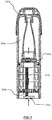
- FIG 19 shows a schematic longitudinal cross sectional view of the smoking substitute apparatus forming part of the smoking substitute system shown in Figures 17 and 18 .
- the e-liquid 160 is stored within a reservoir in the form of a tank 152 that forms part of the consumable 150.
- the consumable 150 is a "single-use" consumable 150. That is, upon exhausting the e-liquid 160 in the tank 152, the intention is that the user disposes of the entire consumable 150.
- the term "single-use” does not necessarily mean the consumable is designed to be disposed of after a single smoking session. Rather, it defines the consumable 150 is not arranged to be refilled after the e-liquid contained in the tank 152 is depleted.
- the tank may include a vent (not shown) to allow ingress of air to replace e-liquid that has been used from the tank.
- the consumable 150 preferably includes a window 158 (see Figures 17 and 18 ), so that the amount of e-liquid in the tank 152 can be visually assessed.
- the main body 120 includes a slot 157 so that the window 158 of the consumable 150 can be seen whilst the rest of the tank 152 is obscured from view when the consumable 150 is received in the cavity of the main body 120.
- the consumable 150 may be referred to as a "clearomizer” when it includes a window 158, or a "cartomizer” when it does not.
- the e-liquid i.e. aerosol precursor
- the tank may be refillable with e-liquid or the e-liquid may be stored in a non-consumable component of the system.
- the e-liquid may be stored in a tank located in the main body or stored in another component that is itself not single-use (e.g. a refillable cartomizer).
- the external wall of tank 152 is provided by a casing of the consumable 150.
- the tank 152 annularly surrounds, and thus defines a portion of, a passage 170 that extends between a vaporiser inlet 172 and an outlet 174 at opposing ends of the consumable 150.
- the passage 170 comprises an upstream end at the end of the consumable 150 that engages with the main body 120, and a downstream end at an opposing end of the consumable 150 that comprises a mouthpiece 154 of the system 110.
- a plurality of device air inlets 176 are formed at the boundary between the casing of the consumable and the casing of the main body.
- the device air inlets 176 are in fluid communication with the vaporiser inlet 172 through an inlet flow channel 178 formed in the cavity of the main body which is of corresponding shape to receive a part of the consumable 150. Air from outside of the system 110 can therefore be drawn into the passage 170 through the device air inlets 176 and the inlet flow channels 178.
- the passage 170 may be partially defined by a tube (e.g. a metal tube) extending through the consumable 150.
- the passage 170 is shown with a substantially circular cross-sectional profile with a constant diameter along its length.
- the passage may have other cross-sectional profiles, such as oval shaped or polygonal shaped profiles.
- the cross sectional profile and the diameter (or hydraulic diameter) of the passage may vary along its longitudinal axis.
- the smoking substitute system 110 is configured to vaporise the e-liquid 160 for inhalation by a user.
- the consumable 150 comprises a heater having a porous wick 162 and a resistive heating element in the form of a heating filament 164 that is helically wound (in the form of a coil) around a portion of the porous wick 162.
- the porous wick 162 extends across the passage 170 (i.e. transverse to a longitudinal axis of the passage 170 and thus also transverse to the air flow along the passage 170 during use) and opposing ends of the wick 162 extend into the tank 152 (so as to be immersed in the e-liquid 160). In this way, e-liquid 160 contained in the tank 152 is conveyed from the opposing ends of the porous wick 162 to a central portion of the porous wick 162 so as to be exposed to the airflow in the passage 170.
- the helical filament 164 is wound about the exposed central portion of the porous wick 162 and is electrically connected to an electrical interface in the form of electrical contacts 156 mounted at the end of the consumable that is proximate the main body 120 (when the consumable and the main body are engaged).
- electrical contacts 156 make contact with corresponding electrical contacts (not shown) of the main body 120.
- the main body electrical contacts are electrically connectable to a power source (not shown) of the main body 120, such that (in the engaged position) the filament 164 is electrically connectable to the power source. In this way, power can be supplied by the main body 120 to the filament 164 in order to heat the filament 164.
- the filament 164 and the exposed central portion of the porous wick 162 are positioned across the passage 170. More specifically, the part of passage that contains the filament 164 and the exposed portion of the porous wick 162 forms a vaporisation chamber.
- the vaporisation chamber has the same cross-sectional diameter as the passage 170.
- the vaporisation chamber may have a different cross sectional profile compared with the passage 170.
- the vaporisation chamber may have a larger cross sectional diameter than at least some of the downstream part of the passage 170 so as to enable a longer residence time for the air inside the vaporisation chamber.
- FIG 20 illustrates in more detail the vaporisation chamber and therefore the region of the consumable 150 around the wick 162 and filament 164.
- the helical filament 164 is wound around a central portion of the porous wick 162.
- the porous wick extends across passage 170.
- E-liquid 160 contained within the tank 152 is conveyed as illustrated schematically by arrows 401, i.e. from the tank and towards the central portion of the porous wick 162.
- porous wick 162 When the user inhales, air is drawn from through the inlets 176 shown in Figure 19 , along inlet flow channel 178 to vaporisation chamber inlet 172 and into the vaporisation chamber containing porous wick 162.
- the porous wick 162 extends substantially transverse to the airflow direction.
- the airflow passes around the porous wick, at least a portion of the airflow substantially following the surface of the porous wick 162.
- the airflow may follow a curved path around an outer periphery of the porous wick 162.
- the filament 164 is heated so as to vaporise the e-liquid which has been wicked into the porous wick.
- the airflow passing around the porous wick 162 picks up this vaporised e-liquid, and the vapour-containing airflow is drawn in direction 403 further down passage 170.
- the power source of the main body 120 may be in the form of a battery (e.g. a rechargeable battery such as a lithium ion battery).
- the main body 120 may comprise a connector in the form of e.g. a USB port for recharging this battery.
- the main body 120 may also comprise a controller that controls the supply of power from the power source to the main body electrical contacts (and thus to the filament 164). That is, the controller may be configured to control a voltage applied across the main body electrical contacts, and thus the voltage applied across the filament 164. In this way, the filament 164 may only be heated under certain conditions (e.g. during a puff and/or only when the system is in an active state).
- the main body 120 may include a puff sensor (not shown) that is configured to detect a puff (i.e. inhalation).
- the puff sensor may be operatively connected to the controller so as to be able to provide a signal, to the controller, which is indicative of a puff state (i.e. puffing or not puffing).
- the puff sensor may, for example, be in the form of a pressure sensor or an acoustic sensor.
- the main body 120 and consumable 150 may comprise a further interface which may, for example, be in the form of an RFID reader, a barcode or QR code reader.
- This interface may be able to identify a characteristic (e.g. a type) of a consumable 150 engaged with the main body 120.
- the consumable 150 may include anyone or more of an RFID chip, a barcode or QR code, or memory within which is an identifier and which can be interrogated via the interface.
- Aerosol droplet size is a considered to be an important characteristic for smoking substitution devices. Droplets in the range of 2-5 ⁇ m are preferred in order to achieve improved nicotine delivery efficiency and to minimise the hazard of second-hand smoking. However, at the time of writing (September 2019), commercial EVP devices typically deliver aerosols with droplet size averaged around 0.5 ⁇ m, and to the knowledge of the inventors not a single commercially available device can deliver an aerosol with an average particle size exceeding 1 ⁇ m.
- the present inventors speculate, without themselves wishing to be bound by theory, that there has to date been a lack of understanding in the mechanisms of e-liquid evaporation, nucleation and droplet growth in the context of aerosol generation in smoking substitute devices. The present inventors have therefore studied these issues in order to provide insight into mechanisms for the generation of aerosols with larger particles. The present inventors have carried out experimental and modelling work alongside theoretical investigations, leading to significant achievements as now reported.
- This disclosure considers the roles of air velocity, air turbulence and vapour cooling rate in affecting aerosol particle size.
- a Malvern PANalytical Spraytec laser diffraction system was employed for the particle size measurement.
- the same coil and wick 1.5 ohms Ni-Cr coil, 1.8 mm Y07 cotton wick
- Y07 represents the grade of cotton wick, meaning that the cotton has a linear density of 0.7 grams per meter.
- Particle sizes were measured in accordance with ISO 13320:2009(E), which is an international standard on laser diffraction methods for particle size analysis. This is particularly well suited to aerosols, because there is an assumption in this standard that the particles are spherical (which is a good assumption for liquid-based aerosols). The standard is stated to be suitable for particle sizes in the range 0.1 micron to 3 mm.
- Figure 2 shows a schematic perspective longitudinal cross sectional view of an example rectangular tube 1170 with a wick 1162 and heater coil 1164 installed.
- the location of the wick is about half way along the length of the tube. This is intended to allow the flow of air along the tube to settle before reaching the wick.
- Figure 3 shows a schematic transverse cross sectional view an example rectangular tube 1170 with a wick 1162 and heater coil 1164 installed.
- the internal width of the tube is 12 mm
- the rectangular tubes were manufactured to have same internal depth of 6 mm in order to accommodate the standardized coil and wick, however the tube internal width varied from 4.5 mm to 50 mm.
- the "tube size” is referred to as the internal width of rectangular tubes.
- the rectangular tubes with different dimensions were used to generate aerosols that were tested for particle size in a Malvern PANalytical Spraytec laser diffraction system.
- An external digital power supply was dialled to 2.6A constant current to supply 10W power to the heater coil in all experiments. Between two runs, the wick was saturated manually by applying one drop of e-liquid on each side of the wick.
- Table 1 shows a list of experiments in this study.
- the values in "calculated air velocity” column were obtained by simply dividing the flow rate by the intersection area at the centre plane of wick.
- Turbulence intensity was introduced as a quantitative parameter to assess the level of turbulence. The definition and simulation of turbulence intensity is discussed below (see section 3.2).
- Figures 4A-4D show air flow streamlines in the four devices used in this turbulence study.
- Figure 4A is a standard 12mm rectangular tube with wick and coil installed as explained in the previous section, with no jetting panel.
- Figure 4B has a jetting panel located 10mm below (upstream from) the wick.
- Figure 4C has the same jetting panel 5mm below the wick.
- Figure 4D has the same jetting panel 2.5mm below the wick.
- the jetting panel has an arrangement of apertures shaped and directed in order to promote jetting from the downstream face of the panel and therefore to promote turbulent flow.
- the jetting panel can introduce turbulence downstream, and the panel causes higher level of turbulence near the wick when it is positioned closer to the wick.
- the four geometries gave turbulence intensities of 0.55%, 0.77%, 1.06% and 1.34%, respectively, with Figure 4A being the least turbulent, and Figure 4D being the most turbulent.
- the experimental set up is shown in Figure 5 .
- the testing used a Carbolite Gero EHA 12300B tube furnace 3210 with a quartz tube 3220 to heat up the air. Hot air in the tube furnace was then led into a transparent housing 3158 that contains the EVP device 3150 to be tested.
- a thermocouple meter 3410 was used to assess the temperature of the air pulled into the EVP device. Once the EVP device was activated, the aerosol was pulled into the Spraytec laser diffraction system 3310 via a silicone connector 3320 for particle size measurement.
- pod 1 is the commercially available "myblu optimised" pod ( Figure 6 ); pod 2 is a pod featuring an extended inflow path upstream of the wick ( Figure 7 ); and pod 3 is pod with the wick located in a stagnant vaporisation chamber and the inlet air bypassing the vaporisation chamber but entraining the vapour from an outlet of the vaporisation chamber ( Figures 8A and 8B ).
- Pod 1 shown in longitudinal cross sectional view (in the width plane) in Figure 6 , has a main housing that defines a tank 160x holding an e-liquid aerosol precursor. Mouthpiece 154x is formed at the upper part of the pod. Electrical contacts 156x are formed at the lower end of the pod. Wick 162x is held in a vaporisation chamber. The air flow direction is shown using arrows.
- Pod 2 shown in longitudinal cross sectional view (in the width plane) in Figure 7 , has a main housing that defines a tank 160y holding an e-liquid aerosol precursor. Mouthpiece 154y is formed at the upper part of the pod. Electrical contacts 156y are formed at the lower end of the pod. Wick 162y is held in a vaporisation chamber. The air flow direction is shown using arrows. Pod 2 has an extended inflow path (plenum chamber 157y) with a flow conditioning element 159y, configured to promote reduced turbulence at the wick 162y.
- Figure 8A shows a schematic longitudinal cross sectional view of pod 3.
- Figure 8B shows a schematic longitudinal cross sectional view of the same pod 3 in a direction orthogonal to the view taken in Figure 8A .
- Pod 3 has a main housing that defines a tank 160z holding an e-liquid aerosol precursor. Mouthpiece 154z is formed at the upper part of the pod. Electrical contacts 156z are formed at the lower end of the pod. Wick 162z is held in a vaporisation chamber. The air flow direction is shown using arrows.
- Pod 3 uses a stagnant vaporiser chamber, with the air inlets bypassing the wick and picking up the vapour/aerosol downstream of the wick.
- Air velocity in the vicinity of the wick is believed to play an important role in affecting particle size.
- the air velocity was calculated by dividing the flow rate by the intersection area, which is referred to as "calculated velocity" in this work. This involves a very crude simplification that assumes velocity distribution to be homogeneous across the intersection area.
- the CFD model uses a laminar single-phase flow setup.
- the outlet was configured to a corresponding flowrate
- the inlet was configured to be pressure-controlled
- the wall conditions were set as "no slip”.
- a 1 mm wide ring-shaped domain (wick vicinity) was created around the wick surface, and domain probes were implemented to assess the average and maximum magnitudes of velocity in this ring-shaped wick vicinity domain.
- the CFD model outputs the average velocity and maximum velocity in the vicinity of the wick for each set of experiments carried out in section 2.1. The outcomes are reported in Table 2.
- turbulence intensity values represent higher levels of turbulence.
- turbulence intensity below 1% represents a low-turbulence case
- turbulence intensity between 1% and 5% represents a medium-turbulence case
- turbulence intensity above 5% represents a high-turbulence case.
- Turbulence intensity was assessed within the volume up to 1 mm away from the wick surface (defined as the wick vicinity domain). For the four experiments explained in section 2.2, the turbulence intensities are 0.55%, 0.77%, 1.06% and 1.34%, respectively, as also shown in Figures 4A-4D .
- the cooling rate modelling involves three coupling models in COMSOL Multiphysics: 1) laminar two-phase flow; 2) heat transfer in fluids, and 3) particle tracing.
- the model is setup in three steps:
- Laminar mixture flow physics was selected in this study.
- the outlet was configured in the same way as in section 3.1.
- this model includes two fluid phases released from two separate inlets: the first one is the vapour released from wick surface, at an initial velocity of 2.84 cm/s (calculated based on 5 mg total particulate mass over 3 seconds puff duration) with initial velocity direction normal to the wick surface; the second inlet is air influx from the base of tube, the rate of which is pressure-controlled.
- the inflow and outflow settings in heat transfer physics was configured in the same way as in the two-phase flow model.
- the air inflow was set to 25 °C
- the vapour inflow was set to 209 °C (boiling temperature of the e-liquid formulation).
- the heat transfer physics is configured to be two-way coupled with the laminar mixture flow physics.
- the above model reaches steady state after approximately 0.2 second with a step size of 0.001 second.
- the particle tracing physics has one-way coupling with the previous model, which means the fluid flow exerts dragging force on the particles, whereas the particles do not exert counterforce on the fluid flow. Therefore, the particles function as moving probes to output vapour temperature at each timestep.
- the model outputs average vapour temperature at each time steps.
- a MATLAB script was then created to find the time step when the vapour cools to a target temperature (50°C or 75°C), based on which the vapour cooling rates were obtained (Table 3).
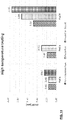
- Table 3 Average vapour cooling rate obtained from Multiphysics modelling Tube size Flow rate Cooling rate to 50°C Cooling rate to 75°C [mm] [lpm] [°C/ms] [°C/ms] 1.3 lpm constant flow rate 4.5 1.3 11.4 44.7 6 1.3 5.48 14.9 7 1.3 3.46 7.88 8 1.3 2.24 5.15 10 1.3 1.31 2.85 12 1.3 0.841 1.81 20 1.3 0* 0.536 50 1.3 0 0 2.0 lpm constant flow rate 4.5 2.0 19.9 670 5 2.0 13.3 67 6 2.0 8.83 26.8 8 2.0 3.61 8.93 12 2.0 1.45 3.19 20 2.0 0.395 0.761 50 2.0 0 0 * Zero cooling rate when the average vapour temperature is still above target temperature after
- Particle size measurement results for the rectangular tube testing are shown in Table 4.
- Table 4 For every tube size and flow rate combination, five repetition runs were carried out in the Spraytec laser diffraction system. The Dv50 values from five repetition runs were averaged, and the standard deviations were calculated to indicate errors, as shown in Table 4.
- the particle size (Dv50) experimental results are plotted against calculated air velocity in Figure 9 .
- the graph shows a strong correlation between particle size and air velocity.
- Figure 10 shows the results of three experiments with highly different setup arrangements: 1) 5mm tube measured at 1.4 Ipm flow rate with Reynolds number of 155; 2) 8mm tube measured at 2.8 Ipm flow rate with Reynolds number of 279; and 3) 20mm tube measured at 8.6 Ipm flow rate with Reynolds number of 566. It is relevant that these setup arrangements have one similarity: the air velocities are all calculated to be 1 m/s.
- Figure 10 shows that, although these three sets of experiments have different tube sizes, flow rates and Reynolds numbers, they all delivered similar particle sizes, as the air velocity was kept constant. These three data points were also plotted out in Figure 9 (1 m/s data with star marks) and they tie in nicely into particle size-air velocity trendline.
- the particle size measurement data were plotted against the average velocity ( Figure 11 ) and maximum velocity ( Figure 12 ) in the vicinity of the wick, as obtained from CFD modelling.
- the data in these two graphs indicates that in order to obtain an aerosol with Dv50 larger than 1 ⁇ m, the average velocity should be less than or equal to 1.2 m/s in the vicinity of the wick and the maximum velocity should be less than or equal to 2.0 m/s in the vicinity of the wick.
- the average velocity should be less than or equal to 0.6 m/s in the vicinity of the wick and the maximum velocity should be less than or equal to 1.2 m/s in the vicinity of the wick.
- typical commercial EVP devices deliver aerosols with Dv50 around 0.5 ⁇ m, and there is no commercially available device that can deliver aerosol with Dv50 exceeding 1 ⁇ m. It is considered that typical commercial EVP devices have average velocity of 1.5-2.0 m/s in the vicinity of the wick.
- turbulence intensity is a quantitative characteristic that indicates the level of turbulence.
- four tubes of different turbulence intensities were used to general aerosols which were measured in the Spraytec laser diffraction system.
- the particle size (Dv50) experimental results are plotted against turbulence intensity in Figure 13 .
- the graph suggests a correlation between particle size and turbulence intensity, that lower turbulence intensity is beneficial for obtaining larger particle size. It is noted that when turbulence intensity is above 1% (medium-turbulence case), there are relatively large measurement fluctuations. In Figure 13 , the tube with a jetting panel 10mm below the wick has the largest error bar, because air jets become unpredictable near the wick after traveling through a long distance.
- Figure 14 shows the high temperature testing results. Larger particle sizes were observed from all 3 pods when the temperature of inlet air increased from room temperature (23°C) to 50 °C. When the pods were heated as well, two of the three pods saw even larger particle size measurement results, while pod 2 was unable to be measured due to significant amount of leakage.
- laminar flow allows slow and gradual mixing between cold air and hot vapour, which means the vapour can cool down in slower rate when the airflow is laminar, resulting in larger particle size.
- vapour cooling rates for each tube size and flow rate combination were obtained via multiphysics simulation.
- particle size measurement results were plotted against vapour cooling rate to 50°C and 75°C, respectively.
- the apparatus in order to obtain an aerosol with Dv50 larger than 1 ⁇ m, the apparatus should be operable to require more than 16 ms for the vapour to cool to 50°C, or an equivalent (simplified to an assumed linear) cooling rate being slower than 10 °C/ms.
- the apparatus in order to obtain an aerosol with Dv50 larger than 1 ⁇ m, the apparatus should be operable to require more than 4.5 ms for the vapour to cool to 75°C, or an equivalent (simplified to an assumed linear) cooling rate slower than 30 °C/ms.
- the apparatus should be operable to require more than 32 ms for the vapour to cool to 50°C, or an equivalent (simplified to an assumed linear) cooling rate being slower than 5 °C/ms.
- the apparatus in order to obtain an aerosol with Dv50 of 2 ⁇ m or larger, should be operable to require more than 13 ms for the vapour to cool to 75°C, or an equivalent (simplified to an assumed linear) cooling rate slower than 10 °C/ms.
- particle size (Dv50) of aerosols generated in a set of rectangular tubes was studied in order to decouple different factors (flow rate, air velocity, Reynolds number, tube size) affecting aerosol particle size. It is considered that air velocity is an important factor affecting particle size - slower air velocity leads to larger particle size. When air velocity was kept constant, the other factors (flow rate, Reynolds number, tube size) has low influence on particle size.
Priority Applications (4)
| Application Number | Priority Date | Filing Date | Title |
|---|---|---|---|
| EP19198722.1A EP3795012A1 (fr) | 2019-09-20 | 2019-09-20 | Appareil de substitution du tabac |
| EP20789856.0A EP3930518A1 (fr) | 2019-09-20 | 2020-09-21 | Appareil de substitution au tabagisme |
| PCT/EP2020/076311 WO2021053233A1 (fr) | 2019-09-20 | 2020-09-21 | Appareil de substitution au tabagisme |
| US17/697,072 US20220202092A1 (en) | 2019-09-20 | 2022-03-17 | Smoking substitute apparatus |
Applications Claiming Priority (1)
| Application Number | Priority Date | Filing Date | Title |
|---|---|---|---|
| EP19198722.1A EP3795012A1 (fr) | 2019-09-20 | 2019-09-20 | Appareil de substitution du tabac |
Publications (1)
| Publication Number | Publication Date |
|---|---|
| EP3795012A1 true EP3795012A1 (fr) | 2021-03-24 |
Family
ID=67998377
Family Applications (1)
| Application Number | Title | Priority Date | Filing Date |
|---|---|---|---|
| EP19198722.1A Ceased EP3795012A1 (fr) | 2019-09-20 | 2019-09-20 | Appareil de substitution du tabac |
Country Status (1)
| Country | Link |
|---|---|
| EP (1) | EP3795012A1 (fr) |
Citations (4)
| Publication number | Priority date | Publication date | Assignee | Title |
|---|---|---|---|---|
| EP2319334A1 (fr) * | 2009-10-27 | 2011-05-11 | Philip Morris Products S.A. | Système de fumage ayant une partie de stockage de liquide |
| WO2013083638A1 (fr) * | 2011-12-08 | 2013-06-13 | Philip Morris Products S.A. | Dispositif de génération d'aérosol à buses d'écoulement d'air |
| US20160073692A1 (en) * | 2014-09-17 | 2016-03-17 | Fontem Holdings 2 B.V. | Device for storing and vaporizing liquid media |
| GB2566766A (en) * | 2017-09-22 | 2019-03-27 | Nerudia Ltd | Device, system and method |
-
2019
- 2019-09-20 EP EP19198722.1A patent/EP3795012A1/fr not_active Ceased
Patent Citations (4)
| Publication number | Priority date | Publication date | Assignee | Title |
|---|---|---|---|---|
| EP2319334A1 (fr) * | 2009-10-27 | 2011-05-11 | Philip Morris Products S.A. | Système de fumage ayant une partie de stockage de liquide |
| WO2013083638A1 (fr) * | 2011-12-08 | 2013-06-13 | Philip Morris Products S.A. | Dispositif de génération d'aérosol à buses d'écoulement d'air |
| US20160073692A1 (en) * | 2014-09-17 | 2016-03-17 | Fontem Holdings 2 B.V. | Device for storing and vaporizing liquid media |
| GB2566766A (en) * | 2017-09-22 | 2019-03-27 | Nerudia Ltd | Device, system and method |
Similar Documents
| Publication | Publication Date | Title |
|---|---|---|
| US20220202092A1 (en) | Smoking substitute apparatus | |
| EP3930496A1 (fr) | Appareil de substitution pour fumeur | |
| US20220378105A1 (en) | Smoking substitute apparatus | |
| EP3795013A1 (fr) | Appareil de substitution du tabac | |
| EP3795007A1 (fr) | Appareil de substitution du tabac | |
| EP3795009A1 (fr) | Appareil de substitution du tabac | |
| EP3794969A1 (fr) | Appareil de substitution du tabac | |
| EP3794997A1 (fr) | Appareil de substitution du tabac | |
| EP3794975A1 (fr) | Appareil de substitution du tabac | |
| EP3795012A1 (fr) | Appareil de substitution du tabac | |
| EP3795002A1 (fr) | Appareil de substitution du tabac | |
| EP3795011A1 (fr) | Appareil de substitution du tabac | |
| EP3795001A1 (fr) | Appareil de substitution du tabac | |
| EP3794967A1 (fr) | Appareil de substitution du tabac | |
| EP3794988A1 (fr) | Appareil de substitution du tabac | |
| EP3795003A1 (fr) | Appareil de substitution du tabac | |
| US20220256918A1 (en) | Smoking substitute apparatus | |
| EP3794982A1 (fr) | Appareil de substitution du tabac | |
| EP3794980A1 (fr) | Appareil de substitution du tabac | |
| US20220192260A1 (en) | Smoking substitute apparatus | |
| EP3794972A1 (fr) | Appareil de substitution du tabac | |
| EP3895554A1 (fr) | Appareil de substitution du tabac | |
| EP3795008A1 (fr) | Appareil de substitution du tabac | |
| EP3794968A1 (fr) | Appareil de substitution du tabac | |
| EP3794992A1 (fr) | Appareil de substitution du tabac |
Legal Events
| Date | Code | Title | Description |
|---|---|---|---|
| PUAI | Public reference made under article 153(3) epc to a published international application that has entered the european phase |
Free format text: ORIGINAL CODE: 0009012 |
|
| STAA | Information on the status of an ep patent application or granted ep patent |
Free format text: STATUS: THE APPLICATION HAS BEEN PUBLISHED |
|
| AK | Designated contracting states |
Kind code of ref document: A1 Designated state(s): AL AT BE BG CH CY CZ DE DK EE ES FI FR GB GR HR HU IE IS IT LI LT LU LV MC MK MT NL NO PL PT RO RS SE SI SK SM TR |
|
| AX | Request for extension of the european patent |
Extension state: BA ME |
|
| STAA | Information on the status of an ep patent application or granted ep patent |
Free format text: STATUS: THE APPLICATION HAS BEEN REFUSED |
|
| 18R | Application refused |
Effective date: 20210424 |