EP3794985A1 - Composant de substitution du tabac - Google Patents
Composant de substitution du tabac Download PDFInfo
- Publication number
- EP3794985A1 EP3794985A1 EP19198615.7A EP19198615A EP3794985A1 EP 3794985 A1 EP3794985 A1 EP 3794985A1 EP 19198615 A EP19198615 A EP 19198615A EP 3794985 A1 EP3794985 A1 EP 3794985A1
- Authority
- EP
- European Patent Office
- Prior art keywords
- passage
- absorbent element
- component according
- tank
- airflow path
- Prior art date
- Legal status (The legal status is an assumption and is not a legal conclusion. Google has not performed a legal analysis and makes no representation as to the accuracy of the status listed.)
- Ceased
Links
Images


Classifications
-
- A—HUMAN NECESSITIES
- A24—TOBACCO; CIGARS; CIGARETTES; SIMULATED SMOKING DEVICES; SMOKERS' REQUISITES
- A24F—SMOKERS' REQUISITES; MATCH BOXES; SIMULATED SMOKING DEVICES
- A24F40/00—Electrically operated smoking devices; Component parts thereof; Manufacture thereof; Maintenance or testing thereof; Charging means specially adapted therefor
- A24F40/40—Constructional details, e.g. connection of cartridges and battery parts
-
- A—HUMAN NECESSITIES
- A24—TOBACCO; CIGARS; CIGARETTES; SIMULATED SMOKING DEVICES; SMOKERS' REQUISITES
- A24F—SMOKERS' REQUISITES; MATCH BOXES; SIMULATED SMOKING DEVICES
- A24F40/00—Electrically operated smoking devices; Component parts thereof; Manufacture thereof; Maintenance or testing thereof; Charging means specially adapted therefor
- A24F40/10—Devices using liquid inhalable precursors
Definitions
- the present disclosure relates to an aerosol-delivery component, which may be a consumable component for receipt in an aerosol-delivery device to form an aerosol-delivery system (e.g. a smoking substitute system).
- an aerosol-delivery component which may be a consumable component for receipt in an aerosol-delivery device to form an aerosol-delivery system (e.g. a smoking substitute system).
- the smoking of tobacco is generally considered to expose a smoker to potentially harmful substances. It is generally thought that a significant amount of the potentially harmful substances are generated through the heat caused by the burning and/or combustion of the tobacco and the constituents of the burnt tobacco in the tobacco smoke itself.
- Such smoking substitute systems can form part of nicotine replacement therapies aimed at people who wish to stop smoking and overcome a dependence on nicotine.
- Smoking substitute systems which may also be known as electronic nicotine delivery systems, may comprise electronic systems that permit a user to simulate the act of smoking by producing an aerosol, also referred to as a "vapour", which is drawn into the lungs through the mouth (inhaled) and then exhaled.
- the inhaled aerosol typically bears nicotine and/or flavourings without, or with fewer of, the odour and health risks associated with traditional smoking.
- smoking substitute systems are intended to provide a substitute for the rituals of smoking, whilst providing the user with a similar experience and satisfaction to those experienced with traditional smoking and tobacco products.
- smoking substitute systems are designed to resemble a traditional cigarette and are cylindrical in form with a mouthpiece at one end.
- Other smoking substitute systems do not generally resemble a cigarette (for example, the smoking substitute device may have a generally box-like form).
- a smoking substitute approach corresponds to the manner in which the substitute system operates for a user.
- a smoking substitute system is the so-called “vaping” approach, in which a vaporisable liquid, typically referred to (and referred to herein) as “e-liquid", is heated by a heater to produce an aerosol vapour which is inhaled by a user.
- An e-liquid typically includes a base liquid as well as nicotine and/or flavourings.
- the resulting vapour therefore typically contains nicotine and/or flavourings.
- the base liquid may include propylene glycol and/or vegetable glycerine.
- a typical vaping smoking substitute system includes a mouthpiece, a power source (typically a battery), a tank or liquid reservoir for containing e-liquid, as well as a heater.
- a power source typically a battery
- a tank or liquid reservoir for containing e-liquid as well as a heater.
- electrical energy is supplied from the power source to the heater, which heats the e-liquid to produce an aerosol (or "vapour") which is inhaled by a user through the mouthpiece.
- Vaping smoking substitute systems can be configured in a variety of ways.
- there are "closed system" vaping smoking substitute systems which typically have a heater and a sealed tank which is pre-filled with e-liquid and is not intended to be refilled by an end user.
- One subset of closed system vaping smoking substitute systems include a device which includes the power source, wherein the device is configured to be physically and electrically coupled to a consumable including the tank and the heater. In this way, when the tank of a consumable has been emptied, the device can be reused by connecting it to a new consumable.
- Another subset of closed system vaping smoking substitute systems are completely disposable, and intended for one-use only.
- vaping smoking substitute systems which typically have a tank that is configured to be refilled by a user, so the system can be used multiple times.
- An example vaping smoking substitute system is the mybluTM e-cigarette.
- the mybluTM e cigarette is a closed system which includes a device and a consumable.
- the device and consumable are physically and electrically coupled together by pushing the consumable into the device.
- the device includes a rechargeable battery.
- the consumable includes a mouthpiece, a sealed tank which contains e-liquid, as well as a vaporiser, which for this system is a heating filament coiled around a portion of a wick which is partially immersed in the e-liquid.
- the system is activated when a microprocessor on board the device detects a user inhaling through the mouthpiece. When the system is activated, electrical energy is supplied from the power source to the vaporiser, which heats e-liquid from the tank to produce a vapour which is inhaled by a user through the mouthpiece.
- the blu PROTM e-cigarette is an open system which includes a device, a (refillable) tank, and a mouthpiece.
- the device and tank are physically and electrically coupled together by screwing one to the other.
- the mouthpiece and refillable tank are physically coupled together by screwing one into the other, and detaching the mouthpiece from the refillable tank allows the tank to be refilled with e-liquid.
- the system is activated by a button on the device. When the system is activated, electrical energy is supplied from the power source to a vaporiser, which heats e-liquid from the tank to produce a vapour which is inhaled by a user through the mouthpiece.
- the vapour passes through the consumable (entrained in the airflow) from the location of vaporization to an outlet of the consumable (e.g. a mouthpiece), the vapour cools and condenses to form an aerosol for inhalation by the user.
- the aerosol may contain nicotine and/or flavour compounds.
- e-liquid in the vaporiser i.e. received from the tank
- leakage may occur whilst the system is not in use.
- leakage can occur when the system (e.g. consumable) is stored in a user's pocket, which may stain a user's clothing and is thus undesirable.
- a smoking substitute component comprising:
- an airflow path portion that extends longitudinally from an air inlet formed in a side wall towards a base portion of the housing may help to prevent or reduce leakage from the housing. This arrangement makes it more difficult for any liquid in the vaporiser to pass from the vaporiser to the air inlet.
- the provision an absorbent element in the passage within the longitudinal portion of the airflow path may further reduce or prevent leakage of liquid from the component.
- the absorbent element may be elongate (i.e. in the longitudinal direction). An end (e.g. that is distal from the base portion) of the absorbent element may be tapered.
- the absorbent element may be formed of a porous material (i.e. configured to capture/absorb liquid leaking into the passage).
- the absorbent element may have a transverse cross-sectional area that is less than a transverse cross-sectional area of the passage (i.e. for a given axial/longitudinal location). That is, the absorbent element may be configured so as to only extend only partway across the passage (i.e. so as to only partly fill the passage). Thus, the airflow path portion may be defined between the absorbent element and a wall of the passage.
- the absorbent element may have a longitudinally extending groove or recess formed therein.
- the absorbent element may have substantially the same transverse cross-sectional shape as the passage, except for a cut-out defined by the recess or groove formed therein.
- the recess or groove may define the airflow path portion (with one or more walls of the passage).
- the airflow path portion may have a substantially rectangular transverse cross-sectional shape.
- a portion of the absorbent element may be adjacent the air inlet.
- the absorbent element may extend within a portion of the passage at which the air inlet joins the passage.
- the absorbent element may be disposed on an opposite side (i.e. in a transverse direction) of the passage to the air inlet.
- a portion the passage may extend longitudinally from the air inlet in a direction away from the base portion (i.e. towards the mouthpiece portion).
- the air inlet may be disposed partway along the length of the passage.
- the absorbent element may extend for substantially the entire length of the passage.
- the length of the absorbent element may be greater than 90% of the length of the passage, or e.g. greater than 95% of the length of the passage.
- An end of the absorbent element (e.g. proximate the vaporiser) may be spaced from a corresponding end (e.g. proximate the vaporiser) of the passage.
- a void may be defined between the end of the absorbent element and the end of the passage.
- the void may be located at an end of the passage proximate the vaporiser. That is, the absorbent element may be spaced from the end of the passage proximate the vaporiser.
- the void may prevent liquid from travelling along the absorbent element from the vaporiser (e.g. to the air inlet).
- the passage may, for example, comprise a retaining portion (e.g. a protrusion) for retaining the absorbent element in this position (i.e. defining the void).
- the air inlet may be longitudinally spaced from the base of the housing by a distance that is greater than 8 mm.
- the distance may be greater than 10 mm, or e.g. greater than 13 mm.
- the portion of the airflow path may be a first portion.
- the airflow path may further comprise a transversely extending second portion.
- the second portion may be perpendicular to the first portion.
- the second portion may be downstream of the first portion (e.g. immediately downstream).
- the vaporiser may be disposed in the second portion.
- the vaporiser may comprise a heating element for heating a wick.
- the wick may extend across the second (transverse) portion of the airflow path.
- the airflow path may comprise a third portion extending longitudinally from the second portion to the air outlet (formed in the mouthpiece portion).
- a user may draw fluid (e.g. air) into and along the airflow path by inhaling at the air outlet (i.e. using the mouthpiece portion).
- the passage (defining the first portion of the airflow path) may be a first passage, and a second (longitudinally extending) passage may define the third portion of the airflow path.
- the second passage may extend longitudinally from the mouthpiece portion towards the base portion of the housing.
- the previously mentioned absorbent element may be a first absorbent element and the component may further comprise a second absorbent element disposed in the second passage.
- the second absorbent element may be elongate (i.e. in the longitudinal direction). An end (e.g. that is distal from the base portion) of the second absorbent element may be tapered. The tapered end of the second absorbent element may be proximate (or adjacent to) the air outlet/mouthpiece portion. The second absorbent element may at least partly obstruct the air outlet. The second absorbent element may extend across the air outlet.
- the second absorbent element may have a transverse cross-sectional area that is less than a transverse cross-sectional area of the second passage. That is, the second absorbent element may be configured so as to only extend only partway across the second passage (i.e. so as to only partly fill the second passage). Thus, the third airflow path portion may be defined between the second absorbent element and a wall of the second passage.
- the second absorbent element may have a longitudinally extending groove or recess formed therein.
- the second absorbent element may have substantially the same transverse cross-sectional shape as the second passage, except for a cut-out defined by the recess or groove formed therein.
- the recess or groove may define the third airflow path portion (with one or more walls of the second passage).
- the third airflow path portion may have a substantially rectangular transverse cross-sectional shape.
- the second absorbent element may extend for substantially the entire length of the second passage.
- the length of the second absorbent element may be greater than 90% of the length of the second passage, or e.g. greater than 95% of the length of the second passage.
- An end of the second absorbent element may be spaced from a corresponding (i.e. proximate) end of the second passage.
- a void may be defined between the end of the second absorbent element and the end of the second passage.
- the void may be located at an end of the second passage proximate the vaporiser. That is, the second absorbent element may be spaced from the end of the second passage proximate the vaporiser.
- the void may prevent liquid from travelling along the absorbent element from the vaporiser (e.g. to the air outlet).
- the third portion of the airflow path may be substantially parallel to the first portion of the airflow path.
- the third portion of the airflow path may be longer (i.e. in a longitudinal direction) than the first airflow path.
- the second portion of the airflow path may be substantially perpendicular to the first and/or third portions of the airflow path.
- the airflow path may be generally U-shaped (the first and third portions forming stems of the "U” and the second portion forming the base of the "U").
- the first portion extends from the air inlet towards the base portion (i.e. away from the mouthpiece portion).
- the second portion of the airflow path may connect the first and third portions of the airflow path.
- the airflow path may comprise at least two turns (e.g. each of around 90°) between the vaporiser and the air inlet.
- the airflow path may comprise at least one turn between the vaporiser and the air outlet.
- the component may comprise a tank for housing an aerosol precursor (e.g. a liquid aerosol precursor).
- the aerosol precursor may comprise an e-liquid, for example, comprising a base liquid and e.g. nicotine.
- the base liquid may include propylene glycol and/or vegetable glycerine.
- the component may be a vaping smoking substitute component.
- the second portion of the airflow path may be disposed between (i.e. axially between) the tank and the base portion of the housing.
- the tank may be disposed between (in a transverse direction) the first and the third portions of the airflow path.
- the vaporiser may be disposed between the tank and the base portion of the housing.
- the wick may be disposed between the tank and the base portion of the housing.
- the component e.g. the housing
- the component may comprise a width, length and depth dimensions.
- the depth may be smaller than each of the width and the length.
- the wick may be oriented in the direction of the depth dimension of the component.
- the length of the housing may be greater than the width of the housing.
- the housing may be elongate, and the elongate axis may be in the length direction.
- the housing may comprise opposing front and rear walls spaced by opposing first and second side walls extending therebetween.
- the distance between the first and second side walls of the housing may define a width of the housing.
- the distance between the front and rear walls may define a depth of the housing.
- the width of the housing may be greater than the depth of the housing.
- the wick may be oriented so as to extend in a direction from the front wall to the rear wall i.e. it may be oriented in the direction of the depth dimension of the component. Thus the wick may extend in a direction perpendicular to the direction of air flow in the second portion of the air flow path.
- the first passage may be defined between a wall of the tank and a wall of the housing.
- the wall of the housing partly defining the first passage may be the first side wall of the housing.
- the wall of the tank defining the first passage may be a first tank wall.
- the first side wall and the first tank wall may be integrally formed with one another.
- the first absorbent element may extend along the first tank wall.
- the first absorbent element may be spaced from the first side wall.
- the first portion of the airflow path may be defined between the first absorbent element and the first side wall.
- the second passage may be defined between a wall of the tank and a wall of the housing.
- the wall of the housing partly defining the second passage may be the second side wall of the housing.
- the wall of the tank defining the second passage may be a second tank wall.
- the second side wall and the second tank wall may be integrally formed with one another.
- the second absorbent element may extend along the second tank wall.
- the second absorbent element may be spaced from the second side wall.
- the third portion of the airflow path may be defined between the second absorbent element and the second side wall.
- first side wall, second side wall, first tank wall and second tank wall may all be integrally formed and may additionally be integrally formed with the mouthpiece portion. In that way, the component may be easily manufactured using injection moulding.
- the tank may be disposed between (in a transverse direction) the first and the third portions of the airflow path.
- the first and second tank walls may be spaced from one another so as to define the tank therebetween.
- the first and second tank walls may extend longitudinally from the mouthpiece portion towards the base portion of the housing.
- the first and second tank walls may be substantially parallel.
- Each of the first and second tank walls may extend between (and span) the front and rear walls of the housing.
- Each of the first and second tank walls may extend from the mouthpiece portion (i.e. internally in the housing).
- Each of the first and second tank walls may be integrally formed with the mouthpiece portion.
- the tank may be partly defined by a wall of the housing (e.g. the front or rear wall). At least a portion of one of the walls defining the tank may be translucent. That is, the tank may comprise a window to allow a user to visually assess the quantity of e-liquid in the tank.
- the tank may be referred to as a "clearomizer” if it includes a window, or a “cartomizer” if it does not.
- the vaporiser may be disposed in a vaporising chamber.
- the vaporising chamber may form part of the airflow path (i.e. the second portion of the airflow path).
- the vaporising chamber may be defined by one or more chamber walls.
- Each of the absorbent elements discussed above may be spaced from the one or more chamber walls (i.e. so as to avoid liquid being transported along the absorbent element from the chamber wall).
- the wick may extend between first and second opposing chamber walls.
- the first and second chamber walls may separate (i.e. partially separate) the vaporising chamber from aerosol precursor in the tank.
- the first and second chambers walls may each comprise a respective opening through which a respective end of the wick projects such that the wick is fluid communication with aerosol precursor in the tank.
- aerosol precursor e.g. e-liquid
- the wick may comprise a porous material.
- aerosol precursor may be drawn (e.g. by capillary action) along the wick, from the tank to the exposed portion of the wick.
- a transverse chamber wall (e.g. a third wall) may separate the vaporising chamber from aerosol precursor in the tank.
- the transverse chamber wall may partly define the tank (i.e. a lower end of the tank).
- the vaporising chamber may be defined by an insert received into an open (e.g. lower) end of the housing.
- the chamber walls may be walls of the insert.
- the wick may have an elongate shape.
- the wick may be cylindrical.
- the heating element may be in the form of a filament wound about the wick (e.g. the filament may extend helically about the wick).
- the filament may be wound about the exposed portion of the wick (i.e. the portion of the wick extending across the airflow path).
- the heating element may be electrically connected (or connectable) to a power source.
- the power source may supply electricity to (i.e. apply a voltage across) the heating element so as to heat the heating element.
- liquid stored in the wick i.e. drawn from the tank
- This vapour may subsequently cool to form an aerosol in airflow path (e.g. in the second passage).
- an aerosol-delivery system e.g. a smoking substitute system
- a component according to the first aspect and an aerosol-delivery (e.g. smoking substitute) device.
- the component may be an aerosol-delivery (e.g. a smoking substitute) consumable i.e. in some embodiments the component may be a consumable component for engagement with the aerosol-delivery (e.g. a smoking substitute) device to form the aerosol-delivery (e.g. s smoking substitute) system.
- aerosol-delivery e.g. a smoking substitute
- the component may be a consumable component for engagement with the aerosol-delivery (e.g. a smoking substitute) device to form the aerosol-delivery (e.g. s smoking substitute) system.
- the device may be configured to receive the consumable component.
- the device and the consumable component may be configured to be physically coupled together.
- the consumable component may be at least partially received in a recess of the device, such that there is snap engagement between the device and the consumable component.
- the device and the consumable component may be physically coupled together by screwing one onto the other, or through a bayonet fitting.
- the consumable component may comprise one or more engagement portions for engaging with the device.
- one end of the consumable component i.e. the inlet end
- an opposing end i.e. the outlet end
- the consumable component may define a mouthpiece.
- the consumable component may comprise an electrical interface for interfacing with a corresponding electrical interface of the device.
- One or both of the electrical interfaces may include one or more electrical contacts.
- the electrical interface may be configured to transfer electrical power from the power source to a heating element of the consumable component.
- the electrical interface may also be used to identify the consumable component from a list of known types.
- the electrical interface may additionally or alternatively be used to identify when the consumable component is connected to the device.
- the device may alternatively or additionally be able to detect information about the consumable component via an RFID reader, a barcode or QR code reader.
- This interface may be able to identify a characteristic (e.g. a type) of the consumable.
- the consumable component may include any one or more of an RFID chip, a barcode or QR code, or memory within which is an identifier and which can be interrogated via the interface.
- the component may be integrally formed with the aerosol-delivery (e.g. a smoking substitute) device to form the aerosol-delivery (e.g. s smoking substitute) system.
- the aerosol-delivery e.g. a smoking substitute
- the aerosol-delivery device e.g. a smoking substitute
- the aerosol former e.g. e-liquid
- the aerosol former may be replenished by re-filling a tank that is integral with the device (rather than replacing the consumable).
- Access to the tank (for re-filling of the e-liquid) may be provided via e.g. an opening to the tank that is sealable with a closure (e.g. a cap).
- the device may comprise a power source.
- the device may comprise a controller.
- a memory may be provided and may be operatively connected to the controller.
- the memory may include non-volatile memory.
- the memory may include instructions which, when implemented, cause the controller to perform certain tasks or steps of a method.
- the device may comprise a wireless interface, which may be configured to communicate wirelessly with another device, for example a mobile device, e.g. via Bluetooth®. To this end, the wireless interface could include a Bluetooth® antenna. Other wireless communication interfaces, e.g. WiFi®, are also possible.
- the wireless interface may also be configured to communicate wirelessly with a remote server.
- An airflow (i.e. puff) sensor may be provided that is configured to detect a puff (i.e. inhalation from a user).
- the airflow sensor may be operatively connected to the controller so as to be able to provide a signal to the controller that is indicative of a puff state (i.e. puffing or not puffing).
- the airflow sensor may, for example, be in the form of a pressure sensor or an acoustic sensor.
- the controller may control power supply to a heating element in response to airflow detection by the sensor.
- the control may be in the form of activation of the heating element in response to a detected airflow.
- the airflow sensor may form part of the device.
- a method of using the aerosol-delivery (e.g. smoking substitute) consumable component according to the first aspect comprising engaging the consumable component with an aerosol-delivery (e.g. smoking substitute) device (as described above) having a power source so as to electrically connect the power source to the consumable component (i.e. to the vaporiser of the consumable component).
- an aerosol-delivery e.g. smoking substitute
- a method of forming a consumable component according to the first aspect comprising providing a housing, inserting an absorbent element into the passage defined by the housing, and inserting the insert into an open end of the housing.
- the housing may be formed by way of injection moulding.
- the invention includes the combination of the aspects and preferred features described except where such a combination is clearly impermissible or expressly avoided.
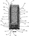
- Fig. 1A shows a smoking substitute system 100.
- the smoking substitute system 100 includes a device 101 and an aerosol delivery consumable component 102.
- the consumable component 102 may alternatively be referred to as a "pod", “cartridge” or “cartomizer”. It should be appreciated that in other examples (i.e. open systems), the device may be integral with the component. In such systems, a tank of the aerosol delivery system may be accessible for refilling the device.
- the smoking substitute system 100 is a closed system vaping system, wherein the consumable component 102 includes a sealed tank 103 and is intended for single-use only.
- the consumable component 102 is removably engageable with the device 101 (i.e. for removal and replacement).
- Fig. 1A shows the smoking substitute system 100 with the device 101 physically coupled to the consumable component 102
- Fig. 1B shows the device 101 of the smoking substitute system 100 without the consumable component 102
- Fig. 1C shows the consumable component 102 of the smoking substitute system 100 without the device 101.
- the device 101 and the consumable component 102 are configured to be physically coupled together by pushing the consumable component 102 into a cavity at an upper end 104 of the device 101, such that there is an interference fit between the device 101 and the consumable component 102.
- the device 101 and the consumable component 102 may be coupled by screwing one onto the other, or through a bayonet fitting.
- the consumable component 102 comprises a housing 105 having a base portion 106 (at a lower end), a mouthpiece portion 107 (at an upper end), and walls extending longitudinally from the base portion 106 to the mouthpiece portion 107.
- the consumable component 102 comprises front 108a and rear walls spaced by opposing first 108c and second 108d side walls.
- the distance between the front 108a and rear 108b walls defines a depth of the housing 105 and the distance between the side walls 108c, 108d defines a width of the housing 105.
- the width of the housing 105 is greater than the depth of the housing 105.
- the tank 103 of the consumable component 102 comprises a window 109, which allows the quantity of e-liquid remaining in the tank 103 to be visually assessed.
- the device 101 includes a slot 110 so that the window 109 of the consumable component 102 can be seen whilst the rest of the tank 103 is obscured from view when the consumable component 102 is inserted into the cavity at the upper end 108 of the device 102.
- a lower end 111 of the device 101 includes a light 112 (e.g. an LED) located behind a small translucent cover.
- the light 112 may be configured to illuminate when the smoking substitute system 100 is activated.
- the consumable component 102 may identify itself to the device 101, via an electrical interface, RFID chip, or barcode.
- Figs. 2A and 2B are schematic drawings of the device 101 and consumable component 102. These figures provide an overview of the components that form part of the consumable component 102 and device 101. As is apparent from Fig. 2A , the device 101 includes a power source 113, a controller 114, a memory 115, a wireless interface 116, an electrical interface 117, and, optionally, one or more additional components 118.
- the power source 113 is a battery (e.g. a rechargeable battery).
- the controller 114 may, for example, include a microprocessor.
- the memory 115 may include non-volatile memory.
- the memory 115 may include instructions which, when implemented, cause the controller 114 to perform certain tasks or steps of a method.
- the wireless interface 116 may be configured to communicate wirelessly with another device, for example a mobile device, e.g. via Bluetooth®. To this end, the wireless interface 116 could include a Bluetooth® antenna. Other wireless communication interfaces, e.g. WiFi®, are also possible. The wireless interface 116 may also be configured to communicate wirelessly with a remote server.
- a mobile device e.g. via Bluetooth®.
- the wireless interface 116 could include a Bluetooth® antenna.
- Other wireless communication interfaces, e.g. WiFi® are also possible.
- the wireless interface 116 may also be configured to communicate wirelessly with a remote server.
- the electrical interface 117 of the device 101 may include one or more electrical contacts.
- the electrical interface 117 may be located in a base of the cavity formed in the upper end 104 of the device 101.
- the electrical interface 117 of the device 101 is configured to transfer electrical power from the power source 113 to the consumable component 102 (i.e. upon activation of the smoking substitute system 100).
- the electrical interface 117 may be configured to receive power from a charging station when the device 101 is not physically coupled to the consumable component 102 and is instead coupled to the charging station.
- the electrical interface 117 may also be used to identify the consumable component 102 from a list of known consumables.
- the consumable component 102 may include e-liquid having a particular flavour and/or having a certain concentration of nicotine (which may be identified by the electrical interface 117). This can be indicated to the controller 114 of the device 101 when the consumable component 102 is connected to the device 101.
- the additional components 118 of the device 101 may comprise an indicator (e.g. the light 112 discussed above), a charging portion, a battery charging control circuit, a sensor or e.g. user input.
- the charging port may be configured to receive power from the charging station (i.e. when the power source 118 is a rechargeable battery). This may be located at the lower end 111 of the device 101. Alternatively, the electrical interface 117 discussed above may be configured to act as a charging port configured to receive power from the charging station such that a separate charging port is not required.
- the battery charging control circuit may be configured for controlling the charging of the rechargeable battery. However, a battery charging control circuit could equally be located in the charging station (if present).
- the sensor may be e.g. an airflow (i.e. puff) sensor for detecting airflow in the smoking substitute system 100, e.g. caused by a user inhaling through a mouthpiece portion 107 of the consumable component 102.
- the smoking substitute system 100 may be configured to be activated when airflow is detected by the airflow sensor. This sensor could alternatively be included in the consumable component 102.
- the airflow sensor can be used to determine, for example, how heavily a user draws on the mouthpiece portion 107 or how many times a user draws on the mouthpiece portion 107 in a particular time period.
- the user input may be a button.
- the smoking substitute system 100 may be configured to be activated when a user interacts with the user input (e.g. presses the button). This provides an alternative to the airflow sensor as a mechanism for activating the smoking substitute system 100.
- the consumable component 102 which is shown in Fig. 2B , includes the tank 103, an electrical interface 119, a vaporiser 120, an air inlet 121, an air outlet 122 (e.g. formed in the mouthpiece portion 107), and one or more additional components 123.
- the electrical interface 119 of the consumable component 102 may include one or more electrical contacts.
- the electrical interface 117 of the device 101 and the electrical interface 119 of the consumable component 102 may be configured to contact each other and thereby electrically couple the device 101 to the consumable component 102 when the base portion 106 of the consumable component 102 is inserted into the cavity formed in the upper end 104 of the device 101 (as shown in Fig. 1A ).
- electrical energy e.g. in the form of an electrical current
- the power source 113 in the device 101 to the vaporiser 120 in the consumable component 102.
- the vaporiser 120 is configured to heat and vaporise e-liquid contained in the tank 103 using electrical energy supplied from the power source 113. As will be described further below, the vaporiser 120 heats the e-liquid received from the tank 103 to vaporise the e-liquid.
- the air inlet 121 is configured to allow air to be drawn into the smoking substitute system 100 when a user inhales using the air outlet 122 formed in the mouthpiece portion 107, such that the vaporised e-liquid is drawn through the consumable component 102 for inhalation by the user.
- a user activates the smoking substitute system 100, e.g. through interaction with a user input forming part of the device 101 or by inhaling through the air outlet 122 as described above.
- the controller 114 may supply electrical energy from the power source 113 to the vaporiser 120 (via electrical interfaces 117, 119), which may cause the vaporiser 120 to heat e-liquid drawn from the tank 103 to produce a vapour which is inhaled by a user through the mouthpiece portion 107.
- An example of one of the one or more additional components 123 of the consumable component 102 is an interface for obtaining an identifier of the consumable component 102.
- this interface may be, for example, an RFID reader, a barcode, a QR code reader, or an electronic interface which is able to identify the consumable component 102.
- the consumable component 102 may, therefore include any one or more of an RFID chip, a barcode or QR code, or memory within which is an identifier and which can be interrogated via the electronic interface 117 in the device 101.
- the smoking substitute system 100 shown in figures 1A to 2B is just one exemplary implementation of a smoking substitute system 100.
- the system could otherwise be in the form of an entirely disposable (single-use) system or an open system in which the tank is refillable (rather than replaceable).
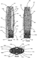
- FIGS 3A , 3B, 3C and 3D are section views of the consumable component 102 described above.
- the air inlet 121 of the consumable component 102 is in the form of an aperture formed in the first side wall 108c of the housing 105.
- the air inlet 121 is spaced along the first side wall 108c (in a longitudinal direction) from the base portion 106 of the housing 105 so as to be partway along the first side wall 108c from the base portion 106.
- the air outlet 122 is formed in the mouthpiece portion 107 and an airflow path 124 extends from the air inlet 121 to the air outlet 122, such that a user can draw air through the airflow path 124 by inhaling at the air outlet 122.
- the airflow path 124 follows a generally U-shaped path through the consumable component 102.
- the airflow path 124 comprises first 138a, second 138b and third 138c airflow path portions.
- the first airflow path portion is defined by a first passage 125a extending longitudinally from the air inlet 121 towards the base portion 106 of the consumable component 102. This the first portion 138a of the air flow path extends from the air inlet 121 away from the mouthpiece portion 107.
- This first passage 125a is defined between a first tank wall 126a that is laterally (i.e. transversely) spaced from the first side wall 108c (in which the air inlet 121 is formed) and that extends longitudinally from an internal surface of the mouthpiece portion 107.
- the third airflow path is similarly defined by a second passage 125b that is formed between a second tank wall 126b and the second side wall 108d.
- the second tank wall 126b extends longitudinally from an internal surface of the mouthpiece portion 107 and is laterally spaced from the second side wall 108d.
- Both the first 126a and second 126b tank walls span the front 108a and rear 108b (see Fig. 3B ) walls of the housing 105.
- the tank 103 is partly defined between the first and second tank walls 126a, 126b, the front 108a and rear 108b walls, and an internal surface of the mouthpiece portion 107.
- each of the tank walls 126a, 126b and the mouthpiece portion 107 are integrally formed with each other so as to form a single unitary component that may e.g. be formed by way of an injection moulding process.
- a component may be formed of a thermoplastic material such as polypropylene.
- each of the tank walls 126a, 126b is tapered from a proximal end at which it is connected to the mouthpiece portion 107 to an opposing distal end.
- the system 100 comprises first 137a and second 137b elongate absorbent elements that are respectively disposed in the first 125a and second 125b passages.
- Each absorbent 137a, 137b element is formed of a porous material (e.g. a foam) so as to be suitable for capturing liquid that leaks into the passages 125a, 125b.
- a porous material e.g. a foam
- each of the absorbent elements 137a, 137b has a cross-sectional area that is less than the cross-sectional area of the passage 125a, 125b within which it is received. That is, neither absorbent element 137a, 137b fills the cross-section of its respective passage 125a, 125b.
- Each absorbent element 137a, 137b comprises a longitudinally extending groove 139a, 139b that, together with the respective side wall 108c, 108d of the housing 105 defines a corresponding portion 138a, 138c of the airflow path 124.
- the first passage 125a in addition to having a portion (defining the first airflow path portion 138a) that extends from the air inlet 121 towards the base portion 106, includes a portion that extends from the air inlet towards the mouthpiece portion 107.
- the air inlet 121 joins with the first passage 125a partway along the first passage 125a.
- the first absorbent member 137a extends longitudinally along the first tank wall 126a for substantially the entire length of the first passage 125a to an end proximate the mouthpiece portion 107 that is tapered. In this way, a portion of the first absorbent member 137a is adjacent (albeit on an opposite side of the first passage 125a) to the air inlet 121.
- the second absorbent member 137b extends longitudinally along the second tank wall 126b for substantially the entire length of the second passage 125b.
- the second airflow path portion 138b is in the form of a vaporising chamber 127 that extends transversely across the housing 105 so as to connect lower ends of the first 125a and second 125b passages.
- air may flow into the air inlet 121, through the first passage 125a, through the vaporising chamber 127 (where vapour may be entrained in the air) and subsequently through the second passage 125b where it is discharged (into a user's mouth) from the air outlet 122 at an upper end of the second passage 125b.
- the airflow path 124 comprises at least two turns (at the air inlet 121 and the connection between the vaporising chamber 127 and the first passage 125a) between the vaporiser chamber 127 and the air inlet 121. This may reduce the propensity for leakage of e-liquid out of the air inlet 121 (i.e. from the vaporising chamber 127).
- the vaporiser 120 (briefly discussed with reference to Fig. 2B ) is located in the vaporising chamber 127 and comprises a porous wick 128 and a heater filament 129 coiled around the porous wick 128.
- the wick 128 extends across the vaporising chamber 127 (perpendicular to the direction of airflow through the chamber 127). That is, the wick 128 extends in the depth direction of the housing 105.
- the vaporising chamber 127 is formed within an insert 130 that is received in an open lower end of the housing 105 so as to define the base portion 106 of the consumable component 102.
- the insert 130 seals against the walls of the housing 105 so as to define a lower end of the tank 103.
- the walls of the insert 130 (defining the vaporising chamber 127) separate the vaporising chamber 127 from the tank 106.
- an upper transverse wall 133 of the insert 130 extends from the first tank wall 126a to the second tank wall 126b so as to separate the vaporising chamber 127 from the tank 103 (and so as to define a lower surface of the tank 103).
- the upper wall comprises grooves 134a, 134b that extend in a direction of the depth of the housing 105 and receive distal ends of the tank walls 126a, 126b.
- This arrangement also seals the tank 103 from the air passages 125a, 125b, which connect to the vaporising chamber 127 via respective channels 135a, 135b formed in the insert 130.
- Both of the first 137a and second 137b absorbent members are spaced from the insert 130 (i.e. from the upper transverse wall 133 of the insert 130). Thus, a void is formed between each absorbent member 137a, 137b and the insert 130. This ensures that liquid on the surface of the insert 130 is not transported along the absorbent members 137a, 137b (and to the air inlet 121 or air outlet 122).
- the insert 130 comprises two apertures 131a, 131b formed in opposing walls of the insert 130 for receipt of respective ends of the wick 128 therethrough.
- the insert 130 is spaced from each of the front 108a and rear 108b walls, such that gaps 132a, 132b are formed between the insert 130 and each of the front 108a and rear 108b walls.
- These gaps 132a, 132b are arranged such that the ends of the wick 128 projecting through the apertures 131a, 131b in the insert 134 are received in the gaps 132a, 132b.
- aerosol precursor e-liquid
- the insert also 130 accommodates the electrical interface 119 of the consumable component 102.
- the electrical interface 119 comprises two electrical contacts 136a, 136b that are electrically connected to the heating filament 129. In this way, when the consumable component 102 is engaged with the device 101, power can be supplied from the power source 113 of the device to the heating filament 129.
Priority Applications (4)
| Application Number | Priority Date | Filing Date | Title |
|---|---|---|---|
| EP19198615.7A EP3794985A1 (fr) | 2019-09-20 | 2019-09-20 | Composant de substitution du tabac |
| EP20788988.2A EP4030944A1 (fr) | 2019-09-20 | 2020-09-17 | Composant de substitut à fumer |
| PCT/EP2020/076035 WO2021053107A1 (fr) | 2019-09-20 | 2020-09-17 | Composant de substitut à fumer |
| US17/697,136 US20220202077A1 (en) | 2019-09-20 | 2022-03-17 | Smoking substitute component |
Applications Claiming Priority (1)
| Application Number | Priority Date | Filing Date | Title |
|---|---|---|---|
| EP19198615.7A EP3794985A1 (fr) | 2019-09-20 | 2019-09-20 | Composant de substitution du tabac |
Publications (1)
| Publication Number | Publication Date |
|---|---|
| EP3794985A1 true EP3794985A1 (fr) | 2021-03-24 |
Family
ID=67998305
Family Applications (1)
| Application Number | Title | Priority Date | Filing Date |
|---|---|---|---|
| EP19198615.7A Ceased EP3794985A1 (fr) | 2019-09-20 | 2019-09-20 | Composant de substitution du tabac |
Country Status (1)
| Country | Link |
|---|---|
| EP (1) | EP3794985A1 (fr) |
Citations (5)
| Publication number | Priority date | Publication date | Assignee | Title |
|---|---|---|---|---|
| US5944025A (en) * | 1996-12-30 | 1999-08-31 | Brown & Williamson Tobacco Company | Smokeless method and article utilizing catalytic heat source for controlling products of combustion |
| US20180242648A1 (en) * | 2014-01-17 | 2018-08-30 | Rai Strategic Holdings, Inc. | Electronic smoking article with improved storage of aerosol precursor compositions |
| US20190021395A1 (en) * | 2017-07-19 | 2019-01-24 | Changzhou Patent Electronic Technology Co., Ltd. | Atomizer and electronic cigarette having the same |
| US20190166905A1 (en) * | 2016-08-03 | 2019-06-06 | China Tobacco Hunan Industrial Co., Ltd. | Ultrasonic electronic cigarette atomizing core and atomizer |
| US20190208821A1 (en) * | 2016-08-25 | 2019-07-11 | Nicoventures Holdings Limited | Electronic vapor provision device with absorbent element |
-
2019
- 2019-09-20 EP EP19198615.7A patent/EP3794985A1/fr not_active Ceased
Patent Citations (5)
| Publication number | Priority date | Publication date | Assignee | Title |
|---|---|---|---|---|
| US5944025A (en) * | 1996-12-30 | 1999-08-31 | Brown & Williamson Tobacco Company | Smokeless method and article utilizing catalytic heat source for controlling products of combustion |
| US20180242648A1 (en) * | 2014-01-17 | 2018-08-30 | Rai Strategic Holdings, Inc. | Electronic smoking article with improved storage of aerosol precursor compositions |
| US20190166905A1 (en) * | 2016-08-03 | 2019-06-06 | China Tobacco Hunan Industrial Co., Ltd. | Ultrasonic electronic cigarette atomizing core and atomizer |
| US20190208821A1 (en) * | 2016-08-25 | 2019-07-11 | Nicoventures Holdings Limited | Electronic vapor provision device with absorbent element |
| US20190021395A1 (en) * | 2017-07-19 | 2019-01-24 | Changzhou Patent Electronic Technology Co., Ltd. | Atomizer and electronic cigarette having the same |
Similar Documents
| Publication | Publication Date | Title |
|---|---|---|
| US20220218022A1 (en) | Smoking substitute component | |
| WO2020200657A1 (fr) | Dispositif de distribution d'aérosol | |
| EP3714714A1 (fr) | Dispositif de distribution d'aérosol | |
| EP3714712A1 (fr) | Dispositif de distribution d'aérosol | |
| EP3794985A1 (fr) | Composant de substitution du tabac | |
| EP3714709A1 (fr) | Dispositif de distribution d'aérosol | |
| EP3714711A1 (fr) | Dispositif de distribution d'aérosol | |
| EP3714710A1 (fr) | Dispositif de distribution d'aérosol | |
| US20220202077A1 (en) | Smoking substitute component | |
| EP3714708A1 (fr) | Dispositif de distribution d'aérosol | |
| EP3714715A1 (fr) | Système de substitution du tabac | |
| EP3794983A1 (fr) | Composant de substitution du tabac | |
| EP3794981A1 (fr) | Composant de substitution du tabac | |
| EP3794993A1 (fr) | Composant de substitution du tabac | |
| EP3794995A1 (fr) | Composant de substitution du tabac | |
| EP3794994A1 (fr) | Composant de substitution du tabac | |
| US20220202078A1 (en) | Smoking substitute component | |
| EP4197355A1 (fr) | Composant d'administration d'aérosol | |
| EP3864981A1 (fr) | Composant de substitution du tabac | |
| EP3791737A1 (fr) | Système de substitution du tabac | |
| EP4155049A1 (fr) | Procédé et composant d'administration d'aérosol | |
| EP4147586A1 (fr) | Procédé et kit de formation d'un composant d'administration d'aérosol | |
| EP3791736A1 (fr) | Système de substitution du tabac | |
| WO2023046503A1 (fr) | Composant de distribution d'aérosol | |
| EP3791732A1 (fr) | Dispositif/système de substitution du tabac |
Legal Events
| Date | Code | Title | Description |
|---|---|---|---|
| PUAI | Public reference made under article 153(3) epc to a published international application that has entered the european phase |
Free format text: ORIGINAL CODE: 0009012 |
|
| STAA | Information on the status of an ep patent application or granted ep patent |
Free format text: STATUS: THE APPLICATION HAS BEEN PUBLISHED |
|
| AK | Designated contracting states |
Kind code of ref document: A1 Designated state(s): AL AT BE BG CH CY CZ DE DK EE ES FI FR GB GR HR HU IE IS IT LI LT LU LV MC MK MT NL NO PL PT RO RS SE SI SK SM TR |
|
| AX | Request for extension of the european patent |
Extension state: BA ME |
|
| STAA | Information on the status of an ep patent application or granted ep patent |
Free format text: STATUS: THE APPLICATION HAS BEEN REFUSED |
|
| 18R | Application refused |
Effective date: 20210426 |