EP3794917A1 - Verfahren zur erkennung unzulässiger betriebszustände einer arbeitshydraulik eines landwirtschaftlichen traktors - Google Patents
Verfahren zur erkennung unzulässiger betriebszustände einer arbeitshydraulik eines landwirtschaftlichen traktors Download PDFInfo
- Publication number
- EP3794917A1 EP3794917A1 EP20193514.5A EP20193514A EP3794917A1 EP 3794917 A1 EP3794917 A1 EP 3794917A1 EP 20193514 A EP20193514 A EP 20193514A EP 3794917 A1 EP3794917 A1 EP 3794917A1
- Authority
- EP
- European Patent Office
- Prior art keywords
- hydraulic
- valve
- unit
- control
- control unit
- Prior art date
- Legal status (The legal status is an assumption and is not a legal conclusion. Google has not performed a legal analysis and makes no representation as to the accuracy of the status listed.)
- Granted
Links
Images
Classifications
-
- A—HUMAN NECESSITIES
- A01—AGRICULTURE; FORESTRY; ANIMAL HUSBANDRY; HUNTING; TRAPPING; FISHING
- A01B—SOIL WORKING IN AGRICULTURE OR FORESTRY; PARTS, DETAILS, OR ACCESSORIES OF AGRICULTURAL MACHINES OR IMPLEMENTS, IN GENERAL
- A01B63/00—Lifting or adjusting devices or arrangements for agricultural machines or implements
- A01B63/02—Lifting or adjusting devices or arrangements for agricultural machines or implements for implements mounted on tractors
- A01B63/10—Lifting or adjusting devices or arrangements for agricultural machines or implements for implements mounted on tractors operated by hydraulic or pneumatic means
- A01B63/1006—Lifting or adjusting devices or arrangements for agricultural machines or implements for implements mounted on tractors operated by hydraulic or pneumatic means the hydraulic or pneumatic means structurally belonging to the tractor
-
- A—HUMAN NECESSITIES
- A01—AGRICULTURE; FORESTRY; ANIMAL HUSBANDRY; HUNTING; TRAPPING; FISHING
- A01B—SOIL WORKING IN AGRICULTURE OR FORESTRY; PARTS, DETAILS, OR ACCESSORIES OF AGRICULTURAL MACHINES OR IMPLEMENTS, IN GENERAL
- A01B63/00—Lifting or adjusting devices or arrangements for agricultural machines or implements
- A01B63/02—Lifting or adjusting devices or arrangements for agricultural machines or implements for implements mounted on tractors
- A01B63/10—Lifting or adjusting devices or arrangements for agricultural machines or implements for implements mounted on tractors operated by hydraulic or pneumatic means
-
- A—HUMAN NECESSITIES
- A01—AGRICULTURE; FORESTRY; ANIMAL HUSBANDRY; HUNTING; TRAPPING; FISHING
- A01B—SOIL WORKING IN AGRICULTURE OR FORESTRY; PARTS, DETAILS, OR ACCESSORIES OF AGRICULTURAL MACHINES OR IMPLEMENTS, IN GENERAL
- A01B63/00—Lifting or adjusting devices or arrangements for agricultural machines or implements
- A01B63/02—Lifting or adjusting devices or arrangements for agricultural machines or implements for implements mounted on tractors
- A01B63/10—Lifting or adjusting devices or arrangements for agricultural machines or implements for implements mounted on tractors operated by hydraulic or pneumatic means
- A01B63/111—Lifting or adjusting devices or arrangements for agricultural machines or implements for implements mounted on tractors operated by hydraulic or pneumatic means regulating working depth of implements
- A01B63/112—Lifting or adjusting devices or arrangements for agricultural machines or implements for implements mounted on tractors operated by hydraulic or pneumatic means regulating working depth of implements to control draught load, i.e. tractive force
-
- F—MECHANICAL ENGINEERING; LIGHTING; HEATING; WEAPONS; BLASTING
- F15—FLUID-PRESSURE ACTUATORS; HYDRAULICS OR PNEUMATICS IN GENERAL
- F15B—SYSTEMS ACTING BY MEANS OF FLUIDS IN GENERAL; FLUID-PRESSURE ACTUATORS, e.g. SERVOMOTORS; DETAILS OF FLUID-PRESSURE SYSTEMS, NOT OTHERWISE PROVIDED FOR
- F15B11/00—Servomotor systems without provision for follow-up action; Circuits therefor
- F15B11/08—Servomotor systems without provision for follow-up action; Circuits therefor with only one servomotor
-
- F—MECHANICAL ENGINEERING; LIGHTING; HEATING; WEAPONS; BLASTING
- F15—FLUID-PRESSURE ACTUATORS; HYDRAULICS OR PNEUMATICS IN GENERAL
- F15B—SYSTEMS ACTING BY MEANS OF FLUIDS IN GENERAL; FLUID-PRESSURE ACTUATORS, e.g. SERVOMOTORS; DETAILS OF FLUID-PRESSURE SYSTEMS, NOT OTHERWISE PROVIDED FOR
- F15B13/00—Details of servomotor systems ; Valves for servomotor systems
- F15B13/01—Locking-valves or other detent i.e. load-holding devices
- F15B13/015—Locking-valves or other detent i.e. load-holding devices using an enclosed pilot flow valve
Definitions
- the invention relates to a method for detecting impermissible operating states of the working hydraulics of an agricultural tractor.
- the working hydraulics include at least one electrically actuatable control valve with a hydraulic clutch for connecting a hydraulic consumer, a branch assigned to at least one control valve for supplying a hydraulic lifting mechanism of a front linkage with hydraulic fluid and an operating unit provided for manual actuation of the hydraulic lifting mechanism of the front linkage.
- Modern agricultural tractors make it possible to do justice to a wide variety of work tasks in the municipal, forestry and agricultural sectors.
- This versatility is achieved in particular through the possibility of combining it with a large number of different attachments.
- the latter can be attached, for example, by means of a three-point power lift arranged in the front and / or rear area of the agricultural tractor.
- the attachment can have its own hydraulic consumers in the form of hydraulic drive units or actuating devices.
- a hydraulic system provided in the agricultural tractor, for which purpose the hydraulic drive units or actuating devices can be connected via connecting hoses to control valves on the agricultural tractor, which are comprised by associated control units (SCVs - Selective Control Valves), which in turn can be connected by means of a driver's cab or control valve.
- SCVs - Selective Control Valves associated control units
- Each of the control valves combined in pairs to provide a supply and return flow in a common control device comprises one Detachable hydraulic coupling to which a complementary hydraulic coupler of a respective connecting hose of the attachment can be connected.
- Such control devices are often only provided in the rear area of the agricultural tractor, but not in the front area. If the agricultural tractor is therefore to be upgraded with a front power lift, the hydraulic control of the associated hydraulic lifting mechanism, i.e. the two lifting cylinders of the front power lift, takes place via one of the control units located in the rear area. For this purpose, a branch leading in the direction of the hydraulic lifting mechanism is assigned to at least one of the control valves of the relevant control device. If the hydraulic lifting mechanism has double-acting lifting cylinders, a branch of this type is assigned to both control valves as an inlet or return; in the case of a single-acting lifting cylinder, a single one is sufficient as an inlet.
- a hydraulic drive unit or an actuating device of an attachment is connected to the hydraulic coupler of the at least one control valve, undesired movements or deflections on the attachment can occur if the hydraulic lifting mechanism is actuated.
- the working hydraulics comprise at least one electrically actuatable control valve with a hydraulic coupling for connecting a hydraulic consumer, a branch associated with the at least one control valve for supplying a hydraulic lifting mechanism of a front linkage with hydraulic fluid and one for manual actuation the control unit provided for the working hydraulics of the front linkage.
- a state variable indicating a plugged-in state of the hydraulic clutch is detected by means of a sensor unit and fed to a control unit, the operating unit being deactivated when the control unit recognizes by evaluating the state variable that a hydraulic consumer is connected to the hydraulic clutch.
- the operating unit can be a remote control connected to the control unit with push buttons for raising and lowering the front linkage, which is attached in the area of the front linkage.
- the method according to the invention is of particular advantage because the attachment located in the rear area is usually not visible when the remote control located in the front area is operated, so that an action triggered on this should not be perceived or perceived relatively late.
- the hydraulic coupling preferably has a swiveling dust protection cover, with the sensor unit detecting whether the dust protection cover is in a (closed) swivel position A that closes the hydraulic clutch or an open swivel position B that releases the hydraulic coupling.
- the sensor unit can be, for example, a robust magnetic switch that is actuated by a permanent magnet embedded in the dust protection cover. The fact that the dust cover is in its open pivoted position B is a reliable indication that a hydraulic coupler and thus a connection hose leading to a hydraulic consumer of an attachment is connected to the relevant hydraulic coupling.
- the state variables provided by the sensor units of the two associated dust protection covers are OR-linked by the control unit, so that the operating unit is already is then deactivated when one of the two dust cover is in its open pivot position B.
- the dust protection cover In order to ensure that the dust protection cover is actually in its closed pivot position A when the hydraulic coupler is not in use, it can be provided with a closing mechanism in the form of a return spring or the like.
- control unit deactivates and / or blocks an operating element provided for manual actuation of the at least one control valve as a function of the detected state variable.
- the operating element is typically accommodated in the form of a pushbutton switch (so-called paddle pot switch) in an operating console of the agricultural tractor.
- the deactivation and / or blocking is carried out by the control unit in particular when the detected state variable shows that no hydraulic consumer is connected to the hydraulic coupling of the associated control valve, and consequently the operating element is inoperative. This generally applies when the dust cover of the at least one control valve is in its closed pivot position A. This makes it possible to prevent pressurized hydraulic fluid from being applied to the closed hydraulic coupler via the functionless operating element.
- control unit actuates a display unit as a function of the detected state variable, in particular in order to indicate a deactivation and / or blocking of an operating element provided for manual actuation of the at least one control valve.
- the display unit can be, for example, a red light-emitting diode which is spatially directly assigned to the operating element.
- the display unit can also include a green light-emitting diode, which is then activated instead of the red light-emitting diode when the operating element is released.
- shut-off valve For the purpose of shutting down the front linkage, it is possible that the branch in the direction of the hydraulic lifting mechanism can be interrupted by means of a shut-off valve. This is important, among other things, if a possible leakage-related sagging of the front linkage is to be avoided during transport trips or the like, or in order to be able to restrict the at least one control valve to the operation of a hydraulic consumer connected to it.
- a further sensor unit reacts to an open state of the shut-off valve indicating valve position variable is detected, wherein an operating element provided for manual actuation of the at least one control valve is deactivated and / or blocked as a function of the detected valve position variable.
- This can take place when the control unit, by evaluating the valve position variable in conjunction with the state variable detected by the sensor unit, recognizes that the shut-off valve is open in the direction of the hydraulic lifting mechanism of the front linkage and that a hydraulic consumer is connected to the hydraulic coupling of the at least one control valve at the same time , which can be recognized by the control unit in particular due to a dust cover in its open pivot position B.
- the shut-off valve can also be designed to be electrically actuatable, with the shut-off valve remaining closed at the instigation of the control unit as long as evaluation of the detected state variable shows that a hydraulic consumer is connected to the hydraulic coupling of the at least one control valve.
- the latter can be recognized by the control unit on the basis of a dust cover that is in its open pivot position B. As soon as the dust cover is in its closed pivot position A is spent, the shut-off valve is automatically opened by the control unit.
- the switchover carried out in this way excludes an unconscious operator-side actuation of the front linkage via the operating element assigned to the at least one control valve from the outset when the hydraulic consumer is connected.
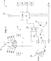
- Fig. 1 shows an arrangement provided in an agricultural tractor (not shown) for carrying out the method according to the invention.
- the arrangement 10 comprises a microprocessor-controlled control unit 12 as well as working hydraulics 14 which have a first control valve 16 that can be electrically actuated by the control unit 12 and a second control valve 18 that can be electrically actuated by the control unit 12.
- the two control valves 16, 18 combined in pairs in a common control device 20, which communicates to supply a hydraulic consumer 22 with hydraulic fluid with a hydraulic system 24 also provided in the agricultural tractor, which essentially consists of a hydraulic high-pressure pump 26 and a reservoir 28 for hydraulic fluid.
- the function of such a hydraulic system 24 is well known, so that a more detailed description will be dispensed with at this point.
- the control device 20 is also referred to in common parlance as SCV or Selective Control Valve.
- Each of the two control valves 16, 18 is assigned a releasable hydraulic coupling 30, 32 to which a complementary hydraulic coupler 34, 36 of a respective connecting hose 38, 40 of the hydraulic consumer 22 can be connected.
- the hydraulic couplings 30, 32 are generally structurally integrated into the control device 20.
- the hydraulic consumer 22 is part of an attachment 42 which is attached to a three-point power lift arranged in the rear area of the agricultural tractor. For the sake of clarity, the latter is in Fig. 1 not shown.
- the hydraulic consumer 22 is designed in the form of hydraulic drive units or actuating devices. Instead of a three-point power lift, however, it can also be any other coupling device for attaching an attachment, for example a hitch or a pick-up hitch.
- FIG. 1 Only a single control device 20 is shown; in fact, as a rule, a large number of other control devices of the same design are present, which are mounted in a stack one above the other in the rear region of the agricultural tractor.
- a branch 48 assigned to at least one of the control valves 16, 18 for supplying a hydraulic lifting mechanism 50 of a front linkage 52 with hydraulic fluid, as well as an operating unit 54 provided for manual actuation of the hydraulic lifting mechanism 50 of the front linkage 52.
- the junction 48 allows the hydraulic lifting mechanism 50, that is to say the two lifting cylinders 56, 58 of the front linkage 52, to be controlled hydraulically by using the existing control valve 16, 18. If the hydraulic lifting mechanism 50 has double-acting lifting cylinders 56, 58, such a branch is assigned to both control valves 16, 18 as an inlet or return, in the case of a single-acting lifting cylinder 56, 58 a single one is sufficient as an inlet.
- the operating unit 54 is a remote control 60 which is connected to the control unit 12 and has push buttons for raising and lowering the front linkage 52.
- the remote control 60 is attached in the area of the front linkage 52.
- Each of the two hydraulic couplings 30, 32 has a swiveling dust protection cover 62, 64, with a sensor unit 66, 68 detecting whether the dust protection cover 62, 64 is in a (closed) swivel position A that closes the associated hydraulic coupling 30, 32 or a Associated hydraulic coupling 30, 32 releasing (open) pivot position B is located.
- the sensor unit 66, 68 is in each case a magnetic switch which is actuated by a permanent magnet embedded in the associated dust protection cover 62, 64.
- the fact that the dust protection cover 62, 64 is in its open pivoted position B is a reliable indication that a hydraulic coupler 34, 36 and thus a connecting hose 38, 40 leading to a hydraulic consumer 22 of the attachment 42 is connected to the relevant hydraulic coupling 30 , 32 is connected.
- the pivot position detected by the sensor unit 66, 68 thus forms a state variable that indicates a plugged-in state of the hydraulic coupling 30, 32.
- the state variables provided by the two sensor units 66, 68 are fed to the control unit 12 for evaluation.
- a display unit 70, 72 that can be controlled by the control unit 12 and is used to identify a deactivation and / or blocking of the operating element 44, 46 provided for manual actuation of the control valve 16, 18.
- the display unit 70, 72 is a red light-emitting diode which is spatially directly assigned to the respective operating element 44, 46.
- shut-off valve 74 For the purpose of shutting down the front linkage 52, it is possible to interrupt the junction 48 in the direction of the hydraulic lifting mechanism 50 by means of a shut-off valve 74 comprised by the working hydraulics 14. Another sensor unit 76 is used to detect a valve position variable which indicates an opening state of the shut-off valve 74 and which is also fed to the control unit 12 for the purpose of evaluation. According to an optional embodiment of the working hydraulics 14, the shut-off valve 74 is designed to be electrically actuatable by the control unit 12.
- An information unit 78 communicating with the control unit 12 in the form of an OLED display enables additional information to be output to the driver.
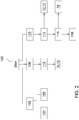
- FIG. 8 shows an exemplary embodiment of the method according to the invention for recognizing impermissible operating states of the working hydraulics 14 of the agricultural tractor, illustrated as a flow chart.
- control unit 12 The method carried out by the control unit 12 is started in an initialization step 100. Different functions are implemented here.
- a first step 102 an evaluation of the state variables detected by means of the sensor units 66, 68 takes place. If the result of ORing the state variables provided by the two sensor units 66, 68 is that one of the two dust protection covers 62, 64 is in its open pivot position B, the control unit 12 concludes that a hydraulic clutch 30, 32 is connected to the relevant hydraulic clutch 30, 32 Consumer 22 of an attachment 42 is connected. In order to avoid that an actuation of the hydraulic lifting mechanism 50 carried out via the operating unit 54 at the same time leads to undesired movements or deflections on the attachment 42, the operating unit 54 is deactivated by the control unit 12 in a second step 104.
- the operating unit 54 is released for the opposite case, in which the control unit 12, by evaluating the state variables provided by the two sensor units 66, 68, determines that both dust protection covers 62, 64 are in their closed pivot position A, thus actuating the front linkage 52 is permissible.
- shut-off valve 74 is designed to be electrically actuatable, it remains closed at the instigation of the control unit 12 as long as the evaluation of the detected state variables in the first step 102 shows that a hydraulic consumer 22 is connected to one of the hydraulic clutches 30, 32. As soon as both dust protection covers 62, 64 are brought into their closed pivot position A, the shut-off valve 74 of the control unit 12 is in a third Step 106 automatically opened. The switchover carried out in this way excludes an unconscious operator-side actuation of the front linkage 52 via the operating elements 44, 46 when the hydraulic consumer 22 is connected.
- the attachment 42 or the work function assigned to the corresponding hydraulic consumer 22 is thus prioritized.
- a fourth step 108 the state variables provided by the two sensor units 66, 68 are again evaluated. If it turns out that one of the two dust protection covers 62, 64 is in its closed pivot position A and the shut-off valve 74 is closed, the control unit 12 controls the operating element 44, 46 provided for manual actuation of the associated control valve 16, 18 in a fifth step 110 deactivated and / or blocked. At the same time, the control of the display unit 70, 72 spatially directly assigned to the relevant operating element 44, 46 takes place in order to visually signal the deactivation and / or blocking by means of the associated red light-emitting diode.
- a second additional function performed by the control unit 12 is provided.
- the valve position variable is evaluated in conjunction with the state variables provided by the two sensor units 66, 68. The result is that the shut-off valve 74 is open in the direction of the hydraulic lifting mechanism 50 of the front linkage 52 and at the same time one of the two dust protection covers 62, 64 is in its open pivot position B, and consequently a hydraulic consumer 22 is connected to the relevant hydraulic coupling 30, 32,
- the operating element 44, 46 provided for manual actuation of the associated control valve 16, 18 is deactivated and / or blocked by the control unit 12 in a seventh step 114.
- the control of the display unit 70, 72 spatially directly assigned to the control element 44, 46 takes place in the form of the respective red light-emitting diode, so that at the same time a visual signaling of the deactivation and / or blocking of the respective control element 44, 46 takes place.
- the control unit 12 Will be in one eighth step 116 recognizes a driver's intention to actuate the operating element 44, 46 and thus ultimately of the hydraulic consumer 22 connected to it, the control unit 12 initiates the output of a driver instruction via the information unit 78 that the shut-off valve 74 is to be closed.
- the operating element 44, 46 is released in a ninth step 118 and the control of the display unit 70, 72 is ended.
Landscapes
- Engineering & Computer Science (AREA)
- Life Sciences & Earth Sciences (AREA)
- Mechanical Engineering (AREA)
- Soil Sciences (AREA)
- Environmental Sciences (AREA)
- Physics & Mathematics (AREA)
- Fluid Mechanics (AREA)
- General Engineering & Computer Science (AREA)
- Lifting Devices For Agricultural Implements (AREA)
Abstract
Description
- Die Erfindung betrifft ein Verfahren zur Erkennung unzulässiger Betriebszustände einer Arbeitshydraulik eines landwirtschaftlichen Traktors. Die Arbeitshydraulik umfasst wenigstens ein elektrisch betätigbares Steuerventil mit einer Hydraulickupplung zum Anschließen eines hydraulischen Verbrauchers, eine dem wenigstes einen Steuerventil zugeordnete Abzweigung zur Versorgung eines hydraulischen Hubwerks eines Frontkrafthebers mit Hydraulikflüssigkeit sowie eine zur manuellen Betätigung des hydraulischen Hubwerks des Frontkrafthebers vorgesehene Bedieneinheit.
- Moderne landwirtschaftliche Traktoren erlauben es, unterschiedlichsten Arbeitsaufgaben im kommunalen, forst- und landwirtschaftlichen Bereich gerecht zu werden. Diese Vielseitigkeit wird insbesondere durch die Möglichkeit der Kombination mit einer Vielzahl verschiedener Anbaugeräte erreicht. Letztere lassen sich beispielsweise mittels eines im Front- und/oder Heckbereich des landwirtschaftlichen Traktors angeordneten Dreipunkt-Krafthebers anbringen. Je nach Anbaugerätetyp und ausgeführter Arbeitsfunktion kann das Anbaugerät über eigene hydraulische Verbraucher in Gestalt hydraulischer Antriebsaggregate bzw. Stelleinrichtungen verfügen. Diese werden seitens eines im landwirtschaftlichen Traktor vorgesehenen Hydrauliksystems mit Hydraulikflüssigkeit versorgt, wozu die hydraulischen Antriebsaggregate bzw. Stelleinrichtungen über Verbindungsschläuche an von zugehörigen Steuergeräten (SCVs - Selective Control Valves) umfasste Steuerventile am landwirtschaftlichen Traktor anschließbar sind, die sich ihrerseits mittels in einer Fahrerkabine bzw. Bedienkonsole untergebrachten Bedienelementen elektrisch betätigen lassen. Jedes der paarweise zur Bereitstellung eines Zu- und Rücklaufs in einem gemeinsamen Steuergerät zusammengefassten Steuerventile umfasst eine lösbare Hydraulikkupplung, an der sich ein komplementär ausgebildeter Hydraulikkuppler eines jeweiligen Verbindungsschlauchs des Anbaugeräts anschließen lässt.
- Häufig sind derartige Steuergeräte ausschließlich im Heckbereich des landwirtschaftlichen Traktors vorgesehen, nicht jedoch im Frontbereich. Soll der landwirtschaftliche Traktor daher mit einem Frontkraftheber aufgerüstet werden, erfolgt die hydraulische Ansteuerung des zugehörigen hydraulischen Hubwerks, also der beiden Hubzylinder des Frontkrafthebers, über eines der im Heckbereich befindlichen Steuergeräte. Zu diesem Zweck ist zumindest einem der Steuerventile des betreffenden Steuergeräts eine in Richtung des hydraulischen Hubwerks führende Abzweigung zugeordnet. Weist das hydraulische Hubwerk doppeltwirkende Hubzylinder auf, ist beiden Steuerventilen eine derartige Abzweigung als Zu- bzw. Rücklauf zugeordnet, im Falle eines einfachwirkenden Hubzylinders genügt eine einzelne als Zulauf.
- Ist an dem Hydraulikkuppler des zumindest einen Steuerventils zugleich ein hydraulisches Antriebsaggregat bzw. eine Stelleinrichtung eines Anbaugeräts angeschlossen, kann es im Falle einer Betätigung des hydraulischen Hubwerks zugleich zu unerwünschten Bewegungen bzw. Auslenkungen am Anbaugerät kommen.
- Es ist daher Aufgabe der vorliegenden Erfindung, ein Verfahren der eingangs genannten Art dahingehend anzugeben, dass im Falle eines für ein hydraulisches Hubwerk eines Frontkrafth ebers genutzten Steuerventils unerwünschte Bewegungen bzw. Auslenkungen an einem ebenfalls daran angeschlossenen Anbaugerät unterbleiben.
- Diese Aufgabe wird durch ein Verfahren mit den Merkmalen des Patentanspruchs 1 gelöst.
- Bei einem Verfahren zur Erkennung unzulässiger Betriebszustände einer Arbeitshydraulik eines landwirtschaftlichen Traktors umfasst die Arbeitshydraulik wenigstens ein elektrisch betätigbares Steuerventil mit einer Hydraulikkupplung zum Anschließen eines hydraulischen Verbrauchers, eine dem wenigstens einen Steuerventil zugeordnete Abzweigung zur Versorgung eines hydraulischen Hubwerks eines Frontkrafthebers mit Hydraulikflüssigkeit sowie eine zur manuellen Betätigung der Arbeitshydraulik des Frontkrafthebers vorgesehene Bedieneinheit. Erfindungsgemäß wird mittels einer Sensoreinheit eine auf einen Steckzustand der Hydraulikkupplung hinweisende Zustandsgröße erfasst und einer Kontrolleinheit zugeführt, wobei die Bedieneinheit deaktiviert wird, wenn von der Kontrolleinheit durch Auswertung der Zustandsgröße erkannt wird, dass an der Hydraulikkupplung ein hydraulischer Verbraucher angeschlossen ist.
- Auf diese Weise lässt sich vermeiden, dass eine über die Bedieneinheit vorgenommene Betätigung des hydraulischen Hubwerks zu unerwünschten Bewegungen bzw. Auslenkungen an einem an demselben Steuerventil angeschlossenen Anbaugerät führt.
- Bei der Bedieneinheit kann es sich um eine mit der Kontrolleinheit in Verbindung stehende Fernbedienung mit Tastschaltern zum Heben und Senken des Frontkrafthebers handeln, die im Bereich des Frontkrafthebers angebracht ist. In einem solchen Fall ist das erfindungsgemäße Verfahren von besonderem Vorteil, denn das im Heckbereich befindliche Anbaugerät ist beim Betätigen der im Frontbereich angeordneten Fernbedienung meist nicht einsehbar, sodass eine an diesem ausgelöste Aktion nicht oder vergleichsweise spät wahrgenommen werden dürfte.
- Vorteilhafte Ausgestaltungen des erfindungsgemäßen Verfahrens gehen aus den Unteransprüchen hervor.
- Vorzugsweise weist die Hydraulikkupplung einen schwenkbaren Staubschutzdeckel auf, wobei mittels der Sensoreinheit erfasst wird, ob sich der Staubschutzdeckel in einer die Hydraulickupplung verschließenden (geschlossenen) Schwenkstellung A oder einer die Hydraulikkupplung freigebenden (geöffneten) Schwenkstellung B befindet. Bei der Sensoreinheit kann es sich beispielsweise um einen robusten Magnetschalter handeln, der seitens eines in den Staubschutzdeckel eingebetteten Permanentmagneten betätigt wird. Der Umstand, dass sich der Staubschutzdeckel in seiner geöffneten Schwenkstellung B befindet, ist ein sicherer Hinweis darauf, dass ein Hydraulikkuppler und damit ein zu einem hydraulischen Verbraucher eines Anbaugeräts führender Verbindungsschlauch an der betreffenden Hydraulickupplung angeschlossen ist. Im Falle eines in einem gemeinsamen Steuergerät zusammengefassten Steuerventilpaars werden die von den Sensoreinheiten der zugehörigen beiden Staubschutzdeckel bereitgestellten Zustandsgrößen von der Kontrolleinheit miteinander ODER-verknüpft, sodass die Bedieneinheit bereits dann deaktiviert wird, wenn sich einer der beiden Staubschutzdeckel in seiner geöffneten Schwenkstellung B befindet. Um sicherzustellen, dass sich der Staubschutzdeckel bei unbenutztem Hydraulikkuppler tatsächlich in seiner geschlossenen Schwenkstellung A befindet, kann dieser mit einem Schließmechanismus in Form einer Rückstellfeder oder dergleichen versehen sein.
- Des Weiteren besteht die Möglichkeit, dass von der Kontrolleinheit ein zur manuellen Betätigung des wenigstens einen Steuerventils vorgesehenes Bedienelement in Abhängigkeit der erfassten Zustandsgröße deaktiviert und/oder gesperrt wird. Typischerweise ist das Bedienelement in Gestalt eines Tastschalters (sog. Paddle Pot Switch) in einer Bedienkonsole des landwirtschaftlichen Traktors untergebracht. Die Deaktivierung und/oder Sperrung wird von der Kontrolleinheit insbesondere dann vorgenommen, wenn sich aufgrund der erfassten Zustandsgröße ergibt, dass an der Hydraulikkupplung des zugehörigen Steuerventils kein hydraulischer Verbraucher angeschlossen ist, mithin das Bedienelement funktionslos ist. Dies trifft im Allgemeinen dann zu, wenn sich der Staubschutzdeckel des wenigstens einen Steuerventils in seiner geschlossenen Schwenkstellung A befindet. Hierdurch lässt sich eine über das funktionslose Bedienelement veranlasste Beaufschlagung des geschlossenen Hydraulikkupplers mit unter Druck stehender Hydraulikflüssigkeit unterbinden. Wird im Falle eines in einem gemeinsamen Steuergerät zusammengefassten Steuerventilpaars lediglich eines der Steuerventile zum Betrieb eines einfachwirkenden hydraulischen Verbrauchers verwendet, erfolgt eine Deaktivierung und/oder Sperrung lediglich des dem nicht genutzten Steuerventil zugeordneten Bedienelements. Dies kann auch vom Vorhandensein eines in der Abzweigung in Richtung des hydraulischen Hubwerks des Frontkrafthebers vorhandenen Absperrventils abhängig gemacht werden, wobei das Bedienelement ausschließlich bei geschlossenem Absperrventil deaktiviert bzw. gesperrt und ansonsten freigeben wird, sodass eine Ansteuerung des Frontkrafthebers über das betreffende Bedienelement möglich bleibt.
- Daneben ist es vorstellbar, dass von der Kontrolleinheit eine Anzeigeeinheit in Abhängigkeit der erfassten Zustandsgröße angesteuert wird, insbesondere um eine Deaktivierung und/oder Sperrung eines zur manuellen Betätigung des wenigstens einen Steuerventils vorgesehenen Bedienelements kenntlich zu machen. Bei der Anzeigeeinheit kann es sich beispielsweise um eine rote Leuchtdiode handeln, die räumlich unmittelbar dem Bedienelement zugeordnet ist. Zusätzlich kann die Anzeigeeinheit auch eine grüne Leuchtdiode umfassen, deren Ansteuerung dann im Falle einer Freigabe des Bedienelements anstelle der roten Leuchtdiode erfolgt.
- Für Zwecke der Außerbetriebnahme des Frontkrafthebers ist es möglich, dass die Abzweigung in Richtung des hydraulischen Hubwerks mittels eines Absperrventils unterbrochen werden kann. Dies ist unter anderem dann von Belang, wenn ein mögliches leckagebedingtes Absacken des Frontkrafthebers bei Transportfahrten oder dergleichen vermieden werden soll, oder aber, um das wenigstens eine Steuerventil auf den Betrieb eines daran angeschlossenen hydraulischen Verbrauchers einschränken zu können.
- Hierbei kann vorgesehen sein, dass mittels einer weiteren Sensoreinheit eine auf einen Öffnungszustand des Absperrventils hinweisende Ventilstellungsgröße erfasst wird, wobei ein zur manuellen Betätigung des wenigstens einen Steuerventils vorgesehenes Bedienelement in Abhängigkeit der erfassten Ventilstellungsgröße deaktiviert und/oder gesperrt wird. Dies kann dann erfolgen, wenn von der Kontrolleinheit durch Auswertung der Ventilstellungsgröße in Verbindung mit der mittels der Sensoreinheit erfassten Zustandsgröße erkannt wird, dass das Absperrventil in Richtung des hydraulischen Hubwerks des Frontkrafthebers geöffnet und zugleich an der Hydraulikkupplung des wenigstens einen Steuerventils ein hydraulischer Verbraucher angeschlossen ist, was von der Kontrolleinheit insbesondere aufgrund eines in seiner geöffneten Schwenkstellung B befindlichen Staubschutzdeckels erkannt werden kann. Hierdurch lässt sich eine versehentlich über das Bedienelement mitausgelöste Betätigung des hydraulischen Hubwerks des Frontkrafthebers unterbinden. Zusätzlich kann der Bediener durch Ausgabe eines entsprechenden Hinweises über eine Informationseinheit dazu aufgefordert werden, das Absperrventil zu schließen, sodass das Bedienelement zur Betätigung des hydraulischen Verbrauchers gefahrlos freigegeben werden kann.
- Das Absperrventil kann zusätzlich elektrisch betätigbar ausgebildet sein, wobei das Absperrventil auf Veranlassung der Kontrolleinheit solange geschlossen bleibt, wie sich durch Auswertung der erfassten Zustandsgröße ergibt, dass an der Hydraulikkupplung des wenigstens einen Steuerventils ein hydraulischer Verbraucher angeschlossen ist. Letzteres kann von der Kontrolleinheit aufgrund eines in seiner geöffneten Schwenkstellung B befindlichen Staubschutzdeckels erkannt werden. Sobald der Staubschutzdeckel in seine geschlossene Schwenkstellung A verbracht wird, wird das Absperrventil von der Kontrolleinheit selbsttätig geöffnet. Die solchermaßen vorgenommene Umschaltung schließt bei angeschlossenem hydraulischen Verbraucher eine unbewusste bedienerseitige Betätigung des Frontkrafthebers über das dem wenigstens einen Steuerventil zugeordnete Bedienelement von vornherein aus.
- Das erfindungsgemäße Verfahren zur Erkennung unzulässiger Betriebszustände einer Arbeitshydraulik eines landwirtschaftlichen Traktors wird im Folgenden anhand der beigefügten Zeichnungen näher erläutert. Hierbei sind übereinstimmende bzw. bezüglich ihrer Funktion vergleichbare Komponenten mit denselben Bezugszeichen gekennzeichnet. Es zeigen:
- Fig. 1
- eine schematisch dargestellte Anordnung zur Ausführung des erfindungsgemäßen Verfahrens, und
- Fig. 2
- ein das erfindungsgemäße Verfahren beispielhaft veranschaulichendes Flussdiagramm.
-
Fig. 1 zeigt eine in einem nicht dargestellten landwirtschaftlichen Traktor vorgesehene Anordnung zur Ausführung des erfindungsgemäßen Verfahrens. - Die Anordnung 10 umfasst eine mikroprozessorgesteuerte Kontrolleinheit 12 sowie eine Arbeitshydraulik 14, die ein von der Kontrolleinheit 12 elektrisch betätigbares erstes Steuerventil 16 sowie ein von der Kontrolleinheit 12 elektrisch betätigbares zweites Steuerventil 18 aufweist. Zur Bereitstellung eines Zu- und Rücklaufs sind die beiden Steuerventil 16, 18 paarweise in einem gemeinsamen Steuergerät 20 zusammengefasst, der zur Versorgung eines hydraulischen Verbrauchers 22 mit Hydraulikflüssigkeit mit einem in dem landwirtschaftlichen Traktor ebenfalls vorgesehenen Hydrauliksystem 24 kommuniziert, das im Wesentlichen aus einer hydraulischen Hochdruckpumpe 26 sowie einem Reservoir 28 für Hydraulikflüssigkeit besteht. Die Funktion eines derartigen Hydrauliksystems 24 ist hinlänglich bekannt, sodass an dieser Stelle auf eine weitergehende Beschreibung verzichtet werden soll. Das Steuergerät 20 wird im allgemeinen Sprachgebrauch auch als SCV oder Selective Control Valve bezeichnet.
- Jedem der beiden Steuerventile 16, 18 ist eine lösbare Hydraulikkupplung 30, 32 zugeordnet, an der sich ein komplementär ausgebildeter Hydraulikkuppler 34, 36 eines jeweiligen Verbindungsschlauchs 38, 40 des hydraulischen Verbrauchers 22 anschließen lässt. Abweichend von der Darstellung in
Fig. 1 sind die Hydraulikkupplungen 30, 32 im Allgemeinen baulich in das Steuergerät 20 integriert. - Der hydraulische Verbraucher 22 ist Bestandteil eines Anbaugeräts 42, das an einem im Heckbereich des landwirtschaftlichen Traktors angeordneten Dreipunkt-Kraftheber angebracht ist. Letzterer ist aus Gründen der Übersichtlichkeit in
Fig. 1 nicht dargestellt. Je nach Anbaugerätetyp und ausgeführter Arbeitsfunktion ist der hydraulische Verbraucher 22 in Gestalt hydraulischer Antriebsaggregate bzw. Stelleinrichtungen ausgebildet. Anstelle eines Dreipunkt-Krafthebers kann es sich jedoch auch um eine beliebige anderer Kupplungseinrichtung zur Anbringung eines Anbaugeräts handeln, so zum Beispiel ein Zugmaul oder eine Pick-Up Hitch. - Eine mit der Kontrolleinheit 12 kommunizierende Anordnung zweier Bedienelemente 44, 46, die in einer Fahrerkabine bzw. Bedienkonsole des landwirtschaftlichen Traktors untergebracht und als Tastschalter (sog. Paddle Pod Switches) ausgebildet sind, erlaubt eine manuelle Betätigung der beiden Steuerventile 16, 18 seitens eines Fahrers zur Ausführung der dem hydraulischen Verbraucher 22 zugeordneten Arbeitsfunktion.
- Stellvertretend ist in
Fig. 1 lediglich ein einzelnes Steuergerät 20 dargestellt, tatsächlich sind in der Regel eine Vielzahl weiterer gleichartig ausgestalteter Steuergeräte vorhanden, die in einem Stapel übereinanderliegend im Heckbereich des landwirtschaftlichen Traktors montiert sind. - Des Weiteren ist eine wenigstens einem der Steuerventile 16, 18 zugeordnete Abzweigung 48 zur Versorgung eines hydraulischen Hubwerks 50 eines Frontkrafthebers 52 mit Hydraulikflüssigkeit sowie eine zur manuellen Betätigung des hydraulischen Hubwerks 50 des Frontkrafthebers 52 vorgesehene Bedieneinheit 54 vorhanden. Die Abzweigung 48 erlaubt es, das hydraulische Hubwerk 50, also die beiden Hubzylinder 56, 58 des Frontkrafthebers 52, durch Nutzung des vorhandenen Steuerventils 16, 18 hydraulisch anzusteuern. Weist das hydraulische Hubwerk 50 doppeltwirkende Hubzylinder 56, 58 auf, ist beiden Steuerventilen 16, 18 eine derartige Abzweigung als Zu- bzw. Rücklauf zugeordnet, im Falle eines einfachwirkenden Hubzylinders 56, 58 genügt eine einzelne als Zulauf.
- Bei der Bedieneinheit 54 handelt es sich um eine mit der Kontrolleinheit 12 in Verbindung stehende Fernbedienung 60 mit Tastschaltern zum Heben und Senken des Frontkrafthebers 52. Die Fernbedienung 60 ist im Bereich des Frontkrafthebers 52 angebracht.
- Jede der beiden Hydraulikkupplungen 30, 32 weist einen schwenkbaren Staubschutzdeckel 62, 64 auf, wobei mittels einer Sensoreinheit 66, 68 erfasst wird, ob sich der Staubschutzdeckel 62, 64 in einer die zugehörige Hydraulikkupplung 30, 32 verschließenden (geschlossenen) Schwenkstellung A oder einer die zugehörige Hydraulikkupplung 30, 32 freigebenden (geöffneten) Schwenkstellung B befindet. Bei der Sensoreinheit 66, 68 handelt es sich jeweils um einen Magnetschalter, der seitens eines in den zugehörigen Staubschutzdeckel 62, 64 eingebetteten Permanentmagneten betätigt wird. Der Umstand, dass sich der Staubschutzdeckel 62, 64 in seiner geöffneten Schwenkstellung B befindet, ist ein sicherer Hinweis darauf, dass ein Hydraulikkuppler 34, 36 und damit ein zu einem hydraulischen Verbraucher 22 des Anbaugeräts 42 führender Verbindungsschlauch 38, 40 an der betreffenden Hydraulikkupplung 30, 32 angeschlossen ist. Die von der Sensoreinheit 66, 68 erfasste Schwenkstellung bildet somit eine auf einen Steckzustand der Hydraulikkupplung 30, 32 hinweisende Zustandsgröße. Die von den beiden Sensoreinheiten 66, 68 bereitgestellten Zustandsgrößen werden der Kontrolleinheit 12 zur Auswertung zugeführt.
- Daneben ist eine von der Kontrolleinheit 12 ansteuerbare Anzeigeeinheit 70, 72 vorhanden, die der Kenntlichmachung einer Deaktivierung und/oder Sperrung des zur manuellen Betätigung des Steuerventils 16, 18 vorgesehenen Bedienelements 44, 46 dient. Bei der Anzeigeeinheit 70, 72 handelt es sich um eine rote Leuchtdiode, die räumlich unmittelbar dem jeweiligen Bedienelement 44, 46 zugeordnet ist.
- Für Zwecke der Außerbetriebnahme des Frontkrafthebers 52 ist es möglich, die Abzweigung 48 in Richtung des hydraulischen Hubwerks 50 mittels eines von der Arbeitshydraulik 14 umfassten Absperrventils 74 zu unterbrechen. Eine weitere Sensoreinheit 76 dient der Erfassung einer auf einen Öffnungszustand des Absperrventils 74 hinweisenden Ventilstellungsgröße, die der Kontrolleinheit 12 ebenfalls zum Zwecke der Auswertung zugeführt wird. Gemäß einer optionalen Ausgestaltung der Arbeitshydraulik 14 ist das Absperrventil 74 seitens der Kontrolleinheit 12 elektrisch betätigbar ausgebildet.
- Eine mit der Kontrolleinheit 12 kommunizierende Informationseinheit 78 in Gestalt eines OLED-Displays ermöglicht die Ausgabe von zusätzlichen Hinweisen an den Fahrer.
-
Fig. 2 zeigt ein als Flussdiagramm veranschaulichtes Ausführungsbeispiel des erfindungsgemäßen Verfahrens zur Erkennung unzulässiger Betriebszustände der Arbeitshydraulik 14 des landwirtschaftlichen Traktors. - Das von der Kontrolleinheit 12 ausgeführte Verfahren wird in einem Initialisierungsschritt 100 gestartet. Hierbei sind unterschiedliche Funktionen verwirklicht.
- Gemäß einer von der Kontrolleinheit 12 ausgeführten Basisfunktion erfolgt in einem ersten Schritt 102 zunächst eine Auswertung der mittels der Sensoreinheiten 66, 68 erfassten Zustandsgrößen. Ergibt sich durch ODER-Verknüpfung der von den beiden Sensoreinheiten 66, 68 bereitgestellten Zustandsgrößen, dass sich einer der beiden Staubschutzdeckel 62, 64 in seiner geöffneten Schwenkstellung B befindet, so schließt die Kontrolleinheit 12 darauf, dass an der betreffenden Hydraulickupplung 30, 32 ein hydraulischer Verbraucher 22 eines Anbaugeräts 42 angeschlossen ist. Um zu vermeiden, dass eine über die Bedieneinheit 54 vorgenommene Betätigung des hydraulischen Hubwerks 50 daher zugleich zu unerwünschten Bewegungen bzw. Auslenkungen am Anbaugerät 42 führt, wird die Bedieneinheit 54 von der Kontrolleinheit 12 in einem zweiten Schritt 104 deaktiviert. Dementsprechend erfolgt eine Freigabe der Bedieneinheit 54 für den umgekehrten Fall, in dem die Kontrolleinheit 12 durch Auswertung der von den beiden Sensoreinheiten 66, 68 bereitgestellten Zustandsgrößen feststellt, dass beide Staubschutzdeckel 62, 64 sich in ihrer geschlossenen Schenkstellung A befinden, mithin eine Betätigung des Frontkrafthebers 52 zulässig ist.
- Ist das Absperrventil 74 elektrisch betätigbar ausgebildet, bleibt dieses auf Veranlassung der Kontrolleinheit 12 solange geschlossen, wie sich durch Auswertung der erfassten Zustandsgrößen im ersten Schritt 102 ergibt, dass an einer der Hydraulikkupplungen 30, 32 ein hydraulischer Verbraucher 22 angeschlossen ist. Sobald beide Staubschutzdeckel 62, 64 in ihre geschlossene Schwenkstellung A verbracht werden, wird das Absperrventil 74 von der Kontrolleinheit 12 in einem dritten Schritt 106 selbsttätig geöffnet. Die solchermaßen vorgenommene Umschaltung schließt bei angeschlossenem hydraulischen Verbraucher 22 eine unbewusste bedienerseitige Betätigung des Frontkrafthebers 52 über die Bedienelemente 44, 46 aus.
- Es erfolgt somit eine Priorisierung des Anbaugeräts 42 bzw. der dem entsprechenden hydraulischen Verbraucher 22 zugeordneten Arbeitsfunktion.
- Gemäß einer von der Kontrolleinheit 12 ausgeführten ersten Zusatzfunktion erfolgt in einem vierten Schritt 108 erneut eine Auswertung der von den beiden Sensoreinheiten 66, 68 bereitgestellten Zustandsgrößen. Ergibt sich, dass sich einer der beiden Staubschutzdeckel 62, 64 in seiner geschlossenen Schwenkstellung A befindet und das Absperrventil 74 geschlossen ist, wird von der Kontrolleinheit 12 das zur manuellen Betätigung des zugehörigen Steuerventils 16, 18 vorgesehene Bedienelement 44, 46 in einem fünften Schritt 110 deaktiviert und/oder gesperrt. Zugleich erfolgt die Ansteuerung der dem betreffenden Bedienelement 44, 46 räumlich unmittelbar zugeordneten Anzeigeeinheit 70, 72, um die Deaktivierung und/oder Sperrung mittels der zugehörigen roten Leuchtdiode visuell zu signalisieren. Hierdurch lässt sich eine über das funktionslose Bedienelement 44, 46 veranlasste Beaufschlagung des geschlossenen Hydraulikkupplers 30, 32 mit unter Druck stehender Hydraulikflüssigkeit unterbinden. Wird lediglich eines der Steuerventile 16, 18 zum Betrieb eines einfachwirkenden hydraulischen Verbrauchers 22 verwendet, erfolgt eine Deaktivierung und/oder Sperrung lediglich des dem nicht genutzten Steuerventil 16, 18 zugeordneten Bedienelements 44, 46. Dies kann von dem durch die erfasste Ventilstellungsgröße repräsentierten Öffnungszustand des Absperrventils 48 abhängig gemacht werden, wobei das Bedienelement 44, 46 ausschließlich bei geschlossenem Absperrventil 48 deaktiviert bzw. gesperrt und ansonsten freigeben wird, sodass eine Ansteuerung des Frontkrafthebers 52 über das betreffende Bedienelement 44, 46 möglich bleibt.
- Daneben ist eine von der Kontrolleinheit 12 ausgeführte zweite Zusatzfunktion vorgesehen. Bei dieser erfolgt in einem sechsten Schritt 112 eine Auswertung der Ventilstellungsgröße in Verbindung mit den seitens der beiden Sensoreinheiten 66, 68 bereitgestellten Zustandsgrößen. Ergibt sich, dass das Absperrventil 74 in Richtung des hydraulischen Hubwerks 50 des Frontkrafthebers 52 geöffnet ist und sich zugleich einer der beiden Staubschutzdeckel 62, 64 in seiner geöffneten Schwenkstellung B befindet, mithin an der betreffenden Hydraulikkupplung 30, 32 ein hydraulischer Verbraucher 22 angeschlossen ist, so wird das zur manuellen Betätigung des zugehörigen Steuerventils 16, 18 vorgesehene Bedienelement 44, 46 von der Kontrolleinheit 12 in einem siebten Schritt 114 deaktiviert und/oder gesperrt. Hierdurch lässt sich eine versehentlich über das Bedienelement 44, 46 mitausgelöste Betätigung des hydraulischen Hubwerks 50 des Frontkrafthebers 52 unterbinden. Zusätzlich erfolgt die Ansteuerung der dem Bedienelement 44, 46 räumlich unmittelbar zugeordneten Anzeigeeinheit 70, 72 in Gestalt der jeweiligen roten Leuchtdiode, sodass zugleich eine visuelle Signalisierung der Deaktivierung und/oder Sperrung des betreffenden Bedienelements 44, 46 erfolgt. Wird in einem achten Schritt 116 eine fahrerseitige Betätigungsabsicht des Bedienelements 44, 46 und damit letztlich des daran angeschlossenen hydraulischen Verbrauchers 22 erkannt, so veranlasst die Kontrolleinheit 12 über die Informationseinheit 78 die Ausgabe eines Fahrerhinweises, dass das Absperrventil 74 zu schließen ist. Sobald dies geschehen ist, wird das Bedienelement 44, 46 in einem neunten Schritt 118 freigegeben sowie die Ansteuerung der Anzeigeeinheit 70, 72 beendet.
Claims (7)
- Verfahren zur Erkennung unzulässiger Betriebszustände einer Arbeitshydraulik eines landwirtschaftlichen Traktors, bei dem die Arbeitshydraulik (14) wenigstens ein elektrisch betätigbares Steuerventil (16, 18) mit einer Hydraulikkupplung (30, 32) zum Anschließen eines hydraulischen Verbrauchers (22), eine dem wenigstens einen Steuerventil (16, 18) zugeordnete Abzweigung (48) zur Versorgung eines hydraulischen Hubwerks (50) eines Frontkrafthebers (52) mit Hydraulikflüssigkeit sowie eine zur manuellen Betätigung der Arbeitshydraulik (14) des Frontkrafthebers (52) vorgesehene Bedieneinheit (54) umfasst, dadurch gekennzeichnet, dass mittels einer Sensoreinheit (66, 68) eine auf einen Steckzustand der Hydraulikkupplung (30, 32) hinweisende Zustandsgröße erfasst und einer Kontrolleinheit (12) zugeführt wird, wobei die Bedieneinheit (54) deaktiviert wird, wenn von der Kontrolleinheit (12) durch Auswertung der Zustandsgröße erkannt wird, dass an der Hydraulikkupplung (30, 32) ein hydraulischer Verbraucher (22) angeschlossen ist.
- Verfahren nach Anspruch 1, dadurch gekennzeichnet, dass die Hydraulikkupplung (30, 32) einen schwenkbaren Staubschutzdeckel (62, 64) aufweist, wobei mittels der Sensoreinheit (66, 68) erfasst wird, ob sich der Staubschutzdeckel (62, 64) in einer die Hydraulikkupplung (30, 32) verschließenden Schwenkstellung (A) oder einer die Hydraulikkupplung (30, 32) freigebenden Schwenkstellung (B) befindet.
- Verfahren nach Anspruch 1 oder 2, dadurch gekennzeichnet, dass von der Kontrolleinheit (12) ein zur manuellen Betätigung des wenigstens einen Steuerventils (16, 18) vorgesehenes Bedienelement (44, 46) in Abhängigkeit der erfassten Zustandsgröße deaktiviert und/oder gesperrt wird.
- Verfahren nach wenigstens einem der Ansprüche 1 bis 3, dadurch gekennzeichnet, dass von der Kontrolleinheit (12) eine Anzeigeeinheit (70, 72) in Abhängigkeit der erfassten Zustandsgröße angesteuert wird.
- Verfahren nach wenigstens einem der Ansprüche 1 bis 4, dadurch gekennzeichnet, dass die Abzweigung (48) in Richtung des hydraulischen Hubwerks (50) mittels eines Absperrventils (74) unterbrochen werden kann.
- Verfahren nach Anspruch 5, dadurch gekennzeichnet, dass mittels einer weiteren Sensoreinheit (76) eine auf einen Öffnungszustand des Absperrventils (74) hinweisende Ventilstellungsgröße erfasst wird, wobei ein zur manuellen Betätigung des wenigstens einen Steuerventils (16, 18) vorgesehenes Bedienelement (44, 46) in Abhängigkeit der erfassten Ventilstellungsgröße deaktiviert und/oder gesperrt wird.
- Verfahren nach Anspruch 5 oder 6, dadurch gekennzeichnet, dass das Absperrventil (74) elektrisch betätigbar ausgebildet ist, wobei das Absperrventil (74) auf Veranlassung der Kontrolleinheit (12) solange geschlossen bleibt, wie sich durch Auswertung der erfassten Zustandsgröße ergibt, dass an der Hydraulikkupplung (30, 32) des wenigstens einen Steuerventils (16, 18) ein hydraulischer Verbraucher (22) angeschlossen ist.
Applications Claiming Priority (1)
| Application Number | Priority Date | Filing Date | Title |
|---|---|---|---|
| DE102019214228.1A DE102019214228A1 (de) | 2019-09-18 | 2019-09-18 | Verfahren zur Erkennung unzulässiger Betriebszustände einer Arbeitshydraulik eines landwirtschaftlichen Traktors |
Publications (2)
| Publication Number | Publication Date |
|---|---|
| EP3794917A1 true EP3794917A1 (de) | 2021-03-24 |
| EP3794917B1 EP3794917B1 (de) | 2022-08-10 |
Family
ID=72292294
Family Applications (1)
| Application Number | Title | Priority Date | Filing Date |
|---|---|---|---|
| EP20193514.5A Active EP3794917B1 (de) | 2019-09-18 | 2020-08-31 | Verfahren zur erkennung unzulässiger betriebszustände einer arbeitshydraulik eines landwirtschaftlichen traktors |
Country Status (3)
| Country | Link |
|---|---|
| US (1) | US11589493B2 (de) |
| EP (1) | EP3794917B1 (de) |
| DE (1) | DE102019214228A1 (de) |
Families Citing this family (1)
| Publication number | Priority date | Publication date | Assignee | Title |
|---|---|---|---|---|
| US12211333B1 (en) * | 2022-12-16 | 2025-01-28 | Amazon Technologies, Inc. | Protective coverings for displays used in outdoor environments |
Citations (2)
| Publication number | Priority date | Publication date | Assignee | Title |
|---|---|---|---|---|
| DE10304377B3 (de) * | 2003-02-04 | 2004-04-01 | CNH Österreich GmbH | Anordnung und Verfahren zur Steuerung eines Hubwerkes eines landwirtschaftlichen Nutzfahrzeuges |
| DE102010034613A1 (de) * | 2010-08-18 | 2012-02-23 | Robert Bosch Gmbh | Landwirtschaftliche Arbeitsmaschine |
Family Cites Families (6)
| Publication number | Priority date | Publication date | Assignee | Title |
|---|---|---|---|---|
| DE263843C (de) * | ||||
| DE3441946A1 (de) * | 1984-11-16 | 1986-05-28 | Robert Bosch Gmbh, 7000 Stuttgart | Hydraulische steuereinrichtung |
| DD263843A1 (de) * | 1987-06-01 | 1989-01-11 | Schwermasch Nobas Veb | Verfahren zur leistungsregelung von maschinen oder technologischen einrichtungen |
| DE102006004423B4 (de) * | 2006-01-31 | 2018-08-02 | Robert Bosch Gmbh | Ventilanordnung zur Ansteuerung eines Hubwerkes oder Anbaugerätes sowie Verfahren zur Ansteuerung dieser |
| JP5860711B2 (ja) * | 2012-02-03 | 2016-02-16 | Kyb株式会社 | 流体圧制御装置 |
| JP6190916B1 (ja) * | 2016-04-28 | 2017-08-30 | Kyb株式会社 | 作業機の昇降制御装置 |
-
2019
- 2019-09-18 DE DE102019214228.1A patent/DE102019214228A1/de not_active Withdrawn
-
2020
- 2020-08-05 US US16/985,389 patent/US11589493B2/en active Active
- 2020-08-31 EP EP20193514.5A patent/EP3794917B1/de active Active
Patent Citations (2)
| Publication number | Priority date | Publication date | Assignee | Title |
|---|---|---|---|---|
| DE10304377B3 (de) * | 2003-02-04 | 2004-04-01 | CNH Österreich GmbH | Anordnung und Verfahren zur Steuerung eines Hubwerkes eines landwirtschaftlichen Nutzfahrzeuges |
| DE102010034613A1 (de) * | 2010-08-18 | 2012-02-23 | Robert Bosch Gmbh | Landwirtschaftliche Arbeitsmaschine |
Also Published As
| Publication number | Publication date |
|---|---|
| EP3794917B1 (de) | 2022-08-10 |
| DE102019214228A1 (de) | 2021-03-18 |
| US20210076555A1 (en) | 2021-03-18 |
| US11589493B2 (en) | 2023-02-28 |
Similar Documents
| Publication | Publication Date | Title |
|---|---|---|
| DE112012001637B4 (de) | Arbeitsfahrzeug und Steuerverfahren für das Arbeitsfahrzeug | |
| DE112013000129B4 (de) | Arbeitsfahrzeug und Verfahren zum Steuern des Arbeitsfahrzeugs | |
| EP0714592B1 (de) | Steuersystem zur Lageeinstellung von Anhängevorrichtungen | |
| DE102004028437B3 (de) | Ventilanordnung | |
| EP1584756B1 (de) | Aktivierungssystem für eine Gerätesteuereinrichtung | |
| EP2116120B1 (de) | Verfahren zum Betrieben einer Steuerung für eine TRaktorgerätekombination mit wenigstens einer auswechselbare Ausrüstung | |
| DE102018132105A1 (de) | System zum betreiben eines drehkranzantriebs einer maschine | |
| DE10138389A1 (de) | Elektrohydraulische Einrichtung zur Steuerung eines doppelt wirkenden Motors | |
| EP3794917B1 (de) | Verfahren zur erkennung unzulässiger betriebszustände einer arbeitshydraulik eines landwirtschaftlichen traktors | |
| EP3400769B1 (de) | Landwirtschaftliche arbeitsmaschine sowie verfahren zum betreiben einer landwirtschaftlichen arbeitsmaschine | |
| DE10336684A1 (de) | Hydraulische Steueranordnung für eine mobile Arbeitsmaschine | |
| EP3443828B1 (de) | Hydraulische druckmittelversorgung und adapterventileinheit | |
| DE102022126034A1 (de) | Ventilanordnung für Arbeitsmaschinen mit ölhydraulischem Werkzeug | |
| EP3436705B1 (de) | Steuervorrichtung | |
| DE102011101714A1 (de) | Verfahren einer elektrohydraulischen Hubwerksregelung und Bedieneinheit für eine elektrohydraulische Hubwerksregelung | |
| EP4237926A1 (de) | Steuerverfahren für einen zur bedienung einer betriebs- und/oder arbeitsfunktion vorgesehenen handbedienhebel | |
| EP0607603B1 (de) | Arbeitsgerät mit wenigstens zwei Sätzen von Arbeitswerkzeugen | |
| DE102007040345A1 (de) | Verfahren zum Ansteuern eines Hubwerks und Hubwerk | |
| EP3653033B1 (de) | Verfahren zum betreiben einer zapfwelle eines landwirtschaftlichen traktors mit einem anbaugerätehubwerk | |
| EP3632755B1 (de) | Fahrzeug und zuggespann | |
| DE19942504A1 (de) | Einrichtung zum Wenden eines an einem landwirtschaftlichen Fahrzeug angelenkten Anbaugeräts, insbesondere eines Drehpfluges | |
| DE102022111489A1 (de) | Hydraulische Verstellvorrichtung | |
| EP1031263B2 (de) | Vorrichtung und Verfahren zur Eingabe von Arbeitsparametern an landwirtschaftlichen Maschinen | |
| EP1622443B1 (de) | Anordnung und verfahren zur steuerung eines hubwerkes eines landwirtschaftlichen nutzfahrzeuges | |
| DE102015224747A1 (de) | Feldrandbereich-betriebssteuerungssystem |
Legal Events
| Date | Code | Title | Description |
|---|---|---|---|
| PUAI | Public reference made under article 153(3) epc to a published international application that has entered the european phase |
Free format text: ORIGINAL CODE: 0009012 |
|
| STAA | Information on the status of an ep patent application or granted ep patent |
Free format text: STATUS: THE APPLICATION HAS BEEN PUBLISHED |
|
| AK | Designated contracting states |
Kind code of ref document: A1 Designated state(s): AL AT BE BG CH CY CZ DE DK EE ES FI FR GB GR HR HU IE IS IT LI LT LU LV MC MK MT NL NO PL PT RO RS SE SI SK SM TR |
|
| AX | Request for extension of the european patent |
Extension state: BA ME |
|
| STAA | Information on the status of an ep patent application or granted ep patent |
Free format text: STATUS: REQUEST FOR EXAMINATION WAS MADE |
|
| 17P | Request for examination filed |
Effective date: 20210924 |
|
| RBV | Designated contracting states (corrected) |
Designated state(s): AL AT BE BG CH CY CZ DE DK EE ES FI FR GB GR HR HU IE IS IT LI LT LU LV MC MK MT NL NO PL PT RO RS SE SI SK SM TR |
|
| GRAP | Despatch of communication of intention to grant a patent |
Free format text: ORIGINAL CODE: EPIDOSNIGR1 |
|
| STAA | Information on the status of an ep patent application or granted ep patent |
Free format text: STATUS: GRANT OF PATENT IS INTENDED |
|
| INTG | Intention to grant announced |
Effective date: 20220324 |
|
| GRAS | Grant fee paid |
Free format text: ORIGINAL CODE: EPIDOSNIGR3 |
|
| GRAA | (expected) grant |
Free format text: ORIGINAL CODE: 0009210 |
|
| STAA | Information on the status of an ep patent application or granted ep patent |
Free format text: STATUS: THE PATENT HAS BEEN GRANTED |
|
| AK | Designated contracting states |
Kind code of ref document: B1 Designated state(s): AL AT BE BG CH CY CZ DE DK EE ES FI FR GB GR HR HU IE IS IT LI LT LU LV MC MK MT NL NO PL PT RO RS SE SI SK SM TR |
|
| REG | Reference to a national code |
Ref country code: AT Ref legal event code: REF Ref document number: 1509813 Country of ref document: AT Kind code of ref document: T Effective date: 20220815 Ref country code: CH Ref legal event code: EP |
|
| REG | Reference to a national code |
Ref country code: DE Ref legal event code: R096 Ref document number: 502020001502 Country of ref document: DE |
|
| REG | Reference to a national code |
Ref country code: IE Ref legal event code: FG4D Free format text: LANGUAGE OF EP DOCUMENT: GERMAN |
|
| REG | Reference to a national code |
Ref country code: NL Ref legal event code: MP Effective date: 20220810 |
|
| REG | Reference to a national code |
Ref country code: LT Ref legal event code: MG9D |
|
| PG25 | Lapsed in a contracting state [announced via postgrant information from national office to epo] |
Ref country code: SE Free format text: LAPSE BECAUSE OF FAILURE TO SUBMIT A TRANSLATION OF THE DESCRIPTION OR TO PAY THE FEE WITHIN THE PRESCRIBED TIME-LIMIT Effective date: 20220810 Ref country code: RS Free format text: LAPSE BECAUSE OF FAILURE TO SUBMIT A TRANSLATION OF THE DESCRIPTION OR TO PAY THE FEE WITHIN THE PRESCRIBED TIME-LIMIT Effective date: 20220810 Ref country code: PT Free format text: LAPSE BECAUSE OF FAILURE TO SUBMIT A TRANSLATION OF THE DESCRIPTION OR TO PAY THE FEE WITHIN THE PRESCRIBED TIME-LIMIT Effective date: 20221212 Ref country code: NO Free format text: LAPSE BECAUSE OF FAILURE TO SUBMIT A TRANSLATION OF THE DESCRIPTION OR TO PAY THE FEE WITHIN THE PRESCRIBED TIME-LIMIT Effective date: 20221110 Ref country code: NL Free format text: LAPSE BECAUSE OF FAILURE TO SUBMIT A TRANSLATION OF THE DESCRIPTION OR TO PAY THE FEE WITHIN THE PRESCRIBED TIME-LIMIT Effective date: 20220810 Ref country code: LV Free format text: LAPSE BECAUSE OF FAILURE TO SUBMIT A TRANSLATION OF THE DESCRIPTION OR TO PAY THE FEE WITHIN THE PRESCRIBED TIME-LIMIT Effective date: 20220810 Ref country code: LT Free format text: LAPSE BECAUSE OF FAILURE TO SUBMIT A TRANSLATION OF THE DESCRIPTION OR TO PAY THE FEE WITHIN THE PRESCRIBED TIME-LIMIT Effective date: 20220810 Ref country code: FI Free format text: LAPSE BECAUSE OF FAILURE TO SUBMIT A TRANSLATION OF THE DESCRIPTION OR TO PAY THE FEE WITHIN THE PRESCRIBED TIME-LIMIT Effective date: 20220810 |
|
| PG25 | Lapsed in a contracting state [announced via postgrant information from national office to epo] |
Ref country code: PL Free format text: LAPSE BECAUSE OF FAILURE TO SUBMIT A TRANSLATION OF THE DESCRIPTION OR TO PAY THE FEE WITHIN THE PRESCRIBED TIME-LIMIT Effective date: 20220810 Ref country code: IS Free format text: LAPSE BECAUSE OF FAILURE TO SUBMIT A TRANSLATION OF THE DESCRIPTION OR TO PAY THE FEE WITHIN THE PRESCRIBED TIME-LIMIT Effective date: 20221210 Ref country code: HR Free format text: LAPSE BECAUSE OF FAILURE TO SUBMIT A TRANSLATION OF THE DESCRIPTION OR TO PAY THE FEE WITHIN THE PRESCRIBED TIME-LIMIT Effective date: 20220810 Ref country code: GR Free format text: LAPSE BECAUSE OF FAILURE TO SUBMIT A TRANSLATION OF THE DESCRIPTION OR TO PAY THE FEE WITHIN THE PRESCRIBED TIME-LIMIT Effective date: 20221111 |
|
| PG25 | Lapsed in a contracting state [announced via postgrant information from national office to epo] |
Ref country code: SM Free format text: LAPSE BECAUSE OF FAILURE TO SUBMIT A TRANSLATION OF THE DESCRIPTION OR TO PAY THE FEE WITHIN THE PRESCRIBED TIME-LIMIT Effective date: 20220810 Ref country code: RO Free format text: LAPSE BECAUSE OF FAILURE TO SUBMIT A TRANSLATION OF THE DESCRIPTION OR TO PAY THE FEE WITHIN THE PRESCRIBED TIME-LIMIT Effective date: 20220810 Ref country code: LU Free format text: LAPSE BECAUSE OF NON-PAYMENT OF DUE FEES Effective date: 20220831 Ref country code: ES Free format text: LAPSE BECAUSE OF FAILURE TO SUBMIT A TRANSLATION OF THE DESCRIPTION OR TO PAY THE FEE WITHIN THE PRESCRIBED TIME-LIMIT Effective date: 20220810 Ref country code: DK Free format text: LAPSE BECAUSE OF FAILURE TO SUBMIT A TRANSLATION OF THE DESCRIPTION OR TO PAY THE FEE WITHIN THE PRESCRIBED TIME-LIMIT Effective date: 20220810 Ref country code: CZ Free format text: LAPSE BECAUSE OF FAILURE TO SUBMIT A TRANSLATION OF THE DESCRIPTION OR TO PAY THE FEE WITHIN THE PRESCRIBED TIME-LIMIT Effective date: 20220810 |
|
| REG | Reference to a national code |
Ref country code: BE Ref legal event code: MM Effective date: 20220831 |
|
| REG | Reference to a national code |
Ref country code: DE Ref legal event code: R097 Ref document number: 502020001502 Country of ref document: DE |
|
| PG25 | Lapsed in a contracting state [announced via postgrant information from national office to epo] |
Ref country code: SK Free format text: LAPSE BECAUSE OF FAILURE TO SUBMIT A TRANSLATION OF THE DESCRIPTION OR TO PAY THE FEE WITHIN THE PRESCRIBED TIME-LIMIT Effective date: 20220810 Ref country code: MC Free format text: LAPSE BECAUSE OF FAILURE TO SUBMIT A TRANSLATION OF THE DESCRIPTION OR TO PAY THE FEE WITHIN THE PRESCRIBED TIME-LIMIT Effective date: 20220810 Ref country code: EE Free format text: LAPSE BECAUSE OF FAILURE TO SUBMIT A TRANSLATION OF THE DESCRIPTION OR TO PAY THE FEE WITHIN THE PRESCRIBED TIME-LIMIT Effective date: 20220810 |
|
| PLBE | No opposition filed within time limit |
Free format text: ORIGINAL CODE: 0009261 |
|
| STAA | Information on the status of an ep patent application or granted ep patent |
Free format text: STATUS: NO OPPOSITION FILED WITHIN TIME LIMIT |
|
| PG25 | Lapsed in a contracting state [announced via postgrant information from national office to epo] |
Ref country code: AL Free format text: LAPSE BECAUSE OF FAILURE TO SUBMIT A TRANSLATION OF THE DESCRIPTION OR TO PAY THE FEE WITHIN THE PRESCRIBED TIME-LIMIT Effective date: 20220810 |
|
| 26N | No opposition filed |
Effective date: 20230511 |
|
| PG25 | Lapsed in a contracting state [announced via postgrant information from national office to epo] |
Ref country code: IE Free format text: LAPSE BECAUSE OF NON-PAYMENT OF DUE FEES Effective date: 20220831 |
|
| PG25 | Lapsed in a contracting state [announced via postgrant information from national office to epo] |
Ref country code: SI Free format text: LAPSE BECAUSE OF FAILURE TO SUBMIT A TRANSLATION OF THE DESCRIPTION OR TO PAY THE FEE WITHIN THE PRESCRIBED TIME-LIMIT Effective date: 20220810 |
|
| PG25 | Lapsed in a contracting state [announced via postgrant information from national office to epo] |
Ref country code: BE Free format text: LAPSE BECAUSE OF NON-PAYMENT OF DUE FEES Effective date: 20220831 |
|
| REG | Reference to a national code |
Ref country code: CH Ref legal event code: PL |
|
| PG25 | Lapsed in a contracting state [announced via postgrant information from national office to epo] |
Ref country code: CY Free format text: LAPSE BECAUSE OF FAILURE TO SUBMIT A TRANSLATION OF THE DESCRIPTION OR TO PAY THE FEE WITHIN THE PRESCRIBED TIME-LIMIT Effective date: 20220810 Ref country code: CH Free format text: LAPSE BECAUSE OF NON-PAYMENT OF DUE FEES Effective date: 20230831 |
|
| PG25 | Lapsed in a contracting state [announced via postgrant information from national office to epo] |
Ref country code: MK Free format text: LAPSE BECAUSE OF FAILURE TO SUBMIT A TRANSLATION OF THE DESCRIPTION OR TO PAY THE FEE WITHIN THE PRESCRIBED TIME-LIMIT Effective date: 20220810 Ref country code: IT Free format text: LAPSE BECAUSE OF FAILURE TO SUBMIT A TRANSLATION OF THE DESCRIPTION OR TO PAY THE FEE WITHIN THE PRESCRIBED TIME-LIMIT Effective date: 20220810 Ref country code: HU Free format text: LAPSE BECAUSE OF FAILURE TO SUBMIT A TRANSLATION OF THE DESCRIPTION OR TO PAY THE FEE WITHIN THE PRESCRIBED TIME-LIMIT; INVALID AB INITIO Effective date: 20200831 |
|
| PG25 | Lapsed in a contracting state [announced via postgrant information from national office to epo] |
Ref country code: BG Free format text: LAPSE BECAUSE OF FAILURE TO SUBMIT A TRANSLATION OF THE DESCRIPTION OR TO PAY THE FEE WITHIN THE PRESCRIBED TIME-LIMIT Effective date: 20220810 |
|
| PG25 | Lapsed in a contracting state [announced via postgrant information from national office to epo] |
Ref country code: MT Free format text: LAPSE BECAUSE OF FAILURE TO SUBMIT A TRANSLATION OF THE DESCRIPTION OR TO PAY THE FEE WITHIN THE PRESCRIBED TIME-LIMIT Effective date: 20220810 |
|
| GBPC | Gb: european patent ceased through non-payment of renewal fee |
Effective date: 20240831 |
|
| PG25 | Lapsed in a contracting state [announced via postgrant information from national office to epo] |
Ref country code: GB Free format text: LAPSE BECAUSE OF NON-PAYMENT OF DUE FEES Effective date: 20240831 |
|
| PGFP | Annual fee paid to national office [announced via postgrant information from national office to epo] |
Ref country code: DE Payment date: 20250721 Year of fee payment: 6 |
|
| PGFP | Annual fee paid to national office [announced via postgrant information from national office to epo] |
Ref country code: AT Payment date: 20251020 Year of fee payment: 5 Ref country code: FR Payment date: 20250825 Year of fee payment: 6 |
|
| PG25 | Lapsed in a contracting state [announced via postgrant information from national office to epo] |
Ref country code: TR Free format text: LAPSE BECAUSE OF FAILURE TO SUBMIT A TRANSLATION OF THE DESCRIPTION OR TO PAY THE FEE WITHIN THE PRESCRIBED TIME-LIMIT Effective date: 20220810 |