EP3792764A1 - Barrier synchronization circuit, barrier synchronization method, and parallel information processing apparatus - Google Patents
Barrier synchronization circuit, barrier synchronization method, and parallel information processing apparatus Download PDFInfo
- Publication number
- EP3792764A1 EP3792764A1 EP20195270.2A EP20195270A EP3792764A1 EP 3792764 A1 EP3792764 A1 EP 3792764A1 EP 20195270 A EP20195270 A EP 20195270A EP 3792764 A1 EP3792764 A1 EP 3792764A1
- Authority
- EP
- European Patent Office
- Prior art keywords
- circuit
- threshold value
- barrier synchronization
- processing circuits
- processing
- Prior art date
- Legal status (The legal status is an assumption and is not a legal conclusion. Google has not performed a legal analysis and makes no representation as to the accuracy of the status listed.)
- Withdrawn
Links
Images



Classifications
-
- G—PHYSICS
- G06—COMPUTING OR CALCULATING; COUNTING
- G06F—ELECTRIC DIGITAL DATA PROCESSING
- G06F9/00—Arrangements for program control, e.g. control units
- G06F9/06—Arrangements for program control, e.g. control units using stored programs, i.e. using an internal store of processing equipment to receive or retain programs
- G06F9/46—Multiprogramming arrangements
- G06F9/52—Program synchronisation; Mutual exclusion, e.g. by means of semaphores
- G06F9/522—Barrier synchronisation
-
- G—PHYSICS
- G06—COMPUTING OR CALCULATING; COUNTING
- G06F—ELECTRIC DIGITAL DATA PROCESSING
- G06F11/00—Error detection; Error correction; Monitoring
- G06F11/07—Responding to the occurrence of a fault, e.g. fault tolerance
- G06F11/14—Error detection or correction of the data by redundancy in operations
- G06F11/1402—Saving, restoring, recovering or retrying
-
- G—PHYSICS
- G06—COMPUTING OR CALCULATING; COUNTING
- G06F—ELECTRIC DIGITAL DATA PROCESSING
- G06F11/00—Error detection; Error correction; Monitoring
- G06F11/07—Responding to the occurrence of a fault, e.g. fault tolerance
- G06F11/14—Error detection or correction of the data by redundancy in operations
- G06F11/1402—Saving, restoring, recovering or retrying
- G06F11/1415—Saving, restoring, recovering or retrying at system level
- G06F11/1435—Saving, restoring, recovering or retrying at system level using file system or storage system metadata
-
- G—PHYSICS
- G06—COMPUTING OR CALCULATING; COUNTING
- G06F—ELECTRIC DIGITAL DATA PROCESSING
- G06F11/00—Error detection; Error correction; Monitoring
- G06F11/07—Responding to the occurrence of a fault, e.g. fault tolerance
- G06F11/14—Error detection or correction of the data by redundancy in operations
- G06F11/1446—Point-in-time backing up or restoration of persistent data
-
- G—PHYSICS
- G06—COMPUTING OR CALCULATING; COUNTING
- G06F—ELECTRIC DIGITAL DATA PROCESSING
- G06F9/00—Arrangements for program control, e.g. control units
- G06F9/06—Arrangements for program control, e.g. control units using stored programs, i.e. using an internal store of processing equipment to receive or retain programs
- G06F9/30—Arrangements for executing machine instructions, e.g. instruction decode
- G06F9/38—Concurrent instruction execution, e.g. pipeline or look ahead
- G06F9/3861—Recovery, e.g. branch miss-prediction, exception handling
- G06F9/3863—Recovery, e.g. branch miss-prediction, exception handling using multiple copies of the architectural state, e.g. shadow registers
-
- G—PHYSICS
- G06—COMPUTING OR CALCULATING; COUNTING
- G06F—ELECTRIC DIGITAL DATA PROCESSING
- G06F9/00—Arrangements for program control, e.g. control units
- G06F9/06—Arrangements for program control, e.g. control units using stored programs, i.e. using an internal store of processing equipment to receive or retain programs
- G06F9/46—Multiprogramming arrangements
- G06F9/48—Program initiating; Program switching, e.g. by interrupt
- G06F9/4806—Task transfer initiation or dispatching
- G06F9/4843—Task transfer initiation or dispatching by program, e.g. task dispatcher, supervisor, operating system
- G06F9/485—Task life-cycle, e.g. stopping, restarting, resuming execution
Definitions
- the embodiments discussed herein are related to a barrier synchronization circuit, a barrier synchronization method, and a parallel information processing apparatus.
- the processing unit is a unit for using the processing apparatus.
- a core of a central processing unit (CPU) is a processing apparatus
- a thread is a processing unit.
- the parallel information processing apparatus has a plurality of cores, and each core executes an assigned thread.
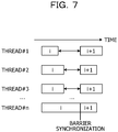
- FIG. 7 is a diagram for explaining barrier synchronization.
- an ith (i is an integer of 1 or more) process is performed in parallel in threads #1 to #n (n is an integer of 2 or more), and the latest process is completed in the thread #n.
- the threads other than the latest thread #n wait until the ith process is completed in the thread #n, and when the ith process is completed in the thread #n, a (i+1)th process is started in the threads #1 to #n.
- the processor includes a storage configured to receive a snapshot of a state of the processor prior to performing a set of calculations in the approximation, and an indicator indicating an amount of error accumulated while the set of calculations is performed in the approximation.
- a state of the processor is restored from the storage to the snapshot.
- an object is to reduce a waiting time of a processing unit in barrier synchronization and improve a processing speed.
- a barrier synchronization circuit that performs barrier synchronization of a plurality of processes executed in parallel by a plurality of processing circuits, the barrier synchronization circuit includes a first determination circuit and an instruction circuit.
- the first determination circuit configured to determine whether or not the number of first processing circuits among the plurality of the processing circuits is equal to or greater than a first threshold value, the first processing circuits having completed the process, and an instruction circuit configured to instruct a second processing circuit among the plurality of the processing circuits to forcibly stop the process when it is determined that the number is equal to or greater than the first threshold value by the first determination circuit, the second processing circuit having not completed the process.
- a barrier synchronization circuit performs barrier synchronization of a plurality of processes executed in parallel by a plurality of processing circuits
- the barrier synchronization circuit includes a first determination circuit and an instruction circuit.
- the first determination circuit determines whether or not an elapsed time from a completion of a process by any one of the processing circuits is equal to or greater than a first threshold value.
- the instruction circuit instructs a processing circuit in which a process is not completed to forcibly stop the process when it is determined by the first determination circuit that the elapsed time is equal to or greater than a first threshold value.
- the present disclosure may increase a processing speed.
- FIG. 1 is a diagram for explaining the AC parallelization according to the example.
- a register indicates processing states of n threads.
- a bit corresponding to a thread that completes a process is 1, and a bit corresponding to a thread that does not complete a process is 0.
- the barrier synchronization circuit forcibly stops (kills) (n-m) threads in which the process is not completed.
- the barrier synchronization circuit forcibly stops the (n-m) threads in which the process is not completed, and does not wait for the completion of the process of the (n-m) threads. Therefore, it is possible to shorten a waiting time and improve a processing speed.
- an optimization problem such as an LSI arrangement and wiring problem, a lithography pattern creation problem, and a delivery plan problem in which a certain degree of error is allowed, it is possible to improve the processing speed by the AC parallelization according to the example.
- a genetic algorithm when a process for generating an individual of the ith generation in the ith process is performed in parallel by the n threads, the accuracy is lowered by forcibly stopping the (n-m) threads in each generation, but the processing speed is improved.
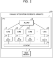
- FIG. 2 is a diagram illustrating a configuration of a parallel information processing apparatus according to an embodiment.
- a parallel information processing apparatus 100 includes a CPU 1 and a main memory 2.
- the CPU 1 is a central processing unit that executes a program.
- the main memory 2 is a random-access memory (RAM) that stores the program executed by the CPU 1 and data used in the program.
- the parallel information processing apparatus 100 may include a plurality of CPUs 1 and main memories 2.
- the CPU 1 includes an AC unit 10, n cores 20, n L1 caches 30, and an L2 cache 40.
- the AC unit 10 is coupled to each core 20.
- Each core 20 is coupled to a corresponding L1 cache 30.
- Each L1 cache 30 is coupled to the L2 cache 40.
- the AC unit 10 is a barrier synchronization circuit that is notified of the completion of the process from the core 20 where the thread, in which the process is completed, operates and performs barrier synchronization.
- the AC unit 10 performs the process based on the mode.
- the AC unit 10 When the mode is 0, the AC unit 10 does not perform the AC parallelization but performs normal barrier synchronization. For example, the AC unit 10 waits for the completion of the process to be notified from all the cores 20.
- the AC unit 10 determines whether or not the number of threads, in which the process is completed, is equal to or greater than a threshold value m. Then, when the number of threads, in which the process is completed, is equal to or greater than the threshold value m, the AC unit 10 determines that a synchronization condition is satisfied and transmits a forced stop signal to the core 20 where the process is not completed.
- the AC unit 10 when the AC unit 10 is notified of the completion of the process from the core 20 where the thread, in which the process is completed for the first time, operates, the AC unit 10 starts counting the number of clocks. Then, the AC unit 10 determines whether or not the number of clocks is equal to or greater than a threshold value c (c is a positive integer). When the number of clocks is equal to or greater than the threshold value c, the AC unit 10 determines that the synchronization condition is satisfied, and transmits the forced stop signal to the core 20 where the process is not completed.
- a threshold value c a positive integer
- the AC unit 10 collects data on the AC parallelization.
- the AC unit 10 collects a time s at which any one of the cores 20 completes the process for the first time, a time m t at which m or more cores 20 complete the process, and a time e at which all the cores 20 complete the process.
- the collected time s, time m t , and time e are taken out from a program, for example.
- the core 20 is a processing apparatus that performs the process.
- the core 20 executes a thread.
- the core 20 notifies the AC unit 10 of the completion of the process of the thread.
- the core 20 receives the forced stop signal from the AC unit 10, the core 20 forcibly stops the thread.
- the core 20 may receive an estimated value of a processing result of the thread together with the forced stop signal. In this case, the thread may perform a next process using the estimated value.
- the L1 cache 30 is a cache that stores some of the instructions and data stored in the main memory 2.
- the core 20 reads an instruction and data from the L1 cache 30 and executes the instruction. When there is no instruction or data to be accessed by the core 20, the L1 cache 30 acquires an instruction or data from the L2 cache 40.
- the L2 cache 40 is a cache that stores some of the instructions and data stored in the main memory 2.
- the L2 cache 40 has a larger capacity and a slower access speed than those of the L1 cache 30.
- the L2 cache 40 acquires the instruction or data from the main memory 2.
- FIG. 3 is a diagram illustrating a configuration of the AC unit 10.
- the AC unit 10 includes an ADD circuit 11, an m register circuit 12, a comparison circuit 13, an OR circuit 14, a c register circuit 15, a counter circuit 16, an OR circuit 17, a P register circuit 18, and an output circuit 19.
- the AC unit 10 includes a setting circuit 51, a setting circuit 52, a timer circuit 61, a time acquisition circuit 62, an SME register circuit 63, a reading circuit 64, a k register circuit 71, a reading circuit 72, a mode determination circuit 81, and an initialization circuit 91.
- the ADD circuit 11 inputs a completion signal to be set to 1 when each core 20 completes the process of the thread, and outputs the number of 1 of the completion signal. When the process of the thread is not completed, each core 20 sets the completion signal to 0.
- the m register circuit 12 stores a threshold value m.
- the threshold value m is designated by a program. However, the threshold value m may be determined by the setting circuit 51 as described later.
- the comparison circuit 13 compares the number output from the ADD circuit 11 with the threshold value m stored in the m register circuit 12, and outputs 1 to the OR circuit 17 when the number output from the ADD circuit 11 becomes equal to or greater than the threshold value m.
- the mode signal indicates 0 or 2
- n is set in the m register circuit 12.
- the mode signal is a signal for designating a mode.
- the value indicated by the mode signal is determined by the mode determination circuit 81.
- the comparison circuit 13 outputs 1 to the time acquisition circuit 62 when the number output from the ADD circuit 11 is 1, m, or n.
- the OR circuit 14 inputs the completion signals and outputs a logical sum of the completion signals.
- the c register circuit 15 stores a threshold value c.
- the threshold value c is designated by a program. However, the threshold value c may be determined by the setting circuit 52 as described later.
- the counter circuit 16 starts counting of the clock when the output of the OR circuit 14 is 1. Then, the counter circuit 16 compares the counted value with the threshold value c stored in the c register circuit 15, and outputs 1 to the OR circuit 17 when the counted value is the threshold value c.
- the OR circuit 17 outputs a logical sum of the output of the comparison circuit 13 and the output of the counter circuit 16.
- the P register circuit 18 stores the completion signal output from the core 20 for each core 20.
- the output circuit 19 transmits the forced stop signal to the core 20 where the process is not completed based on the P register circuit 18.
- the output circuit 19 may transmit an estimated value of a process result together with the forced stop signal.
- the AC unit 10 stores past execution results and an average value of the execution results, and the output circuit 19 transmits the average value of the past execution results as the estimated value.
- the output circuit 19 accumulates the number of the thread instructed to be forcibly stopped in the k register circuit 71 in association with the number of times of barrier synchronization. For example, the output circuit 19 specifies the thread number from the P register circuit 18 by storing the thread number notified from each core 20 in association with the core 20.
- the setting circuit 51 inputs the m signal and sets the threshold value m in the m register circuit 12.
- the m signal is a signal indicating the threshold value m.
- the mode signal indicates 0 or 2
- the setting circuit 51 sets the number n of cores 20 in the m register circuit 12 based on an instruction from the mode determination circuit 81.
- the setting circuit 52 inputs the c signal and sets the threshold value c in the c register circuit 15.
- the c signal is a signal indicating the threshold value c.
- the timer circuit 61 counts a time under barrier synchronization. Upon receiving 1 from the comparison circuit 13, the time acquisition circuit 62 acquires the time from the timer circuit 61 and stores the time in the SME register circuit 63.
- the SME register circuit 63 stores the time s, the time m t , and the time e.
- the reading circuit 64 outputs the time s, the time m t , and the time e from the SME register circuit 63.
- the k register circuit 71 stores the number of the thread to which the output circuit 19 instructs the forced stop as the forced stop thread number in association with the number of times of the barrier synchronization.
- the reading circuit 72 reads the forced stop thread number for each number of times from the k register circuit 71 and outputs the forced stop thread number.
- the mode determination circuit 81 inputs the mode signal and determines a value indicated by the mode signal. Then, when the value indicated by the mode signal is 1, the mode determination circuit 81 operates the counter circuit 16. Further, when the value indicated by the mode signal is 0 or 2, the mode determination circuit 81 instructs the setting circuit 51 to set n in the m register circuit 12. Further, when the value indicated by the mode signal is 2, the mode determination circuit 81 notifies the comparison circuit 13 that the mode is 2.
- the initialization circuit 91 inputs an initialization signal, initializes the P register circuit 18 by 0, and starts the timer circuit 61.
- the initialization signal is generated when the parallel process of the threads is started.
- FIG. 4A to 4B is a diagram illustrating an example of a program for designating the AC parallelization.
- FIG. 4A illustrates a program for which the AC parallelization is not designated
- FIG. 4B illustrates a program for which the AC parallelization is designated.
- the threshold value m and the threshold value c are designated by the set_AC_parameter (m, c).
- the location and mode of the AC parallelization are designated by start_AC_region (mode) and end_AC_region (mode).
- the time s, the time m t , and the time e are acquired by get_AC_value (&S, &M, &E).
- the m signal and the c signal are generated by the set_AC_parameter (m, c), and the threshold value m and the threshold value c are set in the m register circuit 12 and the c register circuit 15 based on the m signal and the c signal.
- the mode signal and the initialization signal are generated by start_AC_region (mode), the P register circuit 18 is initialized based on the initialization signal, and the timer circuit 61 is started.
- FIG. 5 is a flowchart illustrating a flow of process in which the setting circuit 51 determines the threshold value m
- FIG. 6 is a flowchart illustrating a flow of process in which the setting circuit 52 determines the threshold value c.
- the setting circuit 51 sets n to m, instructs the core 20 to execute the thread (step S1), and acquires an accuracy A (step S2). Then, the setting circuit 51 receives an accuracy a c and an error t (step S3).
- a c is an expected accuracy and a c ⁇ A.
- t is an error with a c and is an error capable of securing an expected accuracy. Then, the setting circuit 51 sets n/2 to m, instructs the core 20 to execute the thread (step S4), and acquires the accuracy a (step S5).
- the setting circuit 51 determines whether or not an absolute value of a difference between a c and a is smaller than t (step S6). If the absolute value of the difference is smaller than t, the setting circuit 51 sets a value obtained by adding y x to n/2 or a value obtained by subtracting y x from n/2 to m and instructs the core 20 to execute the thread (step S7).
- x is the number of times step S7 is executed.
- the setting circuit 51 sets a value obtained by adding y x to n/2 to m, and when a ⁇ a c , sets a value obtained by subtracting y x from n/2 to m. Then, the setting circuit 51 returns to step S5.
- the setting circuit 51 determines m as a current value (step S8).
- the AC unit 10 may optimize the AC parallelization function.
- the process illustrated in FIG. 5 may be performed by an apparatus external to the AC unit 10, and the AC unit 10 may receive the threshold value m determined by the external apparatus.
- the setting circuit 52 measures the number of clocks c 0 at the time of completion of the first thread and the number of clocks c all at the time of completion of all threads (step S11), and acquires the accuracy A in the case of completion of all threads (step S12). Then, the setting circuit 52 receives the accuracy a c and the error t (step S13). Then, the setting circuit 52 sets (c all -c 0 )/2 to c, instructs the core 20 to execute the thread (step S14), and acquires the accuracy a (step S15).
- the setting circuit 52 determines whether or not the absolute value of the difference between a c and a is smaller than t (step S16). Then, when the absolute value of the difference between a c and a is smaller than t, the setting circuit 52 sets a value obtained by adding y x to (c all -c 0 )/2 or a value obtained by subtracting y x from (c all -c 0 )/2 to c, and instructs the core 20 to execute the thread (step S17).
- x is the number of times step S17 is executed.
- y x is (c all -c 0 )/2 x+1 .
- y 1 is (c all -c 0 )/2 2 and y 2 is (C all -c 0 )/2 3 .
- the setting circuit 52 sets a value obtained by adding y x to (c all -c 0 )/2 to c, and when a ⁇ a c , sets a value obtained by subtracting y x from (c all -c 0 )/2 to c. Then, the setting circuit 52 returns to step S15.
- the setting circuit 52 determines c as the current value (step S18).
- the AC unit 10 may optimize the AC parallelization function.
- the process illustrated in FIG. 6 may be performed by an apparatus external to the AC unit 10, and the AC unit 10 may receive the threshold value c determined by the external apparatus.
- the comparison circuit 13 compares the number of the cores 20, in which the process is completed, with the threshold value m, and determines whether or not the number of the cores 20 where the process is completed is equal to or greater than the threshold value m. Then, when the number of the cores 20 where the process is completed is equal to or greater than the threshold value m, the output circuit 19 transmits the forced stop signal to the cores 20 where the process is not completed. Therefore, the AC unit 10 may reduce the waiting time in the barrier synchronization and improve the processing speed.
- the counter circuit 16 determines whether or not the elapsed time since any one of the cores 20 completes the process for the first time is equal to or greater than the threshold value c. Then, when the elapsed time since any one of the cores 20 completes the process for the first time is equal to or greater than the threshold value c, the output circuit 19 transmits the forced stop signal to the core 20 where the process is not completed. Therefore, the AC unit 10 may reduce the waiting time in the barrier synchronization and improve the processing speed.
- the mode determination circuit 81 determines the mode and instructs the setting circuit 51 to operate the counter circuit 16 when the mode is 1 and to set n to the m register circuit 12 when the mode is 0 or 2. Further, when the mode is 2, the mode determination circuit 81 notifies the comparison circuit 13 that the mode is 2. Therefore, the mode determination circuit 81 may control the operation of the AC unit 10 based on the mode.
- the m register circuit 12 stores the threshold value m
- the setting circuit 51 determines the optimum value of the threshold value m and sets the optimum value in the m register circuit 12.
- the comparison circuit 13 compares the threshold value m stored in the m register circuit 12 with the number of cores 20 to which the completion is notified. Therefore, the AC unit 10 may optimize the AC parallelization function.
- the c register circuit 15 stores the threshold value c
- the setting circuit 52 determines the optimum value of the threshold value c and sets the optimum value in the c register circuit 15.
- the counter circuit 16 compares the threshold value c stored in the c register circuit 15 with the elapsed time since the completion notification of the process is received for the first time. Therefore, the AC unit 10 may optimize the AC parallelization function.
- the k register circuit 71 stores the forced stop thread number in association with the number of times of the barrier synchronization, and the reading circuit 72 reads and outputs the forced stop thread number and the number of times from the k register circuit 71. Therefore, the AC unit 10 may provide information useful for analysis of the AC parallelization function.
- the output circuit 19 transmits the estimated value of the processing result of the thread to the thread instructed to be forcibly stopped, and thus the AC unit 10 may provide the AC parallelization function without reducing the number of threads.
- the SME register circuit 63 stores the time s, the time m t , and the time e, and the reading circuit 64 reads and outputs the time s, the time m t , and the time e from the SME register circuit 63. Therefore, the AC unit 10 may provide information useful for analysis of the AC parallelization function.
- the thread is allocated to the core 20 in the embodiment.
- another processing unit such as a process may be allocated to the core 20.
- a thread may be assigned to another processing apparatus such as a processor or a CPU instead of the core 20.
- the parallel information processing apparatus includes a plurality of CPUs, and the AC unit is provided outside the CPUs.
- the mode when the mode is 1, a case where both the comparison circuit 13 and the counter circuit 16 operate is described, but the case where the mode is 1 may be subdivided.
- 3 modes that is, a mode in which only the comparison circuit 13 operates, a mode in which only the counter circuit 16 operates, and a mode in which both the comparison circuit 13 and the counter circuit 16 operate, may be provided.
Landscapes
- Engineering & Computer Science (AREA)
- Theoretical Computer Science (AREA)
- Software Systems (AREA)
- Physics & Mathematics (AREA)
- General Engineering & Computer Science (AREA)
- General Physics & Mathematics (AREA)
- Quality & Reliability (AREA)
- Library & Information Science (AREA)
- Hardware Redundancy (AREA)
- Multi Processors (AREA)
Abstract
Description
- The embodiments discussed herein are related to a barrier synchronization circuit, a barrier synchronization method, and a parallel information processing apparatus.
- In a parallel information processing apparatus in which a plurality of processing units perform a parallel process while synchronizing with each other, there is barrier synchronization as a method of synchronizing with each other. Here, the processing unit is a unit for using the processing apparatus. For example, a core of a central processing unit (CPU) is a processing apparatus, and a thread is a processing unit. The parallel information processing apparatus has a plurality of cores, and each core executes an assigned thread.
-
FIG. 7 is a diagram for explaining barrier synchronization. InFIG. 7 , an ith (i is an integer of 1 or more) process is performed in parallel inthreads # 1 to #n (n is an integer of 2 or more), and the latest process is completed in the thread #n. As illustrated inFIG. 7 , in the barrier synchronization, the threads other than the latest thread #n wait until the ith process is completed in the thread #n, and when the ith process is completed in the thread #n, a (i+1)th process is started in thethreads # 1 to #n. - As a technique of the related art, there is a processor that recovers from an excessive approximation calculation error when approximation calculation is performed. The processor includes a storage configured to receive a snapshot of a state of the processor prior to performing a set of calculations in the approximation, and an indicator indicating an amount of error accumulated while the set of calculations is performed in the approximation. When the processor detects that the amount of accumulated error exceeds an error limit, a state of the processor is restored from the storage to the snapshot.
- [PTL 1] Japanese National Publication of International Patent Application No.
2016-524748 - In the barrier synchronization illustrated in
FIG. 7 , there is a problem that a processing unit (thread) that has the completed process first waits until all remaining processing units complete the process. - According to one aspects of the present disclosure, an object is to reduce a waiting time of a processing unit in barrier synchronization and improve a processing speed.
- In one aspect, A barrier synchronization circuit that performs barrier synchronization of a plurality of processes executed in parallel by a plurality of processing circuits, the barrier synchronization circuit includes a first determination circuit and an instruction circuit. The first determination circuit configured to determine whether or not the number of first processing circuits among the plurality of the processing circuits is equal to or greater than a first threshold value, the first processing circuits having completed the process, and an instruction circuit configured to instruct a second processing circuit among the plurality of the processing circuits to forcibly stop the process when it is determined that the number is equal to or greater than the first threshold value by the first determination circuit, the second processing circuit having not completed the process.
- In another aspect, a barrier synchronization circuit performs barrier synchronization of a plurality of processes executed in parallel by a plurality of processing circuits, the barrier synchronization circuit includes a first determination circuit and an instruction circuit. The first determination circuit determines whether or not an elapsed time from a completion of a process by any one of the processing circuits is equal to or greater than a first threshold value. The instruction circuit instructs a processing circuit in which a process is not completed to forcibly stop the process when it is determined by the first determination circuit that the elapsed time is equal to or greater than a first threshold value.
- In one aspect, the present disclosure may increase a processing speed.
-
-
FIG. 1 is a diagram for explaining AC parallelization according to an example; -
FIG. 2 is a diagram illustrating a configuration of a parallel information processing apparatus according to an example; -
FIG. 3 is a diagram illustrating a configuration of an AC unit; -
FIG. 4A is diagram illustrating an example of a program for designating AC parallelization; -
FIG. 4B is diagram illustrating an example of a program for designating AC parallelization; -
FIG. 5 is a flowchart illustrating a flow of a process in which a setting circuit determines a threshold value m; -
FIG. 6 is a flowchart illustrating a flow of a process in which the setting circuit determines a threshold value c; and -
FIG. 7 is a diagram for explaining barrier synchronization. - Hereinafter, examples of a barrier synchronization circuit, a barrier synchronization method, and a parallel information processing apparatus disclosed in the present application will be described in detail with reference to the drawings. The examples do not limit the disclosed technique.
- First, approximate computing (AC) parallelization according to an example will be described.
FIG. 1 is a diagram for explaining the AC parallelization according to the example. InFIG. 1 , a register indicates processing states of n threads. A bit corresponding to a thread that completes a process is 1, and a bit corresponding to a thread that does not complete a process is 0. - As illustrated in
FIG. 1 , in the AC parallelization according to the example, when the process is completed in m (1 ≤ m < n) of n threads, the barrier synchronization circuit forcibly stops (kills) (n-m) threads in which the process is not completed. - As described above, in the AC parallelization according to the embodiment, the barrier synchronization circuit forcibly stops the (n-m) threads in which the process is not completed, and does not wait for the completion of the process of the (n-m) threads. Therefore, it is possible to shorten a waiting time and improve a processing speed. In an optimization problem such as an LSI arrangement and wiring problem, a lithography pattern creation problem, and a delivery plan problem in which a certain degree of error is allowed, it is possible to improve the processing speed by the AC parallelization according to the example. For example, in a genetic algorithm (GA), when a process for generating an individual of the ith generation in the ith process is performed in parallel by the n threads, the accuracy is lowered by forcibly stopping the (n-m) threads in each generation, but the processing speed is improved.
- Next, a configuration of the parallel information processing apparatus according to the embodiment will be described.
FIG. 2 is a diagram illustrating a configuration of a parallel information processing apparatus according to an embodiment. As illustrated inFIG. 2 , a parallelinformation processing apparatus 100 according to the embodiment includes aCPU 1 and amain memory 2. TheCPU 1 is a central processing unit that executes a program. Themain memory 2 is a random-access memory (RAM) that stores the program executed by theCPU 1 and data used in the program. The parallelinformation processing apparatus 100 may include a plurality ofCPUs 1 andmain memories 2. - The
CPU 1 includes anAC unit 10,n cores 20,n L1 caches 30, and anL2 cache 40. TheAC unit 10 is coupled to eachcore 20. Eachcore 20 is coupled to acorresponding L1 cache 30. EachL1 cache 30 is coupled to theL2 cache 40. - The
AC unit 10 is a barrier synchronization circuit that is notified of the completion of the process from thecore 20 where the thread, in which the process is completed, operates and performs barrier synchronization. TheAC unit 10 performs the process based on the mode. - When the mode is 0, the
AC unit 10 does not perform the AC parallelization but performs normal barrier synchronization. For example, theAC unit 10 waits for the completion of the process to be notified from all thecores 20. - When the mode is 1, if the
AC unit 10 is notified of the completion of the process from thecore 20 where the thread, in which the process is completed, operates, theAC unit 10 determines whether or not the number of threads, in which the process is completed, is equal to or greater than a threshold value m. Then, when the number of threads, in which the process is completed, is equal to or greater than the threshold value m, theAC unit 10 determines that a synchronization condition is satisfied and transmits a forced stop signal to thecore 20 where the process is not completed. - Further, when the
AC unit 10 is notified of the completion of the process from the core 20 where the thread, in which the process is completed for the first time, operates, theAC unit 10 starts counting the number of clocks. Then, theAC unit 10 determines whether or not the number of clocks is equal to or greater than a threshold value c (c is a positive integer). When the number of clocks is equal to or greater than the threshold value c, theAC unit 10 determines that the synchronization condition is satisfied, and transmits the forced stop signal to the core 20 where the process is not completed. - When the mode is 2, the
AC unit 10 collects data on the AC parallelization. TheAC unit 10 collects a time s at which any one of thecores 20 completes the process for the first time, a time mt at which m ormore cores 20 complete the process, and a time e at which all thecores 20 complete the process. The collected time s, time mt, and time e are taken out from a program, for example. - The
core 20 is a processing apparatus that performs the process. Thecore 20 executes a thread. When the process of the thread is completed, thecore 20 notifies theAC unit 10 of the completion of the process of the thread. Further, when thecore 20 receives the forced stop signal from theAC unit 10, the core 20 forcibly stops the thread. However, thecore 20 may receive an estimated value of a processing result of the thread together with the forced stop signal. In this case, the thread may perform a next process using the estimated value. - The
L1 cache 30 is a cache that stores some of the instructions and data stored in themain memory 2. The core 20 reads an instruction and data from theL1 cache 30 and executes the instruction. When there is no instruction or data to be accessed by thecore 20, theL1 cache 30 acquires an instruction or data from theL2 cache 40. - The
L2 cache 40 is a cache that stores some of the instructions and data stored in themain memory 2. TheL2 cache 40 has a larger capacity and a slower access speed than those of theL1 cache 30. When there is no instruction or data to be accessed by theL1 cache 30, theL2 cache 40 acquires the instruction or data from themain memory 2. -
FIG. 3 is a diagram illustrating a configuration of theAC unit 10. As illustrated inFIG. 3 , theAC unit 10 includes an ADD circuit 11, an m register circuit 12, acomparison circuit 13, an OR circuit 14,a c register circuit 15, a counter circuit 16, an OR circuit 17, a P register circuit 18, and anoutput circuit 19. Further, theAC unit 10 includes asetting circuit 51, a settingcircuit 52, a timer circuit 61, atime acquisition circuit 62, anSME register circuit 63, areading circuit 64,a k register circuit 71, a reading circuit 72, amode determination circuit 81, and an initialization circuit 91. - The ADD circuit 11 inputs a completion signal to be set to 1 when each core 20 completes the process of the thread, and outputs the number of 1 of the completion signal. When the process of the thread is not completed, each core 20 sets the completion signal to 0. The m register circuit 12 stores a threshold value m. The threshold value m is designated by a program. However, the threshold value m may be determined by the setting
circuit 51 as described later. - The
comparison circuit 13 compares the number output from the ADD circuit 11 with the threshold value m stored in the m register circuit 12, andoutputs 1 to the OR circuit 17 when the number output from the ADD circuit 11 becomes equal to or greater than the threshold value m. When the mode signal indicates 0 or 2, n is set in the m register circuit 12. Here, the mode signal is a signal for designating a mode. The value indicated by the mode signal is determined by themode determination circuit 81. Further, when the mode signal indicates 2, thecomparison circuit 13outputs 1 to thetime acquisition circuit 62 when the number output from the ADD circuit 11 is 1, m, or n. - The OR circuit 14 inputs the completion signals and outputs a logical sum of the completion signals. The
c register circuit 15 stores a threshold value c. The threshold value c is designated by a program. However, the threshold value c may be determined by the settingcircuit 52 as described later. - When the mode signal indicates 1, the counter circuit 16 starts counting of the clock when the output of the OR circuit 14 is 1. Then, the counter circuit 16 compares the counted value with the threshold value c stored in the
c register circuit 15, andoutputs 1 to the OR circuit 17 when the counted value is the threshold value c. - The OR circuit 17 outputs a logical sum of the output of the
comparison circuit 13 and the output of the counter circuit 16. The P register circuit 18 stores the completion signal output from thecore 20 for each core 20. - When the output of the OR circuit 17 is 1, the
output circuit 19 transmits the forced stop signal to the core 20 where the process is not completed based on the P register circuit 18. Theoutput circuit 19 may transmit an estimated value of a process result together with the forced stop signal. For example, theAC unit 10 stores past execution results and an average value of the execution results, and theoutput circuit 19 transmits the average value of the past execution results as the estimated value. - Further, the
output circuit 19 accumulates the number of the thread instructed to be forcibly stopped in thek register circuit 71 in association with the number of times of barrier synchronization. For example, theoutput circuit 19 specifies the thread number from the P register circuit 18 by storing the thread number notified from each core 20 in association with thecore 20. - The setting
circuit 51 inputs the m signal and sets the threshold value m in the m register circuit 12. Here, the m signal is a signal indicating the threshold value m. When the mode signal indicates 0 or 2, the settingcircuit 51 sets the number n ofcores 20 in the m register circuit 12 based on an instruction from themode determination circuit 81. - The setting
circuit 52 inputs the c signal and sets the threshold value c in thec register circuit 15. Here, the c signal is a signal indicating the threshold value c. - The timer circuit 61 counts a time under barrier synchronization. Upon receiving 1 from the
comparison circuit 13, thetime acquisition circuit 62 acquires the time from the timer circuit 61 and stores the time in theSME register circuit 63. TheSME register circuit 63 stores the time s, the time mt, and the time e. Thereading circuit 64 outputs the time s, the time mt, and the time e from theSME register circuit 63. - The
k register circuit 71 stores the number of the thread to which theoutput circuit 19 instructs the forced stop as the forced stop thread number in association with the number of times of the barrier synchronization. The reading circuit 72 reads the forced stop thread number for each number of times from thek register circuit 71 and outputs the forced stop thread number. - The
mode determination circuit 81 inputs the mode signal and determines a value indicated by the mode signal. Then, when the value indicated by the mode signal is 1, themode determination circuit 81 operates the counter circuit 16. Further, when the value indicated by the mode signal is 0 or 2, themode determination circuit 81 instructs the settingcircuit 51 to set n in the m register circuit 12. Further, when the value indicated by the mode signal is 2, themode determination circuit 81 notifies thecomparison circuit 13 that the mode is 2. - The initialization circuit 91 inputs an initialization signal, initializes the P register circuit 18 by 0, and starts the timer circuit 61. The initialization signal is generated when the parallel process of the threads is started.
-
FIG. 4A to 4B is a diagram illustrating an example of a program for designating the AC parallelization.FIG. 4A illustrates a program for which the AC parallelization is not designated, andFIG. 4B illustrates a program for which the AC parallelization is designated. As illustrated inFIG. 4B , the threshold value m and the threshold value c are designated by the set_AC_parameter (m, c). Further, the location and mode of the AC parallelization are designated by start_AC_region (mode) and end_AC_region (mode). Further, the time s, the time mt, and the time e are acquired by get_AC_value (&S, &M, &E). - Further, the m signal and the c signal are generated by the set_AC_parameter (m, c), and the threshold value m and the threshold value c are set in the m register circuit 12 and the
c register circuit 15 based on the m signal and the c signal. Further, the mode signal and the initialization signal are generated by start_AC_region (mode), the P register circuit 18 is initialized based on the initialization signal, and the timer circuit 61 is started. - Instead of designating the threshold value m and the threshold value c by a program, the setting
circuit 51 and the settingcircuit 52 may determine the threshold value m and the threshold value c, respectively.FIG. 5 is a flowchart illustrating a flow of process in which thesetting circuit 51 determines the threshold value m, andFIG. 6 is a flowchart illustrating a flow of process in which thesetting circuit 52 determines the threshold value c. - As illustrated in
FIG. 5 , the settingcircuit 51 sets n to m, instructs the core 20 to execute the thread (step S1), and acquires an accuracy A (step S2). Then, the settingcircuit 51 receives an accuracy ac and an error t (step S3). Here, ac is an expected accuracy and ac < A. Also, t is an error with ac and is an error capable of securing an expected accuracy. Then, the settingcircuit 51 sets n/2 to m, instructs the core 20 to execute the thread (step S4), and acquires the accuracy a (step S5). - Then, the setting
circuit 51 determines whether or not an absolute value of a difference between ac and a is smaller than t (step S6). If the absolute value of the difference is smaller than t, the settingcircuit 51 sets a value obtained by adding yx to n/2 or a value obtained by subtracting yx from n/2 to m and instructs the core 20 to execute the thread (step S7). Here, x is the number of times step S7 is executed. Further, yx is n/2x+1. For example, y1 is (n-m)/2 = n/22, and y2 is n/23. Further, when a ≥ ac, the settingcircuit 51 sets a value obtained by adding yx to n/2 to m, and when a < ac, sets a value obtained by subtracting yx from n/2 to m. Then, the settingcircuit 51 returns to step S5. - On the other hand, when the absolute value of the difference between ac and a is not smaller than t, the setting
circuit 51 determines m as a current value (step S8). - As described above, since the setting
circuit 51 determines the threshold value m, theAC unit 10 may optimize the AC parallelization function. The process illustrated inFIG. 5 may be performed by an apparatus external to theAC unit 10, and theAC unit 10 may receive the threshold value m determined by the external apparatus. - As illustrated in
FIG. 6 , the settingcircuit 52 measures the number of clocks c0 at the time of completion of the first thread and the number of clocks call at the time of completion of all threads (step S11), and acquires the accuracy A in the case of completion of all threads (step S12). Then, the settingcircuit 52 receives the accuracy ac and the error t (step S13). Then, the settingcircuit 52 sets (call-c0)/2 to c, instructs the core 20 to execute the thread (step S14), and acquires the accuracy a (step S15). - Then, the setting
circuit 52 determines whether or not the absolute value of the difference between ac and a is smaller than t (step S16). Then, when the absolute value of the difference between ac and a is smaller than t, the settingcircuit 52 sets a value obtained by adding yx to (call-c0)/2 or a value obtained by subtracting yx from (call-c0)/2 to c, and instructs the core 20 to execute the thread (step S17). Here, x is the number of times step S17 is executed. Also, yx is (call-c0)/2x+1. For example, y1 is (call-c0)/22 and y2 is (Call-c0)/23. Further, when a ≥ ac, the settingcircuit 52 sets a value obtained by adding yx to (call-c0)/2 to c, and when a < ac, sets a value obtained by subtracting yx from (call-c0)/2 to c. Then, the settingcircuit 52 returns to step S15. - On the other hand, when the absolute value of the difference between ac and a is not smaller than t, the setting
circuit 52 determines c as the current value (step S18). - As described above, since the setting
circuit 51 determines the threshold value c, theAC unit 10 may optimize the AC parallelization function. The process illustrated inFIG. 6 may be performed by an apparatus external to theAC unit 10, and theAC unit 10 may receive the threshold value c determined by the external apparatus. - As described above, in the embodiment, the
comparison circuit 13 compares the number of thecores 20, in which the process is completed, with the threshold value m, and determines whether or not the number of thecores 20 where the process is completed is equal to or greater than the threshold value m. Then, when the number of thecores 20 where the process is completed is equal to or greater than the threshold value m, theoutput circuit 19 transmits the forced stop signal to thecores 20 where the process is not completed. Therefore, theAC unit 10 may reduce the waiting time in the barrier synchronization and improve the processing speed. - Further, in the embodiment, when the mode is 1, the counter circuit 16 determines whether or not the elapsed time since any one of the
cores 20 completes the process for the first time is equal to or greater than the threshold value c. Then, when the elapsed time since any one of thecores 20 completes the process for the first time is equal to or greater than the threshold value c, theoutput circuit 19 transmits the forced stop signal to the core 20 where the process is not completed. Therefore, theAC unit 10 may reduce the waiting time in the barrier synchronization and improve the processing speed. - Further, in the embodiment, the
mode determination circuit 81 determines the mode and instructs the settingcircuit 51 to operate the counter circuit 16 when the mode is 1 and to set n to the m register circuit 12 when the mode is 0 or 2. Further, when the mode is 2, themode determination circuit 81 notifies thecomparison circuit 13 that the mode is 2. Therefore, themode determination circuit 81 may control the operation of theAC unit 10 based on the mode. - Further, in the embodiment, the m register circuit 12 stores the threshold value m, and the setting
circuit 51 determines the optimum value of the threshold value m and sets the optimum value in the m register circuit 12. Further, thecomparison circuit 13 compares the threshold value m stored in the m register circuit 12 with the number ofcores 20 to which the completion is notified. Therefore, theAC unit 10 may optimize the AC parallelization function. - Further, in the embodiment, the
c register circuit 15 stores the threshold value c, and the settingcircuit 52 determines the optimum value of the threshold value c and sets the optimum value in thec register circuit 15. Further, the counter circuit 16 compares the threshold value c stored in thec register circuit 15 with the elapsed time since the completion notification of the process is received for the first time. Therefore, theAC unit 10 may optimize the AC parallelization function. - Further, in the embodiment, the
k register circuit 71 stores the forced stop thread number in association with the number of times of the barrier synchronization, and the reading circuit 72 reads and outputs the forced stop thread number and the number of times from thek register circuit 71. Therefore, theAC unit 10 may provide information useful for analysis of the AC parallelization function. - Further, in the embodiment, the
output circuit 19 transmits the estimated value of the processing result of the thread to the thread instructed to be forcibly stopped, and thus theAC unit 10 may provide the AC parallelization function without reducing the number of threads. - Further, in the embodiment, the
SME register circuit 63 stores the time s, the time mt, and the time e, and thereading circuit 64 reads and outputs the time s, the time mt, and the time e from theSME register circuit 63. Therefore, theAC unit 10 may provide information useful for analysis of the AC parallelization function. - In the embodiment, the case where the thread is allocated to the
core 20 is described. However, instead of the thread, another processing unit such as a process may be allocated to thecore 20. Alternatively, a thread may be assigned to another processing apparatus such as a processor or a CPU instead of thecore 20. When a thread is allocated to a CPU, the parallel information processing apparatus includes a plurality of CPUs, and the AC unit is provided outside the CPUs. - Further, in the embodiment, when the mode is 1, a case where both the
comparison circuit 13 and the counter circuit 16 operate is described, but the case where the mode is 1 may be subdivided. For example, 3 modes, that is, a mode in which only thecomparison circuit 13 operates, a mode in which only the counter circuit 16 operates, and a mode in which both thecomparison circuit 13 and the counter circuit 16 operate, may be provided.
Claims (12)
- A barrier synchronization circuit that performs barrier synchronization of a plurality of processes executed in parallel by a plurality of processing circuits, the barrier synchronization circuit comprising:a first determination circuit configured to determine whether the number of first processing circuits among the plurality of the processing circuits is equal to or greater than a first threshold value, the first processing circuits having completed the process; andan instruction circuit configured to instruct a second processing circuit among the plurality of the processing circuits to forcibly stop the process when it is determined that the number is equal to or greater than the first threshold value by the first determination circuit, the second processing circuit having not completed the process.
- A barrier synchronization circuit that performs barrier synchronization of a plurality of processes executed in parallel by a plurality of processing circuits, the barrier synchronization circuit comprising:a first determination circuit configured to determine whether an elapsed time since any one of the processing circuits completes a process for the first time is equal to or greater than a first threshold value; andan instruction circuit configured to, when it is determined that the elapsed time is equal to or greater than the first threshold value by the first determination circuit, instruct a processing circuit among the plurality of processing circuits to forcibly stop the process, the processing circuit does not complete the process .
- The barrier synchronization circuit according to claim 1, further comprising:a second determination circuit configured to determine whether an elapsed time since any one of the processing circuits completes a process for the first time is equal to or greater than a second threshold value,wherein the instruction circuit instructs a third processing circuit among the plurality of processing circuits to forcibly stop the process when it is determined that the elapsed time is equal to or greater than the second threshold value by the second determination circuit, the third processing circuit having not completed the process in the elapsed time.
- The barrier synchronization circuit according to claim 3, further comprising:
a third determination circuit configured to determine value of mode that designates an operation of the barrier synchronization, and to operate the second determination circuit when the value is a specific value. - The barrier synchronization circuit according to claim 1, 3, or 4, further comprising:a threshold value storage circuit configured to store one or more threshold value including the first threshold value; anda setting circuit configured to determine first threshold value and set the first threshold value in the threshold value storage circuit,wherein the first determination circuit performs determination based on the first threshold.
- The barrier synchronization circuit according to any one of claims 1, 3 to 5, further comprising:an identifier storage circuit configured to store an identifier in units of process in which the process is executed by the second processing circuit, in association with the number of times of barrier synchronization; anda first output circuit configured to output the identifier and the number of times stored in the identifier storage circuit.
- The barrier synchronization circuit according to any one of claims 1, 3 to 6, wherein
the instruction circuit transmits a result expected in a case where the process is completed when the forced stop of the process is instructed, and instructs execution of a next process. - The barrier synchronization circuit according to any one of claims 3 to 7, further comprising:a time storage circuit configured to store a time at which any one of the processing circuits completes a process for the first time, a time at which the processing circuits of the number equal to or greater than the first threshold value complete a process, and a time at which the processing circuit completes a process; anda second output circuit configured to output the time stored in the time storage circuit.
- A barrier synchronization method for performing barrier synchronization of a plurality of processes executed in parallel by a plurality of processing circuits, the barrier synchronization method comprising:determining whether or not the number of first processing circuits among the plurality of the processing circuits which completes a process is equal to or greater than a first threshold value the first processing circuits having completed the process; andinstructing a second processing circuit among the plurality of the processing circuits to forcibly stop the process when it is determined that the number is equal to or greater than the first threshold value, the second processing circuit having not completed the process.
- A barrier synchronization method for performing barrier synchronization of a plurality of processes executed in parallel by a plurality of processing circuits, the barrier synchronization method comprising:determining whether or not an elapsed time since any one of the processing circuits completes a process for the first time is equal to or greater than a first threshold value; andwhen it is determined that the elapsed time is equal to or greater than the first threshold value, instructing a processing circuit among the plurality of processing circuits to forcibly stop the process, the processing circuit does not complete a process.
- A parallel information processing apparatus comprising:a determination circuit configured to determine whether the number of first processing circuits among a plurality of the processing circuits is equal to or greater than a first threshold value, the first processing circuits having completed the process; andan instruction circuit configured to instruct a second processing circuit among the plurality of the processing circuits to forcibly stop the process when it is determined that the number is equal to or greater than the first threshold value by the first determination circuit, the second processing circuit having not completed the process.
- A parallel information processing apparatus comprising:a determination circuit configured to determine whether an elapsed time since any one of the processing circuits completes a process for the first time is equal to or greater than a first threshold value; andan instruction circuit configured to, when it is determined that the elapsed time is equal to or greater than the first threshold value by the first determination circuit, instruct a processing circuit among the plurality of processing circuits to forcibly stop the process, the processing circuit does not complete the process.
Applications Claiming Priority (1)
| Application Number | Priority Date | Filing Date | Title |
|---|---|---|---|
| JP2019165768A JP2021043740A (en) | 2019-09-11 | 2019-09-11 | Barrier synchronization circuit, barrier synchronization method and parallel information processing device |
Publications (1)
| Publication Number | Publication Date |
|---|---|
| EP3792764A1 true EP3792764A1 (en) | 2021-03-17 |
Family
ID=72470152
Family Applications (1)
| Application Number | Title | Priority Date | Filing Date |
|---|---|---|---|
| EP20195270.2A Withdrawn EP3792764A1 (en) | 2019-09-11 | 2020-09-09 | Barrier synchronization circuit, barrier synchronization method, and parallel information processing apparatus |
Country Status (4)
| Country | Link |
|---|---|
| US (1) | US11709718B2 (en) |
| EP (1) | EP3792764A1 (en) |
| JP (1) | JP2021043740A (en) |
| CN (1) | CN112486728A (en) |
Families Citing this family (3)
| Publication number | Priority date | Publication date | Assignee | Title |
|---|---|---|---|---|
| JP7548144B2 (en) * | 2021-07-06 | 2024-09-10 | 株式会社デンソー | Electronic Control Unit |
| JP7771697B2 (en) * | 2021-12-08 | 2025-11-18 | 富士通株式会社 | Processor, information processing device, and information processing method |
| US20240273628A1 (en) * | 2023-02-10 | 2024-08-15 | The Prudential Insurance Company Of America | Financial simulator guided by investor utility |
Citations (4)
| Publication number | Priority date | Publication date | Assignee | Title |
|---|---|---|---|---|
| US20140007111A1 (en) * | 2012-06-28 | 2014-01-02 | Marek Targowski | Systems, methods, and computer program products for preemption of threads at a synchronization barrier |
| JP2016062388A (en) * | 2014-09-19 | 2016-04-25 | 日本電気株式会社 | Information processing apparatus, information processing method, and program thereof |
| JP2016524748A (en) | 2014-02-10 | 2016-08-18 | ヴィア アライアンス セミコンダクター カンパニー リミテッド | A processor that recovers from excessive approximate calculation errors |
| JP2017016250A (en) * | 2015-06-29 | 2017-01-19 | 日本電気株式会社 | Barrier synchronization device, barrier synchronization method, and program |
Family Cites Families (9)
| Publication number | Priority date | Publication date | Assignee | Title |
|---|---|---|---|---|
| JP2014063278A (en) * | 2012-09-20 | 2014-04-10 | Kyushu Univ | Synchronous processing circuit and synchronous processing method |
| US10303477B2 (en) * | 2015-06-26 | 2019-05-28 | Intel Corporation | Persistent commit processors, methods, systems, and instructions |
| US10324730B2 (en) * | 2016-03-24 | 2019-06-18 | Mediatek, Inc. | Memory shuffle engine for efficient work execution in a parallel computing system |
| US10013283B1 (en) * | 2016-08-15 | 2018-07-03 | Datacore Software Corporation | Methods and apparatus for data request scheduling in performing parallel IO operations |
| US10146533B2 (en) * | 2016-09-29 | 2018-12-04 | Intel Corporation | Instruction and logic for detecting numeric accumulation error |
| US10409614B2 (en) * | 2017-04-24 | 2019-09-10 | Intel Corporation | Instructions having support for floating point and integer data types in the same register |
| GB2569274B (en) * | 2017-10-20 | 2020-07-15 | Graphcore Ltd | Synchronization amongst processor tiles |
| US10776225B2 (en) * | 2018-06-29 | 2020-09-15 | Hewlett Packard Enterprise Development Lp | Proactive cluster compute node migration at next checkpoint of cluster cluster upon predicted node failure |
| US11055685B2 (en) * | 2019-06-26 | 2021-07-06 | Capital One Services, Llc | Sorted parallel processing of a large dataset |
-
2019
- 2019-09-11 JP JP2019165768A patent/JP2021043740A/en active Pending
-
2020
- 2020-09-08 US US17/013,896 patent/US11709718B2/en active Active
- 2020-09-08 CN CN202010934575.6A patent/CN112486728A/en active Pending
- 2020-09-09 EP EP20195270.2A patent/EP3792764A1/en not_active Withdrawn
Patent Citations (4)
| Publication number | Priority date | Publication date | Assignee | Title |
|---|---|---|---|---|
| US20140007111A1 (en) * | 2012-06-28 | 2014-01-02 | Marek Targowski | Systems, methods, and computer program products for preemption of threads at a synchronization barrier |
| JP2016524748A (en) | 2014-02-10 | 2016-08-18 | ヴィア アライアンス セミコンダクター カンパニー リミテッド | A processor that recovers from excessive approximate calculation errors |
| JP2016062388A (en) * | 2014-09-19 | 2016-04-25 | 日本電気株式会社 | Information processing apparatus, information processing method, and program thereof |
| JP2017016250A (en) * | 2015-06-29 | 2017-01-19 | 日本電気株式会社 | Barrier synchronization device, barrier synchronization method, and program |
Also Published As
| Publication number | Publication date |
|---|---|
| US20210073048A1 (en) | 2021-03-11 |
| JP2021043740A (en) | 2021-03-18 |
| CN112486728A (en) | 2021-03-12 |
| US11709718B2 (en) | 2023-07-25 |
Similar Documents
| Publication | Publication Date | Title |
|---|---|---|
| EP3792764A1 (en) | Barrier synchronization circuit, barrier synchronization method, and parallel information processing apparatus | |
| US9632822B2 (en) | Multi-core device and multi-thread scheduling method thereof | |
| EP2306313A1 (en) | Method and apparatus for high speed cross-thread interrupts in a multithreaded processor | |
| KR100617357B1 (en) | Zero overhead computer interrupts caused by task switching | |
| EP3091434A1 (en) | Chip starting method, multi-core processor chip and storage medium | |
| EP2580657B1 (en) | Information processing device and method | |
| EP3451122A1 (en) | Power management in an integrated circuit | |
| JP2002215599A (en) | Multiprocessor system and control method thereof | |
| CN109614153B (en) | Multi-core chip and system | |
| WO2020009989A1 (en) | Systems and methods for implementing an intelligence processing computing architecture | |
| US9588811B2 (en) | Method and apparatus for analysis of thread latency | |
| JP2007241918A (en) | Processor device | |
| US11693592B2 (en) | Memory system | |
| US9513969B2 (en) | Method for the management of task execution in a computer system | |
| US20110161982A1 (en) | Task Controlling A Multitask System | |
| CN113220495B (en) | Method and device for processing process abnormal event, electronic equipment and storage medium | |
| CN113886196A (en) | On-chip power consumption management method, electronic device and storage medium | |
| EP3312726A1 (en) | Cpu monitoring device | |
| US20160103704A1 (en) | Data processing device and method of controlling the same | |
| CN118132316A (en) | Jitter detection method, device and equipment for key task processes in operating system | |
| US10387190B2 (en) | System and method of executing a plurality of threads using thread switching on execution time-out using instruction re-write | |
| CN119576410B (en) | A processor and instruction execution method | |
| CN114556120A (en) | Method, arrangement and computer program product for organizing the excitation of a processing path for testing microcircuits | |
| US20230385100A1 (en) | Computer system using energy barrier instructions | |
| US20130060508A1 (en) | Test condition setting method, current variation testing method, and information processing apparatus |
Legal Events
| Date | Code | Title | Description |
|---|---|---|---|
| PUAI | Public reference made under article 153(3) epc to a published international application that has entered the european phase |
Free format text: ORIGINAL CODE: 0009012 |
|
| STAA | Information on the status of an ep patent application or granted ep patent |
Free format text: STATUS: THE APPLICATION HAS BEEN PUBLISHED |
|
| AK | Designated contracting states |
Kind code of ref document: A1 Designated state(s): AL AT BE BG CH CY CZ DE DK EE ES FI FR GB GR HR HU IE IS IT LI LT LU LV MC MK MT NL NO PL PT RO RS SE SI SK SM TR |
|
| AX | Request for extension of the european patent |
Extension state: BA ME |
|
| STAA | Information on the status of an ep patent application or granted ep patent |
Free format text: STATUS: REQUEST FOR EXAMINATION WAS MADE |
|
| 17P | Request for examination filed |
Effective date: 20210722 |
|
| RBV | Designated contracting states (corrected) |
Designated state(s): AL AT BE BG CH CY CZ DE DK EE ES FI FR GB GR HR HU IE IS IT LI LT LU LV MC MK MT NL NO PL PT RO RS SE SI SK SM TR |
|
| STAA | Information on the status of an ep patent application or granted ep patent |
Free format text: STATUS: THE APPLICATION HAS BEEN WITHDRAWN |
|
| 18W | Application withdrawn |
Effective date: 20231023 |