EP3792505A1 - Gewindeeinheit für eine sanitäre montagestruktur - Google Patents
Gewindeeinheit für eine sanitäre montagestruktur Download PDFInfo
- Publication number
- EP3792505A1 EP3792505A1 EP19197260.3A EP19197260A EP3792505A1 EP 3792505 A1 EP3792505 A1 EP 3792505A1 EP 19197260 A EP19197260 A EP 19197260A EP 3792505 A1 EP3792505 A1 EP 3792505A1
- Authority
- EP
- European Patent Office
- Prior art keywords
- clamping
- section
- bearing
- thread unit
- screw
- Prior art date
- Legal status (The legal status is an assumption and is not a legal conclusion. Google has not performed a legal analysis and makes no representation as to the accuracy of the status listed.)
- Granted
Links
Images




Classifications
-
- E—FIXED CONSTRUCTIONS
- E03—WATER SUPPLY; SEWERAGE
- E03D—WATER-CLOSETS OR URINALS WITH FLUSHING DEVICES; FLUSHING VALVES THEREFOR
- E03D11/00—Other component parts of water-closets, e.g. noise-reducing means in the flushing system, flushing pipes mounted in the bowl, seals for the bowl outlet, devices preventing overflow of the bowl contents; devices forming a water seal in the bowl after flushing, devices eliminating obstructions in the bowl outlet or preventing backflow of water and excrements from the waterpipe
- E03D11/13—Parts or details of bowls; Special adaptations of pipe joints or couplings for use with bowls, e.g. provisions in bowl construction preventing backflow of waste-water from the bowl in the flushing pipe or cistern, provisions for a secondary flushing, for noise-reducing
- E03D11/14—Means for connecting the bowl to the wall, e.g. to a wall outlet
- E03D11/143—Mounting frames for toilets and urinals
-
- F—MECHANICAL ENGINEERING; LIGHTING; HEATING; WEAPONS; BLASTING
- F16—ENGINEERING ELEMENTS AND UNITS; GENERAL MEASURES FOR PRODUCING AND MAINTAINING EFFECTIVE FUNCTIONING OF MACHINES OR INSTALLATIONS; THERMAL INSULATION IN GENERAL
- F16B—DEVICES FOR FASTENING OR SECURING CONSTRUCTIONAL ELEMENTS OR MACHINE PARTS TOGETHER, e.g. NAILS, BOLTS, CIRCLIPS, CLAMPS, CLIPS OR WEDGES; JOINTS OR JOINTING
- F16B5/00—Joining sheets or plates, e.g. panels, to one another or to strips or bars parallel to them
- F16B5/02—Joining sheets or plates, e.g. panels, to one another or to strips or bars parallel to them by means of fastening members using screw-thread
- F16B5/0258—Joining sheets or plates, e.g. panels, to one another or to strips or bars parallel to them by means of fastening members using screw-thread using resiliently deformable sleeves, grommets or inserts
-
- E—FIXED CONSTRUCTIONS
- E03—WATER SUPPLY; SEWERAGE
- E03C—DOMESTIC PLUMBING INSTALLATIONS FOR FRESH WATER OR WASTE WATER; SINKS
- E03C1/00—Domestic plumbing installations for fresh water or waste water; Sinks
- E03C1/12—Plumbing installations for waste water; Basins or fountains connected thereto; Sinks
- E03C1/32—Holders or supports for basins
-
- F—MECHANICAL ENGINEERING; LIGHTING; HEATING; WEAPONS; BLASTING
- F16—ENGINEERING ELEMENTS AND UNITS; GENERAL MEASURES FOR PRODUCING AND MAINTAINING EFFECTIVE FUNCTIONING OF MACHINES OR INSTALLATIONS; THERMAL INSULATION IN GENERAL
- F16B—DEVICES FOR FASTENING OR SECURING CONSTRUCTIONAL ELEMENTS OR MACHINE PARTS TOGETHER, e.g. NAILS, BOLTS, CIRCLIPS, CLAMPS, CLIPS OR WEDGES; JOINTS OR JOINTING
- F16B13/00—Dowels or other devices fastened in walls or the like by inserting them in holes made therein for that purpose
- F16B13/04—Dowels or other devices fastened in walls or the like by inserting them in holes made therein for that purpose with parts gripping in the hole or behind the reverse side of the wall after inserting from the front
- F16B13/08—Dowels or other devices fastened in walls or the like by inserting them in holes made therein for that purpose with parts gripping in the hole or behind the reverse side of the wall after inserting from the front with separate or non-separate gripping parts moved into their final position in relation to the body of the device without further manual operation
- F16B13/0816—Dowels or other devices fastened in walls or the like by inserting them in holes made therein for that purpose with parts gripping in the hole or behind the reverse side of the wall after inserting from the front with separate or non-separate gripping parts moved into their final position in relation to the body of the device without further manual operation with a wedging drive-pin
-
- F—MECHANICAL ENGINEERING; LIGHTING; HEATING; WEAPONS; BLASTING
- F16—ENGINEERING ELEMENTS AND UNITS; GENERAL MEASURES FOR PRODUCING AND MAINTAINING EFFECTIVE FUNCTIONING OF MACHINES OR INSTALLATIONS; THERMAL INSULATION IN GENERAL
- F16B—DEVICES FOR FASTENING OR SECURING CONSTRUCTIONAL ELEMENTS OR MACHINE PARTS TOGETHER, e.g. NAILS, BOLTS, CIRCLIPS, CLAMPS, CLIPS OR WEDGES; JOINTS OR JOINTING
- F16B35/00—Screw-bolts; Stay-bolts; Screw-threaded studs; Screws; Set screws
- F16B35/04—Screw-bolts; Stay-bolts; Screw-threaded studs; Screws; Set screws with specially-shaped head or shaft in order to fix the bolt on or in an object
-
- E—FIXED CONSTRUCTIONS
- E03—WATER SUPPLY; SEWERAGE
- E03D—WATER-CLOSETS OR URINALS WITH FLUSHING DEVICES; FLUSHING VALVES THEREFOR
- E03D11/00—Other component parts of water-closets, e.g. noise-reducing means in the flushing system, flushing pipes mounted in the bowl, seals for the bowl outlet, devices preventing overflow of the bowl contents; devices forming a water seal in the bowl after flushing, devices eliminating obstructions in the bowl outlet or preventing backflow of water and excrements from the waterpipe
- E03D11/13—Parts or details of bowls; Special adaptations of pipe joints or couplings for use with bowls, e.g. provisions in bowl construction preventing backflow of waste-water from the bowl in the flushing pipe or cistern, provisions for a secondary flushing, for noise-reducing
- E03D11/14—Means for connecting the bowl to the wall, e.g. to a wall outlet
Definitions
- the present invention relates to a thread unit for a sanitary mounting structure according to claim 1, a sanitary mounting structure according to claim 15 and a method for assembling the sanitary mounting structure according to claim 18.
- the wall bracket comprises an anchor element for fastening to a wall, a threaded rod and a threaded element which can be connected to a mounting frame.
- the EP 3 404 152 also discloses a wall bracket for a sanitary article, in which case the threaded element is fixed to the mounting frame by a plug-in part.
- the invention is based on an object of specifying a thread unit for a sanitary mounting structure which overcomes the disadvantages of the prior art.
- a particularly preferred object is to provide a thread unit which is more simply designed; especially which is manageable.
- a thread unit for a sanitary mounting structure a screw extending along a central axis with a threaded section, a bearing section and an actuating section, a bearing element with a bearing opening in which the screw with the bearing section is rotatably mounted about the central axis and is mounted displaceably from a first position to a second position, and at least one clamping element, which is essentially fixedly mounted on the bearing element, with at least one clamping section for clamping the bearing element to a mounting structure.
- the at least one clamping section is by moving the screw from the first position to the second position radially to the center axis outwards from a mounting position in which the thread unit can be moved relative to the mounting structure to a clamping position in which the thread unit can be firmly clamped to the mounting structure , movable.
- a simple clamping structure can be provided between the thread unit and the sanitary mounting structure.
- a simple clamping structure can be provided without additional elements having to be arranged.
- Clamping the thread unit to the assembly structure also has the advantage that further assembly steps can be carried out easily by one person without the assistance of other installers.
- firmly clamped or firmly clamped is understood to mean that the thread unit as such is connected to the mounting structure in a mechanically fixed manner and preferably free of play with the mounting structure. It is a mechanical clamping. After the connection has been made, the screw can be turned with respect to the bearing element.
- the screw typically acts on an anchor element with an internal thread into which the screw engages, the anchor element being firmly connectable to the building.
- the anchor element can be designed in various ways. For example, as a plate or as a dowel. Via the connection from the anchor plate via the thread unit to the Mounting structure, the mounting structure can be aligned and fastened to the building in its position.
- the clamping element and the screw are preferably made of a metallic material, while the bearing element is preferably made of plastic.
- the operating section includes a structure with which the screw can be operated by means of a tool.
- a hexagon socket, a slot or a cross slot may be mentioned here as an example. Other structures are also conceivable.
- the actuating section is accessible from outside the bearing element.
- At least opposing clamping sections are provided.
- the bearing section preferably has a conical surface area which acts on the at least one clamping section in such a way that the at least one clamping section can be moved from the mounting position to the clamping position when the screw is moved from the first position to the second position.
- the conical surface area is preferably designed to run around the central axis.
- the relative displacement during the movement of the screw from the first position to the second position results in a relative displacement between the conical surface area and the clamping sections, the conical surface area pressing the clamping sections radially outwards as seen from the central axis.
- the diameter of the conical surface area acting on the at least one clamping element increases with increasing advancement of the screw and then reaches the maximum diameter when the screw is in the second position.
- the conical surface area is preferably adjoined by a cylindrical surface area with a constant diameter, the at least one clamping section coming to rest at least partially on the cylindrical surface area in the second position.
- the bearing section of the screw preferably has a cylindrical bearing area with which the screw is mounted in the bearing opening.
- the cylindrical bearing area preferably has a constant diameter.
- the bearing section of the screw preferably further has a recess running around the central axis, at least one latching element, which is fixed relative to its position with respect to the bearing element, engages in the recess when the screw is in the second position.
- the screw to the bearing element is secured with respect to displaceability along the central axis.
- the locking element can be part of the bearing element or part of the clamping element.
- the engagement of the locking element is such that the screw is fixed with respect to a movement along the central axis.
- the screw can still be pivoted about the central axis through the circumferential recess. This means that the screw can be turned when the at least one clamping section
- latching element is fixed to the bearing element is to be understood as meaning that the latching element is either part of the bearing element or that the latching element is provided by a further element which is connected to the bearing element.
- the latching element can particularly preferably be part of the clamping element.
- the at least one clamping section preferably has a free end.
- a locking lug is arranged at the free end.
- the bearing element and / or the clamping element have a stop surface, an intermediate space being formed between the latching lug and the stop surface, in which a wall of the mounting structure can be received.
- the at least one clamping element is fixedly mounted on the bearing element.
- the free end and the locking lug extend out of the bearing opening and preferably protrude from the bearing opening.
- the clamping section is preferably designed to be elastically resilient, with the clamping section being moved from the clamping position into the assembly position when the screw is moved from the second position into the first position. This ensures that the thread unit can be dismantled.
- the clamping element preferably has a sleeve section running around the central axis, from which the at least one clamping section extends at the end, the clamping element with the sleeve section being in contact with the bearing element or being mounted on the bearing element.
- the clamping element is mounted with the sleeve section in the bearing opening.
- the clamping element preferably has a latching section which protrudes radially outward from the sleeve section and engages in a latching receptacle arranged on the bearing element, such that the clamping element is firmly supported on the bearing element with respect to a movement along the central axis.
- the locking element securing the screw with respect to the movement along the central axis is preferably part of the clamping element and extends radially inward from the sleeve section.
- the locking element is part of the clamping element.
- the locking element can also be part of the bearing element.
- the sleeve section at least partially surrounds the bearing element on the outside.
- This encompassing has the advantage that an external bearing can be provided, which can be viewed by the installer.
- the locking element securing the screw with respect to the movement along the central axis is preferably part of the bearing element and extends radially inward from the bearing opening.
- the at least one clamping element is pivotably mounted with its clamping sections on the bearing element.
- the bearing element preferably has a bearing surface on the outside with which the bearing element is mounted in a through opening of an assembly structure.
- a mounting structure comprises at least one thread unit according to the above description and at least one mounting profile with a through opening, the at least one clamping section providing a clamping effect in the area of the through opening.
- the at least one clamping section is preferably positioned in the assembly position in such a way that it can be guided through the through opening.
- the maximum extent of the clamping sections radially to the central axis is accordingly smaller than the inner diameter of the through opening. After the screw has been moved into the second position, the maximum expansion of the clamping sections also increases.
- the mounting profile is preferably a hollow profile with profile walls, the through-opening extending through two opposing profile walls, the threaded unit being guided through both through-openings with the threaded section of the screw first, and the clamping section providing a clamping effect in the area of one of the two through-openings.
- the mounting profile can, however, be an open profile or a sheet metal, in particular a sheet metal strip.
- a method for assembling a mounting structure is characterized by that in a first step the thread unit with the bearing element is positioned in the through opening, that in a second step the screw is moved from the first position to the second position, the movement of the screw moving the at least one clamping section of the at least one clamping element from the mounting position into the clamping position.
- a threaded unit 1 for a sanitary mounting structure 10 is shown.
- the thread unit 1 essentially serves to secure a mounting structure 10, such as a mounting frame, to a wall.
- the thread unit 1 is connected to the mounting structure 10 and then connected to a fastening element that is already mounted on a wall.
- a fastening element can be a dowel or a wall anchor, which are not shown in the figures.
- the mounting structure is essentially used to store a sanitary article, such as a toilet or a washstand.
- the thread unit 1 comprises a screw 2 with a central axis M, a threaded section 3, a bearing section 4 and an actuating section 5. Furthermore, the threaded unit 1 comprises a bearing element 6 with a bearing opening 7, in which the screw 2 with the bearing section 4 around the central axis M is rotatably mounted and displaceable along the central axis M from a first position A to a second position B.
- the thread unit 1 further comprises at least one position element 6 and a clamping element 8, which is fixedly mounted on the bearing element, and has at least one clamping section 9 for clamping the bearing element 6 to a mounting structure 10.
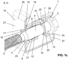
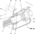
- the screw 2 is in its first position A. Starting from this first position A, the screw 2 can be moved into a second position B. The second position B is in the Figures 1c , 2c , 3c , 4b and 5c shown.
- the screw 2 is moved along the central axis M. This involves a translational movement in the direction or along the central axis M.
- the at least one clamping section 9 is moved radially outward to the central axis M from the first position A to the second position B by the displacement of the screw 2.
- the clamping portion 9 moves from a mounting position C, which is in the Figures 1b , 2 B , 3b , 4a and 5a is shown in a clamping position B, which in the Figures 1c , 2c , 3c , 4b and 5c is shown.
- the thread unit 1 In the assembly position C, the thread unit 1 can be inserted into a through opening 25 on the assembly structure 10.
- the at least one clamping section 9 is pressed radially outwards in relation to the central axis and is clamped to the mounting structure 10 in the area of the through opening 25.
- At least two clamping sections 9 are preferably present.
- the clamping sections 9 are preferably arranged distributed around the central axis at equal intervals.
- the bearing section 4 has a conical surface area 11.
- the conical surface area 11 acts on the at least one clamping section 8 in such a way that the at least one clamping section 8 can be moved from the mounting position C to the clamping position D when the screw 2 is moved from the first position A to the second position B.
- a conical surface area 11 rests on the inside against the at least one clamping section 8.
- the conical surface area 11 is adjoined by a cylindrical surface area 12 with a constant diameter.
- the at least one clamping section 9 lies at least partially on the cylindrical surface area 12. That is to say, the at least one clamping section 9 comes to lie on a determined diameter.
- the bearing section 4 of the screw 2 has a cylindrical bearing area 13 with which the screw 2 is mounted in the bearing opening 7.
- the cylindrical bearing area 13 adjoins the actuating section 5 in each case.
- the bearing section 4 also has a recess 14 running around the central axis M on.
- the recess 14 works together with a latching element 15.
- the latching element 15 engages in the recess 14 when the screw 2 is in the second position B.
- the latching element 15 is firmly positioned in relation to the bearing element 6.
- the locking element 15 different variants are conceivable. According to the first variant, which is in the Figures 1a to 1c is shown, the locking element 15 is part of the clamping element 8, which in turn is fixedly mounted to the bearing element 6.
- the latching element 15 engages radially from the outside into the circumferential recess 14 of the screw 2. This intervention is in the Figure 1c shown in more detail.
- the locking element 15 is an integral part of the bearing element 6 and protrudes radially from the outside into the bearing opening 7.
- the engagement in the circumferential recess 14 is in the Figure 2c and 3c shown.
- the at least one clamping section 9 has a free end 16.
- a locking lug 17 is arranged at the free end 16.
- the bearing element 6 and / or the clamping element 8 each have a stop surface 18.
- the stop surface 18 is part of the bearing element 6.
- the stop surface 18 forms the front face of the bearing element 6.
- the at least one clamping section 9 protrudes with its free end 16 and the locking lug 17 from the bearing opening 7 beyond the front face 18.
- the stop surface 18 is formed by the clamping element 8 itself.
- the at least one clamping section 9 has a corresponding stop surface 18.
- the at least one clamping section 9 is designed to be elastically resilient.
- the clamping section 9 is moved back from the clamping position B to the assembly position C.
- This elastic, deformable suspension is advantageous when it comes to dismantling the thread unit 1 from the assembly structure 10.
- the clamping element 8 has a sleeve section 21 extending around the central axis M. From the sleeve section 21 the at least one clamping section 9 extends away at each end. The clamping element 8 is in contact with the sleeve section 21 with the bearing element 6 or is mounted on the bearing element 6.
- the clamping element 9 is mounted with the sleeve section 21 in the bearing opening 7. Furthermore, the clamping element 8 has a latching section 22 which protrudes radially outward from the sleeve section 21 and engages in a latching receptacle 23 arranged on the bearing element 6. The engagement is such that the clamping element 8 is fixedly mounted on the bearing element 6 with respect to a movement along the central axis M. The clamping element 8 is secured to the bearing element 6 via this engagement.
- the locking element 15 which secures the screw 2 with respect to the movement along the central axis M is also arranged on the sleeve section 20. The latching element 15 protrudes radially from the sleeve section 20 to the central axis M.
- the screw 2 also extends through the sleeve section 21.
- the sleeve section 21 has a diameter which at least partially surrounds the bearing element 6 on the outside. As a result of this encompassing, the sleeve section 21 is firmly supported on the bearing element 6.
- the bearing element 6 has corresponding structures on the outside, on which the sleeve section 21 is mounted.
- the at least one clamping section 9 projects axially from the sleeve section 21 in the direction of the central axis M. These clamping sections 9 are then elastically deformable accordingly.
- the at least one clamping element 8 with its clamping sections 9 is pivotably mounted on the bearing element.
- the clamping elements are on the outside of the bearing element 6.
- the clamping elements 8 are arranged to be pivotable about an axis.
- the bearing element 6 has a bearing surface 24 on the outside. With the bearing surface 24, the bearing element 6 can be stored in a through opening 25 of the mounting structure 10.
- a sanitary mounting structure 10 comprises a thread unit 1 according to the above Description.
- the sanitary mounting structure 10 further comprises at least one mounting profile 26 with a through opening 25.
- the mounting profile 26 has two spaced apart profile walls 27 through which the through opening 25 extends.
- the at least one clamping section engages on a through opening and the bearing element 7 with the bearing surface 24 rests on the other through opening.
- the threaded unit 1 is passed through the two through openings 25 with the threaded section 3 of the screw 2 first, and the clamping section 9 provides a clamping effect in the area of one of the two through openings 25.
Landscapes
- Engineering & Computer Science (AREA)
- General Engineering & Computer Science (AREA)
- Mechanical Engineering (AREA)
- Health & Medical Sciences (AREA)
- Life Sciences & Earth Sciences (AREA)
- Hydrology & Water Resources (AREA)
- Public Health (AREA)
- Water Supply & Treatment (AREA)
- Environmental & Geological Engineering (AREA)
- Connection Of Plates (AREA)
- Toilet Supplies (AREA)
Abstract
Description
- Die vorliegende Erfindung betrifft eine Gewindeeinheit für eine sanitäre Montagestruktur nach Anspruch 1, eine sanitäre Montagestruktur nach Anspruch 15 und Verfahren zur Montage der sanitären Montagestruktur nach Anspruch 18.
- Aus der
EP 3 428 353 ist eine Wandhalterung für einen Sanitärartikel bekannt geworden. Die Wandhalterung umfasst ein Ankerelement zur Befestigung an eine Wand, eine Gewindestange und ein Gewindeelement, welches mit einem Montagerahmen verbindbar ist. - Die
EP 3 404 152 offenbart ebenfalls eine Wandhalterung für einen Sanitärartikel, wobei hier das Gewindeelement durch ein Steckteil zum Montagerahmen fixiert wird. - Die Montage der aus dem Stand der Technik bekannt gewordenen Wandhalterungen an einen Montagerahmen ist vielfach kompliziert. Bei der technischen Lehre der
EP 3 404 152 muss ein entsprechendes Steckteil eingesetzt werden, was den Montageaufwand erhöht. Dies unabhängig davon, ob die Montage werkseitig oder auf der Baustelle vor Ort erfolgt. - Ausgehend von diesem Stand der Technik liegt der Erfindung eine Aufgabe zugrunde, eine Gewindeeinheit für eine sanitäre Montagestruktur anzugeben, welche die Nachteile des Standes der Technik überwindet. Eine besonders bevorzugte Aufgabe ist es, eine Gewindeeinheit anzugeben, welche einfacher ausgebildet ist; insbesondere welche handhabbar ist.
- Diese bevorzugte Aufgabe löst der Gegenstand von Anspruch 1. Demgemäss umfasst eine Gewindeeinheit für eine sanitäre Montagestruktur
eine sich entlang einer Mittelachse erstreckende Schraube mit einem Gewindeabschnitt, einem Lagerabschnitt und einem Betätigungsabschnitt,
ein Lagerelement mit einer Lageröffnung, in welcher die Schraube mit dem Lagerabschnitt um die Mittelachse drehbar und von einer ersten Position in eine zweite Position verschiebbar gelagert ist, und
mindestens ein am Lagerelement im Wesentlichen fest gelagertes Klemmelement mit mindestens einem Klemmabschnitt zur klemmenden Befestigung des Lagerelements an einer Montagestruktur. - Der mindestens eine Klemmabschnitt ist durch das Verschieben der Schraube von der ersten Position in die zweite Position radial zur Mittelachse nach aussen von einer Montageposition, in welcher die Gewindeeinheit relativ zur Montagestruktur verschiebbar ist, in eine Klemmposition, in welcher die Gewindeeinheit zur Montagestruktur fest klemmbar ist, bewegbar.
- Durch die Zusammenwirkung zwischen der Schraube und dem mindestens einen Klemmabschnitt kann eine einfache Klemmstruktur zwischen der Gewindeeinheit und der sanitären Montagestruktur bereitgestellt werden. Insbesondere kann eine einfache Klemmstruktur bereitgestellt werden ohne dass zusätzliche Elemente anzuordnen wären.
- Durch die Klemmung der Gewindeeinheit an der Montagestruktur ergeht zudem der Vorteil, dass weitergehende Montageschritte einfach und ohne Zuhilfenahme von weiteren Installateuren durch eine Person ausgeführt werden können.
- Unter der Ausdrucksweise "fest geklemmt bzw. fest klemmbar" wird verstanden, dass die Gewindeeinheit als solches mit dem Lagerelement mechanisch fest und vorzugsweise spielfrei mit der Montagestruktur verbunden ist. Es handelt sich um eine mechanische Klemmung. Nach erfolgter Verbindung lässt sich die Schraube bezüglich des Lagerelementes drehen.
- Die Schraube wirkt typischerweise auf ein Ankerelement mit einem Innengewinde, in welches die Schraube eingreift, wobei das Ankerelement fest mit Gebäude verbindbar ist. Das Ankerelement kann verschiedenartig ausgebildet sein. Beispielsweise als Platte oder als Dübel. Über die Verbindung von der Ankerplatte über die Gewindeeinheit zur Montagestruktur kann die Montagestruktur zum Gebäude in seiner Lage ausgerichtet und befestigt werden.
- Vorzugsweise ist das Klemmelement und die Schraube aus einem metallischen Werkstoff, während das Lagerelement vorzugsweise aus Kunststoff ist.
- Der Betätigungsabschnitt umfasst eine Struktur, mit welcher die Schraube mittels eines Werkzeuges betätigt werden kann. Beispielhaft sei hier ein Innensechskant, ein Schlitz oder ein Kreuzschlitz genannt. Andere Strukturen sind auch denkbar. Der Betätigungsabschnitt ist von ausserhalb des Lagerelements zugänglich.
- Vorzugsweise sind bezüglich der Mittelachse gesehen mindestens gegenüberliegende zueinander angeordnete Klemmabschnitte vorhanden. Bevorzugterweise sind vier Klemmabschnitte vorhanden. In anderen Varianten kann auch nur ein Klemmabschnitt vorhanden sein.
- Vorzugsweise weist der Lagerabschnitt einen konischen Flächenbereich auf, welcher derart auf den mindestens einen Klemmabschnitt wirkt, dass der mindestens eine Klemmabschnitt bei Verschieben der Schraube von der ersten Position in die zweite Position von der Montageposition in die Klemmposition bewegbar ist.
- Mit dem konischen Flächenbereich kann beim Vorschieben der Schraube in die zweite Position eine zuverlässige Verschiebung des mindestens einen Klemmabschnittes erreicht werden.
- Der konische Flächenbereich ist vorzugsweise um die Mittelachse umlaufend ausgebildet. Durch die Relativverschiebung bei der Bewegung der Schraube von der ersten Position in die zweite Position erfolgt eine Relativverschiebung zwischen dem konischen Flächenbereich und den Klemmabschnitten, wobei der konische Flächenbereich die Klemmabschnitte von der Mittelachse gesehen radial nach aussen drückt.
- Ausgehend von der ersten Position nimmt der auf das mindestens eine Klemmelement wirkende Durchmesser des konischen Flächenbereichs mit zunehmenden Vorschub der Schraube zu und erreicht dann den maximalen Durchmesser, wenn die Schraube in der zweiten Position ist.
- Vorzugsweise schliesst sich dem konischen Flächenbereich ein zylindrischer Flächenbereich mit konstantem Durchmesser an, wobei der mindestens eine Klemmabschnitt in der zweiten Position mindestens teilweise auf dem zylindrischen Flächenbereich zu liegen kommt.
- Durch das Aufliegen auf dem zylindrischen Flächenbereich ergeht der Vorteil, dass die Klemmabschnitte sicher gelagert sind und ihrer Klemmposition verharren.
- Vorzugsweise weist der Lagerabschnitt der Schraube einen zylindrischen Lagerbereich auf, mit welchem die Schraube in der Lageröffnung gelagert ist.
- Der zylindrische Lagerbereich weist vorzugsweise einen konstanten Durchmesser auf.
- Vorzugsweise weist der Lagerabschnitt der Schraube weiter eine um die Mittelachse umlaufende Ausnehmung auf, wobei mindestens ein bezüglich seiner Position fest zum Lagerelement liegendes Rastelement in die Ausnehmung eingreift, wenn die Schraube in der zweiten Position liegt. Hierdurch wird die Schraube zum Lagerelement bezüglich einer Verschiebbarkeit entlang der Mittelachse gesichert. Je nach Ausführungsform kann das Rastelement Teil des Lagerelementes oder Teil des Klemmelementes sein.
- Der Eingriff des Rastelements ist derart, dass die Schraube bezüglich einer Bewegung entlang der Mittelachse festgesetzt wird. Durch die umlaufende Ausnehmung kann die Schraube weiterhin um die Mittelachse verschwenkt werden. Das heisst, die Schraube lässt sich drehen, wenn der mindestens eine Klemmabschnitt
- Die Ausdrucksweise, dass das Rastelement fest zum Lagerelement liegt ist so zu verstehen, dass das Rastelement entweder Teil vom Lagerelement ist oder dass das Rastelement durch ein weiteres Element bereitstellt wird, welches mit dem Lagerelement in Verbindung steht. Besonders bevorzugt kann das Rastelement Teil vom Klemmelement sein.
- Vorzugsweise weist der mindestens eine Klemmabschnitt ein freies Ende auf. Am freien Ende ist eine Rastnase angeordnet. Das Lagerelement und/oder das Klemmelement weisen eine Anschlagsfläche auf, wobei zwischen Rastnase und Anschlagsfläche ein Zwischenraum gebildet wird, in welchen eine Wandung der Montagestruktur aufnehmbar ist.
- Hierdurch wird das mindestens eine Klemmelement fest am Lagerelement gelagert.
- Das freie Ende und die Rastnase erstrecken sich aus der Lageröffnung und ragen vorzugsweise aus der Lageröffnung hervor.
- Vorzugsweise ist der Klemmabschnitt elastisch federnd ausgebildet ist, wobei bei einer Bewegung der Schraube von der zweiten Position in die erste Position der Klemmabschnitt von der Klemmposition in die Montageposition bewegt wird. Hierdurch kann die Demontage der Gewindeeinheit sichergestellt werden.
- Vorzugsweise weist das Klemmelement einen um die Mittelache umlaufender Hülsenabschnitt aufweist, von welchem sich stirnseitig der mindestens eine Klemmabschnitt wegerstreckt, wobei das Klemmelement mit dem Hülsenabschnitt mit dem Lagerelement in Kontakt ist bzw. zum Lagerelement gelagert ist.
- In einer ersten Ausführungsform ist Klemmelement mit dem Hülsenabschnitt in der Lageröffnung gelagert.
- Vorzugsweise weist das Klemmelement nach der ersten Ausführungsform einen Einrastabschnitt auf, welcher vom Hülsenabschnitt radial nach aussen ragt und in eine am Lagerelement angeordnete Rastaufnahme eingreift, derart, dass das Klemmelement bezüglich einer Bewegung entlang der Mittelachse fest am Lagerelement gelagert ist.
- In der ersten Ausführungsform ist das die Schraube bezüglich der Bewegung entlang der Mittelachse sichernde Rastelement vorzugsweise Teil des Klemmelementes und erstreckt sich vom Hülsenabschnitt radial nach innen. In der ersten Ausführungsform ist das Rastelement Teil des Klemmelements. Alternativerweise kann das Rastelement auch Teil des Lagerelementes sein.
- Nach einer zweiten Ausführungsform umgreift der Hülsenabschnitt das Lagerelement aussenseitig mindestens teilweise. Dieses Umgreifen weist den Vorteil auf, dass eine aussenseitige Lagerung bereitstellbar ist, welche für den Installateur einsehbar ist.
- In der zweiten Ausführungsform ist das die Schraube bezüglich der Bewegung entlang der Mittelachse sichernde Rastelement vorzugsweise Teil des Lagerelementes und erstreckt sich von der Lageröffnung radial nach innen.
- In einer dritten und vierten Ausführungsform ist das mindestens eine Klemmelement mit seinen Klemmabschnitten verschwenkbar am Lagerelement gelagert.
- Vorzugsweise weist das Lagerelement gemäss allen Ausführungsformen aussenseitig eine Lagerfläche auf, mit welcher das Lagerelement in einer Durchgangsöffnung einer Montagestruktur gelagert wird.
- Eine Montagestruktur umfasst mindestens eine Gewindeeinheit nach obiger Beschreibung und mindestens ein Montageprofil mit einer Durchgangsöffnung, wobei der mindestens eine Klemmabschnitt eine Klemmwirkung im Bereich der Durchgangsöffnung bereitstellt.
- Vorzugsweise ist der mindestens eine Klemmabschnitt in der Montagelage derart positioniert, dass dieser durch die Durchgangsöffnung geführt werden kann. Die maximale Ausdehnung der Klemmabschnitte radial zur Mittelachse ist demnach kleiner als der Innendurchmesser der Durchgangsöffnung. Nach erfolgtem Verschieben der Schraube in die zweite Lage vergrössert sich auch die maximale Ausdehnung der Klemmabschnitte.
- Vorzugsweise ist das Montageprofil ein Hohlprofil mit Profilwänden, wobei die Durchgangsöffnung durch zwei gegenüberliegende Profilwände sich hindurch erstreckt, wobei die Gewindeeinheit mit dem Gewindeabschnitt der Schraube voran durch beide Durchgangsöffnungen hindurch geführt wird, und wobei der Klemmabschnitt eine Klemmwirkung im Bereich einer der beiden Durchgangsöffnungen bereitstellt. Das Montageprofil kann aber ein offenes Profil oder ein Blech, insbesondere ein Blechstreifen, sein.
- Ein Verfahren zur Montage einer Montagestruktur nach obiger Beschreibung ist dadurch charakterisiert,
dass in einem ersten Schritt die Gewindeeinheit mit dem Lagerelement in der Durchgangsöffnung positioniert wird,
dass in einem zweiten Schritt die Schraube von der ersten Lage in die zweite Lage bewegt wird, wobei durch die Bewegung der Schraube der mindestens eine Klemmabschnitt des mindestens einen Klemmelements von der Montageposition in die Klemmposition bewegt wird. - Weitere Ausführungsformen sind in den abhängigen Ansprüchen angegeben.
- Bevorzugte Ausführungsformen der Erfindung werden im Folgenden anhand der Zeichnungen beschrieben, die lediglich zur Erläuterung dienen und nicht einschränkend auszulegen sind. In den Zeichnungen zeigen:
- Fig. 1a
- eine perspektivische Ansicht einer Gewindeeinheit für eine sanitäre Montagestruktur nach einer ersten Ausführungsform;
- Fig. 1b
- eine perspektivische Schnittdarstellung der Gewindeeinheit nach
Figur 1a in einer Montageposition; - Fig. 1c
- eine perspektivische Schnittdarstellung der Gewindeeinheit nach
Figur 1a in einer Klemmposition; - Fig. 2a
- eine perspektivische Ansicht einer Gewindeeinheit für eine sanitäre Montagestruktur nach einer zweiten Ausführungsform;
- Fig. 2b
- eine perspektivische Schnittdarstellung der Gewindeeinheit nach
Figur 2a in einer Montageposition; - Fig. 2c
- eine perspektivische Schnittdarstellung der Gewindeeinheit nach
Figur 2a in einer Klemmposition; - Fig. 3a
- eine perspektivische Ansicht einer Gewindeeinheit für eine sanitäre Montagestruktur nach einer dritten Ausführungsform;
- Fig. 3b
- eine perspektivische Schnittdarstellung der Gewindeeinheit nach
Figur 3a in einer Montageposition; - Fig. 3c
- eine perspektivische Schnittdarstellung der Gewindeeinheit nach
Figur 3a in einer Klemmposition; - Fig. 4a
- eine perspektivische Schnittdarstellung einer Gewindeeinheit für eine sanitäre Montagestruktur nach einer vierten Ausführungsform in einer Montageposition;
- Fig. 4b
- eine perspektivische Schnittdarstellung der Gewindeeinheit nach
Figur 4a in einer Klemmposition; - Fig. 5a
- eine perspektivische Schnittdarstellung einer Gewindeeinheit für eine sanitäre Montagestruktur nach einer fünften Ausführungsform in einer Montageposition;
- Fig. 5b
- eine perspektivische Schnittdarstellung der Gewindeeinheit nach
Figur 4a in einer Zwischenposition; und - Fig. 5c
- eine perspektivische Schnittdarstellung der Gewindeeinheit nach
Figur 4a in einer Klemmposition. - In den
Figuren 1a bis 5c wird eine Gewindeeinheit 1 für eine sanitäre Montagestruktur 10 gezeigt. Die Gewindeeinheit 1 dient im Wesentlichen dazu, eine Montagestruktur 10, wie beispielsweise ein Montagegestell, an einer Wand zu sichern. Dabei wird die Gewindeeinheit 1 mit der Montagestruktur 10 verbunden und anschliessend mit einem Befestigungselement, das bereits an einer Wand montiert ist, verbunden. Ein derartiges Befestigungselement kann ein Dübel oder ein Wandanker sein, welche in den Figuren nicht gezeigt sind. Die Montagestruktur dient im Wesentlichen der Lagerung eines Sanitärartikels, wie eine Toilette oder ein Waschtisch. - In den Figuren werden fünf verschiedene Ausführungsformen der erfindungsgemässen Gewindeeinheit 1 gezeigt. Die Gewindeeinheit 1 umfasst dabei eine Schraube 2 mit einer Mittelachse M, einem Gewindeabschnitt 3, einem Lagerabschnitt 4 und einem Betätigungsabschnitt 5. Weiter umfasst die Gewindeeinheit 1 ein Lagerelement 6 mit einer Lageröffnung 7, in welcher die Schraube 2 mit dem Lagerabschnitt 4 um die Mittelachse M drehbar und von einer ersten Position A in eine zweite Position B entlang der Mittelachse M verschiebbar gelagert ist. Weiter umfasst die Gewindeeinheit 1 mindestens ein Lageelement 6 und ein am Lagerelement fest gelagertes Klemmelement 8 mit mindestens einem Klemmabschnitt 9 zur klemmenden Befestigung des Lagerelementes 6 an einer Montagestruktur 10.
- In den
Figuren 1b ,2b ,3b ,4a und5a liegt die Schraube 2 jeweils in ihrer ersten Position A. Ausgehend von dieser ersten Position A ist die Schraube 2 in eine zweite Position B verschiebbar. Die zweite Position B wird in denFiguren 1c ,2c ,3c ,4b und5c gezeigt. Bei der Verschiebung von der ersten Position A in die zweite Position B wird die Schraube 2 entlang der Mittelachse M verschoben. Es handelt sich dabei um eine translatorische Bewegung in Richtung bzw. entlang der Mittelachse M. Der mindestens eine Klemmabschnitt 9 wird dabei durch das Verschieben der Schraube 2 von der ersten Position A in die zweite Position B radial zur Mittelachse M nach aussen bewegt. Dabei bewegt sich der Klemmabschnitt 9 von einer Montageposition C, welche in denFiguren 1b ,2b ,3b ,4a und5a gezeigt ist, in eine Klemmposition B, welche in denFiguren 1c ,2c ,3c ,4b und5c gezeigt ist. In der Montageposition C kann die Gewindeeinheit 1 in eine Durchgangsöffnung 25 an der Montagestruktur 10 eingesetzt werden. In der Klemmposition D wird die Gewindeeinheit 1 zur Montagestruktur 10 mechanisch fest geklemmt. Hierzu wird der mindestens eine Klemmabschnitt 9 radial zur Mittelachse nach aussen gedrückt und verklemmt sich im Bereich der Durchgangsöffnung 25 mit der Montagestruktur 10. - Vorzugsweise sind mindestens zwei Klemmabschnitte 9 vorhanden. Die Klemmabschnitte 9 sind vorzugsweise in gleichen Abständen um die Mittelachse verteilt angeordnet.
- In allen Ausführungsformen weist der Lagerabschnitt 4 einen konischen Flächenbereich 11 auf. Der konische Flächenbereich 11 wirkt dabei derart auf den mindestens einen Klemmabschnitt 8, dass der mindestens eine Klemmabschnitt 8 bei Verschieben der Schraube 2 von der ersten Position A in die zweite Position B von der Montageposition C in die Klemmposition D bewegbar ist. Von der
Figur 1b ,2b ,3b ,4a und5a kann gut erkannt werden, dass ein konischer Flächenbereich 11 innenseitig am mindestens einen Klemmabschnitt 8 anliegt. Bei einem Vorschieben der Schraube 2 von der ersten Position A in die zweite Position B wird auch der konischer Flächenbereich 11 vorgeschoben und der auf den mindestens einen Klemmabschnitt 8 wirkende Aussendurchmesser des konischen Flächenbereichs 11 vergrössert sich mit zunehmenden Vorschub, wobei gleichzeitig der mindestens eine Klemmabschnitt 8 radial zur Mittelachse nach aussen gedrückt wird, so wie dies in denFiguren 1c ,2c ,3c ,4b und5c gezeigt ist. Diese Ausbildung hat den Vorteil, dass die Gewindeeinheit 1 mit den Klemmabschnitt 9 durch die Durchgangsöffnung 25 hindurchgeführt werden kann und dass auf dem rückseitigen Ende der Durchgangsöffnung 25 die entsprechende Klemmabschnitte 9 radial nach aussen über den Durchmesser der Durchgangsöffnung 25 bewegbar sind. - Dem konischen Flächenbereich 11 schliesst sich in den gezeigten Ausführungsformen ein zylindrischer Flächenbereich 12 mit konstantem Durchmesser an. Der mindestens eine Klemmabschnitt 9 liegt in der zweiten Position B mindestens teilweise auf dem zylindrischen Flächenbereich 12. Das heisst, der mindestens eine Klemmabschnitt 9 kommt auf einen determinierten Durchmesser zu liegen.
- Der Lagerabschnitt 4 der Schraube 2 weist einen zylindrischen Lagerbereich 13 auf, mit welchem die Schraube 2 in der Lageröffnung 7 gelagert ist. Der zylindrische Lagerbereich 13 schliesst sich in den gezeigten Ausführungsformen jeweils dem Betätigungsabschnitt 5 an.
- Weiter weist der Lagerabschnitt 4 eine um die Mittelachse M umlaufende Ausnehmung 14 auf. Die Ausnehmung 14 arbeitet mit einem Rastelement 15 zusammen. Das Rastelement 15 greift dabei in die Ausnehmung 14 ein, wenn die Schraube 2 in der zweiten Position B liegt. Das Rastelement 15 ist in seiner Position fest zum Lagerelement 6 positioniert. Bezüglich des Rastelementes 15 sind verschiedene Varianten denkbar. Gemäss der ersten Variante, welche in den
Figuren 1a bis 1c gezeigt wird, ist das Rastelement 15 Teil des Klemmelementes 8, welches seinerseits fest zum Lagerelement 6 montiert ist. Dabei greift das Rastelement 15 radial von aussen her in die umlaufende Ausnehmung 14 der Schraube 2 ein. Dieser Eingriff wird in derFigur 1c genauer gezeigt. Gemäss einer zweiten Variante, welche in denFiguren 2a bis 3c gezeigt wird, ist das Rastelement 15 integraler Bestandteil des Lagerelementes 6 und ragt radial von aussen her in die Lageröffnung 7 ein. Der Eingriff in die umlaufende Ausnehmung 14 wird in derFigur 2c und3c gezeigt. - In allen Ausführungsformen weist der mindestens eine Klemmabschnitt 9 ein freies Ende 16 auf. Am freien Ende 16 ist eine Rastnase 17 angeordnet. Das Lagerelement 6 und/oder das Klemmelement 8 weisen jeweils eine Anschlagsfläche 18 auf. Zwischen der Rastnase 17 und der Anschlagsfläche 18 wird ein Zwischenraum 19 gebildet, in welchem eine Wandung 20 der Montagestruktur 10 aufnehmbar ist.
- In der ersten Ausführungsform gemäss den
Figuren 1a bis 1c ist die Anschlagsfläche 18 Teil des Lagerelementes 6. Die Anschlagsfläche 18 bildet dabei die vordere Stirnseite des Lagerelements 6. Der mindestens eine Klemmabschnitt 9 ragt dabei mit seinem freien Ende 16 und der Rastnase 17 aus der Lageröffnung 7 über die vordere Stirnseite 18 hinaus. - In den anderen Ausführungsformen gemäss
Figuren 2a bis 5c wird die Anschlagsfläche 18 durch das Klemmelement 8 selbst gebildet. Hierfür weist der mindestens eine Klemmabschnitt 9 eine entsprechende Anschlagsfläche 18 auf. - In den Ausführungsformen gemäss den
Figuren 1a bis 3c ist der mindestens eine Klemmabschnitt 9 elastisch federnd ausgebildet. Bei der Bewegung der Schraube 2 von der zweiten Position B in die erste Position A wird der Klemmabschnitt 9 von der Klemmposition B in die Montageposition C zurückbewegt. Diese elastische verformbare Federung ist dabei vorteilhaft, wenn es um die Demontage der Gewindeeinheit 1 von der Montagestruktur 10 geht. - Nach der ersten, der zweiten und der dritten Ausführungsform weist das Klemmelement 8 einen um die Mittelachse M umlaufenden Hülsenabschnitt 21 auf. Vom Hülsenabschnitt 21 erstreckt sich jeweils stirnseitig der mindestens eine Klemmabschnitt 9 weg. Das Klemmelement 8 steht mit dem Hülsenabschnitt 21 mit dem Lagerelement 6 in Kontakt bzw. ist zum Lagerelement 6 gelagert.
- In der ersten Ausführungsform gemäss den
Figuren 1a bis 1c ist das Klemmelement 9 mit dem Hülsenabschnitt 21 in der Lageröffnung 7 gelagert. Weiter weist das Klemmelement 8 einen Einrastabschnitt 22 auf, welcher vom Hülsenabschnitt 21 radial nach aussen ragt und in eine am Lagerelement 6 angeordnete Rastaufnahme 23 eingreift. Der Eingriff ist dabei derart, dass das Klemmelement 8 bezüglich einer Bewegung entlang Mittelachse M fest am Lagerelement 6 gelagert ist. Über diesen Eingriff wird das Klemmelement 8 zum Lagerelement 6 gesichert. Ebenfalls am Hülsenabschnitt 20 ist das die Schraube 2 bezüglich der Bewegung entlang der Mittelachse M sichernde Rastelement 15 angeordnet. Das Rastelement 15 ragt dabei radial vom Hülsenabschnitt 20 zur Mittelachse M ab. - In der gezeigten Ausführungsform gemäss den
Figuren 1a bis 1c erstreckt sich zudem die Schraube 2 durch den Hülsenabschnitt 21. - Nach der zweiten Ausführungsform und der dritten Ausführungsform weist der Hülsenabschnitt 21 einen Durchmesser auf, welcher das Lagerelement 6 aussenseitig mindestens teilweise umgreift. Durch dieses Umgreifen ist der Hülsenabschnitt 21 am Lagerelement 6 fest gelagert. Das Lagerelement 6 weist dabei aussenseitig entsprechende Strukturen auf, an welchen der Hülsenabschnitt 21 gelagert ist. Vom Hülsenabschnitt 21 steht der mindestens eine Klemmabschnitt 9 in Richtung der Mittelachse M axial ab. Diese Klemmabschnitte 9 sind dann entsprechend elastisch verformbar.
- Bei den Ausführungsformen gemäss den
Figuren 4a bis 5c das mindestens eine Klemmelement 8 mit seiner Klemmabschnitten 9 verschwenkbar am Lagerelement gelagert. Gemäss der vierten Ausführungsform liegen die Klemmelemente aussenseitig zum Lagerelement 6. In der fünften Ausführungsform sind die Klemmelemente 8 um eine Achse verschwenkbar angeordnet. - In allen Ausführungsformen weist das Lagerelement 6 aussenseitig eine Lagerfläche 24 auf. Mit der Lagerfläche 24 kann das Lagerelement 6 in eine Durchgangsöffnung 25 der Montagestruktur 10 gelagert werden.
- Eine sanitäre Montagestruktur 10 umfasst eine Gewindeeinheit 1 nach obiger Beschreibung. Weiter umfasst die sanitäre Montagestruktur 10 mindestens ein Montageprofil 26 mit einer Durchgangsöffnung 25. Das Montageprofil 26 weist dabei zwei beanstandet zu einander liegende Profilwände 27 auf, durch welche sich die Durchgangsöffnung 25 hindurch erstreckt. Der mindestens eine Klemmabschnitt greift dabei an einer Durchgangsöffnung an und an der anderen Durchgangsöffnung liegt das Lagerelement 7 mit der Lagerfläche 24 auf. Die Gewindeeinheit 1 wird mit dem Gewindeabschnitt 3 der Schraube 2 voran durch beide Durchgangsöffnungen 25 hindurchgeführt und der Klemmabschnitt 9 stimmt eine Klemmwirkung im Bereich einer der beiden Durchgangsöffnungen 25 bereit.
-
- 1
- Gewindeeinheit
- 2
- Schraube
- 3
- Gewindeabschnitt
- 4
- Lagerabschnitt
- 5
- Betätigungsabschnitt
- 6
- Lagerelement
- 7
- Lageröffnung
- 8
- Klemmelement
- 9
- Klemmabschnitt
- 10
- Montagestruktur
- 11
- konischer Flächenbereich
- 12
- zylindrischer Flächenbereich
- 13
- zylindrischer Lagerbereich
- 14
- Ausnehmung
- 15
- Rastelement
- 16
- freies Ende
- 17
- Rastnase
- 18
- Anschlagsfläche
- 19
- Zwischenraum
- 20
- Wandung
- 21
- Hülsenabschnitt
- 22
- Einrastabschnitt
- 23
- Rastaufnahme
- 24
- Lagerfläche
- 25
- Durchgangsöffnung
- 26
- Montageprofil
- 27
- Profilwand
- M
- Mittelachse
Claims (18)
- Gewindeeinheit (1) für eine sanitäre Montagestruktur (10) umfassend
eine sich entlang einer Mittelachse (M) erstreckende Schraube (2) mit einem Gewindeabschnitt (3), einem Lagerabschnitt (4) und einem Betätigungsabschnitt (5),
ein Lagerelement (6) mit einer Lageröffnung (7), in welcher die Schraube (2) mit dem Lagerabschnitt (4) um die Mittelachse (M) drehbar und von einer ersten Position (A) in eine zweite Position (B) verschiebbar gelagert ist, und
mindestens ein am Lagerelement (6) fest gelagertes Klemmelement (8) mit mindestens einem Klemmabschnitt (9) zur klemmenden Befestigung des Lagerelements (6) an einer Montagestruktur (10), und
wobei der mindestens eine Klemmabschnitt (9) durch das Verschieben der Schraube (2) von der ersten Position (A) in die zweite Position (B) radial zur Mittelachse (M) nach aussen von einer Montageposition (C), in welcher die Gewindeeinheit (1) relativ zur Montagestruktur (10) verschiebbar ist, in eine Klemmposition (D), in welcher die Gewindeeinheit (1) zur Montagestruktur (10) fest klemmbar ist, bewegbar ist. - Gewindeeinheit (1) nach Anspruch 1, dadurch gekennzeichnet, dass der Lagerabschnitt (4) einen konischen Flächenbereich (11) aufweist, welcher derart auf den mindestens einen Klemmabschnitt (8) wirkt, dass der mindestens eine Klemmabschnitt (8) bei Verschieben der Schraube (2) von der ersten Position (A) in die zweite Position (B) von der Montageposition (C) in die Klemmposition (D) bewegbar ist.
- Gewindeeinheit (1) nach Anspruch 2, dadurch gekennzeichnet, dass sich dem konischen Flächenbereich (11) ein zylindrischer Flächenbereich (12) mit konstantem Durchmesser anschliesst, wobei der mindestens eine Klemmabschnitt (9) in der zweiten Position (B) mindestens teilweise auf dem zylindrischen Flächenbereich (12) zu liegen kommt.
- Gewindeeinheit (1) nach einem der vorhergehenden Ansprüche, dadurch gekennzeichnet, dass der Lagerabschnitt (4) einen zylindrischen Lagerbereich (13) aufweist, mit welchem die Schraube (2) in der Lageröffnung (7) gelagert ist.
- Gewindeeinheit (1) nach einem der vorhergehenden Ansprüche, dadurch gekennzeichnet, dass der Lagerabschnitt (4) weiter eine um die Mittelachse (M) umlaufende Ausnehmung (14) aufweist, wobei mindestens ein bezüglich seiner Position fest zum Lagerelement (6) liegendes Rastelement (15) in die Ausnehmung (14) eingreift, wenn die Schraube in der zweiten Position (B) liegt.
- Gewindeeinheit (1) nach einem der vorhergehenden Ansprüche, dadurch gekennzeichnet, dass der mindestens eine Klemmabschnitt (9) ein freies Ende (16) aufweist, wobei am freien Ende (16) eine Rastnase (17) angeordnet ist, und dass das Lagerelement (6) und/oder das Klemmelement (8) eine Anschlagsfläche (18) aufweisen, wobei zwischen Rastnase (17) und Anschlagsfläche (18) ein Zwischenraum (19) gebildet wird, in welchen eine Wandung (20) der Montagestruktur (10) aufnehmbar ist.
- Gewindeeinheit (1) nach einem der vorhergehenden Ansprüche, dadurch gekennzeichnet, dass der mindestens eine Klemmabschnitt (9) elastisch federnd ausgebildet ist, wobei bei einer Bewegung der Schraube (2) von der zweiten Position (B) in die erste Position (A) der Klemmabschnitt (9) von der Klemmposition (D) in die Montageposition (C) bewegt wird.
- Gewindeeinheit (1) nach einem der vorhergehenden Ansprüche, dadurch gekennzeichnet, dass das Klemmelement (8) einen um die Mittelache (M) umlaufender Hülsenabschnitt (21) aufweist, von welchem sich stirnseitig der mindestens eine Klemmabschnitt (9) wegerstreckt, wobei das Klemmelement (8) mit dem Hülsenabschnitt (20) mit dem Lagerelement (6) in Kontakt ist bzw. zum Lagerelement (6) gelagert ist.
- Gewindeeinheit (1) nach Anspruch 8, dadurch gekennzeichnet, dass das Klemmelement (9) mit dem Hülsenabschnitt (21) in der Lageröffnung (7) gelagert ist.
- Gewindeeinheit (1) nach Anspruch 9, dadurch gekennzeichnet, dass das Klemmelement (8) einen Einrastabschnitt (22) aufweist, welcher vom Hülsenabschnitt (20) radial nach aussen ragt und in eine am Lagerelement (6) angeordnete Rastaufnahme (23) eingreift, derart, dass das Klemmelement (8) bezüglich einer Bewegung entlang der Mittelachse fest am Lagerelement (6) gelagert ist.
- Gewindeeinheit nach Anspruch 5 und einem der Ansprüche 8 bis 10, dadurch gekennzeichnet, dass das die Schraube (2) bezüglich der Bewegung entlang der Mittelachse (M) sichernde Rastelement (15) Teil des Klemmelementes (8) ist und sich vom Hülsenabschnitt (21) radial nach innen erstreckt.
- Gewindeeinheit (1) nach einem der vorhergehenden Ansprüche 1 bis 7, dadurch gekennzeichnet, dass der Hülsenabschnitt (21) das Lagerelement (6) aussenseitig mindestens teilweise umgreift.
- Gewindeeinheit (1) nach einem der vorhergehende Ansprüche 1 bis 7, dadurch gekennzeichnet, dass das mindestens eine Klemmelement (8) mit seinen Klemmabschnitten (9) verschwenkbar am Lagerelement (6) gelagert ist.
- Gewindeeinheit (1) nach einem der vorhergehenden Ansprüche, dadurch gekennzeichnet, dass das Lagerelement (6) aussenseitig eine Lagerfläche (24) aufweist, mit welcher das Lagerelement (6) in einer Durchgangsöffnung (25) einer Montagestruktur (10) gelagert wird.
- Sanitäre Montagestruktur (10) umfassend mindestens eine Gewindeeinheit (1) nach einem der vorhergehenden Ansprüche und mindestens ein Montageprofil (26) mit einer Durchgangsöffnung (25), wobei der mindestens eine Klemmabschnitt (9) eine Klemmwirkung im Bereich der Durchgangsöffnung (25) bereitstellt.
- Sanitäre Montagestruktur (10) nach Anspruch 15, dadurch gekennzeichnet, dass der mindestens eine Klemmabschnitt (9) in der Montagelage (D) derart positioniert ist, dass dieser durch die Durchgangsöffnung (25) geführt werden kann.
- Sanitäre Montagestruktur nach Anspruch 15 oder 16, dadurch gekennzeichnet, dass das Montageprofil (26) ein Hohlprofil mit Profilwänden (27) ist, wobei die Durchgangsöffnung (25) durch zwei gegenüberliegende Profilwände (27) sich hindurch erstreckt, wobei die Gewindeeinheit (1) mit dem Gewindeabschnitt (3) der Schraube (2) voran durch beide Durchgangsöffnungen (25) hindurch geführt wird, und wobei der Klemmabschnitt (9) eine Klemmwirkung im Bereich einer der beiden Durchgangsöffnungen (25) bereitstellt.
- Verfahren zur Montage einer Montagestruktur nach einem der Ansprüche 15 bis 17, dadurch gekennzeichnet, dass in einem ersten Schritt die Gewindeeinheit (1) mit dem Lagerelement (6) in der Durchgangsöffnung (26) positioniert wird, dass in einem zweiten Schritt die Schraube (2) von der ersten Lage (A) in die zweite Lage (B) bewegt wird, wobei durch die Bewegung der Schraube (2) der mindestens eine Klemmabschnitt (9) des mindestens einen Klemmelements (8) von der Montageposition (C) in die Klemmposition (D) bewegt wird.
Priority Applications (3)
| Application Number | Priority Date | Filing Date | Title |
|---|---|---|---|
| EP19197260.3A EP3792505B1 (de) | 2019-09-13 | 2019-09-13 | Gewindeeinheit für eine sanitäre montagestruktur |
| PL19197260.3T PL3792505T3 (pl) | 2019-09-13 | 2019-09-13 | Jednostka gwintowa do sanitarnej konstrukcji montażowej |
| CH01646/19A CH715963B1 (de) | 2019-09-13 | 2019-12-18 | Gewindeeinheit für eine sanitäre Montagestruktur. |
Applications Claiming Priority (1)
| Application Number | Priority Date | Filing Date | Title |
|---|---|---|---|
| EP19197260.3A EP3792505B1 (de) | 2019-09-13 | 2019-09-13 | Gewindeeinheit für eine sanitäre montagestruktur |
Publications (3)
| Publication Number | Publication Date |
|---|---|
| EP3792505A1 true EP3792505A1 (de) | 2021-03-17 |
| EP3792505B1 EP3792505B1 (de) | 2023-07-12 |
| EP3792505C0 EP3792505C0 (de) | 2023-07-12 |
Family
ID=67956551
Family Applications (1)
| Application Number | Title | Priority Date | Filing Date |
|---|---|---|---|
| EP19197260.3A Active EP3792505B1 (de) | 2019-09-13 | 2019-09-13 | Gewindeeinheit für eine sanitäre montagestruktur |
Country Status (3)
| Country | Link |
|---|---|
| EP (1) | EP3792505B1 (de) |
| CH (1) | CH715963B1 (de) |
| PL (1) | PL3792505T3 (de) |
Citations (3)
| Publication number | Priority date | Publication date | Assignee | Title |
|---|---|---|---|---|
| EP3404152A1 (de) | 2017-05-17 | 2018-11-21 | Viega Technology GmbH & Co. KG | Befestigungsset zum befestigen eines montagegestells für sanitärobjekte und verwendung eines solchen befestigungssets |
| EP3428353A1 (de) | 2017-07-11 | 2019-01-16 | Geberit International AG | Wandhalterung für einen sanitärartikel |
| US20190264720A1 (en) * | 2018-02-26 | 2019-08-29 | Raytheon Company | Radial Expansion Coupling Device |
-
2019
- 2019-09-13 EP EP19197260.3A patent/EP3792505B1/de active Active
- 2019-09-13 PL PL19197260.3T patent/PL3792505T3/pl unknown
- 2019-12-18 CH CH01646/19A patent/CH715963B1/de not_active IP Right Cessation
Patent Citations (3)
| Publication number | Priority date | Publication date | Assignee | Title |
|---|---|---|---|---|
| EP3404152A1 (de) | 2017-05-17 | 2018-11-21 | Viega Technology GmbH & Co. KG | Befestigungsset zum befestigen eines montagegestells für sanitärobjekte und verwendung eines solchen befestigungssets |
| EP3428353A1 (de) | 2017-07-11 | 2019-01-16 | Geberit International AG | Wandhalterung für einen sanitärartikel |
| US20190264720A1 (en) * | 2018-02-26 | 2019-08-29 | Raytheon Company | Radial Expansion Coupling Device |
Also Published As
| Publication number | Publication date |
|---|---|
| CH715963B1 (de) | 2020-09-30 |
| PL3792505T3 (pl) | 2023-12-04 |
| EP3792505B1 (de) | 2023-07-12 |
| EP3792505C0 (de) | 2023-07-12 |
Similar Documents
| Publication | Publication Date | Title |
|---|---|---|
| EP1869334B1 (de) | Gleitlager, gleitlagersystem und montage eines gleitlagersystems | |
| EP3622153B1 (de) | Möbelantrieb | |
| DE102012221228A1 (de) | Toleranzausgleichsvorrichtung | |
| EP0206327B1 (de) | Vorrichtung zum Verbinden von Rohren | |
| DE102009035831A1 (de) | Baueinheit | |
| EP0671581A2 (de) | Montageschiene zur Befestigung von Rohren oder dergleichen Gegenständen | |
| DE10354117A1 (de) | Toleranzausgleichselement | |
| EP4039897A1 (de) | Wandhalterung | |
| EP3428353A1 (de) | Wandhalterung für einen sanitärartikel | |
| DE19816672A1 (de) | Montagesystem mit Befestigungsbolzen und darauf aufsteckbarem Montageteil | |
| AT517612B1 (de) | Möbelbeschlag | |
| EP1651873B1 (de) | Vorrichtung mit zwei durch eine verbindungsschraube zusammengehaltenen hohlprofilen sowie werkzeug dazu | |
| DE20113561U1 (de) | Werkzeug zum Ein- und Ausbauen von Lagerelementen | |
| EP2558331B1 (de) | Sitzverstellvorrichtung | |
| EP3792505B1 (de) | Gewindeeinheit für eine sanitäre montagestruktur | |
| EP0638733B1 (de) | Vorrichtung zur Längeneinstellung von mechanisch-flexiblen Fernbetätigungen o. dgl. | |
| DE29720821U1 (de) | Längenverstellbare Stange | |
| EP3144546A1 (de) | Verbindungseinrichtung, verbindungsanordnung und verfahren zum herstellen einer verindungseinrichtung | |
| WO1998048182A1 (de) | Montagesystem mit befestigungsbolzen und verfahren zur ausbildung eines montagesystems | |
| DE3336157A1 (de) | Verfahren zum setzen von blindnieten und blindniet hierfuer | |
| EP2746663A2 (de) | Vorrichtung zum Festlegen einer Rohreinheit | |
| EP3574813B1 (de) | Scharnier für eine toilettensitzgarnitur | |
| DE102010001027B4 (de) | Montageeinheit | |
| DE20121298U1 (de) | Befestigungsanordnung | |
| DE202014010156U1 (de) | Befestigungselement zur Befestigung von Anbauteilen an gedämmten Gebäudewänden |
Legal Events
| Date | Code | Title | Description |
|---|---|---|---|
| PUAI | Public reference made under article 153(3) epc to a published international application that has entered the european phase |
Free format text: ORIGINAL CODE: 0009012 |
|
| STAA | Information on the status of an ep patent application or granted ep patent |
Free format text: STATUS: THE APPLICATION HAS BEEN PUBLISHED |
|
| AK | Designated contracting states |
Kind code of ref document: A1 Designated state(s): AL AT BE BG CH CY CZ DE DK EE ES FI FR GB GR HR HU IE IS IT LI LT LU LV MC MK MT NL NO PL PT RO RS SE SI SK SM TR |
|
| AX | Request for extension of the european patent |
Extension state: BA ME |
|
| STAA | Information on the status of an ep patent application or granted ep patent |
Free format text: STATUS: REQUEST FOR EXAMINATION WAS MADE |
|
| 17P | Request for examination filed |
Effective date: 20210713 |
|
| RBV | Designated contracting states (corrected) |
Designated state(s): AL AT BE BG CH CY CZ DE DK EE ES FI FR GB GR HR HU IE IS IT LI LT LU LV MC MK MT NL NO PL PT RO RS SE SI SK SM TR |
|
| GRAP | Despatch of communication of intention to grant a patent |
Free format text: ORIGINAL CODE: EPIDOSNIGR1 |
|
| STAA | Information on the status of an ep patent application or granted ep patent |
Free format text: STATUS: GRANT OF PATENT IS INTENDED |
|
| INTG | Intention to grant announced |
Effective date: 20221208 |
|
| GRAJ | Information related to disapproval of communication of intention to grant by the applicant or resumption of examination proceedings by the epo deleted |
Free format text: ORIGINAL CODE: EPIDOSDIGR1 |
|
| STAA | Information on the status of an ep patent application or granted ep patent |
Free format text: STATUS: REQUEST FOR EXAMINATION WAS MADE |
|
| GRAP | Despatch of communication of intention to grant a patent |
Free format text: ORIGINAL CODE: EPIDOSNIGR1 |
|
| STAA | Information on the status of an ep patent application or granted ep patent |
Free format text: STATUS: GRANT OF PATENT IS INTENDED |
|
| INTC | Intention to grant announced (deleted) | ||
| GRAS | Grant fee paid |
Free format text: ORIGINAL CODE: EPIDOSNIGR3 |
|
| INTG | Intention to grant announced |
Effective date: 20230510 |
|
| GRAA | (expected) grant |
Free format text: ORIGINAL CODE: 0009210 |
|
| STAA | Information on the status of an ep patent application or granted ep patent |
Free format text: STATUS: THE PATENT HAS BEEN GRANTED |
|
| AK | Designated contracting states |
Kind code of ref document: B1 Designated state(s): AL AT BE BG CH CY CZ DE DK EE ES FI FR GB GR HR HU IE IS IT LI LT LU LV MC MK MT NL NO PL PT RO RS SE SI SK SM TR |
|
| REG | Reference to a national code |
Ref country code: CH Ref legal event code: EP |
|
| REG | Reference to a national code |
Ref country code: DE Ref legal event code: R096 Ref document number: 502019008470 Country of ref document: DE |
|
| REG | Reference to a national code |
Ref country code: IE Ref legal event code: FG4D Free format text: LANGUAGE OF EP DOCUMENT: GERMAN |
|
| U01 | Request for unitary effect filed |
Effective date: 20230713 |
|
| U07 | Unitary effect registered |
Designated state(s): AT BE BG DE DK EE FI FR IT LT LU LV MT NL PT SE SI Effective date: 20230721 |
|
| U20 | Renewal fee for the european patent with unitary effect paid |
Year of fee payment: 5 Effective date: 20230918 |
|
| REG | Reference to a national code |
Ref country code: LT Ref legal event code: MG9D |
|
| REG | Reference to a national code |
Ref country code: NO Ref legal event code: T2 Effective date: 20230712 |
|
| PG25 | Lapsed in a contracting state [announced via postgrant information from national office to epo] |
Ref country code: GR Free format text: LAPSE BECAUSE OF FAILURE TO SUBMIT A TRANSLATION OF THE DESCRIPTION OR TO PAY THE FEE WITHIN THE PRESCRIBED TIME-LIMIT Effective date: 20231013 |
|
| PG25 | Lapsed in a contracting state [announced via postgrant information from national office to epo] |
Ref country code: ES Free format text: LAPSE BECAUSE OF FAILURE TO SUBMIT A TRANSLATION OF THE DESCRIPTION OR TO PAY THE FEE WITHIN THE PRESCRIBED TIME-LIMIT Effective date: 20230712 |
|
| PG25 | Lapsed in a contracting state [announced via postgrant information from national office to epo] |
Ref country code: IS Free format text: LAPSE BECAUSE OF FAILURE TO SUBMIT A TRANSLATION OF THE DESCRIPTION OR TO PAY THE FEE WITHIN THE PRESCRIBED TIME-LIMIT Effective date: 20231112 |
|
| PG25 | Lapsed in a contracting state [announced via postgrant information from national office to epo] |
Ref country code: RS Free format text: LAPSE BECAUSE OF FAILURE TO SUBMIT A TRANSLATION OF THE DESCRIPTION OR TO PAY THE FEE WITHIN THE PRESCRIBED TIME-LIMIT Effective date: 20230712 Ref country code: IS Free format text: LAPSE BECAUSE OF FAILURE TO SUBMIT A TRANSLATION OF THE DESCRIPTION OR TO PAY THE FEE WITHIN THE PRESCRIBED TIME-LIMIT Effective date: 20231112 Ref country code: HR Free format text: LAPSE BECAUSE OF FAILURE TO SUBMIT A TRANSLATION OF THE DESCRIPTION OR TO PAY THE FEE WITHIN THE PRESCRIBED TIME-LIMIT Effective date: 20230712 Ref country code: GR Free format text: LAPSE BECAUSE OF FAILURE TO SUBMIT A TRANSLATION OF THE DESCRIPTION OR TO PAY THE FEE WITHIN THE PRESCRIBED TIME-LIMIT Effective date: 20231013 Ref country code: ES Free format text: LAPSE BECAUSE OF FAILURE TO SUBMIT A TRANSLATION OF THE DESCRIPTION OR TO PAY THE FEE WITHIN THE PRESCRIBED TIME-LIMIT Effective date: 20230712 |
|
| REG | Reference to a national code |
Ref country code: DE Ref legal event code: R097 Ref document number: 502019008470 Country of ref document: DE |
|
| PG25 | Lapsed in a contracting state [announced via postgrant information from national office to epo] |
Ref country code: SM Free format text: LAPSE BECAUSE OF FAILURE TO SUBMIT A TRANSLATION OF THE DESCRIPTION OR TO PAY THE FEE WITHIN THE PRESCRIBED TIME-LIMIT Effective date: 20230712 Ref country code: RO Free format text: LAPSE BECAUSE OF FAILURE TO SUBMIT A TRANSLATION OF THE DESCRIPTION OR TO PAY THE FEE WITHIN THE PRESCRIBED TIME-LIMIT Effective date: 20230712 Ref country code: CZ Free format text: LAPSE BECAUSE OF FAILURE TO SUBMIT A TRANSLATION OF THE DESCRIPTION OR TO PAY THE FEE WITHIN THE PRESCRIBED TIME-LIMIT Effective date: 20230712 Ref country code: SK Free format text: LAPSE BECAUSE OF FAILURE TO SUBMIT A TRANSLATION OF THE DESCRIPTION OR TO PAY THE FEE WITHIN THE PRESCRIBED TIME-LIMIT Effective date: 20230712 |
|
| PLBE | No opposition filed within time limit |
Free format text: ORIGINAL CODE: 0009261 |
|
| STAA | Information on the status of an ep patent application or granted ep patent |
Free format text: STATUS: NO OPPOSITION FILED WITHIN TIME LIMIT |
|
| PG25 | Lapsed in a contracting state [announced via postgrant information from national office to epo] |
Ref country code: MC Free format text: LAPSE BECAUSE OF FAILURE TO SUBMIT A TRANSLATION OF THE DESCRIPTION OR TO PAY THE FEE WITHIN THE PRESCRIBED TIME-LIMIT Effective date: 20230712 |
|
| 26N | No opposition filed |
Effective date: 20240415 |
|
| REG | Reference to a national code |
Ref country code: IE Ref legal event code: MM4A |
|
| U1K | Transfer of rights of the unitary patent after the registration of the unitary effect |
Owner name: GEBERIT INTERNATIONAL AG; CH |
|
| PG25 | Lapsed in a contracting state [announced via postgrant information from national office to epo] |
Ref country code: IE Free format text: LAPSE BECAUSE OF NON-PAYMENT OF DUE FEES Effective date: 20230913 |
|
| PG25 | Lapsed in a contracting state [announced via postgrant information from national office to epo] |
Ref country code: IE Free format text: LAPSE BECAUSE OF NON-PAYMENT OF DUE FEES Effective date: 20230913 |
|
| U20 | Renewal fee for the european patent with unitary effect paid |
Year of fee payment: 6 Effective date: 20240911 |
|
| PG25 | Lapsed in a contracting state [announced via postgrant information from national office to epo] |
Ref country code: CY Free format text: LAPSE BECAUSE OF FAILURE TO SUBMIT A TRANSLATION OF THE DESCRIPTION OR TO PAY THE FEE WITHIN THE PRESCRIBED TIME-LIMIT; INVALID AB INITIO Effective date: 20190913 |
|
| PG25 | Lapsed in a contracting state [announced via postgrant information from national office to epo] |
Ref country code: HU Free format text: LAPSE BECAUSE OF FAILURE TO SUBMIT A TRANSLATION OF THE DESCRIPTION OR TO PAY THE FEE WITHIN THE PRESCRIBED TIME-LIMIT; INVALID AB INITIO Effective date: 20190913 |
|
| REG | Reference to a national code |
Ref country code: CH Ref legal event code: U11 Free format text: ST27 STATUS EVENT CODE: U-0-0-U10-U11 (AS PROVIDED BY THE NATIONAL OFFICE) Effective date: 20251001 |
|
| PGFP | Annual fee paid to national office [announced via postgrant information from national office to epo] |
Ref country code: NO Payment date: 20250923 Year of fee payment: 7 |
|
| PGFP | Annual fee paid to national office [announced via postgrant information from national office to epo] |
Ref country code: PL Payment date: 20250826 Year of fee payment: 7 |
|
| U20 | Renewal fee for the european patent with unitary effect paid |
Year of fee payment: 7 Effective date: 20250911 |
|
| PGFP | Annual fee paid to national office [announced via postgrant information from national office to epo] |
Ref country code: GB Payment date: 20250919 Year of fee payment: 7 |
|
| PG25 | Lapsed in a contracting state [announced via postgrant information from national office to epo] |
Ref country code: TR Free format text: LAPSE BECAUSE OF FAILURE TO SUBMIT A TRANSLATION OF THE DESCRIPTION OR TO PAY THE FEE WITHIN THE PRESCRIBED TIME-LIMIT Effective date: 20230712 |
|
| PGFP | Annual fee paid to national office [announced via postgrant information from national office to epo] |
Ref country code: CH Payment date: 20251001 Year of fee payment: 7 |