EP3792482A1 - Power boost for a wind turbine - Google Patents
Power boost for a wind turbine Download PDFInfo
- Publication number
- EP3792482A1 EP3792482A1 EP19197508.5A EP19197508A EP3792482A1 EP 3792482 A1 EP3792482 A1 EP 3792482A1 EP 19197508 A EP19197508 A EP 19197508A EP 3792482 A1 EP3792482 A1 EP 3792482A1
- Authority
- EP
- European Patent Office
- Prior art keywords
- boost
- wind turbine
- operational
- function
- power
- Prior art date
- Legal status (The legal status is an assumption and is not a legal conclusion. Google has not performed a legal analysis and makes no representation as to the accuracy of the status listed.)
- Withdrawn
Links
- 238000000034 method Methods 0.000 claims abstract description 14
- 238000012886 linear function Methods 0.000 claims description 8
- 230000001419 dependent effect Effects 0.000 claims description 3
- 230000006870 function Effects 0.000 description 40
- 230000001276 controlling effect Effects 0.000 description 4
- 238000012885 constant function Methods 0.000 description 3
- 238000004519 manufacturing process Methods 0.000 description 3
- 230000000694 effects Effects 0.000 description 2
- 230000001186 cumulative effect Effects 0.000 description 1
- 238000010586 diagram Methods 0.000 description 1
- 238000009826 distribution Methods 0.000 description 1
- 230000001105 regulatory effect Effects 0.000 description 1
Images
Classifications
-
- F—MECHANICAL ENGINEERING; LIGHTING; HEATING; WEAPONS; BLASTING
- F03—MACHINES OR ENGINES FOR LIQUIDS; WIND, SPRING, OR WEIGHT MOTORS; PRODUCING MECHANICAL POWER OR A REACTIVE PROPULSIVE THRUST, NOT OTHERWISE PROVIDED FOR
- F03D—WIND MOTORS
- F03D7/00—Controlling wind motors
- F03D7/02—Controlling wind motors the wind motors having rotation axis substantially parallel to the air flow entering the rotor
- F03D7/028—Controlling wind motors the wind motors having rotation axis substantially parallel to the air flow entering the rotor controlling wind motor output power
-
- F—MECHANICAL ENGINEERING; LIGHTING; HEATING; WEAPONS; BLASTING
- F03—MACHINES OR ENGINES FOR LIQUIDS; WIND, SPRING, OR WEIGHT MOTORS; PRODUCING MECHANICAL POWER OR A REACTIVE PROPULSIVE THRUST, NOT OTHERWISE PROVIDED FOR
- F03D—WIND MOTORS
- F03D7/00—Controlling wind motors
- F03D7/02—Controlling wind motors the wind motors having rotation axis substantially parallel to the air flow entering the rotor
- F03D7/022—Adjusting aerodynamic properties of the blades
- F03D7/0224—Adjusting blade pitch
-
- F—MECHANICAL ENGINEERING; LIGHTING; HEATING; WEAPONS; BLASTING
- F05—INDEXING SCHEMES RELATING TO ENGINES OR PUMPS IN VARIOUS SUBCLASSES OF CLASSES F01-F04
- F05B—INDEXING SCHEME RELATING TO WIND, SPRING, WEIGHT, INERTIA OR LIKE MOTORS, TO MACHINES OR ENGINES FOR LIQUIDS COVERED BY SUBCLASSES F03B, F03D AND F03G
- F05B2270/00—Control
- F05B2270/10—Purpose of the control system
- F05B2270/103—Purpose of the control system to affect the output of the engine
- F05B2270/1033—Power (if explicitly mentioned)
-
- F—MECHANICAL ENGINEERING; LIGHTING; HEATING; WEAPONS; BLASTING
- F05—INDEXING SCHEMES RELATING TO ENGINES OR PUMPS IN VARIOUS SUBCLASSES OF CLASSES F01-F04
- F05B—INDEXING SCHEME RELATING TO WIND, SPRING, WEIGHT, INERTIA OR LIKE MOTORS, TO MACHINES OR ENGINES FOR LIQUIDS COVERED BY SUBCLASSES F03B, F03D AND F03G
- F05B2270/00—Control
- F05B2270/30—Control parameters, e.g. input parameters
- F05B2270/32—Wind speeds
-
- F—MECHANICAL ENGINEERING; LIGHTING; HEATING; WEAPONS; BLASTING
- F05—INDEXING SCHEMES RELATING TO ENGINES OR PUMPS IN VARIOUS SUBCLASSES OF CLASSES F01-F04
- F05B—INDEXING SCHEME RELATING TO WIND, SPRING, WEIGHT, INERTIA OR LIKE MOTORS, TO MACHINES OR ENGINES FOR LIQUIDS COVERED BY SUBCLASSES F03B, F03D AND F03G
- F05B2270/00—Control
- F05B2270/30—Control parameters, e.g. input parameters
- F05B2270/328—Blade pitch angle
-
- F—MECHANICAL ENGINEERING; LIGHTING; HEATING; WEAPONS; BLASTING
- F05—INDEXING SCHEMES RELATING TO ENGINES OR PUMPS IN VARIOUS SUBCLASSES OF CLASSES F01-F04
- F05B—INDEXING SCHEME RELATING TO WIND, SPRING, WEIGHT, INERTIA OR LIKE MOTORS, TO MACHINES OR ENGINES FOR LIQUIDS COVERED BY SUBCLASSES F03B, F03D AND F03G
- F05B2270/00—Control
- F05B2270/30—Control parameters, e.g. input parameters
- F05B2270/335—Output power or torque
-
- Y—GENERAL TAGGING OF NEW TECHNOLOGICAL DEVELOPMENTS; GENERAL TAGGING OF CROSS-SECTIONAL TECHNOLOGIES SPANNING OVER SEVERAL SECTIONS OF THE IPC; TECHNICAL SUBJECTS COVERED BY FORMER USPC CROSS-REFERENCE ART COLLECTIONS [XRACs] AND DIGESTS
- Y02—TECHNOLOGIES OR APPLICATIONS FOR MITIGATION OR ADAPTATION AGAINST CLIMATE CHANGE
- Y02E—REDUCTION OF GREENHOUSE GAS [GHG] EMISSIONS, RELATED TO ENERGY GENERATION, TRANSMISSION OR DISTRIBUTION
- Y02E10/00—Energy generation through renewable energy sources
- Y02E10/70—Wind energy
- Y02E10/72—Wind turbines with rotation axis in wind direction
Definitions
- the present invention relates to the control of a wind turbine for power boosting or increasing of the operative power above the nominal power of the wind turbine.
- Wind turbines may provide power boost, i.e. the possibility to increase power over the nominal power value.
- the rotational speed is increased together with the power.
- Boost is configurable and may be set as default to a 5% of the nominal power. If the generator and converter capacity allow for it, the power boost can be increased to a higher number, for example 10% of the nominal power. This overcapacity may be for example used to boost power at high winds.
- the bower boost is a step increase in power production when the pitch angle and the wind speed has reached above a predefined threshold. This is done to make sure that the power is not boosted at rated winds, where most extreme loads drive component design. By first boosting not at rated winds but just above where the loads have already lowered, the extreme loads will not be increased above their design levels by the additional speed and power production.
- the discrete jump in the power output determines two main problems:
- Scope of the present invention is to provide a control method and circuit for controlling a wind turbine, in order to optimize the boosted power, resulting in an increased annual energy production (AEP), independently of wind distributions and without exceeding extreme structural capacity of blades, tower and other structural wind turbine components.
- AEP annual energy production
- a method of controlling a wind turbine comprises the step of boosting the output power of the wind turbine above the nominal power of the wind turbine, according to a boost operational function representing a boost level for the wind turbine, the boost operational function being a crescent function of an operational variable at least between a first threshold value and a second threshold value of the operational variable.
- a controller for a wind turbine which includes a boosting circuit for boosting the output power of the wind turbine above the nominal power of the wind turbine, according to a boost operational function representing a boost level for the wind turbine.
- the boost operational function is a crescent function of an operational variable at least between a first threshold value and a second threshold value of the operational variable, the boosting circuit receiving as input:
- a "boosting circuit” can be implemented as a hardware circuit and/or a programmable logic circuit configured and arranged for implementing the specified operations/activities.
- a programmable circuit may include one or more computer circuits programmed to execute a set (or sets) of instructions (and/or configuration data).
- the instructions (and/or configuration data) can be in the form of firmware or software stored in and accessible from a memory.
- the "boosting circuit” may be part of the controller of the wind turbine.
- the boost operational function is a linear function of the operational variable at least between a first threshold value and a second threshold value.
- the boost operational function may be constant between the second threshold value and a third threshold value of the operational variable.
- the boost operational function may be decrescent between the third threshold value and a fourth threshold value of the operational variable.
- the boost operational function is defined at constant pitch. Keeping constant the pitch angle when speed and power are boosted lowers the pitch bearing damage.
- the boost operational function is defined at crescent pitch angle ranging between the first threshold value and the second threshold value.
- the pitch angle is kept constant between the first threshold value and the second threshold value and increased, for example linearly, between the second threshold value and the third threshold value, i.e. the dynamic boost increases the power by keeping the pitch angle constant until the maximum power output is achieved and, when the maximum is achieved, then the blades pitch out further if winds increase. This keeps the power and speed constant, thereby following the wind.
- the present invention permits to significantly increase the AEP.
- FIG. 1 shows a wind turbine 1 according to the invention.
- the wind turbine 1 comprises a tower 2, which is mounted on a non-depicted foundation.
- a nacelle 3 is arranged on top of the tower 2.
- the wind turbine 1 further comprises a wind rotor 5 having at least one blade 4 (in the embodiment of Figure 1 , the wind rotor comprises three blades 4, of which only two blades 4 are visible).
- the wind rotor 5 is rotatable around a rotational axis Y.
- the blades 4 extend substantially radially with respect to the rotational axis Y and along a respective longitudinal axis X.
- the wind turbine 1 comprises an electric generator 11, including a stator 20 and a rotor 30.
- the rotor 30 is rotatable with respect to the stator 20 about the rotational axis Y.
- the wind rotor 5 is rotationally coupled with the electric generator 11 either directly, e.g. direct drive or by means of a rotatable main shaft 9 and/or through a gear box (not shown in Figure 1 ).
- a schematically depicted bearing assembly 8 is provided in order to hold in place the main shaft 9 and the rotor 5.
- the rotatable main shaft 9 extends along the rotational axis Y.
- the wind rotor 5 comprises three flanges 15 for connecting a respective blade 4 to the wind rotor 5.
- a pitch bearing is interposed between each blade flange 15 and the respective blade 4.
- a hydraulic pitch actuation circuit is associated to the pitch bearings of the blades 4 for regulating the pitch angle of each blade, i.e. the angular position of each blade about the respective blade longitudinal axis X.
- the hydraulic pitch actuation circuit may adjust all pitch angles on all rotor blades 4 at the same time and/or individual pitching of the rotor blades 4 may be available.
- a converter 21 is provided on a rear side rear side of the nacelle 3, opposite to the wind rotor 5, a converter 21 is provided.
- the transformer 21 is electrical connected to the electrical generator 11 to transform the electrical output of the generator 11 to a certain predetermined power output at a predetermined voltage level to be provided to an electrical network, which is electrically connected to the transformer 21.
- the wind turbine 1 comprises a controller (not shown) with a processor and a memory.
- the processor executes computing tasks based on instructions stored in the memory. According to such tasks, the wind turbine in operation generates a requested power output level.
- the power output level may be a boost power, i.e. having a value greater than a nominal output power Pw of the wind turbine 1. This may be obtained by adjusting the pitch angle by operating accordingly the hydraulic pitch actuation circuit associated to the pitch bearings of the blades 4.
- the requested power output level may be obtained by adjusting the power output of the converter 21.
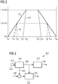
- Figure 2 shows three boost operational functions 110, 120, 130, which may be generated by the controller for operating the wind turbine 1 above nominal output power Pw.
- the three boost operational functions 110, 120, 130 are shown on a cartesian graph having an abscissa axis representing values of an operational variable and an ordinate axis representing values of output power (as a percentage of the nominal power output Pw of the wind turbine 1).
- the operational variable may be different according to the different embodiments of the present invention, as better clarified in the following.
- a boost power is generated according to a first boost operational function 110.
- the first boost operational function 110 is a crescent function of the operational variable between a first threshold Tv1 value and a second threshold value Tv2 of the operational variable.
- the operational variable is a wind speed, which may be a measured or an estimated value of the wind speed.
- the first boost operational function 110 is a crescent linear function of the wind speed.
- the power output reaches a predefined power boost level, which may be exceeding the nominal power Pw of a 10% (power output is 110% of the nominal power Pw).
- the first boost operational function 110 is a constant function of the wind speed between the second threshold Tv2 value and a third threshold value Tv3 of the wind speed and a decrescent function of the wind speed between the third threshold Tv3 value and a fourth threshold value Tv4 of the wind speed.
- the boost operational function 110 is a decrescent linear function of the wind speed between the third threshold Tv3 value and the fourth threshold value Tv4.
- the first boost operational function 110 is obtained at a constant pitch, by adjusting only the power output of the converter 21 according to a wind speed - dependent look-up table.
- the first boost operational function 110 may be obtained at a variable pitch.
- the operational variable may be a turbulence intensity or a pitch angle.
- a boost power is generated according to a second boost operational function 120.
- the second boost operational function 120 is a crescent function of a pitch angle between a first threshold Tv1' value and a second threshold value Tv2' of the pitch angle.
- the second boost operational function 120 is a crescent linear function of the pitch angle.
- the power output reaches a predefined power boost level, which may be exceeding the nominal power Pw of a 5% (power output is 105% of the nominal power Pw).
- the second boost operational function 120 is a constant function of the pitch angle between the second threshold Tv2' value and a third threshold value Tv3' of the pitch angle and a decrescent function of the pitch angle between the third threshold Tv3' value and a fourth threshold value Tv4' of the pitch angle.
- the second boost operational function 120 is a decrescent linear function of the pitch angle between the third threshold Tv3' value and the fourth threshold value Tv4'.
- the second boost operational function 120 is obtained at variable pitch, by operating accordingly the hydraulic pitch actuation circuit to generate a predefined pitch ranging between a pitch minimum, at the first threshold Tv1', and a pitch maximum, at the second threshold Tv2' .
- a boost power is generated according to a third boost operational function 130.
- the third boost operational function 130 is a crescent function of a pitch angle between a first threshold Tv1" value and a second threshold value Tv2 of the pitch angle.
- the third boost operational function 130 is a crescent linear function of the pitch angle.
- the power output reaches a predefined power boost level, which may be exceeding the nominal power Pw of a 10% (power output is 110% of the nominal power Pw).
- the third boost operational function 130 is a constant function of the pitch angle between the second threshold Tv2 value and a third threshold value Tv3 of the pitch angle and a decrescent function of the pitch angle between the third threshold Tv3 value and a fourth threshold value Tv4' of the pitch angle.
- the third boost operational function 130 is a decrescent linear function of the pitch angle between the third threshold Tv3 value and the fourth threshold value Tv4'.
- the third boost operational function 130 is obtained at variable pitch, by operating accordingly the hydraulic pitch actuation circuit to generate a predefined pitch ranging between a pitch minimum, at the first threshold Tv1", and a pitch maximum, at the second threshold Tv2.
- the first threshold Tv1, Tv1', Tv1" is chosen sufficiently high to not start boosting at a peak thrust where highest extreme loads and most fatigue loads occur.
- the second and the third boost operational functions 120, 130 may be obtained through a boosting circuit 200, represented in Figure 3 .
- the boosting circuit 200 can be implemented as a hardware circuit and/or a programmable logic circuit configured and arranged for implementing the specified operations/activities.
- the boosting circuit 200 may be included in the controller of the wind turbine 1.
- the boosting circuit 200 receives as input an enabling criteria command 210 (for example depending from the wind speed, so that the wind speed during boost operations is chosen sufficiently high to not start boosting at a peak thrust where highest extreme loads and most fatigue loads occur), a desired pitch angle 220 and a desired power reference 230.
- the boosting circuit 200 generates as output a pitch reference 240 and a boosted power reference 250.
- the boosting circuit 200 comprises a dynamic power boost block 260 which receives as input the enabling criteria command 210 and the desired pitch angle 220 and generates as output a dynamic power boost signal 265, which represents the percentage of desired boost, and boosted speed reference signal 290.
- the boosting circuit 200 comprises a speed-pitch controller 270 which receives as input the boosted speed reference signal 290 and generates as output the pitch reference 240.
- the boosting circuit 200 further comprises a speed-power controller 280 which receives as input a sum of the desired power reference 230 and the dynamic power boost signal 265 and generates as output the boosted power reference 250.
- the outputs of the boosting circuit 200 are then an increased power reference sent to the converter 21 and a pitch angle that accounts for the increase in desired speed which is sent to the the hydraulic pitch actuation circuit.
Landscapes
- Engineering & Computer Science (AREA)
- Life Sciences & Earth Sciences (AREA)
- Sustainable Development (AREA)
- Sustainable Energy (AREA)
- Chemical & Material Sciences (AREA)
- Combustion & Propulsion (AREA)
- Mechanical Engineering (AREA)
- General Engineering & Computer Science (AREA)
- Physics & Mathematics (AREA)
- Fluid Mechanics (AREA)
- Wind Motors (AREA)
Abstract
A method of controlling a wind turbine (1) comprises the step of boosting the output power of the wind turbine above the nominal power (Pw) of the wind turbine, according to a boost operational function (110, 120, 130) representing a boost level for the wind turbine (1). The boost operational function (110, 120, 130) is a crescent function of an operational variable at least between a first threshold (Tv1, Tv1', Tv1") value and a second threshold value (Tv2, Tv2') of the operational variable.
Description
- The present invention relates to the control of a wind turbine for power boosting or increasing of the operative power above the nominal power of the wind turbine.
- Wind turbines may provide power boost, i.e. the possibility to increase power over the nominal power value. The rotational speed is increased together with the power. Boost is configurable and may be set as default to a 5% of the nominal power. If the generator and converter capacity allow for it, the power boost can be increased to a higher number, for example 10% of the nominal power. This overcapacity may be for example used to boost power at high winds.
- According to a possible known implementation the bower boost is a step increase in power production when the pitch angle and the wind speed has reached above a predefined threshold. This is done to make sure that the power is not boosted at rated winds, where most extreme loads drive component design. By first boosting not at rated winds but just above where the loads have already lowered, the extreme loads will not be increased above their design levels by the additional speed and power production. The discrete jump in the power output determines two main problems:
- if the boost percentage changes, the pitch angle where boost is applied must be adapted as well. For example, if a power boost of 5% may be enabled at 6 degrees away from optimum pitch, a boost of 10% may only by applied at a pitch angle 12 degrees away from optimum pitch. By delaying the boost threshold, a lot of power is lost;
- when the boost is applied, the turbine blades pitch slightly into the wind to balance the increase in extracted electrical power to the extracted wind power. This extra pitch travel is not necessary and due to the high loading, it adds a lot to the cumulative structural damage in wind turbine components, such as the pitch bearings.
- Scope of the present invention is to provide a control method and circuit for controlling a wind turbine, in order to optimize the boosted power, resulting in an increased annual energy production (AEP), independently of wind distributions and without exceeding extreme structural capacity of blades, tower and other structural wind turbine components.
- This scope is met by the subject matter according to the independent claims. Advantageous embodiments of the present invention are described by the dependent claims.
- According to a first aspect of the present invention a method of controlling a wind turbine is provided, which comprises the step of boosting the output power of the wind turbine above the nominal power of the wind turbine, according to a boost operational function representing a boost level for the wind turbine, the boost operational function being a crescent function of an operational variable at least between a first threshold value and a second threshold value of the operational variable.
- According to a second aspect of the present invention, a controller for a wind turbine is provided, which includes a boosting circuit for boosting the output power of the wind turbine above the nominal power of the wind turbine, according to a boost operational function representing a boost level for the wind turbine. The boost operational function is a crescent function of an operational variable at least between a first threshold value and a second threshold value of the operational variable, the boosting circuit receiving as input:
- an enabling criteria command,
- a desired pitch angle, and
- a desired power reference,
- a pitch reference, and
- a boosted power reference representing the boost level for the wind turbine.
- In the context of the present invention, a "boosting circuit" can be implemented as a hardware circuit and/or a programmable logic circuit configured and arranged for implementing the specified operations/activities. In possible embodiments, a programmable circuit may include one or more computer circuits programmed to execute a set (or sets) of instructions (and/or configuration data). The instructions (and/or configuration data) can be in the form of firmware or software stored in and accessible from a memory. The "boosting circuit" may be part of the controller of the wind turbine.
- According to embodiments of the present invention, the boost operational function is a linear function of the operational variable at least between a first threshold value and a second threshold value. The boost operational function may be constant between the second threshold value and a third threshold value of the operational variable. The boost operational function may be decrescent between the third threshold value and a fourth threshold value of the operational variable.
- According to embodiments of the present invention, between the first threshold value and the second threshold value of the wind speed, the boost operational function is defined at constant pitch. Keeping constant the pitch angle when speed and power are boosted lowers the pitch bearing damage. Alternatively, the boost operational function is defined at crescent pitch angle ranging between the first threshold value and the second threshold value.
- According to another embodiment of the present invention, the pitch angle is kept constant between the first threshold value and the second threshold value and increased, for example linearly, between the second threshold value and the third threshold value, i.e. the dynamic boost increases the power by keeping the pitch angle constant until the maximum power output is achieved and, when the maximum is achieved, then the blades pitch out further if winds increase. This keeps the power and speed constant, thereby following the wind.
- Advantageously, by providing a dynamic boost instead of the discrete boost of the prior art, the present invention permits to significantly increase the AEP.
- It has to be noted that embodiments of the invention have been described with reference to different subject matters. In particular, some embodiments have been described with reference to apparatus type claims whereas other embodiments have been described with reference to method type claims. However, a person skilled in the art will gather from the above and the following description that, unless otherwise notified, in addition to any combination of features belonging to one type of subject-matter also any combination between features relating to different subject-matters, in particular between features of the apparatus type claims and features of the method type claims is considered as to be disclosed with this application.
- The aspects defined above and further aspects of the present invention are apparent from the examples of embodiment to be described hereinafter and are explained with reference to the examples of embodiment. The invention will be described in more detail hereinafter with reference to examples of embodiment but to which the invention is not limited.
- Figure 1
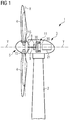
- shows a schematic section of a wind turbine to which the control method and circuit of the present invention can be applied for controlling power boost.
- Figure 2
- shows a graph illustrating showing how power boost according to the present invention is operated.
- Figure 3
- shows a schematic diagram representing a circuit for controlling power boost according to the present invention.
- The illustrations in the drawings are schematic. It is noted that in different figures, similar or identical elements are provided with the same reference signs.
-
Figure 1 shows awind turbine 1 according to the invention. Thewind turbine 1 comprises atower 2, which is mounted on a non-depicted foundation. Anacelle 3 is arranged on top of thetower 2. Thewind turbine 1 further comprises awind rotor 5 having at least one blade 4 (in the embodiment ofFigure 1 , the wind rotor comprises three blades 4, of which only two blades 4 are visible). Thewind rotor 5 is rotatable around a rotational axis Y. The blades 4 extend substantially radially with respect to the rotational axis Y and along a respective longitudinal axis X. - The
wind turbine 1 comprises anelectric generator 11, including astator 20 and arotor 30. Therotor 30 is rotatable with respect to thestator 20 about the rotational axis Y. Thewind rotor 5 is rotationally coupled with theelectric generator 11 either directly, e.g. direct drive or by means of a rotatablemain shaft 9 and/or through a gear box (not shown inFigure 1 ). A schematically depicted bearingassembly 8 is provided in order to hold in place themain shaft 9 and therotor 5. The rotatablemain shaft 9 extends along the rotational axis Y. - The
wind rotor 5 comprises threeflanges 15 for connecting a respective blade 4 to thewind rotor 5. A pitch bearing is interposed between eachblade flange 15 and the respective blade 4. A hydraulic pitch actuation circuit is associated to the pitch bearings of the blades 4 for regulating the pitch angle of each blade, i.e. the angular position of each blade about the respective blade longitudinal axis X. The hydraulic pitch actuation circuit may adjust all pitch angles on all rotor blades 4 at the same time and/or individual pitching of the rotor blades 4 may be available. On a rear side rear side of thenacelle 3, opposite to thewind rotor 5, aconverter 21 is provided. Thetransformer 21 is electrical connected to theelectrical generator 11 to transform the electrical output of thegenerator 11 to a certain predetermined power output at a predetermined voltage level to be provided to an electrical network, which is electrically connected to thetransformer 21. - The
wind turbine 1 comprises a controller (not shown) with a processor and a memory. The processor executes computing tasks based on instructions stored in the memory. According to such tasks, the wind turbine in operation generates a requested power output level. In particular, the power output level may be a boost power, i.e. having a value greater than a nominal output power Pw of thewind turbine 1. This may be obtained by adjusting the pitch angle by operating accordingly the hydraulic pitch actuation circuit associated to the pitch bearings of the blades 4. Alternatively, the requested power output level may be obtained by adjusting the power output of theconverter 21. -
Figure 2 shows three boostoperational functions wind turbine 1 above nominal output power Pw. The three boostoperational functions - According to a first embodiment of the invention, a boost power is generated according to a first boost
operational function 110. The first boostoperational function 110 is a crescent function of the operational variable between a first threshold Tv1 value and a second threshold value Tv2 of the operational variable. The operational variable is a wind speed, which may be a measured or an estimated value of the wind speed. In particular, the first boostoperational function 110 is a crescent linear function of the wind speed. At the second threshold value Tv2 the power output reaches a predefined power boost level, which may be exceeding the nominal power Pw of a 10% (power output is 110% of the nominal power Pw). The first boostoperational function 110 is a constant function of the wind speed between the second threshold Tv2 value and a third threshold value Tv3 of the wind speed and a decrescent function of the wind speed between the third threshold Tv3 value and a fourth threshold value Tv4 of the wind speed. In particular, the boostoperational function 110 is a decrescent linear function of the wind speed between the third threshold Tv3 value and the fourth threshold value Tv4. The first boostoperational function 110 is obtained at a constant pitch, by adjusting only the power output of theconverter 21 according to a wind speed - dependent look-up table. According to another embodiment of the present invention, the first boostoperational function 110 may be obtained at a variable pitch. - According to other embodiments of the present invention, the operational variable may be a turbulence intensity or a pitch angle.
- According to a second embodiment of the invention, a boost power is generated according to a second boost
operational function 120. The second boostoperational function 120 is a crescent function of a pitch angle between a first threshold Tv1' value and a second threshold value Tv2' of the pitch angle. In particular, the second boostoperational function 120 is a crescent linear function of the pitch angle. At the second threshold value Tv2' the power output reaches a predefined power boost level, which may be exceeding the nominal power Pw of a 5% (power output is 105% of the nominal power Pw). The second boostoperational function 120 is a constant function of the pitch angle between the second threshold Tv2' value and a third threshold value Tv3' of the pitch angle and a decrescent function of the pitch angle between the third threshold Tv3' value and a fourth threshold value Tv4' of the pitch angle. In particular, the second boostoperational function 120 is a decrescent linear function of the pitch angle between the third threshold Tv3' value and the fourth threshold value Tv4'. The second boostoperational function 120 is obtained at variable pitch, by operating accordingly the hydraulic pitch actuation circuit to generate a predefined pitch ranging between a pitch minimum, at the first threshold Tv1', and a pitch maximum, at the second threshold Tv2' . - According to a third embodiment of the invention, a boost power is generated according to a third boost
operational function 130. The third boostoperational function 130 is a crescent function of a pitch angle between a first threshold Tv1" value and a second threshold value Tv2 of the pitch angle. In particular, the third boostoperational function 130 is a crescent linear function of the pitch angle. At the second threshold value Tv2 the power output reaches a predefined power boost level, which may be exceeding the nominal power Pw of a 10% (power output is 110% of the nominal power Pw). The third boostoperational function 130 is a constant function of the pitch angle between the second threshold Tv2 value and a third threshold value Tv3 of the pitch angle and a decrescent function of the pitch angle between the third threshold Tv3 value and a fourth threshold value Tv4' of the pitch angle. In particular, the third boostoperational function 130 is a decrescent linear function of the pitch angle between the third threshold Tv3 value and the fourth threshold value Tv4'. Similarly to the second boostoperational function 120, the third boostoperational function 130 is obtained at variable pitch, by operating accordingly the hydraulic pitch actuation circuit to generate a predefined pitch ranging between a pitch minimum, at the first threshold Tv1", and a pitch maximum, at the second threshold Tv2. - The first threshold Tv1, Tv1', Tv1" is chosen sufficiently high to not start boosting at a peak thrust where highest extreme loads and most fatigue loads occur.
- The second and the third boost
operational functions circuit 200, represented inFigure 3 . The boostingcircuit 200 can be implemented as a hardware circuit and/or a programmable logic circuit configured and arranged for implementing the specified operations/activities. The boostingcircuit 200 may be included in the controller of thewind turbine 1. The boostingcircuit 200 receives as input an enabling criteria command 210 (for example depending from the wind speed, so that the wind speed during boost operations is chosen sufficiently high to not start boosting at a peak thrust where highest extreme loads and most fatigue loads occur), a desiredpitch angle 220 and a desiredpower reference 230. The boostingcircuit 200 generates as output apitch reference 240 and a boostedpower reference 250. The boostingcircuit 200 comprises a dynamicpower boost block 260 which receives as input the enabling criteria command 210 and the desiredpitch angle 220 and generates as output a dynamicpower boost signal 265, which represents the percentage of desired boost, and boostedspeed reference signal 290. The boostingcircuit 200 comprises a speed-pitch controller 270 which receives as input the boostedspeed reference signal 290 and generates as output thepitch reference 240. The boostingcircuit 200 further comprises a speed-power controller 280 which receives as input a sum of the desiredpower reference 230 and the dynamicpower boost signal 265 and generates as output the boostedpower reference 250. The outputs of the boostingcircuit 200 are then an increased power reference sent to theconverter 21 and a pitch angle that accounts for the increase in desired speed which is sent to the the hydraulic pitch actuation circuit.
Claims (9)
- A method of controlling a wind turbine (1) comprising the step of boosting the output power of the wind turbine above the nominal power (Pw) of the wind turbine, according to a boost operational function (110, 120, 130) representing a boost level for the wind turbine (1), the boost operational function (110, 120, 130) being a crescent function of an operational variable at least between a first threshold (Tv1, Tv1', Tv1") value and a second threshold value (Tv2, Tv2') of the operational variable.
- The method according to claim 1, wherein the boost operational function (110, 120, 130) is a linear function of the operational variable at least between a first threshold (Tv1, Tv1', Tv1") value and a second threshold value (Tv2, Tv2') of the operational variable.
- The method according to claim 1 or 2, wherein the boost operational function (110, 120, 130) is constant between the second threshold value (Tv2, Tv2') and a third threshold value (Tv3, Tv3') of the operational variable.
- The method according to any of the preceding claims, wherein the boost operational function (110, 120, 130) is decrescent the third threshold value (Tv3, Tv3') and a fourth threshold value (Tv4, Tv4', Tv4") of the operational variable.
- The method according to any of the preceding claims, wherein the boost operational function (110, 120, 130) is defined at constant pitch between the first threshold (Tv1, Tv1', Tv1") value and the second threshold value (Tv2, Tv2') .
- The method according to any of the preceding claims, wherein the boost operational function (110, 120, 130) is defined at crescent pitch between the first threshold (Tv1, Tv1', Tv1") value and the second threshold value (Tv2, Tv2') .
- The method according to any of the preceding claims, wherein the operational variable is a pitch angle, or a wind speed or a turbulence intensity.
- The method according to claim 7, wherein the first boost operational function (110) is obtained at a constant pitch, by adjusting the output power according to a wind speed - dependent look-up table.
- A controller for a wind turbine (1) including a boosting circuit (200) for boosting the output power of the wind turbine above the nominal power (Pw) of the wind turbine, according to a boost operational function (110, 120, 130) representing a boost level for the wind turbine (1), the boost operational function being a crescent function of an operational variable at least between a first threshold (Tv1, Tv1', Tv1") value and a second threshold value (Tv2, Tv2') of the operational variable, the boosting circuit (200) receiving as input:an enabling criteria command (210),a desired pitch angle (220), anda desired power reference (230),the boosting circuit (200) producing as output:a pitch reference (240), anda boosted power reference (250) representing the boost level for the wind turbine (1).
Priority Applications (7)
| Application Number | Priority Date | Filing Date | Title |
|---|---|---|---|
| EP19197508.5A EP3792482A1 (en) | 2019-09-16 | 2019-09-16 | Power boost for a wind turbine |
| DK20754626.8T DK3987173T3 (en) | 2019-09-16 | 2020-07-22 | POWER INCREASE FOR A WINDMILL |
| CN202080064861.XA CN114402138A (en) | 2019-09-16 | 2020-07-22 | Power boost for wind turbines |
| PCT/EP2020/070682 WO2021052655A1 (en) | 2019-09-16 | 2020-07-22 | Power boost for a wind turbine |
| US17/641,141 US20220282701A1 (en) | 2019-09-16 | 2020-07-22 | Power boost for a wind turbine |
| ES20754626T ES2963541T3 (en) | 2019-09-16 | 2020-07-22 | Power increase for a wind turbine |
| EP20754626.8A EP3987173B1 (en) | 2019-09-16 | 2020-07-22 | Power boost for a wind turbine |
Applications Claiming Priority (1)
| Application Number | Priority Date | Filing Date | Title |
|---|---|---|---|
| EP19197508.5A EP3792482A1 (en) | 2019-09-16 | 2019-09-16 | Power boost for a wind turbine |
Publications (1)
| Publication Number | Publication Date |
|---|---|
| EP3792482A1 true EP3792482A1 (en) | 2021-03-17 |
Family
ID=67981935
Family Applications (2)
| Application Number | Title | Priority Date | Filing Date |
|---|---|---|---|
| EP19197508.5A Withdrawn EP3792482A1 (en) | 2019-09-16 | 2019-09-16 | Power boost for a wind turbine |
| EP20754626.8A Active EP3987173B1 (en) | 2019-09-16 | 2020-07-22 | Power boost for a wind turbine |
Family Applications After (1)
| Application Number | Title | Priority Date | Filing Date |
|---|---|---|---|
| EP20754626.8A Active EP3987173B1 (en) | 2019-09-16 | 2020-07-22 | Power boost for a wind turbine |
Country Status (6)
| Country | Link |
|---|---|
| US (1) | US20220282701A1 (en) |
| EP (2) | EP3792482A1 (en) |
| CN (1) | CN114402138A (en) |
| DK (1) | DK3987173T3 (en) |
| ES (1) | ES2963541T3 (en) |
| WO (1) | WO2021052655A1 (en) |
Cited By (1)
| Publication number | Priority date | Publication date | Assignee | Title |
|---|---|---|---|---|
| EP4358380A1 (en) | 2022-10-21 | 2024-04-24 | Siemens Gamesa Renewable Energy A/S | Boosting wind turbine power output |
Citations (5)
| Publication number | Priority date | Publication date | Assignee | Title |
|---|---|---|---|---|
| WO2014048583A1 (en) * | 2012-09-28 | 2014-04-03 | Siemens Aktiengesellschaft | Method and arrangement for controlling a wind turbine |
| EP2868918A1 (en) * | 2013-10-31 | 2015-05-06 | General Electric Company | System and method for controlling a wind turbine |
| WO2016058617A1 (en) * | 2014-10-17 | 2016-04-21 | Vestas Wind Systems A/S | Control of wind turbines |
| US20170356420A1 (en) * | 2014-11-24 | 2017-12-14 | Vestas Wind Systems A/S | Over-rating control of a wind turbine generator |
| US20180156197A1 (en) * | 2015-06-30 | 2018-06-07 | Vestas Wind Systems A/S | Control method and system for protection of wind turbines |
Family Cites Families (2)
| Publication number | Priority date | Publication date | Assignee | Title |
|---|---|---|---|---|
| DK201170539A (en) * | 2011-09-30 | 2013-03-31 | Vestas Wind Sys As | Control of wind turbines |
| DE102015203841A1 (en) * | 2015-03-04 | 2016-09-08 | Wobben Properties Gmbh | Method for operating a wind energy plant |
-
2019
- 2019-09-16 EP EP19197508.5A patent/EP3792482A1/en not_active Withdrawn
-
2020
- 2020-07-22 CN CN202080064861.XA patent/CN114402138A/en active Pending
- 2020-07-22 ES ES20754626T patent/ES2963541T3/en active Active
- 2020-07-22 WO PCT/EP2020/070682 patent/WO2021052655A1/en unknown
- 2020-07-22 US US17/641,141 patent/US20220282701A1/en active Pending
- 2020-07-22 DK DK20754626.8T patent/DK3987173T3/en active
- 2020-07-22 EP EP20754626.8A patent/EP3987173B1/en active Active
Patent Citations (5)
| Publication number | Priority date | Publication date | Assignee | Title |
|---|---|---|---|---|
| WO2014048583A1 (en) * | 2012-09-28 | 2014-04-03 | Siemens Aktiengesellschaft | Method and arrangement for controlling a wind turbine |
| EP2868918A1 (en) * | 2013-10-31 | 2015-05-06 | General Electric Company | System and method for controlling a wind turbine |
| WO2016058617A1 (en) * | 2014-10-17 | 2016-04-21 | Vestas Wind Systems A/S | Control of wind turbines |
| US20170356420A1 (en) * | 2014-11-24 | 2017-12-14 | Vestas Wind Systems A/S | Over-rating control of a wind turbine generator |
| US20180156197A1 (en) * | 2015-06-30 | 2018-06-07 | Vestas Wind Systems A/S | Control method and system for protection of wind turbines |
Cited By (2)
| Publication number | Priority date | Publication date | Assignee | Title |
|---|---|---|---|---|
| EP4358380A1 (en) | 2022-10-21 | 2024-04-24 | Siemens Gamesa Renewable Energy A/S | Boosting wind turbine power output |
| WO2024083556A1 (en) | 2022-10-21 | 2024-04-25 | Siemens Gamesa Renewable Energy A/S | Boosting wind turbine power output |
Also Published As
| Publication number | Publication date |
|---|---|
| DK3987173T3 (en) | 2023-11-20 |
| EP3987173A1 (en) | 2022-04-27 |
| ES2963541T3 (en) | 2024-03-27 |
| CN114402138A (en) | 2022-04-26 |
| US20220282701A1 (en) | 2022-09-08 |
| EP3987173B1 (en) | 2023-09-06 |
| WO2021052655A1 (en) | 2021-03-25 |
Similar Documents
| Publication | Publication Date | Title |
|---|---|---|
| CN100371585C (en) | Control system for wind turbine with hydrodynamic transmission | |
| EP2872775B1 (en) | Method and arrangement for controlling a wind turbine | |
| US8793027B2 (en) | Power curtailment of wind turbines | |
| EP2565442A1 (en) | System and method for operating a wind turbine using adaptive reference variables | |
| US20090021014A1 (en) | Wind energy installation with an extended rotation speed range | |
| US20190072072A1 (en) | Variable speed control of wind turbine generator based on estimated torque | |
| CN109072871B (en) | Method for operating a wind turbine | |
| WO2013132635A1 (en) | Output control device and output control method for windmill | |
| EP3318751A1 (en) | Damping mechanical oscillations of a wind turbine | |
| US20170082090A1 (en) | System for installing a cable in a tower of a wind turbine and method therefor | |
| US10273938B2 (en) | Ramping power in a wind turbine dependent on an estimated available wind power | |
| EP2113659A2 (en) | Method of operation of a wind turbine which minimises the oscillations of the tower | |
| US11879432B2 (en) | Controller and control method for a wind turbine | |
| EP3987173B1 (en) | Power boost for a wind turbine | |
| EP2527643A2 (en) | Wind turbine control methods and systems for cold climate and low altitude conditions | |
| EP2594786A1 (en) | Method of operating a wind turbine | |
| CN114423941A (en) | Control device and method for controlling a wind turbine | |
| CN115467778A (en) | Method for controlling rotor speed of a wind turbine | |
| EP4295034B1 (en) | Controlling a wind turbine regarding noise emission | |
| US20230175485A1 (en) | Wind turbine control arrangement | |
| US11905931B2 (en) | Controller for a wind turbine | |
| US12071933B2 (en) | Method for operating a wind power plant | |
| US20220397091A1 (en) | Pivot angle control of blades of a wind turbine with hinged blades | |
| US20240093669A1 (en) | Method and system for optimizing power output of a wind turbine with yaw misalignment | |
| EP3633188A1 (en) | Variable flow hydraulic circuit for a wind turbine |
Legal Events
| Date | Code | Title | Description |
|---|---|---|---|
| PUAI | Public reference made under article 153(3) epc to a published international application that has entered the european phase |
Free format text: ORIGINAL CODE: 0009012 |
|
| STAA | Information on the status of an ep patent application or granted ep patent |
Free format text: STATUS: THE APPLICATION HAS BEEN PUBLISHED |
|
| AK | Designated contracting states |
Kind code of ref document: A1 Designated state(s): AL AT BE BG CH CY CZ DE DK EE ES FI FR GB GR HR HU IE IS IT LI LT LU LV MC MK MT NL NO PL PT RO RS SE SI SK SM TR |
|
| STAA | Information on the status of an ep patent application or granted ep patent |
Free format text: STATUS: THE APPLICATION IS DEEMED TO BE WITHDRAWN |
|
| 18D | Application deemed to be withdrawn |
Effective date: 20210918 |