EP2868918A1 - System and method for controlling a wind turbine - Google Patents
System and method for controlling a wind turbine Download PDFInfo
- Publication number
- EP2868918A1 EP2868918A1 EP14190166.0A EP14190166A EP2868918A1 EP 2868918 A1 EP2868918 A1 EP 2868918A1 EP 14190166 A EP14190166 A EP 14190166A EP 2868918 A1 EP2868918 A1 EP 2868918A1
- Authority
- EP
- European Patent Office
- Prior art keywords
- wind turbine
- power output
- life
- anticipated
- turbine
- Prior art date
- Legal status (The legal status is an assumption and is not a legal conclusion. Google has not performed a legal analysis and makes no representation as to the accuracy of the status listed.)
- Granted
Links
- 238000000034 method Methods 0.000 title claims abstract description 48
- 230000003466 anti-cipated effect Effects 0.000 claims abstract description 56
- 230000003247 decreasing effect Effects 0.000 claims abstract description 16
- 238000004458 analytical method Methods 0.000 claims description 11
- 238000012544 monitoring process Methods 0.000 claims description 11
- 230000007423 decrease Effects 0.000 claims description 6
- 230000006870 function Effects 0.000 description 9
- 230000001276 controlling effect Effects 0.000 description 8
- 230000007246 mechanism Effects 0.000 description 7
- 230000009467 reduction Effects 0.000 description 7
- 238000005452 bending Methods 0.000 description 5
- 230000015556 catabolic process Effects 0.000 description 5
- 238000006731 degradation reaction Methods 0.000 description 5
- 230000000875 corresponding effect Effects 0.000 description 4
- 238000013461 design Methods 0.000 description 4
- 238000005259 measurement Methods 0.000 description 4
- 230000007704 transition Effects 0.000 description 4
- 238000004891 communication Methods 0.000 description 3
- 238000010586 diagram Methods 0.000 description 3
- 238000009826 distribution Methods 0.000 description 3
- 230000008859 change Effects 0.000 description 2
- 238000012986 modification Methods 0.000 description 2
- 230000004048 modification Effects 0.000 description 2
- 238000011144 upstream manufacturing Methods 0.000 description 2
- 230000000052 comparative effect Effects 0.000 description 1
- 238000007796 conventional method Methods 0.000 description 1
- 230000002596 correlated effect Effects 0.000 description 1
- 230000003111 delayed effect Effects 0.000 description 1
- 230000000694 effects Effects 0.000 description 1
- 230000005611 electricity Effects 0.000 description 1
- 238000005516 engineering process Methods 0.000 description 1
- 210000003746 feather Anatomy 0.000 description 1
- 238000004519 manufacturing process Methods 0.000 description 1
- 239000000463 material Substances 0.000 description 1
- 239000002574 poison Substances 0.000 description 1
- 231100000614 poison Toxicity 0.000 description 1
- 238000012545 processing Methods 0.000 description 1
- 230000004044 response Effects 0.000 description 1
Images


Classifications
-
- F—MECHANICAL ENGINEERING; LIGHTING; HEATING; WEAPONS; BLASTING
- F03—MACHINES OR ENGINES FOR LIQUIDS; WIND, SPRING, OR WEIGHT MOTORS; PRODUCING MECHANICAL POWER OR A REACTIVE PROPULSIVE THRUST, NOT OTHERWISE PROVIDED FOR
- F03D—WIND MOTORS
- F03D7/00—Controlling wind motors
- F03D7/02—Controlling wind motors the wind motors having rotation axis substantially parallel to the air flow entering the rotor
- F03D7/028—Controlling wind motors the wind motors having rotation axis substantially parallel to the air flow entering the rotor controlling wind motor output power
-
- F—MECHANICAL ENGINEERING; LIGHTING; HEATING; WEAPONS; BLASTING
- F03—MACHINES OR ENGINES FOR LIQUIDS; WIND, SPRING, OR WEIGHT MOTORS; PRODUCING MECHANICAL POWER OR A REACTIVE PROPULSIVE THRUST, NOT OTHERWISE PROVIDED FOR
- F03D—WIND MOTORS
- F03D17/00—Monitoring or testing of wind motors, e.g. diagnostics
-
- F—MECHANICAL ENGINEERING; LIGHTING; HEATING; WEAPONS; BLASTING
- F03—MACHINES OR ENGINES FOR LIQUIDS; WIND, SPRING, OR WEIGHT MOTORS; PRODUCING MECHANICAL POWER OR A REACTIVE PROPULSIVE THRUST, NOT OTHERWISE PROVIDED FOR
- F03D—WIND MOTORS
- F03D7/00—Controlling wind motors
- F03D7/02—Controlling wind motors the wind motors having rotation axis substantially parallel to the air flow entering the rotor
- F03D7/028—Controlling wind motors the wind motors having rotation axis substantially parallel to the air flow entering the rotor controlling wind motor output power
- F03D7/0292—Controlling wind motors the wind motors having rotation axis substantially parallel to the air flow entering the rotor controlling wind motor output power to reduce fatigue
-
- F—MECHANICAL ENGINEERING; LIGHTING; HEATING; WEAPONS; BLASTING
- F03—MACHINES OR ENGINES FOR LIQUIDS; WIND, SPRING, OR WEIGHT MOTORS; PRODUCING MECHANICAL POWER OR A REACTIVE PROPULSIVE THRUST, NOT OTHERWISE PROVIDED FOR
- F03D—WIND MOTORS
- F03D80/00—Details, components or accessories not provided for in groups F03D1/00 - F03D17/00
- F03D80/80—Arrangement of components within nacelles or towers
- F03D80/82—Arrangement of components within nacelles or towers of electrical components
-
- F—MECHANICAL ENGINEERING; LIGHTING; HEATING; WEAPONS; BLASTING
- F03—MACHINES OR ENGINES FOR LIQUIDS; WIND, SPRING, OR WEIGHT MOTORS; PRODUCING MECHANICAL POWER OR A REACTIVE PROPULSIVE THRUST, NOT OTHERWISE PROVIDED FOR
- F03D—WIND MOTORS
- F03D9/00—Adaptations of wind motors for special use; Combinations of wind motors with apparatus driven thereby; Wind motors specially adapted for installation in particular locations
- F03D9/20—Wind motors characterised by the driven apparatus
- F03D9/25—Wind motors characterised by the driven apparatus the apparatus being an electrical generator
-
- F—MECHANICAL ENGINEERING; LIGHTING; HEATING; WEAPONS; BLASTING
- F03—MACHINES OR ENGINES FOR LIQUIDS; WIND, SPRING, OR WEIGHT MOTORS; PRODUCING MECHANICAL POWER OR A REACTIVE PROPULSIVE THRUST, NOT OTHERWISE PROVIDED FOR
- F03D—WIND MOTORS
- F03D15/00—Transmission of mechanical power
- F03D15/10—Transmission of mechanical power using gearing not limited to rotary motion, e.g. with oscillating or reciprocating members
-
- F—MECHANICAL ENGINEERING; LIGHTING; HEATING; WEAPONS; BLASTING
- F03—MACHINES OR ENGINES FOR LIQUIDS; WIND, SPRING, OR WEIGHT MOTORS; PRODUCING MECHANICAL POWER OR A REACTIVE PROPULSIVE THRUST, NOT OTHERWISE PROVIDED FOR
- F03D—WIND MOTORS
- F03D80/00—Details, components or accessories not provided for in groups F03D1/00 - F03D17/00
- F03D80/70—Bearing or lubricating arrangements
-
- F—MECHANICAL ENGINEERING; LIGHTING; HEATING; WEAPONS; BLASTING
- F05—INDEXING SCHEMES RELATING TO ENGINES OR PUMPS IN VARIOUS SUBCLASSES OF CLASSES F01-F04
- F05B—INDEXING SCHEME RELATING TO WIND, SPRING, WEIGHT, INERTIA OR LIKE MOTORS, TO MACHINES OR ENGINES FOR LIQUIDS COVERED BY SUBCLASSES F03B, F03D AND F03G
- F05B2270/00—Control
- F05B2270/10—Purpose of the control system
- F05B2270/20—Purpose of the control system to optimise the performance of a machine
-
- F—MECHANICAL ENGINEERING; LIGHTING; HEATING; WEAPONS; BLASTING
- F05—INDEXING SCHEMES RELATING TO ENGINES OR PUMPS IN VARIOUS SUBCLASSES OF CLASSES F01-F04
- F05B—INDEXING SCHEME RELATING TO WIND, SPRING, WEIGHT, INERTIA OR LIKE MOTORS, TO MACHINES OR ENGINES FOR LIQUIDS COVERED BY SUBCLASSES F03B, F03D AND F03G
- F05B2270/00—Control
- F05B2270/30—Control parameters, e.g. input parameters
- F05B2270/332—Maximum loads or fatigue criteria
-
- Y—GENERAL TAGGING OF NEW TECHNOLOGICAL DEVELOPMENTS; GENERAL TAGGING OF CROSS-SECTIONAL TECHNOLOGIES SPANNING OVER SEVERAL SECTIONS OF THE IPC; TECHNICAL SUBJECTS COVERED BY FORMER USPC CROSS-REFERENCE ART COLLECTIONS [XRACs] AND DIGESTS
- Y02—TECHNOLOGIES OR APPLICATIONS FOR MITIGATION OR ADAPTATION AGAINST CLIMATE CHANGE
- Y02E—REDUCTION OF GREENHOUSE GAS [GHG] EMISSIONS, RELATED TO ENERGY GENERATION, TRANSMISSION OR DISTRIBUTION
- Y02E10/00—Energy generation through renewable energy sources
- Y02E10/70—Wind energy
- Y02E10/72—Wind turbines with rotation axis in wind direction
Definitions
- the present subject matter relates generally to wind turbines and, more particularly, to a system and method for controlling a wind turbine in a manner that provides for increased power output over an early portion of the turbine's operating life without resulting in a reduction in the overall operating life of the turbine.
- a modem wind turbine typically includes a tower, generator, gearbox, nacelle, and one or more rotor blades.
- the rotor blades are the primary elements for converting wind energy into electrical energy.
- the blades typically have the cross-sectional profile of an airfoil such that, during operation, air flows over the blade producing a pressure difference between its sides. Consequently, a lift force, which is directed from the pressure side towards the suction side, acts on the blade. The lift force generates torque on the main rotor shaft, which is geared to a generator for producing electricity.
- a wind turbine is designed to operate at its rated power output over a predetermined or anticipated operating life.
- this anticipated operating life is limited by or based upon the anticipated component life of one or more of the wind turbine components (referred to herein as "life-limiting components").
- FIG. 1 illustrates example data for a conventional wind turbine having an anticipated operating life 100 (ending at dashed line 102) that is defined by the anticipated component life (indicated by component life curve 104) of one or more of its life-limiting components.
- FIG. 1 illustrates example data for a conventional wind turbine having an anticipated operating life 100 (ending at dashed line 102) that is defined by the anticipated component life (indicated by component life curve 104) of one or more of its life-limiting components.
- the remaining component life for its life-limiting component(s) decreases linearly along the component life curve 104 from 100% at the wind turbine's initial start-up to about 50% at the midpoint of the turbine's anticipated life (indicated by point 108) and then to about 0% at the end 102 of the turbine's anticipated operating life 100.
- the anticipated operating life 100 for the turbine is defined by the anticipated operating life of such life-limiting component(s).
- the rated power output associated with each wind turbine is well below the instantaneous maximum power output that may be achieved.
- uprating results in increased loading on the wind turbine components, thereby reducing component lives.
- uprating the wind turbine can significantly reduce its overall operating life.
- the present subject matter is directed to a method for controlling a wind turbine.
- the method may generally include operating the wind turbine at an initial power output that is greater than a rated power output associated with the wind turbine.
- the wind turbine may have an anticipated operational life at the rated power output.
- the method may include decreasing a power output of the wind turbine over time in order to maintain an actual operating life of the wind turbine substantially equal to or greater than the anticipated operational life.
- a final power output of the wind turbine at an end of the anticipated operating life may be less than the rated power output.
- the present subject matter is directed to a system including a wind turbine and a controller configured to control the operation of the wind turbine.
- the wind turbine may be associated with a rated power output and may have an anticipated operating life at the rated power output.
- the controller may be configured to operate the wind turbine at an initial power output that is greater than the rated power output. Additionally, the controller may be further configured to decrease a power output of the wind turbine over time in order to maintain an actual operating life of the wind turbine substantially equal to or greater than the anticipated operational life. Moreover, a final power output of the wind turbine at an end of the anticipated operating life may be less than the rated power output.
- the present subject matter is directed to a system and method for controlling a wind turbine.
- the disclosed system and method provide for a wind turbine to be operated at an initial power output that exceeds its rated power output for an early portion of the turbine's operating life.
- the power output may be decreased from the initial power output in order to maintain the actual operating life of the wind turbine at or above its anticipated operating life.
- the wind turbine may be operated at a heightened power output (i.e., above its rated power output) over a first portion of the turbine's operating life in order to increase its power output and at a reduced power output (i.e., below its rated power output) for a second portion of the turbine's operating life in order to maintain the actual operating life of the wind turbine substantially equal to or greater than its anticipated operating life.
- a heightened power output i.e., above its rated power output
- a reduced power output i.e., below its rated power output
- the wind turbine 10 generally includes a tower 12 extending from a support surface 14, a nacelle 16 mounted on the tower 12, and a rotor 18 coupled to the nacelle 16.
- the rotor 18 includes a rotatable hub 20 and at least one rotor blade 22 coupled to and extending outwardly from the hub 20.
- the rotor 18 includes three rotor blades 22.
- the rotor 18 may include more or less than three rotor blades 22.
- Each rotor blade 22 may be spaced about the hub 20 to facilitate rotating the rotor 18 to enable kinetic energy to be transferred from the wind into usable mechanical energy, and subsequently, electrical energy.
- the hub 20 may be rotatably coupled to an electric generator 24 ( FIG. 3 ) positioned within the nacelle 16 to permit electrical energy to be produced.
- the wind turbine 10 may also include a turbine control system or turbine controller 26 centralized within the nacelle 16 (or disposed at any other suitable location within and/or relative to the wind turbine 10).
- the turbine controller 26 may comprise a computer or other suitable processing unit.
- the turbine controller 26 may include suitable computer-readable instructions that, when implemented, configure the controller 26 to perform various different functions, such as receiving, transmitting and/or executing wind turbine control signals.
- the turbine controller 26 may generally be configured to control the various operating modes (e.g., start-up or shut-down sequences) and/or components of the wind turbine 10.
- the controller 26 may be configured to adjust the blade pitch or pitch angle of each rotor blade 22 (i.e., an angle that determines a perspective of the blade 22 with respect to the direction of the wind) about its pitch axis 28 in order to control the rotational speed of the rotor blade 22 and/or the power output generated by the wind turbine 10.
- the turbine controller 26 may control the pitch angle of the rotor blades 22, either individually or simultaneously, by transmitting suitable control signals to one or more pitch drives or pitch adjustment mechanisms 32 ( FIG. 3 ) of the wind turbine 10.
- a generator 24 may be disposed within the nacelle 16.
- the generator 24 may be coupled to the rotor 18 for producing electrical power from the rotational energy generated by the rotor 18.
- the rotor 18 may include a rotor shaft 38 coupled to the hub 20 for rotation therewith.
- the rotor shaft 38 may, in turn, be rotatably coupled to a generator shaft 40 of the generator 24 through a gearbox 42.
- the rotor shaft 38 may provide a low speed, high torque input to the gearbox 42 in response to rotation of the rotor blades 22 and the hub 20.
- the gearbox 42 may then be configured to convert the low speed, high torque input to a high speed, low torque output to drive the generator shaft 40 and, thus, the generator 24.
- the controller 26 may also be located within the nacelle 16 (e.g., within a control box or panel). However, in other embodiments, the controller 26 may be located within any other component of the wind turbine 10 or at a location outside the wind turbine (e.g., when the controller 26 is configured as a farm controller for controlling a plurality of wind turbines). As is generally understood, the controller 26 may be communicatively coupled to any number of the components of the wind turbine 10 in order to control the operation of such components. For example, as indicated above, the controller 26 may be communicatively coupled to each pitch adjustment mechanism 32 of the wind turbine 10 (one for each rotor blade 22) via a pitch controller 30 to facilitate rotation of each rotor blade 22 about its pitch axis 28.
- each pitch adjustment mechanism 32 may include any suitable components and may have any suitable configuration that allows the pitch adjustment mechanism 32 to function as described herein.
- each pitch adjustment mechanism 32 may include a pitch drive motor 44 (e.g., any suitable electric motor), a pitch drive gearbox 46, and a pitch drive pinion 48.
- the pitch drive motor 44 may be coupled to the pitch drive gearbox 46 so that the pitch drive motor 44 imparts mechanical force to the pitch drive gearbox 46.
- the pitch drive gearbox 46 may be coupled to the pitch drive pinion 48 for rotation therewith.
- the pitch drive pinion 48 may, in turn, be in rotational engagement with a pitch bearing 50 coupled between the hub 20 and a corresponding rotor blade 22 such that rotation of the pitch drive pinion 48 causes rotation of the pitch bearing 50.
- rotation of the pitch drive motor 44 drives the pitch drive gearbox 46 and the pitch drive pinion 48, thereby rotating the pitch bearing 50 and the rotor blade 22 about the pitch axis 28.
- each pitch adjustment mechanism 32 may have any other suitable configuration that facilitates rotation of a rotor blade 22 about its pitch axis 28.
- the wind turbine 10 may also include one or more sensors for monitoring various operating conditions of the wind turbine 10.
- the wind turbine 10 may include one or more shaft sensors 60 configured to monitor one or more shaft-related operating conditions of the wind turbine 10, such as the loads acting on the rotor shaft 38 (e.g., thrust, bending and/or torque loads), the deflection of the rotor shaft 38 (e.g., including shaft bending), the rotational speed of the rotor shaft 38 and/or the like.
- the wind turbine may also include one or more blades sensors 62 ( FIGS.
- the wind turbine 10 may include one or more generator sensors 64 configured to monitor one or more generator-related operating conditions of the wind turbine 10, such as the power output of the generator 24, the rotational speed of the generator 24, the generator torque and/or the like.
- the wind turbine 10 may also include various other sensors for monitoring numerous other turbine operating conditions.
- the wind turbine 10 may include one or more tower sensors 66 for monitoring various tower-related operating conditions, such as the loads acting the tower 12, the deflection of the tower 12 (e.g., tower bending and/or twisting), tower vibrations and/or the like.
- the wind turbine 10 may include one or more wind sensors 68 for monitoring one or more wind conditions of the wind turbine 10, such as the wind speed, the wind direction, the turbulence or turbulence intensity of the wind and/or the like.
- the wind turbine 10 may include one or more hub sensors 70 for monitoring various hub-related operating conditions (e.g., the loads transmitted through the hub 20, hub vibrations and/or the like), one or more nacelle sensors 72 for monitoring one or more nacelle-related operating conditions (e.g., the loads transmitted through the nacelle 16, nacelle vibrations and/or the like) and/or one or more gearbox sensors 74 for monitoring one or more gearbox-related operating conditions (e.g., gearbox torque, gearbox loading, rotational speeds within the gearbox and/or the like).
- the wind turbine 10 may further include various other suitable sensors for monitoring any other suitable operating conditions of the wind turbine 10. It should be appreciated that the various sensors described herein may correspond to pre-existing sensors of a wind turbine 10 and/or sensors that have been specifically installed within the wind turbine 10 to allow one or more operating conditions to be monitored.
- the term "monitor" and variations thereof indicates that the various sensors of the wind turbine 10 may be configured to provide a direct measurement of the operating conditions being monitored or an indirect measurement of such operating conditions.
- the sensors may, for example, be used to generate signals relating to the operating condition being monitored, which can then be utilized by the controller 26 to determine the actual operating condition.
- measurement signals provided by blade sensor(s) 62 that measure the deflection of each rotor blade 22 may be used by the controller 26 to determine one or more blade-related operating conditions (e.g., blade loading) and/or one or more other operating conditions of the wind turbine 10 (e.g., turbulence intensity of the wind).
- the controller 26 may include one or more processor(s) 76 and associated memory device(s) 78 configured to perform a variety of computer-implemented functions (e.g., performing the methods, steps, calculations and the like disclosed herein).
- processor refers not only to integrated circuits referred to in the art as being included in a computer, but also refers to a controller, a microcontroller, a microcomputer, a programmable logic controller (PLC), an application specific integrated circuit, and other programmable circuits.
- PLC programmable logic controller
- the memory device(s) 78 may generally comprise memory element(s) including, but are not limited to, computer readable medium (e.g., random access memory (RAM)), computer readable non-volatile medium (e.g., a flash memory), a floppy disk, a compact disc-read only memory (CD-ROM), a magneto-optical disk (MOD), a digital versatile disc (DVD) and/or other suitable memory elements.
- RAM random access memory
- computer readable non-volatile medium e.g., a flash memory
- CD-ROM compact disc-read only memory
- MOD magneto-optical disk
- DVD digital versatile disc
- Such memory device(s) 78 may generally be configured to store suitable computer-readable instructions that, when implemented by the processor(s) 76, configure the controller 26 to perform various functions including, but not limited to, implementing the methods disclosed herein.
- the controller 26 may also include a communications module 80 to facilitate communications between the controller(s) 26 and the various components of the wind turbine 10.
- the communications module 80 may include a sensor interface 82 (e.g., one or more analog-to-digital converters) to permit the signals transmitted by the sensor(s) 60, 62, 64, 66, 68, 70, 72, 74 to be converted into signals that can be understood and processed by the processors 76.
- FIG. 5 a flow diagram of one embodiment of a method 200 for controlling a wind turbine is illustrated in accordance with aspects of the present subject matter.
- the disclosed method 200 may be utilized to achieve increased power outputs early in a wind turbine's operating life without substantially reducing the overall operating life of the turbine 10.
- the wind turbine 10 may be uprated so that it is operated at a power output greater than its rated power.
- the various components of the wind turbine 10 may be subjected to increased loading during this initial operating period, which may lead to increased component wear/damage/degradation.
- the power output of the wind turbine 10 may be reduced over time from the heightened power output levels to output levels below the rated power output such that the actual operating life of the wind turbine is maintained substantially equal to or greater than its anticipated operating life.
- FIG. 5 provides a comparative example to the conventional method for wind turbine operation described above with reference to FIG. 1 .
- the wind turbine 10 is configured to be operated according to a predetermined rating curve 306 along which the power output is at increased levels (i.e., above the turbine's rated power) during an initial, first time period 310 and then transitions to reduced power outputs (i.e., below the turbine's rated power) during a subsequent second time period 312.
- the power production of the wind turbine 10 may be significantly increased during the first time period 310.
- increased power ratings may also result in in a substantial increase in the rate at which the components of the wind turbine 10 are worn down, damaged or otherwise degraded.
- the remaining component life for any of the life-limiting components of the wind turbine 10 is significantly reduced during the first time period 310.
- the remaining component life at such midpoint 108 is well below 50%.
- the power rating may be reduced below the rated power output during the second time period 312 to slow component degradation.
- the power rating may be reduced such that the component life curve 304 flattens out and extends to a point at and/or beyond the line 102 defining the end of the turbine's anticipated operating life 100, thereby ensuring that the actual operating life of the turbine 10 is substantially equally to or greater than its anticipated operating life 100.
- the actual operating life a wind turbine 10 is "substantially equal to" its anticipated operating life if the actual operating life falls within 5% of the turbine's anticipated operating life.
- the method 200 includes installing a wind turbine 10 at a given wind turbine site.
- the wind turbine 10 being installed may correspond to the only wind turbine located at such site or may correspond to one of many wind turbines forming part a wind turbine farm at the selected site. It should be appreciated that, when multiple wind turbines 10 are installed at a given site, each wind turbine 10 may be individually controlled (via each turbine's controller 26) using the methods disclosed herein. Alternatively, the wind turbines 10 may be controlled together via a farm controller.
- the method 200 includes operating the wind turbine 10 at an initial power output that is greater than its rated power output.
- the wind turbine 10 may be controlled during an initial operational period so that the turbine's power output is above its rated power output in order to increase the turbine's output over an early portion of its life.
- the initial power output of the wind turbine (indicated at point 320) may be well above the turbine's rated power.
- the wind turbine 10 may be controlled in any suitable manner that allows such a heightened initial power output to be achieved.
- the pitch angle of the rotor blades 22 of a wind turbine 10 are typically pitched (e.g., using the pitch adjustment mechanisms 32) towards feather as wind speeds reach and exceed the turbine's rated wind speed in order to maintain the wind turbine 10 operating at its rated power output.
- pitching of the rotor blades 22 may be eliminated and/or delayed to allow the heightened initial power output to be achieved.
- the initial power output may generally correspond to any suitable power output that is greater than the wind turbine's rated power output.
- the initial power output may be selected based on a maximum power output determined for the wind turbine 10.
- a loading analysis may be performed on the wind turbine 10 to determine its maximum power output based on the load margins for the turbine's components. For example, when operating at its rated power, a substantial load margin may exist between the actual loading on the wind turbine's components and the design envelope or loading threshold for each component (i.e., the point at which a given component will actually fail due to excessive loading).
- the load-based maximum power output for the wind turbine 10 may be determined. This maximum power output may then be utilized as the initial power output for the wind turbine 10.
- the loading analysis may be performed using a computer-generated model.
- a three-dimensional model e.g., a finite element model
- suitable modeling software e.g., any suitable commercially available finite element analysis software
- the operation of the wind turbine 10 may be modeled based on the turbine's known and/or expected operating conditions.
- site-specific wind conditions such as an average wind speed at the site (e.g., an annual average wind speed or a twenty year average wind speed), an average wind speed distribution at the site (i.e., the distribution or profile of the wind speed over an extended period of time) and/or any other suitable site-specific operating condition(s) (e.g., wind gusts and/or turbulence intensity at the site), may be used as loading inputs to accurately model the operation of the wind turbine 10 based on its known and/or expected operating conditions. The resulting component loads may then be analyzed based on the loading threshold for each wind turbine component to identify the maximum rotor speed and torque setting that the wind turbine 10 may be operated without a component failure, which may then be used to determine the maximum power output of the wind turbine 10.
- an average wind speed at the site e.g., an annual average wind speed or a twenty year average wind speed
- an average wind speed distribution at the site i.e., the distribution or profile of the wind speed over an extended period of time
- FIG. 7 illustrates an example data chart showing the results of various loading analyses (e.g., LA #1-#5) performed on a 1.5 MW wind turbine, with several of the wind turbine components being charted along the x-axis and the % margin to loading threshold being charted along the y-axis.
- the loading analysis indicated that a substantial load margin existed for each of the wind turbine components.
- the component loads also increased, thereby reducing the load margins for each component. For instance, as shown in FIG.
- the load margin for the pitch bearing transitions from positive to negative, thereby indicating a high likelihood that the pitch bearing would fail due to excessive loading.
- the maximum power output for such wind turbine is below 1.8 MW, such as at 1.7 MW or 1.75 MW. This maximum power output may then, in several embodiments, be utilized as the initial power output for the wind turbine 10.
- the maximum power output for each wind turbine may vary due to varying operating conditions.
- wind turbines located on the left side of a field may be subjected to lower average wind speeds and/or lower wind distributions than wind turbines located on the right side of the field (e.g., due to terrain differences, such as hills, etc.).
- the loading analysis may indicate that the wind turbines on the left side of the field have a higher maximum power output than the wind turbines on the right side of the field due to the lower loads acting on such wind turbines.
- wind turbines located downstream of other wind turbines may be subject to vastly different operating conditions than the upstream wind turbines and, thus, the maximum power outputs may differ between the upstream and downstream wind turbines.
- the initial power output utilized when performing method element 204 may correspond to any other suitable power output that is greater than the rated power output for the wind turbine 10 being controlled, such as any power output between the maximum power output for such wind turbine 10 and its rated power output.
- the method 200 includes decreasing the power output of the wind turbine 10 over time from the initial power output to a final power output that is less than the rated power output for the turbine.
- the power output may be decreased over time so that an actual operating life of the wind turbine 10 is substantially equal to or greater than its anticipated operational life.
- the power output may be decreased over time between the initial power output 320 and the final power output (indicated by point 322) according to a predetermined rating curve 306.
- this rating curve 306 may be selected such that the component life curve 304 for any life-limiting components of the wind turbine 10 extends across a time period that is substantially equal to or greater than the anticipated operating life 100 of the wind turbine 10.
- the wind turbine 10 may be de-rated from the initial, heighted power output 320 in a manner that permits the component life of any of its life-limiting components to extend for at least about 20 years.
- the predetermined rating curve may generally correspond to any suitable operating curve that allows for the wind turbine 10 to be operated across its entire anticipated operating life.
- the predetermined rating curve 306 defines a straight line between the initial and final power outputs 320, 322 such that the power output of the turbine 10 is reduced linearly over time.
- the predetermined rating curve 306 may be selected so as to define a curved line between the initial and final power outputs 320, 322.
- the predetermined rating curve 306 may be selected such that the power output of the wind turbine 10 is continuously reduced between the initial and final power outputs (e.g. as shown in FIG. 6 ).
- the power output of the wind turbine 10 need not be continuously reduced over time. For instance, as shown in example of FIG. 8 , the power output is maintained at its initial, heightened power output 320 for an extended period of time 350 prior to being reduced over a de-rating period 352. The power output is then maintained at the final power output 322 over another extended period of time 354.
- the actual operating life of the wind turbine 10 may be maintained substantially equal to or greater than its anticipated operating life 100 (e.g., as indicated by the component life curve 304 of FIG. 8 ).
- the wind turbine 10 may be operated along its predetermined rating curve 306 without reference to any of its actual operating conditions.
- the controller 26 may simply be configured to control the turbine 10 so that its power output is maintained along the rating curve as the turbine is operated over time.
- the controller 26 may be configured to control the turbine 10 so that its power output is maintained along the rating curve as time passes.
- the controller 26 may be configured to shift the current operating point along the rating curve 306 to the right to account for such downtime.
- the controller 26 may be configured to adjust the operating point along the predetermined rating curve 306 based on one or more operating conditions of the wind turbine 10. Specifically, in several embodiments, it may be assumed that a wind turbine 10 is subjected to the average loading conditions expected or observed at its site when initially determining the reduction in component life that occurs while the turbine 10 is operating at a given power rating for any specific period of time. Thus, if it is determined that the wind turbine 10 is instead operating in lower loading conditions over the specific period of time, the operating point along the rating curve 306 may need to be adjusted in one direction to account for the reduced component wear/damage/degradation occurring during such time period.
- the operating point along the rating curve 306 may need to be adjusted in the other direction to account for the increased component wear/damage/degradation occurring during such time period.
- the method 200 may, in several embodiments, include monitoring one or more operating conditions of the wind turbine 10.
- the wind turbine 10 may include a plurality of sensors (e.g., sensors 60, 62, 64, 66, 68, 70, 72, 74) for measuring various operating conditions of the wind turbine 10. Measurement signals provided by the sensors may then be transmitted to the controller 26 to allow the controller 26 to monitor such operating condition(s).
- the method 200 includes determining a time adjustment for the predetermined rating curve 306 based on the monitored operating condition(s).
- the controller 26 may be configured to determine the effect of the current operating conditions for the wind turbine 10 on the component life of any of the turbine's life-limiting components.
- the controller 26 may be configured to estimate a damage factor for such component(s) based on the current operating conditions. This damage factor may then be correlated to a time adjustment for adjusting the operational point of the wind turbine 10 along the predetermined rating curve 306.
- FIG. 9 illustrates a graph providing example data that may be used by the controller 26 to correlate the current operating conditions of a wind turbine 10 to a corresponding damage factor that is representative of the difference between the expected change in component life over time (e.g., at average operating conditions) and the actual change in component life over time based on such current operating conditions.
- the example data is provided as a function of wind speed (x-axis) and turbulence intensity (y-axis).
- any other suitable operating conditions may be used as a basis for determining the disclosed damage factor.
- the graph includes a plurality of loading bands 400, 402, 404, 406, 408, with each loading band covering various different combinations of wind speed and turbulence intensity.
- the graph includes an average loading band 400, first and second low-loading bands 402, 404 and first and second high loading bands 406, 408.
- the graph may include any other number of loading bands.
- the average loading band 400 may be selected so that it extends across various combinations of wind speed and turbulence intensity at which the wind turbine 10 is generally experiencing average or normal loading conditions.
- the low-loading bands 402, 404 may be selected so as to extend across various combinations of wind speed and turbulence intensity at which the wind turbine 10 is operating at lower loading conditions as compared to those of the average loading band 400.
- the operation of the wind turbine 10 may transition into the first low-loading band 402 and, with further reductions in the wind speed and/or wind turbulence, into the second low-loading band 404.
- the high-loading bands 406, 408 may be selected so as to extend across various combinations of wind speed and turbulence intensity at which the wind turbine 10 is operating at higher loading conditions as compared to those of the average loading band 400.
- the operation of the wind turbine 10 may transition into the first high-loading band 406 and, with further increases in the wind speed and/or wind turbulence, into the second high-loading band 408.
- loading bands 400, 402, 404, 406, 408 shown in FIG. 9 are simply provided as examples of loading bands that may be developed based on changes in turbine loading conditions as a function of wind speed and wind turbulence.
- similar loading bands may be developed for any other suitable combination of operating conditions by modeling the wind turbine 10 based on such changing conditions or by performing any other suitable type of analysis.
- each loading band 400, 402, 404, 406, 408 may be associated with a damage factor that is representative of the extent of wear/damage/degradation occurring to one or more of the life-limiting components of the wind turbine 10 while the turbine 10 is operating at a specific set of operating conditions.
- the damage factor may be larger for loading conditions that are above the normal or expected loading conditions and smaller for loading conditions that are below the normal or expected loading conditions.
- the average loading band 400 may be assigned a specific damage factor, such as a damage factor of 1.
- the low-loading bands 402, 404 may be assigned a damage factor that is less than the damage factor for the average loading band 400, such as a damage factor of 0.1 for the first low-loading band 402 and a damage factor of 0.01 for the second low-loading band 404.
- the high-loading bands 406, 408 may be assigned a damage factor that is greater than the damage factor for the average loading band 400, such as a damage factor of 10 for the first high-loading band 406 and a damage factor of 100 for the second high-loading band 408.
- the damage factor may then be utilized to calculate a time adjustment for the predetermined rating curve 306. Specifically, in several embodiments, the damage factor may be multiplied by the amount of time over which the wind turbine 10 was operating within the loading band 400, 402, 404, 406, 408 associated with the determined damage factor. For instance, using the example damage factor values shown in FIG. 9 , if the wind turbine 10 is operated within average loading band 400 over a period of ten minutes, the time adjustment may be equal to 10 minutes (i.e., 10 minutes multiplied by a damage factor of 1).
- the time adjustment may be equal to 1 minute (i.e., 10 minutes multiplied by a damage factor of 0.1).
- the time adjustment may be equal to 1000 minutes (i.e., 10 minutes multiplied by a damage factor of 100).
- the method 200 includes selecting an operational point along the predetermined rating curve 306 for the wind turbine 10 based on the calculated time adjustment.
- FIG. 10 illustrates a portion of the predetermined rating curve 306 shown in FIG. 6 .
- the controller 26 may be configured to de-rate the wind turbine 10 from a first power output 500 to a second power output 502 over a given time period X.
- the example damage factor values shown in FIG. 10 may be selected using the example damage factor values shown in FIG.
- the controller 26 may also be configured to de-rate the wind turbine 10 from the first power output 500 to the second power output 502over the time period X assuming the turbine 10 is operated within the average loading band 400 for the entire time period X (due to the damage factor being equal to 1).
- the calculated time adjustment may be used to adjust the operational point to a different location along the predetermined rating curve 306, thereby adjusting the amount that the wind turbine 10 is de-rated in order to account for such low/high loading conditions.
- the controller 26 may be configured to de-rate the wind turbine 10 from the first power output 500 to a power output (indicated by point 504) corresponding to the power output along the predetermined rating curve 306 that is offset from the first power output 500 by a time adjustment of X/10 (i.e., due to the damage factor of 0.1).
- the controller 26 may be configured to de-rate the wind turbine 10 from the first power output 500 to a power output (indicated by point 506) corresponding to the power output along the predetermined rating curve 306 that is offset from the first power output 500 by a time adjustment of 10*X (i.e., due to the damage factor of 10).
- the operational point of the wind turbine 10 may be accurately adjusted along the predetermined rating curve 306 to account for the actual reduction in component life occurring to a given life-limiting component based on the turbine's actual operating conditions, thereby allowing the controller 26 to enhance operational efficiency of the wind turbine 10 while still maintaining the actual operating life of the turbine 10 substantially equal to or greater than its anticipated operating life.
- the time adjustment for the predetermined rating curve 306 may be determined using any other suitable methodology (e.g., by using a different base factor to calculate the time adjustment or by simply calculating the time adjustment directly based on one or more operating conditions of the wind turbine 10).
- the time adjustment may also be applied to adjust the operational point along the predetermined rating curve 206 in any other suitable manner that allows the controller 26 to at least partially account for the actual reduction in component life occurring during operation of the wind turbine 10.
- the power output may still be decreased over time from the initial power output to the final power output (as shown at 206).
Landscapes
- Engineering & Computer Science (AREA)
- Life Sciences & Earth Sciences (AREA)
- Sustainable Development (AREA)
- Sustainable Energy (AREA)
- Chemical & Material Sciences (AREA)
- Combustion & Propulsion (AREA)
- Mechanical Engineering (AREA)
- General Engineering & Computer Science (AREA)
- Power Engineering (AREA)
- Wind Motors (AREA)
Abstract
Description
- The present subject matter relates generally to wind turbines and, more particularly, to a system and method for controlling a wind turbine in a manner that provides for increased power output over an early portion of the turbine's operating life without resulting in a reduction in the overall operating life of the turbine.
- Wind power is considered one of the cleanest, most environmentally friendly energy sources presently available and wind turbines have gained increased attention in this regard. A modem wind turbine typically includes a tower, generator, gearbox, nacelle, and one or more rotor blades. The rotor blades are the primary elements for converting wind energy into electrical energy. The blades typically have the cross-sectional profile of an airfoil such that, during operation, air flows over the blade producing a pressure difference between its sides. Consequently, a lift force, which is directed from the pressure side towards the suction side, acts on the blade. The lift force generates torque on the main rotor shaft, which is geared to a generator for producing electricity.
- Typically, a wind turbine is designed to operate at its rated power output over a predetermined or anticipated operating life. In many instances, this anticipated operating life is limited by or based upon the anticipated component life of one or more of the wind turbine components (referred to herein as "life-limiting components"). For instance,
FIG. 1 illustrates example data for a conventional wind turbine having an anticipated operating life 100 (ending at dashed line 102) that is defined by the anticipated component life (indicated by component life curve 104) of one or more of its life-limiting components. As shown inFIG. 1 , as the wind turbine is operated at its rated power over time (indicated by constant rating curve 106), the remaining component life for its life-limiting component(s) decreases linearly along thecomponent life curve 104 from 100% at the wind turbine's initial start-up to about 50% at the midpoint of the turbine's anticipated life (indicated by point 108) and then to about 0% at theend 102 of the turbine's anticipatedoperating life 100. Thus, for such a wind turbine (assuming no other limiting or constraining design factors), the anticipatedoperating life 100 for the turbine is defined by the anticipated operating life of such life-limiting component(s). - Additionally, for many wind turbines, the rated power output associated with each wind turbine is well below the instantaneous maximum power output that may be achieved. Thus, it is often desirable to uprate a wind turbine in order to maximize its total power output. However, such uprating results in increased loading on the wind turbine components, thereby reducing component lives. As such, for a wind turbine having an anticipated operating life that is limited based on the anticipated component life of one or more life-limiting components, uprating the wind turbine can significantly reduce its overall operating life.
- Accordingly, a system and method for controlling a wind turbine that allows the turbine's power output to be increased over an early portion of its operating life in order to increase the turbine's net present value without resulting in a reduction in the overall operating life of the turbine would be welcomed in the technology.
- Various aspects and advantages of the invention will be set forth in part in the following description, or may be clear from the description, or may be learned through practice of the invention.
- In one aspect, the present subject matter is directed to a method for controlling a wind turbine. The method may generally include operating the wind turbine at an initial power output that is greater than a rated power output associated with the wind turbine. The wind turbine may have an anticipated operational life at the rated power output. In addition, the method may include decreasing a power output of the wind turbine over time in order to maintain an actual operating life of the wind turbine substantially equal to or greater than the anticipated operational life. A final power output of the wind turbine at an end of the anticipated operating life may be less than the rated power output.
- In another aspect, the present subject matter is directed to a system including a wind turbine and a controller configured to control the operation of the wind turbine. The wind turbine may be associated with a rated power output and may have an anticipated operating life at the rated power output. The controller may be configured to operate the wind turbine at an initial power output that is greater than the rated power output. Additionally, the controller may be further configured to decrease a power output of the wind turbine over time in order to maintain an actual operating life of the wind turbine substantially equal to or greater than the anticipated operational life. Moreover, a final power output of the wind turbine at an end of the anticipated operating life may be less than the rated power output.
- Various features, aspects and advantages of the present invention will become better understood with reference to the following description and appended claims. The accompanying drawings, which are incorporated in and constitute a part of this specification, illustrate embodiments of the invention and, together with the description, serve to explain the principles of the invention. In the drawings:
-
FIG. 1 illustrates an example graph charting both power output of a wind turbine (y-axis, left) as a function of time (x-axis) and component life of one or more wind turbine components (y-axis, right) as the wind turbine is operated over time at its rated power output; -
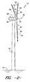
FIG. 2 illustrates a perspective view of one embodiment of a wind turbine; -
FIG. 3 illustrates a simplified, perspective view of the interior of the nacelle of the wind turbine shown inFIG. 2 ; -
FIG. 4 illustrates a schematic view of one embodiment of suitable components that may be included within a turbine controller of the wind turbine shown inFIG. 2 ; -
FIG. 5 illustrates a flow diagram of one embodiment of a method for controlling a wind turbine in accordance with aspects of the present subject matter; -
FIG. 6 illustrates an example graph charting both power output of a wind turbine (y-axis, left) as a function of time (x-axis) and component life of one or more wind turbine components (y-axis, right) as the wind turbine is operated over time along a predetermined rating curve in accordance with aspect of the present subject matter; -
FIG. 7 illustrates a graph showing example results of various loading analyses (e.g., LA#1-#5) performed on a wind turbine in order to determine its loading-based maximum power output in accordance with aspects of the present subject matter; -
FIG. 8 illustrates another example graph charting both power output of a wind turbine (y-axis, left) as a function of time time (x-axis) and component life of one or more wind turbine components (y-axis, right) as the wind turbine is operated over time along a different predetermined rating curve in accordance with aspect of the present subject matter; -
FIG. 9 illustrates a graph providing example loading bands representative of different loading conditions occurring for a wind turbine at different combinations of operating conditions; and -
FIG. 10 illustrates graph showing a portion of the predetermined rating curve shown inFIG. 6 , particularly illustrating adjustments that can be made when de-rating the wind turbine to account for the actual operating conditions of the turbine. - Reference now will be made in detail to embodiments of the invention, one or more examples of which are illustrated in the drawings. Each example is provided by way of explanation of the invention, not limitation of the invention. In fact, it will be apparent to those skilled in the art that various modifications and variations can be made in the present invention without departing from the scope or spirit of the invention. For instance, features illustrated or described as part of one embodiment can be used with another embodiment to yield a still further embodiment. Thus, it is intended that the present invention covers such modifications and variations as come within the scope of the appended claims and their equivalents.
- In general, the present subject matter is directed to a system and method for controlling a wind turbine. Specifically, the disclosed system and method provide for a wind turbine to be operated at an initial power output that exceeds its rated power output for an early portion of the turbine's operating life. As the wind turbine continues to be operated over time, the power output may be decreased from the initial power output in order to maintain the actual operating life of the wind turbine at or above its anticipated operating life. For instance, the wind turbine may be operated at a heightened power output (i.e., above its rated power output) over a first portion of the turbine's operating life in order to increase its power output and at a reduced power output (i.e., below its rated power output) for a second portion of the turbine's operating life in order to maintain the actual operating life of the wind turbine substantially equal to or greater than its anticipated operating life. As a result of this early load bias, the net present value of the wind turbine may be increased significantly early in its life without decreasing its overall operating life.
- Referring now to
FIG. 2 , a perspective view of one embodiment of awind turbine 10 is illustrated in accordance with aspects of the present subject matter. As shown, thewind turbine 10 generally includes atower 12 extending from asupport surface 14, anacelle 16 mounted on thetower 12, and arotor 18 coupled to thenacelle 16. Therotor 18 includes arotatable hub 20 and at least onerotor blade 22 coupled to and extending outwardly from thehub 20. For example, in the illustrated embodiment, therotor 18 includes threerotor blades 22. However, in an alternative embodiment, therotor 18 may include more or less than threerotor blades 22. Eachrotor blade 22 may be spaced about thehub 20 to facilitate rotating therotor 18 to enable kinetic energy to be transferred from the wind into usable mechanical energy, and subsequently, electrical energy. For instance, thehub 20 may be rotatably coupled to an electric generator 24 (FIG. 3 ) positioned within thenacelle 16 to permit electrical energy to be produced. - The
wind turbine 10 may also include a turbine control system orturbine controller 26 centralized within the nacelle 16 (or disposed at any other suitable location within and/or relative to the wind turbine 10). In general, theturbine controller 26 may comprise a computer or other suitable processing unit. Thus, in several embodiments, theturbine controller 26 may include suitable computer-readable instructions that, when implemented, configure thecontroller 26 to perform various different functions, such as receiving, transmitting and/or executing wind turbine control signals. As such, theturbine controller 26 may generally be configured to control the various operating modes (e.g., start-up or shut-down sequences) and/or components of thewind turbine 10. For example, thecontroller 26 may be configured to adjust the blade pitch or pitch angle of each rotor blade 22 (i.e., an angle that determines a perspective of theblade 22 with respect to the direction of the wind) about itspitch axis 28 in order to control the rotational speed of therotor blade 22 and/or the power output generated by thewind turbine 10. For instance, theturbine controller 26 may control the pitch angle of therotor blades 22, either individually or simultaneously, by transmitting suitable control signals to one or more pitch drives or pitch adjustment mechanisms 32 (FIG. 3 ) of thewind turbine 10. - Referring now to
FIG. 3 , a simplified, internal view of one embodiment of thenacelle 16 of thewind turbine 10 shown inFIG. 2 is illustrated. As shown, agenerator 24 may be disposed within thenacelle 16. In general, thegenerator 24 may be coupled to therotor 18 for producing electrical power from the rotational energy generated by therotor 18. For example, as shown in the illustrated embodiment, therotor 18 may include arotor shaft 38 coupled to thehub 20 for rotation therewith. Therotor shaft 38 may, in turn, be rotatably coupled to agenerator shaft 40 of thegenerator 24 through agearbox 42. As is generally understood, therotor shaft 38 may provide a low speed, high torque input to thegearbox 42 in response to rotation of therotor blades 22 and thehub 20. Thegearbox 42 may then be configured to convert the low speed, high torque input to a high speed, low torque output to drive thegenerator shaft 40 and, thus, thegenerator 24. - Additionally, as indicated above, the
controller 26 may also be located within the nacelle 16 (e.g., within a control box or panel). However, in other embodiments, thecontroller 26 may be located within any other component of thewind turbine 10 or at a location outside the wind turbine (e.g., when thecontroller 26 is configured as a farm controller for controlling a plurality of wind turbines). As is generally understood, thecontroller 26 may be communicatively coupled to any number of the components of thewind turbine 10 in order to control the operation of such components. For example, as indicated above, thecontroller 26 may be communicatively coupled to each pitch adjustment mechanism 32 of the wind turbine 10 (one for each rotor blade 22) via apitch controller 30 to facilitate rotation of eachrotor blade 22 about itspitch axis 28. - In general, each pitch adjustment mechanism 32 may include any suitable components and may have any suitable configuration that allows the pitch adjustment mechanism 32 to function as described herein. For example, in several embodiments, each pitch adjustment mechanism 32 may include a pitch drive motor 44 (e.g., any suitable electric motor), a
pitch drive gearbox 46, and apitch drive pinion 48. In such embodiments, thepitch drive motor 44 may be coupled to thepitch drive gearbox 46 so that thepitch drive motor 44 imparts mechanical force to thepitch drive gearbox 46. Similarly, thepitch drive gearbox 46 may be coupled to thepitch drive pinion 48 for rotation therewith. Thepitch drive pinion 48 may, in turn, be in rotational engagement with a pitch bearing 50 coupled between thehub 20 and acorresponding rotor blade 22 such that rotation of thepitch drive pinion 48 causes rotation of thepitch bearing 50. Thus, in such embodiments, rotation of thepitch drive motor 44 drives thepitch drive gearbox 46 and thepitch drive pinion 48, thereby rotating the pitch bearing 50 and therotor blade 22 about thepitch axis 28. In alternative embodiments, it should be appreciated that each pitch adjustment mechanism 32 may have any other suitable configuration that facilitates rotation of arotor blade 22 about itspitch axis 28. - In addition, the
wind turbine 10 may also include one or more sensors for monitoring various operating conditions of thewind turbine 10. For example, in several embodiments, thewind turbine 10 may include one ormore shaft sensors 60 configured to monitor one or more shaft-related operating conditions of thewind turbine 10, such as the loads acting on the rotor shaft 38 (e.g., thrust, bending and/or torque loads), the deflection of the rotor shaft 38 (e.g., including shaft bending), the rotational speed of therotor shaft 38 and/or the like. The wind turbine may also include one or more blades sensors 62 (FIGS. 2 and3 ) configured to monitor one or more blade-related operating conditions of thewind turbine 10, such as the loads acting on the blades 22 (e.g., bending loads), the deflection of the blades 22 (e.g., including blade bending, twisting and/or the like), the vibration of theblades 22, the noise generated by theblades 22, the pitch angle of theblades 22, the rotational speed of theblades 22 and/or the like. Additionally, thewind turbine 10 may include one ormore generator sensors 64 configured to monitor one or more generator-related operating conditions of thewind turbine 10, such as the power output of thegenerator 24, the rotational speed of thegenerator 24, the generator torque and/or the like. - Moreover, the
wind turbine 10 may also include various other sensors for monitoring numerous other turbine operating conditions. For example, as shown inFIG. 3 , thewind turbine 10 may include one ormore tower sensors 66 for monitoring various tower-related operating conditions, such as the loads acting thetower 12, the deflection of the tower 12 (e.g., tower bending and/or twisting), tower vibrations and/or the like. In addition, thewind turbine 10 may include one ormore wind sensors 68 for monitoring one or more wind conditions of thewind turbine 10, such as the wind speed, the wind direction, the turbulence or turbulence intensity of the wind and/or the like. Similarly, thewind turbine 10 may include one ormore hub sensors 70 for monitoring various hub-related operating conditions (e.g., the loads transmitted through thehub 20, hub vibrations and/or the like), one ormore nacelle sensors 72 for monitoring one or more nacelle-related operating conditions (e.g., the loads transmitted through thenacelle 16, nacelle vibrations and/or the like) and/or one ormore gearbox sensors 74 for monitoring one or more gearbox-related operating conditions (e.g., gearbox torque, gearbox loading, rotational speeds within the gearbox and/or the like). Of course, thewind turbine 10 may further include various other suitable sensors for monitoring any other suitable operating conditions of thewind turbine 10. It should be appreciated that the various sensors described herein may correspond to pre-existing sensors of awind turbine 10 and/or sensors that have been specifically installed within thewind turbine 10 to allow one or more operating conditions to be monitored. - It should also be appreciated that, as used herein, the term "monitor" and variations thereof indicates that the various sensors of the
wind turbine 10 may be configured to provide a direct measurement of the operating conditions being monitored or an indirect measurement of such operating conditions. Thus, the sensors may, for example, be used to generate signals relating to the operating condition being monitored, which can then be utilized by thecontroller 26 to determine the actual operating condition. For instance, measurement signals provided by blade sensor(s) 62 that measure the deflection of eachrotor blade 22 may be used by thecontroller 26 to determine one or more blade-related operating conditions (e.g., blade loading) and/or one or more other operating conditions of the wind turbine 10 (e.g., turbulence intensity of the wind). - Referring now to
FIG. 4 , a block diagram of one embodiment of suitable components that may be included within thecontroller 26 is illustrated in accordance with aspects of the present subject matter. As shown, thecontroller 26 may include one or more processor(s) 76 and associated memory device(s) 78 configured to perform a variety of computer-implemented functions (e.g., performing the methods, steps, calculations and the like disclosed herein). As used herein, the term "processor" refers not only to integrated circuits referred to in the art as being included in a computer, but also refers to a controller, a microcontroller, a microcomputer, a programmable logic controller (PLC), an application specific integrated circuit, and other programmable circuits. Additionally, the memory device(s) 78 may generally comprise memory element(s) including, but are not limited to, computer readable medium (e.g., random access memory (RAM)), computer readable non-volatile medium (e.g., a flash memory), a floppy disk, a compact disc-read only memory (CD-ROM), a magneto-optical disk (MOD), a digital versatile disc (DVD) and/or other suitable memory elements. Such memory device(s) 78 may generally be configured to store suitable computer-readable instructions that, when implemented by the processor(s) 76, configure thecontroller 26 to perform various functions including, but not limited to, implementing the methods disclosed herein. - Additionally, the
controller 26 may also include acommunications module 80 to facilitate communications between the controller(s) 26 and the various components of thewind turbine 10. For instance, thecommunications module 80 may include a sensor interface 82 (e.g., one or more analog-to-digital converters) to permit the signals transmitted by the sensor(s) 60, 62, 64, 66, 68, 70, 72, 74 to be converted into signals that can be understood and processed by theprocessors 76. - Referring now to
FIG. 5 , a flow diagram of one embodiment of amethod 200 for controlling a wind turbine is illustrated in accordance with aspects of the present subject matter. As indicated above, the disclosedmethod 200 may be utilized to achieve increased power outputs early in a wind turbine's operating life without substantially reducing the overall operating life of theturbine 10. Specifically, during an initial operating period of the turbine's life, thewind turbine 10 may be uprated so that it is operated at a power output greater than its rated power. As a result, the various components of thewind turbine 10 may be subjected to increased loading during this initial operating period, which may lead to increased component wear/damage/degradation. For awind turbine 10 having an anticipated operating life that is limited by the anticipated component life of one or more of its life-limiting components, continued operation at such heightened power outputs can significantly reduce the turbine's actual operating life. Thus, in accordance with aspects of the present subject matter, the power output of thewind turbine 10 may be reduced over time from the heightened power output levels to output levels below the rated power output such that the actual operating life of the wind turbine is maintained substantially equal to or greater than its anticipated operating life. - To illustrate several principles of the present subject matter, the
method 200 shown inFIG. 5 will generally be described with reference toFIG. 6 , which provides a comparative example to the conventional method for wind turbine operation described above with reference toFIG. 1 . Specifically, unlike the example inFIG. 1 in which thewind turbine 10 is operated continuously at its rated power along a constant rating curve (shown inFIG. 6 as dashed line 106), thewind turbine 10 is configured to be operated according to apredetermined rating curve 306 along which the power output is at increased levels (i.e., above the turbine's rated power) during an initial,first time period 310 and then transitions to reduced power outputs (i.e., below the turbine's rated power) during a subsequentsecond time period 312. As a result, the power production of thewind turbine 10 may be significantly increased during thefirst time period 310. However, such increased power ratings may also result in in a substantial increase in the rate at which the components of thewind turbine 10 are worn down, damaged or otherwise degraded. For example, as shown inFIG. 6 , the remaining component life for any of the life-limiting components of the wind turbine 10 (indicated by component life curve 304) is significantly reduced during thefirst time period 310. Specifically, unlike the example shown inFIG. 1 in which the remaining component life at themidpoint 108 of the turbine's anticipated operating life was equal to about 50%, the remaining component life atsuch midpoint 108 is well below 50%. Thus, to prevent a reduction in the overall operating life of thewind turbine 10, the power rating may be reduced below the rated power output during thesecond time period 312 to slow component degradation. For instance, as shown inFIG. 5 , the power rating may be reduced such that thecomponent life curve 304 flattens out and extends to a point at and/or beyond theline 102 defining the end of the turbine'santicipated operating life 100, thereby ensuring that the actual operating life of theturbine 10 is substantially equally to or greater than itsanticipated operating life 100. - It should be appreciated that, as used herein, the actual operating life a
wind turbine 10 is "substantially equal to" its anticipated operating life if the actual operating life falls within 5% of the turbine's anticipated operating life. - As shown in
FIG. 5 , at (202), themethod 200 includes installing awind turbine 10 at a given wind turbine site. In several embodiments, thewind turbine 10 being installed may correspond to the only wind turbine located at such site or may correspond to one of many wind turbines forming part a wind turbine farm at the selected site. It should be appreciated that, whenmultiple wind turbines 10 are installed at a given site, eachwind turbine 10 may be individually controlled (via each turbine's controller 26) using the methods disclosed herein. Alternatively, thewind turbines 10 may be controlled together via a farm controller. - Additionally, at (204), the
method 200 includes operating thewind turbine 10 at an initial power output that is greater than its rated power output. Specifically, as indicated above, once thewind turbine 10 is installed at the site, thewind turbine 10 may be controlled during an initial operational period so that the turbine's power output is above its rated power output in order to increase the turbine's output over an early portion of its life. For example, as shown inFIG. 6 , the initial power output of the wind turbine (indicated at point 320) may be well above the turbine's rated power. - It should be appreciated that the
wind turbine 10 may be controlled in any suitable manner that allows such a heightened initial power output to be achieved. For example, as is generally understood, the pitch angle of therotor blades 22 of awind turbine 10 are typically pitched (e.g., using the pitch adjustment mechanisms 32) towards feather as wind speeds reach and exceed the turbine's rated wind speed in order to maintain thewind turbine 10 operating at its rated power output. Thus, in several embodiments, such pitching of therotor blades 22 may be eliminated and/or delayed to allow the heightened initial power output to be achieved. - It should also be appreciated that the initial power output may generally correspond to any suitable power output that is greater than the wind turbine's rated power output.
- However, in several embodiments, the initial power output may be selected based on a maximum power output determined for the
wind turbine 10. Specifically, a loading analysis may be performed on thewind turbine 10 to determine its maximum power output based on the load margins for the turbine's components. For example, when operating at its rated power, a substantial load margin may exist between the actual loading on the wind turbine's components and the design envelope or loading threshold for each component (i.e., the point at which a given component will actually fail due to excessive loading). Thus, by analyzing the load margins for a givenwind turbine 10, the load-based maximum power output for thewind turbine 10 may be determined. This maximum power output may then be utilized as the initial power output for thewind turbine 10. - In several embodiments, the loading analysis may be performed using a computer-generated model. For example, a three-dimensional model (e.g., a finite element model) of the
wind turbine 10 may be created using suitable modeling software. In doing so, the various design and/or mechanical parameters for each wind turbine component (e.g., geometry/shape, dimensions and material properties, such as poison's ratio, Young's modulus and density, etc.) may be input into the model. Thereafter, using suitable load analysis software (e.g., any suitable commercially available finite element analysis software), the operation of thewind turbine 10 may be modeled based on the turbine's known and/or expected operating conditions. - For instance, in several embodiments, site-specific wind conditions, such as an average wind speed at the site (e.g., an annual average wind speed or a twenty year average wind speed), an average wind speed distribution at the site (i.e., the distribution or profile of the wind speed over an extended period of time) and/or any other suitable site-specific operating condition(s) (e.g., wind gusts and/or turbulence intensity at the site), may be used as loading inputs to accurately model the operation of the
wind turbine 10 based on its known and/or expected operating conditions. The resulting component loads may then be analyzed based on the loading threshold for each wind turbine component to identify the maximum rotor speed and torque setting that thewind turbine 10 may be operated without a component failure, which may then be used to determine the maximum power output of thewind turbine 10. - For instance,
FIG. 7 illustrates an example data chart showing the results of various loading analyses (e.g., LA #1-#5) performed on a 1.5 MW wind turbine, with several of the wind turbine components being charted along the x-axis and the % margin to loading threshold being charted along the y-axis. As shown, at the rated power of 1.5 MW, the loading analysis indicated that a substantial load margin existed for each of the wind turbine components. However, as the rotor speed and/or torque settings of the wind turbine were increased to allow for increased power outputs, the component loads also increased, thereby reducing the load margins for each component. For instance, as shown inFIG. 7 , when operating at a power output of 1.8 MW, the load margin for the pitch bearing transitions from positive to negative, thereby indicating a high likelihood that the pitch bearing would fail due to excessive loading. Thus, it may be determined that, based on the known and/or expected operating conditions of the particular wind turbine being analyzed, the maximum power output for such wind turbine is below 1.8 MW, such as at 1.7 MW or 1.75 MW. This maximum power output may then, in several embodiments, be utilized as the initial power output for thewind turbine 10. - It should be appreciated that, although a wind turbine installed within a wind farm may have the exact same design specifications as other wind turbines with the farm, the maximum power output for each wind turbine may vary due to varying operating conditions. For example, wind turbines located on the left side of a field may be subjected to lower average wind speeds and/or lower wind distributions than wind turbines located on the right side of the field (e.g., due to terrain differences, such as hills, etc.). As a result, the loading analysis may indicate that the wind turbines on the left side of the field have a higher maximum power output than the wind turbines on the right side of the field due to the lower loads acting on such wind turbines. Similarly, wind turbines located downstream of other wind turbines may be subject to vastly different operating conditions than the upstream wind turbines and, thus, the maximum power outputs may differ between the upstream and downstream wind turbines.
- It should also be appreciated that, in alternative embodiments, the initial power output utilized when performing
method element 204 may correspond to any other suitable power output that is greater than the rated power output for thewind turbine 10 being controlled, such as any power output between the maximum power output forsuch wind turbine 10 and its rated power output. - Referring back to
FIG. 5 , at (206), themethod 200 includes decreasing the power output of thewind turbine 10 over time from the initial power output to a final power output that is less than the rated power output for the turbine. Specifically, as indicated above, the power output may be decreased over time so that an actual operating life of thewind turbine 10 is substantially equal to or greater than its anticipated operational life. For instance, as shown inFIG. 6 , in several embodiments, the power output may be decreased over time between theinitial power output 320 and the final power output (indicated by point 322) according to apredetermined rating curve 306. In general, thisrating curve 306 may be selected such that thecomponent life curve 304 for any life-limiting components of thewind turbine 10 extends across a time period that is substantially equal to or greater than the anticipated operatinglife 100 of thewind turbine 10. Thus, if the turbine's anticipated operating life is 20 years, thewind turbine 10 may be de-rated from the initial,heighted power output 320 in a manner that permits the component life of any of its life-limiting components to extend for at least about 20 years. - It should be appreciated that the predetermined rating curve may generally correspond to any suitable operating curve that allows for the
wind turbine 10 to be operated across its entire anticipated operating life. For instance, as shown inFIG. 6 , thepredetermined rating curve 306 defines a straight line between the initial andfinal power outputs turbine 10 is reduced linearly over time. However, in other embodiments, thepredetermined rating curve 306 may be selected so as to define a curved line between the initial andfinal power outputs - It should also be appreciated that, in several embodiments, the
predetermined rating curve 306 may be selected such that the power output of thewind turbine 10 is continuously reduced between the initial and final power outputs (e.g. as shown inFIG. 6 ). However, in other embodiments, the power output of thewind turbine 10 need not be continuously reduced over time. For instance, as shown in example ofFIG. 8 , the power output is maintained at its initial, heightenedpower output 320 for an extended period oftime 350 prior to being reduced over ade-rating period 352. The power output is then maintained at thefinal power output 322 over another extended period oftime 354. In such an embodiment, by carefully selecting thetime periods final power outputs de-rating period 352, the actual operating life of thewind turbine 10 may be maintained substantially equal to or greater than its anticipated operating life 100 (e.g., as indicated by thecomponent life curve 304 ofFIG. 8 ). - Additionally, it should be appreciated that, in several embodiments, the
wind turbine 10 may be operated along itspredetermined rating curve 306 without reference to any of its actual operating conditions. Thus, if the time reference for therating curve 306 is based on the operating time of the wind turbine 10 (i.e., the amount of time the turbine is actually operated), thecontroller 26 may simply be configured to control theturbine 10 so that its power output is maintained along the rating curve as the turbine is operated over time. Similarly, if the time reference for therating curve 306 is based on calendar time, thecontroller 26 may be configured to control theturbine 10 so that its power output is maintained along the rating curve as time passes. In such an embodiment, if thewind turbine 10 has been down for any period of time, upon start-up of theturbine 10, thecontroller 26 may be configured to shift the current operating point along therating curve 306 to the right to account for such downtime. - Alternatively, the
controller 26 may be configured to adjust the operating point along thepredetermined rating curve 306 based on one or more operating conditions of thewind turbine 10. Specifically, in several embodiments, it may be assumed that awind turbine 10 is subjected to the average loading conditions expected or observed at its site when initially determining the reduction in component life that occurs while theturbine 10 is operating at a given power rating for any specific period of time. Thus, if it is determined that thewind turbine 10 is instead operating in lower loading conditions over the specific period of time, the operating point along therating curve 306 may need to be adjusted in one direction to account for the reduced component wear/damage/degradation occurring during such time period. Similarly, if it is determined that thewind turbine 10 is instead operating in higher loading conditions over the specific period of time, the operating point along therating curve 306 may need to be adjusted in the other direction to account for the increased component wear/damage/degradation occurring during such time period. - Thus, referring back to
FIG. 5 , at 208, themethod 200 may, in several embodiments, include monitoring one or more operating conditions of thewind turbine 10. For example, as indicated above, thewind turbine 10 may include a plurality of sensors (e.g.,sensors wind turbine 10. Measurement signals provided by the sensors may then be transmitted to thecontroller 26 to allow thecontroller 26 to monitor such operating condition(s). - Additionally, at 210, the
method 200 includes determining a time adjustment for thepredetermined rating curve 306 based on the monitored operating condition(s). Specifically, in several embodiments, thecontroller 26 may be configured to determine the effect of the current operating conditions for thewind turbine 10 on the component life of any of the turbine's life-limiting components. For example, in one embodiment, thecontroller 26 may be configured to estimate a damage factor for such component(s) based on the current operating conditions. This damage factor may then be correlated to a time adjustment for adjusting the operational point of thewind turbine 10 along thepredetermined rating curve 306. - For example,
FIG. 9 illustrates a graph providing example data that may be used by thecontroller 26 to correlate the current operating conditions of awind turbine 10 to a corresponding damage factor that is representative of the difference between the expected change in component life over time (e.g., at average operating conditions) and the actual change in component life over time based on such current operating conditions. As shown inFIG. 9 , the example data is provided as a function of wind speed (x-axis) and turbulence intensity (y-axis). However, in other embodiments, any other suitable operating conditions may be used as a basis for determining the disclosed damage factor. - As shown in
FIG. 9 , the graph includes a plurality of loadingbands average loading band 400, first and second low-loadingbands high loading bands - In several embodiments, the
average loading band 400 may be selected so that it extends across various combinations of wind speed and turbulence intensity at which thewind turbine 10 is generally experiencing average or normal loading conditions. Additionally, the low-loadingbands wind turbine 10 is operating at lower loading conditions as compared to those of theaverage loading band 400. Thus, as the wind speed and/or wind turbulence is reduced from those contained within theaverage loading band 400, the operation of thewind turbine 10 may transition into the first low-loading band 402 and, with further reductions in the wind speed and/or wind turbulence, into the second low-loading band 404. Similarly, the high-loadingbands wind turbine 10 is operating at higher loading conditions as compared to those of theaverage loading band 400. Thus, as the wind speed and/or wind turbulence is increased from those contained within theaverage loading band 400, the operation of thewind turbine 10 may transition into the first high-loading band 406 and, with further increases in the wind speed and/or wind turbulence, into the second high-loading band 408. - It should be appreciated that the
various loading bands FIG. 9 are simply provided as examples of loading bands that may be developed based on changes in turbine loading conditions as a function of wind speed and wind turbulence. One of ordinary skill in the art should readily appreciate that similar loading bands may be developed for any other suitable combination of operating conditions by modeling thewind turbine 10 based on such changing conditions or by performing any other suitable type of analysis. - Additionally, in several embodiments, each
loading band wind turbine 10 while theturbine 10 is operating at a specific set of operating conditions. Thus, the damage factor may be larger for loading conditions that are above the normal or expected loading conditions and smaller for loading conditions that are below the normal or expected loading conditions. For example, in a particular embodiment of the present subject matter, theaverage loading band 400 may be assigned a specific damage factor, such as a damage factor of 1. Additionally, the low-loadingbands average loading band 400, such as a damage factor of 0.1 for the first low-loading band 402 and a damage factor of 0.01 for the second low-loading band 404. Similarly, the high-loadingbands average loading band 400, such as a damage factor of 10 for the first high-loading band 406 and a damage factor of 100 for the second high-loading band 408. - Once determined, the damage factor may then be utilized to calculate a time adjustment for the
predetermined rating curve 306. Specifically, in several embodiments, the damage factor may be multiplied by the amount of time over which thewind turbine 10 was operating within theloading band FIG. 9 , if thewind turbine 10 is operated withinaverage loading band 400 over a period of ten minutes, the time adjustment may be equal to 10 minutes (i.e., 10 minutes multiplied by a damage factor of 1). However, if thewind turbine 10 is operated within the first low-loading band 402 over a period of ten minutes, the time adjustment may be equal to 1 minute (i.e., 10 minutes multiplied by a damage factor of 0.1). Similarly, if thewind turbine 10 is operated within the second high-loading band 408 over a period of ten minutes, the time adjustment may be equal to 1000 minutes (i.e., 10 minutes multiplied by a damage factor of 100). - Referring back to
FIG. 5 , at 212, themethod 200 includes selecting an operational point along thepredetermined rating curve 306 for thewind turbine 10 based on the calculated time adjustment. For example,FIG. 10 illustrates a portion of thepredetermined rating curve 306 shown inFIG. 6 . As shown inFIG. 10 , if thecontroller 26 is simply configured to follow therating curve 306 over time without accounting for time adjustments, thecontroller 26 may be configured to de-rate thewind turbine 10 from afirst power output 500 to asecond power output 502 over a given time period X. Similarly, using the example damage factor values shown inFIG. 9 , thecontroller 26 may also be configured to de-rate thewind turbine 10 from thefirst power output 500 to the second power output 502over the time period X assuming theturbine 10 is operated within theaverage loading band 400 for the entire time period X (due to the damage factor being equal to 1). However, when thewind turbine 10 is operating in low-loading or high-loading conditions, the calculated time adjustment may be used to adjust the operational point to a different location along thepredetermined rating curve 306, thereby adjusting the amount that thewind turbine 10 is de-rated in order to account for such low/high loading conditions. - Specifically, if the
wind turbine 10 is operating within one of the low-loadingbands wind turbine 10 is de-rated across the time period may be reduced to account for the decreased component loading occurring during such time period. For instance, using the example damage factor values shown inFIG. 9 , if thewind turbine 10 is operating within the first low-loading band 402 over time period X, thecontroller 26 may be configured to de-rate thewind turbine 10 from thefirst power output 500 to a power output (indicated by point 504) corresponding to the power output along thepredetermined rating curve 306 that is offset from thefirst power output 500 by a time adjustment of X/10 (i.e., due to the damage factor of 0.1). Similarly, if thewind turbine 10 is operated within one of the high-loadingbands wind turbine 10 is de-rated across the time period may be increased significantly to account for the increased component loading occurring during such time period. For instance, again using the example damage factor values shown inFIG. 9 , if thewind turbine 10 is operated within the first high-loading band 406 over time period X, thecontroller 26 may be configured to de-rate thewind turbine 10 from thefirst power output 500 to a power output (indicated by point 506) corresponding to the power output along thepredetermined rating curve 306 that is offset from thefirst power output 500 by a time adjustment of 10*X (i.e., due to the damage factor of 10). Accordingly, by using such time adjustments, the operational point of thewind turbine 10 may be accurately adjusted along thepredetermined rating curve 306 to account for the actual reduction in component life occurring to a given life-limiting component based on the turbine's actual operating conditions, thereby allowing thecontroller 26 to enhance operational efficiency of thewind turbine 10 while still maintaining the actual operating life of theturbine 10 substantially equal to or greater than its anticipated operating life. - It should be appreciated that, in alternative embodiments, the time adjustment for the
predetermined rating curve 306 may be determined using any other suitable methodology (e.g., by using a different base factor to calculate the time adjustment or by simply calculating the time adjustment directly based on one or more operating conditions of the wind turbine 10). In addition, it should be appreciated that the time adjustment may also be applied to adjust the operational point along thepredetermined rating curve 206 in any other suitable manner that allows thecontroller 26 to at least partially account for the actual reduction in component life occurring during operation of thewind turbine 10. - Additionally, as shown in
FIG. 5 , while thecontroller 26 continues to adjust the operational point along thepredetermined rating curve 306 based on the calculated time adjustments, the power output may still be decreased over time from the initial power output to the final power output (as shown at 206). - This written description uses examples to disclose the invention, including the preferred mode, and also to enable any person skilled in the art to practice the invention, including making and using any devices or systems and performing any incorporated methods. The patentable scope of the invention is defined by the claims, and may include other examples that occur to those skilled in the art. Such other examples are intended to be within the scope of the claims if they include structural elements that do not differ from the literal language of the claims, or if they include equivalent structural elements with insubstantial differences from the literal languages of the claims.
- Various aspects and embodiments of the present invention are defined by the following numbered clauses:
- 1. A method for controlling a wind turbine having an anticipated operational life at a rated power output, the method comprising:
- operating the wind turbine at an initial power output that is greater than the rated power output for the wind turbine; and
- decreasing a power output of the wind turbine over time in order to maintain an actual operating life of the wind turbine substantially equal to or greater than the anticipated operational life, wherein a final power output of the wind turbine at an end of the anticipated operating life is less than the rated power output.
- 2. The method of
clause 1, further comprising performing a loading analysis on the wind turbine to determine a maximum power output for the wind turbine. - 3. The method of any preceding clause, further comprising setting the initial power output of the wind turbine as the maximum power output.
- 4. The method of any preceding clause, wherein decreasing the power output of the wind turbine over time comprises decreasing the power output over time along a predetermined rating curve between the initial power output and the final power output.
- 5. The method of any preceding clause, wherein the predetermined rating curve defines a straight line between the initial power output and the final power output.
- 6. The method of any preceding clause, further comprising:
- monitoring at least one operating condition of the wind turbine; and
- determining a time adjustment for the predetermined rating curve based on the at least one operating condition.
- 7. The method of any preceding clause, further comprising selecting an operational point for the wind turbine along the predetermined rating curve based on the time adjustment.
- 8. The method of any preceding clause, further comprising determining a damage factor for at least one life-limiting component of the wind turbine based on the at least one operating condition, wherein the time adjustment is determined based on the damage factor.
- 9. The method of any preceding clause, wherein the damage factor varies depending on a loading condition of the wind turbine.
- 10. The method of any preceding clause, wherein the anticipated operating life of the wind turbine is limited based on an anticipated component life of at least one life-limiting component of the wind turbine.
- 11. A system, comprising:
- a wind turbine having an anticipated operating life at a rated power output;
- a controller configured to control the operation of the wind turbine, the controller being configured to operate the wind turbine at an initial power output that is greater than the rated power output, the controller being further configured to decrease a power output of the wind turbine over time in order to maintain an actual operating life of the wind turbine substantially equal to or greater than the anticipated operational life, wherein a final power output of the wind turbine at an end of the anticipated operating life is less than the rated power output.
- 12. The system of any preceding clause, wherein the controller is further configured to perform a loading analysis on the wind turbine to determine a maximum power output for the wind turbine.
- 13. The system of any preceding clause, wherein the controller is configured to set the initial power output of the wind turbine as the maximum power output.
- 14. The system of any preceding clause, wherein the controller is configured to decrease the power output over time along a predetermined rating curve between the initial power output and the final power output.
- 15. The system of any preceding clause, wherein the power output is continuously decreased along the predetermined rating curve between the initial power output and the final power output.
- 16. The system of any preceding clause, wherein the controller is further configured to monitor at least one operating condition of the wind turbine and determine a time adjustment for the predetermined rating curve based on the at least one operating condition.
- 17. The system of any preceding clause, wherein the controller is further configured to select an operational point for the wind turbine along the predetermined rating curve based on the time adjustment.
- 18. The system of any preceding clause, wherein the controller is further configured to determine a damage factor for at least one life-limiting component of the wind turbine based on the at least one operating condition and wherein the controlled is configured to determine the time adjustment based on the damage factor.
- 19. The system of any preceding clause, wherein the damage factor varies depending on a loading condition of the wind turbine.
- 20. The system of any preceding clause, wherein the anticipated operating life of the wind turbine is limited based on an anticipated component life of at least one life-limiting component of the wind turbine.
Claims (15)
- A method (200) for controlling a wind turbine (10) having an anticipated operational life at a rated power output, the method comprising:operating the wind turbine at an initial power output (320) that is greater than the rated power output for the wind turbine (10); anddecreasing a power output of the wind turbine (10) over time in order to maintain an actual operating life of the wind turbine (10) substantially equal to or greater than the anticipated operational life, wherein a final power output (322) of the wind turbine (10) at an end of the anticipated operating life is less than the rated power output.
- The method (200) of claim 1, further comprising performing a loading analysis on the wind turbine (10) to determine a maximum power output for the wind turbine (10).
- The method (200) of claim 2, further comprising setting the initial power output of the wind turbine (10) as the maximum power output.
- The method (200) of any preceding claim, wherein decreasing the power output of the wind turbine (10) over time comprises decreasing the power output over time along a predetermined rating curve (306) between the initial power output and the final power output.
- The method (200) of claim 4, wherein the predetermined rating curve (306) defines a straight line between the initial power output and the final power output.
- The method (200) of claim 4 or claim 5, further comprising:monitoring at least one operating condition of the wind turbine (10); anddetermining a time adjustment for the predetermined rating curve (306) based on the at least one operating condition.
- The method (200) of claim 6, further comprising selecting an operational point for the wind turbine (10) along the predetermined rating curve based on the time adjustment.
- The method (200) of claim 6 or claim 7, further comprising determining a damage factor for at least one life-limiting component of the wind turbine (10) based on the at least one operating condition, wherein the time adjustment is determined based on the damage factor.
- The method (200) of claim 8, wherein the damage factor varies depending on a loading condition of the wind turbine (10).
- The method (200) of any preceding claim, wherein the anticipated operating life of the wind turbine (10) is limited based on an anticipated component life of at least one life-limiting component of the wind turbine.
- A system, comprising:a wind turbine (10) having an anticipated operating life at a rated power output;a controller (26) configured to control the operation of the wind turbine (10), the controller (26) being configured to operate the wind turbine (10) at an initial power output (320) that is greater than the rated power output, the controller (26) being further configured to decrease a power output of the wind turbine (10) over time in order to maintain an actual operating life of the wind turbine (10) substantially equal to or greater than the anticipated operational life, wherein a final power output (322) of the wind turbine (10) at an end of the anticipated operating life is less than the rated power output.
- The system of claim 11, wherein the controller (26) is further configured to perform a loading analysis on the wind turbine (10) to determine a maximum power output for the wind turbine (10).
- The system of claim 12, wherein the controller (26) is configured to set the initial power output of the wind turbine (10) as the maximum power output.
- The system of any of claims 11 to 13, wherein the controller (26) is configured to decrease the power output over time along a predetermined rating curve between the initial power output and the final power output.
- The system of any of claims 11 to 14, wherein the anticipated operating life of the wind turbine (10) is limited based on an anticipated component life of at least one life-limiting component of the wind turbine (10).
Applications Claiming Priority (1)
| Application Number | Priority Date | Filing Date | Title |
|---|---|---|---|
| US14/068,356 US9835135B2 (en) | 2013-10-31 | 2013-10-31 | System and method for controlling a wind turbine |
Publications (2)
| Publication Number | Publication Date |
|---|---|
| EP2868918A1 true EP2868918A1 (en) | 2015-05-06 |
| EP2868918B1 EP2868918B1 (en) | 2018-12-12 |
Family
ID=51753153
Family Applications (1)
| Application Number | Title | Priority Date | Filing Date |
|---|---|---|---|
| EP14190166.0A Active EP2868918B1 (en) | 2013-10-31 | 2014-10-23 | System and method for controlling a wind turbine |
Country Status (5)
| Country | Link |
|---|---|
| US (1) | US9835135B2 (en) |
| EP (1) | EP2868918B1 (en) |
| CA (1) | CA2868659C (en) |
| DK (1) | DK2868918T3 (en) |
| ES (1) | ES2707923T3 (en) |
Cited By (3)
| Publication number | Priority date | Publication date | Assignee | Title |
|---|---|---|---|---|
| CN105240211A (en) * | 2015-11-10 | 2016-01-13 | 四川东方电气自动控制工程有限公司 | Variable-speed variable-pitch wind turbine generator optimized power curve control method |
| US10578080B2 (en) | 2015-06-30 | 2020-03-03 | Vestas Wind Systems A/S | Initialisation of wind turbine control functions |
| EP3792482A1 (en) * | 2019-09-16 | 2021-03-17 | Siemens Gamesa Renewable Energy A/S | Power boost for a wind turbine |
Families Citing this family (33)
| Publication number | Priority date | Publication date | Assignee | Title |
|---|---|---|---|---|
| EP3317523B1 (en) * | 2015-06-30 | 2020-09-23 | Vestas Wind Systems A/S | Methods and systems for generating wind turbine control schedules |
| WO2017000955A1 (en) * | 2015-06-30 | 2017-01-05 | Vestas Wind Systems A/S | Wind turbine control based on forecasts |
| ES2887575T3 (en) * | 2015-09-22 | 2021-12-23 | Vestas Wind Sys As | Power output changes by varying power output below rated speed and rotor speed below rated speed |
| EP3181897B1 (en) | 2015-12-18 | 2021-11-24 | Siemens Gamesa Renewable Energy A/S | Operating a wind turbine |
| CN105510038B (en) * | 2015-12-31 | 2018-07-27 | 北京金风科创风电设备有限公司 | Wind turbine generator fault monitoring method and device |
| JP6421134B2 (en) * | 2016-01-29 | 2018-11-07 | 三菱重工業株式会社 | Wind power generator and operation method thereof |
| US10125691B2 (en) | 2016-02-12 | 2018-11-13 | United Technologies Corporation | Bowed rotor start using a variable position starter valve |
| US10436064B2 (en) | 2016-02-12 | 2019-10-08 | United Technologies Corporation | Bowed rotor start response damping system |
| US10539079B2 (en) | 2016-02-12 | 2020-01-21 | United Technologies Corporation | Bowed rotor start mitigation in a gas turbine engine using aircraft-derived parameters |
| US10125636B2 (en) | 2016-02-12 | 2018-11-13 | United Technologies Corporation | Bowed rotor prevention system using waste heat |
| US10443507B2 (en) | 2016-02-12 | 2019-10-15 | United Technologies Corporation | Gas turbine engine bowed rotor avoidance system |
| US10443505B2 (en) | 2016-02-12 | 2019-10-15 | United Technologies Corporation | Bowed rotor start mitigation in a gas turbine engine |
| US10040577B2 (en) | 2016-02-12 | 2018-08-07 | United Technologies Corporation | Modified start sequence of a gas turbine engine |
| US10508601B2 (en) | 2016-02-12 | 2019-12-17 | United Technologies Corporation | Auxiliary drive bowed rotor prevention system for a gas turbine engine |
| US10174678B2 (en) | 2016-02-12 | 2019-01-08 | United Technologies Corporation | Bowed rotor start using direct temperature measurement |
| US9664070B1 (en) | 2016-02-12 | 2017-05-30 | United Technologies Corporation | Bowed rotor prevention system |
| US10508567B2 (en) | 2016-02-12 | 2019-12-17 | United Technologies Corporation | Auxiliary drive bowed rotor prevention system for a gas turbine engine through an engine accessory |
| US10598047B2 (en) | 2016-02-29 | 2020-03-24 | United Technologies Corporation | Low-power bowed rotor prevention system |
| US10787933B2 (en) | 2016-06-20 | 2020-09-29 | Raytheon Technologies Corporation | Low-power bowed rotor prevention and monitoring system |
| US20180003154A1 (en) * | 2016-06-30 | 2018-01-04 | General Electric Company | Methods and systems for feedforward control of wind turbines |
| US10358936B2 (en) | 2016-07-05 | 2019-07-23 | United Technologies Corporation | Bowed rotor sensor system |
| US10221774B2 (en) | 2016-07-21 | 2019-03-05 | United Technologies Corporation | Speed control during motoring of a gas turbine engine |
| US10618666B2 (en) | 2016-07-21 | 2020-04-14 | United Technologies Corporation | Pre-start motoring synchronization for multiple engines |
| EP3273016B1 (en) | 2016-07-21 | 2020-04-01 | United Technologies Corporation | Multi-engine coordination during gas turbine engine motoring |
| EP3273006B1 (en) | 2016-07-21 | 2019-07-03 | United Technologies Corporation | Alternating starter use during multi-engine motoring |
| US10384791B2 (en) | 2016-07-21 | 2019-08-20 | United Technologies Corporation | Cross engine coordination during gas turbine engine motoring |
| US10787968B2 (en) | 2016-09-30 | 2020-09-29 | Raytheon Technologies Corporation | Gas turbine engine motoring with starter air valve manual override |
| US10443543B2 (en) | 2016-11-04 | 2019-10-15 | United Technologies Corporation | High compressor build clearance reduction |
| EP3542055B1 (en) * | 2016-11-18 | 2021-09-29 | Vestas Offshore Wind A/S | Operating wind turbine above rating during low erosion conditions |
| US10823079B2 (en) | 2016-11-29 | 2020-11-03 | Raytheon Technologies Corporation | Metered orifice for motoring of a gas turbine engine |
| US10415544B2 (en) * | 2017-01-03 | 2019-09-17 | General Electric Company | System and method for determining torque on a wind turbine shaft |
| CN108869173B (en) | 2018-01-31 | 2019-08-16 | 北京金风科创风电设备有限公司 | Power control method and equipment for wind turbine generator |
| EP3867520B1 (en) * | 2018-10-18 | 2022-11-30 | Vestas Wind Systems A/S | Modifying control strategy for control of a wind turbine using load probability and design load limit |
Citations (5)
| Publication number | Priority date | Publication date | Assignee | Title |
|---|---|---|---|---|
| US6850821B2 (en) * | 2000-03-09 | 2005-02-01 | General Electric Company | Control system for a wind power plant |
| EP2302208A1 (en) * | 2009-09-23 | 2011-03-30 | Siemens Aktiengesellschaft | Dynamic adaptation of a set point for a fatigue life of a structural component of a power generating machine |
| WO2013044925A1 (en) * | 2011-09-30 | 2013-04-04 | Vestas Wind Systems A/S | Control of wind turbines |
| US20130214534A1 (en) * | 2012-02-21 | 2013-08-22 | Mitsubishi Heavy Industries, Ltd. | Method for operating wind farm and operation control system for wind farm |
| US20130320674A1 (en) * | 2012-05-30 | 2013-12-05 | Clipper Windpower, Llc | Net Present Value Optimized Wind Turbine Operation |
Family Cites Families (15)
| Publication number | Priority date | Publication date | Assignee | Title |
|---|---|---|---|---|
| US8649911B2 (en) | 2005-06-03 | 2014-02-11 | General Electric Company | System and method for operating a wind farm under high wind speed conditions |
| US7560823B2 (en) | 2006-06-30 | 2009-07-14 | General Electric Company | Wind energy system and method of operation thereof |
| US20090099702A1 (en) | 2007-10-16 | 2009-04-16 | General Electric Company | System and method for optimizing wake interaction between wind turbines |
| US8441138B2 (en) | 2009-05-07 | 2013-05-14 | Vestas Wind Systems A/S | Wind turbine |
| ES2562253T3 (en) | 2009-06-24 | 2016-03-03 | Vestas Wind Systems A/S | A procedure and a system to control the operation of a wind turbine |
| ES2573127T3 (en) | 2010-02-05 | 2016-06-06 | Vestas Wind Systems A/S | Method to operate a wind power plant |
| EP2577055B8 (en) | 2010-06-02 | 2016-10-12 | Vestas Wind Systems A/S | A method for operating a wind turbine at improved power output |
| US8095244B2 (en) | 2010-08-05 | 2012-01-10 | General Electric Company | Intelligent active power management system for renewable variable power generation |
| GB2491548A (en) * | 2010-09-30 | 2012-12-12 | Vestas Wind Sys As | Over-rating control of a wind turbine power plant |
| US9127642B2 (en) | 2011-03-29 | 2015-09-08 | General Electric Company | Methods for adjusting the power output of a wind turbine |
| US20120288371A1 (en) | 2011-04-29 | 2012-11-15 | Envision Energy (Denmark) Aps | Wind turbine and an associated control method |
| DK2551519T3 (en) | 2011-07-27 | 2015-11-16 | Siemens Ag | Optimization of a wind power plant |
| WO2013023702A1 (en) | 2011-08-18 | 2013-02-21 | Siemens Aktiengesellschaft | Method to regulate the output power production of a wind turbine |
| GB201200491D0 (en) | 2012-01-12 | 2012-02-22 | Romax Technology Ltd | Method for operating a wind turbine generator |
| US20140288855A1 (en) | 2013-03-20 | 2014-09-25 | United Technologies Corporation | Temporary Uprating of Wind Turbines to Maximize Power Output |
-
2013
- 2013-10-31 US US14/068,356 patent/US9835135B2/en active Active
-
2014
- 2014-10-23 DK DK14190166.0T patent/DK2868918T3/en active
- 2014-10-23 EP EP14190166.0A patent/EP2868918B1/en active Active
- 2014-10-23 CA CA2868659A patent/CA2868659C/en active Active
- 2014-10-23 ES ES14190166T patent/ES2707923T3/en active Active
Patent Citations (5)
| Publication number | Priority date | Publication date | Assignee | Title |
|---|---|---|---|---|
| US6850821B2 (en) * | 2000-03-09 | 2005-02-01 | General Electric Company | Control system for a wind power plant |
| EP2302208A1 (en) * | 2009-09-23 | 2011-03-30 | Siemens Aktiengesellschaft | Dynamic adaptation of a set point for a fatigue life of a structural component of a power generating machine |
| WO2013044925A1 (en) * | 2011-09-30 | 2013-04-04 | Vestas Wind Systems A/S | Control of wind turbines |
| US20130214534A1 (en) * | 2012-02-21 | 2013-08-22 | Mitsubishi Heavy Industries, Ltd. | Method for operating wind farm and operation control system for wind farm |
| US20130320674A1 (en) * | 2012-05-30 | 2013-12-05 | Clipper Windpower, Llc | Net Present Value Optimized Wind Turbine Operation |
Cited By (5)
| Publication number | Priority date | Publication date | Assignee | Title |
|---|---|---|---|---|
| US10578080B2 (en) | 2015-06-30 | 2020-03-03 | Vestas Wind Systems A/S | Initialisation of wind turbine control functions |
| CN105240211A (en) * | 2015-11-10 | 2016-01-13 | 四川东方电气自动控制工程有限公司 | Variable-speed variable-pitch wind turbine generator optimized power curve control method |
| CN105240211B (en) * | 2015-11-10 | 2018-03-02 | 四川东方电气自动控制工程有限公司 | A kind of speed-changing oar-changing Wind turbines optimize power curve control method |
| EP3792482A1 (en) * | 2019-09-16 | 2021-03-17 | Siemens Gamesa Renewable Energy A/S | Power boost for a wind turbine |
| WO2021052655A1 (en) * | 2019-09-16 | 2021-03-25 | Siemens Gamesa Renewable Energy A/S | Power boost for a wind turbine |
Also Published As
| Publication number | Publication date |
|---|---|
| EP2868918B1 (en) | 2018-12-12 |
| CA2868659C (en) | 2018-10-09 |
| ES2707923T3 (en) | 2019-04-05 |
| CA2868659A1 (en) | 2015-04-30 |
| DK2868918T3 (en) | 2019-02-18 |
| US9835135B2 (en) | 2017-12-05 |
| US20150115608A1 (en) | 2015-04-30 |
Similar Documents
| Publication | Publication Date | Title |
|---|---|---|
| EP2868918B1 (en) | System and method for controlling a wind turbine | |
| US8853877B1 (en) | System and method for controlling a wind farm | |
| US10393093B2 (en) | System and method for assessing the performance impact of wind turbine upgrades | |
| CN107250532B (en) | Optimum wind field operation | |
| EP2273109B1 (en) | Wind turbine acoustic emission control system and method | |
| DK2860394T3 (en) | System and method for preventing overload on a wind turbine | |
| DK2273105T3 (en) | Method and system for noise controlled operation of a wind turbine | |
| US11073133B2 (en) | System and method for controlling the operation of a wind turbine | |
| US20160305403A1 (en) | System and Method for Reducing Oscillation Loads of Wind Turbine | |
| EP2067989A2 (en) | System and method for controlling a wind power plant | |
| EP2878811A1 (en) | Methods of operating a wind turbine, and wind turbines | |
| US8430632B2 (en) | System and method for pitching a rotor blade in a wind turbine | |
| US11136961B2 (en) | System and method for optimizing power output of a wind turbine during an operational constraint | |
| US8448527B2 (en) | Methods for using site specific wind conditions to determine when to install a tip feature on a wind turbine rotor blade | |
| CN110608134B (en) | System and method for controlling a wind turbine to minimize rotor blade damage | |
| US10598151B2 (en) | System and method for micrositing a wind farm for loads optimization | |
| US11608811B2 (en) | System and method for mitigating loads acting on a rotor blade of a wind turbine | |
| US20180119671A1 (en) | System and method for improved overspeed monitoring of a wind turbine operating at reduced rotor speeds | |
| CN111810357A (en) | System and method for mitigating damage to rotor blades of a wind turbine | |
| CN115045806A (en) | Wind turbine setpoint reduction | |
| US12098704B2 (en) | System and method for mitigating loads acting on a rotor blade of a wind turbine |
Legal Events
| Date | Code | Title | Description |
|---|---|---|---|
| PUAI | Public reference made under article 153(3) epc to a published international application that has entered the european phase |
Free format text: ORIGINAL CODE: 0009012 |
|
| 17P | Request for examination filed |
Effective date: 20141023 |
|
| AK | Designated contracting states |
Kind code of ref document: A1 Designated state(s): AL AT BE BG CH CY CZ DE DK EE ES FI FR GB GR HR HU IE IS IT LI LT LU LV MC MK MT NL NO PL PT RO RS SE SI SK SM TR |
|
| AX | Request for extension of the european patent |
Extension state: BA ME |
|
| R17P | Request for examination filed (corrected) |
Effective date: 20151106 |
|
| RBV | Designated contracting states (corrected) |
Designated state(s): AL AT BE BG CH CY CZ DE DK EE ES FI FR GB GR HR HU IE IS IT LI LT LU LV MC MK MT NL NO PL PT RO RS SE SI SK SM TR |
|
| STAA | Information on the status of an ep patent application or granted ep patent |
Free format text: STATUS: EXAMINATION IS IN PROGRESS |
|
| 17Q | First examination report despatched |
Effective date: 20170717 |
|
| GRAP | Despatch of communication of intention to grant a patent |
Free format text: ORIGINAL CODE: EPIDOSNIGR1 |
|
| STAA | Information on the status of an ep patent application or granted ep patent |
Free format text: STATUS: GRANT OF PATENT IS INTENDED |
|
| INTG | Intention to grant announced |
Effective date: 20180813 |
|
| GRAS | Grant fee paid |
Free format text: ORIGINAL CODE: EPIDOSNIGR3 |
|
| GRAA | (expected) grant |
Free format text: ORIGINAL CODE: 0009210 |
|
| STAA | Information on the status of an ep patent application or granted ep patent |
Free format text: STATUS: THE PATENT HAS BEEN GRANTED |
|
| AK | Designated contracting states |
Kind code of ref document: B1 Designated state(s): AL AT BE BG CH CY CZ DE DK EE ES FI FR GB GR HR HU IE IS IT LI LT LU LV MC MK MT NL NO PL PT RO RS SE SI SK SM TR |
|
| REG | Reference to a national code |
Ref country code: GB Ref legal event code: FG4D |
|
| REG | Reference to a national code |
Ref country code: CH Ref legal event code: EP |
|
| REG | Reference to a national code |
Ref country code: AT Ref legal event code: REF Ref document number: 1076352 Country of ref document: AT Kind code of ref document: T Effective date: 20181215 |
|
| REG | Reference to a national code |
Ref country code: DE Ref legal event code: R096 Ref document number: 602014037763 Country of ref document: DE |
|
| REG | Reference to a national code |
Ref country code: IE Ref legal event code: FG4D |
|
| REG | Reference to a national code |
Ref country code: DK Ref legal event code: T3 Effective date: 20190212 |
|
| REG | Reference to a national code |
Ref country code: ES Ref legal event code: FG2A Ref document number: 2707923 Country of ref document: ES Kind code of ref document: T3 Effective date: 20190405 |
|
| REG | Reference to a national code |
Ref country code: NL Ref legal event code: MP Effective date: 20181212 |
|
| REG | Reference to a national code |
Ref country code: LT Ref legal event code: MG4D |
|
| PG25 | Lapsed in a contracting state [announced via postgrant information from national office to epo] |
Ref country code: LV Free format text: LAPSE BECAUSE OF FAILURE TO SUBMIT A TRANSLATION OF THE DESCRIPTION OR TO PAY THE FEE WITHIN THE PRESCRIBED TIME-LIMIT Effective date: 20181212 Ref country code: FI Free format text: LAPSE BECAUSE OF FAILURE TO SUBMIT A TRANSLATION OF THE DESCRIPTION OR TO PAY THE FEE WITHIN THE PRESCRIBED TIME-LIMIT Effective date: 20181212 Ref country code: NO Free format text: LAPSE BECAUSE OF FAILURE TO SUBMIT A TRANSLATION OF THE DESCRIPTION OR TO PAY THE FEE WITHIN THE PRESCRIBED TIME-LIMIT Effective date: 20190312 Ref country code: LT Free format text: LAPSE BECAUSE OF FAILURE TO SUBMIT A TRANSLATION OF THE DESCRIPTION OR TO PAY THE FEE WITHIN THE PRESCRIBED TIME-LIMIT Effective date: 20181212 Ref country code: HR Free format text: LAPSE BECAUSE OF FAILURE TO SUBMIT A TRANSLATION OF THE DESCRIPTION OR TO PAY THE FEE WITHIN THE PRESCRIBED TIME-LIMIT Effective date: 20181212 Ref country code: BG Free format text: LAPSE BECAUSE OF FAILURE TO SUBMIT A TRANSLATION OF THE DESCRIPTION OR TO PAY THE FEE WITHIN THE PRESCRIBED TIME-LIMIT Effective date: 20190312 |
|
| REG | Reference to a national code |
Ref country code: AT Ref legal event code: MK05 Ref document number: 1076352 Country of ref document: AT Kind code of ref document: T Effective date: 20181212 |
|
| PG25 | Lapsed in a contracting state [announced via postgrant information from national office to epo] |
Ref country code: SE Free format text: LAPSE BECAUSE OF FAILURE TO SUBMIT A TRANSLATION OF THE DESCRIPTION OR TO PAY THE FEE WITHIN THE PRESCRIBED TIME-LIMIT Effective date: 20181212 Ref country code: GR Free format text: LAPSE BECAUSE OF FAILURE TO SUBMIT A TRANSLATION OF THE DESCRIPTION OR TO PAY THE FEE WITHIN THE PRESCRIBED TIME-LIMIT Effective date: 20190313 Ref country code: AL Free format text: LAPSE BECAUSE OF FAILURE TO SUBMIT A TRANSLATION OF THE DESCRIPTION OR TO PAY THE FEE WITHIN THE PRESCRIBED TIME-LIMIT Effective date: 20181212 Ref country code: RS Free format text: LAPSE BECAUSE OF FAILURE TO SUBMIT A TRANSLATION OF THE DESCRIPTION OR TO PAY THE FEE WITHIN THE PRESCRIBED TIME-LIMIT Effective date: 20181212 |
|
| PG25 | Lapsed in a contracting state [announced via postgrant information from national office to epo] |
Ref country code: NL Free format text: LAPSE BECAUSE OF FAILURE TO SUBMIT A TRANSLATION OF THE DESCRIPTION OR TO PAY THE FEE WITHIN THE PRESCRIBED TIME-LIMIT Effective date: 20181212 |
|
| PG25 | Lapsed in a contracting state [announced via postgrant information from national office to epo] |
Ref country code: PT Free format text: LAPSE BECAUSE OF FAILURE TO SUBMIT A TRANSLATION OF THE DESCRIPTION OR TO PAY THE FEE WITHIN THE PRESCRIBED TIME-LIMIT Effective date: 20190412 Ref country code: PL Free format text: LAPSE BECAUSE OF FAILURE TO SUBMIT A TRANSLATION OF THE DESCRIPTION OR TO PAY THE FEE WITHIN THE PRESCRIBED TIME-LIMIT Effective date: 20181212 Ref country code: CZ Free format text: LAPSE BECAUSE OF FAILURE TO SUBMIT A TRANSLATION OF THE DESCRIPTION OR TO PAY THE FEE WITHIN THE PRESCRIBED TIME-LIMIT Effective date: 20181212 Ref country code: IT Free format text: LAPSE BECAUSE OF FAILURE TO SUBMIT A TRANSLATION OF THE DESCRIPTION OR TO PAY THE FEE WITHIN THE PRESCRIBED TIME-LIMIT Effective date: 20181212 |
|
| PG25 | Lapsed in a contracting state [announced via postgrant information from national office to epo] |
Ref country code: RO Free format text: LAPSE BECAUSE OF FAILURE TO SUBMIT A TRANSLATION OF THE DESCRIPTION OR TO PAY THE FEE WITHIN THE PRESCRIBED TIME-LIMIT Effective date: 20181212 Ref country code: IS Free format text: LAPSE BECAUSE OF FAILURE TO SUBMIT A TRANSLATION OF THE DESCRIPTION OR TO PAY THE FEE WITHIN THE PRESCRIBED TIME-LIMIT Effective date: 20190412 Ref country code: SK Free format text: LAPSE BECAUSE OF FAILURE TO SUBMIT A TRANSLATION OF THE DESCRIPTION OR TO PAY THE FEE WITHIN THE PRESCRIBED TIME-LIMIT Effective date: 20181212 Ref country code: SM Free format text: LAPSE BECAUSE OF FAILURE TO SUBMIT A TRANSLATION OF THE DESCRIPTION OR TO PAY THE FEE WITHIN THE PRESCRIBED TIME-LIMIT Effective date: 20181212 Ref country code: EE Free format text: LAPSE BECAUSE OF FAILURE TO SUBMIT A TRANSLATION OF THE DESCRIPTION OR TO PAY THE FEE WITHIN THE PRESCRIBED TIME-LIMIT Effective date: 20181212 |
|
| REG | Reference to a national code |
Ref country code: DE Ref legal event code: R026 Ref document number: 602014037763 Country of ref document: DE |
|
| PLBI | Opposition filed |
Free format text: ORIGINAL CODE: 0009260 |
|
| PLAX | Notice of opposition and request to file observation + time limit sent |
Free format text: ORIGINAL CODE: EPIDOSNOBS2 |
|
| 26 | Opposition filed |
Opponent name: SIEMENS GAMESA RENEWABLE ENERGY GMBH & CO. KG Effective date: 20190910 |
|
| PG25 | Lapsed in a contracting state [announced via postgrant information from national office to epo] |
Ref country code: SI Free format text: LAPSE BECAUSE OF FAILURE TO SUBMIT A TRANSLATION OF THE DESCRIPTION OR TO PAY THE FEE WITHIN THE PRESCRIBED TIME-LIMIT Effective date: 20181212 Ref country code: AT Free format text: LAPSE BECAUSE OF FAILURE TO SUBMIT A TRANSLATION OF THE DESCRIPTION OR TO PAY THE FEE WITHIN THE PRESCRIBED TIME-LIMIT Effective date: 20181212 |
|
| PLBB | Reply of patent proprietor to notice(s) of opposition received |
Free format text: ORIGINAL CODE: EPIDOSNOBS3 |
|
| PG25 | Lapsed in a contracting state [announced via postgrant information from national office to epo] |
Ref country code: TR Free format text: LAPSE BECAUSE OF FAILURE TO SUBMIT A TRANSLATION OF THE DESCRIPTION OR TO PAY THE FEE WITHIN THE PRESCRIBED TIME-LIMIT Effective date: 20181212 |
|
| PG25 | Lapsed in a contracting state [announced via postgrant information from national office to epo] |
Ref country code: MC Free format text: LAPSE BECAUSE OF FAILURE TO SUBMIT A TRANSLATION OF THE DESCRIPTION OR TO PAY THE FEE WITHIN THE PRESCRIBED TIME-LIMIT Effective date: 20181212 |
|
| REG | Reference to a national code |
Ref country code: CH Ref legal event code: PL |
|
| PG25 | Lapsed in a contracting state [announced via postgrant information from national office to epo] |
Ref country code: LI Free format text: LAPSE BECAUSE OF NON-PAYMENT OF DUE FEES Effective date: 20191031 Ref country code: CH Free format text: LAPSE BECAUSE OF NON-PAYMENT OF DUE FEES Effective date: 20191031 Ref country code: LU Free format text: LAPSE BECAUSE OF NON-PAYMENT OF DUE FEES Effective date: 20191023 |
|
| REG | Reference to a national code |
Ref country code: BE Ref legal event code: MM Effective date: 20191031 |
|
| PG25 | Lapsed in a contracting state [announced via postgrant information from national office to epo] |
Ref country code: BE Free format text: LAPSE BECAUSE OF NON-PAYMENT OF DUE FEES Effective date: 20191031 |
|
| GBPC | Gb: european patent ceased through non-payment of renewal fee |
Effective date: 20191023 |
|
| PG25 | Lapsed in a contracting state [announced via postgrant information from national office to epo] |
Ref country code: GB Free format text: LAPSE BECAUSE OF NON-PAYMENT OF DUE FEES Effective date: 20191023 Ref country code: FR Free format text: LAPSE BECAUSE OF NON-PAYMENT OF DUE FEES Effective date: 20191031 Ref country code: IE Free format text: LAPSE BECAUSE OF NON-PAYMENT OF DUE FEES Effective date: 20191023 |
|
| REG | Reference to a national code |
Ref country code: DE Ref legal event code: R100 Ref document number: 602014037763 Country of ref document: DE |
|
| PG25 | Lapsed in a contracting state [announced via postgrant information from national office to epo] |
Ref country code: CY Free format text: LAPSE BECAUSE OF FAILURE TO SUBMIT A TRANSLATION OF THE DESCRIPTION OR TO PAY THE FEE WITHIN THE PRESCRIBED TIME-LIMIT Effective date: 20181212 |
|
| PLCK | Communication despatched that opposition was rejected |
Free format text: ORIGINAL CODE: EPIDOSNREJ1 |
|
| PG25 | Lapsed in a contracting state [announced via postgrant information from national office to epo] |
Ref country code: HU Free format text: LAPSE BECAUSE OF FAILURE TO SUBMIT A TRANSLATION OF THE DESCRIPTION OR TO PAY THE FEE WITHIN THE PRESCRIBED TIME-LIMIT; INVALID AB INITIO Effective date: 20141023 Ref country code: MT Free format text: LAPSE BECAUSE OF FAILURE TO SUBMIT A TRANSLATION OF THE DESCRIPTION OR TO PAY THE FEE WITHIN THE PRESCRIBED TIME-LIMIT Effective date: 20181212 |
|
| PLBN | Opposition rejected |
Free format text: ORIGINAL CODE: 0009273 |
|
| STAA | Information on the status of an ep patent application or granted ep patent |
Free format text: STATUS: OPPOSITION REJECTED |
|
| 27O | Opposition rejected |
Effective date: 20210521 |
|
| PG25 | Lapsed in a contracting state [announced via postgrant information from national office to epo] |
Ref country code: MK Free format text: LAPSE BECAUSE OF FAILURE TO SUBMIT A TRANSLATION OF THE DESCRIPTION OR TO PAY THE FEE WITHIN THE PRESCRIBED TIME-LIMIT Effective date: 20181212 |
|
| P01 | Opt-out of the competence of the unified patent court (upc) registered |
Effective date: 20230530 |
|
| PGFP | Annual fee paid to national office [announced via postgrant information from national office to epo] |
Ref country code: DK Payment date: 20230920 Year of fee payment: 10 |
|
| REG | Reference to a national code |
Ref country code: DE Ref legal event code: R081 Ref document number: 602014037763 Country of ref document: DE Owner name: GENERAL ELECTRIC RENOVABLES ESPANA, S.L., ES Free format text: FORMER OWNER: GENERAL ELECTRIC COMPANY, SCHENECTADY, NY, US |
|
| PGFP | Annual fee paid to national office [announced via postgrant information from national office to epo] |
Ref country code: ES Payment date: 20231102 Year of fee payment: 10 |
|
| PGFP | Annual fee paid to national office [announced via postgrant information from national office to epo] |
Ref country code: DE Payment date: 20230920 Year of fee payment: 10 |
|
| REG | Reference to a national code |
Ref country code: ES Ref legal event code: PC2A Owner name: GENERAL ELECTRIC RENOVABLES ESPANA S.L. Effective date: 20240809 |