EP3792423A1 - Window module with improved lifting assembly, and roof light system comprising such a window module as a ceiling module - Google Patents
Window module with improved lifting assembly, and roof light system comprising such a window module as a ceiling module Download PDFInfo
- Publication number
- EP3792423A1 EP3792423A1 EP20194847.8A EP20194847A EP3792423A1 EP 3792423 A1 EP3792423 A1 EP 3792423A1 EP 20194847 A EP20194847 A EP 20194847A EP 3792423 A1 EP3792423 A1 EP 3792423A1
- Authority
- EP
- European Patent Office
- Prior art keywords
- sash
- module
- frame
- window module
- lifting assembly
- Prior art date
- Legal status (The legal status is an assumption and is not a legal conclusion. Google has not performed a legal analysis and makes no representation as to the accuracy of the status listed.)
- Granted
Links
Images








Classifications
-
- E—FIXED CONSTRUCTIONS
- E04—BUILDING
- E04D—ROOF COVERINGS; SKY-LIGHTS; GUTTERS; ROOF-WORKING TOOLS
- E04D13/00—Special arrangements or devices in connection with roof coverings; Protection against birds; Roof drainage ; Sky-lights
- E04D13/03—Sky-lights; Domes; Ventilating sky-lights
-
- E—FIXED CONSTRUCTIONS
- E05—LOCKS; KEYS; WINDOW OR DOOR FITTINGS; SAFES
- E05F—DEVICES FOR MOVING WINGS INTO OPEN OR CLOSED POSITION; CHECKS FOR WINGS; WING FITTINGS NOT OTHERWISE PROVIDED FOR, CONCERNED WITH THE FUNCTIONING OF THE WING
- E05F1/00—Closers or openers for wings, not otherwise provided for in this subclass
- E05F1/08—Closers or openers for wings, not otherwise provided for in this subclass spring-actuated, e.g. for horizontally sliding wings
- E05F1/10—Closers or openers for wings, not otherwise provided for in this subclass spring-actuated, e.g. for horizontally sliding wings for swinging wings, e.g. counterbalance
- E05F1/1091—Closers or openers for wings, not otherwise provided for in this subclass spring-actuated, e.g. for horizontally sliding wings for swinging wings, e.g. counterbalance with a gas spring
-
- E—FIXED CONSTRUCTIONS
- E04—BUILDING
- E04D—ROOF COVERINGS; SKY-LIGHTS; GUTTERS; ROOF-WORKING TOOLS
- E04D13/00—Special arrangements or devices in connection with roof coverings; Protection against birds; Roof drainage ; Sky-lights
- E04D13/03—Sky-lights; Domes; Ventilating sky-lights
- E04D2013/034—Daylight conveying tubular skylights
- E04D2013/0345—Daylight conveying tubular skylights with skylight shafts extending from roof to ceiling
-
- E—FIXED CONSTRUCTIONS
- E05—LOCKS; KEYS; WINDOW OR DOOR FITTINGS; SAFES
- E05C—BOLTS OR FASTENING DEVICES FOR WINGS, SPECIALLY FOR DOORS OR WINDOWS
- E05C17/00—Devices for holding wings open; Devices for limiting opening of wings or for holding wings open by a movable member extending between frame and wing; Braking devices, stops or buffers, combined therewith
- E05C17/02—Devices for holding wings open; Devices for limiting opening of wings or for holding wings open by a movable member extending between frame and wing; Braking devices, stops or buffers, combined therewith by mechanical means
- E05C17/025—Means acting between hinged edge and frame
-
- E—FIXED CONSTRUCTIONS
- E05—LOCKS; KEYS; WINDOW OR DOOR FITTINGS; SAFES
- E05Y—INDEXING SCHEME ASSOCIATED WITH SUBCLASSES E05D AND E05F, RELATING TO CONSTRUCTION ELEMENTS, ELECTRIC CONTROL, POWER SUPPLY, POWER SIGNAL OR TRANSMISSION, USER INTERFACES, MOUNTING OR COUPLING, DETAILS, ACCESSORIES, AUXILIARY OPERATIONS NOT OTHERWISE PROVIDED FOR, APPLICATION THEREOF
- E05Y2900/00—Application of doors, windows, wings or fittings thereof
- E05Y2900/10—Application of doors, windows, wings or fittings thereof for buildings or parts thereof
- E05Y2900/13—Type of wing
- E05Y2900/148—Windows
- E05Y2900/152—Roof windows
Definitions
- the present invention relates to a window module comprising a frame defining a length and a width of the window module in a window module plane, and a sash with a pane, said sash being hinged to the frame in a hinge connection defining a hinge axis and allowing the sash to swing out of the window module plane from a closed position to an open position about the hinge axis, and a lifting assembly configured to modulate the swinging movement of the sash.
- the invention furthermore relates to a roof light system comprising such a window module.
- window modules take place in a variety of manners, depending among other things on the orientation and opening possibilities of the sash of the window module. For instance, in window modules located vertically in a mounted condition and with a vertical hinge axis as in a traditional façade window, relatively low operational forces are required; however, a lifting assembly can have other functions in such a window including assisting in the opening and closing of the sash. In window modules installed for instance in an inclined roof surface, or horizontally, the requirements on the user can be quite substantial.
- a window module is as a ceiling module in a roof light system, which is provided to an interior building room without direct access to the roof to provide incident light.
- façade windows are typically applied as there is no immediate access to the roof surface, or only artificial light if the room has no access to an outer wall.
- roof windows provide for more light than a corresponding façade window and most often provide an unhindered view of the sky.
- the lifting assembly By incorporating a lifting assembly with a linkage mechanism and a spring device, it is possible to provide the desired pattern of movement while at the same time facilitating operation during opening and closing of the sash.
- the lifting assembly modulates the movement of the sash.
- the spring device is biased in one or both of the first and second positions.
- the window module according to the invention is provided for use as a ceiling module in a roof light system, and the sash opens inwards into the interior building room, it is thus possible to arrange for the spring device to increase its bias during the opening movement such that the closing movement is assisted by the release of the bias.
- the spring device comprises a pressurised cylinder device comprising a gas spring with a cylinder and a piston rod.
- a gas spring is an advantageous alternative to mechanical tensioning means such as a spring, as it is possible to control the spring characteristics closely, while at the same time being self-supporting and of a relatively slender design.
- the gas spring has a dampening effect.
- the frame-side hinged joint is connected to the cylinder and the third hinged joint of the main link to the piston rod of the gas spring, the frame-side hinged joint being preferably connected to the frame of the window module.
- the frame-side hinged joint may be connected to the piston rod and the third hinged joint of the main link to the cylinder of the gas spring, the third hinged joint of the main link being preferably connected to the cylinder of the gas spring via an extension plate, more preferably via an angled connection flange.
- the frame-side hinged joint is connected to the frame base plate. This allows for the lifting assembly to be provided as an individual unit, which is particularly advantageous in terms of retrofitting of an existing window module.
- the lifting assembly may allow for an arbitrary opening angle of the sash of the window module.
- the lifting assembly is configured to assume a second position in which the sash of the window module is swung out of the window module plane to a maximum opening angle of substantially 90°.
- locking means are provided for locking the sash of the window module in the maximum opening angle. This prevents unintentional closure of the sash from the open position and thus provides for increased safety.
- Such locking means may comprise a lock hole in the main link, a lock hole in the frame base plate and a screw in the frame, and wherein the screw may be screwed out of the frame and into the lock hole in the main link when the lock hole in the main link and the lock hole in the frame base plate are in an overlapping position in the maximum opening angle of the sash of the window module.
- the lifting assembly furthermore comprises a guide link connected to the main link in a fourth hinged joint, the guide link being provided with a straight track portion and an angled lock track portion for receiving a pin on the frame base plate, said angled lock track portion being engageable with the pin in the maximum opening angle of the sash of the window module by rotation of the guide link.
- the engagement between the angled lock track portion and the pin may be a locking engagement. This provides for particularly easy locking of the sash in the open position.
- means may be provided for limiting the movement of the lifting assembly and in turn the sash in the maximum opening angle. This prevents over-opening of the sash, which is desirable in certain installation situations.
- Such movement limiting means may be provided by the angled track portion in embodiments comprising an angled track portion. This provides for a particularly safe operation.
- the movement limiting means are provided by an end stop on the frame base plate cooperating with a guide pin on the main link, and optionally, said frame base plate is provided with an arc-shaped guide edge, the guide pin being preferably received in an arc-shaped track in a member of the frame.
- means may be provided for limiting the movement of the lifting assembly in a supply condition.
- the movement limiting means may be provided by a first end stop at one end of the arc-shaped guide edge for limiting the movement of the lifting assembly in the first position, and a second end stop for limiting the movement of the lifting assembly in the second position.
- means may be provided for controlling the movement of the linkage mechanism and the spring device in a direction perpendicular to the frame base plate.
- the spring device is arranged as a pressure spring and the bias of the spring device is more relaxed in the first position of the lifting assembly corresponding to the closed position of the sash of the window module and tensioned in the second position corresponding to an open position of the sash.
- the spring device assists in the closing of the sash, which is particularly advantageous in installation situations in which the sash needs to counteract gravity during the closing movement.
- the lifting assembly is connected to only the frame of the window module in a supply condition of the window module, and assuming a position, with the spring device in its relaxed condition, the sash being preferably configured to be connected to the frame at the hinge connection in the supply condition and is opened to an intermediate condition, and the lifting assembly is configured to be brought from its first position to its second position before connection to the sash of the window module in the intermediate condition of the sash, preferably by means of a tool insertable into an opening in the sash base plate.
- the sash base plate is provided with a set of spigots to be received in a corresponding set of apertures in a member of the sash of the window module, said set of apertures being preferably provided in a recess.
- the mounting of the sash base plate is made logical and unmistakeable.
- the sash link and/or the main link is/are provided with an offset. This makes it possible to reduce the overall thickness of the lifting assembly while still ensuring appropriate movement of the components.
- a roof light system in which the window module according to the first aspect constitutes a ceiling module and in which the sash is configured to be opened into the interior building room.
- a window module and a roof light system are shown.
- a roof light system generally designated 1 and comprising a window module according to the invention forming a ceiling module 5 of the roof light system 1 will be described.
- window module and ceiling module will be used alongside each other.
- the window module according to the invention can also be used in other arrangements, including stand-alone, and in all conceivable orientations other than the shown horizontal, with a sash 53 of the window module 5 opening downwards.
- the roof light system 1 is shown in a mounted condition in a roof structure of an inclined roof generally designated 2 within a framework of trusses 21, 22, 23, 24, counter-battens 25, battens 26 and a vapour barrier 27.
- the trusses 21, 22, 23, 24 form, in a manner known per se, the load-bearing structure of the roofing (not shown) and the counter-battens 25 are arranged in parallel to the trusses, either on the same line as the trusses or offset therefrom.
- the battens 26 of the roof 2 are arranged perpendicularly to the counter-battens 25, yet the arrangement thereof can also be in any other plane direction.
- the roof light system 1 can be mounted centrally in the roof 2, as shown in the drawing figures, or at the top edge of the roof 2, at the lower part of the roof 2 or at the outer edges of the roof 2. There may be more than one roof light system 1 installed in the inclined roof 2.
- the roof light system 1 is configured to provide a light conduit between the inclined roof 2 of a building and an interior building room 3 with a ceiling 31.
- the roof light system 1 comprises a roof module 4 with a roof module frame 41 and a roof module pane 42.
- the roof module frame 41 defines a length LRM and a width WRM of the roof module in a roof module plane and is configured to be mounted in a surface of the roof 2, e.g. connected to counter-battens 25 and/or the battens 26 by means of mounting brackets (not shown). In the mounted condition, the roof module plane is substantially parallel to the surface of the roof 2.
- the roof light system 1 further has a ceiling module 5 with a ceiling module frame 51 and a ceiling module pane 52.
- the ceiling module frame 51 defines a length LCM and a width WCM of the ceiling module 5 in a ceiling module plane and is configured to be mounted in the ceiling 31, e.g. connected to the trusses 21, 22, 23 and 24. In the mounted position, the ceiling module plane is substantially parallel to the ceiling 31.
- the roof light system 1 further comprises a shaft arrangement 6 extending between the roof module 4 and the ceiling module 5.
- said shaft comprises two side sections 61, 62, a first end section 63 and a second end section 64.
- Each side section 61, 62 has a top edge portion 611 with a length substantially corresponding to a length of the roof module which is in connection with the roof module 4.
- the side sections 61, 62 also comprise a bottom edge portion 612 with a length substantially corresponding to a length of the ceiling module 5 being connected to the ceiling module 5.
- Each side section 61, 62 further has a first side edge portion 613 and a second side edge portion 614 for connection with the first and second end sections 63, 64.
- Each of the first and second end sections 63, 64 has a top edge, a bottom edge, and two side edges.
- the end sections 63, 64 and the side sections 61, 62 in the mounted state form a shaft between the roof module 4 and the ceiling module 5.
- the roof light system 1 furthermore comprises a support assembly 7.
- Components forming part of the support assembly 7 comprise brackets 72, 73 and corner posts 81, 83.
- a window module 5 in a first embodiment.
- left-hand is used for facilitating the reading and is not to be considered limiting.
- the left-hand side is the side of the roof light system seen from the inside and in the direction from the high end to the low end.
- terms such as “side member”, “first end member”, “second end member” are used for denoting directions only.
- the window module 5 comprises a frame 51 and a sash 53 provided with a pane 52 and hinged to the frame 51 in a hinge connection 54 defining a hinge axis and allowing the sash 53 to swing out of the window module plane from a closed position to an open position about the hinge axis.
- a lifting assembly 10 is configured to modulate the swinging movement of the sash 53. Terms such as “lifting” and “modulate” are intended to be interpreted in their broadest scope and encompass movements including swinging upwards, downwards and sideward, and that the movements are balanced in the broadest sense, assisted, dampened, braked or checked.
- the frame 51 of the ceiling module 5 comprises two side members 511, 513 and first and second end members 512, 514.
- the sash 53 of the ceiling module 5 comprises two side members 531, 533 and first and second end members 532, 534 wherein the hinge connection 54 is connected to a set of side members 511, 531 of the frame 51 and the sash 53, respectively.
- the hinge connection 54 comprises a frame hinge part 541 and a sash hinge part 542.
- FIG. 7 other details of the ceiling module 5 at the ceiling are shown, including connecting means for the corresponding section of the shaft arrangement comprising a groove profile 55 and a compression profile 56. Furthermore, a trim profile 57 is provided, connected to the ceiling module frame 51 by a set of clips 68. Finally, a ceiling trim frame 59 is connected to the ceiling module frame 51 to span the transition to the ceiling 31 in the mounted condition.
- a lifting assembly 10 is in the embodiment shown connected to each first and second end member 512, 514 of the frame 51 of the ceiling module 5, and is connected or connectable to the sash 53 of the ceiling module 5 as will be described in more detail below. In principle, only one lifting assembly 10 could be present. Likewise, the lifting assembly or lifting assemblies could be located at the side member(s) of the frame and sash in case the hinge connection is located at the first or second end member.
- the lifting assembly 10 comprises a frame base plate 11 configured to be connected to the frame 51, a sash base plate 12 configured to be connected to the sash 53, a linkage mechanism including a main link 13 connected to the frame base plate 11 in a first hinged joint 131, and a sash link 14 connected to the sash base plate 12 in a sash-side hinged joint 141.
- the main link 13 has a generally triangular plate-shaped configuration, but other shapes are conceivable.
- the sash link 14 is connected to the main link 13 in a second hinged joint 132.
- the sash link 14 has the form of a substantially straight, plane plate element.
- a spring device 15 having two ends is provided and connected at one end to the main link 13 in a third hinged joint 133 and at the other end configured to be connected to the frame base plate 11 or the frame 51 of the window module 5 in a frame-side hinged joint 151.
- the spring device 15 may in principle have any configuration extending between two ends, but is typically linear with a substantially longer length than cross-sectional dimensions.
- the lifting assembly 10 is configured to assume a first position corresponding to the closed position of the sash 53 of the window module 5 and be moved to a second position corresponding to the open position of the sash 53.
- the spring device 15 is biased in at least one of the first and second positions.
- the sash 53 opens downwards, and the lifting assembly 10 is here configured to assist in the closing movement to facilitate the operation.
- the spring device 15 is configured to be biased during the opening movement and then to release the accumulated energy during the closing movement.
- the lifting assembly 10 also dampens the movement of the sash 53 during opening.
- the dampening provided by the lifting assembly is advantageously provided in that the spring device 15 has a dampening effect on the movement between the first and second positions, and/or vice versa.
- the lifting assembly 10 could rely on mechanical tensioning means such as a pressure spring.
- the spring device comprises a pressurised cylinder of a suitable kind, in particular a gas spring 15.
- a gas spring is known to have excellent performance in pushing as well as pulling actions, and it is also possible to incorporate a dampening effect.
- the dampening effect provides for an improved user experience. This applies during normal operation of the window module 5, i.e. when opening and closing the sash 53, which is able to be performed in smooth movements.
- the dampened gas spring 15 also has a vital function when the lifting assembly 10 is to be connected to the sash 53 and hence to the frame 51 in the procedure of bringing the window module 5 from its supply condition to a mounted condition, corresponding to normal use of the window module 5, as will be described in further detail below.
- Fig. 11 indicates a majority of the components of the lifting assembly 10, whereas reference numerals are not present in all of the other figures for ease of readability.
- the gas spring 15 is provided with a cylinder 152 and a piston rod 153.
- the frame-side hinged joint 151 is connected to the piston rod 153 and the third hinged joint 133 of the main link 13 to the cylinder 152 of the gas spring 15.
- the third hinged joint 133 of the main link 13 is connected to the cylinder 152 of the gas spring 15 via an extension plate 154.
- the extension plate 154 is proved with an angled connection flange 155 which forms the connection at one end of the gas spring 15.
- the frame base plate 11 of the first embodiment has such dimensions that the remaining components of the lifting assembly 10 located in within the contours of the frame base plate 11 in the first position of the lifting assembly 10 as shown in Fig. 8 .
- the frame-side hinged joint 151 is connected to the frame base plate 11.
- the lifting assembly 10 of the first embodiment may thus be provided as a coherent unit, and either be connected to the first end member 512 of the frame 51 of the module 5 in the supply condition, or be connected to the frame 51 at the site of installation.
- the window module 5 may be delivered as a unit including the frame 51, the sash 53 and the lifting assembly 10 connected to the frame 51 and to the sash 51, it is preferred that it is possible to disassemble the sash 53 from the frame 51 in order to facilitate other installation work.
- the lifting assembly 10 may be connected to only the frame 51 of the window module 5 in a supply condition of the window module 5.
- the frame base plate 11 is connected to the first end member 512 of the frame 5.
- Another lifting assembly 10 may be present at the second end member 514.
- the gas spring 15 is only connected to the other components of the lifting assembly 10 at its cylinder end, that is to the extension plate 154 and in turn to the third hinge joint 133 of the main link 13.
- the frame-side hinged joint 151 is not yet connected to the frame base plate 11 and is temporarily held to the frame base plate 11 by a clip or strips.
- the sash base plate 12, the main link 13 and the sash link 14 are only bound by the respective hinged joints 141, 132 and 133 but without any bias from the gas spring 15. These components may be positioned in an appropriate manner relative to other parts of the window module 5, for instance the sash base plate 12 may be placed on top of the sash 53.
- the frame-side hinged joint 151 of the gas spring is released from any temporary holding means and connected to the first end member 512 of the frame 5. It is noted that it is only after connection of the lifting assembly 10 also to the sash 53 that the lifting assembly assumes the position shown in Fig. 8 .
- the sash hinge part 542 is connected to the frame hinge part 541 in the hinge connection 54 in a first step. Subsequently, or in a separate step, the lifting assembly 10 is brought from its position at the second end member 514 of the frame 51 to its second position as shown in Fig. 9 before connection to the sash 53 of the window module 5.
- the spring device 15 is biased from its relaxed position, moving the linkage mechanism and the spring device requires that some force is exerted.
- a tool 17 as shown in Fig. 10 may be provided, including a hook 171 and a handle portion 172.
- the hook 171 is used to inserted into an opening 127 in the sash base plate 12 and then pull downwards.
- the forces provided by the spring device 15 may be substantial, bringing the lifting assembly 10 from its first position to its second position may require some effort. In this operation, it is of value if the spring device 15 has a dampening effect, as this will soften the movement considerably.
- the sash base plate 12 is provided with a set of spigots 126 to be received in a corresponding set of apertures 536 in a member 533 of the sash 53 of the window module 5.
- the set of apertures 536 is provided in a recess 535.
- the sash 53 is rotated about the hinge axis defined by the hinge 54, out of the window module plane, and downwards in the embodiment of the roof light system shown.
- the linkage mechanism of the lifting assembly 10 moves in substantially the following manner during opening of the sash 53:
- the sash base plate 12 follows the sash member 53 in the opening movement in the clockwise direction in Figs 11 to 13 .
- the sash link 14 rotates counter-clockwise relative to the sash base plate 12 as it is connected to the sash-sided hinged joint 141 at one end and to the second hinged joint 132 of the main link 13 at the other end.
- the main link 13 rotates in the clockwise direction about the first hinged joint 131 in which the main link 13 is connected to the frame base plate 131.
- the spring device in the form of gas spring 15 is arranged as a pressure spring and the bias of the gas spring 15 is more relaxed in the first position of the lifting assembly 10 corresponding to the closed position of the sash 53 of the window module 5 and tensioned in the second position corresponding to an open position of the sash 53, as the gas spring 15 is biased during the opening movement of the sash 53.
- the spring device here the gas spring 15, is compressed during opening, as its connection to the main link 13, here via the extension plate 154 and the angled connection flange 155, namely the third hinged joint 133 moves to the right in these drawing figures.
- the sash link 14 is provided with an offset 142.
- a recess 515 may be present in the end members 512 and 514 frame member as shown in Fig. 5 .
- the lifting assembly 10 is of a more simple configuration. All principal components are the same as in the above embodiments though, and only differences will be described in detail. Elements having the same or analogous function will be denoted by the same reference numerals.
- the frame base plate 11 of the lifting assembly 10 in the second embodiment has smaller dimensions than the counterpart frame base plate of the first embodiment.
- the frame-side hinged joint 151 is configured to be connected to the frame 51 of the window module 5, rather than to the frame base plate 11.
- Fig. 19 it is shown how, in the second embodiment, the main link 13 is provided with an offset 136.
- a further detail visible in Fig. 19 is an opening 113 in the frame base plate 11 for a trim clip 58.
- the lifting assembly 10 is of substantially the same configuration as in the second embodiment. All principal components are the same as in the above embodiments though, and only differences will be described in detail. Elements having the same or analogous function will be denoted by the same reference numerals.
- the main link 13 is provided with a guide pin 137 which is received in an arc-shaped track 516 in the first end member 512 of the frame 51. Further details of Figs 20 and 21 will be described below.
- the lifting assembly 10 is configured to assume a second position in which the sash 53 of the window module 5 is swung out of the window module plane to a maximum opening angle of substantially 90°.
- locking means are provided in both embodiments for locking the sash 53 of the window module 5 in the maximum opening angle.
- the locking means comprise a lock hole 135 in the main link 13 and a lock hole 112 in the frame base plate 11.
- a screw is screwed into the first end member 512 of the frame 51 at the lock hole 112 in the frame base plate 11.
- the lock hole 135 in the main link 13 is in an overlapping position with the lock hole 112 in the frame base plate 11.
- the screw is screwed slightly out of the first end member 512 of the frame 51 and into corresponding threading of the lock hole 112 in the main link 13.
- the screw is screwed inwards again to release the engagement with the main link 13.
- the components of the lifting assembly 10 are then again able to move relative to each other and closing of the sash 53 is possible.
- the lifting assembly 10 furthermore comprises a guide link 16 connected to the main link 13 in a fourth hinged joint 134.
- the guide link 16 is provided with a straight track portion 161 and an angled lock track portion 162 to receive a pin 111 on the frame base plate 11.
- the angled lock track portion 162 is engaged with the pin 111 by rotation of the guide link 16 as indicated by arrow A.
- the guide link 16 is rotated in the opposite direction such that the pin 111 is again located in the straight track portion 161.
- the components of the lifting assembly 10 are then again able to move relative to each other and closing of the sash 53 is possible.
- means may be provided to limit the movement.
- these means are provided by the angled track portion 162.
- the movement limiting means are provided by an end stop 116 on the frame base plate 11 cooperating with the guide pin 137 on the main link 13.
- the frame base plate 11 is furthermore provided with an arc-shaped guide edge 15.
- Such movement limiting means are here provided as a first end stop 114 at one end of the arc-shaped guide edge 115, the end stop for limiting the movement of the lifting assembly 10 in the second position to prevent "over-opening" being provided as the second end stop 116.
- means may be provided for controlling the movement of the linkage mechanism 13, 14 and the spring device 15 in a direction perpendicular to the frame base plate 11.
- This can be provided in any suitable manner, for instance it is conceivable that the guide pin 137 has a retaining function of the main link 13 relative to the guide track as indicated in Fig. 21 , where the guide pin 137 has a head portion on the back side of the frame base plate 11 at the arc-shaped guide edge 115, or by a set of further pins or flanges cooperating with the main link and/or the sash link, not shown in detail.
Landscapes
- Engineering & Computer Science (AREA)
- Architecture (AREA)
- Civil Engineering (AREA)
- Structural Engineering (AREA)
- Wing Frames And Configurations (AREA)
Abstract
Description
- The present invention relates to a window module comprising a frame defining a length and a width of the window module in a window module plane, and a sash with a pane, said sash being hinged to the frame in a hinge connection defining a hinge axis and allowing the sash to swing out of the window module plane from a closed position to an open position about the hinge axis, and a lifting assembly configured to modulate the swinging movement of the sash. The invention furthermore relates to a roof light system comprising such a window module.
- Operation of window modules take place in a variety of manners, depending among other things on the orientation and opening possibilities of the sash of the window module. For instance, in window modules located vertically in a mounted condition and with a vertical hinge axis as in a traditional façade window, relatively low operational forces are required; however, a lifting assembly can have other functions in such a window including assisting in the opening and closing of the sash. In window modules installed for instance in an inclined roof surface, or horizontally, the requirements on the user can be quite substantial. This is particularly pronounced if the hinge axis is located at a side or end member of the window module, rather than at the centre, and if the requirements to insulating properties of the pane of the sash are high and the weight of the sash consequently substantial.
- One contemplated field of application of such a window module is as a ceiling module in a roof light system, which is provided to an interior building room without direct access to the roof to provide incident light. In rooms in the building which are separated from the roof surface by a ceiling, façade windows are typically applied as there is no immediate access to the roof surface, or only artificial light if the room has no access to an outer wall. However, due to the inclined position in the roof, roof windows provide for more light than a corresponding façade window and most often provide an unhindered view of the sky.
- As the incidence of natural light is desirable for several reasons, it has been sought to provide access to natural light also to an interior room with a ceiling, typically located in the ground floor of the house. Thus, it is known to provide a roof light system with a light conduit extending from a top unit located in or at the roof surface to a bottom unit positioned in the ceiling of the interior room. Examples of prior art roof light systems are found in Applicant's
European patents EP 1 756 481 B1 ,EP 1756482 B1 andEP 1 841 931 B1US 5,613,333 ,US 6,604,329 , andUS 2005/0081462 A1 . Even though these arrangements provide for viable solutions, the provision of the light conduit which must be installed in the roof structure renders the installation cumbersome and costly. It is furthermore a concern that the light conduit passes through the loft which is most often not well insulated. - In providing a well-insulated ceiling module, several advantages are achieved, but the challenge of providing smooth operation during opening and closing of the sash of the ceiling module ensues.
- With this background, it is therefore an object of the invention to provide a window module by which the operation is facilitated.
- In a first aspect of the invention, this and further objects are achieved with a window module of the kind mentioned in the introduction which is furthermore characterised in the features of the characterising portion of
claim 1. - By incorporating a lifting assembly with a linkage mechanism and a spring device, it is possible to provide the desired pattern of movement while at the same time facilitating operation during opening and closing of the sash. During the movement of the lifting assembly from the first position, corresponding to the closed position of the sash of the window module, to the second position, corresponding to an open position of the sash, the lifting assembly modulates the movement of the sash. Depending on the intended opening movement of the sash of the window module, the spring device is biased in one or both of the first and second positions. When the window module according to the invention is provided for use as a ceiling module in a roof light system, and the sash opens inwards into the interior building room, it is thus possible to arrange for the spring device to increase its bias during the opening movement such that the closing movement is assisted by the release of the bias.
- In a presently preferred embodiment, the spring device comprises a pressurised cylinder device comprising a gas spring with a cylinder and a piston rod. A gas spring is an advantageous alternative to mechanical tensioning means such as a spring, as it is possible to control the spring characteristics closely, while at the same time being self-supporting and of a relatively slender design. In an advantageous development of this preferred embodiment, the gas spring has a dampening effect.
- In a further development of this preferred embodiment, the frame-side hinged joint is connected to the cylinder and the third hinged joint of the main link to the piston rod of the gas spring, the frame-side hinged joint being preferably connected to the frame of the window module. This provides for a robust and well-functioning design.
- Alternatively, and to allow for flexibility in the selection and design of components, the frame-side hinged joint may be connected to the piston rod and the third hinged joint of the main link to the cylinder of the gas spring, the third hinged joint of the main link being preferably connected to the cylinder of the gas spring via an extension plate, more preferably via an angled connection flange.
- In a still further development of the preferred embodiment, the frame-side hinged joint is connected to the frame base plate. This allows for the lifting assembly to be provided as an individual unit, which is particularly advantageous in terms of retrofitting of an existing window module.
- Depending on the field of application of the window module, including the installation situations, the lifting assembly may allow for an arbitrary opening angle of the sash of the window module. In a presently preferred embodiment, the lifting assembly is configured to assume a second position in which the sash of the window module is swung out of the window module plane to a maximum opening angle of substantially 90°.
- Preferably, locking means are provided for locking the sash of the window module in the maximum opening angle. This prevents unintentional closure of the sash from the open position and thus provides for increased safety.
- Such locking means may comprise a lock hole in the main link, a lock hole in the frame base plate and a screw in the frame, and wherein the screw may be screwed out of the frame and into the lock hole in the main link when the lock hole in the main link and the lock hole in the frame base plate are in an overlapping position in the maximum opening angle of the sash of the window module. This provides for a simple, mechanical solution which satisfies the need for easy and accessible locking of the sash in the open position. Alternatives to a screw are conceivable, for instance including a locking pin.
- Alternatively, the lifting assembly furthermore comprises a guide link connected to the main link in a fourth hinged joint, the guide link being provided with a straight track portion and an angled lock track portion for receiving a pin on the frame base plate, said angled lock track portion being engageable with the pin in the maximum opening angle of the sash of the window module by rotation of the guide link. The engagement between the angled lock track portion and the pin may be a locking engagement. This provides for particularly easy locking of the sash in the open position.
- In order to provide for safe operation of the window module, means may be provided for limiting the movement of the lifting assembly and in turn the sash in the maximum opening angle. This prevents over-opening of the sash, which is desirable in certain installation situations.
- Such movement limiting means may be provided by the angled track portion in embodiments comprising an angled track portion. This provides for a particularly safe operation.
- Alternatively, the movement limiting means are provided by an end stop on the frame base plate cooperating with a guide pin on the main link, and optionally, said frame base plate is provided with an arc-shaped guide edge, the guide pin being preferably received in an arc-shaped track in a member of the frame. This provides for a mechanically simple, yet reliable structure.
- To ensure safe transportation and installation of the window module, means may be provided for limiting the movement of the lifting assembly in a supply condition.
- The movement limiting means may be provided by a first end stop at one end of the arc-shaped guide edge for limiting the movement of the lifting assembly in the first position, and a second end stop for limiting the movement of the lifting assembly in the second position.
- In order to ascertain that the lifting assembly remains within the limited space generally allowed in such window modules, means may be provided for controlling the movement of the linkage mechanism and the spring device in a direction perpendicular to the frame base plate.
- While the configuration of the spring device may in principle take any suitable form, it is presently preferred that the spring device is arranged as a pressure spring and the bias of the spring device is more relaxed in the first position of the lifting assembly corresponding to the closed position of the sash of the window module and tensioned in the second position corresponding to an open position of the sash. In this way, the spring device assists in the closing of the sash, which is particularly advantageous in installation situations in which the sash needs to counteract gravity during the closing movement.
- In a further development of this presently preferred embodiment, the lifting assembly is connected to only the frame of the window module in a supply condition of the window module, and assuming a position, with the spring device in its relaxed condition, the sash being preferably configured to be connected to the frame at the hinge connection in the supply condition and is opened to an intermediate condition, and the lifting assembly is configured to be brought from its first position to its second position before connection to the sash of the window module in the intermediate condition of the sash, preferably by means of a tool insertable into an opening in the sash base plate. This provides for particularly easy and safe installation of the window module.
- Preferably, the sash base plate is provided with a set of spigots to be received in a corresponding set of apertures in a member of the sash of the window module, said set of apertures being preferably provided in a recess. In this way, the mounting of the sash base plate is made logical and unmistakeable.
- In one embodiment, the sash link and/or the main link is/are provided with an offset. This makes it possible to reduce the overall thickness of the lifting assembly while still ensuring appropriate movement of the components.
- In a second aspect of the invention, a roof light system is provided, in which the window module according to the first aspect constitutes a ceiling module and in which the sash is configured to be opened into the interior building room.
- Other presently preferred embodiments and further advantages will be apparent from the subsequent detailed description and drawings.
- In the following description embodiments of the invention will be described with reference to the schematic drawings, in which
-
Fig. 1 is an isometric view of a roof structure, with the roofing removed for clarity, and in which a roof light system in an embodiment of the invention is shown in its mounted position; -
Fig. 2 is a side view of the roof light system ofFig. 1 ; -
Fig. 3 is an exploded perspective view of details of a roof light system in an embodiment of the invention; -
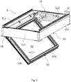
Fig. 4 is a perspective view of a window module in a first embodiment of the invention, in which the sash of the window module is in an open position; -
Fig. 5 is a view corresponding toFig. 4 , from another angle, with parts of the lifting device being shown in a break-away section of the frame of the window module; -
Fig. 6 is a partial perspective view, on a larger scale, of details of the window module ofFig. 4 ; -
Fig. 7 is a cross-sectional view of details of a frame of the window module forming a ceiling module, and a shaft arrangement of an embodiment of the roof light system according to the invention, in the mounted condition; -
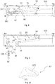
Figs 8 and 9 are cross-sectional views of the window module in the first embodiment of the invention, with the lifting assembly in a first and a second position, corresponding to a closed and an open position of the sash of the window module, sash removed for clarity; -
Fig. 10 is a perspective view of a tool of an embodiment of the roof light system for use with the window module ofFigs 8 and 9 ; -
Figs 11 to 13 are perspective views of the lifting assembly in the first embodiment of the window module according to the invention, in a first, intermediate and second position, respectively; -
Fig. 14 is a plan view, on a larger scale, of a detail of the lifting assembly inFig. 13 ; -
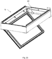
Fig. 15 is a view corresponding toFig. 4 of the window module with a second embodiment of the lifting assembly; -
Figs 16 to 18 are cross-sectional views of the window module in the second embodiment ofFig. 15 , with the lifting assembly in a first, an intermediate and a second position, respectively, corresponding to a closed, an open position and a maximum open position of the sash of the window module, sash removed for clarity; -
Fig. 19 is a partial perspective view, on a larger scale, of a corner of the window module in the second embodiment shown inFig. 18 ; -
Fig. 20 is a view corresponding toFig. 19 of a corner of the window module in a third embodiment; and -
Fig. 21 is a break-out view of details ofFig. 20 . - In the figures of the drawings, embodiments of a window module and a roof light system according to the invention are shown. Initially, a roof light system generally designated 1 and comprising a window module according to the invention forming a
ceiling module 5 of theroof light system 1 will be described. The terms window module and ceiling module will be used alongside each other. The window module according to the invention can also be used in other arrangements, including stand-alone, and in all conceivable orientations other than the shown horizontal, with asash 53 of thewindow module 5 opening downwards. - Referring now to
Fig. 1 , theroof light system 1 is shown in a mounted condition in a roof structure of an inclined roof generally designated 2 within a framework oftrusses vapour barrier 27. Thetrusses battens 26 of theroof 2 are arranged perpendicularly to the counter-battens 25, yet the arrangement thereof can also be in any other plane direction. Theroof light system 1 can be mounted centrally in theroof 2, as shown in the drawing figures, or at the top edge of theroof 2, at the lower part of theroof 2 or at the outer edges of theroof 2. There may be more than oneroof light system 1 installed in theinclined roof 2. - Turning now to
Fig. 2 andFig. 3 , an overview of the components of theroof light system 1 is shown. Theroof light system 1 is configured to provide a light conduit between theinclined roof 2 of a building and aninterior building room 3 with aceiling 31. Theroof light system 1 comprises aroof module 4 with aroof module frame 41 and aroof module pane 42. Theroof module frame 41 defines a length LRM and a width WRM of the roof module in a roof module plane and is configured to be mounted in a surface of theroof 2, e.g. connected to counter-battens 25 and/or thebattens 26 by means of mounting brackets (not shown). In the mounted condition, the roof module plane is substantially parallel to the surface of theroof 2. - As mentioned in the above, the
roof light system 1 further has aceiling module 5 with aceiling module frame 51 and aceiling module pane 52. Theceiling module frame 51 defines a length LCM and a width WCM of theceiling module 5 in a ceiling module plane and is configured to be mounted in theceiling 31, e.g. connected to thetrusses ceiling 31. - In the shown embodiment, the
roof light system 1 further comprises ashaft arrangement 6 extending between theroof module 4 and theceiling module 5. In the mounted condition, said shaft comprises twoside sections first end section 63 and asecond end section 64. Eachside section top edge portion 611 with a length substantially corresponding to a length of the roof module which is in connection with theroof module 4. Theside sections bottom edge portion 612 with a length substantially corresponding to a length of theceiling module 5 being connected to theceiling module 5. Eachside section side edge portion 613 and a secondside edge portion 614 for connection with the first andsecond end sections second end sections end sections side sections roof module 4 and theceiling module 5. - To support the
shaft arrangement 6 in the mounted condition, theroof light system 1 furthermore comprises asupport assembly 7. Components forming part of thesupport assembly 7 comprisebrackets - Referring now in particular to
Fig. 4 , the configuration of theceiling module 5 will be described in more detail and will in the following be referred to as awindow module 5 in a first embodiment. - The terms "left-hand", "right-hand" etc. are used for facilitating the reading and is not to be considered limiting. In the present context, the left-hand side is the side of the roof light system seen from the inside and in the direction from the high end to the low end. Correspondingly, when referring to the members of the window module frame and sash, terms such as "side member", "first end member", "second end member" are used for denoting directions only.
- The
window module 5 comprises aframe 51 and asash 53 provided with apane 52 and hinged to theframe 51 in ahinge connection 54 defining a hinge axis and allowing thesash 53 to swing out of the window module plane from a closed position to an open position about the hinge axis. A liftingassembly 10 is configured to modulate the swinging movement of thesash 53. Terms such as "lifting" and "modulate" are intended to be interpreted in their broadest scope and encompass movements including swinging upwards, downwards and sideward, and that the movements are balanced in the broadest sense, assisted, dampened, braked or checked. - The
frame 51 of theceiling module 5 comprises twoside members second end members sash 53 of theceiling module 5 comprises twoside members second end members hinge connection 54 is connected to a set ofside members frame 51 and thesash 53, respectively. Thehinge connection 54 comprises aframe hinge part 541 and asash hinge part 542. - Referring briefly to
Fig. 7 , other details of theceiling module 5 at the ceiling are shown, including connecting means for the corresponding section of the shaft arrangement comprising agroove profile 55 and acompression profile 56. Furthermore, atrim profile 57 is provided, connected to theceiling module frame 51 by a set of clips 68. Finally, aceiling trim frame 59 is connected to theceiling module frame 51 to span the transition to theceiling 31 in the mounted condition. - A lifting
assembly 10 is in the embodiment shown connected to each first andsecond end member frame 51 of theceiling module 5, and is connected or connectable to thesash 53 of theceiling module 5 as will be described in more detail below. In principle, only one liftingassembly 10 could be present. Likewise, the lifting assembly or lifting assemblies could be located at the side member(s) of the frame and sash in case the hinge connection is located at the first or second end member. - The lifting
assembly 10 comprises aframe base plate 11 configured to be connected to theframe 51, asash base plate 12 configured to be connected to thesash 53, a linkage mechanism including amain link 13 connected to theframe base plate 11 in a first hinged joint 131, and asash link 14 connected to thesash base plate 12 in a sash-side hinged joint 141. In the embodiment shown in the drawings, themain link 13 has a generally triangular plate-shaped configuration, but other shapes are conceivable. - The
sash link 14 is connected to themain link 13 in a second hinged joint 132. Here, thesash link 14 has the form of a substantially straight, plane plate element. - A
spring device 15 having two ends is provided and connected at one end to themain link 13 in a third hinged joint 133 and at the other end configured to be connected to theframe base plate 11 or theframe 51 of thewindow module 5 in a frame-side hinged joint 151. Thespring device 15 may in principle have any configuration extending between two ends, but is typically linear with a substantially longer length than cross-sectional dimensions. - The lifting
assembly 10 is configured to assume a first position corresponding to the closed position of thesash 53 of thewindow module 5 and be moved to a second position corresponding to the open position of thesash 53. In order to modulate the movement of thesash 53, thespring device 15 is biased in at least one of the first and second positions. In the configuration shown in the drawings, thesash 53 opens downwards, and the liftingassembly 10 is here configured to assist in the closing movement to facilitate the operation. To this end, thespring device 15 is configured to be biased during the opening movement and then to release the accumulated energy during the closing movement. In the embodiment shown, the liftingassembly 10 also dampens the movement of thesash 53 during opening. The dampening provided by the lifting assembly is advantageously provided in that thespring device 15 has a dampening effect on the movement between the first and second positions, and/or vice versa. - In principle, the lifting
assembly 10 could rely on mechanical tensioning means such as a pressure spring. In the embodiments shown in the drawings, however, the spring device comprises a pressurised cylinder of a suitable kind, in particular agas spring 15. A gas spring is known to have excellent performance in pushing as well as pulling actions, and it is also possible to incorporate a dampening effect. The dampening effect provides for an improved user experience. This applies during normal operation of thewindow module 5, i.e. when opening and closing thesash 53, which is able to be performed in smooth movements. The dampenedgas spring 15 also has a vital function when the liftingassembly 10 is to be connected to thesash 53 and hence to theframe 51 in the procedure of bringing thewindow module 5 from its supply condition to a mounted condition, corresponding to normal use of thewindow module 5, as will be described in further detail below. - Turning now to
Figs 8 to 14 , details of the lifting assembly in a presently preferred embodiment will be described. In particular,Fig. 11 indicates a majority of the components of the liftingassembly 10, whereas reference numerals are not present in all of the other figures for ease of readability. As shown, thegas spring 15 is provided with acylinder 152 and apiston rod 153. - In this embodiment, the frame-side hinged joint 151 is connected to the
piston rod 153 and the third hinged joint 133 of themain link 13 to thecylinder 152 of thegas spring 15. - The third hinged joint 133 of the
main link 13 is connected to thecylinder 152 of thegas spring 15 via anextension plate 154. In order to allow the components of the linkage mechanism and the spring device to move relative to each other, theextension plate 154 is proved with anangled connection flange 155 which forms the connection at one end of thegas spring 15. - The
frame base plate 11 of the first embodiment has such dimensions that the remaining components of the liftingassembly 10 located in within the contours of theframe base plate 11 in the first position of the liftingassembly 10 as shown inFig. 8 . Thus, in this embodiment the frame-side hinged joint 151 is connected to theframe base plate 11. The liftingassembly 10 of the first embodiment may thus be provided as a coherent unit, and either be connected to thefirst end member 512 of theframe 51 of themodule 5 in the supply condition, or be connected to theframe 51 at the site of installation. Even though thewindow module 5 may be delivered as a unit including theframe 51, thesash 53 and the liftingassembly 10 connected to theframe 51 and to thesash 51, it is preferred that it is possible to disassemble thesash 53 from theframe 51 in order to facilitate other installation work. - Referring in particular to the details of
Figs 8 and11 , the liftingassembly 10 may be connected to only theframe 51 of thewindow module 5 in a supply condition of thewindow module 5. Thus, during transportation of thewindow module 5, which typically takes place in a cardboard box, theframe base plate 11 is connected to thefirst end member 512 of theframe 5. Another liftingassembly 10 may be present at thesecond end member 514. Thegas spring 15 is only connected to the other components of the liftingassembly 10 at its cylinder end, that is to theextension plate 154 and in turn to thethird hinge joint 133 of themain link 13. The frame-side hinged joint 151 is not yet connected to theframe base plate 11 and is temporarily held to theframe base plate 11 by a clip or strips. Thesash base plate 12, themain link 13 and thesash link 14 are only bound by the respective hingedjoints gas spring 15. These components may be positioned in an appropriate manner relative to other parts of thewindow module 5, for instance thesash base plate 12 may be placed on top of thesash 53. In order to bring the liftingassembly 10 to the position shown inFigs 8 and11 , and thus its first position, the frame-side hinged joint 151 of the gas spring is released from any temporary holding means and connected to thefirst end member 512 of theframe 5. It is noted that it is only after connection of the liftingassembly 10 also to thesash 53 that the lifting assembly assumes the position shown inFig. 8 . - In order to connect the
sash 53 to theframe 51, thesash hinge part 542 is connected to theframe hinge part 541 in thehinge connection 54 in a first step. Subsequently, or in a separate step, the liftingassembly 10 is brought from its position at thesecond end member 514 of theframe 51 to its second position as shown inFig. 9 before connection to thesash 53 of thewindow module 5. As this entails that thespring device 15 is biased from its relaxed position, moving the linkage mechanism and the spring device requires that some force is exerted. To assist in bringing the lifting assembly to the second position ofFig. 9 , atool 17 as shown inFig. 10 may be provided, including ahook 171 and ahandle portion 172. Thehook 171 is used to inserted into anopening 127 in thesash base plate 12 and then pull downwards. As the forces provided by thespring device 15 may be substantial, bringing the liftingassembly 10 from its first position to its second position may require some effort. In this operation, it is of value if thespring device 15 has a dampening effect, as this will soften the movement considerably. - To connect the lifting
assembly 10 to thesash 53 of thewindow module 5, thesash base plate 12 is provided with a set ofspigots 126 to be received in a corresponding set ofapertures 536 in amember 533 of thesash 53 of thewindow module 5. As shown inFig. 6 , the set ofapertures 536 is provided in arecess 535. - During operation of the
window module 5 in the mounted condition, thesash 53 is rotated about the hinge axis defined by thehinge 54, out of the window module plane, and downwards in the embodiment of the roof light system shown. The linkage mechanism of the liftingassembly 10 moves in substantially the following manner during opening of the sash 53: Thesash base plate 12 follows thesash member 53 in the opening movement in the clockwise direction inFigs 11 to 13 . Thesash link 14 rotates counter-clockwise relative to thesash base plate 12 as it is connected to the sash-sided hinged joint 141 at one end and to the second hingedjoint 132 of themain link 13 at the other end. Themain link 13 rotates in the clockwise direction about the first hinged joint 131 in which themain link 13 is connected to theframe base plate 131. - In the embodiments shown in the drawings, the spring device in the form of
gas spring 15 is arranged as a pressure spring and the bias of thegas spring 15 is more relaxed in the first position of the liftingassembly 10 corresponding to the closed position of thesash 53 of thewindow module 5 and tensioned in the second position corresponding to an open position of thesash 53, as thegas spring 15 is biased during the opening movement of thesash 53. - The spring device, here the
gas spring 15, is compressed during opening, as its connection to themain link 13, here via theextension plate 154 and theangled connection flange 155, namely the third hinged joint 133 moves to the right in these drawing figures. - Comparing
Figs 11, 12 , and13 , it is also seen that a major part of the travel of thepiston rod 153 occurs in the initial stages of the opening movement, and conversely, in the final stages of the closing movement. In other words, the gearing of the linkingassembly 10 is higher at small angles between thesash 53 and the window module plane. - As the space between the
sash 53 and theframe 51 is limited, but the components of the liftingassembly 10 need to be able to move relative to each other, thesash link 14 is provided with an offset 142. Furthermore, arecess 515 may be present in theend members Fig. 5 . - In the alternative, second embodiment of the
window module 5 shown inFigs 15 to 19 , the liftingassembly 10 is of a more simple configuration. All principal components are the same as in the above embodiments though, and only differences will be described in detail. Elements having the same or analogous function will be denoted by the same reference numerals. - One difference is that the frame-side hinged joint 151 is connected to the
cylinder 152 and the third hinged joint 133 of themain link 13 to thepiston rod 153 of thegas spring 15. - The
frame base plate 11 of the liftingassembly 10 in the second embodiment has smaller dimensions than the counterpart frame base plate of the first embodiment. Thus, the frame-side hinged joint 151 is configured to be connected to theframe 51 of thewindow module 5, rather than to theframe base plate 11. - Referring to the detailed view of
Fig. 19 , it is shown how, in the second embodiment, themain link 13 is provided with an offset 136. A further detail visible inFig. 19 is anopening 113 in theframe base plate 11 for atrim clip 58. - In a further, third embodiment of the
window module 5 shown inFigs 20 and 21 , the liftingassembly 10 is of substantially the same configuration as in the second embodiment. All principal components are the same as in the above embodiments though, and only differences will be described in detail. Elements having the same or analogous function will be denoted by the same reference numerals. - In this embodiment, the
main link 13 is provided with aguide pin 137 which is received in an arc-shapedtrack 516 in thefirst end member 512 of theframe 51. Further details ofFigs 20 and 21 will be described below. - Common to the above embodiments is that the lifting
assembly 10 is configured to assume a second position in which thesash 53 of thewindow module 5 is swung out of the window module plane to a maximum opening angle of substantially 90°. - In order to ensure that the
sash 53 stays in place in maximum opening position, locking means are provided in both embodiments for locking thesash 53 of thewindow module 5 in the maximum opening angle. - In the second embodiment, the locking means comprise a
lock hole 135 in themain link 13 and alock hole 112 in theframe base plate 11. A screw, not shown, is screwed into thefirst end member 512 of theframe 51 at thelock hole 112 in theframe base plate 11. Once the lockingassembly 10 has assumed the position shown inFig. 19 in the maximum opening angle of thesash 53 of thewindow module 5, thelock hole 135 in themain link 13 is in an overlapping position with thelock hole 112 in theframe base plate 11. Now, the screw is screwed slightly out of thefirst end member 512 of theframe 51 and into corresponding threading of thelock hole 112 in themain link 13. To release the locking means, the screw is screwed inwards again to release the engagement with themain link 13. The components of the liftingassembly 10 are then again able to move relative to each other and closing of thesash 53 is possible. - In the first embodiment, the lifting
assembly 10 furthermore comprises aguide link 16 connected to themain link 13 in a fourth hinged joint 134. Theguide link 16 is provided with astraight track portion 161 and an angledlock track portion 162 to receive apin 111 on theframe base plate 11. Once the maximum opening angle has been reached as shown inFig. 13 , the angledlock track portion 162 is engaged with thepin 111 by rotation of theguide link 16 as indicated by arrow A. To release the engagement, theguide link 16 is rotated in the opposite direction such that thepin 111 is again located in thestraight track portion 161. The components of the liftingassembly 10 are then again able to move relative to each other and closing of thesash 53 is possible. - In order to prevent the
sash 53 from opening further than the maximum opening angle, and hence that the liftingassembly 10 is protected from being brought beyond its second position, means may be provided to limit the movement. - In the first embodiment, these means are provided by the
angled track portion 162. - In the second and third embodiments, the movement limiting means are provided by an
end stop 116 on theframe base plate 11 cooperating with theguide pin 137 on themain link 13. Theframe base plate 11 is furthermore provided with an arc-shapedguide edge 15. - It is also possible to provide means for limiting the movement of the lifting
assembly 10 in the first position. This is relevant in case thesash 53 is not in itself prevented from "over-closing" by theframe 51, but also before the liftingassembly 10 is connected to thewindow module 5, since the movement limiting means then prevent themain link 13 from rotating out of its intended angle range. As shown inFigs 19 and20 , such movement limiting means are here provided as afirst end stop 114 at one end of the arc-shapedguide edge 115, the end stop for limiting the movement of the liftingassembly 10 in the second position to prevent "over-opening" being provided as thesecond end stop 116. - Finally, means may be provided for controlling the movement of the
linkage mechanism spring device 15 in a direction perpendicular to theframe base plate 11. This can be provided in any suitable manner, for instance it is conceivable that theguide pin 137 has a retaining function of themain link 13 relative to the guide track as indicated inFig. 21 , where theguide pin 137 has a head portion on the back side of theframe base plate 11 at the arc-shapedguide edge 115, or by a set of further pins or flanges cooperating with the main link and/or the sash link, not shown in detail. - The invention is not limited to the embodiments shown and described in the above, but various modifications and combinations may be carried out.
-
- 1
- roof light system
- 2
- roof
21-24 trusses
25 counter-batten
26 batten
27 vapour barrier
3 interior building room
31 ceiling
32 wall - 4
- roof module
41 roof module frame
411 side member
412 bottom member
42 roof module pane
43 flashing - 5
- window module/ceiling module
51 frame
511 side member
512 first end member
513 side member
514 second end member
515 recess
516 arc-shaped track
52 pane
53 sash
531 side member
532 first end member
533 side member
534 second end member
535 recess
536 apertures
54 hinge connection
541 frame hinge part
542 sash hinge part
55 groove profile
56 compression profile
57 trim profile
58 clip (for trim profile)
59 ceiling trim frame - 6
- shaft arrangement
61 side section (left-hand)
611 top edge portion
612 bottom edge portion
613 first side edge portion (low)
614 second side edge portion (high)
62 side section (right-hand)
63 first end section (low)
64 second end section (high)
7 support assembly
72 bracket
73 bracket
81 first corner post
83 third corner post - 10
- lifting assembly
11 frame base plate
111 pin on frame base plate
112 lock hole in frame base plate
113 opening (for trim clip)
114 first position end stop
115 arc-shaped guide edge
116 second position end stop
12 sash base plate
126 spigots
127 opening (for tool 17)
13 main link
131 first hinged joint of main link
132 second hinged joint of main link
133 third hinged joint of main link
134 fourth hinged joint of main link
135 lock hole in main link
136 offset
137 guide pin on main link
14 sash link
141 sash-side hinged joint
142 offset
15 spring device/gas spring
151 frame-side hinged joint of gas spring
152 cylinder
153 piston rod
154 extension plate
155 angled connection flange
16 guide link
161 straight track portion in guide link
162 angled lock track portion in guide link
17 tool
171 hook on tool
172 handle portion of tool - A
- arrow
- LRM
- length of roof module
- WRM
- width of roof module
- LCM
- length of ceiling module
- WCM
- width of ceiling module
Claims (21)
- A window module (5) comprising a frame (51) defining a length (LCM) and a width (WCM) of the window module in a window module plane, and a sash (53) with a pane (52), said sash (53) being hinged to the frame (51) in a hinge connection (54) defining a hinge axis and allowing the sash (53) to swing out of the window module plane from a closed position to an open position about the hinge axis, and a lifting assembly (10) configured to modulate the swinging movement of the sash (53),
characterised in that
the lifting assembly (10) comprises a frame base plate (11) connected to or connectable to the frame (51), a sash base plate (12) connected to or connectable to the sash (53), a linkage mechanism including a main link (13) connected to the frame base plate (11) in a first hinged joint (131), and a sash link (14) connected to the sash base plate (12) in a sash-side hinged joint (141),
that the sash link (14) is connected to the main link (13) in a second hinged joint (132),
that a spring device (15) having two ends is provided and connected at one end to the main link (13) in a third hinged joint (133) and at the other end connected to or connectable to the frame base plate (11) or the frame (51) of the window module (5) in a frame-side hinged joint (151), and
that the lifting assembly (10) is configured to assume a first position corresponding to the closed position of the sash (53) of the window module (5) and be moved to a second position corresponding to an open position of the sash (53), the spring device (15) being biased in at least one of the first and second positions. - A window module (5) according to claim 1, wherein the spring device comprises a pressurised cylinder device comprising a gas spring (15) with a cylinder (152) and a piston rod (153), preferably having a dampening effect on the movement between the first and second positions, and/or vice versa.
- A window module (5) according to claim 2, wherein the frame-side hinged joint (151) is connected to the cylinder (152) and the third hinged joint (133) of the main link (13) to the piston rod (153) of the gas spring (15), the frame-side hinged joint (151) being preferably connected to the frame (51) of the window module (5).
- A window module (5) according to claim 2, wherein the frame-side hinged joint (151) is connected to the piston rod (153) and the third hinged joint (133) of the main link (13) to the cylinder (152) of the gas spring (15), the third hinged joint (133) of the main link (13) being preferably connected to the cylinder (152) of the gas spring (15) via an extension plate (154), more preferably via an angled connection flange (155).
- A window module (5) according to claim 4, wherein the frame-side hinged joint (151) is connected to the frame base plate (11).
- A window module (5) according to any one of the preceding claims, wherein the lifting assembly (10) is configured to assume a second position in which the sash (53) of the window module (5) is swung out of the window module plane to a maximum opening angle of substantially 90°.
- A window module (5) according to claim 6, wherein locking means are provided for locking the sash (53) of the window module (5) in the maximum opening angle.
- A window module (5) according to claim 7, wherein the locking means comprise a lock hole (135) in the main link (13), a lock hole (112) in the frame base plate (11) and a screw in the frame (51), and wherein the screw is screwed out of the frame (51) and into the lock hole (135) in the main link (13) when the lock hole (135) in the main link (13) and the lock hole (112) in the frame base plate (11) are in an overlapping position in the maximum opening angle of the sash (53) of the window module (5).
- A window module (5) according to claim 7, wherein the lifting assembly (10) furthermore comprises a guide link (16) connected to the main link (13) in a fourth hinged joint (134), the guide link (16) being provided with a straight track portion (161) and an angled lock track portion (162) to receive a pin (111) on the frame base plate (11), said angled lock track portion (162) being engageable with the pin (111) in the maximum opening angle of the sash (53) of the window module (5) by rotation of the guide link (16).
- A window module (5) according to any one of claims 6 to 9, wherein means are provided for limiting the movement of the lifting assembly (10) and in turn the sash (53) in the maximum opening angle.
- A window module (5) according to claims 9 and 10, wherein the movement limiting means are provided by the angled track portion (162).
- A window module (5) according to claims 8 and 10, wherein the movement limiting means are provided by an end stop (116) on the frame base plate (11) cooperating with a guide pin (137) on the main link (13), and optionally, said frame base plate (11) is provided with an arc-shaped guide edge (115), the guide pin (137) being preferably received in an arc-shaped track (516) in a member (512) of the frame (51).
- A window module (5) according to any one of the preceding claims, wherein means are provided for limiting the movement of the lifting assembly (10) in a supply condition.
- A window module (5) according to claims 12 and 13, wherein the movement limiting means are provided with a first end stop (114) at one end of the arc-shaped guide edge (115), the end stop for limiting the movement of the lifting assembly (10) in the second position being provided as a second end stop (116).
- A window module (5) according to any one of the preceding claims, wherein means are provided for controlling the movement of the linkage mechanism (13, 14) and the spring device (15) in a direction perpendicular to the frame base plate (11).
- A window module (5) according to any one of the preceding claims, wherein the spring device (15) is arranged as a pressure spring and the bias of the spring device (15) is more relaxed in the first position of the lifting assembly (10) corresponding to the closed position of the sash (53) of the window module (5) and tensioned in the second position corresponding to an open position of the sash (53).
- A window module (5) according to claim 16, wherein the lifting assembly (10) is connected to only the frame (51) of the window module (5) in a supply condition of the window module (5), and assuming a position, with the spring device (15) in its relaxed condition, the sash (53) being preferably configured to be connected to the frame (51) at the hinge connection (54) in the supply condition and is opened to an intermediate condition, and the lifting assembly (10) is configured to be brought from its first position to its second position before connection to the sash (53) of the window module (5) in the intermediate condition of the sash (53), preferably by means of a tool (17) insertable into an opening (127) in the sash base plate (12).
- A window module (5) according to any one of the preceding claims, wherein the sash base plate (12) is provided with a set of spigots (126) to be received in a corresponding set of apertures (536) in a member (533) of the sash (53) of the window module (5), said set of apertures (536) being preferably provided in a recess (535).
- A window module (5) according to any one of the preceding claims, wherein the sash link (14) and/or the main link (13) is/are provided with an offset (142; 136).
- A roof light system (1) configured to provide a light conduit between an inclined roof (2) of a building and an interior building room (3) with a ceiling (31) in a mounted condition, comprising:a roof module (4) comprising a roof module frame (41) and a roof module pane (42), said roof module frame (41) defining a length (LRM) and a width (WRM) of the roof module in a roof module plane and being configured to be mounted in a surface of the roof (2) in the mounted condition, with the roof module plane substantially parallel to the roof surface,a ceiling module (5) comprising at least a ceiling module frame (51) and a ceiling module pane (52), said ceiling module frame (51) defining a length (LCM) and a width (WCM) of the ceiling module in a ceiling module plane and being configured to be mounted in the ceiling (31) in the mounted condition, with the ceiling module plane substantially parallel to the ceiling, anda shaft arrangement (6) extending between the roof module (4) and the ceiling module (5) in the mounted condition, said shaft comprising two side sections (61, 62), a first end section (63) and a second end section (64), in which each side section (61, 62) has a top edge portion (611) with a length substantially corresponding to a length of the roof module, a bottom edge portion (612) with a length substantially corresponding to a length of the ceiling module, a first side edge portion (613) and a second side edge portion (614), and in which each of the first and second end sections (63, 64) has a top edge, a bottom edge and two side edges,characterised in thatthe ceiling module comprises a window module (5) according to any one of claims 1 to 19 and the sash (53) is configured to be opened into the interior building room.
- A roof light system according to claim 20, wherein the frame (51) of the ceiling module (5) comprises two side members (511, 513) and first and second end members (512, 514), and the sash (53) of the ceiling module (5) comprises two side members (531, 533) and first and second end members (532, 534), wherein the hinge connection (54) is connected to a set of side members (511, 531) of the frame (51) and the sash (53) and wherein one lifting assembly (10) is connected to each first and second end member (512, 514) of the frame (51) of the ceiling module (5), and wherein the lifting assembly (10) is connected or connectable to the sash (53) of the ceiling module (5).
Applications Claiming Priority (1)
| Application Number | Priority Date | Filing Date | Title |
|---|---|---|---|
| DKPA201970562 | 2019-09-06 |
Publications (2)
| Publication Number | Publication Date |
|---|---|
| EP3792423A1 true EP3792423A1 (en) | 2021-03-17 |
| EP3792423B1 EP3792423B1 (en) | 2022-08-17 |
Family
ID=72428150
Family Applications (1)
| Application Number | Title | Priority Date | Filing Date |
|---|---|---|---|
| EP20194847.8A Active EP3792423B1 (en) | 2019-09-06 | 2020-09-07 | Window module with lifting assembly, and roof light system comprising such a window module as a ceiling module |
Country Status (1)
| Country | Link |
|---|---|
| EP (1) | EP3792423B1 (en) |
Cited By (1)
| Publication number | Priority date | Publication date | Assignee | Title |
|---|---|---|---|---|
| CN117211477A (en) * | 2023-11-07 | 2023-12-12 | 江苏阔能建材科技有限公司 | Roof electric opening window based on intelligent building |
Citations (15)
| Publication number | Priority date | Publication date | Assignee | Title |
|---|---|---|---|---|
| DE2852915A1 (en) * | 1978-04-10 | 1980-06-19 | Kloeber Fa Hans | Roof skylight opening and positioning mechanism - has angled, lug swivelling slots with widened end for lug collar |
| DE3133801A1 (en) * | 1980-09-04 | 1982-06-03 | Arthur Shaw Mfg. Ltd., Willenhall, West Midlands | Friction support for windows |
| DE3338092A1 (en) * | 1983-10-20 | 1985-05-02 | Fa. J. Eberspächer, 7300 Esslingen | Apparatus for extracting smoke and heat and also for the ventilation and venting of closed areas |
| DE8816626U1 (en) * | 1988-05-20 | 1990-01-25 | HEIM und HAUS Vertriebsgesellschaft für Kunststoffenster und -rolläden mbH, 4100 Duisburg | Roof window shutters |
| US5613333A (en) | 1994-09-16 | 1997-03-25 | Witzig, Jr.; Michael J. | Motorized skylight assembly for mounting on the roof of a building |
| EP1103690A1 (en) * | 1999-11-27 | 2001-05-30 | Josef Fortmeier | Fume venting device |
| US6604329B2 (en) | 1999-11-19 | 2003-08-12 | Fox Lite, Inc. | Light conducting tube for a skylight |
| US20040043722A1 (en) * | 2002-08-27 | 2004-03-04 | Suspa Holding Gmbh | Opening flap, in particular flue gas escape flap, and opening mechanism therefor |
| US20050081462A1 (en) | 2003-10-17 | 2005-04-21 | Mulford Travis M. | Skylight kit and method |
| US20070264924A1 (en) * | 2004-09-21 | 2007-11-15 | Pilkington Automo Tive Finland Oy | Vehicle Glazing |
| EP1756481B1 (en) | 2004-04-19 | 2008-07-30 | VKR Holding A/S | Roof light system having an improved ventilation device |
| EP1756482B1 (en) | 2004-04-19 | 2008-07-30 | VKR Holding A/S | Roof light system comprising optional elements and interchangeable parts |
| EP1841931B1 (en) | 2005-01-24 | 2011-12-14 | VKR Holding A/S | Roof light system having a ventilation device with improved flexibility |
| EP2423406A1 (en) * | 2010-08-31 | 2012-02-29 | Paolo Caoduro | Opening skylight with improved cover constraining means |
| JP2012160288A (en) * | 2011-01-31 | 2012-08-23 | Takiron Co Ltd | Daylighting section and daylighting device using such daylighting section |
-
2020
- 2020-09-07 EP EP20194847.8A patent/EP3792423B1/en active Active
Patent Citations (15)
| Publication number | Priority date | Publication date | Assignee | Title |
|---|---|---|---|---|
| DE2852915A1 (en) * | 1978-04-10 | 1980-06-19 | Kloeber Fa Hans | Roof skylight opening and positioning mechanism - has angled, lug swivelling slots with widened end for lug collar |
| DE3133801A1 (en) * | 1980-09-04 | 1982-06-03 | Arthur Shaw Mfg. Ltd., Willenhall, West Midlands | Friction support for windows |
| DE3338092A1 (en) * | 1983-10-20 | 1985-05-02 | Fa. J. Eberspächer, 7300 Esslingen | Apparatus for extracting smoke and heat and also for the ventilation and venting of closed areas |
| DE8816626U1 (en) * | 1988-05-20 | 1990-01-25 | HEIM und HAUS Vertriebsgesellschaft für Kunststoffenster und -rolläden mbH, 4100 Duisburg | Roof window shutters |
| US5613333A (en) | 1994-09-16 | 1997-03-25 | Witzig, Jr.; Michael J. | Motorized skylight assembly for mounting on the roof of a building |
| US6604329B2 (en) | 1999-11-19 | 2003-08-12 | Fox Lite, Inc. | Light conducting tube for a skylight |
| EP1103690A1 (en) * | 1999-11-27 | 2001-05-30 | Josef Fortmeier | Fume venting device |
| US20040043722A1 (en) * | 2002-08-27 | 2004-03-04 | Suspa Holding Gmbh | Opening flap, in particular flue gas escape flap, and opening mechanism therefor |
| US20050081462A1 (en) | 2003-10-17 | 2005-04-21 | Mulford Travis M. | Skylight kit and method |
| EP1756481B1 (en) | 2004-04-19 | 2008-07-30 | VKR Holding A/S | Roof light system having an improved ventilation device |
| EP1756482B1 (en) | 2004-04-19 | 2008-07-30 | VKR Holding A/S | Roof light system comprising optional elements and interchangeable parts |
| US20070264924A1 (en) * | 2004-09-21 | 2007-11-15 | Pilkington Automo Tive Finland Oy | Vehicle Glazing |
| EP1841931B1 (en) | 2005-01-24 | 2011-12-14 | VKR Holding A/S | Roof light system having a ventilation device with improved flexibility |
| EP2423406A1 (en) * | 2010-08-31 | 2012-02-29 | Paolo Caoduro | Opening skylight with improved cover constraining means |
| JP2012160288A (en) * | 2011-01-31 | 2012-08-23 | Takiron Co Ltd | Daylighting section and daylighting device using such daylighting section |
Cited By (2)
| Publication number | Priority date | Publication date | Assignee | Title |
|---|---|---|---|---|
| CN117211477A (en) * | 2023-11-07 | 2023-12-12 | 江苏阔能建材科技有限公司 | Roof electric opening window based on intelligent building |
| CN117211477B (en) * | 2023-11-07 | 2024-02-13 | 江苏阔能建材科技有限公司 | Roof electric opening window based on intelligent building |
Also Published As
| Publication number | Publication date |
|---|---|
| EP3792423B1 (en) | 2022-08-17 |
Similar Documents
| Publication | Publication Date | Title |
|---|---|---|
| US6883273B2 (en) | Hydraulically operated overhead door | |
| RU2184829C1 (en) | Mansard dormer window with facing members of window-frame and leaf | |
| US5383509A (en) | Kit for door reinforcement | |
| CN102535716B (en) | Install and include the method for the window device of multiple adjacent windows and such window device | |
| ITVR20090187A1 (en) | DEVICE FOR PROTECTION AGAINST ATMOSPHERIC FRAMES FOR ROOFING OR SIMILAR | |
| US20080060274A1 (en) | In joinery | |
| US20080235910A1 (en) | Hinge | |
| EP3792423B1 (en) | Window module with lifting assembly, and roof light system comprising such a window module as a ceiling module | |
| JPH01247683A (en) | Window device for emergency exit | |
| US7891401B2 (en) | Systems for bracing garage doors against hurricane force winds | |
| CN107835885B (en) | flood gate | |
| US4564975A (en) | Hinge hardware element for doors and windows of building and furniture | |
| JP2009191484A (en) | Opening restriction device and fitting | |
| US20250376883A1 (en) | Enclosure configuration systems and methods | |
| US20050016068A1 (en) | Garage door opener | |
| EP2231977B1 (en) | A window, a method for mounting a window, and a window including a set of parts | |
| PL230248B1 (en) | Rooflight with lifted sash, preferably with smoke extraction function | |
| CN208122587U (en) | A kind of locking of worm and gear link type and its tunnel protection door or Dong Shimen for tunnel protection door or cavern's door | |
| KR100677937B1 (en) | Revolving Security Window for Apartment Houses | |
| CN222542271U (en) | A rescue window structure suitable for broken line corners | |
| CN224120117U (en) | A prefabricated fire door with fasteners | |
| WO2024156278A1 (en) | Steel pergola | |
| CN221920747U (en) | Residential indoor laminating type wooden fireproof door | |
| CN224227964U (en) | Assembled steel construction intelligent building | |
| CN216003726U (en) | Fireproof door convenient to transport |
Legal Events
| Date | Code | Title | Description |
|---|---|---|---|
| PUAI | Public reference made under article 153(3) epc to a published international application that has entered the european phase |
Free format text: ORIGINAL CODE: 0009012 |
|
| STAA | Information on the status of an ep patent application or granted ep patent |
Free format text: STATUS: THE APPLICATION HAS BEEN PUBLISHED |
|
| AK | Designated contracting states |
Kind code of ref document: A1 Designated state(s): AL AT BE BG CH CY CZ DE DK EE ES FI FR GB GR HR HU IE IS IT LI LT LU LV MC MK MT NL NO PL PT RO RS SE SI SK SM TR |
|
| AX | Request for extension of the european patent |
Extension state: BA ME |
|
| STAA | Information on the status of an ep patent application or granted ep patent |
Free format text: STATUS: REQUEST FOR EXAMINATION WAS MADE |
|
| 17P | Request for examination filed |
Effective date: 20211217 |
|
| RBV | Designated contracting states (corrected) |
Designated state(s): AL AT BE BG CH CY CZ DE DK EE ES FI FR GB GR HR HU IE IS IT LI LT LU LV MC MK MT NL NO PL PT RO RS SE SI SK SM TR |
|
| GRAP | Despatch of communication of intention to grant a patent |
Free format text: ORIGINAL CODE: EPIDOSNIGR1 |
|
| STAA | Information on the status of an ep patent application or granted ep patent |
Free format text: STATUS: GRANT OF PATENT IS INTENDED |
|
| RIC1 | Information provided on ipc code assigned before grant |
Ipc: E05C 17/00 20060101ALI20220214BHEP Ipc: E05F 1/10 20060101ALI20220214BHEP Ipc: F21S 11/00 20060101ALI20220214BHEP Ipc: E04D 13/03 20060101AFI20220214BHEP |
|
| INTG | Intention to grant announced |
Effective date: 20220322 |
|
| GRAS | Grant fee paid |
Free format text: ORIGINAL CODE: EPIDOSNIGR3 |
|
| GRAA | (expected) grant |
Free format text: ORIGINAL CODE: 0009210 |
|
| STAA | Information on the status of an ep patent application or granted ep patent |
Free format text: STATUS: THE PATENT HAS BEEN GRANTED |
|
| AK | Designated contracting states |
Kind code of ref document: B1 Designated state(s): AL AT BE BG CH CY CZ DE DK EE ES FI FR GB GR HR HU IE IS IT LI LT LU LV MC MK MT NL NO PL PT RO RS SE SI SK SM TR |
|
| REG | Reference to a national code |
Ref country code: CH Ref legal event code: EP |
|
| REG | Reference to a national code |
Ref country code: DE Ref legal event code: R096 Ref document number: 602020004555 Country of ref document: DE |
|
| REG | Reference to a national code |
Ref country code: IE Ref legal event code: FG4D |
|
| REG | Reference to a national code |
Ref country code: AT Ref legal event code: REF Ref document number: 1512277 Country of ref document: AT Kind code of ref document: T Effective date: 20220915 |
|
| REG | Reference to a national code |
Ref country code: NL Ref legal event code: MP Effective date: 20220817 |
|
| REG | Reference to a national code |
Ref country code: LT Ref legal event code: MG9D |
|
| PG25 | Lapsed in a contracting state [announced via postgrant information from national office to epo] |
Ref country code: SE Free format text: LAPSE BECAUSE OF FAILURE TO SUBMIT A TRANSLATION OF THE DESCRIPTION OR TO PAY THE FEE WITHIN THE PRESCRIBED TIME-LIMIT Effective date: 20220817 Ref country code: RS Free format text: LAPSE BECAUSE OF FAILURE TO SUBMIT A TRANSLATION OF THE DESCRIPTION OR TO PAY THE FEE WITHIN THE PRESCRIBED TIME-LIMIT Effective date: 20220817 Ref country code: PT Free format text: LAPSE BECAUSE OF FAILURE TO SUBMIT A TRANSLATION OF THE DESCRIPTION OR TO PAY THE FEE WITHIN THE PRESCRIBED TIME-LIMIT Effective date: 20221219 Ref country code: NO Free format text: LAPSE BECAUSE OF FAILURE TO SUBMIT A TRANSLATION OF THE DESCRIPTION OR TO PAY THE FEE WITHIN THE PRESCRIBED TIME-LIMIT Effective date: 20221117 Ref country code: NL Free format text: LAPSE BECAUSE OF FAILURE TO SUBMIT A TRANSLATION OF THE DESCRIPTION OR TO PAY THE FEE WITHIN THE PRESCRIBED TIME-LIMIT Effective date: 20220817 Ref country code: LV Free format text: LAPSE BECAUSE OF FAILURE TO SUBMIT A TRANSLATION OF THE DESCRIPTION OR TO PAY THE FEE WITHIN THE PRESCRIBED TIME-LIMIT Effective date: 20220817 Ref country code: LT Free format text: LAPSE BECAUSE OF FAILURE TO SUBMIT A TRANSLATION OF THE DESCRIPTION OR TO PAY THE FEE WITHIN THE PRESCRIBED TIME-LIMIT Effective date: 20220817 Ref country code: FI Free format text: LAPSE BECAUSE OF FAILURE TO SUBMIT A TRANSLATION OF THE DESCRIPTION OR TO PAY THE FEE WITHIN THE PRESCRIBED TIME-LIMIT Effective date: 20220817 |
|
| REG | Reference to a national code |
Ref country code: AT Ref legal event code: MK05 Ref document number: 1512277 Country of ref document: AT Kind code of ref document: T Effective date: 20220817 |
|
| PG25 | Lapsed in a contracting state [announced via postgrant information from national office to epo] |
Ref country code: PL Free format text: LAPSE BECAUSE OF FAILURE TO SUBMIT A TRANSLATION OF THE DESCRIPTION OR TO PAY THE FEE WITHIN THE PRESCRIBED TIME-LIMIT Effective date: 20220817 Ref country code: IS Free format text: LAPSE BECAUSE OF FAILURE TO SUBMIT A TRANSLATION OF THE DESCRIPTION OR TO PAY THE FEE WITHIN THE PRESCRIBED TIME-LIMIT Effective date: 20221217 Ref country code: HR Free format text: LAPSE BECAUSE OF FAILURE TO SUBMIT A TRANSLATION OF THE DESCRIPTION OR TO PAY THE FEE WITHIN THE PRESCRIBED TIME-LIMIT Effective date: 20220817 Ref country code: GR Free format text: LAPSE BECAUSE OF FAILURE TO SUBMIT A TRANSLATION OF THE DESCRIPTION OR TO PAY THE FEE WITHIN THE PRESCRIBED TIME-LIMIT Effective date: 20221118 |
|
| PG25 | Lapsed in a contracting state [announced via postgrant information from national office to epo] |
Ref country code: SM Free format text: LAPSE BECAUSE OF FAILURE TO SUBMIT A TRANSLATION OF THE DESCRIPTION OR TO PAY THE FEE WITHIN THE PRESCRIBED TIME-LIMIT Effective date: 20220817 Ref country code: RO Free format text: LAPSE BECAUSE OF FAILURE TO SUBMIT A TRANSLATION OF THE DESCRIPTION OR TO PAY THE FEE WITHIN THE PRESCRIBED TIME-LIMIT Effective date: 20220817 Ref country code: ES Free format text: LAPSE BECAUSE OF FAILURE TO SUBMIT A TRANSLATION OF THE DESCRIPTION OR TO PAY THE FEE WITHIN THE PRESCRIBED TIME-LIMIT Effective date: 20220817 Ref country code: DK Free format text: LAPSE BECAUSE OF FAILURE TO SUBMIT A TRANSLATION OF THE DESCRIPTION OR TO PAY THE FEE WITHIN THE PRESCRIBED TIME-LIMIT Effective date: 20220817 Ref country code: CZ Free format text: LAPSE BECAUSE OF FAILURE TO SUBMIT A TRANSLATION OF THE DESCRIPTION OR TO PAY THE FEE WITHIN THE PRESCRIBED TIME-LIMIT Effective date: 20220817 Ref country code: AT Free format text: LAPSE BECAUSE OF FAILURE TO SUBMIT A TRANSLATION OF THE DESCRIPTION OR TO PAY THE FEE WITHIN THE PRESCRIBED TIME-LIMIT Effective date: 20220817 |
|
| REG | Reference to a national code |
Ref country code: DE Ref legal event code: R097 Ref document number: 602020004555 Country of ref document: DE |
|
| REG | Reference to a national code |
Ref country code: BE Ref legal event code: MM Effective date: 20220930 |
|
| PG25 | Lapsed in a contracting state [announced via postgrant information from national office to epo] |
Ref country code: SK Free format text: LAPSE BECAUSE OF FAILURE TO SUBMIT A TRANSLATION OF THE DESCRIPTION OR TO PAY THE FEE WITHIN THE PRESCRIBED TIME-LIMIT Effective date: 20220817 Ref country code: MC Free format text: LAPSE BECAUSE OF FAILURE TO SUBMIT A TRANSLATION OF THE DESCRIPTION OR TO PAY THE FEE WITHIN THE PRESCRIBED TIME-LIMIT Effective date: 20220817 Ref country code: EE Free format text: LAPSE BECAUSE OF FAILURE TO SUBMIT A TRANSLATION OF THE DESCRIPTION OR TO PAY THE FEE WITHIN THE PRESCRIBED TIME-LIMIT Effective date: 20220817 |
|
| PLBE | No opposition filed within time limit |
Free format text: ORIGINAL CODE: 0009261 |
|
| STAA | Information on the status of an ep patent application or granted ep patent |
Free format text: STATUS: NO OPPOSITION FILED WITHIN TIME LIMIT |
|
| PG25 | Lapsed in a contracting state [announced via postgrant information from national office to epo] |
Ref country code: LU Free format text: LAPSE BECAUSE OF NON-PAYMENT OF DUE FEES Effective date: 20220907 Ref country code: AL Free format text: LAPSE BECAUSE OF FAILURE TO SUBMIT A TRANSLATION OF THE DESCRIPTION OR TO PAY THE FEE WITHIN THE PRESCRIBED TIME-LIMIT Effective date: 20220817 |
|
| 26N | No opposition filed |
Effective date: 20230519 |
|
| PG25 | Lapsed in a contracting state [announced via postgrant information from national office to epo] |
Ref country code: IE Free format text: LAPSE BECAUSE OF NON-PAYMENT OF DUE FEES Effective date: 20220907 |
|
| PG25 | Lapsed in a contracting state [announced via postgrant information from national office to epo] |
Ref country code: SI Free format text: LAPSE BECAUSE OF FAILURE TO SUBMIT A TRANSLATION OF THE DESCRIPTION OR TO PAY THE FEE WITHIN THE PRESCRIBED TIME-LIMIT Effective date: 20220817 |
|
| PG25 | Lapsed in a contracting state [announced via postgrant information from national office to epo] |
Ref country code: BE Free format text: LAPSE BECAUSE OF NON-PAYMENT OF DUE FEES Effective date: 20220930 |
|
| PG25 | Lapsed in a contracting state [announced via postgrant information from national office to epo] |
Ref country code: CY Free format text: LAPSE BECAUSE OF FAILURE TO SUBMIT A TRANSLATION OF THE DESCRIPTION OR TO PAY THE FEE WITHIN THE PRESCRIBED TIME-LIMIT Effective date: 20220817 |
|
| REG | Reference to a national code |
Ref country code: CH Ref legal event code: PL |
|
| PG25 | Lapsed in a contracting state [announced via postgrant information from national office to epo] |
Ref country code: MK Free format text: LAPSE BECAUSE OF FAILURE TO SUBMIT A TRANSLATION OF THE DESCRIPTION OR TO PAY THE FEE WITHIN THE PRESCRIBED TIME-LIMIT Effective date: 20220817 Ref country code: IT Free format text: LAPSE BECAUSE OF FAILURE TO SUBMIT A TRANSLATION OF THE DESCRIPTION OR TO PAY THE FEE WITHIN THE PRESCRIBED TIME-LIMIT Effective date: 20220817 Ref country code: HU Free format text: LAPSE BECAUSE OF FAILURE TO SUBMIT A TRANSLATION OF THE DESCRIPTION OR TO PAY THE FEE WITHIN THE PRESCRIBED TIME-LIMIT; INVALID AB INITIO Effective date: 20200907 |
|
| PG25 | Lapsed in a contracting state [announced via postgrant information from national office to epo] |
Ref country code: CH Free format text: LAPSE BECAUSE OF NON-PAYMENT OF DUE FEES Effective date: 20230930 |
|
| PG25 | Lapsed in a contracting state [announced via postgrant information from national office to epo] |
Ref country code: CH Free format text: LAPSE BECAUSE OF NON-PAYMENT OF DUE FEES Effective date: 20230930 Ref country code: BG Free format text: LAPSE BECAUSE OF FAILURE TO SUBMIT A TRANSLATION OF THE DESCRIPTION OR TO PAY THE FEE WITHIN THE PRESCRIBED TIME-LIMIT Effective date: 20220817 |
|
| PG25 | Lapsed in a contracting state [announced via postgrant information from national office to epo] |
Ref country code: MT Free format text: LAPSE BECAUSE OF FAILURE TO SUBMIT A TRANSLATION OF THE DESCRIPTION OR TO PAY THE FEE WITHIN THE PRESCRIBED TIME-LIMIT Effective date: 20220817 |
|
| PGFP | Annual fee paid to national office [announced via postgrant information from national office to epo] |
Ref country code: DE Payment date: 20250805 Year of fee payment: 6 |
|
| PGFP | Annual fee paid to national office [announced via postgrant information from national office to epo] |
Ref country code: GB Payment date: 20250731 Year of fee payment: 6 |
|
| PGFP | Annual fee paid to national office [announced via postgrant information from national office to epo] |
Ref country code: FR Payment date: 20250821 Year of fee payment: 6 |
|
| PG25 | Lapsed in a contracting state [announced via postgrant information from national office to epo] |
Ref country code: TR Free format text: LAPSE BECAUSE OF FAILURE TO SUBMIT A TRANSLATION OF THE DESCRIPTION OR TO PAY THE FEE WITHIN THE PRESCRIBED TIME-LIMIT Effective date: 20220817 |