EP1756482B1 - Roof light system comprising optional elements and interchangeable parts - Google Patents
Roof light system comprising optional elements and interchangeable parts Download PDFInfo
- Publication number
- EP1756482B1 EP1756482B1 EP05731861A EP05731861A EP1756482B1 EP 1756482 B1 EP1756482 B1 EP 1756482B1 EP 05731861 A EP05731861 A EP 05731861A EP 05731861 A EP05731861 A EP 05731861A EP 1756482 B1 EP1756482 B1 EP 1756482B1
- Authority
- EP
- European Patent Office
- Prior art keywords
- roof
- light system
- unit
- frame
- roof light
- Prior art date
- Legal status (The legal status is an assumption and is not a legal conclusion. Google has not performed a legal analysis and makes no representation as to the accuracy of the status listed.)
- Expired - Lifetime
Links
- 238000009423 ventilation Methods 0.000 claims abstract description 72
- 230000007704 transition Effects 0.000 claims description 9
- 239000011248 coating agent Substances 0.000 claims description 6
- 238000000576 coating method Methods 0.000 claims description 6
- 238000005399 mechanical ventilation Methods 0.000 claims description 3
- 230000000153 supplemental effect Effects 0.000 claims description 2
- 238000009434 installation Methods 0.000 description 13
- 239000000463 material Substances 0.000 description 9
- 238000001556 precipitation Methods 0.000 description 5
- 238000011161 development Methods 0.000 description 4
- 239000013589 supplement Substances 0.000 description 4
- XLYOFNOQVPJJNP-UHFFFAOYSA-N water Substances O XLYOFNOQVPJJNP-UHFFFAOYSA-N 0.000 description 4
- 238000009833 condensation Methods 0.000 description 3
- 230000005494 condensation Effects 0.000 description 3
- 229910052602 gypsum Inorganic materials 0.000 description 3
- 239000010440 gypsum Substances 0.000 description 3
- 230000000149 penetrating effect Effects 0.000 description 3
- 238000004891 communication Methods 0.000 description 2
- 239000012530 fluid Substances 0.000 description 2
- 241000238631 Hexapoda Species 0.000 description 1
- 230000000712 assembly Effects 0.000 description 1
- 238000000429 assembly Methods 0.000 description 1
- 230000004888 barrier function Effects 0.000 description 1
- 230000005540 biological transmission Effects 0.000 description 1
- 230000000903 blocking effect Effects 0.000 description 1
- 230000008094 contradictory effect Effects 0.000 description 1
- 230000009977 dual effect Effects 0.000 description 1
- 239000000428 dust Substances 0.000 description 1
- 230000002349 favourable effect Effects 0.000 description 1
- 239000011521 glass Substances 0.000 description 1
- 230000005484 gravity Effects 0.000 description 1
- 230000004941 influx Effects 0.000 description 1
- 230000014759 maintenance of location Effects 0.000 description 1
- 238000004519 manufacturing process Methods 0.000 description 1
- 230000013011 mating Effects 0.000 description 1
- 238000012986 modification Methods 0.000 description 1
- 230000004048 modification Effects 0.000 description 1
- 230000035515 penetration Effects 0.000 description 1
- 238000012216 screening Methods 0.000 description 1
- 238000007789 sealing Methods 0.000 description 1
- 239000007787 solid Substances 0.000 description 1
- 238000006467 substitution reaction Methods 0.000 description 1
- 230000000007 visual effect Effects 0.000 description 1
- 230000003313 weakening effect Effects 0.000 description 1
Images




Classifications
-
- E—FIXED CONSTRUCTIONS
- E04—BUILDING
- E04D—ROOF COVERINGS; SKY-LIGHTS; GUTTERS; ROOF-WORKING TOOLS
- E04D13/00—Special arrangements or devices in connection with roof coverings; Protection against birds; Roof drainage ; Sky-lights
- E04D13/03—Sky-lights; Domes; Ventilating sky-lights
-
- E—FIXED CONSTRUCTIONS
- E04—BUILDING
- E04D—ROOF COVERINGS; SKY-LIGHTS; GUTTERS; ROOF-WORKING TOOLS
- E04D13/00—Special arrangements or devices in connection with roof coverings; Protection against birds; Roof drainage ; Sky-lights
- E04D13/03—Sky-lights; Domes; Ventilating sky-lights
- E04D13/0325—Sky-lights; Domes; Ventilating sky-lights provided with ventilating means
-
- E—FIXED CONSTRUCTIONS
- E04—BUILDING
- E04D—ROOF COVERINGS; SKY-LIGHTS; GUTTERS; ROOF-WORKING TOOLS
- E04D13/00—Special arrangements or devices in connection with roof coverings; Protection against birds; Roof drainage ; Sky-lights
- E04D13/03—Sky-lights; Domes; Ventilating sky-lights
- E04D2013/034—Daylight conveying tubular skylights
- E04D2013/0345—Daylight conveying tubular skylights with skylight shafts extending from roof to ceiling
Definitions
- the present invention relates to a roof light system comprising a roof unit, a light conduit and a diffuser unit, said light conduit extending between a first end positioned at the roof unit and a second end positioned at the diffuser unit.
- EP 0 313 461 discloses such a roof light system according to the preamble of claim 1.
- roof units such as roof windows, skylights and other more or less light transmissible roof penetrating structures provide natural lighting to a space situated immediately below or only a short unobstructed distance from the part of the roof, in which the roof unit is installed.
- artificial lighting has been the dominating source of light.
- a light conduit is led through the roof structure between the roof unit installed in the roof and a diffuser unit installed in the ceiling of an inner room. Light from the ambience is channelled through the light conduit into the inner room.
- the light conduit may e.g. be formed as a length of flexible hose, possibly reinforced by wire hoops, or rigid sections connected with each other to form the desired path of the light conduit between the roof unit and the diffuser unit.
- the internal side of the light conduit is usually provided with a light reflective lining or coating, or the entire material of the light conduit is made from a light reflective material.
- Such a roof light system is traditionally delivered as a set of ready-to-use elements comprising the roof unit, the light conduit and the diffuser unit. Due to the different installation conditions, the light conduit is delivered in a variety of different lengths or even made to custom.
- a ventilation device is usually included in the set. To the manufacturer, this entails that several models must be produced and kept in stock. To the consumer, this might entail that he or she is forced to invest in a system, which contains elements not required or wanted in relation to his or her particular wish.
- a roof light system comprising a roof unit, a light conduit and a diffuser unit, said light conduit extending between a first end positioned at the roof unit and a second end positioned at the diffuser unit, characterized in comprising a base module including the roof unit, the light conduit and the diffuser unit, that the roof unit comprises a frame defining an inner circumference and having a circular aperture and a sash carrying a glazing, said frame and sash having a rectangular shape, said light conduit having a circular shape, and said first end of the light conduit being detachably connected with the frame at said circular aperture, the area between the inner circumference of the frame and the circular aperture constituting a transition area substantially in parallel with the glazing, the roof light system furthermore comprising optional elements adapted to be connected with the base module, and interchangeable elements to replace elements of at least the roof unit and the light conduit of the base module.
- a functional roof light system is achieved.
- this may be accomplished by means of the optional elements or by interchanging one or more elements of the base module with other elements.
- the replacement or addition of elements is facilitated by the fact that the light conduit is detachably connected with the roof unit at the area of transition between the light conduit and the roof unit.
- the light conduit may be made to custom, a ventilation device may be delivered separately, or the roof light system may be transformed into a more traditional, openable roof window.
- the differences in shape between the frame and the light admitting aperture entails that light directed to the transition area, i.e. outside the aperture, is not channelled into the light conduit.
- the shape of the frame and sash is square.
- a ring is provided for connection with a rim surrounding said aperture, said ring being provided with pins for engagement with lugs on the rim.
- the ring may be provided with a circumferential flange, the light conduit being connected with the ring by means of a draw-band positioned above said flange.
- the optional elements may comprise a ventilation device including a ventilation tube extending between a first end and a second end, said first end being connected with the roof unit at said transition area.
- a ventilation device including a ventilation tube extending between a first end and a second end, said first end being connected with the roof unit at said transition area.
- the ventilation tube is separate from the light conduit, said second end of the ventilation tube being connected with the diffuser unit.
- the ventilation tube may be connected with the roof unit by means of a manifold member.
- the function of the manifold member is to allow passage from the ventilation tube to the roof unit and further out to the surroundings.
- the manifold member may be an integral part of the roof unit or separate therefrom.
- the use of a separate manifold member facilitates installation and makes it possible to after-mount the ventilation tube on an already installed roof unit not beforehand provided with a ventilation device.
- the manifold member is a separate member connected with the frame.
- the manifold member is substantially U-shaped and surrounds the light conduit partly.
- the second end of said ventilation tube as well is connected with the diffuser unit by means of a manifold member.
- a development of this preferred embodiment is characterized in that the manifold member is releasably connected with the roof unit or diffuser unit by means of engagement means on the manifold member cooperating with apertures in the roof unit or the diffuser unit.
- these apertures are provided as knock-out plates surrounded by detachment indication lines.
- Supplemental connection means such as screw or snap engagement means, may be provided.
- the manifold member may comprise a series of openings surrounded by upstanding walls. In this manner, water collected in the manifold member as a result of entered precipitation or condensation from humid air is prevented from flowing into the ventilation tube.
- the ventilation device may comprise, in addition to said ventilation tube, at least one branch tube extending between a first end and a second end.
- the second end of the at least one branch tube may be positioned at a distance from the diffuser unit.
- means for mechanical ventilation may be provided.
- the optional elements of the roof light system includes means for providing a hinge connection between the sash and the frame.
- Detachment indication lines may be provided at the inner circumference of the frame in order to provide an aperture within the frame.
- the frame may be provided with at least one knock-out plate adapted to allow passage of an extending device.
- the roof unit may be utilized for the application of optional elements in the form of solar cells.
- solar cells may be positioned on any part of the roof unit, however, advantageously on the frame.
- the roof light system comprises a roof unit 10, a light conduit 70 and a diffuser unit 80. These three components form a base module.
- the roof unit 10 is intended to be installed in the roof of a building and includes a light-admitting aperture 11 formed in a frame 12, cf. Fig. 10 . Light is admitted into the aperture 11 through a sash 13 carrying a glazing 14, cf. in particular Figs. 2 and 6 .
- the glazing 14 may be formed in any suitable manner and from any suitable translucent material, e.g. glass or a plastic material. Roof unit 10 furthermore comprises a flashing arrangement intended to provide a substantially weather-tight transition to the surrounding roofing (not shown).
- the frame 12 is formed integrally with substantially sheet-shaped portion 15 surrounding the frame 12 and is, in the mounted position, placed beneath the roofing.
- a sealing strip 18 is connected with the sheet-shaped portion 15 and the skirt portion 17 to prevent water from entering the underlying roof structure.
- the flashing arrangement may also be provided separately from the frame and sash, or be dispensed with altogether, if the installation conditions allow so.
- light conduit 70 Opposite the aperture 11 in the frame 12 of roof unit 10, one end of the light conduit 70 is connected with the frame 12 in a manner which will be described in detail further on.
- the light conduit 70 has a first cross-section and a first length which corresponds to or exceeds the distance between the roof unit 10 and the diffuser unit 80.
- the other end of the light conduit 70 is connected with the diffuser unit 80, likewise to be described in detail further on.
- the diffuser unit 80 is intended to be installed in the ceiling of an inner room in the building, and light conduit 70 thus extends through at least the roof structure of the building.
- light conduit 70 is formed as a length of flexible hose reinforced by wire hoops 71.
- the light conduit may be formed by rigid sections connected with each other to form the desired path of the light conduit between the roof unit and the diffuser unit.
- the internal side of the light conduit is usually provided with a light reflective lining or coating, or the entire material of the light conduit is made from a light reflective material.
- the roof light system is provided as a base module comprising roof unit, light conduit, diffuser.
- a ventilation device is provided as a supplement.
- the roof light system may be modified into a traditional openable window.
- other parts of the base module may be exchanged or supplemented.
- the light conduit may be customized for e.g. very long or complicated routing through the roof structure.
- a ventilation device for allowing moist air to escape from the inner room and fresh air from the outside to enter the room.
- the ventilation device is supplied either together with the base module, or is retailed as a separate optional kit of elements, and comprises a ventilation tube 60, which may be formed from any suitable, preferably flexible, material and may have any cross-sectional shape. There may be more than one ventilation tube.
- the ventilation tube 60 has a second cross-section and a second length extending between a first end 60a and a second end 60b. As is the case with the light conduit 70, the second length corresponds to or exceeds the distance between the roof unit 10 and the diffuser unit 80. In the first end 60a the ventilation tube 60 is connected with the roof unit 10 and in the second end 60b with the diffuser unit 80.
- the ventilation device may be installed independently of the other parts of the roof light system. It is furthermore noted that the respective cross-sections may vary over the length of the light conduit and the ventilation tube, respectively. The cross-sections may, as indicated in the drawings, be entirely different. The respective lengths and courses of the light conduit 70 and the ventilation tube 60 may vary as well, e.g. to adapt to installation conditions.
- the ventilation device comprises a first branch tube 160 extending between a first end 160a and a second end 160b and a second branch tube 260 extending between a first end 260a and a second end 260b.
- the first end 260a is positioned between the first end 60a and the second end 60b of the ventilation tube 60, i.e. the second branch tube 260 is branched off from the ventilation tube 60a. It is of course conceivable to let the second branch tube 260 branch off from the first branch tube 160, or to position the branch-off site arbitrarily along the ventilation tube 60 or the first branch tube 160.
- the branch-off is situated virtually at the first end 60a of the ventilation tube 60.
- An obvious manner of obtaining this configuration is to cut the ventilation tube 60 and the branch tubes 160 and 260, connect part of the circumferences and let the three tubes merge into the mouth piece 61.
- means for providing mechanical ventilation may be present in the ventilation device.
- Such means are known per se and may e.g. include an electrically operated fan.
- the fan or fans may be positioned arbitrarily in the ventilation device, e.g. in the roof unit or at the mouth piece 62, 162 and/or 262. It may be advantageous to position a fan at the intended branch-off site or sites on the ventilation tube 60.
- the fan may be provided with two or more inlet ends, possibly covered by knock-out plates, and one outlet end facing the first end 60a of the ventilation tube 60.
- the respective shape and size of the frame 12 and the sash 13 may be arbitrary and is traditionally chosen to match possible other roof penetrating structures, such as skylights and roof windows, installed in the roof.
- the frame 12 and sash 13 have a substantially square shape, but other shapes, such as a rectangular shape other than square, are conceivable as well.
- an area L2a exists between the aperture 11 and an inner circumference of the frame 12, the inner circumference extending substantially along lines 24, cf. Fig. 10 , the function of which will be described in further detail in the following.
- This area 12a provides for a transition between the rectangular frame 12 and the circular light conduit in parallel with the glazing 14.
- the area 12a may be utilized for positioning solar cells, preferably connected to battery means, to provide energy for e.g. a screening arrangement in the form of a dimmer situated in the roof light system, or possibly even for controlling or operating a drive motor of an electrically operated fan.
- solar cells may of course also be positioned on other places of the roof unit.
- the glazing may be covered by solar cells, in particular in the section corresponding to the area 12a of the frame, e.g. on the inner side of the glazing.
- the area 12a may have a coloured and/or reflective film or coating in order to obtain a uniform appearance of the roof unit. Such film or coating may also be provided on the glazing 14.
- the roof unit 10 is mounted in an aperture in the roof prepared to that purpose. Attachment of the roof unit may be performed in any suitable manners known per se from skylights, roof windows and other roof penetrating structures, comprising e.g. the use of mounting brackets secured to the underlying roof structure in the form of rafters and laths, or sheathing.
- roofing is placed on top of the sheet-shaped portion 15 of the flashing arrangement up to a suitable distance from the frame 12 and sash 13 of the roof unit, and the skirt portion 17 is made to abut against the upper face of the roofing below the frame 12 and sash 13.
- a ring 30 is provided for connection with a rim 19 surrounding the aperture 11 in the frame 12.
- a plurality of pins 31 are distributed over the circumference of the ring for engagement with lugs 20 on the rim 19.
- the light conduit 70 is attached to the ring 30 by first guiding one end of light conduit 70 past a circumferential flange 32 at the other edge of the ring 30, and then secure the light conduit 70 to the ring 30 and thus in turn to the frame 12 by means of a draw-band (not shown) positioned above the flange 32.
- the ring may be made integral with the frame, or dispensed with altogether, the connection thus being carried out in any suitable manner.
- the light conduit thus extends substantially perpendicularly to and almost up to the glazing 14 near the roof unit 10. This provides for an optimum influx of light. A small spacing between the light conduit, or in this case the ring, is left up to the glazing in order to avoid condensation.
- a manifold member 40 shown in detail in Figs. 75 and 8 is connected with the roof unit 10.
- the manifold member 40 is mainly U-shaped and at the ends of legs 41, engagement means in the form of protruding flaps 42 are provided. These flaps 42 are inserted into corresponding apertures in the frame 12. In the embodiment shown, these openings are provided by detaching two knock-out plates 22 at the bottom of the frame 12, cf. Fig. 10 , from the remaining portion of the frame 12 by an appropriate tool. The position shown in Fig. 9 has now been attained.
- Manifold member 40 is then swung around flaps 42 at the end of legs 41 until the bottom of the U-shape is brought into abutment with the under side of the upper part of the frame 12.
- Appropriate fastening means such as screws, are then inserted through upstanding reception elements 45 and further into the frame 12, cf. Fig. 8 .
- the manifold member 40 may be connected with the frame in other ways than that described in the above, including screw fastening, fastening by adhesion, interlocking elements, snap connection etc.
- the manifold member 40 could have one of a variety of designs.
- One possibility is to form the manifold member integral with the frame 12.
- the manifold member is constituted by a socket piece connected with the roof unit.
- the socket piece may e.g. be provided with knock-out plates which are detached when the ventilation device is to be installed.
- the manifold member may also provide for connection of more than one mouth piece, e.g. one mouth piece for each of the ventilation tube and the branch tube or tubes. Mouth pieces having one opening in the end facing the manifold member and two or more openings in the opposite end are also conceivable, i.e. one opening for each of the ventilation tube and the branch tube or tubes. The openings not in use may be covered by knock-out plates.
- the ventilation tube 60 is then connected with the manifold member 40 by means of its mouth piece 61.
- This connection is not shown in detail but may be carried out in any suitable manner, e.g. by snap engagement or screws.
- the position shown in Fig. 3 is now attained.
- Ventilation of the inner room is performed by means of the following features in the manifold member 40 and the roof unit 10: At the bottom of the U-shape of manifold member 40, a series of arc-shaped openings 43 surrounded by walls 44c is provided. Air flowing to or from the ventilation tube 60 is allowed to pass through these openings 43.
- the manifold member 40 is in fluid communication with the outside by means of a plurality of apertures in the frame 12. As is the case with the flap receiving apertures, such apertures may be obtained by detaching knock-out plates 23 in the frame 12 from the remaining part of the frame, cf. Figs. 6 and 10 .
- the sash 13 and the frame 12 form a kind of labyrinth seal, which allows air to escape from and enter into the ventilation tube, but which at the same time makes it difficult for precipitation to enter into the manifold and possibly the ventilation tube.
- a controlled drainage is provided, as water collected in the trough defined by outer walls 44a and 44c and upstanding walls 44b surrounding openings 43 may flow out of the frame 12 through the apertures receiving flaps 42.
- Upstanding wall sections 44b prevent flow of water into the ventilation tube 60.
- Upstanding wall sections 46 form a labyrinth seal in order to secure that precipitation that might have entered the manifold member 40 through these apertures does not flow in the opposite direction.
- Light conduit 70 is removed substantially in reverse manner in relation to the installation operation as described in the above.
- Sash 13 is removed from the frame 12.
- the sash 13 is advantageously connected with the frame 12 by means of a hinge connection at the top of the sash L3 and frame 12.
- the sash 13 is most often secured to the frame by means of screws or similar fastening means to prevent the sash 13 from being opened inadvertently. Hinge connection may, however, be provided separately.
- detachment indication lines 24 may be provided by means of visual indication only, or as weakening lines.
- An aperture at the bottom of the frame 12 is obtained by means of a knock-out plate 25, the function of which is apparent from Fig. 11 , viz. to accommodate the passage of an extending device or a stay 26.
- Sash 13 is re-connected with the frame 12, possibly after the application of a hinge connection, and the extending device 26 is attached to the sash 13 and cooperating fixture means to the frame 12.
- extending devices, fixtures and other kinds of operating devices e.g. an electrically operated chain
- the interchangeable elements of the invention comprise elements suitable for substitution of parts of or the entire sash.
- the glazing may be substantially dome-shaped.
- the diffuser unit 80 depends from the light conduit of the roof light system described above, and transmits light received from the light conduit into the interior of the building room.
- the diffuser unit may take many different forms and is as such not a central part of the present invention. In the following an embodiment of the diffuser unit corresponding to the embodiment of Fig. 3 will be described.
- the diffuser unit includes a ceiling ring, a dual diffuser, a trim ring, a ceiling ring gasket, and a diffuser gasket.
- Ceiling ring 82 includes a plurality of flanges 84 configured for receipt of the light conduit from the roof light system.
- flanges 84 are configured for mating attachment with the distal end of the light conduit, whether the light conduit is constructed of a flexible tube or of a solid member.
- the light conduit may be attached to the flanges 84 by screws, banding attachment, or the like.
- gasket 99 is also provided. Gasket 99 is disposed for receipt above flange 83 of ceiling ring 82, to provide a seal between flange 83 and gypsum, sheetrock, or like ceiling material upon installation of the diffuser unit in a building.
- Ceiling ring 82 also includes a plurality of adjustable mounting cams 86.
- Mounting cams 86 are activated by screws 88, the heads of which are accessible from beneath ceiling ring 82. By turning screws 88, mounting cams 86 are drawn downward, with the gypsum boards, sheetrock, or like material by which the interior room ceiling is constructed disposed between mounting cams 86 and flange 83, thereby attaching ceiling ring 82 to the ceiling.
- Each screw 88 also includes at its head a mounting tab (not shown in detail). Mounting tabs are configured to swing about the head of screws 88 to allow for receipt and attachment of the diffuser unit 92.
- diffuser unit 80 includes flange 83 about the exterior.
- Flange 83 is configured for co-planar disposition against the interior ceiling of a building.
- flange 83 also includes a plurality of apertures 94.
- Apertures 94 are configured for receipt of the ventilation tube 60 of the roof light system, if the roof light system is supplemented with a ventilation device as in the embodiment of Figs. 1 to 8 .
- the apertures 94 are advantageously provided by detaching knock-out plates, as has been described in further detail with respect to other parts of the roof light system. In case no ventilation device is desired, these knock-out plates are left in place.
- mouth piece 62 which constitutes a manifold member having at least one opening to form a fluid communication with the ventilation tube 60, is connected with the diffuser unit 80 in any suitable manner. It will be appreciated that, by engagement of such a ventilation tube with apertures 94 upon ceiling ring 82, only a single penetration of an interior building ceiling would be necessary for installation of both a roof light system as well as a roof ventilation system.
- Diffuser unit 80 also includes diffuser pan 96 and diffuser 92.
- Diffuser pan 96 is configured to slide within the interior opening defined within ceiling ring 82.
- diffuser 92 is configured for fitting within the aperture defined within ceiling ring 82.
- Diffuser pan 96 receives diffuser 92 so as to allow a space of air between diffuser 92 and the pane 97 of diffuser pan 96. So disposed, the combination of diffuser pan 96 and diffuser 92 creates a thermal barrier to the transmission of heat to or from the roof light system.
- diffuser pan 96 and diffuser pan 92 are installed within the aperture defined through the center of ceiling ring 82, mounting tabs 90 are swung into position to hold diffuser 92, and thus also diffuser pan 96, within ceiling ring 82, blocking their removal.
- gasket 98 Disposed above diffuser pan 96 is gasket 98, providing a seal of the roof light system against the intrusion of humidity, dust, and insects to the interior of the roof light system.
- Trim ring 100 adapted for a snap fit engagement with ceiling ring 82.
- Trim ring 100 provides a finished outward surface for diffuser unit 80 upon installation of diffuser unit 80 into a ceiling.
- installation of diffuser unit 80 into a building may proceed as follows. Upon installation of a roof unit in accordance with the present invention, an aperture may be cut through a ceiling of a building of appropriate size for receipt of diffuser unit 80. With gasket 99 in place about ceiling ring 82 above flange 83, ceiling ring 82 and gasket 99 may be inserted through such hole. So inserted, screws 88 are then turned so as to engage mounting cams 86, so as to capture between mounting cams 86 and flange 83 the ceiling gypsum board, sheetrock, or the like, thereby attaching ceiling ring 82 into the ceiling. The light conduit may then be attached to flanges 84. In the embodiment shown in Figs.
- the ventilation tube 60 is attached to apertures 94 by means of mouth piece 62 constituting a manifold member as described in the above.
- Gasket 98 may then be installed within the aperture defined within ceiling ring 82. With gasket 98 in place, diffuser pan 96 and diffuser 92 may be installed within the aperture of ceiling ring 82, with mounting tabs then turned to hold diffuser 92 within ceiling ring 82 against gravity. The trim ring 100 may then be installed over the exposed flange 83 of ceiling ring 82, snap fitted into place.
Landscapes
- Engineering & Computer Science (AREA)
- Architecture (AREA)
- Civil Engineering (AREA)
- Structural Engineering (AREA)
- Non-Portable Lighting Devices Or Systems Thereof (AREA)
- Fittings On The Vehicle Exterior For Carrying Loads, And Devices For Holding Or Mounting Articles (AREA)
- Mechanical Light Control Or Optical Switches (AREA)
- Arrangement Of Elements, Cooling, Sealing, Or The Like Of Lighting Devices (AREA)
- Seal Device For Vehicle (AREA)
- Body Structure For Vehicles (AREA)
- Cultivation Of Seaweed (AREA)
- Optical Couplings Of Light Guides (AREA)
Abstract
Description
- The present invention relates to a roof light system comprising a roof unit, a light conduit and a diffuser unit, said light conduit extending between a first end positioned at the roof unit and a second end positioned at the diffuser unit.
EP 0 313 461 discloses such a roof light system according to the preamble of claim 1. - Traditionally, roof units such as roof windows, skylights and other more or less light transmissible roof penetrating structures provide natural lighting to a space situated immediately below or only a short unobstructed distance from the part of the roof, in which the roof unit is installed. For illuminating other spaces such as rooms situated further inwards and/or downwards with respect to the roof of the building, artificial lighting has been the dominating source of light.
- For many reasons, natural lighting may be desirable in a room. In order to provide lighting or supplement artificial lighting of an inner room, roof window assemblies of the kind mentioned in the introduction have been suggested and are well known in the art. In such an assembly, a light conduit is led through the roof structure between the roof unit installed in the roof and a diffuser unit installed in the ceiling of an inner room. Light from the ambience is channelled through the light conduit into the inner room. The light conduit may e.g. be formed as a length of flexible hose, possibly reinforced by wire hoops, or rigid sections connected with each other to form the desired path of the light conduit between the roof unit and the diffuser unit. In order to ensure that as much natural lighting as possible is channelled from the outside to the inner room, the internal side of the light conduit is usually provided with a light reflective lining or coating, or the entire material of the light conduit is made from a light reflective material.
- Such a roof light system is traditionally delivered as a set of ready-to-use elements comprising the roof unit, the light conduit and the diffuser unit. Due to the different installation conditions, the light conduit is delivered in a variety of different lengths or even made to custom. In case the roof light system is intended for use in connection with rooms, for which ventilation is necessary or even required, such as bathrooms, a ventilation device is usually included in the set. To the manufacturer, this entails that several models must be produced and kept in stock. To the consumer, this might entail that he or she is forced to invest in a system, which contains elements not required or wanted in relation to his or her particular wish.
- It is an object of the present invention to provide a roof light system of the kind mentioned in the introduction, which makes it possible to facilitate manufacture and installation.
- This and further objects are met by the provision of a roof light system comprising a roof unit, a light conduit and a diffuser unit, said light conduit extending between a first end positioned at the roof unit and a second end positioned at the diffuser unit, characterized in comprising a base module including the roof unit, the light conduit and the diffuser unit, that the roof unit comprises a frame defining an inner circumference and having a circular aperture and a sash carrying a glazing, said frame and sash having a rectangular shape, said light conduit having a circular shape, and said first end of the light conduit being detachably connected with the frame at said circular aperture, the area between the inner circumference of the frame and the circular aperture constituting a transition area substantially in parallel with the glazing, the roof light system furthermore comprising optional elements adapted to be connected with the base module, and interchangeable elements to replace elements of at least the roof unit and the light conduit of the base module.
- With the base module, a functional roof light system is achieved. In case it is desired to supplement or modify the base module, this may be accomplished by means of the optional elements or by interchanging one or more elements of the base module with other elements. The replacement or addition of elements is facilitated by the fact that the light conduit is detachably connected with the roof unit at the area of transition between the light conduit and the roof unit. For instance, the light conduit may be made to custom, a ventilation device may be delivered separately, or the roof light system may be transformed into a more traditional, openable roof window. The differences in shape between the frame and the light admitting aperture entails that light directed to the transition area, i.e. outside the aperture, is not channelled into the light conduit. However, the apparently contradictory requirements of the desire for a rectangular frame and sash to fit in with e.g. other, traditional roof window in a roof on one hand, and the desire for a light-conduit of a circular cross-sectional shape on the other are fulfilled, even without the use of a separate adaptor in the form of an elaborate transition member which necessarily renders the system more expensive and cumbersome to install.
- In an embodiment, the shape of the frame and sash is square.
- In a development of this embodiment, which makes the system particularly simple to install, a ring is provided for connection with a rim surrounding said aperture, said ring being provided with pins for engagement with lugs on the rim.
- In order to improve the retention of the light conduit on the ring, the ring may be provided with a circumferential flange, the light conduit being connected with the ring by means of a draw-band positioned above said flange.
- The optional elements may comprise a ventilation device including a ventilation tube extending between a first end and a second end, said first end being connected with the roof unit at said transition area. This embodiment is particularly advantageous in those fields of application, in which ventilation of the inner room is desirable or even required, as is e.g. the case in a bathroom.
- In an advantageous development of this embodiment, the ventilation tube is separate from the light conduit, said second end of the ventilation tube being connected with the diffuser unit. By the provision of a separate ventilation tube, which is nevertheless connected with the diffuser unit as well as the roof unit, any problems connected with arrangements making use of the light conduit itself as ventilation passage are completely avoided. At the same time, the provision of an additional opening in the roof is made redundant. It is furthermore possible to install the ventilation device independently of the roof light system. Such a ventilation device is thus particularly favourable for retailing as a supplement to the base module.
- The ventilation tube may be connected with the roof unit by means of a manifold member. The function of the manifold member is to allow passage from the ventilation tube to the roof unit and further out to the surroundings.
- The manifold member may be an integral part of the roof unit or separate therefrom. The use of a separate manifold member facilitates installation and makes it possible to after-mount the ventilation tube on an already installed roof unit not beforehand provided with a ventilation device. In an embodiment, the manifold member is a separate member connected with the frame. In an advantageous further development of this embodiment, the manifold member is substantially U-shaped and surrounds the light conduit partly.
- Preferably, the second end of said ventilation tube as well is connected with the diffuser unit by means of a manifold member.
- In order to facilitate the installation procedure even further, a development of this preferred embodiment is characterized in that the manifold member is releasably connected with the roof unit or diffuser unit by means of engagement means on the manifold member cooperating with apertures in the roof unit or the diffuser unit. Preferably, these apertures are provided as knock-out plates surrounded by detachment indication lines. Supplemental connection means, such as screw or snap engagement means, may be provided.
- The manifold member may comprise a series of openings surrounded by upstanding walls. In this manner, water collected in the manifold member as a result of entered precipitation or condensation from humid air is prevented from flowing into the ventilation tube.
- In order to obtain a higher degree of flexibility with respect to the ventilated areas, the ventilation device may comprise, in addition to said ventilation tube, at least one branch tube extending between a first end and a second end. The second end of the at least one branch tube may be positioned at a distance from the diffuser unit. In order to support the natural draft in the ventilation device, means for mechanical ventilation may be provided.
- In case it is desired to modify the base module into a more traditional, openable roof window without light conduit, it is advantageous that the optional elements of the roof light system includes means for providing a hinge connection between the sash and the frame.
- Detachment indication lines may be provided at the inner circumference of the frame in order to provide an aperture within the frame.
- In such an openable window, the frame may be provided with at least one knock-out plate adapted to allow passage of an extending device.
- Due to its position in a roof the roof unit may be utilized for the application of optional elements in the form of solar cells. Such solar cells may be positioned on any part of the roof unit, however, advantageously on the frame.
- In case it is desired to make the entrance to the light conduit inconspicuous, further optional elements in the form of a reflective and/or coloured film or coating may be provided on the frame and/or the glazing.
- Further advantages will be appreciated from the following detailed description.
- In the following the invention will be described in further detail with reference to preferred embodiments and to the schematic drawings.
-
Fig. 1 shows a perspective view of a roof light system in a first embodiment of the present invention; -
Fig. 2 shows, on a larger scale, a perspective and partial view of the roof light system ofFig. 1 ; -
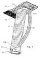
Fig. 3 is a view corresponding toFig. 2 of the first embodiment of the roof light system shown from the side intended to face inwards into a building; -
Fig. 4 is a view corresponding toFig. 3 of a second embodiment of the roof light system; -
Fig. 5 shows a perspective view of a detail of the roof light system shown inFig. 3 ; -
Fig. 6 shows a sectional view of the detail shown inFig. 5 ; -
Figs. 7 and8 show perspective views of a detail of the embodiment of the roof light system shown inFigs. 1-3 ; -
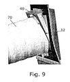
Fig. 9 shows a perspective view of the roof light system shown inFig. 3 during installation; -
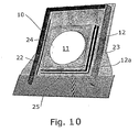
Fig. 10 is a partial perspective view of a detail of the roof light system; -
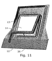
Fig. 11 is a view corresponding toFig. 10 of an alternative embodiment of the roof light system according to the present invention; -
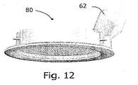
Fig. 12 shows a perspective view of a detail of the roof light system according to the invention; and -
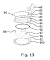
Fig. 13 is an exploded perspective view of the detail ofFig. 12 . - Referring to the drawings, the roof light system comprises a
roof unit 10, alight conduit 70 and adiffuser unit 80. These three components form a base module. - The
roof unit 10 is intended to be installed in the roof of a building and includes a light-admittingaperture 11 formed in aframe 12, cf.Fig. 10 . Light is admitted into theaperture 11 through asash 13 carrying aglazing 14, cf. in particularFigs. 2 and6 . Theglazing 14 may be formed in any suitable manner and from any suitable translucent material, e.g. glass or a plastic material.Roof unit 10 furthermore comprises a flashing arrangement intended to provide a substantially weather-tight transition to the surrounding roofing (not shown). In the embodiment shown, theframe 12 is formed integrally with substantially sheet-shapedportion 15 surrounding theframe 12 and is, in the mounted position, placed beneath the roofing. In order to direct precipitation on to askirt portion 17 placed on top of the roofing, rails 16 are provided on either side of theframe 12. Furthermore, a sealingstrip 18 is connected with the sheet-shapedportion 15 and theskirt portion 17 to prevent water from entering the underlying roof structure. The flashing arrangement may also be provided separately from the frame and sash, or be dispensed with altogether, if the installation conditions allow so. - Opposite the
aperture 11 in theframe 12 ofroof unit 10, one end of thelight conduit 70 is connected with theframe 12 in a manner which will be described in detail further on. Thelight conduit 70 has a first cross-section and a first length which corresponds to or exceeds the distance between theroof unit 10 and thediffuser unit 80. The other end of thelight conduit 70 is connected with thediffuser unit 80, likewise to be described in detail further on. Thediffuser unit 80 is intended to be installed in the ceiling of an inner room in the building, andlight conduit 70 thus extends through at least the roof structure of the building. In the embodiment shown,light conduit 70 is formed as a length of flexible hose reinforced bywire hoops 71. However, the light conduit may be formed by rigid sections connected with each other to form the desired path of the light conduit between the roof unit and the diffuser unit. In order to ensure that as much natural lighting as possible is channelled from the outside to the inner room, the internal side of the light conduit is usually provided with a light reflective lining or coating, or the entire material of the light conduit is made from a light reflective material. - As mentioned in the above, the roof light system is provided as a base module comprising roof unit, light conduit, diffuser. In the embodiments described with reference to
Figs. 1 to 9 , a ventilation device is provided as a supplement. In the embodiment shown inFigs. 10 and11 , the roof light system may be modified into a traditional openable window. Furthermore, other parts of the base module may be exchanged or supplemented. For instance, the light conduit may be customized for e.g. very long or complicated routing through the roof structure. - In a first and second embodiment, a ventilation device is provided for allowing moist air to escape from the inner room and fresh air from the outside to enter the room. The ventilation device is supplied either together with the base module, or is retailed as a separate optional kit of elements, and comprises a
ventilation tube 60, which may be formed from any suitable, preferably flexible, material and may have any cross-sectional shape. There may be more than one ventilation tube. Theventilation tube 60 has a second cross-section and a second length extending between afirst end 60a and asecond end 60b. As is the case with thelight conduit 70, the second length corresponds to or exceeds the distance between theroof unit 10 and thediffuser unit 80. In thefirst end 60a theventilation tube 60 is connected with theroof unit 10 and in thesecond end 60b with thediffuser unit 80. - As the
ventilation tube 60 is separate from thelight conduit 70 and the cross-section of theventilation tube 60 is detached from, i.e. does not overlap at any point, the cross-section of thelight conduit 70, the ventilation device may be installed independently of the other parts of the roof light system. It is furthermore noted that the respective cross-sections may vary over the length of the light conduit and the ventilation tube, respectively. The cross-sections may, as indicated in the drawings, be entirely different. The respective lengths and courses of thelight conduit 70 and theventilation tube 60 may vary as well, e.g. to adapt to installation conditions. - In
Fig. 4 , a second embodiment is shown. In addition to theventilation tube 60, the ventilation device comprises afirst branch tube 160 extending between a first end 160a and asecond end 160b and asecond branch tube 260 extending between a first end 260a and asecond end 260b. In the embodiment shown, the first end 260a is positioned between thefirst end 60a and thesecond end 60b of theventilation tube 60, i.e. thesecond branch tube 260 is branched off from theventilation tube 60a. It is of course conceivable to let thesecond branch tube 260 branch off from thefirst branch tube 160, or to position the branch-off site arbitrarily along theventilation tube 60 or thefirst branch tube 160. In the embodiment shown, the branch-off is situated virtually at thefirst end 60a of theventilation tube 60. An obvious manner of obtaining this configuration is to cut theventilation tube 60 and thebranch tubes mouth piece 61. - In order to support the natural draught in the
ventilation tube 60, means for providing mechanical ventilation may be present in the ventilation device. Such means are known per se and may e.g. include an electrically operated fan. The fan or fans may be positioned arbitrarily in the ventilation device, e.g. in the roof unit or at themouth piece ventilation tube 60. In this case, the fan may be provided with two or more inlet ends, possibly covered by knock-out plates, and one outlet end facing thefirst end 60a of theventilation tube 60. - Details regarding the connection between the
light conduit 70 and theventilation tube 60, and theroof unit 10 will be described with particular reference toFigs. 5 to 9 . - The respective shape and size of the
frame 12 and thesash 13 may be arbitrary and is traditionally chosen to match possible other roof penetrating structures, such as skylights and roof windows, installed in the roof. In the embodiments shown in the drawings, theframe 12 andsash 13 have a substantially square shape, but other shapes, such as a rectangular shape other than square, are conceivable as well. As a consequence of the square shape of theframe 12 andsash 13 in combination with the circular cross-section of thelight conduit 70 in the preferred embodiment, an area L2a exists between theaperture 11 and an inner circumference of theframe 12, the inner circumference extending substantially alonglines 24, cf.Fig. 10 , the function of which will be described in further detail in the following. Thisarea 12a provides for a transition between therectangular frame 12 and the circular light conduit in parallel with theglazing 14. Thearea 12a may be utilized for positioning solar cells, preferably connected to battery means, to provide energy for e.g. a screening arrangement in the form of a dimmer situated in the roof light system, or possibly even for controlling or operating a drive motor of an electrically operated fan. Such solar cells may of course also be positioned on other places of the roof unit. For instance, the glazing may be covered by solar cells, in particular in the section corresponding to thearea 12a of the frame, e.g. on the inner side of the glazing. Thearea 12a may have a coloured and/or reflective film or coating in order to obtain a uniform appearance of the roof unit. Such film or coating may also be provided on theglazing 14. - One particularly advantageous manner of installing the roof light system according to the present invention comprises the following steps:
- The
roof unit 10 is mounted in an aperture in the roof prepared to that purpose. Attachment of the roof unit may be performed in any suitable manners known per se from skylights, roof windows and other roof penetrating structures, comprising e.g. the use of mounting brackets secured to the underlying roof structure in the form of rafters and laths, or sheathing. Roofing is placed on top of the sheet-shapedportion 15 of the flashing arrangement up to a suitable distance from theframe 12 andsash 13 of the roof unit, and theskirt portion 17 is made to abut against the upper face of the roofing below theframe 12 andsash 13. - Referring now to
Figs. 5 and6 , aring 30 is provided for connection with arim 19 surrounding theaperture 11 in theframe 12. In the vicinity of one edge of thering 30, a plurality ofpins 31 are distributed over the circumference of the ring for engagement withlugs 20 on therim 19. By positioning thepins 31 in front of a keyhole-shapedtrack 21 in eachlug 20 and then rotating thering 30 slightly, a safe engagement between thering 30 and theframe 12 is obtained. Subsequently, thelight conduit 70 is attached to thering 30 by first guiding one end oflight conduit 70 past acircumferential flange 32 at the other edge of thering 30, and then secure thelight conduit 70 to thering 30 and thus in turn to theframe 12 by means of a draw-band (not shown) positioned above theflange 32. It is noted that the ring may be made integral with the frame, or dispensed with altogether, the connection thus being carried out in any suitable manner. The light conduit thus extends substantially perpendicularly to and almost up to theglazing 14 near theroof unit 10. This provides for an optimum influx of light. A small spacing between the light conduit, or in this case the ring, is left up to the glazing in order to avoid condensation. - When the
light conduit 70 has thus been connected with theroof unit 10, amanifold member 40 shown in detail in Figs. 75 and8 is connected with theroof unit 10. Themanifold member 40 is mainly U-shaped and at the ends oflegs 41, engagement means in the form of protrudingflaps 42 are provided. Theseflaps 42 are inserted into corresponding apertures in theframe 12. In the embodiment shown, these openings are provided by detaching two knock-outplates 22 at the bottom of theframe 12, cf.Fig. 10 , from the remaining portion of theframe 12 by an appropriate tool. The position shown inFig. 9 has now been attained.Manifold member 40 is then swung around flaps 42 at the end oflegs 41 until the bottom of the U-shape is brought into abutment with the under side of the upper part of theframe 12. Appropriate fastening means, such as screws, are then inserted throughupstanding reception elements 45 and further into theframe 12, cf.Fig. 8 . Themanifold member 40 may be connected with the frame in other ways than that described in the above, including screw fastening, fastening by adhesion, interlocking elements, snap connection etc. - The
manifold member 40 could have one of a variety of designs. One possibility is to form the manifold member integral with theframe 12. In its simplest form, the manifold member is constituted by a socket piece connected with the roof unit. The socket piece may e.g. be provided with knock-out plates which are detached when the ventilation device is to be installed. The manifold member may also provide for connection of more than one mouth piece, e.g. one mouth piece for each of the ventilation tube and the branch tube or tubes. Mouth pieces having one opening in the end facing the manifold member and two or more openings in the opposite end are also conceivable, i.e. one opening for each of the ventilation tube and the branch tube or tubes. The openings not in use may be covered by knock-out plates. - The
ventilation tube 60 is then connected with themanifold member 40 by means of itsmouth piece 61. This connection is not shown in detail but may be carried out in any suitable manner, e.g. by snap engagement or screws. The position shown inFig. 3 is now attained. - Ventilation of the inner room is performed by means of the following features in the
manifold member 40 and the roof unit 10: At the bottom of the U-shape ofmanifold member 40, a series of arc-shapedopenings 43 surrounded bywalls 44c is provided. Air flowing to or from theventilation tube 60 is allowed to pass through theseopenings 43. Themanifold member 40 is in fluid communication with the outside by means of a plurality of apertures in theframe 12. As is the case with the flap receiving apertures, such apertures may be obtained by detaching knock-outplates 23 in theframe 12 from the remaining part of the frame, cf.Figs. 6 and10 . In the installed condition of the roof light system, thesash 13 and theframe 12 form a kind of labyrinth seal, which allows air to escape from and enter into the ventilation tube, but which at the same time makes it difficult for precipitation to enter into the manifold and possibly the ventilation tube. In case precipitation nevertheless enters themanifold member 40, or in case condensation is formed, a controlled drainage is provided, as water collected in the trough defined byouter walls upstanding walls 44b surrounding openings 43 may flow out of theframe 12 through the apertures receiving flaps 42.Upstanding wall sections 44b prevent flow of water into theventilation tube 60.Upstanding wall sections 46 form a labyrinth seal in order to secure that precipitation that might have entered themanifold member 40 through these apertures does not flow in the opposite direction. - In case it is desirable to modify the roof light system into a traditional openable window, the following steps are carried out, with reference in particular to
Figs. 10 and11 . -
Light conduit 70 is removed substantially in reverse manner in relation to the installation operation as described in the above. -
Sash 13 is removed from theframe 12. In the state of delivery of the roof light system, thesash 13 is advantageously connected with theframe 12 by means of a hinge connection at the top of the sash L3 andframe 12. When the roof light system is in use, thesash 13 is most often secured to the frame by means of screws or similar fastening means to prevent thesash 13 from being opened inadvertently. Hinge connection may, however, be provided separately. - The
area 12a surrounding theaperture 11 in theframe 12 is detached from the remaining part of theframe 12. The detachment is facilitated by detachment indication lines 24. Detachment indication lines 24 may be provided by means of visual indication only, or as weakening lines. - An aperture at the bottom of the
frame 12 is obtained by means of a knock-out plate 25, the function of which is apparent fromFig. 11 , viz. to accommodate the passage of an extending device or astay 26. -
Sash 13 is re-connected with theframe 12, possibly after the application of a hinge connection, and the extendingdevice 26 is attached to thesash 13 and cooperating fixture means to theframe 12. Such extending devices, fixtures and other kinds of operating devices, e.g. an electrically operated chain, are known per se and are not the subject of detailed description. It is of course conceivable to let the interchangeable elements of the invention comprise elements suitable for substitution of parts of or the entire sash. For instance, it is possible to exchange thesash 13 of the base module with any other kind of sash, e.g. a sash having a different glazing with respect to colour, translucency or shape. For instance, the glazing may be substantially dome-shaped. - The
diffuser unit 80 depends from the light conduit of the roof light system described above, and transmits light received from the light conduit into the interior of the building room. The diffuser unit may take many different forms and is as such not a central part of the present invention. In the following an embodiment of the diffuser unit corresponding to the embodiment ofFig. 3 will be described. - The diffuser unit includes a ceiling ring, a dual diffuser, a trim ring, a ceiling ring gasket, and a diffuser gasket.
- With reference to
Figs. 12 and13 ,diffuser unit 80 is depicted.Ceiling ring 82 includes a plurality offlanges 84 configured for receipt of the light conduit from the roof light system. As will be appreciated,flanges 84 are configured for mating attachment with the distal end of the light conduit, whether the light conduit is constructed of a flexible tube or of a solid member. The light conduit may be attached to theflanges 84 by screws, banding attachment, or the like. - It will be observed in
Fig. 13 that gasket 99 is also provided.Gasket 99 is disposed for receipt aboveflange 83 ofceiling ring 82, to provide a seal betweenflange 83 and gypsum, sheetrock, or like ceiling material upon installation of the diffuser unit in a building. -
Ceiling ring 82 also includes a plurality of adjustable mountingcams 86. Mountingcams 86 are activated byscrews 88, the heads of which are accessible from beneathceiling ring 82. By turningscrews 88, mountingcams 86 are drawn downward, with the gypsum boards, sheetrock, or like material by which the interior room ceiling is constructed disposed between mountingcams 86 andflange 83, thereby attachingceiling ring 82 to the ceiling. - Each
screw 88 also includes at its head a mounting tab (not shown in detail). Mounting tabs are configured to swing about the head ofscrews 88 to allow for receipt and attachment of thediffuser unit 92. - As depicted in
Fig. 13 ,diffuser unit 80 includesflange 83 about the exterior.Flange 83 is configured for co-planar disposition against the interior ceiling of a building. As noted inFig. 13 ,flange 83 also includes a plurality of apertures 94. Apertures 94 are configured for receipt of theventilation tube 60 of the roof light system, if the roof light system is supplemented with a ventilation device as in the embodiment ofFigs. 1 to 8 . The apertures 94 are advantageously provided by detaching knock-out plates, as has been described in further detail with respect to other parts of the roof light system. In case no ventilation device is desired, these knock-out plates are left in place. In case a ventilation device is desired,mouth piece 62, which constitutes a manifold member having at least one opening to form a fluid communication with theventilation tube 60, is connected with thediffuser unit 80 in any suitable manner. It will be appreciated that, by engagement of such a ventilation tube with apertures 94 uponceiling ring 82, only a single penetration of an interior building ceiling would be necessary for installation of both a roof light system as well as a roof ventilation system. -
Diffuser unit 80 also includesdiffuser pan 96 anddiffuser 92.Diffuser pan 96 is configured to slide within the interior opening defined withinceiling ring 82. Likewise,diffuser 92 is configured for fitting within the aperture defined withinceiling ring 82.Diffuser pan 96 receivesdiffuser 92 so as to allow a space of air betweendiffuser 92 and thepane 97 ofdiffuser pan 96. So disposed, the combination ofdiffuser pan 96 anddiffuser 92 creates a thermal barrier to the transmission of heat to or from the roof light system. Oncediffuser pan 96 anddiffuser pan 92 are installed within the aperture defined through the center ofceiling ring 82, mounting tabs 90 are swung into position to holddiffuser 92, and thus alsodiffuser pan 96, withinceiling ring 82, blocking their removal. Disposed abovediffuser pan 96 isgasket 98, providing a seal of the roof light system against the intrusion of humidity, dust, and insects to the interior of the roof light system. - Finally provided is
trim ring 100, adapted for a snap fit engagement withceiling ring 82.Trim ring 100 provides a finished outward surface fordiffuser unit 80 upon installation ofdiffuser unit 80 into a ceiling. - So configured, installation of
diffuser unit 80 into a building may proceed as follows. Upon installation of a roof unit in accordance with the present invention, an aperture may be cut through a ceiling of a building of appropriate size for receipt ofdiffuser unit 80. Withgasket 99 in place aboutceiling ring 82 aboveflange 83,ceiling ring 82 andgasket 99 may be inserted through such hole. So inserted, screws 88 are then turned so as to engage mountingcams 86, so as to capture between mountingcams 86 andflange 83 the ceiling gypsum board, sheetrock, or the like, thereby attachingceiling ring 82 into the ceiling. The light conduit may then be attached to flanges 84. In the embodiment shown inFigs. 12 and13 , theventilation tube 60 is attached to apertures 94 by means ofmouth piece 62 constituting a manifold member as described in the above.Gasket 98 may then be installed within the aperture defined withinceiling ring 82. Withgasket 98 in place,diffuser pan 96 anddiffuser 92 may be installed within the aperture ofceiling ring 82, with mounting tabs then turned to holddiffuser 92 withinceiling ring 82 against gravity. Thetrim ring 100 may then be installed over the exposedflange 83 ofceiling ring 82, snap fitted into place. - The invention should not be regarded as being limited to the embodiments shown and described in the above. Various modifications and combinations may be carried out without departing from the scope of the appended claims.
Claims (20)
- Roof light system comprising a base module including a roof unit (10), a light conduit (70) and a diffuser unit (80), said light conduit extending between a first end positioned at the roof unit and a second end positioned at the diffuser unit, characterized in that, the roof unit (10) comprises a frame (12) defining an inner circumference and having a circular aperture (11) and a sash (13) carrying a glazing (14), said frame and sash having a rectangular shape, said light conduit (70) having a circular shape, and said first end of the light conduit being detachably connected with the frame (12) at said circular aperture (11), the area between the inner circumference of the frame (12) and the circular aperture (11) constituting a transition area (12a) substantially in parallel with the glazing, the roof light system furthermore comprising optional elements adapted to be connected with the base module, and interchangeable elements to replace elements of at least the roof unit and the light conduit of the base module.
- A roof light system according to claim 1, wherein the shape of the frame (12) and the sash (13) is square.
- A roof light system according to claim 2, wherein a ring (30) is provided for connection with a rim (19) surrounding said aperture (11), said ring being provided with pins (31) for engagement with lugs (20) on the rim.
- A roof light system according to claim 3, wherein said ring (30) is provided with a circumferential flange (32), said light conduit being connected with the ring by means of a draw-band positioned above said flange.
- Roof light system according to any one of the preceding claims, wherein said optional elements comprise a ventilation device including a ventilation tube (60) extending between a first end (60a) and a second end (60b), said first end being connected with the roof unit at said transition area (12a).
- Roof light system according to claim 5, wherein said ventilation tube (60) is separate from the light conduit (70), said second end (60b) of the ventilation tube being connected with the diffuser unit (80).
- A roof light system according to any one of claims 5 or 6, wherein the ventilation tube (60) is connected with the roof unit by means of a manifold member (40).
- A roof light system according to claim 7, wherein the manifold member (40) is a separate member connected with the frame (12).
- A roof light system according to claim 8, wherein the manifold member (40) is substantially U-shaped and surrounds the light conduit (70) partially.
- A roof light system according to any one of claims 7 to 9, wherein the second end of said ventilation tube (60) is connected with the diffuser unit (80) by means of a manifold member (62).
- A roof light system according to any one of claims 7 to 10, wherein the manifold member (40,62) is releasably connected with the roof unit or diffuser unit (10,80) by means of engagement means (42) on the manifold member cooperating with apertures (22,94) in the roof unit or diffuser unit, said apertures being preferably provided as knock-out plates (22) surrounded by detachment indication lines, and supplemental connection means (45) being preferably provided.
- A roof light system according to any one of claims 7 to 11, wherein said manifold member (40) comprises a series of openings (43) surrounded by upstanding walls (44b) .
- A roof light system according to any one of claims 5 to 12, wherein the ventilation device in addition to said ventilation tube (60) comprises at least one branch tube (160,260) extending between a first end (160a,260a) and a second end (160b,260b).
- A roof light system according to claim 13, wherein the second end (160b,260b) of the at least one branch tube (160,260) is positioned at a distance from the diffuser unit (80) .
- A roof light system according to any one of claims 5 to 14, wherein means for mechanical ventilation is provided.
- A roof light system according to claim 1, wherein said optional elements of the roof light system includes means for providing a hinge connection between the sash (L3) and the frame (12).
- A roof light system according to claim 16, wherein detachment indication lines (24) are provided at the inner circumference of the frame (12).
- A roof light system according to claim 17, wherein said frame (12) is provided with at least one knock-out plate (25) adapted to allow passage of an extending device (26).
- A roof light system according to any one of the preceding claims, wherein said optional elements include a plurality of solar cells provided on the roof unit.
- A roof light system according to any one of the preceding claims, wherein the roof unit (10) comprises a frame (12) and a sash (13) carrying a glazing (14), and wherein said optional elements include a reflective and/or coloured film or coating provided on the frame and/or on the glazing.
Priority Applications (1)
| Application Number | Priority Date | Filing Date | Title |
|---|---|---|---|
| PL05731861T PL1756482T3 (en) | 2004-04-19 | 2005-04-18 | Roof light system comprising optional elements and interchangeable parts |
Applications Claiming Priority (4)
| Application Number | Priority Date | Filing Date | Title |
|---|---|---|---|
| DKPA200400612 | 2004-04-19 | ||
| DKPA200400611 | 2004-04-19 | ||
| PCT/DK2005/000044 WO2005100872A1 (en) | 2004-04-19 | 2005-01-24 | Roof light system having an improved ventilation device |
| PCT/DK2005/000262 WO2005100871A1 (en) | 2004-04-19 | 2005-04-18 | Roof light system comprising optional elements and interchangeable parts |
Publications (2)
| Publication Number | Publication Date |
|---|---|
| EP1756482A1 EP1756482A1 (en) | 2007-02-28 |
| EP1756482B1 true EP1756482B1 (en) | 2008-07-30 |
Family
ID=34964220
Family Applications (1)
| Application Number | Title | Priority Date | Filing Date |
|---|---|---|---|
| EP05731861A Expired - Lifetime EP1756482B1 (en) | 2004-04-19 | 2005-04-18 | Roof light system comprising optional elements and interchangeable parts |
Country Status (7)
| Country | Link |
|---|---|
| EP (1) | EP1756482B1 (en) |
| AT (1) | ATE403118T1 (en) |
| DE (1) | DE602005008593D1 (en) |
| DK (1) | DK1756482T3 (en) |
| ES (1) | ES2311983T3 (en) |
| PL (1) | PL1756482T3 (en) |
| WO (1) | WO2005100871A1 (en) |
Cited By (3)
| Publication number | Priority date | Publication date | Assignee | Title |
|---|---|---|---|---|
| EP3789556A1 (en) | 2019-09-06 | 2021-03-10 | VKR Holding A/S | Roof light system comprising a roof module, a ceiling module and a shaft arrangement |
| EP3792423A1 (en) | 2019-09-06 | 2021-03-17 | VKR Holding A/S | Window module with improved lifting assembly, and roof light system comprising such a window module as a ceiling module |
| US11592197B2 (en) | 2018-09-28 | 2023-02-28 | Solatube International, Inc. | Bottom-mounted whole house fan assembly |
Families Citing this family (3)
| Publication number | Priority date | Publication date | Assignee | Title |
|---|---|---|---|---|
| CN101103160B (en) * | 2005-01-24 | 2010-09-29 | Vkr控股公司 | Rooflighting system with ventilation for improved flexibility |
| GB2425134A (en) * | 2005-04-14 | 2006-10-18 | Monodraught Ltd | Diffuser arrangement |
| DE102012016351A1 (en) * | 2012-08-16 | 2014-03-13 | Roto Frank Ag | Skylight arrangement |
Family Cites Families (3)
| Publication number | Priority date | Publication date | Assignee | Title |
|---|---|---|---|---|
| US4809468A (en) * | 1987-04-24 | 1989-03-07 | Bareiss Raymond E | Light transmitter interconnecting a skylight and a ceiling opening |
| FR2621940A1 (en) * | 1987-10-19 | 1989-04-21 | Siplast Sa | FLEXIBLE CONDUIT USEFUL FOR CONNECTING TWO OPENINGS AND ESPECIALLY FOR PIPING A BRIGHT FLOW FROM A LIGHT-CAPTURING OPENING TO A LIGHT-EMERGING OPENING AND A NATURAL LIGHTING SYSTEM OF A BUILDING PART USING SUCH A SOFT CONDUIT |
| US5613333A (en) * | 1994-09-16 | 1997-03-25 | Witzig, Jr.; Michael J. | Motorized skylight assembly for mounting on the roof of a building |
-
2005
- 2005-04-18 EP EP05731861A patent/EP1756482B1/en not_active Expired - Lifetime
- 2005-04-18 PL PL05731861T patent/PL1756482T3/en unknown
- 2005-04-18 ES ES05731861T patent/ES2311983T3/en not_active Expired - Lifetime
- 2005-04-18 DK DK05731861T patent/DK1756482T3/en active
- 2005-04-18 WO PCT/DK2005/000262 patent/WO2005100871A1/en not_active Ceased
- 2005-04-18 AT AT05731861T patent/ATE403118T1/en active
- 2005-04-18 DE DE602005008593T patent/DE602005008593D1/en not_active Expired - Lifetime
Cited By (5)
| Publication number | Priority date | Publication date | Assignee | Title |
|---|---|---|---|---|
| US11592197B2 (en) | 2018-09-28 | 2023-02-28 | Solatube International, Inc. | Bottom-mounted whole house fan assembly |
| EP3789556A1 (en) | 2019-09-06 | 2021-03-10 | VKR Holding A/S | Roof light system comprising a roof module, a ceiling module and a shaft arrangement |
| EP3789558A1 (en) | 2019-09-06 | 2021-03-10 | VKR Holding A/S | Light guiding system comprising a shaft arrangement, and method of providing such a shaft arrangement in a mounted condition |
| EP3789557A1 (en) | 2019-09-06 | 2021-03-10 | VKR Holding A/S | Kit for providing a roof light system comprising a roof module, a ceiling module and a shaft arrangement, and a method of installing a roof light system in a roof |
| EP3792423A1 (en) | 2019-09-06 | 2021-03-17 | VKR Holding A/S | Window module with improved lifting assembly, and roof light system comprising such a window module as a ceiling module |
Also Published As
| Publication number | Publication date |
|---|---|
| DK1756482T3 (en) | 2008-12-01 |
| PL1756482T3 (en) | 2009-01-30 |
| EP1756482A1 (en) | 2007-02-28 |
| ATE403118T1 (en) | 2008-08-15 |
| ES2311983T3 (en) | 2009-02-16 |
| WO2005100871A1 (en) | 2005-10-27 |
| DE602005008593D1 (en) | 2008-09-11 |
Similar Documents
| Publication | Publication Date | Title |
|---|---|---|
| US6142645A (en) | Skylight system | |
| US11834832B2 (en) | Roof window system with a ventilation unit mounted adjacent to the roof window, and a method of providing ventilation for a building | |
| US11993934B2 (en) | Roof window system with a ventilation unit mounted adjacent to the roof window, a roof structure including a roof window system, a method of providing a roof window system and a method of retrofitting a roof window system | |
| EP1756482B1 (en) | Roof light system comprising optional elements and interchangeable parts | |
| EP1841931B1 (en) | Roof light system having a ventilation device with improved flexibility | |
| US11788744B2 (en) | Ventilation systems | |
| US5613333A (en) | Motorized skylight assembly for mounting on the roof of a building | |
| EP1756481B1 (en) | Roof light system having an improved ventilation device | |
| US20050081462A1 (en) | Skylight kit and method | |
| US6431979B1 (en) | Wall curb for HVAC system | |
| JP3938009B2 (en) | Daylighting window structure | |
| KR200450750Y1 (en) | Duct frame fixing structure of air conditioner diffuser | |
| CA2405534C (en) | Roof vent | |
| US6786815B1 (en) | Apparatus for venting rooms with exhaust fans | |
| JP3037375U (en) | Ventilator and ventilation port mounting parts | |
| JPH0736055Y2 (en) | Bay window structure | |
| JP2005299970A (en) | Shutter device | |
| JPH09184262A (en) | Ridge ventilation device | |
| JPH0611149A (en) | Air conditioner | |
| JPH0821048A (en) | Skylight device |
Legal Events
| Date | Code | Title | Description |
|---|---|---|---|
| PUAI | Public reference made under article 153(3) epc to a published international application that has entered the european phase |
Free format text: ORIGINAL CODE: 0009012 |
|
| 17P | Request for examination filed |
Effective date: 20061103 |
|
| AK | Designated contracting states |
Kind code of ref document: A1 Designated state(s): AT BE BG CH CY CZ DE DK EE ES FI FR GB GR HU IE IS IT LI LT LU MC NL PL PT RO SE SI SK TR |
|
| RIN1 | Information on inventor provided before grant (corrected) |
Inventor name: LARSEN, NIELS, A. Inventor name: BRINTON, JAMES, ERIC Inventor name: JACOBSEN, PER Inventor name: MOLLER, BRENT Inventor name: MOODY, LEONARD, KENNETH, JR. |
|
| DAX | Request for extension of the european patent (deleted) | ||
| RAP1 | Party data changed (applicant data changed or rights of an application transferred) |
Owner name: VKR HOLDING A/S |
|
| GRAP | Despatch of communication of intention to grant a patent |
Free format text: ORIGINAL CODE: EPIDOSNIGR1 |
|
| GRAS | Grant fee paid |
Free format text: ORIGINAL CODE: EPIDOSNIGR3 |
|
| GRAA | (expected) grant |
Free format text: ORIGINAL CODE: 0009210 |
|
| RIN1 | Information on inventor provided before grant (corrected) |
Inventor name: BRINTON, JAMES, ERIC Inventor name: LARSEN, NIELS, A. Inventor name: MOODY, LEONARD, KENNETH, JR. Inventor name: MOLLER, BRENT Inventor name: JACOBSEN, PER |
|
| AK | Designated contracting states |
Kind code of ref document: B1 Designated state(s): AT BE BG CH CY CZ DE DK EE ES FI FR GB GR HU IE IS IT LI LT LU MC NL PL PT RO SE SI SK TR |
|
| REG | Reference to a national code |
Ref country code: GB Ref legal event code: FG4D |
|
| REG | Reference to a national code |
Ref country code: CH Ref legal event code: EP |
|
| REF | Corresponds to: |
Ref document number: 602005008593 Country of ref document: DE Date of ref document: 20080911 Kind code of ref document: P |
|
| REG | Reference to a national code |
Ref country code: IE Ref legal event code: FG4D |
|
| REG | Reference to a national code |
Ref country code: DK Ref legal event code: T3 |
|
| PG25 | Lapsed in a contracting state [announced via postgrant information from national office to epo] |
Ref country code: IS Free format text: LAPSE BECAUSE OF FAILURE TO SUBMIT A TRANSLATION OF THE DESCRIPTION OR TO PAY THE FEE WITHIN THE PRESCRIBED TIME-LIMIT Effective date: 20081130 Ref country code: LT Free format text: LAPSE BECAUSE OF FAILURE TO SUBMIT A TRANSLATION OF THE DESCRIPTION OR TO PAY THE FEE WITHIN THE PRESCRIBED TIME-LIMIT Effective date: 20080730 Ref country code: NL Free format text: LAPSE BECAUSE OF FAILURE TO SUBMIT A TRANSLATION OF THE DESCRIPTION OR TO PAY THE FEE WITHIN THE PRESCRIBED TIME-LIMIT Effective date: 20080730 |
|
| REG | Reference to a national code |
Ref country code: PL Ref legal event code: T3 |
|
| REG | Reference to a national code |
Ref country code: ES Ref legal event code: FG2A Ref document number: 2311983 Country of ref document: ES Kind code of ref document: T3 |
|
| PG25 | Lapsed in a contracting state [announced via postgrant information from national office to epo] |
Ref country code: PT Free format text: LAPSE BECAUSE OF FAILURE TO SUBMIT A TRANSLATION OF THE DESCRIPTION OR TO PAY THE FEE WITHIN THE PRESCRIBED TIME-LIMIT Effective date: 20081230 Ref country code: SI Free format text: LAPSE BECAUSE OF FAILURE TO SUBMIT A TRANSLATION OF THE DESCRIPTION OR TO PAY THE FEE WITHIN THE PRESCRIBED TIME-LIMIT Effective date: 20080730 Ref country code: BG Free format text: LAPSE BECAUSE OF FAILURE TO SUBMIT A TRANSLATION OF THE DESCRIPTION OR TO PAY THE FEE WITHIN THE PRESCRIBED TIME-LIMIT Effective date: 20081030 Ref country code: FI Free format text: LAPSE BECAUSE OF FAILURE TO SUBMIT A TRANSLATION OF THE DESCRIPTION OR TO PAY THE FEE WITHIN THE PRESCRIBED TIME-LIMIT Effective date: 20080730 |
|
| PG25 | Lapsed in a contracting state [announced via postgrant information from national office to epo] |
Ref country code: BE Free format text: LAPSE BECAUSE OF FAILURE TO SUBMIT A TRANSLATION OF THE DESCRIPTION OR TO PAY THE FEE WITHIN THE PRESCRIBED TIME-LIMIT Effective date: 20080730 |
|
| PG25 | Lapsed in a contracting state [announced via postgrant information from national office to epo] |
Ref country code: EE Free format text: LAPSE BECAUSE OF FAILURE TO SUBMIT A TRANSLATION OF THE DESCRIPTION OR TO PAY THE FEE WITHIN THE PRESCRIBED TIME-LIMIT Effective date: 20080730 |
|
| PG25 | Lapsed in a contracting state [announced via postgrant information from national office to epo] |
Ref country code: CZ Free format text: LAPSE BECAUSE OF FAILURE TO SUBMIT A TRANSLATION OF THE DESCRIPTION OR TO PAY THE FEE WITHIN THE PRESCRIBED TIME-LIMIT Effective date: 20080730 Ref country code: SK Free format text: LAPSE BECAUSE OF FAILURE TO SUBMIT A TRANSLATION OF THE DESCRIPTION OR TO PAY THE FEE WITHIN THE PRESCRIBED TIME-LIMIT Effective date: 20080730 Ref country code: RO Free format text: LAPSE BECAUSE OF FAILURE TO SUBMIT A TRANSLATION OF THE DESCRIPTION OR TO PAY THE FEE WITHIN THE PRESCRIBED TIME-LIMIT Effective date: 20080730 |
|
| PLBE | No opposition filed within time limit |
Free format text: ORIGINAL CODE: 0009261 |
|
| STAA | Information on the status of an ep patent application or granted ep patent |
Free format text: STATUS: NO OPPOSITION FILED WITHIN TIME LIMIT |
|
| 26N | No opposition filed |
Effective date: 20090506 |
|
| REG | Reference to a national code |
Ref country code: CH Ref legal event code: PL |
|
| PG25 | Lapsed in a contracting state [announced via postgrant information from national office to epo] |
Ref country code: LI Free format text: LAPSE BECAUSE OF NON-PAYMENT OF DUE FEES Effective date: 20090430 Ref country code: SE Free format text: LAPSE BECAUSE OF FAILURE TO SUBMIT A TRANSLATION OF THE DESCRIPTION OR TO PAY THE FEE WITHIN THE PRESCRIBED TIME-LIMIT Effective date: 20081030 Ref country code: CH Free format text: LAPSE BECAUSE OF NON-PAYMENT OF DUE FEES Effective date: 20090430 |
|
| PG25 | Lapsed in a contracting state [announced via postgrant information from national office to epo] |
Ref country code: MC Free format text: LAPSE BECAUSE OF NON-PAYMENT OF DUE FEES Effective date: 20090430 Ref country code: IE Free format text: LAPSE BECAUSE OF NON-PAYMENT OF DUE FEES Effective date: 20090418 |
|
| PG25 | Lapsed in a contracting state [announced via postgrant information from national office to epo] |
Ref country code: GR Free format text: LAPSE BECAUSE OF FAILURE TO SUBMIT A TRANSLATION OF THE DESCRIPTION OR TO PAY THE FEE WITHIN THE PRESCRIBED TIME-LIMIT Effective date: 20081031 |
|
| PG25 | Lapsed in a contracting state [announced via postgrant information from national office to epo] |
Ref country code: LU Free format text: LAPSE BECAUSE OF NON-PAYMENT OF DUE FEES Effective date: 20090418 |
|
| PG25 | Lapsed in a contracting state [announced via postgrant information from national office to epo] |
Ref country code: HU Free format text: LAPSE BECAUSE OF FAILURE TO SUBMIT A TRANSLATION OF THE DESCRIPTION OR TO PAY THE FEE WITHIN THE PRESCRIBED TIME-LIMIT Effective date: 20090131 |
|
| PG25 | Lapsed in a contracting state [announced via postgrant information from national office to epo] |
Ref country code: TR Free format text: LAPSE BECAUSE OF FAILURE TO SUBMIT A TRANSLATION OF THE DESCRIPTION OR TO PAY THE FEE WITHIN THE PRESCRIBED TIME-LIMIT Effective date: 20080730 |
|
| PG25 | Lapsed in a contracting state [announced via postgrant information from national office to epo] |
Ref country code: CY Free format text: LAPSE BECAUSE OF FAILURE TO SUBMIT A TRANSLATION OF THE DESCRIPTION OR TO PAY THE FEE WITHIN THE PRESCRIBED TIME-LIMIT Effective date: 20080730 |
|
| PGFP | Annual fee paid to national office [announced via postgrant information from national office to epo] |
Ref country code: AT Payment date: 20140326 Year of fee payment: 10 |
|
| PGFP | Annual fee paid to national office [announced via postgrant information from national office to epo] |
Ref country code: DK Payment date: 20140410 Year of fee payment: 10 |
|
| PGFP | Annual fee paid to national office [announced via postgrant information from national office to epo] |
Ref country code: ES Payment date: 20150310 Year of fee payment: 11 |
|
| PGFP | Annual fee paid to national office [announced via postgrant information from national office to epo] |
Ref country code: IT Payment date: 20150420 Year of fee payment: 11 |
|
| REG | Reference to a national code |
Ref country code: DK Ref legal event code: EBP Effective date: 20150430 |
|
| REG | Reference to a national code |
Ref country code: AT Ref legal event code: MM01 Ref document number: 403118 Country of ref document: AT Kind code of ref document: T Effective date: 20150418 |
|
| PG25 | Lapsed in a contracting state [announced via postgrant information from national office to epo] |
Ref country code: AT Free format text: LAPSE BECAUSE OF NON-PAYMENT OF DUE FEES Effective date: 20150418 |
|
| REG | Reference to a national code |
Ref country code: FR Ref legal event code: PLFP Year of fee payment: 12 |
|
| PG25 | Lapsed in a contracting state [announced via postgrant information from national office to epo] |
Ref country code: DK Free format text: LAPSE BECAUSE OF NON-PAYMENT OF DUE FEES Effective date: 20150430 |
|
| PG25 | Lapsed in a contracting state [announced via postgrant information from national office to epo] |
Ref country code: IT Free format text: LAPSE BECAUSE OF NON-PAYMENT OF DUE FEES Effective date: 20160418 |
|
| REG | Reference to a national code |
Ref country code: FR Ref legal event code: PLFP Year of fee payment: 13 |
|
| REG | Reference to a national code |
Ref country code: FR Ref legal event code: PLFP Year of fee payment: 14 |
|
| PG25 | Lapsed in a contracting state [announced via postgrant information from national office to epo] |
Ref country code: ES Free format text: LAPSE BECAUSE OF NON-PAYMENT OF DUE FEES Effective date: 20160419 |
|
| REG | Reference to a national code |
Ref country code: ES Ref legal event code: FD2A Effective date: 20181205 |
|
| PGFP | Annual fee paid to national office [announced via postgrant information from national office to epo] |
Ref country code: FR Payment date: 20190326 Year of fee payment: 15 Ref country code: PL Payment date: 20190320 Year of fee payment: 15 |
|
| PGFP | Annual fee paid to national office [announced via postgrant information from national office to epo] |
Ref country code: GB Payment date: 20190417 Year of fee payment: 15 |
|
| PG25 | Lapsed in a contracting state [announced via postgrant information from national office to epo] |
Ref country code: FR Free format text: LAPSE BECAUSE OF NON-PAYMENT OF DUE FEES Effective date: 20200430 |
|
| GBPC | Gb: european patent ceased through non-payment of renewal fee |
Effective date: 20200418 |
|
| PG25 | Lapsed in a contracting state [announced via postgrant information from national office to epo] |
Ref country code: GB Free format text: LAPSE BECAUSE OF NON-PAYMENT OF DUE FEES Effective date: 20200418 |
|
| PGFP | Annual fee paid to national office [announced via postgrant information from national office to epo] |
Ref country code: DE Payment date: 20210323 Year of fee payment: 17 |
|
| PG25 | Lapsed in a contracting state [announced via postgrant information from national office to epo] |
Ref country code: PL Free format text: LAPSE BECAUSE OF NON-PAYMENT OF DUE FEES Effective date: 20200418 |
|
| REG | Reference to a national code |
Ref country code: DE Ref legal event code: R119 Ref document number: 602005008593 Country of ref document: DE |
|
| PG25 | Lapsed in a contracting state [announced via postgrant information from national office to epo] |
Ref country code: DE Free format text: LAPSE BECAUSE OF NON-PAYMENT OF DUE FEES Effective date: 20221103 |