JP2005299970A - Shutter device - Google Patents

Shutter device Download PDF

Info

Publication number
JP2005299970A
JP2005299970A JP2004113817A JP2004113817A JP2005299970A JP 2005299970 A JP2005299970 A JP 2005299970A JP 2004113817 A JP2004113817 A JP 2004113817A JP 2004113817 A JP2004113817 A JP 2004113817A JP 2005299970 A JP2005299970 A JP 2005299970A
Authority
JP
Japan
Prior art keywords
adapter
duct
shutter
side cylinder
shutter device
Prior art date
Legal status (The legal status is an assumption and is not a legal conclusion. Google has not performed a legal analysis and makes no representation as to the accuracy of the status listed.)
Granted
Application number
JP2004113817A
Other languages
Japanese (ja)
Other versions
JP4396364B2 (en
Inventor
Yoshio Isori
良雄 五十里
Current Assignee (The listed assignees may be inaccurate. Google has not performed a legal analysis and makes no representation or warranty as to the accuracy of the list.)
Panasonic Holdings Corp
Original Assignee
Matsushita Electric Industrial Co Ltd
Priority date (The priority date is an assumption and is not a legal conclusion. Google has not performed a legal analysis and makes no representation as to the accuracy of the date listed.)
Filing date
Publication date
Application filed by Matsushita Electric Industrial Co Ltd filed Critical Matsushita Electric Industrial Co Ltd
Priority to JP2004113817A priority Critical patent/JP4396364B2/en
Publication of JP2005299970A publication Critical patent/JP2005299970A/en
Application granted granted Critical
Publication of JP4396364B2 publication Critical patent/JP4396364B2/en
Anticipated expiration legal-status Critical
Expired - Fee Related legal-status Critical Current

Links

Images

Landscapes

  • Air-Flow Control Members (AREA)

Abstract

<P>PROBLEM TO BE SOLVED: To provide a shutter device which can be directly attached to an adapter provided on a ventilator, and capable of reducing installation man-hours. <P>SOLUTION: In the shutter device, by providing a duct connection port 18 and an adapter connection port 16 on the electric shutter device 6, and directly connecting and fixing the electric shutter device 6 to the ventilator 2, the ventilator 2 and the electric shutter device 6 can be installed in adjacent portions, work of embedding the ventilator in an underpart of a roof, work of connecting and fixing the electric shutter device, and maintenance work can be carried out in the same place, and the installation man-hours can be reduced. <P>COPYRIGHT: (C)2006,JPO&NCIPI

Description

本発明は、空調機、換気装置などの機器で屋外と連通するダクトからの外風などを強制的に遮断するために用いるシャッター装置に関するものである。   The present invention relates to a shutter device that is used for forcibly blocking outside air from a duct communicating with the outdoors in an apparatus such as an air conditioner or a ventilator.

従来、この種のシャッター装置として、その構造面を示すものとしては一体に形成された円筒内の中間部分にダンパー(シャッター)を回転自在に備えたダクト用ダンパが知られている(例えば、特許文献1参照)。   Conventionally, as this type of shutter device, a damper for a duct having a damper (shutter) rotatably provided at an intermediate portion in an integrally formed cylinder has been known as an example of the structural surface (for example, a patent) Reference 1).

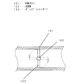
これは図4に示すように、一体に形成された円筒ダクト101内に回動するための支持部102を備えたダンパ(シャッター)103を配して構成され、ダンパ(シャッター)103を回動させて風路の開閉を行うものである。   As shown in FIG. 4, a damper (shutter) 103 having a support portion 102 for rotating is arranged in an integrally formed cylindrical duct 101, and the damper (shutter) 103 is rotated. The air path is opened and closed.

また、この種のシャッター装置として、その本体の設置状況を示すものとしては、室内側または屋外側に連通するダクトと換気装置側に連通するダクトとの間に設置することを特徴とするものが知られている。(例えば、特許文献2参照)。   Further, as this kind of shutter device, the one indicating the installation state of the main body is characterized in that it is installed between a duct communicating with the indoor side or the outdoor side and a duct communicating with the ventilation device side. Are known. (For example, refer to Patent Document 2).

以下、そのシャッター装置について図5を参照しながら説明する。   The shutter device will be described below with reference to FIG.

図に示すように、建物の天井裏104に設けられ、天面部または側面部にダクト105と接続されるアダプター106を設けた箱体と、この箱体の内部に送風機を備えた換気装置107で、前記アダプターと室内108に連通させるダクト105があり、前記換気装置と室内を連通させる前記ダクト105の中間に接続されることを特徴とするシャッター装置109であった。
実開平3−23739号公報 特開昭61−191823号公報
As shown in the figure, a box body provided on the ceiling 104 of the building and provided with an adapter 106 connected to the duct 105 on the top surface or side surface portion, and a ventilation device 107 provided with a blower inside the box body. The shutter device 109 is characterized in that there is a duct 105 that communicates with the adapter and the room 108 and that is connected between the ventilation device and the duct 105 that communicates with the room.
Japanese Utility Model Publication No. 3-23739 JP 61-191823 A

しかしながら、構造面での従来の構成ではダンパー(シャッター)の組み付けに時間がかかったり、メンテナンス等で完成品を分解することが困難であった。   However, in the conventional structure in terms of structure, it takes time to assemble the damper (shutter), and it is difficult to disassemble the finished product for maintenance or the like.

本発明は、上記従来の課題を解決するもの、単純な構成とし組立てを容易にするとともに、組み付けて完成したものを、メンテナンス修理等の理由で分解する場合でも、簡単に分解することができるシャッター装置を提供することを目的とする。   The present invention solves the above-described conventional problems, has a simple structure, facilitates assembly, and can be easily disassembled even when disassembled for maintenance repair or the like. An object is to provide an apparatus.

また、設置面での従来の構成では、シャッター装置を設置するのに屋外側のダクトと換気装置側のダクト中継で設置しなければならないため、ダクトを少なくとも2本以上使用しなければならない。また、設置場所が換気装置とシャッター装置で異なり、各々の施工作業及びメンテナンスの作業場所が違うため作業工数が増えてしまうという課題があった。   Further, in the conventional configuration in terms of installation, it is necessary to install at least two ducts because it is necessary to install the shutter device by a duct on the outdoor side and a duct relay on the ventilation device side. In addition, the installation location is different between the ventilation device and the shutter device, and there is a problem that the number of work steps increases because the work location of each construction work and maintenance is different.

また、ダクトを介してアダプターと電動シャッターを接続するのでダクトを固定するための余分な吊りバンドが必要となるという課題があった。   Further, since the adapter and the electric shutter are connected via the duct, there is a problem that an extra hanging band for fixing the duct is required.

本発明は、前記従来の課題を解決するもので、換気装置とシャッター装置を設置する際のダクト接続本数や吊りバンドの数を減らし、施工性を向上するとともに施工作業場所を減らすことができるシャッター装置を提供することを目的とする。   The present invention solves the above-mentioned conventional problems, and reduces the number of duct connections and the number of suspension bands when installing a ventilation device and a shutter device, improving the workability and reducing the construction work place. An object is to provide an apparatus.

従来の課題を解決するために本発明のシャッター装置は、アダプター側筒体とダクト側筒体とシャッターから成り、アダプター側筒体またはダクト側筒体にシャッターを回動可能に保持する保持部を設け、この保持部にシャッターを保持した後、前記アダプター側筒体とダクト側筒体を係合させ合体組立てするシャッター装置において、アダプター側筒体とダクト側筒体の材質を樹脂とし相互の合体組立ては差込みの方法、分解する際は引き抜きの方法としたシャッター装置、としたものである。   In order to solve the conventional problems, the shutter device of the present invention includes an adapter-side cylinder, a duct-side cylinder, and a shutter, and a holding portion that rotatably holds the shutter on the adapter-side cylinder or the duct-side cylinder. In the shutter device that is provided and holds the shutter in the holding part and then engages and assembles the adapter-side cylinder and the duct-side cylinder, the adapter-side cylinder and the duct-side cylinder are made of resin as a combination. Assembling is a method of insertion, and when disassembling, a shutter device is used.

すなわち、筒体をアダプター側とダクト側に分けることで、その間に配置するシャッターの組み付けが容易で精度良く組立てできるようになる。   That is, by dividing the cylinder into the adapter side and the duct side, the shutter disposed between them can be easily assembled with high accuracy.

また、2つの筒体の組み付けは差し込んで行うので、やり易く、単純な作業なので品質が安定し、且つ、組み付けた後の分解は、逆の作業としての引き抜きなので、これも簡単な作業となるものである。   Also, the assembly of the two cylinders is done by inserting, so it is easy to do and the quality is stable because it is a simple operation, and the disassembly after assembly is pulled out as the reverse operation, so this is also an easy task Is.

また、従来の課題を解決するために本発明のシャッター装置は、アダプターにダクトを接続して換気をする換気装置の該アダプターに直接装着することを特徴とするシャッター装置、としたものである。   In order to solve the conventional problems, the shutter device of the present invention is a shutter device that is directly attached to an adapter of a ventilator that ventilates by connecting a duct to the adapter.

この手段により、シャッター装置と換気装置が近接することになり、取付作業やメンテナンス作業をする場合に、同時に、且つ、同位置で作業が可能となり作業効率が大幅に向上することとなる。   By this means, the shutter device and the ventilation device come close to each other, and when performing an installation operation or a maintenance operation, the operation can be performed at the same position at the same time, and the work efficiency is greatly improved.

また、シャッター装置と換気装置間の接続ダクトは不要となるとともに、そのダクトを固定するための吊りバンドも不要となり、部品点数が減って、当然、その取付作業等も不要となるものである。   In addition, a connecting duct between the shutter device and the ventilation device is not necessary, and a suspension band for fixing the duct is also unnecessary, the number of parts is reduced, and naturally, an installation operation and the like are also unnecessary.

また、一方側は換気装置に設けられた前記アダプターが内挿されて接続され、他方側はダクトが外挿されて接続され通風路を形成することを特徴とするシャッター装置、としたものである。   Also, the shutter device is characterized in that one side is connected with the adapter provided in the ventilation device inserted, and the other side is connected with a duct inserted by extrapolation to form a ventilation path. .

また、換気装置に設けられたアダプターが内挿され接続させる側の内周部に、前記アダプター先端部と当接させる段差を備える電動シャッター装置、としたものである。   Moreover, it is set as the electric shutter apparatus provided with the level | step difference made to contact | abut with the said adapter front-end | tip part in the inner peripheral part by which the adapter provided in the ventilation apparatus is inserted and connected.

また、換気装置を停止させたとき屋外と換気装置を連通させるダクトから侵入する外風を強制的に遮断させるシャッターの形状が円形状になっていることを特徴とする電動シャッター装置、としたものである。   Also, an electric shutter device characterized by a circular shutter shape that forcibly blocks outside air entering from the duct that communicates the outdoors with the ventilator when the ventilator is stopped It is.

また、シャッターの開閉軸が、ダクト接続口を正面視したときにシャッターを略均等に2分割することを特徴とする電動シャッター装置、としたものである。   Further, the shutter has an opening / closing shaft that divides the shutter substantially equally into two when the duct connection port is viewed from the front.

また、アダプターが内挿される部分とダクトが外挿される部分に分割可能な構成とした電動シャッター装置、としたものである。   In addition, the electric shutter device can be divided into a portion where the adapter is inserted and a portion where the duct is externally inserted.

また、アダプターに接続する接続口を備える構成部品にシャッター軸を保持する切り欠き部を備え、前記シャッター軸が回動自在に接触する前記切り欠き部の内縁を山形状にした電動シャッター装置、としたものである。   An electric shutter device comprising a cutout portion for holding a shutter shaft in a component having a connection port connected to an adapter, and an inner edge of the cutout portion in which the shutter shaft is rotatably contacted, and a mountain shape It is a thing.

本発明の電動シャッター装置によれば、換気装置が備えるアダプターに直接に接続できることにより、接続ダクト本数をすくなくとも1本削減でき、換気装置と電動シャッター装置の設置作業を同じ場所で行え、施工作業の削減になる。   According to the electric shutter device of the present invention, since it can be directly connected to the adapter provided in the ventilator, the number of connecting ducts can be reduced by at least one, and the installation work of the ventilator and the electric shutter device can be performed at the same place. Reduction.

本発明の請求項1記載の発明は、アダプター側筒体とダクト側筒体とシャッターから成り、アダプター側筒体またはダクト側筒体にシャッターを回動可能に保持する保持部を設け、この保持部にシャッターを保持した後、前記アダプター側筒体とダクト側筒体を係合させ合体組立てすることを特徴とするシャッター装置、としたものであり、筒体をアダプター側とダクト側の2つに分けることで、その間に配するシャッターを容易に、うまく精度良く組み付けられる。   The invention according to claim 1 of the present invention includes an adapter-side cylinder, a duct-side cylinder, and a shutter, and the adapter-side cylinder or the duct-side cylinder is provided with a holding portion that rotatably holds the shutter. After the shutter is held in the part, the adapter side cylinder and the duct side cylinder are engaged and assembled and assembled, and the cylinder is divided into two parts, the adapter side and the duct side. By dividing into two, the shutter placed between them can be assembled easily and accurately.

また、請求項2記載の発明は、アダプター側筒体とダクト側筒体とシャッターから成り、このシャッターにはこれを回動させるためのシャッター軸を設け、前記アダプター側筒体またはダクト側筒体には前記シャッター軸を回動可能に軸支する切り欠き部を設けるとともに、相互に差込み嵌合可能な嵌合部を設け、前記シャッター軸を前記切り欠き部に入れて軸支保持した後、前記アダプター側筒体とダクト側筒体を相互に差込み嵌合させて合体組立てすることを特徴とするシャッター装置、としたものであり、シャッターの組付けを、筒体に切り欠きを設けて、その切り欠きにシャッター軸を入れるだけの簡単な作業とするとともに、シャッターを組み付けた後、2つの筒体はを差込み嵌合させるだけで、シャッター装置の組み立が完成するものである。   The invention according to claim 2 comprises an adapter side cylinder, a duct side cylinder, and a shutter, and the shutter is provided with a shutter shaft for rotating the shutter, and the adapter side cylinder or the duct side cylinder is provided. In addition to providing a notch portion for pivotally supporting the shutter shaft, and providing a fitting portion that can be inserted and fitted to each other, after the shutter shaft is inserted into the notch portion and supported by the shaft, The adapter side cylinder and the duct side cylinder are inserted into each other and fitted to form a shutter device, and the shutter assembly is provided with a notch in the cylinder. The assembly of the shutter device is completed by simply inserting the two cylinders and fitting them together after assembling the shutter. It is intended.

また、請求項3記載の発明は、アダプター側筒体とダクト側筒体とシャッターから成り、アダプター側筒体またはダクト側筒体にシャッターを回動可能に保持する保持部を設け、この保持部にシャッターを保持した後、前記アダプター側筒体とダクト側筒体を係合させ合体組立てするシャッター装置において、アダプター側筒体とダクト側筒体の材質を樹脂とし相互の合体組立ての際は差込み方式、分解する際は引き抜き方式としたシャッター装置、としたものであり、2つの筒体は差込んで引き抜くことで、組立てや分解が簡単に行えることとなる。   The invention according to claim 3 includes an adapter-side cylinder, a duct-side cylinder, and a shutter, and the adapter-side cylinder or the duct-side cylinder is provided with a holding portion that rotatably holds the shutter. After the shutter is held in the shutter device, the adapter-side cylinder and the duct-side cylinder are engaged and assembled, and the adapter-side cylinder and the duct-side cylinder are made of resin. The system is a shutter device that is a pull-out type when disassembling, and the two cylinders can be inserted and pulled out so that assembly and disassembly can be performed easily.

また、請求項4記載の発明は、アダプター側筒体とダクト側筒体とシャッターから成り、これらアダプター側筒体とダクト側筒体の間にシャッターを回動可能に保持する構成のシャッター装置であって、前記アダプター側筒体のアダプター接続口へのアダプター接続はアダプターをアダプター接続口の内側へ差し込む接続構成とし、ダクト側筒体のダクト接続部へのダクト接続はダクトをダクト接続口の外側へ差し込む接続構成としたことを特徴とするシャッター装置、としたものであり、接続する際の方向性を明確にすることで、施工時の接続誤りを防止することとなるとともに、接続作業を単純化・簡略化して作業を速くでき、作業効率を向上することができることとなる。   The invention according to claim 4 is a shutter device comprising an adapter-side cylinder, a duct-side cylinder, and a shutter, and configured to hold the shutter rotatably between the adapter-side cylinder and the duct-side cylinder. The adapter connection to the adapter connection port of the adapter side cylinder is a connection configuration in which the adapter is inserted inside the adapter connection port, and the duct connection to the duct connection part of the duct side cylinder is connected to the outside of the duct connection port. It is a shutter device characterized by having a connection configuration to be plugged in. By clarifying the direction of connection, connection errors during construction can be prevented and connection work is simplified This simplifies and simplifies the work, and improves the work efficiency.

また、請求項5記載の発明は、風上となる筒体と風下となる筒体とシャッターから成り、これら風上となる筒体と風下となる筒体の間にシャッターを回動可能に保持する構成のシャッター装置であって、前記風上となる筒体の接続口への接続は被接続物を該接続口の内側へ差し込む接続構成とし、風下となる筒体の接続部への接続は被接続物を該接続口の外側へ差し込む接続構成としたことを特徴とするシャッター装置、としたものであり、風上側の被接続物を内側接続、風下側の被接続物を外側接続とすることで、空気の流れをスムーズにし、渦流抵抗を無くすこととなる。   Further, the invention according to claim 5 is composed of a cylinder that becomes the windward, a cylinder that becomes the leeward, and a shutter, and the shutter is rotatably held between the cylinder that becomes the windward and the cylinder that becomes the leeward. The connection to the connection port of the cylinder that becomes the windward is a connection configuration in which an object to be connected is inserted into the connection port, and the connection to the connection part of the cylinder that becomes the leeway is The shutter device is characterized in that the connection object is connected to the outside of the connection port, and the connection object on the windward side is connected inside, and the connection object on the leeward side is connected outside. As a result, the air flow is smoothed and the vortex resistance is eliminated.

また、請求項6記載の発明は、アダプター側筒体とダクト側筒体とシャッターから成り、これらアダプター側筒体とダクト側筒体の間にシャッターを回動可能に保持する構成のシャッター装置であって、前記アダプター側筒体のアダプター接続口へのアダプター接続はアダプターをアダプター接続口の内側へ差し込む接続構成とし、ダクト側筒体のダクト接続部へのダクト接続はダクトをダクト接続口の外側へ差し込む接続構成とするとともに、前記アダプターの差込み終端部から前記ダクト接続部端部に至る間には結露水等をダクト側へ流すための溝を設けたことを特徴とするシャッター装置、としたものであり、結露水がスムーズに流れることとなる。   The invention according to claim 6 is a shutter device comprising an adapter-side cylinder, a duct-side cylinder, and a shutter, and configured to hold the shutter rotatably between the adapter-side cylinder and the duct-side cylinder. The adapter connection to the adapter connection port of the adapter side cylinder is a connection configuration in which the adapter is inserted inside the adapter connection port, and the duct connection to the duct connection part of the duct side cylinder is connected to the outside of the duct connection port. The shutter device is characterized in that a groove for flowing condensed water or the like to the duct side is provided between the terminal end of the adapter and the end of the duct connecting portion. Condensed water will flow smoothly.

また、請求項7記載の発明は、アダプターにダクトを接続して換気をする換気装置の該アダプターに直接装着することを特徴とするシャッター装置、としたものであり、アダプターにシャッター装置を直接装着することにより、シャッター装置がダクトを中継してアダプターに接続する必要がなくなり、換気装置とシャッター装置の設置作業場所または、メンテナンス作業が近傍で行えることができ、設置作業工数を削減することができる。   Further, the invention according to claim 7 is a shutter device characterized in that it is directly attached to the adapter of a ventilation device for ventilating by connecting a duct to the adapter, and the shutter device is directly attached to the adapter. By doing so, it is not necessary for the shutter device to relay the duct and connect to the adapter, the installation work place of the ventilation device and the shutter device or maintenance work can be performed in the vicinity, and the installation work man-hours can be reduced. .

また、請求項8記載の発明は、シャッター装置に、該シャッターを電気的に開閉するための開閉器を設けた電動シャッター装置、としたものであり、シャッターの開閉を電動として明確化したものである。   The invention according to claim 8 is an electric shutter device provided with a switch for electrically opening and closing the shutter, and the opening and closing of the shutter is clarified as electric. is there.

また、請求項9記載の発明は、アダプターにダクトを接続して換気をする換気装置の該アダプターに直接装着するシャッター装置の取付方法、としたものであり、発明を方法の発明として概念化したものである。   The invention according to claim 9 is a method of attaching a shutter device that is directly attached to the adapter of a ventilator that ventilates by connecting a duct to the adapter, and conceptualizes the invention as a method invention. It is.

また、請求項10記載の発明は、屋外に連通するダクトに接続される円筒形のダクト接続口を備えたダクト側筒体と、アダプターに装着するための円筒形のアダプター接続口を備えたアダプター側筒体と、電気的に回動するシャッターを備えた装置であって、天面または側面にダクトと接続されるアダプターを設けた箱体を備えた換気装置の前記アダプターに、前記アダプター接続口を直接装着することを特徴とする電動シャッター装置、としたものであり、シャッターを電動シャッターと明確にして、換気装置と同様シャッター装置も電動となることで相互の電気的配線を真近、近傍で行うことで効率良く短時間で行えることとなるものである。また、電動シャッターのアダプター接続口を換気装置のアダプターに直接装着することで、電動シャッターと換気装置の間のダクトが不要になり、その分の取付作業が不要となり、その分の吊りバンドも不要となる。また、換気装置と電動シャッター装置がほぼ同場所に取付となるので、設置の作業スペースを小さく出来、メンテナンス作業も近傍で行えることができ、作業効率を向上できることとなる。   The invention according to claim 10 is a duct side cylinder having a cylindrical duct connection port connected to a duct communicating with the outdoors, and an adapter having a cylindrical adapter connection port to be attached to the adapter. A device having a side cylinder and an electrically rotating shutter, the adapter connection port being connected to the adapter of the ventilator having a box provided with an adapter connected to a duct on the top surface or side surface. The electric shutter device is characterized by being directly mounted, and the shutter is clarified as an electric shutter, and the shutter device is also motorized in the same way as the ventilation device, so that the mutual electrical wiring is close and close It can be done efficiently and in a short time. In addition, by directly attaching the adapter connection port of the electric shutter to the adapter of the ventilator, the duct between the electric shutter and the ventilator becomes unnecessary, so that the installation work is not required, and the corresponding hanging band is also unnecessary It becomes. In addition, since the ventilation device and the electric shutter device are mounted at substantially the same place, the installation work space can be reduced, maintenance work can be performed in the vicinity, and work efficiency can be improved.

また、請求項11記載の発明は、一方側は換気装置に設けられたアダプターが内挿されて接続され、他方側はダクトが外挿されて接続され通風路を形成することを特徴とする電動シャッター装置、としたものであり、接続する際の方向性を明確にすることで、施工時の接続誤りを防止し、接続作業を単純化・簡略化して作業を速くでき、作業効率を上げられるとともに、アダプターが内挿される部分とダクトが外挿される部分に分割可能な構成となっているため、接続するダクトの径が違う場合やアダプターの径の違う場合において、各々の部品を交換することにより違うダクト径やアダプター径の組み合わせを替えることができ、様々なダクト径とアダプター径の組み合わせに対応することができる。   The invention according to claim 11 is characterized in that an adapter provided in the ventilation device is inserted and connected on one side, and a duct is inserted and connected on the other side to form an air passage. This is a shutter device, and by clarifying the direction of connection, it is possible to prevent connection errors during construction, simplify and simplify the connection work, and speed up the work, increasing work efficiency. At the same time, it can be divided into a part where the adapter is inserted and a part where the duct is externally inserted, so if the diameter of the connecting duct is different or the diameter of the adapter is different, each part must be replaced. The combination of different duct diameters and adapter diameters can be changed depending on the case, and various combinations of duct diameters and adapter diameters can be handled.

また、請求項12記載の発明は、換気装置に設けられたアダプターが内挿され接続される側の内周部に、前記アダプター先端部と当接させる段差を備える電動シャッター装置、としたものであり、内挿されるアダプターがシャッター装置部に差し込まれすぎて、回転動作するシャッター自体に当たって回動を妨げないように、また、段差部に当接させることできっちり位置決めをして強固な接続と正確な接続が出来るように、また、前述の位置決めがされることで結局は接続作業が容易に出来るようになることとなる。   The invention according to claim 12 is an electric shutter device provided with a step to be brought into contact with the tip of the adapter at an inner peripheral portion on a side where an adapter provided in the ventilation device is inserted and connected. Yes, so that the adapter to be inserted is not inserted too much into the shutter device part and hits the rotating shutter itself so as to prevent the rotation, and it can be brought into contact with the step part so that it can be positioned firmly and firmly connected and accurate As a result, the connection operation can be easily performed after the above-described positioning.

また、請求項13記載の発明は、シャッターは、屋外と換気装置を連通させるダクトから侵入する外風を強制的に遮断させるものであり、該シャッターの形状は円形状で、その材質を樹脂としたことを特徴とする電動シャッター装置、としたものであり、シャッターを樹脂製の単純な円形状としたため、シャッターの成型精度とそれに伴う締め切り精度を上げるとともに、本体の筒体と同形状の円形状なので開口率を上げることが出来、シャッターが開いたときに流路面積を大きくとれ、開口面積を有効に使用でき圧損抵抗を受けにくくすることができる。   The shutter according to the thirteenth aspect of the present invention forcibly blocks outside air that enters from a duct that allows communication between the outside and the ventilator. The shutter has a circular shape and is made of resin. This is an electric shutter device characterized by the fact that the shutter is made of a simple circle made of resin, so that the molding accuracy of the shutter and the accompanying closing accuracy are increased, and the same shape as the cylinder of the main body Since it has a shape, the aperture ratio can be increased, and when the shutter is opened, the flow passage area can be increased, and the opening area can be used effectively, making it difficult to receive pressure loss resistance.

また、請求項14記載の発明は、シャッターの開閉軸が、ダクト接続口を正面視したときにシャッターを略均等に2分割することを特徴とする電動シャッター装置、としたものであり、そのようにすることでシャッターの重心部分に開閉軸が配置され、シャッターの動きがスムーズになるとともに開閉器への負担が減少し耐久性が向上し、また、シャッターが開いたときの風路面積が均等に分割されるため、流路抵抗も均一になりシャッターが開いたときの抵抗を受けにくくすることができる。   The invention according to claim 14 is an electric shutter device characterized in that the opening and closing shaft of the shutter divides the shutter substantially equally into two when the duct connection port is viewed from the front. The opening / closing axis is arranged at the center of gravity of the shutter, the movement of the shutter becomes smooth, the burden on the switch is reduced, the durability is improved, and the air path area when the shutter is opened is even Therefore, the flow path resistance is uniform and resistance when the shutter is opened can be made difficult to receive.

また、請求項15記載の発明は、差込み合体されているダクト側筒体とアダプター側筒体を、相互に引き抜き分割可能な構成とした電動シャッター装置、としたものであり、シャッター装置の組立て構成が単純な差込みで、且つ、引き抜くことで分解できるので、メンテナンス修理などに非常に有効となる。   The invention according to claim 15 is an electric shutter device in which the duct-side cylinder and the adapter-side cylinder that are plugged and merged can be pulled out and divided from each other, and the shutter device is assembled. Is a simple insertion and can be disassembled by pulling it out, which is very effective for maintenance and repair.

また、請求項16記載の発明は、アダプターに接続する接続口を備えるアダプター側筒体にシャッター軸を保持する切り欠き部を設け、前記シャッター軸が回動自在に接触する前記切り欠き部の内縁肉厚を盛り上げて山形状にした電動シャッター装置、としたものであり、このようにすることで切り欠き部に軸を入れるだけの簡単な組付けで確実にシャッター軸を保持でき、且つ、軸を保持する切り欠き部の耐久性を大きく向上でき、また、アダプターに接続する側の構成部品にシャッター軸を保持する切り欠き部を備え、前記シャッター軸が回動自在と切り欠き部との当接する部分を山形状になっているため、シャッター軸を保持する部分との接触面積を小さくすることができ、シャッター開閉するときのシャッター軸と切り欠き部との摩擦抵抗を受けにくくすることができる。   According to a sixteenth aspect of the present invention, a cutout portion for holding a shutter shaft is provided in an adapter side cylinder having a connection port connected to the adapter, and an inner edge of the cutout portion in which the shutter shaft is rotatably contacted. This is an electric shutter device that is thickened and has a mountain shape. By doing so, the shutter shaft can be securely held with a simple assembly by simply inserting the shaft into the notch. In addition, the notch that holds the shutter shaft is provided with a notch that holds the shutter shaft in the component on the side connected to the adapter. Since the contact portion is mountain-shaped, the contact area with the portion that holds the shutter shaft can be reduced, and the friction between the shutter shaft and the notch when the shutter is opened and closed. It can be less susceptible to resistance.

また、請求項17記載の発明は、換気装置は、その内部に送風機を有さず、ダクトと接続されるアダプターを備えたものとし、該換気装置の前記アダプターに接続することを特徴とする電動シャッター装置、としたものであり、アダプターを備える機器に、電動シャッター装置を直接接続するため、前記機器と電動シャッター装置を同じ場所で設置することができ、接続施工箇所が減るため施工作業工数が削減できることとなる。   The invention according to claim 17 is characterized in that the ventilator does not have a blower in its interior but includes an adapter connected to the duct, and is connected to the adapter of the ventilator. Since the shutter device is directly connected to the device equipped with the adapter, the device and the motor shutter device can be installed at the same place, and the number of construction work is reduced, so the number of construction work is reduced. It can be reduced.

(実施の形態1)
以下、本発明のシャッター装置について図を参照しながら説明する。
(Embodiment 1)
The shutter device of the present invention will be described below with reference to the drawings.

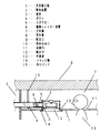
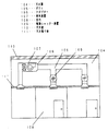
図1〜図3に示すように、下面に吸込口12を有し、最低1箇所以上の側部にダクト4と接続されるアダプター5を備えた吹出口9を設け、一端側に外方に突出したフランジ部14を有する箱体の内部に送風部として送風機を具備する機器である換気装置2が、図示していないが、天井壁8から吊り下げられた吊りボルトにナットで固定され、吊り下げられた状態で天井張り板1の埋め込み口10から箱体部分を天井裏7に入れて、吸込み口12面を天井張り板1面に合わせて配設されている。   As shown in FIG. 1 to FIG. 3, an air inlet 12 having an inlet 12 on the lower surface and having an adapter 5 connected to the duct 4 is provided on at least one side, and outwardly on one end side. Although not shown, the ventilation device 2, which is a device including a blower as a blower, is fixed to a suspension bolt suspended from the ceiling wall 8 with a nut and suspended. In the lowered state, the box portion is put into the ceiling back 7 from the embedding port 10 of the ceiling board 1, and the suction port 12 surface is arranged in accordance with the surface of the ceiling board 1.

換気装置2のアダプター5には、電動シャッター装置6のアダプター側筒体23のアダプター接続口16がアダプター5の外側に挿入され、図示していないがアルミ状のテープにより、テーピングされて固定されている。また、電動シャッター装置6のダクト側筒体24のダクト接続口18には、塩化ビニル製で断面丸型のダクト4がダクト接続口18の外側に挿入され、図示していないが、やはり、アルミ状のテープにより、テーピングされて固定されている。   In the adapter 5 of the ventilation device 2, the adapter connection port 16 of the adapter side cylinder 23 of the electric shutter device 6 is inserted outside the adapter 5, and is taped and fixed by an aluminum tape (not shown). Yes. In addition, a duct 4 made of vinyl chloride and having a round cross section is inserted into the duct connection port 18 of the duct side cylinder 24 of the electric shutter device 6, and is not shown. The tape is fixed by tape.

ダクト4は天井壁8に打ち込み固定した吊りバンド15で吊られた状態で固定され、壁を貫通して屋外3に連通させている。   The duct 4 is fixed in a state of being suspended by a suspension band 15 that is driven into and fixed to the ceiling wall 8, and communicates with the outdoor 3 through the wall.

また、換気装置2の取付箇所の近傍には点検口11が有り、この点検口11から作業者13が換気装置2と電動シャッター装置6の点検や修理を行うことができる。   An inspection port 11 is provided in the vicinity of the place where the ventilation device 2 is attached, and an operator 13 can inspect and repair the ventilation device 2 and the electric shutter device 6 from the inspection port 11.

ここで、電動シャッター装置について詳細説明する。   Here, the electric shutter device will be described in detail.

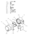
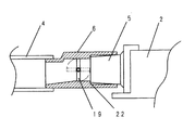
図2及び図3に示すように、アダプター5が内挿され接続されるアダプター側筒体の一方にはアダプター接続口があり、このアダプター接続口16の内周部にアダプター5の先端部を当接させるために、アダプアー接続口16の円中心方向に突出する段差22を設け、この段差の内周下部にはそのアダプター当接面からダクト接続口方向(排気方向)に勾配のついた溝26を設け、この溝26は電動シャッター装置が組み立てられた状態ではダクト接続口18の最端まで連続して設けられている。   As shown in FIGS. 2 and 3, one of the adapter side cylinders to which the adapter 5 is inserted and connected has an adapter connection port, and the tip of the adapter 5 is placed on the inner periphery of the adapter connection port 16. In order to make contact, a step 22 projecting toward the center of the circle of the adapter connection port 16 is provided, and a groove 26 having a gradient from the adapter abutment surface to the duct connection port direction (exhaust direction) is provided at the lower inner periphery of the step. The groove 26 is continuously provided to the end of the duct connection port 18 in a state where the electric shutter device is assembled.

また、アダプター側筒体23のもう一方側には外周にダクト側筒体24への差込み代を設け、この差込み代は外周径とは若干小径となり、外挿されるダクト側筒体の当たり部としての段差を設けることとなる。このアダプター側筒体23のもう一方側の円筒中央の水平面上にはシャッター軸を保持する2箇所U字の切り欠き部25を備え、U字切り欠き部25の内縁が山形状になっている。   Further, an insertion allowance to the duct side cylinder 24 is provided on the outer periphery on the other side of the adapter side cylinder 23. This insertion allowance is slightly smaller than the outer diameter, and serves as a contact portion for the duct side cylinder to be extrapolated. Will be provided. On the other side of the adapter-side cylinder 23 on the horizontal plane of the center of the cylinder, there are two U-shaped notches 25 for holding the shutter shaft, and the inner edge of the U-shaped notch 25 has a mountain shape. .

ダクト側筒体24の円筒の外側に一体成形された電動開閉器21を納める箱体17aを半割状態で形成する。電動開閉器21はアダプター側筒体23のU字切り欠きにシャッター19を挿入した後、アダプター側筒体23にダクト側筒体24を差込み組立てした後、その組み立てた筒体の中央部分の外側面で、該両筒体の各々に渡ってねじ止めするようになっており、従って、電動開閉器21を収める箱体は該両筒体の其々に半割状態で形成されている。   A box body 17a for accommodating the electric switch 21 integrally formed on the outside of the cylinder of the duct side cylinder 24 is formed in a half-split state. The electric switch 21 is constructed by inserting the shutter 19 into the U-shaped notch of the adapter-side cylinder 23, inserting the duct-side cylinder 24 into the adapter-side cylinder 23 and assembling it, and then removing it from the central portion of the assembled cylinder. On the side surface, it is designed to be screwed over each of the two cylinders. Therefore, the box for housing the electric switch 21 is formed in a half state in each of the two cylinders.

シャッター19は円形状であり、その円中心に該シャッターの開閉動作中心となる円柱形のシャッター軸が一体成形され、そのシャッター軸の一端側には楕円形状の板を備え、この楕円形状の板面上にシャッター軸の線上からずらして開閉器と連結させる突起部を備えている。   The shutter 19 has a circular shape, and a cylindrical shutter shaft that is the center of opening / closing operation of the shutter is integrally formed at the center of the circle, and an elliptical plate is provided on one end side of the shutter shaft. A protrusion is provided on the surface to be connected to the switch while being shifted from the line of the shutter axis.

ダクト側筒体24は、一方にダクト4が外挿される円筒形状のダクト接続口18を備え、もう一方側にはアダプター側筒体23とを挿着する差込み接続口を備え、この差込み接続口端部にアダプター側筒体23のU字の切り欠きに係合するU字形状の切り欠き部25を2箇所設け、また、該もう一方側の円筒形内部にはアダプター側筒体23と差込み合体させた際に当接させる段差22を備え、その段差22にアダプター側筒体23の円筒形内部に備える溝と連続するように排気側への勾配を設けた溝26を有している。   The duct side cylinder 24 is provided with a cylindrical duct connection port 18 into which the duct 4 is extrapolated on one side, and an insertion connection port for inserting and attaching the adapter side cylinder 23 on the other side. Two U-shaped cutouts 25 are provided at the end to engage with the U-shaped cutout of the adapter-side cylinder 23, and the adapter-side cylinder 23 is inserted into the other cylindrical part. A step 22 is provided to be brought into contact when combined, and the step 22 has a groove 26 provided with a gradient toward the exhaust side so as to be continuous with the groove provided in the cylindrical shape of the adapter-side cylinder 23.

また、ダクト側筒体24の円筒の外側には一体成形された電動開閉器21を治める箱体17bを半割状態で形成する。この半割状態の箱体の排気側方向すなわちダクト接続口方向の側端面に2箇所の排気方向に突起する突起部を設ける。   In addition, a box body 17b that governs the integrally formed electric switch 21 is formed in a halved state outside the cylinder of the duct side cylinder body 24. Two projecting portions projecting in the exhaust direction are provided on the side end face in the exhaust side direction, that is, in the duct connection port direction of the half box.

この突起部に蓋を引っ掛けて、箱体に蓋をすることになる。すなわち、ダクト側筒体24とアダプター側筒体23を差込み組み合わせることにより、前記の半割状態の箱体17a及び同箱体17bが合体して1つの完成された箱体になる。この箱体の奥面には2箇所の取り付け用のねじ座があり、このねじ座に前記シャッター19と連結させる電動開閉器21を納めねじ固定する。電動開閉器21をねじ止め固定した後、前記箱体17bに設けられたダクト接続方向に突出した2個の爪部に蓋を引掛け、この蓋で前記電動開閉器21を納めた箱体を覆い、前記箱体17aに設けられたネジボスに該蓋をねじ止め固定する。当然、蓋20にはネジを通すばか穴を備える。   A lid is hooked on this protrusion to cover the box. That is, by inserting and combining the duct side cylinder 24 and the adapter side cylinder 23, the half box 17a and the box 17b are combined to form one completed box. There are two mounting screw seats on the inner surface of the box, and an electric switch 21 to be connected to the shutter 19 is housed and fixed to the screw seats. After the electric switch 21 is screwed and fixed, a lid is hooked on the two claws provided in the box body 17b and projecting in the duct connecting direction, and the box body in which the electric switch 21 is housed with this lid. Cover and fix the lid to the screw boss provided on the box body 17a by screwing. Naturally, the lid 20 is provided with a fool hole through which a screw is passed.

以上の詳説のように、一方側はダクトが外挿されて接続し、他方側は、前記アダプター5が内挿され接続される電動シャッター装置が構成されている。   As described in detail above, an electric shutter device is configured in which a duct is extrapolated and connected on one side, and the adapter 5 is inserted and connected on the other side.

次に電動シャッター装置の取付について詳細説明する。   Next, the mounting of the electric shutter device will be described in detail.

天井張り板1に埋め込み口10を設け、埋め込み口10から作業者13が手を入れて、天井裏7内に吊りバンド等で吊り下げ固定された塩ビ製、亜鉛鉄板製、アルミ板等の円形ダクト4に電動シャッター装置6のダクト側筒体24のダクト接続口18をダクト4のに内側に挿入し、そのダクト4との挿入した接合部をアルミテープ等のテープでテーピング固定する。   The ceiling board 1 is provided with an embedding port 10, and an operator 13 puts a hand through the embedding port 10 and is suspended and fixed in a ceiling band 7 with a hanging band or the like, and is made of PVC, zinc iron plate, aluminum plate or the like. The duct connection port 18 of the duct side cylinder 24 of the electric shutter device 6 is inserted into the duct 4 on the inside of the duct 4, and the joined portion with the duct 4 is fixed by taping with tape such as aluminum tape.

ここで、装置の取り付け方向について補追説明する。   Here, a supplementary explanation will be given regarding the mounting direction of the apparatus.

本電動シャッター装置には2つの方向性を設けてある。まず、差込みの方向性についてはダクト側に差し込み出来るのはダクト接続口18しかなく、アダプター接続口16にはダクト4は接続できなくなっている。すなわち、筒サイズを各々に合うサイズにするとともに、アダプター接続口16のあるアダプター側筒体23の外周には差し込み代とダクト4を当接する段差を設けず、ダクト接続口18にダクト4を外挿する差込み代とダクト4を当接する段差を設けてある。   This electric shutter device has two directions. First, regarding the direction of insertion, only the duct connection port 18 can be inserted into the duct side, and the duct 4 cannot be connected to the adapter connection port 16. That is, the cylinder size is made suitable for each, and the outer periphery of the adapter side cylinder 23 with the adapter connection port 16 is not provided with a step for contacting the insertion allowance and the duct 4, and the duct 4 is connected to the duct connection port 18. A step for abutting the insertion allowance with the duct 4 is provided.

次に、水平方向については、装置内に設けてある溝26が必ず下側に位置するように装置の外縁に表示板にて表示するとともに、装置を取付した状態で電動開閉器21の箱体の下側になる側面が装置筒のほぼ最外周になるように寸法建てされており、装置を置いた状態で安定した状態が正方向であるよう外観上でも方向性が分かるように工夫されている。   Next, in the horizontal direction, the display 26 is displayed on the outer edge of the apparatus so that the groove 26 provided in the apparatus is surely located on the lower side, and the box of the electric switch 21 with the apparatus attached. It is dimensioned so that the side surface on the lower side is almost the outermost circumference of the device cylinder, and it is devised so that the directionality can be understood even on the appearance so that the stable state is the positive direction when the device is placed Yes.

以上の取付の方向性を意識しながら取付を行う。   Install with the above direction of attachment in mind.

ここで、説明を装置取付に戻す。   Here, the description returns to the device attachment.

ダクト4をダクト接続口18に固定した後、アダプター側の取り付け固定を行う。   After fixing the duct 4 to the duct connection port 18, the adapter side is attached and fixed.

電動シャッター装置6のアダプター側筒体23に設けられたアダプター接続口16に換気装置側のアダプター5を内側に差込み挿入し、アダプター接続口16の差込み代終端に設けられた段差にアダプターを当接安定させ、その接合部をアルミテープ等でテーピング固定し、天井張り板1にアダプター5のフランジ部分を当接させ固定する。または、前記アダプター5と電動シャッター装置6とを作業者13の手元で接続固定し、埋め込み口10から天井裏7内にあるダクト4に電動シャッター装置6を接続固定し、天井張り板1にアダプター5を当接させ固定する。天井張り板1の上側にある天井裏7の空間に換気装置2を埋め込み口10より入れ込み、前記アダプター5に装着させ、フランジ部14の水平面を天井張り板1の室内面と当接させ、最終段階で電動シャッターと換気装置の電気接続を行い、配線を完了する。作業者13は一箇所の点検口11より覗きながら、電気配線及び各装置の設置作業を一度にすることができるものである。   The adapter 5 on the ventilation device side is inserted and inserted into the adapter connection port 16 provided on the adapter side cylinder 23 of the electric shutter device 6, and the adapter is brought into contact with the step provided at the insertion end of the adapter connection port 16. Stabilize and tap and fix the joint with aluminum tape or the like, and fix the flange portion of the adapter 5 to the ceiling plate 1. Alternatively, the adapter 5 and the electric shutter device 6 are connected and fixed by the operator 13, the electric shutter device 6 is connected and fixed from the embedding port 10 to the duct 4 in the ceiling back 7, and the adapter is attached to the ceiling board 1. 5 is contacted and fixed. The ventilation device 2 is inserted into the space of the ceiling back 7 on the upper side of the ceiling board 1 through the embedding port 10 and attached to the adapter 5, and the horizontal surface of the flange portion 14 is brought into contact with the indoor surface of the ceiling board 1. At the stage, electrical connection between the electric shutter and the ventilator is completed, and wiring is completed. The operator 13 can perform the installation work of the electric wiring and each device at one time while looking through the inspection port 11 at one place.

ここでアダプター5について補追説明する。   Here, supplementary explanation of the adapter 5 will be given.

本実施の形態のアダプター5は換気装置2の箱体とは別物となっている。すなわち、換気装置2の箱体とは別に、図示していないが、電動シャッター装置6のアダプター接続口16に接続するアダプター部分と天井張り板1にねじ止めするフランジ部分と換気装置2と係合して合体する部分を備えたものである。したがって、このアダプターを前もって天井張り板1に取り付けてその後、換気装置2の本体である箱体をアダプターに係合合体させて天井張り板1に取り付けるのである。   The adapter 5 of the present embodiment is different from the box of the ventilation device 2. That is, although not shown separately from the box of the ventilation device 2, the adapter portion connected to the adapter connection port 16 of the electric shutter device 6, the flange portion screwed to the ceiling board 1, and the ventilation device 2 are engaged. And a portion to be united. Therefore, the adapter is attached to the ceiling board 1 in advance, and then the box body which is the main body of the ventilation device 2 is engaged with the adapter and attached to the ceiling board 1.

ここで動作を説明する。   Here, the operation will be described.

換気装置2を運転させたときは、電動シャッター装置6のシャッター19が開放し、室内の空気を吸込み、側部のアダプター5と接続された電動シャッター装置6を通り、接続したダクト4より屋外3へ排出する。また、換気装置2が停止したときは電動シャッター装置6のシャッター19が閉鎖し、屋外3に連通したダクト4より侵入する外風を室内に入るのを防止する。   When the ventilation device 2 is operated, the shutter 19 of the electric shutter device 6 opens, sucks indoor air, passes through the electric shutter device 6 connected to the side adapter 5, and is connected to the outdoor 3 from the connected duct 4. To discharge. Further, when the ventilation device 2 is stopped, the shutter 19 of the electric shutter device 6 is closed to prevent the outside wind entering from the duct 4 communicating with the outdoor 3 from entering the room.

なお、本発明の電動シャッター装置を取り付ける装置は、中間ダクト、天埋換気扇、気調システム等の空調機または換気装置であっても、同様の効果を奏するものである。   In addition, even if the apparatus to which the electric shutter device of the present invention is attached is an air conditioner or a ventilator such as an intermediate duct, a natural ventilation fan, or an air conditioning system, the same effect can be obtained.

また、内部に送風機を有さない、いわゆる、単に換気または給排気口といわれるものであってもアダプター部分を有していれば、同じように接続ができ、同様の作用効果を奏するものである。   Moreover, even if it has what is called a ventilation or an air supply / exhaust port which does not have an air blower inside, if it has an adapter part, it can connect in the same way and has the same effect. .

繰り返しの説明になるが、天井裏7の空間にダクト4を配管し電動シャッター装置6を装着した換気装置2を設置するときは、図1に示すように行う。つまり、天井裏7内に屋外3に連通するダクト4を天井壁8に吊りバンド15で固定し、作業者13が天井張り板1に設けてある埋め込み口10より、電動シャッター装置6とアダプター5をダクト4に装着し、換気装置2を埋め込み設置する。電動シャッター装置6をアダプター5に直接装着して設置するため、同じ作業箇所で換気装置2設置のときに同時に行うことができる。また、メンテナンスを行うときも電動シャッター装置6と換気装置2が同じ場所に設置しているため、換気装置2と電動シャッター装置6を同時に行うことができる。しかし、従来の電動シャッター装置106であれば、図5に示すように換気装置107と電動シャッター装置109の設置場所が離れ、ダクト105中間に装着されているため、換気装置107と電動シャッター装置109の設置作業及び設置後のメンテナンスが、設置場所が離れているため、作業工数が多くかかってしまう。   To repeat, when installing the ventilation device 2 in which the duct 4 is installed in the space of the ceiling 7 and the electric shutter device 6 is mounted, it is performed as shown in FIG. That is, the duct 4 communicating with the outdoor 3 in the ceiling 7 is fixed to the ceiling wall 8 with the suspension band 15, and the electric shutter device 6 and the adapter 5 are inserted from the embedding port 10 provided by the operator 13 in the ceiling board 1. Is installed in the duct 4 and the ventilation device 2 is embedded. Since the electric shutter device 6 is directly attached to the adapter 5 and installed, it can be performed at the same time when the ventilation device 2 is installed at the same work location. Moreover, since the electric shutter device 6 and the ventilation device 2 are installed at the same place when performing maintenance, the ventilation device 2 and the electric shutter device 6 can be performed at the same time. However, in the case of the conventional electric shutter device 106, the ventilation device 107 and the electric shutter device 109 are installed in the middle of the duct 105 as shown in FIG. The installation work and maintenance after installation take a lot of work man-hours because the installation places are remote.

このように本発明の実施の形態1の電動シャッター装置によれば、ダクト接続口と換気装置に設けられたアダプターに直接装着させることができることにより、電動シャッター装置と換気装置が近接した場所で設置作業ができることにより、設置作業とメンテナンス作業の工数を減らすことができるものである。   Thus, according to the electric shutter device of the first embodiment of the present invention, the electric shutter device and the ventilation device can be installed directly in the vicinity of the duct connection port and the adapter provided in the ventilation device. By being able to work, the man-hours for installation work and maintenance work can be reduced.

ダクト間に接続するシャッター装置において、一方の接続を内挿接続、もう一方の接続を外挿接続とし、前記内挿接続側を換気装置に直接接続する構成とすることにより、空気の流れをスムーズに出来るとともに、結露水もスムーズに流すことができ、且つ、直接接続でシャッター装置と換気装置が近接するので、この両方への作業が同時、同位置作業となり、作業効率が向上することに成り、このような直接接続構成のシャッター装置は換気装置に限らず、単なる給排気口装置や換気ダクト等の被接続物への適用も可能なものである。   In the shutter device connected between the ducts, one connection is an interpolated connection, the other connection is an extrapolated connection, and the interpolated connection side is directly connected to the ventilation device, thereby smoothing the air flow. Condensed water can flow smoothly, and the shutter device and the ventilation device are close to each other by direct connection. The shutter device having such a direct connection configuration is not limited to a ventilation device, but can be applied to a connected object such as a simple air supply / exhaust device or a ventilation duct.

本発明の実施の形態1における電動シャッター装置と換気装置の取付状態説明図Explanatory drawing of the attachment state of the electric shutter device and the ventilation device in Embodiment 1 of the present invention 同電動シャッター装置の分解斜視図Exploded perspective view of the electric shutter device 同電動シャッター装置の接続部を示す断面図Sectional drawing which shows the connection part of the electric shutter device 従来の電動シャッター装置の断面図Sectional view of a conventional electric shutter device 同電動シャッター装置と換気装置の取付状態説明図Installation state explanatory diagram of the electric shutter device and ventilation device

符号の説明Explanation of symbols

1 天井張り板
2 換気装置
3 屋外
4 ダクト
5 アダプター
6 電動シャッター装置
7 天井裏
8 天井壁
9 吹出口
10 埋め込み口
11 点検口
12 吸込口
13 作業者
14 フランジ部
15 吊りバンド
16 アダプター接続口
17a 箱体
17b 箱体
18 ダクト接続口
19 シャッター
20 蓋
21 電動開閉器
22 段差
23 アダプター側筒体
24 ダクト側筒体
25 U字の切り欠き部
26 溝
DESCRIPTION OF SYMBOLS 1 Ceiling board 2 Ventilation device 3 Outdoor 4 Duct 5 Adapter 6 Electric shutter device 7 Ceiling back 8 Ceiling wall 9 Air outlet 10 Implantation port 11 Inspection port 12 Suction port 13 Worker 14 Flange part 15 Hanging band 16 Adapter connection port 17a Box Body 17b Box 18 Duct connection port 19 Shutter 20 Lid 21 Electric switch 22 Step 23 Adapter side cylinder 24 Duct side cylinder 25 U-shaped notch 26 Groove

Claims (17)

アダプター側筒体とダクト側筒体とシャッターから成り、アダプター側筒体またはダクト側筒体にシャッターを回動可能に保持する保持部を設け、この保持部にシャッターを保持した後、前記アダプター側筒体とダクト側筒体を係合させ合体組立てすることを特徴とするシャッター装置。 The adapter side cylinder, the duct side cylinder, and the shutter are provided, and the adapter side cylinder or the duct side cylinder is provided with a holding portion for rotatably holding the shutter, and after holding the shutter in the holding portion, the adapter side A shutter device characterized in that a cylindrical body and a duct side cylindrical body are engaged and assembled. アダプター側筒体とダクト側筒体とシャッターから成り、このシャッターにはこれを回動させるためのシャッター軸を設け、前記アダプター側筒体またはダクト側筒体には前記シャッター軸を回動可能に軸支する切り欠き部を設けるとともに、相互に差込み嵌合可能な嵌合部を設け、前記シャッター軸を前記切り欠き部に入れて軸支保持した後、前記アダプター側筒体とダクト側筒体を相互に差込み嵌合させて合体組立てすることを特徴とするシャッター装置。 It consists of an adapter-side cylinder, a duct-side cylinder, and a shutter, and this shutter is provided with a shutter shaft for rotating the shutter. The adapter-side cylinder or the duct-side cylinder can rotate the shutter shaft. The adapter side cylinder and the duct side cylinder are provided with a notch part to be pivotally supported and a fitting part that can be inserted and fitted to each other, and after the shutter shaft is inserted and held in the notch part. A shutter device characterized by being assembled and assembled by inserting and fitting together. アダプター側筒体とダクト側筒体とシャッターから成り、アダプター側筒体またはダクト側筒体にシャッターを回動可能に保持する保持部を設け、この保持部にシャッターを保持した後、前記アダプター側筒体とダクト側筒体を係合させ合体組立てするシャッター装置において、アダプター側筒体とダクト側筒体の材質を樹脂とし相互の合体組立ての際は差込み方式、分解する際は引き抜き方式としたシャッター装置。 The adapter side cylinder, the duct side cylinder, and the shutter are provided, and the adapter side cylinder or the duct side cylinder is provided with a holding portion for rotatably holding the shutter, and after holding the shutter in the holding portion, the adapter side In the shutter device that engages and assembles the cylinder body and the duct side cylinder body, the adapter side cylinder body and the duct side cylinder body are made of resin, and the insertion system is used for mutual assembly and the pulling system is used for disassembly. Shutter device. アダプター側筒体とダクト側筒体とシャッターから成り、これらアダプター側筒体とダクト側筒体の間にシャッターを回動可能に保持する構成のシャッター装置であって、前記アダプター側筒体のアダプター接続口へのアダプター接続はアダプターをアダプター接続口の内側へ差し込む接続構成とし、ダクト側筒体のダクト接続部へのダクト接続はダクトをダクト接続口の外側へ差し込む接続構成としたことを特徴とするシャッター装置。 A shutter device comprising an adapter-side cylinder, a duct-side cylinder, and a shutter, wherein the shutter is rotatably held between the adapter-side cylinder and the duct-side cylinder, and the adapter of the adapter-side cylinder The adapter connection to the connection port is a connection configuration in which the adapter is inserted inside the adapter connection port, and the duct connection to the duct connection portion of the duct side cylinder is a connection configuration in which the duct is inserted outside the duct connection port. Shutter device to do. 風上となる筒体と風下となる筒体とシャッターから成り、これら風上となる筒体と風下となる筒体の間にシャッターを回動可能に保持する構成のシャッター装置であって、前記風上となる筒体の接続口への接続は被接続物を該接続口の内側へ差し込む接続構成とし、風下となる筒体の接続部への接続は被接続物を該接続口の外側へ差し込む接続構成としたことを特徴とするシャッター装置。 A shutter device comprising a cylindrical body serving as the windward, a cylindrical body serving as the leeward, and a shutter, wherein the shutter is rotatably held between the cylindrical body serving as the windward and the cylindrical body serving as the leeward, The connection to the connection port of the cylinder that becomes the windward is a connection configuration in which the object to be connected is inserted into the connection port, and the connection to the connection part of the cylinder that becomes the leeward is the connection object to the outside of the connection port. A shutter device characterized by having a connection configuration to be plugged in. アダプター側筒体とダクト側筒体とシャッターから成り、これらアダプター側筒体とダクト側筒体の間にシャッターを回動可能に保持する構成のシャッター装置であって、前記アダプター側筒体のアダプター接続口へのアダプター接続はアダプターをアダプター接続口の内側へ差し込む接続構成とし、ダクト側筒体のダクト接続部へのダクト接続はダクトをダクト接続口の外側へ差し込む接続構成とするとともに、前記アダプターの差込み終端部から前記ダクト接続部端部に至る間には結露水等をダクト側へ流すための溝を設けたことを特徴とするシャッター装置。 A shutter device comprising an adapter-side cylinder, a duct-side cylinder, and a shutter, wherein the shutter is rotatably held between the adapter-side cylinder and the duct-side cylinder, and the adapter of the adapter-side cylinder The adapter connection to the connection port is a connection configuration in which the adapter is inserted inside the adapter connection port, and the duct connection to the duct connection portion of the duct side cylinder is a connection configuration in which the duct is inserted to the outside of the duct connection port. A shutter device is provided with a groove for allowing condensed water or the like to flow to the duct side from the insertion end of the duct to the end of the duct connection. アダプターにダクトを接続して換気をする換気装置の該アダプターに直接装着することを特徴とする請求項1〜6のいずれかに記載のシャッター装置。 The shutter device according to claim 1, wherein the shutter device is directly attached to the adapter of a ventilator that ventilates by connecting a duct to the adapter. 請求項1〜7のいずれかに記載のシャッター装置に、該シャッターを電気的に開閉するための開閉器を設けた電動シャッター装置。 An electric shutter device provided with a switch for electrically opening and closing the shutter in the shutter device according to claim 1. 請求項1〜7のいずれかに記載のシャッター装置または請求項8記載の電動シャッター装置を、アダプターにダクトを接続して換気をする換気装置の該アダプターに直接装着するシャッター装置の取付方法。 A shutter device mounting method for directly mounting the shutter device according to any one of claims 1 to 7 or the electric shutter device according to claim 8 to the adapter of a ventilation device that ventilates by connecting a duct to the adapter. 屋外に連通するダクトに接続される円筒形のダクト接続口を備えたダクト側筒体と、アダプターに装着するための円筒形のアダプター接続口を備えたアダプター側筒体と、電気的に回動するシャッターを備えた装置であって、天面または側面にダクトと接続されるアダプターを設けた箱体を備えた換気装置の前記アダプターに、前記アダプター接続口を直接装着することを特徴とする電動シャッター装置。 A duct side cylinder with a cylindrical duct connection port connected to a duct communicating with the outdoors, and an adapter side cylinder with a cylindrical adapter connection port for mounting on an adapter, and electrical rotation An electric device characterized in that the adapter connection port is directly attached to the adapter of a ventilator provided with a box body provided with an adapter connected to a duct on the top surface or a side surface. Shutter device. 一方側は換気装置に設けられたアダプターが内挿されて接続され、他方側はダクトが外挿されて接続され通風路を形成することを特徴とする請求項10に記載の電動シャッター装置。 11. The electric shutter device according to claim 10, wherein an adapter provided in the ventilation device is inserted and connected on one side, and a duct is extrapolated and connected on the other side to form an air passage. 換気装置に設けられたアダプターが内挿され接続される側の内周部に、前記アダプター先端部と当接させる段差を備える請求項10または11に記載の電動シャッター装置。 The electric shutter device according to claim 10 or 11, further comprising a step that abuts the tip of the adapter on an inner peripheral portion on a side where an adapter provided in the ventilation device is inserted and connected. シャッターは、屋外と換気装置を連通させるダクトから侵入する外風を強制的に遮断させるものであり、該シャッターの形状は円形状で、その材質を樹脂としたことを特徴とする請求項10〜12のいずれかに記載の電動シャッター装置。 The shutter is configured to forcibly block outside wind entering from a duct that communicates the outdoors with a ventilator, and the shape of the shutter is circular and the material thereof is resin. The electric shutter device according to any one of 12. シャッターの開閉軸が、ダクト接続口を正面視したときにシャッターを略均等に2分割することを特徴とする請求項10〜13のいずれかに記載の電動シャッター装置。 The electric shutter device according to any one of claims 10 to 13, wherein the opening / closing shaft of the shutter divides the shutter into two substantially evenly when the duct connection port is viewed from the front. 差込み合体されているダクト側筒体とアダプター側筒体を、相互に引き抜き分割可能な構成とした構成とした請求項10〜14のいずれかに記載の電動シャッター装置。 The electric shutter device according to any one of claims 10 to 14, wherein the duct-side cylinder and the adapter-side cylinder that are merged together are configured to be capable of being pulled out and divided from each other. アダプターに接続する接続口を備えるアダプター側筒体にシャッター軸を保持する切り欠き部を設け、前記シャッター軸が回動自在に接触する前記切り欠き部の内縁肉厚を盛り上げて山形状にした請求項10〜15のいずれかに記載の電動シャッター装置。 An adapter-side cylinder having a connection port for connecting to an adapter is provided with a notch for holding the shutter shaft, and the inner wall thickness of the notch at which the shutter shaft is rotatably contacted is raised to form a mountain shape. Item 15. The electric shutter device according to any one of Items 10 to 15. 換気装置は、その内部に送風機を有さず、ダクトと接続されるアダプターを備えたものとし、該換気装置の前記アダプターに接続することを特徴とする請求項10〜16のいずれかに記載の電動シャッター装置。 The ventilator does not have a blower in its interior and is provided with an adapter connected to a duct, and is connected to the adapter of the ventilator. Electric shutter device.
JP2004113817A 2004-04-08 2004-04-08 Electric shutter device Expired - Fee Related JP4396364B2 (en)

Priority Applications (1)

Application Number Priority Date Filing Date Title
JP2004113817A JP4396364B2 (en) 2004-04-08 2004-04-08 Electric shutter device

Applications Claiming Priority (1)

Application Number Priority Date Filing Date Title
JP2004113817A JP4396364B2 (en) 2004-04-08 2004-04-08 Electric shutter device

Publications (2)

Publication Number Publication Date
JP2005299970A true JP2005299970A (en) 2005-10-27
JP4396364B2 JP4396364B2 (en) 2010-01-13

Family

ID=35331719

Family Applications (1)

Application Number Title Priority Date Filing Date
JP2004113817A Expired - Fee Related JP4396364B2 (en) 2004-04-08 2004-04-08 Electric shutter device

Country Status (1)

Country Link
JP (1) JP4396364B2 (en)

Cited By (1)

* Cited by examiner, † Cited by third party
Publication number Priority date Publication date Assignee Title
JP2013148299A (en) * 2012-01-20 2013-08-01 Mitsubishi Electric Corp Ventilation device

Cited By (1)

* Cited by examiner, † Cited by third party
Publication number Priority date Publication date Assignee Title
JP2013148299A (en) * 2012-01-20 2013-08-01 Mitsubishi Electric Corp Ventilation device

Also Published As

Publication number Publication date
JP4396364B2 (en) 2010-01-13

Similar Documents

Publication Publication Date Title
CN104482596B (en) Wall-mounted indoor air-conditioner easy to mount and demount
JP5436981B2 (en) Wall-mounted air conditioner
CA2483946A1 (en) Quick connect mounting system for a ceiling fan
KR20090102932A (en) Diffuser
CN105805918B (en) An air conditioner indoor unit
JP2009052767A (en) Facility equipment
EP0791789A2 (en) Discrete type air conditioner
KR101490223B1 (en) Ventilator
JP2005299970A (en) Shutter device
CN209131025U (en) Air conditioner wall-mounted machine and air conditioner
KR20100052385A (en) Indoor unit for air conditioning apparatus and assembling method thereof
KR200450750Y1 (en) Duct frame fixing structure of air conditioner diffuser
CN222067118U (en) Ventilation fans for ceiling ducts
CN208652745U (en) Grid for air conditioner, shell for air conditioner and air conditioner outdoor unit
JP7257991B2 (en) ventilation fan for duct
WO2021219109A1 (en) Air conditioner indoor unit allowing removal for washing
JP2006084080A (en) Ventilation device and ventilation system
JPH0347154Y2 (en)
JP2997171B2 (en) Fan for air supply type pipe
CN220452238U (en) Ventilator with compact structure
CN214249831U (en) Air conditioner auxiliary air duct assembly
CN112413875A (en) An air conditioner panel support structure and an air conditioner
JPH0330731Y2 (en)
CN111279083A (en) Duct fan
KR100874235B1 (en) Case of air conditioner

Legal Events

Date Code Title Description
A621 Written request for application examination

Free format text: JAPANESE INTERMEDIATE CODE: A621

Effective date: 20060914

RD01 Notification of change of attorney

Free format text: JAPANESE INTERMEDIATE CODE: A7421

Effective date: 20061012

A977 Report on retrieval

Free format text: JAPANESE INTERMEDIATE CODE: A971007

Effective date: 20090623

A131 Notification of reasons for refusal

Free format text: JAPANESE INTERMEDIATE CODE: A131

Effective date: 20090630

A521 Request for written amendment filed

Free format text: JAPANESE INTERMEDIATE CODE: A523

Effective date: 20090827

TRDD Decision of grant or rejection written
A01 Written decision to grant a patent or to grant a registration (utility model)

Free format text: JAPANESE INTERMEDIATE CODE: A01

Effective date: 20090929

A01 Written decision to grant a patent or to grant a registration (utility model)

Free format text: JAPANESE INTERMEDIATE CODE: A01

A61 First payment of annual fees (during grant procedure)

Free format text: JAPANESE INTERMEDIATE CODE: A61

Effective date: 20091012

FPAY Renewal fee payment (event date is renewal date of database)

Free format text: PAYMENT UNTIL: 20121030

Year of fee payment: 3

R151 Written notification of patent or utility model registration

Ref document number: 4396364

Country of ref document: JP

Free format text: JAPANESE INTERMEDIATE CODE: R151

FPAY Renewal fee payment (event date is renewal date of database)

Free format text: PAYMENT UNTIL: 20131030

Year of fee payment: 4

LAPS Cancellation because of no payment of annual fees